NOTICE: This publication is available digitally on the AFDPO WWW site at: http://afpubs.hq.af.mil. I f you lack access, contact your Publishing Distribution Office (PDO). COMPLIANCE WITH THIS PUBLICATION IS MANDATORY BY ORDER OF THE SECRETARY OF THE AIR FORCE AIR FORCE INSTRUCTION 11-2F-16, VOLUME 3 1 JULY 1999 Flying Operations F-16--OPERATIONS PROCEDURES OPR: HQ ACC/XOFT (Maj Douglas E. Young) Certified by: HQ USAF/XOO (Maj Gen Michael S. Kudlacz) Supersedes MCI 11-F16V3, 21 April 1995; EMC 96-1, 041750Z Mar 96; IC 98-1, 211355Z Jan 98; IC 98-2, 162055Z Jul 98 Pages: 94 Distribution: F This volume implements AFPD 11-2, Aircraft Rules and Procedures; AFPD 11-4, Aviation Service; and AFI 11-202V3, General Flight Rules. It applies to all F-16 units. MAJCOM/DRU/FOA-level supple- ments to this volume are to be approved prior to publication IAW AFPD 11-2. Copies of MAJCOM/ DRU/FOA-level supplements, after approved and published, will be provided by the issuing MAJCOM/ DRU/FOA to HQ AFFSA/XOF, HQ ACC/XOFT, and the user MAJCOM and ANG offices of primary responsibility. Field units below MAJCOM/DRU/FOA level will forward copies of their supplements to this publication to their parent MAJCOM/DRU/FOA office of primary responsibility for post publication review. NOTE: The terms direct reporting unit (DRU) and field operating agency (FOA) as used in this paragraph refer only to those DRUs/FOAs that report directly to HQ USAF. Keep supplements current by complying with AFI 33-360V1, Publications Management Program. See paragraph 1.4. of this volume for guidance on submitting comments and suggesting improvements to this publication. This publication is affected by the Paperwork Reduction Act of 1974 as amended in 1996. Maintain and dispose of records created as a result of processes prescribed in this publication in accordance with AFMAN 37-139, Records Disposition Schedule. This volume, with its complementary unit-specific Local Procedures Supplement, prescribes standard operational and weapons employment procedures to be used by all pilots operating USAF F-16 aircraft. USAFAWC aircraft may deviate from the contents of this volume as outlined in individually approved test plans required for Test and Evaluation purposes. File a copy of all approved waivers with this volume. This volume contains references to the following field (subordinate level) publications which, until con- verted to departmental-level publications, may be obtained from the respective MAJCOM publishing office: Publications: MCR 55-125 (ACC)
Transcript
NOTICE: This publication is available digitally on the AFDPO WWW site at: http://afpubs.hq.af.mil. Ifyou lack access, contact your Publishing Distribution Office (PDO).
COMPLIANCE WITH THIS PUBLICATION IS MANDATORY
BY ORDER OF THE SECRETARY OF THE AIR FORCE
AIR FORCE INSTRUCTION 11-2F-16, VOLUME 3
1 JULY 1999
Flying Operations
F-16--OPERATIONS PROCEDURES
OPR: HQ ACC/XOFT (Maj Douglas E. Young)
Certified by: HQ USAF/XOO (Maj Gen Michael S. Kudlacz)
Supersedes MCI 11-F16V3, 21 April 1995; EMC 96-1, 041750Z Mar 96; IC 98-1, 211355Z Jan 98; IC 98-2, 162055Z Jul 98
Pages: 94Distribution: F
This volume implements AFPD 11-2, Aircraft Rules and Procedures; AFPD 11-4, Aviation Service; andAFI 11-202V3, General Flight Rules. It applies to all F-16 units. MAJCOM/DRU/FOA-level supple-ments to this volume are to be approved prior to publication IAW AFPD 11-2. Copies of MAJCOM/DRU/FOA-level supplements, after approved and published, will be provided by the issuing MAJCOM/DRU/FOA to HQ AFFSA/XOF, HQ ACC/XOFT, and the user MAJCOM and ANG offices of primaryresponsibility. Field units below MAJCOM/DRU/FOA level will forward copies of their supplements tothis publication to their parent MAJCOM/DRU/FOA office of primary responsibility for post publicationreview. NOTE: The terms direct reporting unit (DRU) and field operating agency (FOA) as used in thisparagraph refer only to those DRUs/FOAs that report directly to HQ USAF. Keep supplements current bycomplying with AFI 33-360V1, Publications Management Program. See paragraph 1.4. of this volumefor guidance on submitting comments and suggesting improvements to this publication. This publicationis affected by the Paperwork Reduction Act of 1974 as amended in 1996. Maintain and dispose of recordscreated as a result of processes prescribed in this publication in accordance with AFMAN 37-139,Records Disposition Schedule.
This volume, with its complementary unit-specific Local Procedures Supplement, prescribes standardoperational and weapons employment procedures to be used by all pilots operating USAF F-16 aircraft.USAFAWC aircraft may deviate from the contents of this volume as outlined in individually approved testplans required for Test and Evaluation purposes. File a copy of all approved waivers with this volume.
This volume contains references to the following field (subordinate level) publications which, until con-verted to departmental-level publications, may be obtained from the respective MAJCOM publishingoffice:
Publications: MCR 55-125 (ACC)
2 AFI 11-2F-16V3 1 JULY 1999
Note: This publication incorporates all using MAJCOMs' Sup 1 using the paragraph supplementationmethod. Supplemental material is prefaced with (MAJCOM).
Chapter 1—INTRODUCTION 6
1.1. General ....................................................................................................................... 6
1.2. Tech Data ................................................................................................................... 6
8.1. General ....................................................................................................................... 49
8.2. Local Operating Procedures ....................................................................................... 49
AFI 11-2F-16V3 1 JULY 1999 5
Attachment 1—GLOSSARY OF REFERENCES AND SUPPORTING INFORMATION 51
Attachment 2—FLIGHT BRIEFING GUIDES 56
Attachment 3—CRITICAL ACTION PROCEDURES (CAPs) 92
6 AFI 11-2F-16V3 1 JULY 1999
Chapter 1
INTRODUCTION
1.1. General:
1.1.1. Scope. This volume outlines the procedures applicable to the safe operation of the F-16. Withthe complementary references cited, this volume prescribes standard operational procedures to beused by all USAF F-16 pilots.
1.1.2. Pilot's Responsibility. This volume, in conjunction with other governing directives, pre-scribes operations procedures for F-16 under most circumstances, but is not to be used as a substitutefor sound judgment or common sense. Operations or procedures not specifically addressed may beaccomplished if they enhance safe and effective mission accomplishment
1.1.3. Deviations. Deviations from these procedures require specific approval of the MAJCOM/DOunless an urgent requirement or an aircraft emergency dictate otherwise, in which case the pilot incommand will take the appropriate action to safely recover the aircraft.
1.1.4. References. The primary references for F-16 operations are T.O.s 1F-16-1, 1F-16-1-1,1F-16-1-2, 1-1C-1, 1-1C-1-30, AFTTP 3-1V5, Tactical Employment--F-16; AFTTP 3-3V5, CombatAircraft Fundamentals--F-16; AFI 11-214, Aircrew, Weapons Director, and Terminal Attack Control-ler Procedures for Air Operations; and this volume. Training units may develop phase manuals fromthe procedures contained in these documents. Phase manuals may be used to augment initial and mis-sion qualification training at operational units. Phase manuals may expand these basic procedures; inno case will they be less restrictive.
1.2. Tech Data. Personnel will not operate new equipment or modified aircraft without properly vali-dated and verified tech data in accordance with 00-5 series T.O.s. If properly procured and verified techdata does not accompany new equipment or aircraft modifications delivered to the field, personnel willnot accept these aircraft or modified equipment. Red line (Mark-up) copies are not acceptable. Excep-tions to this policy are extremely limited and must be authorized by MAJCOM through DO and LG func-tional managers. PACAF waiver authority is FW/CC.
1.3. Waivers. Waiver requests will be forwarded through appropriate channels to the applicable MAJ-COM/DO for approval. Waivers, if approved, will be issued for a maximum of one year from the effec-tive date. Information copies of approved waivers will be provided to the lead and user MAJCOM OPRsfor this volume.
1.4. Volume Changes. Send recommended changes to this publication on AF Form 847, Recommenda-tion for Change of Publication, through channels, to HQ ACC/XOFT, 205 Dodd Blvd, Suite 101, Lan-gley AFB VA 23665-2789.
1.5. Distribution. Each F-16 pilot is authorized a copy of this volume.
AFI 11-2F-16V3 1 JULY 1999 7
Chapter 2
MISSION PLANNING
2.1. Responsibilities. The pilot in command of each aircraft and the designated flight lead are ultimatelyresponsible for mission planning. The operations and intelligence functions will provide supplementalplanning material and information as required to effectively accomplish the assigned mission.
2.2. General Procedures:
2.2.1. Accomplish sufficient flight planning to ensure safe mission accomplishment to include fuelrequirements, map preparation, and takeoff/landing data.
2.2.2. Plan and fly with sufficient ground attack planning information to conduct the attack safely.This may include stick diagrams, attack parameters, and/or unit developed attack cards.
2.2.3. (PACAF) Planned flights over water outside the local training area (e.g., deployments, crosscountries, and PDM inputs) will be accomplished two-ship as a minimum. Single-ship over waterflights require wing commander approval.
2.2.4. (PACAF) F-16s will carry an Acceleration Monitoring Device (AMD) to the maximum extentpossible. AMD carriage is not always possible or desired, but AMDs should be carried when sched-uled and mission requirements permit. OG/CC is approval authority for flights without AMD pods.
2.3. Takeoff and Landing Data:
2.3.1. Compute a 2,000 foot acceleration check speed anytime the computed takeoff roll exceeds2,500 feet. When the computed takeoff roll is 2,500 feet or less, use the actual takeoff distance versusthe computed takeoff distance to evaluate aircraft performance.
2.3.2. Compute a refusal speed for all takeoffs.
2.3.3. Minimum Takeoff and Landing Data (TOLD) requirements on Mission Data Cards are: accel-eration check speed, refusal/maximum abort speed (dry/wet), rotation speed, takeoff speed and dis-tance, and normal and heavyweight (landing immediately after takeoff) landing speeds and distances(dry/wet).
2.4. Map/Chart Preparation:
2.4.1. Local Area Maps. A local area map is not required if pilot aids include jettison areas, divertinformation, controlled bailout areas and provide sufficient detail of the local area to remain withinassigned training areas.
2.4.2. Charts. FLIP enroute charts may be used instead of maps on navigational flights within areaswhich are adequately covered by these charts.
2.4.3. Low Altitude Maps:
2.4.3.1. On low altitude flights, each pilot in the flight will carry a current map of the low altituderoute/operating area. The map will be of such scale and quality that terrain features, hazards, andchart annotations are of sufficient detail to allow individual navigation and safe mission accom-plishment.
8 AFI 11-2F-16V3 1 JULY 1999
2.4.3.2. Prepare maps for low level IAW MCR 55-125, Preparation of Mission Planning Materi-als (Tactical Aircraft), and as directed locally. Maps will be updated from the Chart Update Man-ual (CHUM) and all man-made obstacles which may be a factor to the flight will be highlighted(circled / marked with highlighter, etc) on the maps. Additionally, time and/or distance tick-markswill be annotated on low-level maps to ensure positive positional awareness of obstacles along theplanned route of flight plus or minus 5 NM.
2.4.3.3. Annotate all maps with a route abort altitude (RAA). Compute the RAA for the entireroute/area at a minimum of 1,000 feet separation from the highest obstacle/terrain feature(rounded to the next highest 100 feet) within the lateral limits of the route or training area, but inno case less than 5 NM either side of planned route.
2.4.4. Night. Night or simulated night radar low level flight map preparation:
2.4.4.1. The minimum pilot chart requirement is a flight log or stick chart. The minimum annota-tions for this log/chart are headings, RAAs, minimum safe altitudes (MSAs), recovery MSA(RMSA - if applicable) and maximum/minimum route structure altitudes.
2.4.4.2. Compute the MSA for each leg of the intended route of flight. The MSA is defined as analtitude which provides 1,000 feet of clearance above the highest obstacle/terrain feature (roundedto the next highest 100 feet) within 5 NM of the planned course, route boundaries, or operatingarea.
2.4.4.3. To ensure maps accurately reflect planned routes, planned night turn point bank angleswill not exceed 45 degrees.
2.4.4.4. A RMSA may also be computed and used in addition to RAA and MSA. RMSA isdefined as an altitude which provides 1,000 feet of clearance above the highest obstacle/terrainfeature (rounded to the next highest 100 feet) within plus or minus 60 degrees of the plannedegress heading within 5 NM of the planned release point for the weapon employed. To useRMSA, the planned weapons delivery recovery, following the planned egress ground track, mustbe accomplished.
2.4.4.5. For night Low Altitude Navigation and Targeting Infrared for Night (LANTIRN) mis-sions, flight leads should select letdown points that avoid initial descents into rugged or mountain-ous terrain.
2.4.5. (PACAF) Map coordinates recorded on the Mission Data Card will be cross-checked by atleast one other flight member prior to stepping to the aircraft. Bearing and range will be computedfrom the end of runway to each checkpoint and verified prior to takeoff.
2.5. Briefing/Debriefing:
2.5.1. Flight leads are responsible for presenting a logical briefing which will promote safe and effec-tive mission accomplishment.
2.5.1.1. All pilots/crewmembers/passengers will attend the briefing unless previously coordi-nated with unit/squadron supervisors.
2.5.1.1.1. (PACAF) All aircrew and passengers will attend the flight briefing.
2.5.1.2. Begin briefings at least 1½ hours before scheduled takeoff. Alert briefings will start insufficient time to be completed prior to pilot changeover.
AFI 11-2F-16V3 1 JULY 1999 9
2.5.1.3. Structure flight briefings to accommodate the capabilities of each pilot in the flight.
2.5.1.4. Briefing guides will be used to provide the flight lead/briefer with a reference list of itemswhich may apply to particular missions. Items listed may be briefed in any sequence. Those itemsunderstood by all participants, and written in squadron standards, may be briefed as "standard."Specific items not pertinent to the mission need not be covered.
2.5.1.5. During the briefing for all low-level missions, emphasis will be placed on the followingitems: obstacle/ground avoidance, employment of all aircraft altitude warning features such asAutomatic Low Altitude Warning (ALOW) and Line in the Sky (LIS), pilot determination of lowaltitude comfort level and human factors associated with low altitude flying like proper task prior-itization.
2.5.1.6. For LANTIRN missions, emphasis will be placed on: ensuring the LANTIRN system isfully operational, transition from medium altitude to low-level terrain following (TF) operationsand TF maneuvering limitations.
2.5.1.7. When dissimilar aircraft are flown in formation, proper position (to ensure adequatewingtip clearance), responsibilities and aircraft-unique requirements will be briefed for eachphase of flight.
2.5.1.8. Brief an alternate mission for each flight. The alternate mission will be less complex thanthe primary and should parallel the primary mission. If the alternate mission does not parallel theprimary mission, brief the specific mission elements that are different.
2.5.1.9. Unbriefed missions/events will not be flown. Mission elements/events may be modifiedand briefed airborne as long as flight safety is not compromised. Flight leads will ensure changesare acknowledged by all flight members.
2.5.1.10. All missions will be debriefed.
2.5.2. During deployed operations, exercise and/or Quick Turn missions, if all flight members attendan initial or mass flight briefing, the flight lead on subsequent flights need brief only those items thathave changed from the previous flight(s).
2.5.3. Mission briefing guides are contained in Attachment 2. Units may augment these guides asnecessary. Pending development by a higher headquarters, units that fly missions not covered by thisvolume or its supplements (for example, Operational Test & Evaluation (OT&E) weapons deliveryprofiles) will develop and maintain briefing guides for those missions and submit them to MAJCOM/DO (ANG/DO, HQ AFRC/DO) for review.
2.5.4. Pilots will use and assess Airborne Video Tape Recorder (AVTR) tapes during tactical portionsof all missions. This review will include analysis of the Anti-G Straining Maneuver (AGSM) effec-tiveness during all portions of the flight.
2.5.4.1. (PACAF) Flight leads will assess the AGSM effectiveness of flight members during mis-sion debriefings. This assessment should not be limited to the G-awareness exercise. It is imper-ative to evaluate the AGSM after the aircrew has had time to fatigue, as this is usually when theAGSM breaks down and G-induced Loss of Consciousness (GLOC) occurs.
2.5.4.2. (PACAF) Aircrews identified as having poor AGSM technique or low G-tolerance willbe identified to their flight commander or the appropriate operations supervisor. The operationsofficer will determine what action is required to improve the aircrews G-tolerance. The squadron
10 AFI 11-2F-16V3 1 JULY 1999
commander has the option of directing refresher centrifuge training in accordance with AFI11-404, Centrifuge Training for High-G Aircrew.
2.5.5. (PACAF) On multiple-go days when aircraft turn times do not allow for follow-on missionbrief(s) and only an initial flight briefing is accomplished for all goes, the following guidance willapply:
2.5.5.1. (PACAF) Upgrade missions will be planned for the first sortie flown. Subsequent mis-sions flown should be of equal or less complexity with no upgrade training planned without OG/CC approval.
2.5.5.2. (PACAF) Pilots participating in continuation training missions may fly their primary oralternate missions in any sequence. The alternate mission will be less complex than the primarymission.
2.6. Unit Developed Checklists/Local Pilot Aids:
2.6.1. Unit developed checklists may be used in lieu of flight manual checklists (except -25 check-lists) provided they contain, as a minimum, all items (verbatim and in order, unless specificallyaddressed in the flight manual) listed in the applicable checklist.
2.6.2. Unit-developed pilot aids will include, as a minimum, the following items:
2.6.2.1. Briefing guides.
2.6.2.2. Local UHF/VHF channelization.
2.6.2.3. Appropriate airfield diagrams, to include cable/net barrier information.
2.6.2.4. Emergency information (impoundment procedures, emergency action checklists,NORDO procedures, divert information, search and rescue procedures, etc).
2.6.2.5. Cable/net barrier information at divert bases.
2.6.2.6. Bailout and jettison areas.
2.6.2.7. Cross-country procedures to include: command and control, engine documentation, JointOil Analysis Program (JOAP) samples and aircraft servicing.
2.6.2.8. Other information as deemed necessary by the unit. For example: stereo flight plans,turn-around procedures, local training areas, instrument preflight and alert setup procedures.
2.7. (USAFE) F-16D Operations. Follow procedures in AFI 11-401/USAFE Sup 1, Flight Manage-ment, for F-16D rear cockpit utilization.
2.8. (USAFE) Airfield Requirements. Refer to USAFEI 11-202, Control of Aircraft for Off-Station Sor-ties/Diverts.
AFI 11-2F-16V3 1 JULY 1999 11
Chapter 3
NORMAL OPERATING PROCEDURES
3.1. Ground Visual Signals. Normally, pilot and ground crew will communicate by the intercom systemduring all start-engine, pre-taxi and end of runway (EOR) checks. The intercom system will also be usedto the maximum extent possible anytime maintenance technicians are performing "redballs" on the air-craft and for EPU checks performed in congested areas. The pilot will ensure that no system which couldpose any danger to the ground crew is activated prior to receiving proper acknowledgment from groundpersonnel. Units with an active air defense commitment may waive use of ground intercom during alertscrambles. When ground intercom is not used, visual signals will be in accordance with AFI 11-218, Air-craft Operation and Movement on the Ground, and this volume. The crew chief will repeat the given sig-nal when it is safe to operate the system.
3.1.1. (USAFE) An operable intercom system is required for all missions (may be waived by OG/CC).
3.1.2. The following signals augment AFI 11-218:
3.1.2.1. EPU OPERATIONAL CHECK. Raise two fingers and rotate hand.
3.1.2.2. FLIGHT CONTROLS CLEAR. Raise arm, clench fist, and make a stirring motion.
3.1.2.3. BRAKE CHECK. Hold left or right arm horizontal, open hand and push forward,breaking at the wrist (as in applying rudder pedal pressure with feet).
3.1.2.4. LOSS OF BRAKES WHILE TAXIING. Lower tailhook.
3.1.2.5. GUN ARMAMENT CHECK. Point index finger forward with thumb upward simulat-ing a pistol and shake head (yes or no).
3.1.2.6. EPU ACTIVATION. Raise hand with palm open and perform shoving motion indicat-ing "stay away." Then cup hands over oxygen mask indicating hydrazine vapors may be present.
3.2. Preflight:
3.2.1. (B/D model aircraft) When the rear cockpit is occupied by other than a fully qualified F-16pilot, the stick control switch will be placed in the FWD position.
3.2.2. Baggage/equipment will not be carried in the avionics bay behind the cockpit or in the aft can-opy fixed transparency area (turtle back).
3.2.3. Baggage/equipment will not be carried in an unoccupied F-16B/D rear cockpit.
3.2.4. Objects will not be placed in or on top of the engine intake.
3.2.5. Publications, maps and personal items placed in the cockpit will be secured to avoid flight con-trol/ throttle interference.
3.2.6. Pilots will wear Combat Edge (CE) equipment (if fitted) on any mission where planned/antici-pated maneuvering equals or exceeds 6.0 Gs.
3.2.7. Pilots will ensure the ejection seat survival kit deployment switch is in the automatic position.
12 AFI 11-2F-16V3 1 JULY 1999
3.2.8. The CAT III position of the Stores Configuration Switch will be selected when the aircraft isconfigured with a Category III loading IAW T.O. 1F-16-1-2.
3.2.9. (USAFE) In addition to the requirements in AFI 11-202V3, General Flight Rules, and FlightInformation Publications (FLIP), the following equipment will be operative for all flights: TACAN,INS, IFF/SIF Modes 3A and C, Pitot/Angle-of-Attack Probe Heat, Standby Attitude Indicator, andAnti-G System.
3.3. Ground/Taxi Operations:
3.3.1. Taxi Interval. Minimum taxi interval is 150 feet staggered or 300 feet in trail. Spacing maybe reduced when holding short of or entering the runway.
3.3.2. Ice/Snow Conditions. Do not taxi during ice and/or snow conditions until all portions of thetaxi route and runway have been checked for safe conditions. When ice and/or snow are present onthe taxiway, taxi on the centerline with a minimum of 300 feet spacing.
3.3.2.1. (USAFE) Units will specify minimum runway condition reading (RCR) for taxi opera-tions. Units will establish local procedures to minimize inlet icing during ground operations.
3.3.3. Ice FOD Procedures. The following procedures apply when the conditions in T.O. 1F-16-1indicate engine damage due to icing is possible.
3.3.3.1. If conditions warrant, the Supervisor of Flying (SOF)/Top 3 will have the first flight leadstart 5 minutes early to check for inlet ice formation.
3.3.3.2. Position ANTI ICE switch to ON prior to engine start.
3.3.3.3. An ice FOD monitor must be available to monitor the engine inlet for ice buildup when-ever the aircraft is stopped for an extended period of time (i.e. ramp/shelter and EOR). While taxi-ing, avoid unnecessary stops enroute to EOR. If possible, remain at ramp/shelter until trafficdelays are eliminated. Avoid standing water and snow/slush accumulations. When pulling intothe arming area, attempt to stop the aircraft over an area clear of water, ice, or snow.
3.3.3.4. Hold in the arming spot with an ice FOD monitor present until cleared for take-off.
3.3.3.5. Shutdown immediately if icing is visually detected and notify the SOF/Top 3. Make anappropriate entry in the aircraft forms. A qualified crew chief should accomplish an intake inspec-tion prior to restarting the engine.
3.3.4. Quick Check and Arming. Place hands in view of ground personnel while the quick checkinspection and/or arming/dearming are in progress. If the intercom system is not used during EORchecks, the pilot will establish and maintain visual contact with the maintenance team chief and/orweapons load chief to facilitate the use of visual signals.
3.3.4.1. (USAFE) EOR inspections will be accomplished immediately prior to takeoff at a desig-nated location, usually near the end of the runway (not required for quick reaction alert scram-bles). At non-USAF bases, make every attempt to coordinate an EOR inspection with the hostmaintenance unit.
3.3.5. EPU Check. Pilots will ensure that maintenance technicians do not approach the aircraft untilthe EPU check is complete. Use a "thumbs up" signal or the intercom to indicate when it is safe.
AFI 11-2F-16V3 1 JULY 1999 13
3.3.6. Forward Firing Ordnance. Do not taxi in front of aircraft being armed/de-armed with for-ward firing ordnance.
3.4. Flight Lineup. Flights will line up as appropriate based on weather conditions, runway conditions,and runway width. Spacing between separated elements/flights will be a minimum of 500 feet. If forma-tion takeoffs are planned, wingmen must maintain wingtip clearance with their element lead. If runwaywidth permits, lineup with wingtip clearance between all aircraft in the flight.
3.5. Before Takeoff Checks. After the "Before Takeoff Checks" have been completed and prior to take-off, all flight members will inspect each other for proper configuration and any abnormalities.
3.6. Takeoff:
3.6.1. Do not takeoff when the RCR is less than 10.
3.6.2. Takeoff data will be reviewed and understood by every member of the flight. Particularemphasis should be placed on takeoff and abort factors during abnormal situations such as short/wetrunway, heavy gross weights, non-standard cable configurations and abort sequence in formationflights.
3.6.3. On training missions, do not takeoff if the computed takeoff roll exceeds 80 percent of theavailable runway single ship or 70 percent for a formation takeoff.
3.6.4. When operating from airfields equipped with a compatible, remotely operated cable, ensure thedeparture end cable is raised for all takeoffs and landings unless another departure end cable is inplace.
3.6.5. Wing/group commander or operations group commander (SOF for ANG/AFRC) may approveintersection takeoffs if operational requirements dictate.
3.6.6. Make an afterburner takeoff anytime the computed MIL power takeoff roll exceeds 50 percentof the available runway.
3.6.7. When centerline stores are carried, start the takeoff roll beyond a raised approach end cable,unless runway length, runway conditions (wet/icy), winds, gross weight or cable availability dictateotherwise.
3.6.7.1. Aircraft configured with a centerline fuel tank may takeoff across approach end BAK-12arrestment cables which are tied down with an 8-point system. If the tie-downs are not inspectedand maintained properly, cable slap and damage to the centerline fuel tank could occur.
3.6.8. Takeoff interval between aircraft/elements will be a minimum of 10 seconds (15 seconds forafterburner). When join-up is to be accomplished on top or when carrying live air-to-surface ord-nance, takeoff interval will be increased to a minimum of 20 seconds.
3.6.9. After releasing brakes, aircraft/elements will steer toward the center of the runway.
3.6.10. (AETC) Solo FTU students, except current and mission qualified F-16 pilots undergoing for-mal qualification courses, will not takeoff when the crosswind component, including gusts, exceeds20 knots (dry runway) or 15 knots (wet runway).
3.7. Formation Takeoff:
14 AFI 11-2F-16V3 1 JULY 1999
3.7.1. Formation takeoffs are restricted to elements of two aircraft.
3.7.2. Elements will be led by a qualified flight lead unless an IP or flight lead qualified squadronsupervisor is in the element.
3.7.3. To takeoff in formation, aircraft must be within 2,500 pounds gross weight of each other andsymmetrically loaded. Consider symmetrical loading as those store loadings which do not require anabnormal trim or control application to counter a heavy wing or yaw during takeoff and accelerationto climb airspeed.
3.7.4. Do not make formation takeoffs when:
3.7.4.1. Runway width is less than 125 feet.
3.7.4.2. Standing water, ice, slush or snow is on the runway.
3.7.4.3. The crosswind or gust component exceeds 15 knots.
3.7.4.4. Loaded with live munitions (excluding air-to-air missiles, 20mm ammunition, 2.75 rock-ets, AGM-88, AGM-65, and night illumination flares).
3.7.4.5. Ferrying aircraft from contractor/AFMC facilities.
3.7.5. (USAFE) Weather must be 300 feet/1.6 km or the most restrictive pilot weather category in theflight, whichever is higher.
3.8. Join-up/Rejoin:
3.8.1. Day weather criteria for a VFR join-up underneath a ceiling is 1,500 foot ceiling and 3 milesvisibility.
3.8.2. Flight leads will maintain 350 KIAS until join-up is accomplished unless mission requirementsnecessitate a different airspeed. Pilots may delay coming out of AB to help establish a rate of closureon the lead or lead element.
3.8.3. If a turning join-up is to be accomplished, the flight lead will not normally exceed 30 degreesof bank.
3.8.4. Flight members will join in sequence. For a straight ahead rejoin, the number two aircraft willjoin on the left wing and the second element will join on the right wing unless otherwise briefed. Fora turning rejoin, the number two aircraft will rejoin on the inside of the turn and the second element tothe outside. If mission or flight requirements dictate, the flight lead will specifically direct the desiredformation positions.
3.8.5. When circumstances permit, flight leads will direct a battle damage/bomb check after eachmission prior to or during RTB. This check is mandatory following the expenditure of any ordnance(including all types of 20mm ammunition). Established deconfliction responsibilities and positionchange procedures will be observed. Fly no closer than normal fingertip spacing.
3.8.6. For further join-up procedures, see Night Operational Procedures (paragraph 3.20.3.) andChapter 4.
3.9. Formation, General:
AFI 11-2F-16V3 1 JULY 1999 15
3.9.1. Flight/element leads will always consider wingman/element position and ability to safely per-form a maneuver before directing it.
3.9.2. (PACAF) The flight lead is always responsible for flight actions, regardless of the physicalposition in which he flies. Wingmen should always be prepared to fly the number one position if, inthe judgment of the flight lead, such action is warranted. The term element lead may be used to des-ignate the number three aircraft in a flight of four.
3.9.3. In IMC, the maximum flight size in visual formation is four aircraft except when flying in closeformation with a tanker (refer to T.O. 1-1C-30). Flights of greater than four are authorized IAW pro-cedures outlined in paragraph 4.3.
3.9.4. Do not use rolling maneuvers to maintain or regain formation position below 5,000 feet AGLor in airspace where aerobatics are prohibited.
3.9.5. Use airborne visual signals in accordance with AFI 11-205, Aircraft Cockpit and FormationFlight Signals, or detailed in local procedures. For four-ship flights, configuration changes will beinitiated by radio call, when practical. When formation position changes are directed by radio, allwingmen will acknowledge prior to initiating the change. A radio call is mandatory when directingposition changes at night or under instrument conditions.
3.9.6. Flight leads will not break up formations until each pilot has a positive fix from which to navi-gate (visual, radar, INS or TACAN).
3.9.7. The following procedures are for changing leads.
3.9.7.1. General:
3.9.7.1.1. During flight in limited visibility conditions (for example haze night, or IMC) ini-tiate lead changes from a stabilized, wings level attitude.
3.9.7.1.2. The minimum altitude for changing leads within a formation is 500 feet AGL overland or 1,000 feet AGL over water (for night see paragraph 3.20.4.; for IMC see paragraph4.6.).
3.9.7.2. Procedures:
3.9.7.2.1. Do not initiate lead changes with the wingman further back than normal fingertip orroute position, or greater than 30 degrees back from line abreast.
3.9.7.2.2. Flight/element leads will not initiate a lead change, unless the aircraft assuming thelead is in a position from which the lead change can be safely initiated and visual contactmaintained.
3.9.7.2.3. The lead change will be initiated by either visual signal or radio call (night/IMC).
3.9.7.2.4. Acknowledge receipt of the lead by a head nod or radio call, as appropriate.
3.9.7.2.5. The lead change is effective upon acknowledgment.
3.9.7.2.6. The former leader then moves to the briefed wing position.
3.9.8. (USAFE) Close Formation. Except for lazy-eight or chandelle type maneuvers, close forma-tion aerobatics will not be flown.
16 AFI 11-2F-16V3 1 JULY 1999
3.9.9. (USAFE) Dissimilar Formations. Dissimilar aircraft may be flown in the same formation ifmission requirements dictate or to expedite traffic flow during departures and recoveries. Specificprocedures will be thoroughly briefed before flight.
3.10. Tactical Formations:
3.10.1. General:
3.10.1.1.Tactical Maneuvering. The following rules apply for flight path deconfliction duringtactical maneuvering:
3.10.1.1.1. Wingmen/elements must maneuver relative to the flight lead/lead element andmaintain sight. Trailing aircraft/elements are responsible for deconflicting with lead aircraft/elements.
3.10.1.1.2. Wingmen/elements will cross above the lead /lead element when deconfliction isrequired.
3.10.1.2.Loss of Visual. Use the following procedures when one or more flight members/ele-ments lose visual contact within the formation:
3.10.1.2.1. If any flight member/element calls "Blind," then the other flight member/elementwill immediately confirm a "Visual" with an informative call.
3.10.1.2.2. If the other flight member/element is also "Blind," then the flight lead will takeaction to ensure altitude separation between flight members/elements. The flight lead willspecify either AGL or MSL when directing the formation to deconflict. When directed to"deconflict", a minimum of 500 feet altitude separation will be used. Climbs/descents throughthe deconfliction altitude should be avoided if possible.
3.10.1.2.3. If there is no timely acknowledgment of the original "Blind" call, then the flightmember/element initiating the call will maneuver away from the last known position of theother flight member/element and alter altitude.
3.10.1.2.4. If visual contact is still not regained, the flight lead will take additional positiveaction to ensure flight path deconfliction within the flight to include a Terminate/Knock-It-Offif necessary. Scenario restrictions such as sanctuary altitudes and/or adversary blocks must beconsidered.
3.10.1.2.5. Aircraft will maintain altitude separation until a visual is regained and, if neces-sary, will navigate with altitude separation until visual mutual support is regained.
3.10.2. Two-Ship. The following rules apply for flight path deconfliction during tactical maneuver-ing of two-ship formations:
3.10.2.1. Normally, the wingman is responsible for flight path deconfliction.
3.10.2.2. The flight lead becomes primarily responsible for deconfliction when:
3.10.2.2.1. Tactical maneuvering places the leader in the wingman's "blind cone" or forces thewingman's primary attention away from the leader (e.g., wingman becomes engaged fighter).
3.10.2.2.2. The wingman calls "padlocked."
3.10.2.2.3. The wingman calls "blind."
AFI 11-2F-16V3 1 JULY 1999 17
3.10.2.2.4. Primary deconfliction responsibility transfers back to the wingman once the wing-man acknowledges a visual on his lead.
3.10.3. Three/Four-Ship (Or Greater). When flights of more than two aircraft are in tactical forma-tion:
3.10.3.1. Formation visual signals performed by a flight/element lead pertain only to the associ-ated element unless specified otherwise by the flight lead.
3.10.3.2. Trailing aircraft/element(s) will maintain a sufficient spacing so that primary emphasisduring formation maneuvering/turns is on low altitude awareness and deconfliction within ele-ments, not on deconfliction between elements.
3.11. Chase Formation:
3.11.1. Restrictions. Any pilot may fly safety chase for aircraft under emergency or impendingemergency conditions. All chase events may be flown by IP/Flight Examiners (FEs) or upgrading IPsunder the supervision of an IP. Qualified pilots, including Initial Qualification Training (IQT)/Mis-sion Qualification Training (MQT) pilots who have successfully completed an Instrument/Qualifica-tion evaluation) may chase as safety observer for aircraft performing simulated instrument flight orhung ordnance patterns. Specialized missions (i.e., OT&E, Weapon System Evaluation Program(WSEP), live weapons delivery, etc) and training conducted IAW AFI 11-2F-16V1, F-16--AircrewTraining, may be chased by Combat Mission Ready (CMR)/Basic Mission Capable (BMC) pilots des-ignated by group/squadron commanders.
3.11.2. Procedures:
3.11.2.1. On transition sorties, the chase aircraft will perform a single-ship takeoff. In-flight, thechase aircraft will maneuver as necessary, but must maintain nose-tail separation. The chase willnot stack lower than lead aircraft below 1,000 feet AGL. In the traffic pattern, the chase aircraftmay maneuver as necessary to observe performance.
3.11.2.2. A safety observer in a chase aircraft will maneuver in a 30-60 degree cone with nose/tailclearance out to a range of 1,000 feet, from which he can effectively clear and/or provide assis-tance.
3.11.2.3. For live ordnance missions, the chase pilot is responsible for ensuring frag deconflictionis maintained for his aircraft.
3.12. Show Formation. These formations will be specifically briefed and flown IAW applicable direc-tives. Refer to AFI 11-209, Air Force Participation in Aerial Events, and applicable MAJCOM (ANG/AFRC) directives for specific rules and appropriate approval levels to participate in static displays andaerial events.
3.12.1. (USAFE) Formations will be flown according to USAFER 55-20, USAFE Participation inAerial Events.
3.13. Maneuvering Parameters:
3.13.1. The following are the minimum altitudes for the prescribed maneuvers.
3.13.1.2. Horn Awareness and Recovery series numbers 1, 2 and 3 - 10,000 feet AGL.
3.13.1.3. Horn Awareness and Recovery series numbers 4 and 5 - 15,000 feet AGL.
3.13.1.4. Aircraft will not descend below 5,000 feet AGL during any portion of aerobatic maneu-vering.
3.13.2. Flight through wingtip vortices/jetwash should be avoided. If unavoidable, the aircraft shouldbe unloaded immediately to approximately 1 G.
3.13.3. Do not manually extend the trailing edge flaps in an attempt to improve aircraft performance.EXCEPTION: Trailing edge flaps may be manually extended during intercepts performed by airsovereignty tasked unit aircraft on targets traveling at less than 200 KIAS to allow night vision goggle(NVG) IDs at night in VMC.
3.13.4. Do not attempt to bypass flight control limiters to improve performance. Examples are: fueltransfer to alter center of gravity (CG), use of the manual pitch override (MPO) to gain additional neg-ative G or unloading/applying full rudder then rolling and reapplying full aft stick at low airspeed.
3.13.5. The minimum airspeed for all maneuvering is based upon activation of the low speed warningtone. When the low speed warning tone sounds, the pilot will take immediate action to correct the lowspeed condition.
3.13.6. The following is guidance for Horn Awareness and Recovery Training Series (HARTS):
3.13.6.1. HARTS maneuvers will be flown IAW AFTTP 3-3V5.
3.13.6.2. HARTS maneuvers will be flown in CAT-1 loaded aircraft only.
3.13.6.3. In F-16 C/D Block 40/42 aircraft, HARTS maneuvers 4 and 5 will only be performedwith any one of the following configuration combinations: Clean, 300 gallon centerline tank,MAU-12s on stations 3 and 7, and/or AIM-9/AMDs on stations 1 and/or 9.
3.14. Ops Checks:
3.14.1. Accomplish sufficient ops checks to ensure safe mission accomplishment. Additionally, eachpilot should monitor the fuel system carefully throughout the flight to identify low fuel, trapped fuelor an out of balance situation as soon as possible. Frequency should be increased during tacticalmaneuvering at high power settings. Ops checks are required:
3.14.1.1. During climb or at level-off after takeoff.
3.14.1.2. When external fuel tanks (if carried) are empty.
3.14.1.3. Prior to each (D)ACBT engagement or intercept.
3.14.1.4. Prior to entering an air-to-surface range, once while on the range if multiple passes aremade and after departing the range.
3.14.2. Minimum items to check are engine instruments, total and internal fuel quantities/balance,G-suit connection, oxygen system and cabin altitude.
AFI 11-2F-16V3 1 JULY 1999 19
3.14.2.1. (USAFE, ACC, PACAF, ANG, AFRC) If the G-suit malfunctions or becomes discon-nected, terminate all ACBT maneuvering until normal operation is reestablished.
3.14.2.2. (AETC) If the G-suit becomes disconnected, terminate all maneuvering until normaloperation is reestablished. If the G-suit cannot be reconnected or any other G-suit/Combat Edgemalfunction is suspected, terminate all ACBT maneuvering and go to an alternate mission.
3.14.3. For formation flights, the flight lead will initiate ops checks by radio call or visual signal.Response will be made by radio call or visual signal.
3.14.3.1. The query and response for ops checks will be based on the location and amount of fuel(low tank needle, high tank needle, totalizer) with the fuel quantity selector knob in the NORMposition. EXCEPTION: Total fuel only may periodically be used during high demand phases offlight.
3.14.3.2. For mandatory ops checks when external tanks are carried, each flight member willcheck the external tank(s) and add "Tank(s) feeding/dry" to the Ops Check. Once the tank(s) havebeen confirmed and called dry, this may be omitted from subsequent ops checks.
3.14.4. Pilots should use extreme caution when unstrapping their lapbelts inflight because of thepotential for lapbelt buckle/side-stick controller/throttle interference.
3.14.5. The G-awareness exercise should be accomplished when directed by AFI 11-214 in accor-dance with the procedures described in AFTTP 3-3V5.
3.14.5.1. (PACAF) The G-awareness maneuver will consist of at least two 90 degree turns. (Thesecond turn of the g-awareness exercise for air-to-air sorties will be a minimum of 180 degrees ofturn). The first turn will be a smooth onset rate to approximately 4 Gs. Pilots will use this turn toensure proper g-suit operation and to practice their anti-g straining maneuver. Regain airspeedand perform another 90 degree turn at up to 6-7 Gs. If aircraft limits preclude either of the above,turns should be performed so as not to exceed aircraft limits. Do not perform systems checks orother items that detract from the intended purpose of the G-awareness maneuver.
3.14.5.2. A G-awareness maneuver will be accomplished prior to any tactical maneuvering,including range missions. Accomplish this maneuver in day or night VMC only.
3.14.5.2.1.Night. This requirement is not affected by the use of NVGs, however, all pilotsmust have enough visual cues to perform this maneuver. If visibility or discernible horizon isinadequate to fly this maneuver visually, pilots should reduce mission tasking to limit theirmaneuvering to five Gs. If the night mission is planned at and requires maneuvering of lessthan five Gs, then a G-awareness exercise is not required. Briefings for night G awarenessmaneuvers will emphasize wingman deconfliction procedures and maintaining spatial/situa-tional awareness throughout the maneuver.
3.14.5.3. G-awareness exercises will be filmed in HUD and in Hot Mic. In addition, the tacticalportion of all basic missions (BFM, SA, ACM, etc) will be flown in Hot Mic to enable assessmentof the AGSM. For high task sorties (DACT, Composite Force, Opposed SAT, etc), it is highlydesired for pilots to fly in Hot Mic.
3.15. Radio Procedures. Preface all communications with the complete flight call sign (except for wing-man acknowledgment). Transmit only that information essential for mission accomplishment or safety offlight. Do not use the radio as a flight "intercom". Use visual signals whenever practical.
20 AFI 11-2F-16V3 1 JULY 1999
3.15.1. Make a "Knock-It-Off"/"Terminate" radio call IAW AFI 11-214.
3.15.2. Radio channel changes are normally initiated either visually or verbally by the flight/missionlead. Radio check-ins are normally acknowledged in turn, by individual flight members. Exceptionswill be briefed.
3.15.3. Acknowledge radio checks, which do not require the transmission of specific data by individ-ual flight members, in turn (EXAMPLE: "2, 3, 4"). Acknowledgment indicates the appropriateaction is either complete, is in the process of being completed or is understood by the flight member.
3.15.4. In addition to the standard radio procedures outlined in AFMAN 11-217, Instrument FlightProcedures; AFI 11-202V3, Specific Mission Guides and FLIP publications, the following radiotransmissions are required:
3.15.4.1. All flight members will acknowledge understanding the initial air traffic control (ATC)clearance. Acknowledge subsequent ATC instructions when directed by the flight lead or anytimeduring trail departures or trail recoveries.
3.15.4.2.Gear Checks. Each pilot will make gear check on base leg or if making a VFRstraight-in approach, not later than 3 miles on final. When flying instrument approaches, gearchecks will be made in response to ATC instructions or no later than the final approach fix or glidepath interception point. The wingman or chase need not make this call during a formation orchased approach.
3.15.5. Brevity code and other terminology will be IAW AFI 11-214 and AFTTP 3-1V1, GeneralPlanning and Employment Considerations.
3.16. Change of Aircraft Control. Both pilots of an F-16B/D must know at all times who has control ofthe aircraft. Transfer of aircraft control will be made with the statement "You have the aircraft." The pilotreceiving control of the aircraft will acknowledge "I have the aircraft." Once assuming control of the air-craft, maintain control until relinquishing it as stated above. EXCEPTION: If the intercom fails, thepilot in the front cockpit (if not in control of the aircraft) will rock the wings and assume control of theaircraft, radios and navigational equipment unless prebriefed otherwise.
3.17. General Low Altitude Procedures:
3.17.1. Low level formation positions/tactics will be flown using AFTTP 3-1V5 and AFTTP 3-3V5 asguides.
3.17.2. Line abreast formations are not authorized below 300 feet AGL.
3.17.3. Training in the 300 feet to 100 feet AGL altitude block will be in short segments consistentwith real-world risks and realistic tactical considerations.
3.17.4. During briefings, emphasis will be placed on low altitude flight maneuvering and observationof terrain features/obstacles along the route of flight. For low altitude training overwater/featurelessterrain, include specific emphasis on minimum altitudes and spatial disorientation.
3.17.5. If unable to visually acquire or ensure lateral separation from known vertical obstructionswhich are a factor to the route of flight, flight leads will immediately direct a climb NLT 3 NM priorto the obstacle to an altitude that ensures vertical separation.
3.17.6. At altitudes below 1,000 feet AGL, wingmen will not fly at a lower AGL altitude than lead.
AFI 11-2F-16V3 1 JULY 1999 21
3.17.7. When crossing high or hilly terrain, maintain positive G on the aircraft and do not exceed 120degrees of bank. Maneuvering at less than 1 G is limited to upright bunting maneuvers.
3.17.8. The minimum airspeed for low level navigation is 300 KIAS.
3.17.9. A pilot's minimum altitude will be determined and certified by the unit commander IAW AFI11-2F-16V1, as supplemented. Pilots participating in approved step-down training programs willcomply with the requirements and restrictions of that program. The following minimum altitudesapply to low level training unless higher altitudes are specified by national rules, route restrictions ora training syllabus:
3.17.9.1. 500 feet AGL for pilots who have not entered step-down training and who are not desig-nated for flights at lower altitudes.
3.17.9.2. For night or IMC operation, the minimum altitude is 1,000 feet above the highest obsta-cle within 5 NM of course unless operating under the conditions of paragraph 3.18., LANTIRNOperations, or paragraph 3.21., Night Vision Goggles (NVG) Procedures.
3.17.10. During all low altitude operations, the immediate reaction to task saturation, diverted atten-tion, knock-it-off, or emergencies is to climb to a prebriefed safe altitude (minimum 1,000 feet AGL).
3.17.11. Weather minimums for visual low level training will be 1,500 foot ceiling and 3 miles visi-bility for any route or area, or as specified in FLIP for Military Training Routes, unit regulations ornational rules, whichever is higher.
3.17.11.1. (USAFE) Weather minimums in countries where minimum low level altitude is 1000feet AGL are: ceiling 2,000 feet or 500 feet above planned flight altitude, whichever is higher, andvisibility 8 KM. Minimums for low altitude intercept training in these countries are: 2,500 feetAGL and 8 KM visibility.
3.17.12.Low Level Route/Area Abort Procedures:
3.17.12.1.VMC Route/Area Abort Procedures:
3.17.12.1.1. Maintain safe separation from the terrain.
3.17.12.1.2. Comply with VFR altitude restrictions and squawk applicable (IFF/SIF) modesand codes.
3.17.12.1.3. Maintain VMC at all times. If unable, follow IMC procedures outlined below.
3.17.12.1.4. Attempt contact with controlling agency, if required.
3.17.12.2.IMC Route/Area Abort Procedures:
3.17.12.2.1. Immediately climb to, or above, the computed RAA.
3.17.12.2.1.1. (USAFE) If national rules dictate a higher RAA, it will be used in lieu ofcomputed RAA.
3.17.12.2.2. Maintain preplanned ground track. Execute appropriate lost wingman proce-dures if necessary.
3.17.12.2.3. If deviations from normal route/area procedures are required, or if the RAA/MSA is higher than the vertical limits of the route/area, squawk (IFF/SIF) emergency.
22 AFI 11-2F-16V3 1 JULY 1999
3.17.12.2.4. Attempt contact with the appropriate ATC agency for an IFR clearance. Ifrequired to fly in IMC without an IFR clearance, cruise at appropriate VFR altitudes until IFRclearance is received.
3.18. LANTIRN Operations:
3.18.1. Minimum Altitude. The minimum altitude for LANTIRN training will be the higher of VR/IR/MOA minimum altitude or pilot minimum altitude as certified by the unit commander IAW AFI11-2F16V1.
3.18.2.1.VRDs will only be worn while conducting LANTIRN low-level training and LANTIRNweapon deliveries.
3.18.2.2. When a VRD is in use, a safety observer must be present. A safety observer is definedas a crewmember qualified in that aircraft in the rear cockpit of a two-place aircraft or another air-craft flying in the chase position (as defined in paragraph 3.11.). The chase aircraft must maintaincontinuous visual contact and have two-way radio communication between aircraft.
3.18.2.3. All restrictions in AFI 11-202V3 apply. When a VRD is in use with the safety observerin the rear cockpit, pilots are restricted to the same altitude and procedures they are cleared to fornight LANTIRN operations.
3.18.3. Operational Procedures. All procedures in AFI 11-214 apply:
3.18.3.1. Terrain following is prohibited after any alignment other than a full performance INSground alignment or extended interrupted alignment with a flashing RDY/ALIGN (status 10) dis-played.
3.18.3.2. TFR/LANTIRN systems will be inflight checked using flight manual procedures onevery flight involving TFR/LANTIRN operations.
3.18.3.3. Pilots must ensure all LANTIRN systems are functioning properly prior to sustainedlow-level operations. If any feature that is critical to overall system performance - Flight ControlSystem (FLCS), INS, Combined Altitude Radar Altimeter (CARA) - is questionable or disabled,the checks and/or LANTIRN portion of the mission will be discontinued. All pilots will confirmby radio call that the TFR and radar altimeter are on and working properly before descendingbelow the MSA; "(Call Sign), RALT ON, TFR ON."
3.18.3.4. The LANTIRN Attitude Advisory Function (LAAF) must be operational and set at theIP to TGT run-in MSA plus 5,000 feet for all night, self-designated laser-guided bomb (LGB) Loftdeliveries.
3.18.3.5. For TFR/LANTIRN operations, the ALOW feature of the CARA will be set no lowerthan 90 percent of the set clearance plane (SCP). The CARA may be placed to standby or off onlyduring air refueling operations. Pilots need to ensure the CARA is tracking properly whendescending through 4,500 feet AGL.
3.18.3.6. Minimum airspeed for TFR navigation is 400 KCAS.
3.18.3.7. During descent, pilots will accomplish a 1,000 foot SCP level off prior to selecting alower SCP.
AFI 11-2F-16V3 1 JULY 1999 23
3.18.3.8. Pilots will not conduct LANTIRN operations in IMC below the MSA and must abide byFLIP weather minimums while on military training routes.
3.18.4. Abnormal Operation:
3.18.4.1. Pilots who experience failure of the terrain following system or failure of the LANTIRNHUD/FLIR imagery system while flying low-level missions will immediately climb to the MSAor above. The mission may be continued at the MSA within the low-level structure provided theaircraft position is known. If aircraft position cannot be positively determined, pilots will termi-nate that portion of the mission and execute route abort procedures IAW paragraph 3.17.12.
3.18.4.2. If the TFR/LANTIRN system fails prior to route entry, pilots may still enter the routeand continue the mission at the MSA, provided the above provisions are met.
3.18.4.3. Pilots will honor all system fly-ups and will not continue low-level operations below theMSA without TFR protection. The following procedures will be used at the first indication of afly-up (pilots need only accomplish sufficient steps of the fly-up procedure to assure terrain clear-ance or until the fly-up terminates/clears):
3.18.4.3.1. Allow the fly-up to develop. CAUTION: If an automatic fly-up is not initiatedby the system and aural or visual pull-up warnings are present, pilots will manually initiate afly-up and comply with these procedures.
3.18.4.3.2. Throttle - As required. CAUTION: Military Power may be required to maintaina safe airspeed. Do not hesitate to use AB if required.
3.18.4.3.3. When terrain clearance ensured, Paddle Switch - Depress and release. CAU-TION: Holding the paddle switch depressed inhibits fly-up commands to the FLCS.
3.18.4.3.4. If the system does not reset:
3.18.4.3.4.1. Climb to MSA. CAUTION: Using climb angles greater than 20 degreescan result in rapid airspeed bleed off. The use of AB and/or steep climb angles can resultin spatial disorientation.
3.18.4.3.4.2. Level off at or above MSA and refer to checklist (if required).
3.18.4.3.4.3. If the malfunction can be reset, pilots may continue TFR operations.
3.19. Air Refueling:
3.19.1. Pilots undergoing initial/recurrency training in air refueling will not refuel with a studentboom operator (does not apply to KC-10). IPs must confirm this with the boom operator prior to theinitial/recurrency training.
3.19.2. Quick flow procedures are prohibited until procedures are established and incorporated intothis volume and applicable air refueling guidance.
3.19.3. Pilots only need to carry T.O. 1F-16-1CL-1 (with associated air refueling portion) for refuel-ing operations. There is no need to also carry the -30 checklist.
3.20. Night Operational Procedures:
3.20.1. Night Ground Operations. The anti-collision (strobe) light may be OFF and the positionlights STEADY if they prove to be a distraction. Taxi spacing will be a minimum of 300 feet and on
24 AFI 11-2F-16V3 1 JULY 1999
the taxiway centerline. The taxi light will normally be used during all night taxiing. EXCEPTION:When the light might interfere with the vision of the pilot of an aircraft landing or taking off, the taxi-ing aircraft will come to a stop if the area cannot be visually cleared without the taxi light.
3.20.2. Night Takeoff. Aircraft will maintain the anti-collision light ON and position lights FLASHfor takeoffs, unless IMC will be encountered shortly after takeoff. EXCEPTION: For formationtakeoffs, flight/element leads will turn the anti-collision light OFF and position lights STEADY afterreaching the run-up position on the runway. During a night formation takeoff, brake release, gearretraction and AB termination will be called on the radio. Following takeoff, each aircraft/elementwill climb on runway heading to 1,000 feet AGL before initiating turns, except where departureinstructions specifically preclude compliance.
3.20.3. Night Join-up. Weather criteria for night join-up underneath a ceiling is 3,000 foot ceilingand 5 miles visibility. After join-up, the anti-collision light will be OFF and position lights will beSTEADY for all except the last aircraft, which will keep the anti-collision light ON and position lightsFLASH unless otherwise directed by the flight lead.
3.20.4. Night Formation Procedures:
3.20.4.1. When in positions other than fingertip or route, aircraft spacing will be maintained pri-marily by instruments, RADAR/EID and/or timing with visual reference secondary. If aircraftspacing cannot be ensured, then altitude separation (minimum of 1,000 feet) will be established.At all times, pilots will cross-check instruments to ensure ground clearance.
3.20.4.2. When operating without NVGs and/or LANTIRN TFR, do not change lead or wingpositions below 1,500 feet AGL unless on RADAR downwind. Lead and position changes will becalled over the radio and should be initiated from a stabilized, wings-level attitude.
3.20.5. Night Fingertip Position. Night fingertip formation is flown in approximately the sameposition as during the day. If illumination is insufficient to use day references, exterior lighting rela-tionships can be used.
3.20.5.1. Align the upper wingtip light below the canopy position (formation) light. Stabilize,then move forward until the canopy position (formation) light, bottom formation light, and theposition light on the engine inlet almost form an equilateral triangle.
3.20.5.2. Align vertically so that the wingtip light is approximately equidistant between the topand bottom formation lights. Another vertical reference is to fly so that the tail, wingtip, and posi-tion lights are in a straight line.
3.20.5.3. Align laterally so that the wingman's head is abeam the tail flood light. Avoid fixationon any one light or reference point to help reduce spatial disorientation.
3.20.6. Night Break-up. Prior to a night formation break-up, the flight lead will confirm positionand transmit attitude, altitude, airspeed, and altimeter setting. Wingmen will acknowledge and con-firm good navigational aids.
3.20.7. Night Landing. Landings will normally be accomplished from an instrument straight-inapproach. Refer to AFI 11-202V3, as supplemented, for specific procedures.
3.20.7.1. Night formation landings will only be performed when required for safe recovery of theaircraft.
AFI 11-2F-16V3 1 JULY 1999 25
3.21. Night Vision Goggles (NVG) Procedures:
3.21.1. Guidance. USAF/MAJCOM guidance (including AFI 11-202V3, AFI 11-214, AFMAN11-217V2, and AFI 48-123, Medical Examination and Standards), outlines NVG procedures. AFTTP3-1V5 and AFTTP 3-3V5 incorporate expanded tactical guidance. MAJCOMs will establish andapprove guidance for NVG operations for their units.
3.21.1.1. NVGs will only be worn in flight by NVG qualified pilots or by upgrading pilots with aqualified NVG IP in the flight. Familiarization flights are authorized in an F-16B/D if appropriateacademics are accomplished and if an NVG IP occupies the front seat of the aircraft.
3.21.1.2. Fly with NVGs only in MAJCOM approved NVG compatible lighted cockpits. Perma-nently modified NVG compatible cockpits that have a degraded light source may be used for NVGmissions at the discretion of the unit commander. Black electrical tape and Glendale green can beused for light leaks and lights not originally Night Vision Imaging System (NVIS) modified. Unitchanges to MAJCOM authorized NVG lighting configurations, temporary or permanent, must beapproved by the MAJCOM.
3.21.1.3. Pilots must ensure all control and performance instruments are sufficiently illuminatedby an NVG-compatible light source. Lighting must provide for immediate reference to the pilot inthe event they need to transition to instruments with loss of visual references.
3.21.1.4. All flight members will make a radio call when going "NVGs on" (NVGs are mounted,in the down position and in use) or "NVGs raised/stowed" (NVGs are on the helmet and in theraised and locked position / NVGs are off the helmet and secured in the cockpit). Don/doff NVGsin VMC, straight and level or climbing flight, and no closer than route formation. When flying inroute, only one flight member per element will don/doff goggles at a time. Flight leads will callturns if forced to maneuver while flight members are donning/doffing NVGs.
3.21.1.5. Flight members must ensure adequate aircraft separation is maintained during donning/doffing and any necessary adjustments.
3.21.2. Preflight. NVGs must be preflight tested and adjusted/focused for the individual pilot using(in order of preference) the Hoffman ANV-20/20 Tester, a unit eye lane or equivalent tester prior toNVG operations. See AFI 11-301, Aircrew Life Support Program, for specific procedures.
3.21.3. Takeoffs/Landings. Do not wear or use NVGs during takeoff or landing. NVGs will bestowed during takeoff and landing. Do not don NVGs until at least 2,000 feet AGL or MSA (which-ever is higher) in climbing or level flight and terrain clearance is ensured. Remove and stow NVGsapproximately 5 minutes prior to landing to allow enough time to regain adequate visual acuity toperform the approach and landing.
3.21.4. Illumination Levels:
3.21.4.1. High Illumination (HI) and Low Illumination (LI) is defined in AFI 11-214.
3.21.4.2. Cease NVG operations anytime environmental conditions degrade NVG performancesuch that briefed formation positions can not be flown.
3.21.4.3. Weather or other conditions may cause actual illumination levels to be higher or lowerthan expected. In flight, pilots must estimate whether actual in-flight illumination levels are highor low, and determine if the existing conditions provide sufficient NVG performance to accom-
26 AFI 11-2F-16V3 1 JULY 1999
plish the planned mission and/or events. If weather or other conditions reduce actual in-flight illu-mination below high illumination levels, low illumination procedures will be followed.
3.21.5. NVG Minimum Altitudes. Minimum altitudes and established night weather minimum cri-teria while using NVGs is IAW AFI 11-202V3 and AFI 11-214.
3.21.5.1. Minimum altitude for combined LANTIRN/NVG operations is IAW 3.18.1. Minimumaltitude for LANTIRN/NVG operations out of TFR limits is 1,000 feet AGL (HI) or MSA (LI).
3.21.6. Tanker Rejoins. NVGs may be worn for night tanker operations, but will be in the raised orstowed position no later than the precontact position through actual contact and AAR. Goggles can bereturned to the "on" position post-AAR, while still with the tanker.
3.21.7. Formation. Only NVG formations introduced in MAJCOM approved NVG upgrade pro-grams will be flown.
3.21.8. Weather Restrictions. Fly all NVG sorties in VMC. AFI 11-202V3 and AFI 11-214 estab-lished night weather restrictions apply. Pilots wearing NVGs must comply with published VFR cloudclearance and visibility minimums, and have an IFR clearance prior to entering IMC.
3.21.9. Air-to-Air Training. All NVG air-to-air training requires a discernable horizon.
3.21.10.Weapons Delivery:
3.21.10.1. Range weather restrictions and minimum altitudes during weapons delivery passes areIAW AFI 11-214.
3.21.10.2. On Class A ranges, with the concurrence of the range control officer (RCO), pilots areallowed to choose external aircraft lighting settings that maximize training, minimize interferencewith NVGs, and still allow the RCO to safely monitor the aircraft. Depending on the lighting con-ditions and RCO equipment, this could involve normal, reduced, covert, or blacked-out lightingIAW AFI 11-214 (i.e., RCO with NVGs and sufficient aircraft lighting to allow safe control).
3.21.10.3. Pilots may conduct normal, reduced, covert, or blacked-out lighting weapons deliver-ies IAW AFI 11-214 on ranges which do not require RCO control. However, when working witha FAC-G/FAC-A, pilots, with FAC concurrence, should choose external lighting settings thatsafely permit final control.
3.21.11.Battle Damage Checks. Battle damage checks are authorized for NVG-equipped pilots.
3.21.12. Inflight Emergencies with NVGs. If NVGs are a hindrance to handling the emergency orthe emergency may deteriorate into an ejection situation, remove and stow the NVGs.
3.21.13.Abnormal Procedures:
3.21.13.1.Lost Sight. If you lose sight within a flight, immediately ensure deconfliction toinclude separate altitudes if needed. Apply lost wingman procedures if required. Consider high-lighting position by increasing exterior lighting level, activating the afterburner, or deployingchaff/flares as the situation warrants.
3.21.13.2.NVG Failure. Ensure spatial orientation and separation from other aircraft and theground before attempting to remedy the NVG failure.
3.21.13.2.1. Transition to instruments.
3.21.13.2.2. Perform lost wingman procedures if appropriate.
AFI 11-2F-16V3 1 JULY 1999 27
3.21.13.2.3. Climb above MSA / Route abort altitude if appropriate.
3.21.13.2.4. Terminate/Knock-It-Off (KIO) as applicable.
3.21.13.2.5. If needed, direct other aircraft in the vicinity to increase their external lights tonon-NVG visible levels.
3.21.13.2.6. Attempt to regain NVG operation by switching to the opposite battery or chang-ing the battery. If these steps do not solve the problem, stow NVGs and proceed with thenon-NVG plan.
3.21.13.3.Inadvertent Flight into the Weather. Perform the first five steps under NVG failure,as appropriate, then climb/descend to attempt to regain VMC.
3.22. Fuel Requirements:
3.22.1. Joker Fuel. A pre-briefed fuel needed to terminate an event and proceed with the remainderof the mission.
3.22.2. Bingo Fuel. A pre-briefed fuel state which allows the aircraft to return to the base of intendedlanding or alternate, if required, using preplanned recovery parameters and arriving with normalrecovery fuel as listed below:
3.22.3. Normal Recovery Fuel. The fuel on initial or at the FAF at the base of intended landing oralternate, if required. This fuel quantity will be the higher of what is established locally or:
3.22.3.1. All F-16 Blocks 10 through 32 - 1,000 pounds.
3.22.3.2. All F-16 Blocks 40 and higher - 1,200 pounds.
3.22.4. Minimum/Emergency Fuel. Declare the following when it becomes apparent that an air-craft will enter initial or start an instrument final approach at the base of intended landing or alternate,if required, with:
3.22.4.1.Minimum Fuel:
3.22.4.1.1. All F-16 Blocks 10 through 32 - 800 pounds or less.
3.22.4.1.2. All F-16 Blocks 40 and higher - 1,000 pounds or less.
3.22.4.2.Emergency Fuel:
3.22.4.2.1. All F-16 Blocks 10 through 32 - 600 pounds or less.
3.22.4.2.2. All F-16 Blocks 40 and higher - 800 pounds or less.
3.22.5. Afterburner Use. Do not use AB below 2,000 pounds total fuel or established bingo fuel,whichever is higher, unless required for safety of flight.
3.23. Approaches and Landings:
3.23.1. The desired touchdown point for a VFR approach is 500 feet from the threshold, or the glide-path interception point for a precision approach. When local procedures or unique runway surfaceconditions require landing beyond a given point on the runway, the desired touchdown point will beadjusted accordingly.
28 AFI 11-2F-16V3 1 JULY 1999
3.23.2. Final approach will normally be flown at 11 degrees angle of attack (AOA). Touchdownspacing behind an aircraft while flying a 13 degree approach will be a minimum of 6,000 feet due tosusceptibility of the aircraft to wake turbulence and speedbrake/tail scrapes. Minimum pattern andtouchdown spacing between landing aircraft is 3,000 feet for similar aircraft (e.g. F-16 followingF-16), 6,000 feet for dissimilar fighter aircraft (e.g., F-16 following F-15) or as directed by MAJCOMor the landing base, whichever is higher. When wake turbulence is expected due to calm winds orwhen landing with a light tail wind, spacing should be increased.
3.23.2.1. (USAFE) Pilots will compare the computed final approach airspeed with AOA for allapproaches.
3.23.3. To avoid possible speedbrake or nozzle damage, touch down either past a raised approach-endcable, or 500 feet prior to the cable. With centerline stores, touchdown will normally be past anapproach-end cable. Circumstances that may dictate landing prior to the cable include runway length,wind, runway condition (wet or icy), gross weight or an aircraft malfunction where full normal brak-ing may not be available. Single-ship or formation landings with centerline stores may be madeacross BAK-12 arrestment cables which have been modified with an 8-point tiedown system.
3.23.4. All aircraft will land in the center of the runway and clear to the cold side when speed/condi-tions permit.
3.23.5. The following are landing restrictions:
3.23.5.1. When the computed landing roll exceeds 80 percent of the available runway, land at analternate if possible.
3.23.5.2. When the RCR at the base of intended landing is less than 10, land at an alternate if pos-sible.
3.23.5.3. Do not land over any raised web barrier (e.g., MA-1A, 61QS11).
3.23.5.4. (AETC) Solo FTU students undergoing formal qualification/requalification courses willland at an alternate, if possible, when the crosswind component, including gusts, exceeds 20 knots(dry runway) or 15 knots (wet runway).
3.24. Overhead Traffic Patterns:
3.24.1. Overhead patterns can be made with unexpended practice ordnance and unexpended live for-ward firing ordnance.
3.24.1.1. Normally, overhead traffic patterns will not be flown with live, unexpended free-fallordnance.
3.24.1.2. Deployed OG/CCs may authorize overhead traffic patterns with live, unexpendedfree-fall ordnance when the threat condition at an airbase warrants it for force protection mea-sures. This will allow aircraft to recover into the airbase in the quickest and most tactically pru-dent manner consistent with the threat. Armament System Malfunctions will be handled IAWparagraph 7.9.
3.24.2. Initiate the break over the touchdown point or as directed.
3.24.3. The break will be executed individually in a level 180 degree turn to the downwind leg atminimum intervals of 5 seconds (except IP/FE chase or when in tactical formation).
AFI 11-2F-16V3 1 JULY 1999 29
3.24.4. Aircraft will be wings level on final at approximately 300 feet AGL and 1 mile from theplanned touchdown point.
3.25. Tactical Overhead Traffic Patterns. Tactical entry to the overhead traffic pattern is permitted ifthe following conditions are met:
3.25.1. Published overhead pattern altitude and airspeed will be used.
3.25.2. Specific procedures will be developed locally and coordinated with appropriate air trafficcontrol agencies.
3.25.3. Four aircraft are the maximum permitted. Aircraft/elements more than 6,000 feet in trail willbe considered a separate flight.
3.25.4. Regardless of the formation flown, no aircraft should be offset from the runway in the direc-tion of the break. The intent is to avoid requiring a tighter than normal turn to arrive on normal down-wind.
3.25.5. Normal downwind, base turn positions, and spacing will be flown.
3.26. Touch-and-Go Landings:
3.26.1. Will be flown as outlined in AFI 11-202V3 as supplemented by MAJCOM.
3.26.2. Will not be flown with live or hung ordnance or with fuel remaining in any external tank.
3.27. Low Approaches:
3.27.1. Observe the following minimum altitudes:
3.27.1.1. IP/FEs flying chase position - 50 feet AGL.
3.27.1.3.Chase aircraft during an emergency - 300 feet AGL unless safety or circumstances dic-tate otherwise.
3.27.2. During go-around, remain 500 feet below VFR overhead traffic pattern altitude until crossingthe departure end of the runway unless local procedures, missed approach/climbout procedures orcontroller instructions dictate otherwise.
3.28. Closed Traffic Patterns. Initiate the pattern at the departure end of the runway unless directed/cleared otherwise by local procedures or the controlling agency. When in formation, a sequential closedmay be flown with ATC concurrence at an interval to ensure proper spacing. Plan to arrive on downwindat 200-250 KIAS.
3.29. Back Seat Approaches and Landings:
3.29.1. An upgrading IP may only accomplish back seat landings when an IP is in the front cockpit.
3.29.2. During back seat approaches and landings, the front seat pilot will visually clear the area,monitor aircraft parameters/configurations and be prepared to direct a go-around or take control of theaircraft (as briefed by the rear cockpit IP) if necessary.
30 AFI 11-2F-16V3 1 JULY 1999
3.30. Formation Approaches and Landings:
3.30.1. The following are general formation rules:
3.30.1.1. Formation landings will normally be accomplished from a precision approach. If not,use a published instrument approach or a VFR straight-in approach using the VASI lights, if avail-able. In all cases, use a rate of descent similar to that of a normal precision approach.
3.30.1.2. A qualified flight lead must lead formation landings unless an IP or flight lead qualifiedsquadron supervisor is in the element.
3.30.1.3. Aircraft must be symmetrically loaded (as defined in paragraph 3.7.3.).
3.30.1.4. Position the wingman on the upwind side if crosswind exceeds 5 knots.
3.30.1.5. The wingman will maintain a minimum of 10 feet lateral wingtip spacing.
3.30.1.6. If the wingman overruns the leader after landing, accept the overrun and maintain theappropriate side of the runway and aircraft control. Do not attempt to reposition behind the leader.The most important consideration is wingtip clearance.
3.30.2. Formation landings are prohibited when:
3.30.2.1. The crosswind or gust component exceeds 15 knots.
3.30.2.2. The runway is reported wet; or ice, slush or snow is on the runway.
3.30.2.3. The runway width is less than 125 feet.
3.30.2.4. Arresting gear tape connectors extend onto the runway surface at the approach end of125 feet wide runways (excluding overrun installations).
3.30.2.5. Landing with hung ordnance or unexpended live ordnance (excluding live air-to-airmissiles and 20mm ammunition).
3.30.2.6. The weather is less than 500 foot ceiling and 1½ miles visibility (or a flight member'sweather category, whichever is higher). This applies to chased approaches and formation lowapproaches.
3.31. Use of Altimeters:
3.31.1. General. For those aircraft so equipped, the radar altimeter will be on for all flights. LIS alti-tude advisory will be used for those missions that are conducive to spatial disorientation (night/IMC)or where minimum altitudes must be observed (ACBT floors).
3.31.1.1. (PACAF) LIS MSL floor will be set, as appropriate, on all missions.
3.31.2. Non-TFR Operations. Set the ALOW function of the radar altimeter at either the briefedminimum altitude or the command-directed minimum altitude, whichever is higher.
3.31.3. TFR Operations. Set the ALOW function of the radar altimeter on and no lower than 90 per-cent of the briefed minimum altitude or 90 percent of the command-directed minimum altitude,whichever is higher.
3.32. (USAFE) Wind and Sea State Restrictions. Normal flying operations will not be conductedwhen surface winds along the intended route of flight exceed 35 knots steady state or when the sea state
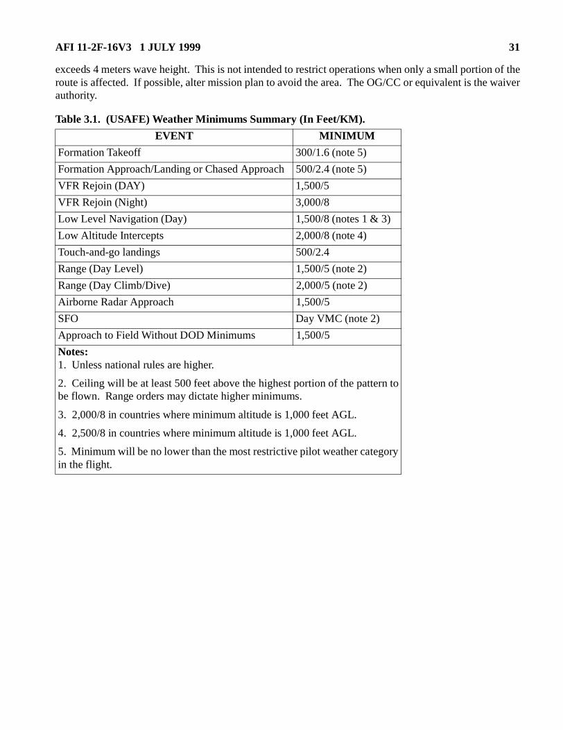
AFI 11-2F-16V3 1 JULY 1999 31
exceeds 4 meters wave height. This is not intended to restrict operations when only a small portion of theroute is affected. If possible, alter mission plan to avoid the area. The OG/CC or equivalent is the waiverauthority.
Table 3.1. (USAFE) Weather Minimums Summary (In Feet/KM).
EVENT MINIMUM
Formation Takeoff 300/1.6 (note 5)
Formation Approach/Landing or Chased Approach 500/2.4 (note 5)
VFR Rejoin (DAY) 1,500/5
VFR Rejoin (Night) 3,000/8
Low Level Navigation (Day) 1,500/8 (notes 1 & 3)
Low Altitude Intercepts 2,000/8 (note 4)
Touch-and-go landings 500/2.4
Range (Day Level) 1,500/5 (note 2)
Range (Day Climb/Dive) 2,000/5 (note 2)
Airborne Radar Approach 1,500/5
SFO Day VMC (note 2)
Approach to Field Without DOD Minimums 1,500/5
Notes:1. Unless national rules are higher.
2. Ceiling will be at least 500 feet above the highest portion of the pattern tobe flown. Range orders may dictate higher minimums.
3. 2,000/8 in countries where minimum altitude is 1,000 feet AGL.
4. 2,500/8 in countries where minimum altitude is 1,000 feet AGL.
5. Minimum will be no lower than the most restrictive pilot weather categoryin the flight.
32 AFI 11-2F-16V3 1 JULY 1999
Chapter 4
INSTRUMENT PROCEDURES
4.1. Instrument Approach:
4.1.1. The F-16 is Approach Category E. Missed approach will be accomplished in accordance withflight manual procedures. Missed approach airspeed is 200-250 KIAS.
4.1.2. Approach Category D minimums may be used at an emergency/divert airfield where no Cate-gory E minimums are published. Airfields with Category D minimums may be designated as an alter-nate (divert) airfield. Further, practice instrument approaches may be flown using Category Dminimums if VMC can be maintained throughout the procedure. Under these circumstances,Approach Category D minimums may be used provided:
4.1.2.1. A straight-in approach is flown.
4.1.2.2. The aircraft is flown at a final approach airspeed of 165 KIAS or less.
4.1.2.3. The aircraft is flown at 255 KTAS or less for the missed approach segment of theapproach. At high pressure altitudes and temperatures, 255 KTAS may not be compatible withpublished missed approach airspeeds and Category D approaches should not be flown.
4.1.3. F-16s are approved to use INS/GPS only for enroute point to point (Lat/Long) Area Navigation(RNAV). The enroute navigation period may not exceed one and one half (1.5) hours between INSupdates. An update is defined as establishing a positive position using visual references or onboardsystems. Do not fly RNAV approaches.
4.1.4. GPS approaches are not approved for USAF F-16 aircraft.
4.2. Takeoff and Join-up:
4.2.1. The flight lead must notify the appropriate ATC agency when a VMC join-up is not possibledue to weather conditions or operational requirements. Coordinate for an appropriate altitude block ortrail formation. Formation in-trail departures will comply with instructions for a nonstandard forma-tion flight as defined in FLIP. Flight lead should coordinate IFF procedures with ATC for wingmen intrail.
4.2.2. If weather is below 1,500 foot ceiling and 3 miles visibility, each aircraft/element will climb ontakeoff heading to 1,000 feet AGL before initiating any turns, except when departure instructions spe-cifically preclude compliance.
4.3. Trail Procedures:
4.3.1. General. During trail formations, basic instrument flying is the first priority and will not besacrificed when performing secondary trail tasks. Strictly adhere to the briefed airspeeds, power set-tings, altitudes, headings and turn points. If task saturation occurs, cease attempts to maintain radarcontact, immediately concentrate on flying the instrument procedure, then notify the flight lead. Theflight lead will then notify ATC.
4.3.1.1. (USAFE) For all trail formations, flight lead will request non-standard formation fromATC.
AFI 11-2F-16V3 1 JULY 1999 33
4.3.2. Trail Departures:
4.3.2.1. Use a minimum of 20 seconds takeoff spacing.
4.3.2.2. Each aircraft/element will accelerate in MIL/AB power until reaching 350 KIAS. Climbat 350 KIAS until reaching cruise Mach/TAS, unless otherwise briefed. All turns will be madeusing 30 degrees of bank.
4.3.2.3. Upon reaching 350 KIAS, the flight lead will set a pre-briefed power setting.
4.3.2.4. On departure, each aircraft/element will follow the No Radar Contact procedures until allaircraft/elements have gained radar contact and called "tied."
4.3.2.5. Each aircraft/element will maintain 2-3 mile trail during the climb, unless otherwisebriefed.
4.3.3. No Radar Contact:
4.3.3.1. The flight lead will call initiating all turns.
4.3.3.1.1. (PACAF) The flight lead will call the new heading and navaid fix when initiatingall turns to ensure all aircraft turn at the same point (EXAMPLE: Viper 11, turning right to200, 180 radial/5 DME).
4.3.3.2. During climbs and descents, each aircraft/element will call passing each 5,000 foot alti-tude increment with altitude and heading (or heading passing) until join-up, level-off or the fol-lowing aircraft/element calls "tied." In addition, each aircraft/element will call initiating anyaltitude or heading change. Acknowledgments are not required; however, it is imperative that pre-ceding aircraft/elements monitor the radio transmissions and progress of the succeeding aircraft/elements and immediately correct deviations from the departure route or planned course.
4.3.3.3. Each aircraft/element will maintain 20 seconds or 2-3 mile spacing using all available air-craft systems and navigational aids to monitor position.
4.3.3.4. Each aircraft/element will maintain at least 1,000 feet vertical separation from the preced-ing aircraft/element during the climb/descent and at level-off until radar/visual contact is estab-lished, except in instances where departure instructions specifically preclude compliance.
4.3.3.5. In the event a visual join-up cannot be accomplished on top or at level-off, the flight leadwill request 1,000 feet of altitude separation for each succeeding aircraft/element providing all air-craft can comply with MSA restrictions. If the MSA cannot be complied with, the 1,000 foot ver-tical separation may be reduced to 500 feet.
4.3.4. Radar Contact:
4.3.4.1. Each aircraft/element will call "tied" when radar contact is established with the precedingaircraft. Once all aircraft are tied, no further radio calls are required (except to acknowledge ATCinstructions) unless radar contact is lost.
4.3.4.2. In flights of three or more aircraft, every attempt should be made to use radar informationto help ensure that trail is maintained on the correct aircraft.
4.3.4.3. If radar contact is lost, a "c/s, lost contact" radio call will be made and the flight lead willdirect No Radar Contact procedures (paragraph 4.3.3.) be re-established.
4.3.5. Trail Recovery:
34 AFI 11-2F-16V3 1 JULY 1999
4.3.5.1. Trail recovery procedures must be coordinated/approved through the responsible ATCfacilities and addressed in a local operating procedure or in the unit supplement to this volume.Trail recoveries will only be accomplished at home stations/deployed locations where procedureshave been established and briefed. As a minimum, procedures will address each recovery profile,missed approach, climbout, lost contact, lost communications and desired/maximum spacingrequirements.
4.3.5.1.1. (PACAF) Trail recoveries are not authorized for initial arrival at bases other thanthe pilots' home base. Subsequent radar trail approaches at deployed locations are limited totwo aircraft maximum.
4.3.5.2. Trail recovery is limited to a maximum of four aircraft.
4.3.5.3. Trail recoveries are authorized when weather at the base of intended landing is at/abovethe highest pilot weather category in the flight or approach minimums, whichever is higher.
4.3.5.4. Trail recoveries will not terminate in simultaneous PAR or ASR approaches. Recoveriesto separate PAR/ASRs are authorized, flights will split prior to PAR/ASR final.
4.3.5.5. The flight lead will brief the flight on spacing, configuration and airspeeds. Minimumspacing between aircraft is 9,000 feet and will be maintained using on-board radar.
4.3.5.6. The flight lead will coordinate the trail recovery with ATC prior to taking spacing.
4.3.5.7. Prior to split-up, the flight lead will ensure that all wingmen have operative navigationalaids and radar.
4.3.5.8. Formation break-up will be accomplished IAW paragraph 4.4. Flight separation will beaccomplished in accordance with local ATC directives.
4.3.5.9. The formation will squawk as directed by ATC.
4.3.5.10. ATC instructions to the lead aircraft will be for the entire flight. ATC will provide radarflight following for the entire formation.
4.3.5.11. All turns are limited to a maximum of 30 degrees of bank.
4.3.5.12. Once established on a segment of a published approach, each aircraft will comply withall published altitudes and restrictions while maintaining in-trail separation.
4.3.5.13. Unless local procedures establish defined reference points for airspeed/configurationchanges, the flight lead will direct changes by radio. When so directed by the flight lead, all air-craft will simultaneously comply with the directed change.
4.3.5.14. All aircraft will report the final approach fix.
4.3.5.15. If contact is lost with the preceding aircraft, the pilot will transmit "c/s, lost contact."The preceding aircraft will respond with altitude, airspeed and heading. Altitude deconflictionwill be established and a separate clearance will be coordinated with ATC. If contact is lost afterestablished on a segment of a published approach, flight members may continue the approach, butmust confirm separation via navigation aids. If separation cannot be confirmed, aircraft will exe-cute missed approach or climbout as instructed by ATC.
4.4. Formation Break-up. Formation break-up should not be accomplished in IMC. If unavoidable,IMC break-up will be accomplished in straight and level flight. Prior to an IMC break-up, the flight lead
AFI 11-2F-16V3 1 JULY 1999 35
will confirm position and transmit attitude, altitude, airspeed, and altimeter setting. Wingmen willacknowledge and confirm good navigational aids.
4.5. Formation Penetration:
4.5.1. Formation penetrations are restricted to two aircraft when the weather at the base of intendedlanding is less than overhead traffic pattern minimums.
4.5.2. If a formation landing is intended, the wingman should be positioned on the appropriate wingprior to weather penetration.
4.6. Formation Approach. During IMC, formation flights will not change lead or wing positions below1,500 feet AGL unless on radar downwind.
4.7. Simulated Instrument Flight. Simulated instrument flight requires a qualified safety observer inthe aircraft or in a chase aircraft.
4.7.1. The pilot in either cockpit of the F-16B/D may act as safety observer when the pilot in the othercockpit is flying simulated instruments. Under these conditions, an operable intercom is required. Ifradar is operable, it will also be utilized as an aid to clear the area.
4.7.2. A chase aircraft is required in order to log simulated instrument flight when solo in an F-16.This does not preclude flying multiple approaches in VMC without a chase; however, in this case theprimary emphasis will be on the "See and Avoid" concept. Chase aircraft may move into close forma-tion on final if a formation landing is intended and simulated instrument flight is terminated.
4.8. Use of the Heads Up Display (HUD):
4.8.1. In all F-16 Block 25/30/32 aircraft and Block 40/50 aircraft with Operational Flight Program(OFP) 40T5/50T4 (TV Code 117/115) and later OFPs, the HUD may be used as a primary instrumentreference in night/IMC conditions. Do not use the HUD to recover from an unusual attitude or whileexecuting lost wingman procedures except when no other reference is available.
4.8.2. For all other F-16 Blocks and OFPs, the HUD may be used as an additional instrument refer-ence in night/IMC conditions; however, it will not be used as the sole instrument reference in theseconditions. Do not use the HUD to recover from an unusual attitude or executing lost wingman pro-cedures except when no other reference is available.
4.9. Airborne Radar Approach (ARA):
4.9.1. ARA Planning:
4.9.1.1. ARAs will be processed IAW AFI 11-230, Instrument Procedures.
4.9.1.2. ARA minimums will be no lower than ASR or TACAN minimums, whichever is higher.
4.9.1.3. IMC ARAs will only be flown in emergency situations or when the conditions in para-graph 4.9.1.4. are met.
4.9.1.4. Approved ARAs may be practiced when weather is at or above ARA minimums (asdepicted on the ARA approach plate) provided ground radar traffic advisories are available andutilized during the approach or a navigational aid (TACAN/ILS) is operational and monitored by
36 AFI 11-2F-16V3 1 JULY 1999
the pilot during the approach. If a navigational aid or ground radar is not available, ARAs will notbe practiced unless weather is at or above 1,500 foot ceiling and 3 miles visibility.
4.9.2. ARA Procedures:
4.9.2.1. Approval for the practice approach will be obtained from the controlling agency prior tocommencing the approach. The pilot will request IFR separation with radar flight following.
4.9.2.2. Fly to intercept the penetration heading prior to the fix, with no more than a 60 degreeturn to penetration heading, if possible.
4.9.2.3. Begin the penetration when over the fix, descend and level off at the altitude specified forapproach, or at 2,000 feet AGL, whichever is higher.
4.9.2.4. Identify the airfield on the radar scope and decrease radar range selection to keep the air-field near the center of the scope.
4.9.2.5. If the runway or reflectors cannot be defined, continue the approach by estimating therunway location in relation to the radar returns from the airfield.
4.9.2.6. Approximately 10 miles from the runway, descend to 1,500 feet AGL or local pattern alti-tude as specified.
4.9.2.7. At 5 miles from the runway, descend to the MDA or local pattern altitude, as specified.Descend so as to reach the MDA prior to the MAP.
4.9.2.8. Missed approach procedures will be as directed/published.
AFI 11-2F-16V3 1 JULY 1999 37
Chapter 5
AIR-TO-AIR WEAPONS EMPLOYMENT
5.1. References. AFI 11-214 contains air-to-air procedures, to include operations with live ordnance(air-to-air-missiles), applicable to all aircraft. This chapter specifies additional procedures or restrictionswhich are applicable to F-16 operations.
5.2. Simulated Gun Employment. The gun is considered SAFE and simulated gun employment isauthorized if the following conditions are met:
5.2.2. In-Flight. A trigger check must be performed with the Master Arm switch in SIMULATE andthe aircraft pointed away from other aircraft and inhabited areas. If HUD symbology reads "ARM" orSMS/MFD symbology reads "RDY," do not depress the trigger or continue with simulated weaponsemployment. Regardless of Master Arm switch position, do not perform a trigger check with a "hot"gun.
5.3. Maneuvering Limitations:
5.3.1. Negative "G" guns jink-out maneuvers are prohibited.
5.3.2. Minimum airspeed during low altitude offensive or defensive maneuvering is 350 KIAS.
5.3.3. All CAT 1 configurations are authorized for unlimited maneuvering, as defined by AFI 11-214.
5.3.4. (PACAF) Continuation training high-aspect BFM Training: A dedicated "fighter" and "train-ing aid" must be clearly identified for each engagement. The "fighter" will have some kind of advan-tage (power, G available, lead turn advantage at the merge). Syllabus (MQT/FLUG/IPUG)high-aspect BFM will be conducted IAW the appropriate syllabus.
38 AFI 11-2F-16V3 1 JULY 1999
Chapter 6
AIR-TO-SURFACE WEAPONS EMPLOYMENT
6.1. References. AFI 11-214 contains air-to-surface procedures applicable to all aircraft. This chapterspecifies procedures or restrictions applicable to F-16 operations. Qualification and scoring criteria arecontained in AFI 11-2F16V1.
6.2. Off-Range Attacks. With expendable stores (bombs, external fuel tanks, TERs carted at the pylon,etc) loaded on the aircraft, simulated weapons will be loaded (zero quantity) in the SMS/MFD only onempty or uncarted/unexpendable stations. EXCEPTION: When loaded, captive Maverick and HARMmissiles may be selected. The Master Arm switch will be confirmed in OFF or SIMULATE prior to thefirst attack.
6.2.1. (PACAF) Flight leads will verbally confirm all flight members have the Master Arm switch inOFF or SIMULATE and an empty weapons or uncarted/unexpendable station is selected on the SMSprior to the attack.
6.2.2. AFI 11-214 and the following apply:
6.2.2.1. Do not conduct off-range simulated weapons employment with hung ordnance aboard theaircraft.
6.2.2.2. Do not conduct off-range simulated weapons employment with live ordnance (except 20mm) aboard the aircraft.
6.3. Weather Minimums. Basic weather minimums established in AFI 11-214 apply. In no case will theceiling be lower than 2,000 feet AGL for climbing or diving deliveries, or 1,500 feet AGL for level deliv-eries.
6.5. Night Weapons Delivery/Range Operations. All procedures in AFI 11-214 apply.
6.5.1. Compute a MSA for the entire bombing pattern.
6.5.2. Do not exceed 135 degrees of bank when returning to the low altitude structure following prac-tice/actual night weapons deliveries.
6.5.3. (PACAF) For non-LANTIRN (non-TFR) missions, the minimum altitude for night weaponsdelivery is 2,000 feet AGL.
6.6. LANTIRN Weapons Delivery/Range Operations. All procedures in AFI 11-214 apply.
6.6.1. If CARA ALOW and/or LIS altitude advisory warnings are used for altitude cues on mediumaltitude weapons deliveries, care must be taken to reset them as appropriate when descending into thelow-level structure.
6.6.2. The pilot will perform no duties (i.e., adjusting designation cursor on targeting pod) other thanmaintaining aircraft control from the initial pull-up during the performance of a night weapons deliv-
AFI 11-2F-16V3 1 JULY 1999 39
ery safe escape maneuver or during a night climbing delivery which employs a descent back to lowaltitude until the aircraft is recovered back within TFR limits and TFR indications are adequate to con-tinue safe low altitude operations.
6.7. Target Identification. Pilots must positively identify the target prior to weapons release. Achievepositive identification by either visually acquiring the target or by confirming target location throughvalid on-board/off-board cues. These cues include radar, GPS, marking rounds, IR Maverick lock-on, IRpointers or NVG compatible marking devices. Pilots should exercise caution and possess a high level oftarget situational awareness when relying on a single target cue to confirm target location.
6.8. Live Ordnance Procedures:
6.8.1. Refer to AFI 11-214.
6.8.2. Do not make simulated weapon delivery passes on targets occupied by personnel.
6.8.3. When Ground Controllers are operating on Class B/C ranges the following procedures apply:
6.8.3.1. All pilots will be familiar with applicable range weapons delivery procedures, appropri-ate targets and weapons footprints.
6.8.3.2. Ground personnel locations will be briefed and acknowledged by all pilots.
6.8.3.3. Pilots will not expend ordnance if any doubt exists as to the ground personnel or intendedtarget locations.
6.9. Strafe Procedures. To prevent accidental gun firing, pilots will not squeeze the trigger to the firstdetent, i.e. to turn the camera on, until they actually intend to fire the gun. This restriction only applieswhen the gun is armed and selected.
40 AFI 11-2F-16V3 1 JULY 1999
Chapter 7
ABNORMAL OPERATING PROCEDURES
7.1. General. Follow the procedures in this chapter when other than normal circumstances occur. Theseprocedures do not supersede procedures contained in the flight manual.
7.1.1. Do not accept an aircraft for flight with a malfunction which is addressed in the emergency/abnormal procedures section of the flight manual until appropriate corrective actions have beenaccomplished.
7.1.2. Do not fly an aircraft with a tripped engine monitoring system (EMS) Go-No-Go indicators(Bit Balls) until it has been approved or cleared by maintenance. Verify that the appropriate technicalorder fault tree analysis has been accomplished.
7.1.3. Do not taxi an aircraft with nosewheel steering, brake system, or generator malfunctions /fail-ures. F-16C/D aircraft may be taxied with a single generator failure (main or standby) if the othergenerator is operating normally.
7.1.4. Do not fly an aircraft at night or in IMC if the INS dumps during the EPU check and an INSbattery warning PFL/MFL has occurred (F-16A/B: INS 026; F-16C/D: INS BATT WARN/INS 029).Although Block 50/52 aircraft do not have an inertial navigation unit (INU) battery, the PFL/MFLmay indicate impending aircraft battery failure, therefore, the above procedures are still valid.
7.1.5. Once a malfunctioning aircraft system is isolated, that system will not be used again unless itsuse in a degraded mode is essential for recovery. Do not conduct ground or in-flight trouble-shootingafter flight manual emergency procedures are completed.
7.1.6. In the F-16B/D, the pilot in command is primarily responsible for handling in-flight emergen-cies. The additional pilot will confirm that all critical action procedures have been accomplished andwill provide checklist assistance at the request of the pilot in command.
7.1.7. (PACAF) For actual/perceived flight control malfunctions, pilots will cease/terminate maneu-vering and take appropriate action. If the flight control problem was due to crew/passenger stick orrudder interference, the pilot will take positive action to ensure no further control interference occurs.
7.1.8. (PACAF) When a fuel imbalance is greater than dash one limits, terminate tactical maneuver-ing and investigate. If the fuel problem was caused by a slow feeding external or internal fuel tankthat can be corrected, vice a fuel system failure, the mission may continue IAW dash one guidance. Ifthe fuel imbalance cannot be corrected terminate the mission. Instruments, deployment missions,level weapons deliveries and straight through non-maneuvering intercepts are authorized to reducegross weight.
7.2. Ground Aborts:
7.2.1. If a flight member aborts prior to takeoff, the flight lead will normally renumber the flight tomaintain a numerical call sign sequence. Flight leads will advise the appropriate agencies of suchchanges.
7.2.2. A flight of two or more aircraft with only one designated flight lead in the formation musteither sympathetically abort or proceed on a pre-briefed single-ship mission should the flight leadabort.
AFI 11-2F-16V3 1 JULY 1999 41
7.2.3. Pilots who do not takeoff with the flight may join the flight at a briefed rendezvous point priorto a tactical event or may fly a briefed alternate single ship mission. If a join-up is to be accomplishedon an air-to-ground range, all events will be terminated until the joining aircraft has achieved properspacing.
7.3. Takeoff Aborts:
7.3.1. If an abort occurs during takeoff roll give call sign and state intentions when practical. Follow-ing aircraft will alter takeoff roll to ensure clearance or abort takeoff if adequate clearance cannot bemaintained. The phrase "Cable, Cable, Cable" will be used to indicate a departure-end cable arrest-ment. The phrase "Barrier, Barrier, Barrier" will be used to indicate a departure-end net arrestment.Local procedures will address net barrier raising procedures.
7.3.2. When aborting above 120 KIAS, or hot brakes are suspected, declare a ground emergency. Taxithe aircraft to the designated hot brake area and follow hot brake procedures.
7.3.3. If aborting at or above 100 knots, lower the hook. If aborting below 100 knots, the tailhookshould be lowered if there is any doubt about the ability to stop on the remaining runway.
7.4. Air Aborts:
7.4.1. If an abort occurs after takeoff, all aircraft will maintain their original numerical call sign.
7.4.2. Aborting aircraft with an emergency condition will be escorted to the field of intended landing.When other than an emergency condition exists, the flight lead will determine if an escort for theaborting aircraft is required.
7.4.3. The mission will be aborted, regardless of apparent damage or subsequent normal operation,for any of the following:
7.4.3.1. Birdstrike/Foreign Object Damage.
7.4.3.2. Over-G. The aircraft will land as soon as practical out of a straight-in approach.
7.4.3.3. Flight control system anomalies. This does not include flight control system lights thatreset IAW flight manual procedures. This does include uncommanded departures from controlledflight.
7.4.3.4. Engine flameout/stagnation or shutdown.
7.4.4. Report all engine anomalies during maintenance debriefing.
7.5. Radio Failure:
7.5.1. Formation:
7.5.1.1. A pilot who experiences total radio failure while in close or route formation will maneu-ver within close/route parameters to attract the attention of another flight member and give theappropriate visual signals. The mission should be terminated as soon as practical and the NORDOaircraft led to the base of intended landing or a divert base. A formation approach to a drop-off onfinal should be performed unless safety considerations dictate otherwise.
7.5.1.2. If flying other than close/route formation when radio failure occurs, the NORDO aircraftshould attempt to rejoin to a route position at approximately 500 feet on another flight member.
42 AFI 11-2F-16V3 1 JULY 1999
The NORDO aircraft is responsible for maintaining clearances from other flight members until hispresence is acknowledged by a wingrock, signifying clearance to join. Once joined, the NORDOaircraft will give the appropriate visual signals. If pre-briefed, the NORDO aircraft may proceedto a rendezvous point and hold. If no one has rejoined prior to reaching bingo fuel, the NORDOaircraft should proceed to the base of intended landing or a divert base. Aircraft experiencing anydifficulty/emergency in addition to NORDO will proceed as required by the situation.
7.5.2. Surface Attack NORDO Procedures:
7.5.2.1. Class A and Manned Class B Ranges:
7.5.2.1.1. Attempt contact with the RCO on the appropriate back-up frequency.
7.5.2.1.2. If contact cannot be re-established, make a pass by the range control tower on theattack heading while rocking wings and turn in the direction of traffic. The flight lead willdirect another flight member to escort the NORDO to a recovery base or rejoin the flight andRTB.
7.5.2.1.3. If the NORDO aircraft has an emergency, make a pass by the range control tower, ifpractical, on the attack heading while rocking wings, turn opposite the direction of traffic, andproceed to a recovery base. The flight lead will direct a flight member to join-up and escortthe emergency aircraft.
7.5.2.2. Unmanned Class B and Class C Ranges:
7.5.2.2.1. Make a pass on the target maintaining normal pattern spacing, if possible, whilerocking wings. The flight lead will direct another flight member to escort the NORDO aircraftto a recovery base or rejoin the flight in sequence and recover. If the NORDO has an emer-gency, if practical, will make a pass on the target maintaining normal pattern spacing, rockingwings, turn opposite direction of traffic and proceed to a recovery base. The flight lead willdirect a flight member to join-up and escort the emergency aircraft.
7.5.2.3. Unexpended Ordnance. If radio failure occurs and circumstances preclude landing withunexpended ordnance, safe jettison of ordnance may be accomplished provided the following con-ditions are met:
7.5.2.3.1. The NORDO aircraft joins on another flight member which has radio contact withthe RCO and the remainder of the flight.
7.5.2.3.2. Stores jettison visual signals specified in AFI 11-205 are relayed to the NORDOaircraft to initiate jettison.
7.5.3. DART/Missile Firing NORDO Procedures:
7.5.3.1. Aircraft will not fire without two-way radio contact.
7.5.3.2. If radio failure occurs, safe the armament switches, join on another member of the flightor the tow aircraft, IAW paragraph 7.5.1.
7.5.3.3. DART tow aircraft experiencing radio failure will rock wings and continue the turn if anattack is in progress. The flight lead of the attacking aircraft will join on the tow's wing. Remainclear of the DART in the event it is cut. The tow pilot will use standard hand signals to indicatehis difficulty. The flight lead will signal when the DART is cleared for cut with a slicing motionacross the throat. After the DART is away and the flight lead determines there is no remaining
AFI 11-2F-16V3 1 JULY 1999 43
cable, he will take the lead, RTB with the tow aircraft on the wing, advise the tower of theNORDO and establish the appropriate landing pattern. If cable remains, follow local procedures.
7.5.4. NORDO Recovery:
7.5.4.1. The procedures in AFI 11-205 and FLIP apply.
7.5.4.2. If a formation straight-in approach is flown and a go-around becomes necessary, thechase will go-around, pass the NORDO aircraft and rock his wings. The NORDO aircraft willgo-around, if the situation allows. If the NORDO aircraft is in formation as a wingman, the leaderwill initiate a gentle turn into the wingman and begin the go-around.
7.5.4.3. If the NORDO aircraft intends to make an approach-end arresting gear engagement, hewill signal the escorting aircraft by extending the tailhook. If the NORDO aircraft is not escorted,the pilot will fly a straight-in approach flashing the landing light on final to signal the tower/ROM.
7.6. Severe Weather Penetration. Do not attempt flight through severe weather. If unavoidable, flightsshould split-up and obtain separate clearances prior to severe weather penetration.
7.7. Lost Wingman Procedures. In any lost wingman situation, immediate separation of aircraft isessential. Upon losing sight of the leader, or if unable to maintain formation due to spatial disorientation(SD), the wingman will simultaneously execute the applicable lost wingman procedures while transition-ing to instruments. Refer to paragraph 7.8. for specific SD considerations. Smooth application of controlinputs is imperative to minimize the effects of SD. Once lost wingman procedures have been executed,permission to rejoin the flight must be obtained from the flight lead.
7.7.1. Two- or Three-Ship Flights:
7.7.1.1. Wings-Level Flight. In wings-level flight (climb, descent or straight and level) simulta-neously inform the leader and turn away using 15 degrees of bank for 15 seconds, then resumeheading and obtain separate clearance.
7.7.1.2. Turns:
7.7.1.2.1.Outside the Turn. Reverse the direction of turn using 15 degrees of bank for 15seconds and inform the leader. Continue straight ahead to ensure separation prior to resumingthe turn. Obtain a separate clearance.
7.7.1.2.2.Inside the Turn. Momentarily reduce power to ensure nose-tail separation andinform the flight lead to roll out of the turn. Maintain angle of bank to ensure lateral separationand obtain separate clearance. The leader may resume turn only when separation is ensured.
7.7.1.2.3.NOTE: If in three-ship echelon, refer to four-ship lost wingman procedures.
7.7.1.3. Precision/Non-precision Final. The wingman will momentarily turn away to ensureclearance, inform lead, and commence the published missed approach procedure while obtaininga separate clearance from approach control.
7.7.1.4. Missed Approach. The wingman will momentarily turn away to ensure clearance,inform lead, and continue the published or assigned missed approach procedure while climbing to500 feet above missed approach altitude. Obtain a separate clearance from approach control.
44 AFI 11-2F-16V3 1 JULY 1999
7.7.2. Four-Ship Flights. If only one aircraft in the flight becomes separated, the previous proce-dures will provide safe separation; however, since it is impossible for number 4 to immediately ascer-tain that number 3 still has visual contact with the leader, it is imperative that number 4's initial actionbe based on the assumption that number 3 has also become separated. Numbers 2 and 3 will followthe procedures outlined above. Number 4 will follow the appropriate procedure listed below:
7.7.2.1. Wings-Level Flight. Simultaneously inform the leader and turn away using 30 degreesof bank for 30 seconds, then resume heading and obtain separate clearance.
7.7.2.2. Turns:
7.7.2.2.1.Outside the Turn. Reverse direction of turn using 30 degrees of bank for 30 sec-onds to ensure separation from lead and number 3 and obtain separate clearance.
7.7.2.2.2.Inside the Turn. Momentarily reduce power to ensure nose-tail separation andincrease bank angle by 15 degrees. Inform the leader to roll out. Obtain separate clearance.Leader will resume turn only when separation is ensured.
7.7.3. Acknowledgment. The flight lead should acknowledge the lost wingman's radio call andtransmit attitude, heading, altitude, airspeed and other parameters as appropriate. Care must be takento observe published terrain clearance limits.
7.7.3.1. (USAFE) Flight leads will be directive to ensure aircraft separation as required by the sit-uation.
7.7.4. IFF/SIF. If a wingman becomes separated and any aircraft experiences radio failure, the air-craft with the operational radio will obtain a separate clearance. The NORDO aircraft will select IFF/SIF code 7600 while proceeding with previous clearance. If an emergency situation arises along withradio failure, turn the IFF/SIF to EMERGENCY for the remainder of the flight.
7.7.5. Practice. Lost wingman procedures will be practiced only in VMC.
7.7.6. Join-Up. With flight lead permission, wingmen may rejoin if weather conditions permit and avisual join-up can be accomplished.
7.8. Spatial Disorientation. Conditions which prevent a clear visual horizon or increase pilot tasking areconducive to SD. To prevent SD, the pilot will make a conscious attempt to increase his instrumentcross-check rate. When SD symptoms are detected, the following steps will be taken until symptomsabate:
7.8.1. Single Ship:
7.8.1.1. Concentrate on flying basic instruments with frequent reference to the attitude indicator.Use heads-down instruments. Defer nonessential cockpit tasks. If flying dual, transfer control tothe other pilot.
7.8.1.2. If symptoms persist, bring aircraft to straight and level flight with reference to the attitudeindicator, conditions permitting. Maintain straight and level flight, terrain permitting, until symp-toms abate, usually 30-60 seconds. Use the autopilot if required.
7.8.1.3. If necessary, declare an emergency and advise ATC.
7.8.1.4. NOTE: It is possible for SD to proceed to the point where the pilot is unable to see, inter-pret or process information from the flight instruments. Aircraft control in such a situation is
AFI 11-2F-16V3 1 JULY 1999 45
impossible. A pilot must recognize when physiological/psychological limits have been exceededand be prepared to abandon the aircraft.
7.8.2. Formation Lead:
7.8.2.1. A flight lead with SD will advise his wingmen that he has SD and he will comply withprocedures in paragraph 7.8.1.
7.8.2.2. If possible, wingmen should confirm attitude and provide verbal feedback to lead.
7.8.2.3. If symptoms persist, terminate the mission and recover the flight by the simplest and saf-est means possible.
7.8.3. Formation Wingman:
7.8.3.1. Wingman will advise lead when disorientation makes it difficult to maintain position.
7.8.3.2. Lead will advise wingman of aircraft attitude, altitude, heading, and airspeed.
7.8.3.3. If symptoms persist, lead will establish straight and level flight for 30-60 seconds, condi-tions permitting.
7.8.3.4. If the above procedures are not effective, lead should consider passing the lead to thewingman, provided the leader will be able to maintain situational awareness from a chase position.Transfer lead while in straight and level flight. Once assuming the lead, maintain straight andlevel flight for 60 seconds. If necessary, terminate the tactical mission and recover by the simplestand safest means possible.
7.8.4. Greater Than 2-Ship Formation. Lead should separate the flight into elements to moreeffectively handle a wingman with persistent SD symptoms. Establish straight and level flight IAWparagraph 4.4. (Formation Break-up). The element with the SD pilot will remain straight and levelwhile the other element separates from the flight.
7.9. Armament System Malfunctions:
7.9.1. Inadvertent Release:
7.9.1.1. Record switch positions at the time of inadvertent release and provide to armament andsafety personnel. Record the impact point, if known.
7.9.1.2. Check armament switches safe and do not attempt further release in any mode. Treatremaining stores as hung ordnance and obtain a chase aircraft during RTB, if practical.
7.9.1.3. If remaining stores present a recovery hazard, jettison in a suitable area on a single pass,if practical.
7.9.2. Failure to Release/Hung Ordnance. If ordnance fails to release when all appropriateswitches are set, proceed as follows.
7.9.2.1. Hung Live Ordnance or Aircraft Malfunction which Precludes Further Live Weap-ons Delivery:
7.9.2.1.1. All release and fuzing switches should be noted then safed.
46 AFI 11-2F-16V3 1 JULY 1999
7.9.2.1.2. Attempt to release store(s) using an alternate delivery mode. If unsuccessful,attempt to jettison store(s) using selective jettison procedures. Lastly, consider attempting toselectively jettison the rack if ordnance is unsecure or security cannot be determined.
7.9.2.1.3. If ordnance remains on the aircraft, follow the hung ordnance recovery procedures.
7.9.2.2. Practice/Inert Ordnance:
7.9.2.2.1. Re-check switch positions and make an additional attempt to expend. If no releaseoccurs, select an alternate delivery mode in an attempt to expend.
7.9.2.2.2. If the secondary release mode fails, ordnance from other stations/dispensers may bereleased providing the aircraft will remain within symmetrical load limits.
7.9.2.2.3. If remaining stores present a recovery hazard, jettison in a suitable area on a singlepass, if practical.
7.9.2.2.4. If ordnance remains on the aircraft, follow the hung ordnance recovery procedures.
7.9.3. Hangfire/Misfire:
7.9.3.1. A missile that fires but fails to depart the aircraft is a hangfire. If this occurs, the missileshould be closely observed and safety checked by a chase pilot.
7.9.3.2. A missile that fails to fire when all appropriate switches were selected is a misfire. If thisoccurs, safe the Master Arm switch and follow the hung ordnance recovery procedures.
7.9.3.3. MAVERICK Misfire. When a misfire occurs, safe the Master Arm switch and have themissile visually checked for smoke or fire. If either exists, the missile should be jettisoned on therange. If neither is noted, another pass may be attempted. If the second attempt fails, remain dryin the pattern for 15 minutes, if able, and proceed to the recovery base following hung ordnancerecovery procedures.
7.9.4.1. Visually inspect the aircraft for damage, if practical.
7.9.4.2. Declare an emergency (not required for hung practice/inert ordnance or for live unex-pended ordnance).
7.9.4.3. Obtain a chase aircraft (if available - N/A at night) and avoid populated areas and trailformations.
7.9.4.4. Land from a straight-in approach.
7.9.5. Miscellaneous Procedures:
7.9.5.1. Pilots will not attempt to expend ordnance using a delivery system with a known weap-ons release malfunction.
7.9.5.2. When abnormal missile launch or erratic missile flight is noted after launch, the launch-ing aircraft will be visually inspected (if possible) by another pilot to determine if any damage hasoccurred.
7.10. Post Arresting Gear Engagement Procedures:
AFI 11-2F-16V3 1 JULY 1999 47
7.10.1. Do not shut down the engine unless fire/other conditions dictate or directed to do so by thearresting gear crew.
7.10.2. Raise the tailhook on the signal from the arresting crew.
7.10.3. Do not taxi until directed to do so by the arresting gear crew.
7.10.4. Further procedures will be conducted IAW local unit directives (if applicable).
7.11. In-flight Practice of Emergency Procedures:
7.11.1. Simulated Emergency Procedure. Any procedure that produces an effect which wouldclosely parallel the actual emergency, such as retarding the throttle to the degree which produces adrag equivalent to a flamed out or idle engine.
7.11.2. Aborted Takeoff Practice. All practice and/or training related to aborted takeoffs will beaccomplished in the flight simulator, Cockpit Familiarization Trainer (CFT) or (if trainer unavailable)a static aircraft.
7.11.3. Prohibited. Practice in-flight engine shutdown is prohibited.
7.11.4. Emergency Landing Patterns/Simulated Flameout (SFO). Refer to AFI 11-202V3.
7.11.4.1.Field Requirements. Practice of SFO/emergency landing patterns at active airfields isauthorized provided that crash rescue and either an active tower or a ROM (or equivalent) is avail-able and in operation.
7.11.4.1.1. (USAFE) SFOs may only be practiced at USAF F-16 bases (Aviano, Span-gdahlem, and Incirlik).
7.11.4.2.Supervisory Requirements. The pilot must be CMR/BMC. IQT pilots (includingFTU) require an IP on board the aircraft or in a chase aircraft. MQT pilots (including FTU) requirea ROM or equivalent in place, or in-flight supervision from an IP/flight lead in the pattern and ina position to monitor all patterns.
7.11.4.3.SFO Procedures:
7.11.4.3.1. SFO training will be accomplished in Day/VMC conditions only.
7.11.4.3.2. Specific procedures for conduct of SFO training will be established in letters ofagreement with appropriate agencies and published in the unit supplement to this volume.
7.11.4.3.3. The SFO pattern may be entered from any direction or altitude that will ensure theaircraft is properly configured prior to 2,000 feet AGL and in a position to safely complete theapproach.
7.11.4.3.4. An SFO will not be initiated or continued if a potential traffic pattern conflictexists which would require that the pilot divide attention between the SFO and sequencingwith traffic. In addition, SFOs should be discontinued whenever excessive maneuvering isrequired, whether as a result of a traffic conflict or when making required/perceived correc-tions. Once discontinued, a go-around will be initiated and no attempt will be made tore-enter/complete that pattern/approach.
7.11.4.3.5.Radio Calls. Calls will be made IAW local agreements or procedures. As a min-imum, the following radio calls will be made:
7.11.4.3.6. SFOs will be discontinued and a go-around initiated if airspeed drops below DashOne minimum airspeed any time between base key and the initiation of the flare or if unable toobtain wings level on final by 200 feet AGL.
7.11.4.3.7. SFOs will be flown to a low approach only.
7.12. Search and Rescue (SAR) Procedures. In the event an aircraft is lost in flight, actions must beginto locate possible survivors and initiate rescue efforts. It is imperative that all flight members aggres-sively pursue location and rescue of downed personnel even though they seem uninjured. Many downedaircrews initially suffer from shock or have delayed reactions to ejection injuries. The following proce-dures are by no means complete and should be adjusted to meet each unique search and rescue situation.Specific procedures will be detailed in the unit supplement to this volume under Section F, Abnormal Pro-cedures.
7.12.1. Squawk. Immediately terminate maneuvering using appropriate Knock-It-Off procedures.Establish a SAR commander. IFF should be placed to EMER to alert ATC/GCI of the emergency sit-uation.
7.12.2. Talk. Communicate the emergency situation and aircraft/flight intentions immediately toapplicable control agencies. Use GUARD frequency if necessary.
7.12.3. Mark. Mark the last known position of survivors/crash site using any means available.TACAN/INS position, ATC/GCI positioning or ground references should be used to identify theimmediate area for subsequent rescue efforts.
7.12.4. Separate. Remain above the last observed parachute altitudes until the position of all possi-ble survivors is determined. If visual contact with parachute is not maintained, allow 1 minute perthousand feet (16 feet per second) for parachute descent. For example, if an ejection occurs at 10,000feet AGL, the aircrew will be in the chute for approximately 10 minutes. All involved may be affectedby temporal distortion. SARCAP aircrew must take note of parachute descent times to ensure theydon't fly below the parachute altitude. This situation is more critical when visual contact with thechute is lost or hampered due to darkness or weather. Deconflict other aircraft assisting in the SAR byaltitude to preclude midair collision. Establish high/low CAPs as necessary to facilitate communica-tions with other agencies.
7.12.5. Bingo. Revise bingo fuels or recovery bases as required to maintain maximum SAR coverageover survivors/crash site. Do not overfly bingo fuel. Relinquish SAR operation to designated rescueforces upon their arrival.
7.13. Critical Action Procedures (CAPs). Critical Action Procedures are contained in Attachment 3.
AFI 11-2F-16V3 1 JULY 1999 49
Chapter 8
LOCAL PROCEDURES SUPPLEMENT
8.1. General. This supplement will be distributed to MAJCOM/NAF OPRs, as applicable. This supple-ment should not duplicate and will not be less restrictive than the provisions of this or any other publica-tion without prior authorization from the appropriate MAJCOM/NAF OPR. Specific items shouldinclude, but need not be limited to those specified in paragraph 8.2.
8.2. Local Operating Procedures. The purpose of the unit local operating procedures supplement is todocument specific procedures dictated by local flying areas, missions and/or procedures. Post the unitsupplement behind the basic volume. If requirements of this supplement are incorporated in another baseinstruction, a single page supplement will be used either referencing the base instruction, or as a cover forthe entire instruction inserted, as appropriate. This supplement is not intended to be a single source docu-ment for procedures contained in other directives or instructions. Unnecessary repetition of guidance pro-vided in other established directives should be avoided; however, reference to those directives isacceptable when it serves to facilitate location of information necessary for local operating procedures.This supplement is authorized to be issued to each F-16 pilot. MAJCOMs, or other subordinate agencies(NAF, Center, etc), may direct publications approval channels and a specific format for this supplementbased on unique flying areas, missions and/or procedures. Unless changed by MAJCOM or subordinateagency, the following procedures apply:
8.2.1. When published, units will forward copies to MAJCOM and appropriate subordinate agenciesfor review. These agencies will forward any comments and/or required changes to the unit(s), ifappropriate. The process need not delay distribution unless specified otherwise by MAJCOM or asubordinate agency. If a procedure is determined to be applicable to all F-16 units, it will be incorpo-rated into the basic volume.
8.2.2. The local procedures supplement will be organized in the following format and will include,but is not limited to the following:
8.2.2.1. Section A. Introduction.
8.2.2.2. Section B. General Policy.
8.2.2.3. Section C. Ground Operations.
8.2.2.4. Section D. Flying Operations.
8.2.2.5. Section E. Weapons Employment.
8.2.2.6. Section F. Abnormal Procedures.
8.2.2.7. Attachments. Illustrations.
8.2.3. This supplement will include procedures for the following, if applicable:
8.2.3.11. (PACAF) Environmental Restrictions. Each unit will establish local environmentalrestrictions to flight operations (i.e., winds, sea state or temperature) that are applicable to theirgeographic location. Unit commanders must weigh the risk versus the operational gain whendefining these restrictions. These restrictions will be included in the unit local operating proce-dures.
MARVIN R. ESMOND, Lt General, USAFDCS, Air and Space Operations
AFI 11-2F-16V3 1 JULY 1999 51
Attachment 1
GLOSSARY OF REFERENCES AND SUPPORTING INFORMATION
References
AFI 11-202V3, General Flight Rules
AFI 11-205, Aircraft Cockpit and Formation Flight Signals
AFI 11-209, Air Force Participation in Aerial Events
AFI 11-214, Aircrew, Weapons Director, and Terminal Attack Controller Procedures for Air Operations
AFI 11-218, Aircraft Operation and Movement on the Ground
AFI 11-230, Instrument Procedures
AFI 11-2F-16V1, F-16--Aircrew Training
AFI 11-301, Aircrew Life Support Program
AFI 11-401, Flight Management
AFI 11-404, Centrifuge Training for High-G Aircrew
AFI 33-360V1, Publications Management Program
AFI 48-123, Medical Examination and Standards
AFMAN 11-217, Instrument Flight Procedures
AFTTP 3-1V1, General Planning and Employment Considerations
AFTTP 3-1V5, Tactical Employment--F-16
AFTTP 3-3V5, Combat Aircraft Fundamentals--F-16
MCR 55-125, Preparation of Mission Planning Materials (Tactical Aircraft)
Abbreviations and Acronyms
ACBT—Air Combat Training
ACM— Air Combat Maneuver
ACMI— Air Combat Maneuvering Instrumentation
AFTTP—Air Force Tactics, Techniques, and Procedures
AGL— Above Ground Level
AGSM—Anti-G Straining Maneuver
ALOW— Automatic Low Altitude Warning
AMD— Acceleration Monitoring Device
AOA—Angle of Attack
ARA—Airborne Radar Approach
52 AFI 11-2F-16V3 1 JULY 1999
ASR—Airport Surveillance Radar
ATC—Air Traffic Control
AVTR— Airborne Video Tape Recorder
AWACS—Airborne Warning and Control System
BFM—Basic Fighter Maneuver
BMC—Basic Mission Capable
CAP—Critical Action Procedure
CARA—Combined Altitude Radar Altimeter
CFT—Cockpit Familiarization Trainer
CG—Center of Gravity
CHUM— Chart Update Manual
CMR—Combat Mission Ready
CE—Combat Edge
DACT—Dissimilar Air Combat Tactics
DLO—Desired Learning Objective
DMPI— Desired Mean Point of Impact
ECM—Electronic Counter Measure
EMCON—Emission Control
EMS—Engine Monitoring System
EOR—End of Runway
EP—Emergency Procedure
FAC—Forward Air Controller
FAC-A—Forward Air Controller-Air
FAC-G—Forward Air Controller-Ground
FAF—Final Approach Fix
FCIF—Flight Crew Information File
FE—Flight Examiner
FLCS—Flight Control System
FLIP— Flight Information Publications
FLUG—Flight Lead Upgrade Program
FOD—Foreign Object Damage
FTU—Formal Training Unit
AFI 11-2F-16V3 1 JULY 1999 53
GCI—Ground Control Intercept
GLOC—G-induced Loss of Consciousness
HARTS—Horn Awareness and Recovery Training Series
HI— High Illumination
HUD—Heads-Up Display
IFF— Identification, Friend or Foe
IFR— Instrument Flight Rules
ILS— Instrument Landing System
IMC— Instrument Meteorological Conditions
INS—Inertial Navigation System
INU— Inertial Navigation Unit
IP—Instructor Pilot or Initial Point
IPUG—Instructor Pilot Upgrade
IQT— Initial Qualification Training
IR— Instrument Route
JOAP—Joint Oil Analysis Program
KIO— Knock-It-Off
LAAF— Low Altitude Advisory Function
LANTIRN— Low Altitude Navigation and Targeting Infrared for Night
Air Combat Training (ACBT)— A general term which includes (D)BFM, (D)ACM, and (D)ACT (AFI11-214).
Air Combat Tactics (ACT)—Training in the application of BFM, ACM, and tactical intercept skills toachieve a tactical air-to-air objective.
Basic Mission Capable (BMC)—See AFI 11-2F-16V1.
Combat Edge (CE)—A positive-pressure breathing-for-G (PPG) system which provides pilots/WSOsadditional protection against high positive G accelerations experienced during flight. The system consistsof aircrew equipment (high-pressure mask, counter-pressure suit, G-suit), and aircraft equipment (oxygenregulator, G-valve, and interfacing sense line). At 5-G and above, regulated air and oxygen are suppliedto provide automatic mask tensioning, vest inflation, and positive pressure breathing to the mask.
Combat Mission Ready (CMR)—See AFI 11-2F-16V1.
Continuation Training (CT)— See AFI 11-2F-16V1.
Dissimilar ACBT (DACBT)— ACBT in conjunction with another MDS aircraft as adversary. Theconnotation (D)ACBT refers to either similar or dissimilar ACBT. These connotations correspond to allfacets of ACBT (i.e., BFM, ACM, ACT).
Flight Lead (FL)—As designated on flight orders, the individual responsible for overall conduct ofmission from preflight preparation/briefing to postflight debriefing, regardless of actual position withinthe formation. A certified 4-ship FL may lead formations and missions in excess of four aircraft, unlessrestricted by the unit CC. A 2-ship FL is authorized to lead an element in a larger formation.
Initial Qualification Training (IQT)— See AFI 11-2F-16V1.
Low Altitude Navigation and Targeting Infrared for Night (LA NTIRN)— A navigation and targetingsystem that provides tactical aircraft with a low-altitude, under-the-weather, day and night operationalcapability.
Low Altitude Training (LOWAT)— See AFI 11-2F-16V1.
Mission Qualification Training (MQT)— See AFI 11-2F-16V1
Squadron Supervisor—Squadron Commander, Asst/Operations Officers, Flight CCs (ANG and AFRConly, as designated by the OG/CC).
Addresses
HQ AFFSA/XOF1535 Command Dr, Suite D-309Andrews AFB MD 20762-7002
HQ ACC/XOFT205 Dodd Blvd, Suite 101Langley AFB VA 23665-2789
A2.1.6.17. Pilot currencies for events to be flown
A2.2. NVG Considerations Briefing Guide. This guide is meant to highlight general NVG consider-ations, and provides a reference for a basic NVG briefing. All applicable NVG considerations should beincorporated into the specific briefing for the mission being flown.
A2.2.1. Weather / Illumination:
A2.2.1.1. Civil / Nautical Twilight
A2.2.1.2. Moon Rise/Set Times / Phase / Elevation / Azimuth
A2.2.1.3. Ceiling / Visibility
A2.2.1.4. LUX / EO TDA
A2.2.1.5. Obscurants to Visibility
A2.2.2. NVG Preflight:
A2.2.2.1. Check Adjustments / Helmet Fit and Security
Air Combat Training / Intercept Briefing Guide A2.3.3.
Basic Fighter Maneuvers / Air Combat Maneuvering Briefing Guide
A2.3.4.
Escort Mission Briefing Guide A2.3.5.
DART TOW Coordination Briefing Guide A2.3.6.
DART Briefing Guide A2.3.7.
Low-Level Navigation Briefing Guide A2.3.8.
Air-to-Surface Weapons Employment Briefing Guides A. Range Mission B. Surface Attack Tactics C. SEAD / Armed RECCE / Close Air Support D. LANTIRN E. Killer Scout
A2.3.9.5.3.2. Fuel Awareness / AB Use / Consumption Rates
A2.3.9.5.3.3. Flight Path Deconfliction
A2.3.9.5.3.4.Maneuvering Limitations
AFI 11-2F-16V3 1 JULY 1999 87
A2.3.9.5.3.4.1. Airspeed and G
A2.3.9.5.3.4.2. Recognition / Prevention / Recovery from Out of Control
A2.3.9.5.3.4.3. Time to Ground Impact
A2.3.9.5.3.4.3.1. Wings Level
A2.3.9.5.3.4.3.2. Overbank / Under G
A2.3.9.5.3.5. Human Factors Considerations (i.e., Channelized Attention, Task Saturation/ Prioritization, and Complacency)
A2.3.10. Alert Briefing Guide. This guide is all inclusive and is designed to incorporate all theapplicable items from the General Briefing Guide. If a specialized mission such as air refueling isanticipated, the specific briefing guide for that mission should also be used.
A2.3.10.1. Mission Data:
A2.3.10.1.1. Time Hack
A2.3.10.1.2. Mission Data Card
A2.3.10.1.2.1. Call Signs
A2.3.10.1.2.2. Aircraft / Location / Status
A2.3.10.1.2.3. Takeoff / Landing Data (Worst Case)
A2.3.10.1.2.4. Joker / Bingo Fuel
A2.3.10.1.3. Actual / Forecast Weather
A2.3.10.1.3.1. Homebase
A2.3.10.1.3.2. Alternates
A2.3.10.1.3.3. Individual Weather Category / Mandatory Status
A2.3.10.1.4. NOTAMs
A2.3.10.1.5. FCIF / Pubs / Maps
A2.3.10.1.6. Personal Equipment
A2.3.10.1.7. Alert Packet
A2.3.10.1.7.1. Authenticators / Duress Code
A2.3.10.1.7.2. Security Procedures
A2.3.10.1.8. Airfield Status
A2.3.10.1.8.1. Actual versus Max Allowable Tailwind
A2.3.10.1.8.2. Barriers
A2.3.10.1.8.3. Navigation Aids
A2.3.10.1.8.4. Hazards to Taxi / RCR
A2.3.10.2. Ground Procedures:
88 AFI 11-2F-16V3 1 JULY 1999
A2.3.10.2.1. Aircraft / Armament Preflight
A2.3.10.2.2. Cockpit Set-Up
A2.3.10.2.3. Engine Run / Hot Preflight
A2.3.10.2.4. Crew Chief Briefing
A2.3.10.2.5. Quick Check Procedures
A2.3.10.3. Launch Procedures:
A2.3.10.3.1. Notification / UHF Frequency / Authentication Requirement
A3.1. General. The following procedures will be evaluated IAW MAJCOM guidelines. Pilots shall beable to immediately accomplish these procedures in the published sequence without reference to thechecklist. Certain steps (i.e., Stores - Jettison) maybe performed out of sequence, if conditions warrant.
A3.1.1. FIRE/OVERHEAT/FUEL LEAK (GROUND):
A3.1.1.1. Throttle - Off
A3.1.1.2. JFS - Off
A3.1.1.3. Fuel Master Switch - Off
A3.1.2. GROUND EGRESS:
A3.1.2.1. Throttle - Off
A3.1.2.2. Seat - Safe
A3.1.2.3. Belt / Kit / Harness / G-Suit - Release
A3.1.3. ABORT:
A3.1.3.1. Throttle - Idle
A3.1.3.2. Hook - Down (Above 100 Knots or If Required)
A3.1.4. AB MALFUNCTION ON TAKEOFF (TAKEOFF CONTINUED):
A3.1.4.1. Throttle - MIL
A3.1.4.2. Stores - Jettison (If Required)
A3.1.5. ENGINE FAILURE ON TAKEOFF (TAKEOFF CONTINUED):
A3.1.5.1. Zoom
A3.1.5.2. Stores-Jettison (If Possible)
A3.1.5.3. Eject
A3.1.6. ENGINE FIRE ON TAKEOFF (TAKEOFF CONTINUED):
A3.1.6.1. Climb
A3.1.6.2. Stores - Jettison (If Required)
A3.1.7. LOW THRUST ON TAKEOFF/AT LOW ALTITUDE (NON-AB):
A3.1.7.1. PW 200:
A3.1.7.1.1. EEC/BUC Switch - Off.
A3.1.7.1.2. If Thrust Is Still Insufficient:
A3.1.7.1.3. Throttle - MAX AB.
A3.1.7.1.4. If Thrust Is Still Insufficient:
AFI 11-2F-16V3 1 JULY 1999 93
A3.1.7.1.5. Throttle - MIL
A3.1.7.1.6. EEC/BUC Switch - BUC
A3.1.7.1.7. If Nozzle Fails To Close After Transferring To BUC Or If Thrust Is StillInsufficient:
A3.1.7.1.8. EEC/BUC Switch - OFF
A3.1.7.1.9. Throttle - MAX AB
A3.1.7.1.10. Stores - Jettison (If or When Required)
A3.1.7.2. GE100/129 / PW220/229:
A3.1.7.2.1. Throttle - AB.
A3.1.7.2.2. If Thrust Is Still Insufficient Or AB Does Not Light:
A3.1.7.2.3. Engine Control Switch - SEC
A3.1.7.2.4. Stores - Jettison (If Required)
A3.1.8. ENGINE FAILURE/AIRSTART:
A3.1.8.1. PW200:
A3.1.8.1.1. Zoom (If at Low Altitude)
A3.1.8.1.2. Stores - Jettison (If Required)
A3.1.8.1.3. Throttle - OFF
A3.1.8.1.4. Airspeed - As Required
A3.1.8.1.5. EEC/BUC Switch - As Required.
A3.1.8.1.6.When RPM Is Between 40-25 Percent And FTIT Is Below 700 Degrees:
A3.1.8.1.7. Throttle - IDLE
A3.1.8.1.8. JFS - Start 2 When Below 20,000 Feet and 400 KIAS
A3.1.8.2. PW220:
A3.1.8.2.1. Zoom (If At Low Altitude)
A3.1.8.2.2. Stores - Jettison (If Required)
A3.1.8.2.3. Throttle - OFF
A3.1.8.2.4. Airspeed - As Required.
A3.1.8.2.5.When RPM Is Between 50-25 Percent And FTIT Is Below 700 Degrees:
A3.1.8.2.6. Throttle - IDLE
A3.1.8.2.7. JFS - Start 2 When Below 20,000 Feet and 400 KIAS
A3.1.8.3. PW229:
A3.1.8.3.1. Zoom (If at Low Altitude)
A3.1.8.3.2. Stores - Jettison (If Required)
94 AFI 11-2F-16V3 1 JULY 1999
A3.1.8.3.3. Throttle - OFF, then Midrange
A3.1.8.3.4. Airspeed - As Required
A3.1.8.3.5. JFS - Start 2 When Below 20,000 Feet and 400 KIAS
A3.1.8.4. GE100/129:
A3.1.8.4.1. Zoom (If at Low Altitude)
A3.1.8.4.2. Stores - Jettison (If Required)
A3.1.8.4.3. Throttle - OFF, then Midrange.
A3.1.8.4.4. If A Relight Does Not Occur Before RPM Decays Below 50 Percent, Or IfBelow 10,000 Feet AGL:
A3.1.8.4.5. Engine Control Switch - SEC
A3.1.8.4.6. Airspeed - As Required
A3.1.8.4.7. JFS - Start 2 When Below 20,000 Feet and 400 KIAS
A3.1.9. OUT-OF-CONTROL RECOVERY:
A3.1.9.1. Controls - Release
A3.1.9.2. Throttle - (GE) Idle, (PW) MIL if in AB.
A3.1.9.3. If In An Inverted Deep Stall:
A3.1.9.4. Rudder - Opposite Yaw Direction (Delete this step for Block 40/42/50/52 aircraft).