+ All Categories
Home > Documents > AFNOR NF M 87 201 - Nexans designation et... · chromium silicium/nickel silicium therm o c o u p l...

AFNOR NF M 87 201 - Nexans designation et... · chromium silicium/nickel silicium therm o c o u p l...

Date post: 10-Sep-2018
Category:
Upload: truongquynh
View: 215 times
Download: 0 times
Share this document with a friend
1
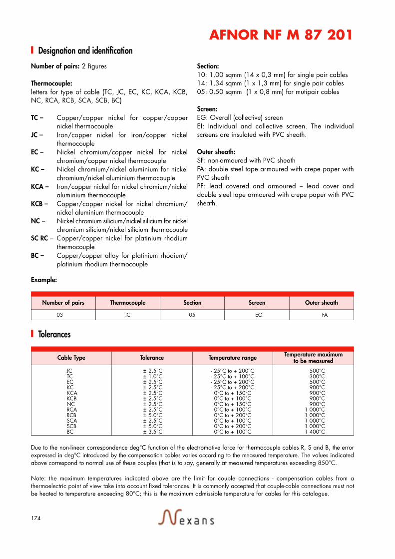
174 Number of pairs: 2 figures Thermocouple: letters for type of cable (TC, JC, EC, KC, KCA, KCB, NC, RCA, RCB, SCA, SCB, BC) TC – Copper/copper nickel for copper/copper nickel thermocouple JC – Iron/copper nickel for iron/copper nickel thermocouple EC – Nickel chromium/copper nickel for nickel chromium/copper nickel thermocouple KC – Nickel chromium/nickel aluminium for nickel chromium/nickel aluminium thermocouple KCA – Iron/copper nickel for nickel chromium/nickel aluminium thermocouple KCB – Copper/copper nickel for nickel chromium/ nickel aluminium thermocouple NC – Nickel chromium silicium/nickel silicium for nickel chromium silicium/nickel silicium thermocouple SC RC – Copper/copper nickel for platinium rhodium thermocouple BC – Copper/copper alloy for platinium rhodium/ platinium rhodium thermocouple Section: 10: 1,00 sqmm (14 x 0,3 mm) for single pair cables 14: 1,34 sqmm (1 x 1,3 mm) for single pair cables 05: 0,50 sqmm (1 x 0,8 mm) for mutipair cables Screen: EG: Overall (collective) screen EI: Individual and collective screen. The individual screens are insulated with PVC sheath. Outer sheath: SF: non-armoured with PVC sheath FA: double steel tape armoured with crepe paper with PVC sheath PF: lead covered and armoured – lead cover and double steel tape armoured with crepe paper with PVC sheath. Designation and identification Due to the non-linear correspondence deg°C function of the electromotive force for thermocouple cables R, S and B, the error expressed in deg°C introduced by the compensation cables varies according to the measured temperature. The values indicated above correspond to normal use of these couples (that is to say, generally at measured temperatures exceeding 850°C. Note: the maximum temperatures indicated above are the limit for couple connections - compensation cables from a thermoelectric point of view take into account fixed tolerances. It is commonly accepted that couple-cable connections must not be heated to temperature exceeding 80°C; this is the maximum admissible temperature for cables for this catalogue. Tolerances Number of pairs Thermocouple Section Screen Outer sheath 03 JC 05 EG FA Cable Type Tolerance Temperature range Temperature maximum to be measured JC ± 2.5°C - 25°C to + 200°C 500°C TC ± 1.0°C - 25°C to + 100°C 300°C EC ± 2.5°C - 25°C to + 200°C 500°C KC ± 2.5°C - 25°C to + 200°C 900°C KCA ± 2.5°C 0°C to + 150°C 900°C KCB ± 2.5°C 0°C to + 100°C 900°C NC ± 2.5°C 0°C to + 150°C 900°C RCA ± 2.5°C 0°C to + 100°C 1 000°C RCB ± 5.0°C 0°C to + 200°C 1 000°C SCA ± 2.5°C 0°C to + 100°C 1 000°C SCB ± 5.0°C 0°C to + 200°C 1 000°C BC ± 3.5°C 0°C to + 100°C 1 400°C Example: AFNOR NF M 87 201
Transcript

174

Number of pairs: 2 figures

Thermocouple: letters for type of cable (TC, JC, EC, KC, KCA, KCB,NC, RCA, RCB, SCA, SCB, BC)

TC – Copper/copper nickel for copper/coppernickel thermocouple

JC – Iron/copper nickel for iron/copper nickelthermocouple

EC – Nickel chromium/copper nickel for nickelchromium/copper nickel thermocouple

KC – Nickel chromium/nickel aluminium for nickelchromium/nickel aluminium thermocouple

KCA – Iron/copper nickel for nickel chromium/nickelaluminium thermocouple

KCB – Copper/copper nickel for nickel chromium/nickel aluminium thermocouple

NC – Nickel chromium silicium/nickel silicium for nickelchromium silicium/nickel silicium therm o c o u p l e

SC RC – Copper/copper nickel for platinium rhodiumthermocouple

BC – Copper/copper alloy for platinium rhodium/platinium rhodium thermocouple

Section: 10: 1,00 sqmm (14 x 0,3 mm) for single pair cables14: 1,34 sqmm (1 x 1,3 mm) for single pair cables05: 0,50 sqmm (1 x 0,8 mm) for mutipair cables

Screen:EG: Overall (collective) screenEI: Individual and collective screen. The individualscreens are insulated with PVC sheath.

Outer sheath: SF: non-armoured with PVC sheathFA: double steel tape armoured with crepe paper withPVC sheathPF: lead covered and armoured – lead cover anddouble steel tape armoured with crepe paper with PVCsheath.

Designation and identification

Due to the non-linear correspondence deg°C function of the electromotive force for thermocouple cables R, S and B, the errorexpressed in deg°C introduced by the compensation cables varies according to the measured temperature. The values indicatedabove correspond to normal use of these couples (that is to say, generally at measured temperatures exceeding 850°C.

Note: the maximum temperatures indicated above are the limit for couple connections - compensation cables from athermoelectric point of view take into account fixed tolerances. It is commonly accepted that couple-cable connections must notbe heated to temperature exceeding 80°C; this is the maximum admissible temperature for cables for this catalogue.

Tolerances

Number of pairs Thermocouple Section Screen Outer sheath

03 JC 05 EG FA

Cable Type Tolerance Temperature range Temperature maximumto be measured

JC ± 2.5°C - 25°C to + 200°C 500°CTC ± 1.0°C - 25°C to + 100°C 300°CEC ± 2.5°C - 25°C to + 200°C 500°CKC ± 2.5°C - 25°C to + 200°C 900°CKCA ± 2.5°C 0°C to + 150°C 900°CKCB ± 2.5°C 0°C to + 100°C 900°CNC ± 2.5°C 0°C to + 150°C 900°CRCA ± 2.5°C 0°C to + 100°C 1 000°CRCB ± 5.0°C 0°C to + 200°C 1 000°CSCA ± 2.5°C 0°C to + 100°C 1 000°CSCB ± 5.0°C 0°C to + 200°C 1 000°CBC ± 3.5°C 0°C to + 100°C 1 400°C

Example:

AFNOR NF M 87 201

Recommended