116
OPERATING INSTRUCTIONS AFS60 EtherNet/IP AFM60 EtherNet/IP Absolute Encoder

O P E R A T I N G I N S T R U C T I O N S
AFS60 EtherNet/IPAFM60 EtherNet/IPAbsolute Encoder

2 OPERATING INSTRUCTIONS | AFS60/AFM60 ETHERNET/IP 8014213/YFU7/2015-08-03 | SICK STEGMANN Subject to change without notice
Described product
AFS60/AFM60 EtherNet/IP
Manufacturer
SICK STEGMANN GmbHDürrheimer Str. 3678166 Donaueschingen
Germany
Legal information
This work is protected by copyright. Any rights derived from the copyright shall bereserved for SICK STEGMANN GmbH. Reproduction of this document or parts of thisdocument is only permissible within the limits of the legal determination of CopyrightLaw. Any modification, expurgation or translation of this document is prohibited withoutthe express written permission of SICK STEGMANN GmbH.
The trademarks stated in this document are the property of their respective owner.
© SICK STEGMANN GmbH. All rights reserved.
Original document
This document is an original document of SICK STEGMANN GmbH.

CONTENTS
OPERATING INSTRUCTIONS | AFS60/AFM60 ETHERNET/IP 38014213/YFU7/2015-08-03 | SICK STEGMANN Subject to change without notice
Contents
1 About this document ................................................................................ 61.1 Function of this document.......................................................................... 61.2 Target group................................................................................................ 61.3 Information depth....................................................................................... 61.4 Scope.......................................................................................................... 71.5 Abbreviations used ..................................................................................... 71.6 Symbols used.............................................................................................. 8
2 On safety..................................................................................................... 92.1 Authorised personnel.................................................................................. 92.2 Correct use ................................................................................................. 92.3 General safety notes and protective measures ........................................ 102.4 Environmental protection ......................................................................... 10
3 Product description.................................................................................113.1 Special features........................................................................................ 113.2 Operating principle of the encoder ........................................................... 12
3.2.1 Scaleable resolution................................................................ 123.2.2 Preset function ........................................................................ 123.2.3 Round axis functionality .......................................................... 13
3.3 Integration in EtherNet/IP......................................................................... 143.3.1 EtherNet/IP architecture ......................................................... 143.3.2 EtherNet/IP communication.................................................... 15
3.4 CIP object model....................................................................................... 173.4.1 Supported classes................................................................... 183.4.2 Identity Object.......................................................................... 193.4.3 Assembly Object ...................................................................... 223.4.4 Position Sensor Object ............................................................ 28
3.5 Integration and configuration options....................................................... 363.5.1 Integration in EtherNet/IP ....................................................... 363.5.2 Configuration........................................................................... 36
3.6 Configurable functions.............................................................................. 373.6.1 Saving configuration and resetting.......................................... 373.6.2 IP address................................................................................ 403.6.3 Slave Sign of Life..................................................................... 403.6.4 Code sequence........................................................................ 403.6.5 Scaling..................................................................................... 403.6.6 Steps per revolution ................................................................ 403.6.7 Total resolution/measuring range ........................................... 413.6.8 Preset function ........................................................................ 413.6.9 Velocity measuring unit ........................................................... 423.6.10 Round axis functionality .......................................................... 42
3.7 Controls and status indicators.................................................................. 43

CONTENTS
4 OPERATING INSTRUCTIONS | AFS60/AFM60 ETHERNET/IP 8014213/YFU7/2015-08-03 | SICK STEGMANN Subject to change without notice
4 Commissioning........................................................................................444.1 Electrical installation................................................................................. 44
4.1.1 Connections of the AFS60/AFM60 EtherNet/IP...................... 444.2 Settings on the hardware.......................................................................... 45
4.2.1 Setting the IP address ............................................................. 464.2.2 Triggering a preset value using the preset button ................... 47
5 Configuration with the aid of a PLC......................................................485.1 Default delivery status.............................................................................. 485.2 IP address of the encoder......................................................................... 48
5.2.1 Without DHCP server ............................................................... 485.2.2 IP address assignment via DHCP ............................................ 485.2.3 Freezing the IP address assigned............................................ 505.2.4 Checking the integration in EtherNet/IP via
RSLinx-Classic.......................................................................... 505.3 Creating a project in the controller software............................................. 505.4 Integration of the encoder as a generic module....................................... 53
5.4.1 Module settings....................................................................... 545.4.2 Download the configuration to the control system.................. 555.4.3 Checking the communication.................................................. 56
5.5 Integration and configuration with the aid of an EDS file ......................... 565.5.1 Prerequisites ........................................................................... 565.5.2 Establishing communication ................................................... 565.5.3 Configuration........................................................................... 59
5.6 Installation of the ladder routine .............................................................. 595.6.1 Importing the ladder routine.................................................... 615.6.2 Integrating in the MainRoutine as a SubRoutine..................... 665.6.3 Using the SubRoutine.............................................................. 675.6.4 Reading and changing the parameters of the encoder ........... 68
5.7 Function block .......................................................................................... 715.7.1 Prerequisites ........................................................................... 715.7.2 Importing and connecting........................................................ 71
5.8 Program examples.................................................................................... 715.8.1 Reading temperature .............................................................. 725.8.2 Setting preset value................................................................. 79
6 Configuration with the aid of the integrated web server ..................876.1 Home ........................................................................................................ 88
6.1.1 Device...................................................................................... 886.1.2 Position.................................................................................... 886.1.3 Velocity .................................................................................... 886.1.4 Temperature............................................................................ 886.1.5 Timer ....................................................................................... 89

CONTENTS
OPERATING INSTRUCTIONS | AFS60/AFM60 ETHERNET/IP 58014213/YFU7/2015-08-03 | SICK STEGMANN Subject to change without notice
6.2 Parameterization ...................................................................................... 896.2.1 Overview.................................................................................. 906.2.2 Units ........................................................................................ 916.2.3 Triggering preset...................................................................... 916.2.4 Scaling..................................................................................... 926.2.5 Round axis functionality .......................................................... 936.2.6 Changing preset value............................................................. 936.2.7 Limits....................................................................................... 946.2.8 Reset ....................................................................................... 94
6.3 Diagnostics ............................................................................................... 956.3.1 Status ...................................................................................... 956.3.2 Velocity .................................................................................... 966.3.3 Temperature............................................................................ 966.3.4 Time......................................................................................... 966.3.5 Cycles ...................................................................................... 966.3.6 Heartbeat ................................................................................ 96
6.4 Tools ......................................................................................................... 976.4.1 EDS.......................................................................................... 976.4.2 Ladder routine......................................................................... 976.4.3 Update..................................................................................... 976.4.4 Address switches..................................................................... 986.4.5 Fault header information......................................................... 98
6.5 Test notes ................................................................................................. 99
7 Fault diagnosis...................................................................................... 1007.1 In the event of faults or errors ................................................................1007.2 SICK STEGMANN support .......................................................................1007.3 Diagnostics .............................................................................................100
7.3.1 Error and status indications on the LEDs ..............................1007.3.2 Self-test via EtherNet/IP........................................................1027.3.3 Warnings, alarms and errors via EtherNet/IP........................1027.3.4 Error messages from the Allen-Bradley control system.........105
8 Annex ..................................................................................................... 1078.1 EU declaration of conformity...................................................................107
9 List of figures ........................................................................................ 108
10 List of tables.......................................................................................... 112

1 ABOUT THIS DOCUMENT
6 OPERATING INSTRUCTIONS | AFS60/AFM60 ETHERNET/IP 8014213/YFU7/2015-08-03 | SICK STEGMANN Subject to change without notice
1 About this document
Please read this chapter carefully before working with this documentation and theAFS60/AFM60 EtherNet/IP Absolute Encoder.
1.1 Function of this document
These operating instructions are designed to address the technical personnel of themachine manufacturer or the machine operator in regards to correct configuration,electrical installation, commissioning, operation and maintenance of theAFS60/AFM60 EtherNet/IP Absolute Encoder.
1.2 Target group
The operating instructions are addressed at the planners, developers and operators ofsystems in which one or more AFS60/AFM60 EtherNet/IP Absolute Encoders are to beintegrated. They also address people who initialize the use of theAFS60/AFM60 EtherNet/IP or who are in charge of servicing and maintaining thedevice.
These instructions are written for trained persons who are responsible for the instal-lation, mounting and operation of the AFS60/AFM60 EtherNet/IP in an industrialenvironment.
1.3 Information depth
These operating instructions contain information on the AFS60/AFM60 EtherNet/IPAbsolute Encoder on the following subjects:
� product features� electrical installation� commissioning and configuration
� fault diagnosis and troubleshooting� conformity
These operating instructions do not contain any information on the mounting of theAFS60/AFM60 EtherNet/IP. You will find this information in the mounting instructionsincluded with the device.
They also do not contain any information on technical specifications, dimensionaldrawings, ordering information or accessories. You will find this information in the datasheet for the AFS60/AFM60 EtherNet/IP.
Planning and using measurement systems such as the AFS60/AFM60 EtherNet/IP alsorequires specific technical skills beyond the information in the operating instructionsand mounting instructions. The information required to acquire these specific skills isnot contained in this document.
When operating the AFS60/AFM60 EtherNet/IP, the national, local and statutory rulesand regulations must be observed.
Further information
� www.odva.org

ABOUT THIS DOCUMENT 1
OPERATING INSTRUCTIONS | AFS60/AFM60 ETHERNET/IP 78014213/YFU7/2015-08-03 | SICK STEGMANN Subject to change without notice
1.4 Scope
NOTE
These operating instructions apply to the AFS60/AFM60 EtherNet/IP Absolute Encoderwith the following type codes:
� Singleturn encoder = AFS60A-xxIx262144� Multiturn encoder = AFM60A-xxIx018x12
1.5 Abbreviations used
Common Industrial Protocol
Counts per Measuring Range
Customized Number of Revolutions, Divisor = divisor of the customized number ofrevolutions
Customized Number of Revolutions, Nominator = dominator of the customized numberof revolutions
Counts Per Revolution
Dynamic Host Control Protocol
Device Level Ring
EtherNet/IP adapter developers kit = development environment for EtherNet/IPdevices
Electronic Data Sheet
Electrically Erasable Programmable Read-only Memory
Field Programmable Gate Array = electronic component that can be programmed toprovide an application-specific circuit
Input and Output Data (from the point of view of the master)
Industrial Protocol
Internet Protocol
Media Access Control
Open DeviceNet Vendor Association
Programmable Logic Controller
Transmission Control Protocol
User Datagram Protocol = connectionless network protocol
CIP
CMR
CNR_D
CNR_N
CPR
DHCP
DLR
EADK
EDS
EEPROM
FPGA
I/O
IP in EtherNet/IP
IP in TCP/IP
MAC
ODVA
PLC
TCP
UDP

1 ABOUT THIS DOCUMENT
8 OPERATING INSTRUCTIONS | AFS60/AFM60 ETHERNET/IP 8014213/YFU7/2015-08-03 | SICK STEGMANN Subject to change without notice
1.6 Symbols used
NOTE
Refer to notes for special features of the device.
LED symbols describe the state of a diagnostics LED. Examples:O The LED is illuminated constantly.Ö The LED is flashing.o The LED is off.
Instructions for taking action are shown by an arrow. Read carefully and follow theinstructions for action.
WARNINGWarning!
A warning indicates an actual or potential risk or health hazard. They are designed tohelp you to prevent accidents.
Read carefully and follow the warning notices.
O, Ö, o
► Take action …

ON SAFETY 2
OPERATING INSTRUCTIONS | AFS60/AFM60 ETHERNET/IP 98014213/YFU7/2015-08-03 | SICK STEGMANN Subject to change without notice
2 On safety
This chapter deals with your own safety and the safety of the equipment operators.
b Please read this chapter carefully before working with theAFS60/AFM60 EtherNet/IP or with the machine or system in which theAFS60/AFM60 EtherNet/IP is used.
2.1 Authorised personnel
The AFS60/AFM60 EtherNet/IP Absolute Encoder must only be installed, commis-sioned and serviced by authorized personnel.
NOTE
Repairs to the AFS60/AFM60 EtherNet/IP are only allowed to be undertaken by trainedand authorized service personnel from SICK STEGMANN GmbH.
The following qualifications are necessary for the various tasks:
Activity Qualification
Mounting � Basic technical training� Knowledge of the current safety regulations in the
workplace
Electrical installation andreplacement
� Practical electrical training� Knowledge of current electrical safety regulations� Knowledge on the use and operation of devices in the
related application (e.g. industrial robots, storage andconveyor technology)
Commissioning, operationand configuration
� Knowledge on the current safety regulations and the useand operation of devices in the related application
� Knowledge of automation systems (e.g. RockwellControlLogix Controller)
� Knowledge of EtherNet/IP� Knowledge of the usage of automation software (e.g.
Rockwell RSLogix)
Table 1: Authorised personnel
2.2 Correct use
The AFS60/AFM60 EtherNet/IP Absolute Encoder is a measuring device that is manu-factured in accordance with recognized industrial regulations and meets the qualityrequirements as per ISO 9001:2008 as well as those of an environment managementsystem as per ISO 14001:2009.
An encoder is a device for mounting that cannot be used independent of its foreseenfunction. For this reason an encoder is not equipped with immediate safe devices.
Considerations for the safety of personnel and systems must be provided by the con-structor of the system as per statutory regulations.
Due to its design, the AFS60/AFM60 EtherNet/IP can only be operated within anEtherNet/IP network. It is necessary to comply with the EtherNet/IP specifications andguidelines for setting up an EtherNet/IP network.
In case of any other usage or modifications to the AFS60/AFM60 EtherNet/IP, e.g.opening the housing during mounting and electrical installation, or in case of modifica-tions to the SICK software, any claims against SICK STEGMANN GmbH under warrantywill be rendered void.

2 ON SAFETY
10 OPERATING INSTRUCTIONS | AFS60/AFM60 ETHERNET/IP 8014213/YFU7/2015-08-03 | SICK STEGMANN Subject to change without notice
2.3 General safety notes and protective measures
WARNINGPlease observe the following procedures in order to ensure the correct and safe useof the AFS60/AFM60 EtherNet/IP!
The encoder is to be installed and maintained by trained and qualified personnel withknowledge of electronics, precision mechanics and control system programming. It isnecessary to comply with the related standards covering the technical safety stipula-tions.
The safety regulations are to be met by all persons who are installing, operating ormaintaining the devices:
� The operating instructions must always be available and must always be followed.� Unqualified personnel are not allowed to be present in the vicinity of the system
during installation and maintenance.� The system is to be installed in accordance with all applicable safety regulations
and the mounting instructions.� All work safety regulations of the applicable countries are to be followed during
installation.� Failure to follow all applicable health and safety regulations may result in injury or
damage to the system.� The current and voltage sources in the encoder are designed in accordance with
all applicable technical regulations.
2.4 Environmental protection
Please note the following information on disposal.
Assembly Material Disposal
Packaging Cardboard Waste paper
Shaft Stainless steel Scrap metal
Flange Aluminium Scrap metal
Housing Aluminium die cast Scrap metal
Electronic assemblies Various Electronic waste
Table 2: Disposal of the assemblies

PRODUCT DESCRIPTION 3
OPERATING INSTRUCTIONS | AFS60/AFM60 ETHERNET/IP 118014213/YFU7/2015-08-03 | SICK STEGMANN Subject to change without notice
3 Product description
This chapter provides information on the special features and properties of theAFS60/AFM60 EtherNet/IP. Absolute EncoderIt describes the construction and theoperating principle of the device.
b Please read this chapter before mounting, installing and commissioning thedevice.
NOTE
SICK uses standard IP technology in its products. The focus is on the availability of theproducts and services. SICK always assumes that the integrity and confidentiality ofdata and the rights related to the usage of the aforementioned products will be ad-dressed by the customer. In any case suitable security measures, e.g. network separa-tion, firewalls, anti-virus protection, patch management etc. are always to be implemen-ted by the customer to suit the situation.
3.1 Special features
Properties Sing
letu
rnen
code
r
Mul
titur
nen
code
r
Absolute Encoder in 60 mm design C C
Robust nickel coded disk for harsh environments C C
High precision and reliability C C
Large ball bearing spacing of 30 mm C C
High level of resistance to vibration C C
Optimal rotational accuracy C C
Compact design C C
Face mount flange, servo flange and blind hollowshaft
C C
18 bit singleturn resolution(1 to 262,144 steps)
C C
30 bit total resolution C
12 bit multiturn resolution(1 to 4,096 revolutions)
C
Round axis functionality C
EtherNet/IP interface (according to IEC 61784-1) C C
Supports the encoder profile 22h defined in the CIP(Common Industrial Protocol)
C C
Device Level Ring (DLR) C C
Table 3: Special features of the encoder variants

3 PRODUCT DESCRIPTION
12 OPERATING INSTRUCTIONS | AFS60/AFM60 ETHERNET/IP 8014213/YFU7/2015-08-03 | SICK STEGMANN Subject to change without notice
3.2 Operating principle of the encoder
The AFS60/AFM60 EtherNet/IP acquires the position and velocity of rotating axes andoutputs the position in the form of a unique digital numeric value. Optical acquisition ofthe rotary position value is from an internal coded disk.
The AFS60 EtherNet/IP is a singleturn encoder
Singleturn encoders are used if the absolute position of the shaft for one revolution isrequired.
The AFM60 EtherNet/IP is a multiturn encoder
Multiturn encoders are used if more than one shaft revolution must be acquiredabsolutely.
3.2.1 Scaleable resolution
The steps per revolution and the total resolution can be scaled and adapted to therelated application.
The steps per revolution can be scaled from 1 … 262,144 as an integer. The totalresolution of the AFM60 EtherNet/IP must be 2ⁿ times the steps per revolution. Thisrestriction is not relevant if the round axis functionality is activated.
3.2.2 Preset function
The position value for an encoder can be set with the aid of a preset value. I.e. theencoder can be set to any position within the measuring range. In this way, e.g., theencoder’s zero position can be adjusted to the machine’s zero point.
Figure 1: Setting a preset value
1 = Setting a preset value2 = On switching back on
On switching off the encoder, the offset, the delta between the real position value andthe value defined by the preset, is saved. On switching back on the new preset value isformed from the new real position value and the offset. Even if the position of encoderchanges while it is switched off, this procedure ensures the correct position value isstill output.
21
Actual positionvalue
Position valueafter preset
Offset
Position value afterswitching back on
Offset

PRODUCT DESCRIPTION 3
OPERATING INSTRUCTIONS | AFS60/AFM60 ETHERNET/IP 138014213/YFU7/2015-08-03 | SICK STEGMANN Subject to change without notice
3.2.3 Round axis functionality
The encoder supports the function for round axes. During this process, the steps perrevolution are set as a fraction (see section 3.6.10 on page 42). As a result, the totalresolution does not have to be configured to 2ⁿ times the steps per revolution and canalso be a decimal number (e.g. 12.5).
NOTE
The output position value is adjusted with the zero point correction, the code sequenceset and the gearbox parameters entered.
Example with transmission ratio
A rotary table for a filling system is to be controlled. The steps per revolution are pre-defined by the number of filling stations. There are nine filling stations. For the precisemeasurement of the distance between two filling stations, 1000 steps are required.
Figure 2: Example position measurement on a rotary table with transmission ratio
The number of revolutions is pre-defined by the transmission ratio = 12.5 of the rotarytable gearing.
The total resolution is then 9 × 1000 = 9000 steps, to be realized in 12.5 revolutionsof the encoder. This ratio cannot be realized via the steps per revolution and the totalresolution, as the total resolution is not 2ⁿ times the steps per revolution.
The application problem can be solved using the round axis functionality. Here thesteps per revolution are ignored. The total resolution as well as the nominator anddivisor for the number of revolutions are configured.
9000 steps are configured as the total resolution.
For the nominator for the number of revolutions 125 is configured, 10 as the divisor(125/10 = 12.5).
After 12.5 revolutions (that is after one complete revolution of the rotary table) theencoder reaches the total resolution of 9000.
125
10
Rotary table with nine filling stations
Encoder

3 PRODUCT DESCRIPTION
14 OPERATING INSTRUCTIONS | AFS60/AFM60 ETHERNET/IP 8014213/YFU7/2015-08-03 | SICK STEGMANN Subject to change without notice
Example without transmission ratio
Figure 3: Example position measurement on a rotary table without transmission ratio
The encoder is mounted directly on the rotary table. The transmission ratio is 1:1.
The rotary table has 9 filling stations. The encoder must be configured such that itstarts to count with 0 at one filling station and counts to 999 on moving to the nextfilling station position.
1000 steps are configured as the total resolution.
For the nominator for the number of revolutions 1 is configured, 9 as the divisor(1/9 revolutions = 1000).
After 1/9 revolutions of the encoder shaft there are 1000 steps, then the encoder startsto count at 0 again.
3.3 Integration in EtherNet/IP
3.3.1 EtherNet/IP architecture
EtherNet/IP and therefore also the AFS60/AFM60 EtherNet/IP use Ethernet for thetransmission technology.
The network components are generally integrated into a star or line topology.
Figure 4: Example of an EtherNet/IP network in a star topology.
1000 steps
Rotary table with nine filling stations
Encoder
Encoder Encoder
Switch
PLC
HMI

PRODUCT DESCRIPTION 3
OPERATING INSTRUCTIONS | AFS60/AFM60 ETHERNET/IP 158014213/YFU7/2015-08-03 | SICK STEGMANN Subject to change without notice
The system can also be integrated in a Device Level Ring (DLR) in order to achieve ahigher reliability and less wiring effort.
Figure 5: Example of an EtherNet/IP network in a Device Level Ring
The AFS60/AFM60 EtherNet/IP supports Device Level Ring.
3.3.2 EtherNet/IP communication
MAC address
Each AFS60/AFM60 EtherNet/IP has a factory-assigned worldwide unique MACaddress for device identification. It is used for the identification of the Ethernet node.This 6 byte device identification can not be changed and comprises the followingcomponents:
� 3 bytes manufacturer ID� 3 bytes device ID
TCP/IP and UDP/IP
EtherNet/IP uses TCP/IP or UDP/IP for the communication.
For identification the IP address is required. A fixed address is assigned to the encoderusing the address switches or the address is obtained from a DHCP server.
If the IP address is configured fix, only the least significant byte can be configured.192.168.1.xxx is preset permanently.
Additionally the subnet mask (default = 255.255.255.0) and if required a gatewaymust be configured in the network.
For real-time communication between the controller and the encoder in EtherNet/IPImplicit messaging is used. With implicit messaging, a connection is established bet-ween two devices within the CIP to transfer, e.g., I/O data such as position, velocity etc.from the encoder to the controller (see also section 3.4.4 “Position Sensor Object” onpage 28). Implicit messaging uses UDP/IP via port 2222. As a result a fast data rate isused.
Explicit messaging is used in EtherNet/IP for communication that does not need totake place in real time. Explicit messaging uses TCP/IP, it is used e.g. to transfer para-meters from the controller to the encoder (see also section 3.4.3 “Assembly Object” onpage 22).
Encoder Encoder
PLCHMI

3 PRODUCT DESCRIPTION
16 OPERATING INSTRUCTIONS | AFS60/AFM60 ETHERNET/IP 8014213/YFU7/2015-08-03 | SICK STEGMANN Subject to change without notice
Common Industrial Protocol (CIP)
EtherNet/IP uses the CIP on the process layer. Similarly as e.g. FTP is used for thetransfer of files, this protocol is used for process control.
Figure 6: CIP and other services
The AFS60/AFM60 EtherNet/IP meets the requirements of the EtherNet/IP protocolaccording to IEC 61784-1 and those of the encoder profile 22h.
The encoder is an I/O adapter in the EtherNet/IP. It receives and sends explicit mes-sages and implicit messages either cyclic or on request (polled).
EtherNet/IP communication
EtherNet/IP is based on the standard Ethernet FRAME. This contains the Ethernetheader, the Ethernet data and the Ethernet trailer. The MAC addresses of the receiver(destination address) and of the source (source address) are contained in the Ethernetheader.
Figure 7: Ethernet FRAME
Process layer
Communication layers
Physical layer
Explicit Messaging Implicit Messaging
Header
Transmission sequence
Data Field Trailer
46 … 1500 Byte

PRODUCT DESCRIPTION 3
OPERATING INSTRUCTIONS | AFS60/AFM60 ETHERNET/IP 178014213/YFU7/2015-08-03 | SICK STEGMANN Subject to change without notice
The Ethernet data field consists of several nested protocols:
� The IP datagram is transported in the user data of the Ethernet data field.� The TCP segment or the UDP datagram are transported in the user data of the IP
datagram.� The CIP protocol is transported in the user data of the TCP segment or of the UDP
datagram.
Figure 8: Ethernet data field
3.4 CIP object model
EtherNet/IP uses a so-called object model for network communication wherein allfunctions and data of a device are defined.
The most important terms are as follows:
A class contains related objects of a device, organized in instances.
An instance consists of different attributes that describe the properties of this instance.Different instances of a class have the same services and the same attributes. Theycan, however, have different attribute values.
The attributes represent the data a device provides over EtherNet/IP. These include thecurrent values of, for example, a configuration or an input. Typical attributes are confi-guration or status information.
Services are used to access classes or the attributes of a class or to generate specificevents. These services execute defined actions such as the reading of attributes.
Class Instance Attribute Value
Code 23h 1h 0Ah 3FFFFFFFh
Designation Position SensorObject
Class has oneinstance
Current positionvalue
Example
Table 4: Example CIP object model
Class
Instance
Attribute
Service
IP header CIP header
IP datagram
TCP segment or UDP datagram
CIP protocol
TCP/UDPheader CIP data

3 PRODUCT DESCRIPTION
18 OPERATING INSTRUCTIONS | AFS60/AFM60 ETHERNET/IP 8014213/YFU7/2015-08-03 | SICK STEGMANN Subject to change without notice
3.4.1 Supported classes
The AFS60/AFM60 EtherNet/IP supports the following classes of the 22h encoderprofile:
Figure 9: Supported classes
Class code Class Description Access Instances
01h Identity Object Includes all device specific data (e.g.ID, device type, device status etc.)
Get 1
02h MessageRouter Object
Includes all supported class codes ofthe encoder and the maximum num-ber of connections
Get 1
04h AssemblyObject
Assembles the data of several ob-jects to one single object. Supplies(for example) the position value ofthe encoder
Get 7
06h ConnectionManagerObject
Includes connection specific attri-butes for triggering, transport,connection type etc.
Get 1
23h PositionSensor Object
Includes all attributes for the pro-gramming of the encoder parame-ters such as the scaling
Set/Get 1
F4h Port Object Includes the available ports, portname and node address
Get 1
F5h TCP/IPInterfaceObject
Includes the attributes for TCP/IPsuch as IP address, subnet maskand gateway or acquisition of theIP address via DHCP or hardwareswitches
Set/Get 1
01h Identity
F4h
06h Connection Manager
04h Assembly
23h Position Sensor
F5hF6h
Network
02hMessageRouter
48h QoS 47h DLR

PRODUCT DESCRIPTION 3
OPERATING INSTRUCTIONS | AFS60/AFM60 ETHERNET/IP 198014213/YFU7/2015-08-03 | SICK STEGMANN Subject to change without notice
Class code Class Description Access Instances
F6h Ethernet linkobject
Includes connection specificattributes such as transmissionspeed, interface status and the MACaddress
Get 3
47h Device LevelRing (DLR)Object
Includes status attributes andconfiguration attributes of the DLRprotocol
Get 1
48h Quality ofService (QoS)Object
Contains mechanisms for processingdata streams with different priorities
Get 1
Table 5: Supported classes
3.4.2 Identity Object
The device information and device parameters are opened via the instances.
Figure 10: Connections for the Identity Object
Service code Service Description
01h Get_Attribute_All Returns the values of all attributes
0Eh Get_Attribute_Single Returns the values of one attribute
Table 6: Class services of the Identity Object
01h Identity
F4h
06h Connection Manager
04h Assembly
23h Position Sensor
F5hF6h
Network
02hMessageRouter
48h QoS 47h DLR

3 PRODUCT DESCRIPTION
20 OPERATING INSTRUCTIONS | AFS60/AFM60 ETHERNET/IP 8014213/YFU7/2015-08-03 | SICK STEGMANN Subject to change without notice
Attribute ID Access Description Data type Default value
1 Get Object revision index UINT 0001h
2 Get Highest instance numberwithin this class
UINT 0001h
3 Get Number of object instances inthis class
UINT 0001h
4 Get Optional attribute list STRUCT –
6 Get Highest existing class attributeID
UINT 0007h
7 Get Highest implemented instanceattribute
UINT 0075h
Table 7: Class attributes of the Identity Object
NOTE
Class attribute 5 is not implemented.
Service code Service Description
01h Get_Attribute_All Returns the values of all attributes
0Eh Get_Attribute_Single Returns the values of one attribute
05h Reset Resets the device:
0 = The device is re-initialized (power on).
1 = The device is re-initialized (power on) and resetto the factory settings.
Table 8: Instance Services of the Identity Object
AttributeID
Access Name Description Data type Default value
01h Get Vendor ID Manufacturer ID
0328h = SICK
UINT 0328h
02h Get DeviceType
Device profile
22h = Encoder
UINT 0022h
03h Get ProductCode
Vendor specific product code
03h = Singleturn
04h = Multiturn
UINT
04h Get Revision Contains the firmware revi-sion number in the formatXX.XX
STRUCT
Get MajorRevision
First part of the revisionnumber, e.g. 01(depending on the release)
UINT 01h
Get MinorRevision
Last part of the revisionnumber, e.g. 02(depending on the release)
UINT 02h
05h Get Status Device status flags WORD See Table 10

PRODUCT DESCRIPTION 3
OPERATING INSTRUCTIONS | AFS60/AFM60 ETHERNET/IP 218014213/YFU7/2015-08-03 | SICK STEGMANN Subject to change without notice
AttributeID
Access Name Description Data type Default value
06h Get SerialNumber
Serial number in the format
YY.WW.xxxx
Y = Year
W = Week
x = Sequential number
e. g. 0E.34.0001(depending on the release)
UDINT 0E340001h
07h Get ProductName
Product name Short_String
AFx60A-Eth/IP
68h Get Vendor Firmware version in the FPGA(e. g. 1.2.0)
UDINT 00010200h
Table 9: Instance attributes of the Identity Object
Bit Name Description Default value
0 Owned 0 = No connection to the master
1 = Connection to the master established
0
1 – Reserved 0
2 Configured 0 = Device with standard configuration
1 = No standard configuration
0
3 – Reserved 0
4 … 7 Extended Device
Status field
Vendor specific status bits See Table 11
8 MinorRecoverableStatus
0 = No error
1 = Recoverable error (device not in errorstatus)
0
9 MinorUnrecoverableStatus
0 = No error
1 = Recoverable error (device not in errorstatus)
0
10 MajorRecoverableStatus
0 = No serious error
1 = Serious error that can be reset (devicein error status)
0
11 MajorUnrecoverableStatus
0 = No serious error
1 = Serious error that cannot be reset(device in error status)
0
12 … 15 – Reserved 0000
Table 10: Bits of the instance attribute “Status”

3 PRODUCT DESCRIPTION
22 OPERATING INSTRUCTIONS | AFS60/AFM60 ETHERNET/IP 8014213/YFU7/2015-08-03 | SICK STEGMANN Subject to change without notice
Possible combinations
Bit 4 … 7
Description
0000 Device in self test
0001 Firmware update in progress
0010 At least one connection error
0011 No I/O connection established
0100 Configuration in non-volatile memory (EEPROM) failed
0101 Serious error, bit 10 or bit 11 = 1
0110 At least one connection in the “Run” operating mode
0111 At least one connection exists, all in “Idle” operating mode
1000 … 1111 Reserved
Table 11: Bits 4 to 7 of the instance attribute “Status”
3.4.3 Assembly Object
The Assembly Object allows assembling of data attributes of other objects in one singleobject. The AFS60/AFM60 EtherNet/IP supports only static assemblies of attributes.For this reason the number of instances is fixed.
Service code Service Description
01h Get_Attribute_All Returns the values of all attributes
0Eh Get_Attribute_Single Returns the values of one attribute
Table 12: Class services of the Assembly Object
Attribute ID Access Description Data type Default value
1 Get Object revision index UINT 0002h
2 Get Highest instance numberwithin this class
UINT 006Ah
3 Get Number of object instancesin this class
UINT 0007h
6 Get Highest existing classattribute ID
UINT 0007h
7 Get Highest implementedinstance attribute
UINT 0004h
Table 13: Class attributes of the Assembly Object
NOTE
Class attributes 4 and 5 are not implemented.
PRODUCT DESCRIPTION 3
OPERATING INSTRUCTIONS | AFS60/AFM60 ETHERNET/IP 238014213/YFU7/2015-08-03 | SICK STEGMANN Subject to change without notice
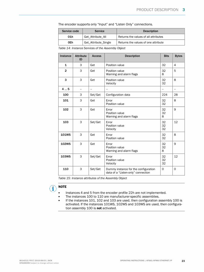
The encoder supports only “Input” and “Listen Only” connections.
Service code Service Description
01h Get_Attribute_All Returns the values of all attributes
0Eh Get_Attribute_Single Returns the values of one attribute
Table 14: Instance Services of the Assembly Object
Instance AttributeID
Access Description Bits Bytes
1 3 Get Position value 32 4
2 3 Get Position valueWarning and alarm flags
328
5
3 3 Get Position valueVelocity
3232
8
4 … 5 – – – – –
100 3 Set/Get Configuration data 224 28
101 3 Get ErrorPosition value
3232
8
102 3 Get ErrorPosition valueWarning and alarm flags
32328
9
103 3 Set/Get ErrorPosition valueVelocity
323232
12
101WS 3 Get ErrorPosition value
3232
8
102WS 3 Get ErrorPosition valueWarning and alarm flags
32328
9
103WS 3 Set/Get ErrorPosition valueVelocity
323232
12
110 3 Set/Get Dummy instance for the configurationdata of a “Listen-only” connection
0 0
Table 15: Instance attributes of the Assembly Object
NOTE
� Instances 4 and 5 from the encoder profile 22h are not implemented.� The instances 100 to 110 are manufacturer-specific assemblies.� If the instances 101, 102 and 103 are used, then configuration assembly 100 is
activated. If the instances 101WS, 102WS and 103WS are used, then configura-tion assembly 100 is not activated.

3 PRODUCT DESCRIPTION
24 OPERATING INSTRUCTIONS | AFS60/AFM60 ETHERNET/IP 8014213/YFU7/2015-08-03 | SICK STEGMANN Subject to change without notice
I/O Assembly
The I/O data are retrieved/output via instances.
Figure 11: Connections for the I/O assembly
Instance Byte Bit 7 Bit 6 Bit 5 Bit 4 Bit 3 Bit 2 Bit 1 Bit 0
0 Position value (least significant byte)
1 Position value
2 Position value
1
3 Position value (most significant byte)
0 Position value (least significant byte)
1 Position value
2 Position value
3 Position value (most significant byte)
2
4 Warning Alarm
0 Position value (least significant byte)
1 Position value
2 Position value
3 Position value (most significant byte)
4 Velocity value (least significant byte)
5 Velocity value
6 Velocity value
3
7 Velocity value (most significant byte)
01h Identity
F4h
06h Connection Manager
04h Assembly
23h Position Sensor
F5hF6h
Network
02hMessageRouter
48h QoS 47h DLR

PRODUCT DESCRIPTION 3
OPERATING INSTRUCTIONS | AFS60/AFM60 ETHERNET/IP 258014213/YFU7/2015-08-03 | SICK STEGMANN Subject to change without notice
Instance Byte Bit 7 Bit 6 Bit 5 Bit 4 Bit 3 Bit 2 Bit 1 Bit 0
0 Fault header (least significant byte, see Table 30 on page 103)
1 Fault header
2 Fault header
3 Fault header (most significant byte)
4 Position value (least significant byte)
5 Position value
6 Position value
101/101WS
7 Position value (most significant byte)
0 Fault header (least significant byte)
1 Fault header
2 Fault header
3 Fault header (most significant byte)
4 Position value (least significant byte)
5 Position value
6 Position value
7 Position value (most significant byte)
102/102WS
8 Warning Alarm
0 Fault header (least significant byte, see Table 30 on page 103)
1 Fault header
2 Fault header
3 Fault header (most significant byte)
4 Position value (least significant byte)
5 Position value
6 Position value
7 Position value (most significant byte)
8 Velocity value (least significant byte)
9 Velocity value
10 Velocity value
103/103WS
11 Velocity value (most significant byte)
Table 16: Data format of the attributes of the I/O assembly

3 PRODUCT DESCRIPTION
26 OPERATING INSTRUCTIONS | AFS60/AFM60 ETHERNET/IP 8014213/YFU7/2015-08-03 | SICK STEGMANN Subject to change without notice
Configuration Assembly
The encoder can be configured via the configuration assembly.
Figure 12: Connections for the configuration assembly
NOTE
� If you integrate the encoder as a generic module, then you can activate or not ac-tivate the configuration assembly independent of the I/O assembly instances.
� If you use the EDS file (electronic data sheet) for the encoder, then the configu-ration assembly is activated or not activated depending on the I/O assemblyinstances:
○ active with instances 101, 102 and 103○ not active with instances 101WS, 102WS and 103WS
� If the configuration assembly is activated, then it is not allowed to be empty.Otherwise in some circumstances the control system may output an error.
01h Identity
F4h
06h Connection Manager
04h Assembly
23h Position Sensor
F5hF6h
Network
02hMessageRouter
48h QoS 47h DLR

PRODUCT DESCRIPTION 3
OPERATING INSTRUCTIONS | AFS60/AFM60 ETHERNET/IP 278014213/YFU7/2015-08-03 | SICK STEGMANN Subject to change without notice
Instance Byte Bit 7 Bit 6 Bit 5 Bit 4 Bit 3 Bit 2 Bit 1 Bit 0
0 Not used
1 Not used
2 Not used
3 Not used
4 Steps per revolution CPR (least significant byte)
5 CPR
6 CPR
7 CPR (most significant byte)
8 Total resolution CMR (least significant byte)
9 CMR
10 CMR
11 CMR (most significant byte)
12 Not used cw/ccw 1)
13 Not used scf 2)
14 Not used raf 3)
15 Not used
16 Nominator for the number of revolutions CNR_N (least significant byte)
17 CNR_N
18 CNR_N
19 CNR_N (most significant byte)
20 Divisor for the number of revolutions CNR_D (least significant byte)
21 CNR_D
22 CNR_D
23 CNR_D (most significant byte)
24 Velocity measuring unit (least significant byte)
25 Velocity measuring unit (most significant byte)
26 Not used
100
27 Not used
Table 17: Data format for the attributes for the configuration assembly
NOTE
� The structure of the configuration assembly is fixed.� During the initialization of the encoder, it reads the data from the control system.� The “Heartbeat connection point” for PLC input connections, that is for the enco-
der output, must be set to 198 (see Figure 30 on page 54).� The “Heartbeat connection point” for listen-only connections must be set to 199.
1) cw = clockwise.ccw = counterclockwise.
2) scf = scaling function.3) raf = round axis functionality.

3 PRODUCT DESCRIPTION
28 OPERATING INSTRUCTIONS | AFS60/AFM60 ETHERNET/IP 8014213/YFU7/2015-08-03 | SICK STEGMANN Subject to change without notice
3.4.4 Position Sensor Object
The Position Sensor Object contains all the attributes of the encoder. All parameterscan be retrieved or set using explicit messages.
Figure 13: Connections for explicit messages to the Position Sensor Object
Service code Service Description
05h Reset Resets the encoder to the default factory settings
0Eh Get_Attribute_Single Returns the values of one attribute
15h Restore Restores all parameters last saved in non-volatilememory
16h Save Saves parameters in the non-volatile memory (seesection 3.6.1 on page 37)
Table 18: Class services of the Position Sensor Object
01h Identity
F4h
06h Connection Manager
04h Assembly
23h Position Sensor
F5hF6h
Network
02hMessageRouter
48h QoS 47h DLR

PRODUCT DESCRIPTION 3
OPERATING INSTRUCTIONS | AFS60/AFM60 ETHERNET/IP 298014213/YFU7/2015-08-03 | SICK STEGMANN Subject to change without notice
Attribute ID Access Description Data type Default value
1 Get Object revision index UINT 0002h
2 Get Highest instance numberwithin this class
UINT 0001h
3 Get Number of object instancesin this class
UINT 0001h
4 Get Optional attribute list STRUCT –
5 Get Optional services list STRUCT –
6 Get Highest existing classattribute ID
UINT 0064h
7 Get Highest implementedinstance attribute
UINT –
100 Get Firmware version Array AFx_aa.bb.dd.mm.yy
Table 19: Class attributes of the Position Sensor Object
Service code Service Description
0Eh Get_Attribute_Single Returns the values of one attribute
10h Set_Attribute_Single Sets the value of an attribute
Table 20: Instance services of the Position Sensor Object
AttributeID
Access V/NV 4) Name Description Datatype
Min.Max.
(default value)
01h Get V Number ofAttributes
Number of attributesin this class
UINT 0000hFFFFh
02h Get V AttributeList
List of the supportedattributes
Array ofBytes
–
0Ah Get V PositionValueSigned
Current positionvalue
DINT –
0Bh Get NV PositionSensorType
01h = Singleturn02h = Multiturn
UINT 0001h0002h(0002h)
0Ch Set NV DirectionCounting
Code sequence0 = Clockwise1 = Counterclockwise
BOOL (0)
0Dh Set NV Commis-sioningDiagnosticControl
Encoder self-test0 = Off1 = On
BOOL (0)
0Eh Set NV ScalingFunctionControl
Scaling0 = Off1 = On
BOOL (0)
0Fh Set NV PositionFormat
Format of the posi-tion measurement1001h = Steps
ENGUINT
(1001h)
4) V = volatile, NV = non-volatile.

3 PRODUCT DESCRIPTION
30 OPERATING INSTRUCTIONS | AFS60/AFM60 ETHERNET/IP 8014213/YFU7/2015-08-03 | SICK STEGMANN Subject to change without notice
AttributeID
Access V/NV 4) Name Description Datatype
Min.Max.
(default value)
10h Set NV Countsper Range
Number of steps perrevolution (CPR)
UDINT 00000001h00040000h(00040000h)
11h Set NV TotalMeasuringRange
Total resolution(CMR)
UDINT 00000001h40000000h(4,096 ×attribute 10h)
12h Set NV PositionMeasuringIncrement
Minimum resolution(always 1)
UDINT 00000001h00000001h
13h Set NV PresetValue
Preset value DINT 00000000hAttribute11h – 1(00000000h)
15h Get NV PositionStatusRegister
Indicates whetherthe limit set by theattributes 16h and17h is droppedbelow/exceeded.Bit 0 = Out of rangeBit 1 = Over rangeBit 2 = Under rangeBit 3 … 7 = Reserved
Byte (00h)
16h Set NV Positionlow limit
Lower limit for theposition 5)
DINT 00000000h3FFFFFFFh(00000000h)
17h Set NV Positionhigh limit
Upper limit for theposition 5)
DINT 00000000h3FFFFFFFh(3FFFFFFFh)
18h Get V VelocityValue
Current velocity. Theformat is defined bythe attributes 19hand 1Ah.
DINT 00000000hXXXXXXXXh 6)
19h Set NV VelocityFormat
Velocity unit1F04h = counts/s1F05h = counts/ms1F0Eh = turns/s1F0Fh = turns/min1F10h = turns/h
ENGUINT
(1F0Fh)
1Ah Set NV VelocityResolution
Minimum resolutionof the velocitymeasurement
DUINT (00000001h)
5) Using the lower and upper limit for the position you can realize range monitoring. This is not an electronic cam.6) The maximum velocity is dependent on the mechanical interface used, “solid shaft” or “blind hollow shaft” (see data sheet).

PRODUCT DESCRIPTION 3
OPERATING INSTRUCTIONS | AFS60/AFM60 ETHERNET/IP 318014213/YFU7/2015-08-03 | SICK STEGMANN Subject to change without notice
AttributeID
Access V/NV 4) Name Description Datatype
Min.Max.
(default value)
1Bh Set NV MinimumVelocitySetpoint
DINT (–12,000)
1Ch Set NV Maximumvelocitysetpoint
Lower/upper limit forthe velocity inturns/min 7). If thevelocity dropsbelow/exceeds thisvalue, the warningflag (attribute 2Fh) isset.
DINT (+12,000)
1Dh Get V Accelera-tion value
Current acceleration.The format is definedby the attributes 1Ehand 1Fh.
DINT 00000000hFFFFFFFFh
1Eh Set NV Accelera-tionformat
Acceleration unit0810h = counts/ms²0811h = counts/s²0812h = turns/s²0813h = rad/s²
ENGUINT
(0810h)
1Fh Set NV Accelera-tionresolution
Minimum resolutionof the accelerationmeasurement
DUINT (1)
20h Set NV MinimumAccelera-tionSetpoint
DINT (C0000001h)
21h Set NV Maximumaccelera-tionsetpoint
Lower/upper limit forthe acceleration incounts/ms² 8). If theacceleration dropsbelow/exceeds thisvalue, the warningflag (attribute 2Fh) isset.
DINT (3FFFFFFFh)
29h Get V OperatingStatus
Operating status ofthe encoder
Bit 0: Direction0 = Counting up1 = Downwardcounting
Bit 1: Scaling0 = Off1 = On
Bit 2 … 4: Reserved
Bit 5: Diagnosticson/off0 = Off1 = On
Bit 6, 7: Reserved
Byte
2Ah Get NV PhysicalResolutionSpan
Physical resolutionper revolution =18 bits
UDINT (40000h)
7) The unit changes with the velocity format (attribute ID 19h). The limits must then be converted correspondingly, e.g. 12,000 turns/min =200 turns/s.
8) The unit changes with the acceleration format (attribute ID 1Eh). The limits must then be converted correspondingly, e.g. 2 counts/ms² =2,000,000 counts/s².

3 PRODUCT DESCRIPTION
32 OPERATING INSTRUCTIONS | AFS60/AFM60 ETHERNET/IP 8014213/YFU7/2015-08-03 | SICK STEGMANN Subject to change without notice
AttributeID
Access V/NV 4) Name Description Datatype
Min.Max.
(default value)
2Bh Get NV PhysicalResolution
Number ofSpan
Physical number ofrevolutions
0001h = Singleturn1000h = Multiturn
UINT (0001h)or(1000h)
2Ch Get V Alarms Bit field with flags foralarms and errors(see Table 31: Alarms on page 104)
WORD –
2Dh Get NV SupportedAlarms
Supported alarmsand errors
WORD 3003h
2Eh Get V Alarm flag 0 = No alarm/error1 = Alarm/error
BOOL –
2Fh Get V Warnings Bit field with flags forwarnings (seeTable 32: Warningson page 105)
WORD –
30h Get NV SupportedWarnings
Supported warnings WORD 67C3h
31h Get V WarningFlag
0 = No warning1 = Warning
BOOL –
32h Get NV OperatingTime
Saved operating timein 0.1 h = 6 min
UDINT 0
33h Get NV OffsetValue
Offset value is calcu-lated on the initiali-zation of the presetfunction
DINT 00000000h
64h Get V Tempera-ture Value
Current temperaturewith ±5 accuracy
–40 to +100 °C or–40 to +212 °F
INT F060h2710h
65h Set NV Tempera-ture ValueFormat
Temperature unit1200h = °C (Celsius)1201h = °F (Fahren-heit)
ENGUINT
(1200h)
66h Set NV Tempera-tureResolution
Lowest resolution forthe temperature(°C/100 or °F/100)
UDINT (00000064h)
67h Set NV MinimumTempera-tureSetpoint
INT F060h–(F060h =–4,000)
68h Set NV MaximumTempera-tureSetpoint
Lower/upper limit forthe temperature in°C 9).If the temperaturedrops below/exceedsthis value, the war-ning flag (attribute2Fh) is set.
INT –2710h(2710h =+10,000)or(52D0h =+21,200)
9) The unit changes with the temperature value format (attribute ID 65h). The limits must then be converted correspondingly.

PRODUCT DESCRIPTION 3
OPERATING INSTRUCTIONS | AFS60/AFM60 ETHERNET/IP 338014213/YFU7/2015-08-03 | SICK STEGMANN Subject to change without notice
AttributeID
Access V/NV 4) Name Description Datatype
Min.Max.
(default value)
69h Get V Faultheader
See Table 30 onpage 103
DWORD (00000000h)
6Ah Set V SpecialEncoderFunction-alities
Bit field with flags forspecial encoderfunctions
Bit 0: Slave Sign ofLife (on/off)
Bit 1 … 7: Not used
Bit 8 … 15: Updatefactor (2 … 127)
Bit 16 … 31: Notused
DWORD (00000500h)
6Bh Get NV EncoderMotionTime
Saved motion time inseconds (is in-creased in case ofmovement)
UDINT –
6Ch Get NV EncoderOperatingTime
Saved operating timein seconds (is in-creased as soon asthe encoder is inoperation)
UDINT –
6Dh Get NV Max.velocity
Highest velocity thatthe encoder hasreached since start-up 10)
UDINT –
6Eh Get NV Max.accelera-tion
Highest accelerationthat the encoder hasreached since start-up 11)
UDINT –
6Fh Get NV Max. temp Highest operatingtemperature reachedin C°/100
UDINT –4,000
70h Get NV Min.Temp
Lowest operatingtemperature reachedin C°/100
UDINT 10,000
71h Get NV Number ofStart-ups
Number of times theencoder has beencommissioned(powered on)
UDINT –
72h Get V LEDCurrentValue
Actual internal LEDcurrent of the sensorin µA
UINT 20025,000(0)
73h Get NV Max.currentvalue
Maximum internalLED current for thesensor in µA
UINT 200
74h Get NV Min.CurrentValue
Minimum internalLED current in thesensors in µA
UINT 25,000
10) The value is output in the format defined in attribute ID 19h.11) The value is output in the format defined in attribute ID 1Eh.
3 PRODUCT DESCRIPTION
34 OPERATING INSTRUCTIONS | AFS60/AFM60 ETHERNET/IP 8014213/YFU7/2015-08-03 | SICK STEGMANN Subject to change without notice
AttributeID
Access V/NV 4) Name Description Datatype
Min.Max.
(default value)
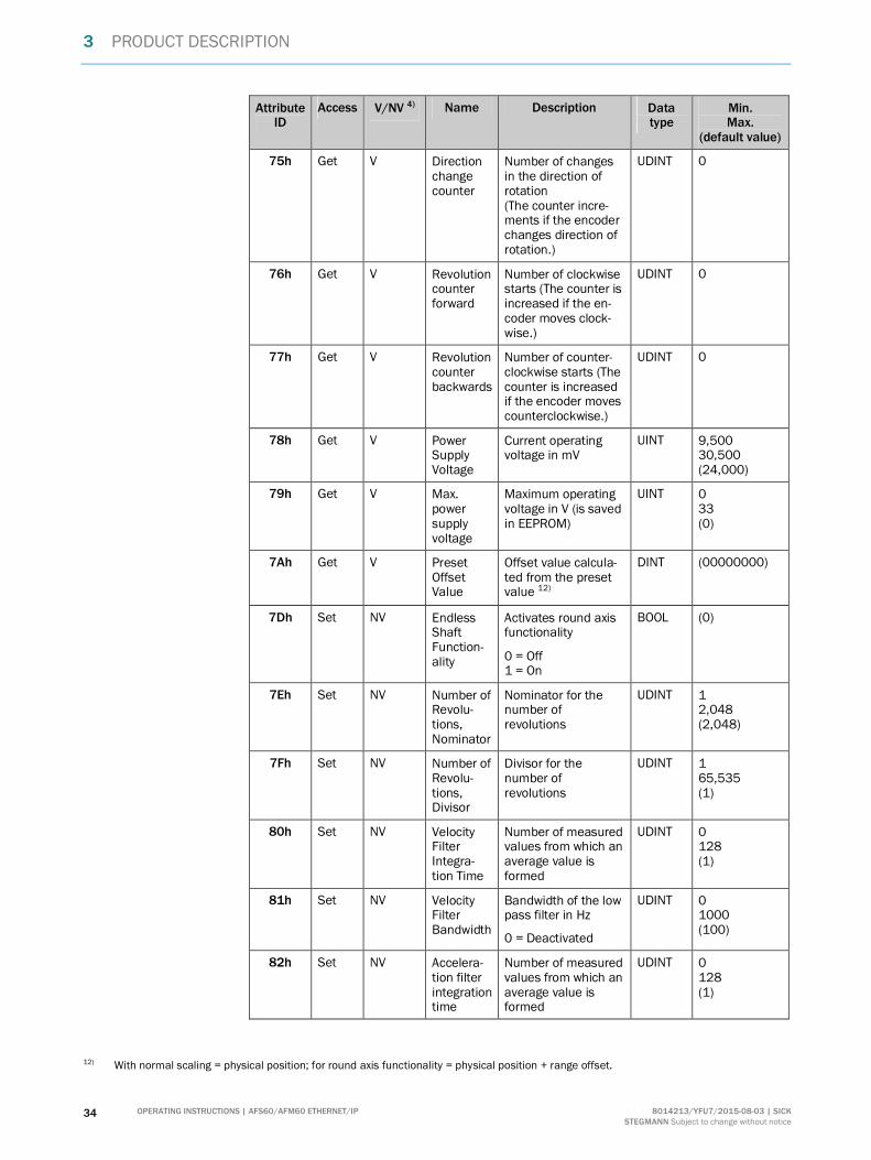
75h Get V Directionchangecounter
Number of changesin the direction ofrotation(The counter incre-ments if the encoderchanges direction ofrotation.)
UDINT 0
76h Get V Revolutioncounterforward
Number of clockwisestarts (The counter isincreased if the en-coder moves clock-wise.)
UDINT 0
77h Get V Revolutioncounterbackwards
Number of counter-clockwise starts (Thecounter is increasedif the encoder movescounterclockwise.)
UDINT 0
78h Get V PowerSupplyVoltage
Current operatingvoltage in mV
UINT 9,50030,500(24,000)
79h Get V Max.powersupplyvoltage
Maximum operatingvoltage in V (is savedin EEPROM)
UINT 033(0)
7Ah Get V PresetOffsetValue
Offset value calcula-ted from the presetvalue 12)
DINT (00000000)
7Dh Set NV EndlessShaftFunction-ality
Activates round axisfunctionality
0 = Off1 = On
BOOL (0)
7Eh Set NV Number ofRevolu-tions,Nominator
Nominator for thenumber ofrevolutions
UDINT 12,048(2,048)
7Fh Set NV Number ofRevolu-tions,Divisor
Divisor for thenumber ofrevolutions
UDINT 165,535(1)
80h Set NV VelocityFilterIntegra-tion Time
Number of measuredvalues from which anaverage value isformed
UDINT 0128(1)
81h Set NV VelocityFilterBandwidth
Bandwidth of the lowpass filter in Hz
0 = Deactivated
UDINT 01000(100)
82h Set NV Accelera-tion filterintegrationtime
Number of measuredvalues from which anaverage value isformed
UDINT 0128(1)
12) With normal scaling = physical position; for round axis functionality = physical position + range offset.

PRODUCT DESCRIPTION 3
OPERATING INSTRUCTIONS | AFS60/AFM60 ETHERNET/IP 358014213/YFU7/2015-08-03 | SICK STEGMANN Subject to change without notice
AttributeID
Access V/NV 4) Name Description Datatype
Min.Max.
(default value)
83h Set NV Accelera-tion filterbandwidth
Bandwidth of the lowpass filter in Hz
0 = Deactivated
UDINT 01000(100)
84h Set NV VelocityHysteresis
Hysteresis for thevelocity limits (attri-butes 1Bh and 1Ch)
The unit depends onattribute ID 19h.
UDINT 03FFFFFFF(0)
85h Set NV Accelera-tionhysteresis
Hysteresis for theacceleration limits(attributes 20h and21h)
The unit depends onthe attribute ID 1Eh.
UDINT 03FFFFFFF(0)
86h Set V Motiontime limit
Limit for the motiontime in seconds
UDINT 00000000hFFFFFFFFh(630,720,000)
87h Set V Powertime limit
Limit for the opera-ting time in seconds
UDINT 00000000hFFFFFFFFh(630,720,000)
88h Set V Directionchangeslimit
Limit for the numberof changes in thedirection of rotation
UDINT 00000000hFFFFFFFFh(1,000,000)
89h Set V Starts incw limit
Limit for the numberof clockwise starts
UDINT 00000000hFFFFFFFFh(1,000,000)
8Ah Set V Starts inccw limit
Limit for the numberof counterclockwisestarts
UDINT 00000000hFFFFFFFFh(1,000,000)
8Bh Set V Resetfaultheaderbit 15
Resets bit 15 in thefault header (seeTable 30 onpage 103)
Byte (00h)
Table 21: Instance attributes of the Position Sensor Object
Filter for the velocity (attribute 80h and 81h) or the acceleration (attribute 82hand 83h)
The filters are used to smooth the raw velocity and acceleration values.
NOTE
The filters are applied in the following sequence:
� integration time filter for the velocity (80h) or acceleration (82h)� low pass filter for the velocity (81h) or acceleration (83h)

3 PRODUCT DESCRIPTION
36 OPERATING INSTRUCTIONS | AFS60/AFM60 ETHERNET/IP 8014213/YFU7/2015-08-03 | SICK STEGMANN Subject to change without notice
The filter with the attribute 80h forms an average value from the measured velocityvalues. The filter with the attribute 82h forms an average value from the measuredacceleration values:
� With a configured value of 1 the average value is formed from 2 measured values.� With a configured value of 128 the average value is formed from 129 measured
values.
The filter with the attribute 81h forms a low pass for the measured velocity values. Thefilter with the attribute 83h forms a low pass for the measured acceleration values:
� From the factory this is configured to 100 Hz. I.e. only velocity and accelerationvalues £ 100 Hz are taken into account.
3.5 Integration and configuration options
The encoder can be integrated in EtherNet/IP in various ways and configured depen-ding on the integration.
3.5.1 Integration in EtherNet/IP
The encoder can be integrated in EtherNet/IP:
� as Generic Modules (see section 5.4 on page 53):
You enter all module settings manually.
� with the aid of an EDS file (see section 5.5 on page 56):
The module settings for the encoder AFS60/AFM60 EtherNet/IP are alreadypredefined.
3.5.2 Configuration
The following options are available to configure the encoder:
� the configuration assembly� the controller tags in the controller organizer� the web server integrated in the encoder
Case 1: On integration as a generic module
If you have integrated the encoder as a generic module, then you can configure itdepending on the Connection Parameters entered.
� If the configuration assembly is activated in Connection Parameters, then youmust use the configuration assembly for configuration (see section 5.4.1 onpage 54).In addition you can configure the parameters that are not contained in the confi-guration assembly using the web server integrated in the encoder.
� If the configuration assembly is not activated in Connection Parameters, you canuse the web server to configure all parameters (see chapter 6 on page 87).
NOTE
If the configuration assembly is active, all the parameters entered there overwrite theparameters that have been configured using the web server.

PRODUCT DESCRIPTION 3
OPERATING INSTRUCTIONS | AFS60/AFM60 ETHERNET/IP 378014213/YFU7/2015-08-03 | SICK STEGMANN Subject to change without notice
Case 2: On integration with the aid of the EDS file
If you have integrated the encoder with the aid of the EDS file, then you can configure itdepending on the selected I/O assembly instances (see Table 15 on page 23).
� If you use the instances 101, 102 or 103, then the configuration parameters canbe configured in the Controller Tags. In addition you can use the web server toconfigure the parameters that are not contained in the configuration assembly.
� If you use the instances 101WS, 102WS or 103WS, then you can use the webserver to configure the parameters.
Case 3: On usage of the ladder routine for the configuration mapping
A ladder routine is available for mapping the configuration data for theAFS60/AFM60 EtherNet/IP (see section 5.6 on page 59).
If the ladder routine is used for mapping, and you use the instances 101WS, 102WS or103WS (see Table 15 on page 23), then the encoder can be configured from the con-trol system (in the Controller Tags) and also with the aid of the web server.
NOTE
In cases 1 and 2 the parameters are configured offline and written to the encoder andactivated on changing to the online mode.
If the ladder routine is used (case 3), then changes to the configuration are effectiveimmediately also in the online mode!
Parameter changes via the web server are applied immediately on the control systemside and displayed. Parameter changes via the control system are applied immediately.However, to display them in the web browser you must refresh the related page.
WARNINGBefore changing the configuration, check whether there is a hazard from themachine or system in which the encoder is integrated!
The ladder routine offers the possibility to change the parameter data during operation,i.e. while the control system is in the online mode.
The change to the configuration therefore has immediate effects on the data outputfrom the encoder. This change could cause an unexpected reaction that may result in ahazard for persons or damage to the system or other items.
3.6 Configurable functions
3.6.1 Saving configuration and resetting
The configuration memory in the AFS60/AFM60 EtherNet/IP is divided into three. Thefollowing table shows the functions of the memory types.
Memory type Function
Volatile memory During operation the encoder operates with the values in thevolatile memory. Modified parameters are initially written to thevolatile memory. These data are lost on switching off.
Non-volatile memory On switching on, the encoder loads the values from the non-volatile memory into the volatile memory.
Default factory settings Contains the pre-set values from the factory.
Table 22: Configuration memory — functions of the different types of memory

3 PRODUCT DESCRIPTION
38 OPERATING INSTRUCTIONS | AFS60/AFM60 ETHERNET/IP 8014213/YFU7/2015-08-03 | SICK STEGMANN Subject to change without notice
Figure 14: Configuration memory
Reset: Reset to the default factory settings
b Set the address switches to 888 (see Figure 18 on page 46).b Press the preset push-button for longer than 5 seconds.
Or:
b Use the class service Reset (service code 05h) in the Position Sensor Object (23h)and set the data to 01h.
The parameters for the Position Sensor Object are reset to the factory settings.Table 23 on page 39 shows which parameters are reset to which value.
Restore: Reset to the values in the non-volatile memory
Each time the encoder is switched on the values for the Position Sensor Object areread from the non-volatile memory.
b Use the class service Restore (service code 15h) in the Position Sensor Object ifyou want to read the parameters from the non-volatile memory during operation.The parameters that have been changed since switching on but not yet saved arelost.
Save: Save parameters in the non-volatile memory
b Use the class service Save (service code 16h) in the Position Sensor Object.
The parameters are saved in the non-volatile memory. Table 23 on page 39 showswhich parameters are saved.
Parameters that are saved or reset
Attribute ID in theposition sensor object
Parameter Default factory setting
0Ch Code sequence cw
0Eh Scaling Off
10h Steps per revolution 262,144
11h Total resolution 1,073,741,824
Saved defaultfactory setting
Non-volatile memoryVolatile memory
Parameterization
Save
Restore
Reset + Data 01hActs on encoder

PRODUCT DESCRIPTION 3
OPERATING INSTRUCTIONS | AFS60/AFM60 ETHERNET/IP 398014213/YFU7/2015-08-03 | SICK STEGMANN Subject to change without notice
Attribute ID in theposition sensor object
Parameter Default factory setting
13h Preset value 0
16h Lower limit for the position 0
17h Upper limit for the position 1,073,741,823
19h Velocity unit Turns/min
1Bh Lower limit for the velocity –12,000
1Ch Upper limit for the velocity 12,000
1Eh Acceleration unit Counts/ms²
20h Lower limit for the acceleration –1,073,741,823
21h Upper limit for the acceleration 1,073,741,823
65h Temperature unit °C
7Dh Round axis functionality Off
7Eh Nominator for the number of revolutions 2,048
7Fh Divisor for the number of revolutions 1
80h Number of measured values from whichan average value is formed
1
81h Bandwidth of the low pass filter 100
82h Number of measured values from whichan average value is formed
1
83h Bandwidth of the low pass filter 100
84h Hysteresis for the velocity limits 0
85h Hysteresis for the acceleration limits 0
86h Limit for the motion time in seconds 630,720,000
87h Limit for the operating time in seconds 630,720,000
88h Limit for the number of changes in thedirection of rotation
1,000,000
89h Limit for the number of clockwise starts 1,000,000
8Ah Limit for the number of counterclockwisestarts
1,000,000
Table 23: Parameters that are saved or reset
NOTE
The following parameters are not reset:
� motion time� operating time� lower limit for the temperature� upper limit for the temperature� maximum voltage supply

3 PRODUCT DESCRIPTION
40 OPERATING INSTRUCTIONS | AFS60/AFM60 ETHERNET/IP 8014213/YFU7/2015-08-03 | SICK STEGMANN Subject to change without notice
3.6.2 IP address
For identification of the encoder in the EtherNet/IP, the IP address is required. Thisaddress is obtained for the encoder from a DHCP server (see section 5.2.2 on page 48)or a fixed address is set using address switches (see section 4.2.1 on page 46).
� If the IP address is obtained via DHCP, then any address range is possible.� If the IP address is set via address switches, the address range is defined as
192.168.1.xxx.
3.6.3 Slave Sign of Life
The AFS60/AFM60 EtherNet/IP supports Slave Sign of Life functionality.
It is transferred in bit 30 of the fault header. It is used so that the control system candetermine whether the encoder is in operation, even if the position data do not change(e.g. at standstill).
The bit changes its value at the Update Cycle configured.
The update cycle is formed from the Requested Packed Interval (RPI) and an updatefactor. The RPI can be between 5 and 750 ms:
update cycle = RPI × update factor × 6
The update factor is defined using attribute 6Ah in the Position Sensor Object (seeTable 21 on page 35).
The value supported is dependent on the RPI time for the encoder connection. Theupdate cycle should be at least twice as long as the RPI (at RPI = 750 ms therefore1500 ms).
3.6.4 Code sequence
The code sequence defines the direction of rotation, viewed on the shaft, in which theposition value increases.
� clockwise = increasing position value on clockwise revolution of the shaft� counterclockwise = increasing position value on counterclockwise revolution of
the shaft
3.6.5 Scaling
The scaling makes it possible to scale the steps per revolution and the total resolution.
NOTE
Only if the parameter Scaling (attribute ID 0Eh of the Position Sensor Object) is config-ured to Enable, the values entered for the steps per revolution and the total resolutionare applied.
3.6.6 Steps per revolution
The resolution of the AFS60/AFM60 EtherNet/IP is max. 262,144 steps per revolution.The resolution can be scaled from 1 … 262,144 as an integer.
NOTE
The parameter is not used if the round axis functionality (see section 3.6.10 onpage 42) is activated.

PRODUCT DESCRIPTION 3
OPERATING INSTRUCTIONS | AFS60/AFM60 ETHERNET/IP 418014213/YFU7/2015-08-03 | SICK STEGMANN Subject to change without notice
3.6.7 Total resolution/measuring range
The total resolution, that is the measuring range of the AFM60 EtherNet/IP, is max.1,073,741,824 steps. The total resolution must be 2ⁿ times the steps per revolution.
Steps per revolution n Total resolution
1,000 3 8,000
8,179 5 261,728
2,048 11 4,194,304
Table 24: Examples for total resolution
NOTE
This restriction is not relevant if the round axis functionality (see section 3.6.10 onpage 42) is activated.
3.6.8 Preset function
The preset function is used to set the encoder to a predefined start position. With theaid of a preset value the encoder can be set to any position within the measuringrange.
The preset value can be set in the following manner:
� with the aid of the preset pushbutton� using an acyclic explicit message
During this process the preset value is transferred as an attribute (13h) of thePosition Sensor Object.
� with the aid of the integrated web server and the ladder routine
NOTE
b Only set a preset value when the encoder is at standstill.
WARNINGBefore triggering the preset function, check whether there is a hazard from themachine or system in which the encoder is integrated!
The preset function results in an immediate change in the position value output by theencoder. This change could cause an unexpected movement that may result in a haz-ard for persons or damage to the system or other items.

3 PRODUCT DESCRIPTION
42 OPERATING INSTRUCTIONS | AFS60/AFM60 ETHERNET/IP 8014213/YFU7/2015-08-03 | SICK STEGMANN Subject to change without notice
3.6.9 Velocity measuring unit
Using this parameter you can define the units in which the velocity is transmitted.
Possible units are:
� counts/s 13)
� counts/ms 13)
� turns/s� turns/min� turns/h
The factory setting is turns/min.
3.6.10 Round axis functionality
NOTE
Only the multiturn encoder supports the round axis functionality.
The round axis functionality removes the restriction that the total resolution must be2ⁿ-times the steps per revolution. The shaft is considered as an endless shaft.
The steps per revolution are not configured directly, instead the nominator and divisorfor the number of revolutions are defined.
The following requirements must be met:
� attribute ID 0Eh, Scaling must be set to 1.� attribute ID 11h, Total resolution must be set to between 1 … 536,870,912.� attribute ID 7Dh, Round axis functionality must be set to 1.� attribute ID 7Eh, Nominator (CNR_N) must be set to 1 … 2,048.� attribute ID 7Fh, Divisor (CNR_D) must be set to between 1 … 65,535.
Number of revolutions, divisor
The nominator can be scaled from 1 … 2,048 as an integer. The default factory settingfor the nominator is 2,048.
Number of revolutions, nominator
The divisor can be scaled from 1 … 65,535 as an integer. The default factory setting forthe divisor is 1.
Pay attention to the following restrictions:
� The total resolution of the round axis functionality is half the physical resolution(PhysRes) of the encoder = 536,870,912.
� the total resolution ≤ CNR_N ¸ CNR_D × PhysRes� 1 ≤ nominator ≤ ½ × 4,096� 1 ≤ divisor ≤ 65,535� (CNR_N ¸ CNR_D) ≤ ½ × 4,096
13) Depending on the resolution configured.Example: Resolution = 2,000 steps; the encoder rotates 0.5 times per second = 1.000 counts/s or 1 counts/ms.

PRODUCT DESCRIPTION 3
OPERATING INSTRUCTIONS | AFS60/AFM60 ETHERNET/IP 438014213/YFU7/2015-08-03 | SICK STEGMANN Subject to change without notice
3.7 Controls and status indicators
The AFS60/AFM60 EtherNet/IP Absolute Encoder has five LEDs.
Three of the LEDs indicate the operating status (Net, Mod and Encoder), two the statusof the Ethernet interface (Link 1 and Link 2).
Figure 15: Position of the LEDs, the address switches and the preset pushbutton
The LEDs are multi-colored. Table 28 on page 101 and Table 29 on page 102 show themeaning of the signals.
There are the following controls under the screw cover:
� address switches� preset pushbutton
Link 1
Encoder
Link 2Mod
Net
Screw cover

4 COMMISSIONING
44 OPERATING INSTRUCTIONS | AFS60/AFM60 ETHERNET/IP 8014213/YFU7/2015-08-03 | SICK STEGMANN Subject to change without notice
4 Commissioning
This chapter provides information on the electrical installation, configuration andcommissioning of the AFS60/AFM60 EtherNet/IP.
b Please read this chapter before mounting, installing and commissioning thedevice.
4.1 Electrical installation
WARNINGSwitch the power supply off!
The machine/system could unintentionally start up while you are connecting thedevices.
b Ensure that the entire machine/system is disconnected during the electricalinstallation.
For the electrical installation you will need male and female connectors (see data sheetfor the AFS60/AFM60 EtherNet/IP).
4.1.1 Connections of the AFS60/AFM60 EtherNet/IP
The connections of the AFS60/AFM60 EtherNet/IP are on the back.
Figure 16: Position of the connections of the AFS60/AFM60 EtherNet/IP
Ethernet port 1M12 × 4, female connector
Voltage supplyM12 × 4, plug
Ethernet port 2M12 × 4, female connector
Figure 17: Connections of the AFS60/AFM60 EtherNet/IP
Voltage supply
Ethernet port 1Ethernet port 2

COMMISSIONING 4
OPERATING INSTRUCTIONS | AFS60/AFM60 ETHERNET/IP 458014213/YFU7/2015-08-03 | SICK STEGMANN Subject to change without notice
NOTE
Two Ethernet connections are used if the AFS60/AFM60 EtherNet/IP is integrated in aDLR or a line topology (see Figure 5 on page 15).
Pin Signal Wire color 14) Function
1 VS Brown Supply voltage 10 … 30 V DC
2 – White Do not use
3 GND Blue 0 V DC (ground)
4 – Black Do not use
Table 25: Pin assignment for the connection of the voltage supply
NOTE
Pin 2 and 4 are not allowed to be assigned, otherwise irreparable damage could becaused to the AFS60/AFM60 EtherNet/IP.
Pin Signal Wire color 14) Function
1 TxD+ White/orange Ethernet
2 RxD+ White/gray Ethernet
3 TxD– Orange Ethernet
4 RxD– Green Ethernet
Table 26: Pin assignment for the Ethernet port 1 and 2 connections
NOTE
b Connect the shield to the encoder housing!b Pay attention to the maximum cable lengths.b Mount all cables with strain relief.
4.2 Settings on the hardware
There are the following controls for making settings under the screw cover:
� three address switches� preset pushbutton
b Open the screw cover using a screwdriver for slot-head screws with a blade widthof min. 10.0 mm.
14) On the usage of pre-wired cables.

4 COMMISSIONING
46 OPERATING INSTRUCTIONS | AFS60/AFM60 ETHERNET/IP 8014213/YFU7/2015-08-03 | SICK STEGMANN Subject to change without notice
4.2.1 Setting the IP address
Figure 18: Address switch an preset pushbutton
Value Meaning
888 The encoder obtains its IP address from a DHCP server.
001 … 254 Fixed IP addressOnly the least significant byte (1 … 254) can be changed.
� Address range 192.168.1.xxx is preset permanently.� Subnet mask 255.255.255.0 is preset permanently.� Gateway address 0.0.0.0 is preset permanently.
000/999 On switching on, the encoder loads the IP address from the non-volatilememory.
Table 27: Address switches — Meaning of the values that can be set
Fixed IP address via address switches
b Set the hundreds for the address using the left address switch.b Set the decades for the address using the center address switch.b Set the units for the address using the right address switch.
Acquiring the IP address via DHCP
b Turn the encoder off.b Set the address switches to 888.b Switch back on the encoder.
The encoder now obtains its IP address from a DHCP server and saves thisaddress in the non-volatile memory.
If necessary deactivate the DHCP function in the encoder (see section 5.2.3 onpage 50).
Using the following procedure you can ensure that the encoder retains the IP addressassigned via DHCP also after switching back on:
b Set the address switches to 000.The encoder now loads the IP address from the non-volatile memory each time onswitching on.
Tens
Hundreds Units
Address switches
Preset pushbutton

COMMISSIONING 4
OPERATING INSTRUCTIONS | AFS60/AFM60 ETHERNET/IP 478014213/YFU7/2015-08-03 | SICK STEGMANN Subject to change without notice
4.2.2 Triggering a preset value using the preset button
b To trigger the preset value, press the preset pushbutton 15).The value from attribute 13h of the Position Sensor Object is used as a newposition value (see Table 21 on page 35).
NOTE
� Only set a preset value when the encoder is at standstill.� The preset value must lie within the measuring range configured.
WARNINGBefore triggering the preset function, check whether there is a hazard from themachine or system in which the encoder is integrated!
The preset function results in an immediate change in the position value output by theencoder. This change could cause an unexpected movement that may result in a haz-ard for persons or damage to the system or other items.
15) Under no circumstances press the Preset button for longer than 5 seconds, this action would reset the encoder to the factory settings.

5 CONFIGURATION WITH THE AID OF A PLC
48 OPERATING INSTRUCTIONS | AFS60/AFM60 ETHERNET/IP 8014213/YFU7/2015-08-03 | SICK STEGMANN Subject to change without notice
5 Configuration with the aid of a PLC
The AFS60/AFM60 EtherNet/IP can be integrated into both an Allen-Bradley controlsystem from Rockwell and into other systems with a control system that features anEtherNet/IP communication interface.
NOTE
� All software notes are displayed in English.� All software notes are related to RSLogix 5000 software.
For the following example project the Allen-Bradley control system “ControlLogixController 1756-L61” with “RSLogix 5000” is used. It is a prerequisite that thehardware has already been installed.
5.1 Default delivery status
The AFS60/AFM60 EtherNet/IP is supplied with the following parameters:
� code sequence = clockwise� scaling = not activated� steps per revolution = 262,144� total resolution of the AFS60 EtherNet/IP = 262,144� total resolution of the AFM60 EtherNet/IP = 1,073,741,824� preset = 0� velocity measuring unit = turns/min� round axis functionality = not activated� nominator for the number of revolutions (round axis functionality) = 2,048� divisor for the number of revolutions (round axis functionality) = 1� position of the address switches = 999 (DHCP activated)
5.2 IP address of the encoder
5.2.1 Without DHCP server
If you have entered the IP address of the encoder via the address switches (see sec-tion 4.2.1 on page 46), then you must use this IP address in the control system.
NOTE
In this way the address range is limited to 192.168.1.xxx. Only if the IP address is ob-tained via DHCP, any address range is possible.
5.2.2 IP address assignment via DHCP
If your control system has a DHCP server, then you can transfer an IP address to theencoder via this DHCP server.
b Start the BOOTP/DHCP Server (as a rule on the Start menu on your PC/notebookin Rockwell Software, BOOTP-DHCP Server, BOOTP-DHCP Server).

CONFIGURATION WITH THE AID OF A PLC 5
OPERATING INSTRUCTIONS | AFS60/AFM60 ETHERNET/IP 498014213/YFU7/2015-08-03 | SICK STEGMANN Subject to change without notice
Figure 19: MAC address in the BOOTP/DHCP server
In the program window for the BOOTP/DHCP server the AFS60/AFM60 EtherNet/IPappears as a bus user with its MAC address, however without an IP address assigned.
The Mod LED on the AFS60/AFM60 EtherNet/IP flashes green (the encoder does notyet have an IP address).
b Open the encoder in the BOOTP/DHCP server by double-clicking.
Figure 20: Entry of the IP address in the BOOTP/DHCP server
b In the IP Address field type a valid, spare address and click OK.b Click on Clear History.
Figure 21: Integration of the IP address in the BOOTP/DHCP server
After a delay the encoder appears both in Request History and in Relation List withthe IP address entered.
The Mod LED on the AFS60/AFM60 EtherNet/IP illuminates green continuously (theencoder now has a valid IP address).
Ö Green
O Green

5 CONFIGURATION WITH THE AID OF A PLC
50 OPERATING INSTRUCTIONS | AFS60/AFM60 ETHERNET/IP 8014213/YFU7/2015-08-03 | SICK STEGMANN Subject to change without notice
5.2.3 Freezing the IP address assigned
Using the following procedure you can ensure that the encoder retains the IP addressassigned via DHCP also after switching back on:
b Deactivate the DHCP function in the encoder.
Set attribute 3 of the TCP/IP Interface Object to 0. You can achieve this, e.g., inRockwell BOOTP/DHCP Server by clicking the Disable BOOTP/DHCP button.
b Then change the address switches on the encoder to the position “000” (seesection 4.2.1 on page 46).
After switching back on, the encoder starts with the previously assigned IPaddress saved in the non-volatile memory.
5.2.4 Checking the integration in EtherNet/IP via RSLinx-Classic
With the aid of the tool RSLinx Classic you can again check whether the IP address setis detected by the control system.
b Start RSLinx Classic (as a rule on the Start menu on your PC/notebook inRockwell Software, RSLinx, RSLinx Classic).
b Click on the RSWho button in the program.
Figure 22: RSWho button in RSLinx Classic
b Then open the path AB_ETHIP-1, Ethernet.The encoder can be seen with its IP address.
Figure 23: Encoder on the path AB_ETHIP-1 in RSLinx Classic
5.3 Creating a project in the controller software
b Start the control software RSLogix 5000 (as a rule on the Start menu on yourPC/notebook in Rockwell Software, RSLogix 5000 Enterprise Series,RSLogix 5000).
b On the File menu open a new project using the New... command.b Configure the hardware.

CONFIGURATION WITH THE AID OF A PLC 5
OPERATING INSTRUCTIONS | AFS60/AFM60 ETHERNET/IP 518014213/YFU7/2015-08-03 | SICK STEGMANN Subject to change without notice
Figure 24: Configuring the hardware
Example:
� Type: 1756-L61 ControlLogix5561 Controller (dependent on the controller)� Name: Test (name can be selected as required)� Description: Install. AFM60 EIP (can be selected as required)� Chassis Type: 1756-A4 4-Slot ControlLogix Chassis (depending on the housing)� Create In: storage location (can be selected as required)
b Click OK.The RSLogix 5000 [Name] window will open.
NOTE
Type and Chassis Type must match your control system.
Adding communication interface
b In the Controller Organizer click 1756 Backplane, 1756-A4 using the rightmouse button and select New Module....
Figure 25: Adding communication interface
The Select Module dialog box opens.
b In the Select Module dialog box select the By Category tab.b In the tree in Communications select the module 1756-EN2TR.

5 CONFIGURATION WITH THE AID OF A PLC
52 OPERATING INSTRUCTIONS | AFS60/AFM60 ETHERNET/IP 8014213/YFU7/2015-08-03 | SICK STEGMANN Subject to change without notice
Figure 26: Selecting communication interface
b Click OK.The New Module dialog box will open.
b On the General tab assign a name in the Name field, in the IP Address field theIP address, and select the Slot.
Figure 27: Name of the communication interface
b Click OK.In Controller Organizer in 1756 Backplane, 1756-A4 the selected module 1756-EN2TR [with name] appears along with the symbol for Ethernet.
You can then integrate the encoder in the project in three ways and configure it:
� as Generic Modules (see section 5.4 on page 53)� with the aid of an EDS file (see section 5.5 on page 56)� with the aid of the function block (see section 5.7 on page 71)

CONFIGURATION WITH THE AID OF A PLC 5
OPERATING INSTRUCTIONS | AFS60/AFM60 ETHERNET/IP 538014213/YFU7/2015-08-03 | SICK STEGMANN Subject to change without notice
5.4 Integration of the encoder as a generic module
b Using the right mouse button click the Ethernet symbol and select the NewModule... command.
Figure 28: Integrating encoder
The Select Module dialog box opens.
b In the Select Module dialog box select the By Category tab.b Open the Communication tree.b In the tree in Communications select the module ETHERNET-MODULE (Generic
Ethernet Module).
Figure 29: Selecting module
b Click OK.The Module Properties [module name] dialog box will open.

5 CONFIGURATION WITH THE AID OF A PLC
54 OPERATING INSTRUCTIONS | AFS60/AFM60 ETHERNET/IP 8014213/YFU7/2015-08-03 | SICK STEGMANN Subject to change without notice
5.4.1 Module settings
b In the Modules Properties [module name] dialog box enter the IP addressassigned to the encoder (see section 5.2 on page 48).
b Enter the settings for Input, Output, as well as Configuration.
Figure 30: Entering module properties
Example:
� Name: AFM60_Encoder (name can be selected as required)� Comm Format: Input Data – DINT� IP Address: 192.168.1.123� Input: Assembly Instance: 103; Size: 3
In this way instance 103 of the Assembly Object is selected (see Table 15 onpage 23). The size is 3 × 32 Bit (= 12 Byte)
� Output: Assembly Instance: 198 16)
� Configuration: Assembly Instance: 100; Size: 28In this way instance 100 of the Assembly Object is selected (see Table 15 onpage 23). The size is 28 × 8 Bit (= 28 Byte).
NOTE
Instance 100 of the Assembly Object represents the configuration assembly. Ifthis assembly is opened, it must never be empty. It is imperative you fill the con-figuration assembly with data first (see Table 17 on page 27). Otherwise in somecircumstances the control system may output an error (see section 7.3.4 onpage 105).
b Click OK.
Example data for a configuration assembly
The data for the configuration assembly are transferred in the 28 bytes of instance 100configured previously (see Table 17 on page 27).
You can see these data in Controller Tags in the Name column in theAFM60_Encoder:C, AFM60_Encoder:C.Data item.
NOTE
The low byte is displayed before the high byte.
16) As the encoder does not process an output assembly, the parameter output is set to 198 (Input only).

CONFIGURATION WITH THE AID OF A PLC 5
OPERATING INSTRUCTIONS | AFS60/AFM60 ETHERNET/IP 558014213/YFU7/2015-08-03 | SICK STEGMANN Subject to change without notice
Figure 31: Example data for a configuration assembly
� steps per revolution CPR = 4,096 = 1000hC.Data[4] 00h and C.Data[5] 10h
� total resolution CMR = 32,768 = 8000hC.Data[8] 00h and C.Data[9] 80h
� direction of rotation cw = 0C.Data[12] 00h
� scaling on = 1hC.Data[13] 01h
� velocity format = 1F0FhC.Data[24] 0Fh and C.Data[25] 1Fh
5.4.2 Download the configuration to the control system
b Load the configuration to the control system.
Figure 32: Loading configuration
The status indicators for Run Mode, Controller OK and I/O OK change to green.
Figure 33: Communication status

5 CONFIGURATION WITH THE AID OF A PLC
56 OPERATING INSTRUCTIONS | AFS60/AFM60 ETHERNET/IP 8014213/YFU7/2015-08-03 | SICK STEGMANN Subject to change without notice
5.4.3 Checking the communication
To check the communication between control system and encoder, the data the controlsystem receives from the encoder can be displayed.
Figure 34: Checking the communication
b In the Controller Organizer open the Controller Testaufbau folder, ControllerTags.
b In the Controller Tags in the Name column open the AFM60_Encoder:I,AFM60_Encoder:I.Data item.
Displayed data in the example in Figure 34:
� AFM60_Encoder:I.Data[0]: Fault header: 0� AFM60_Encoder:I.Data[1]: Position: 122909258� AFM60_Encoder:I.Data[2]: Velocity: –109 turns/min
5.5 Integration and configuration with the aid of an EDS file
The EDS file (electronic data sheet) contains all the information related to the parame-ters as well as the operating modes of the AFS60/AFM60 EtherNet/IP. With the aid ofthe EDS file you can configure and place in operation the AFS60/AFM60 EtherNet/IP.
5.5.1 Prerequisites
� You are using an Allen-Bradley control system with control software“RSLogix 5000” from V22 (or another control system that facilitates integrationwith the aid of an EDS file).
� The encoder is integrated into the EtherNet/IP network (see section 5.2 onpage 48).
� The EDS file is integrated in the control software via the Rockwell HardwareInstallation Tool.
5.5.2 Establishing communication
b Using the right mouse button click the Ethernet symbol and select the NewModule... command.
Figure 35: Integrating encoder using EDS

CONFIGURATION WITH THE AID OF A PLC 5
OPERATING INSTRUCTIONS | AFS60/AFM60 ETHERNET/IP 578014213/YFU7/2015-08-03 | SICK STEGMANN Subject to change without notice
The Select Module Type dialog box opens.
b Choose the corresponding encoder type on the Catalog tab.
Figure 36: Selecting module
Depending on the type connected, the following designation is displayed:
� AFS60A-Eth/IP for the AFS60 EtherNet/IP� AFM60A-Eth/IP for the AFM60 EtherNet/IP
b Click OK.The Module Properties [module name] dialog box will open.
Figure 37: Entering module properties
b In the Name field enter a name (can be selected as required) and enter the IPaddress defined for the encoder in the IP Address field (see section 5.2 onpage 48).
In the Module Definition group box the default connection Input Only (101) is displayedin Connections. This is instance 101 of the Assembly Object (see Table 15 onpage 23).

5 CONFIGURATION WITH THE AID OF A PLC
58 OPERATING INSTRUCTIONS | AFS60/AFM60 ETHERNET/IP 8014213/YFU7/2015-08-03 | SICK STEGMANN Subject to change without notice
b If you want to change this instance, click Change....
Figure 38: Changing connections
b Select e.g. Input Only 103. This instance contains errors, the position value andthe velocity for the encoder.
Figure 39: Changing data format
b In Size choose the data format DINT.b Then click on OK.
Checking the communication
To check the communication between control system and encoder, the data the controlsystem receives from the encoder can be displayed.
Figure 40: Checking the communication
b In the Controller Organizer open the Controller test folder, Controller Tags.b In the Controller Tags in the Name column open the point AFx60_EIP:I1,
AFx60_EIP:I1.Data.
Displayed data in the example:
� AFx60_EIP:I1.Data[0]: Fault header: 0� AFx60_EIP:I1.Data[1]: Position: 1073741823� AFx60_EIP:I1.Data[2]: Velocity: 0

CONFIGURATION WITH THE AID OF A PLC 5
OPERATING INSTRUCTIONS | AFS60/AFM60 ETHERNET/IP 598014213/YFU7/2015-08-03 | SICK STEGMANN Subject to change without notice
5.5.3 Configuration
Figure 41: Configuration of the encoder
b In the Controller Tags in the Name column open the point AFx60_EIP:Cb Enter the parameters for the encoder (see section 3.6 “Configurable functions” on
page 37).
5.6 Installation of the ladder routine
Two so-called ladder routines are available to integrate the web server. The configura-tion data are mapped between the control system and web server with the aid of theladder routine.
Use the following ladder routine depending on the instance selected:
� SickAFx_A101WS_A103WS_FB_Enc1_GetSet.L5X for the instances 101WS and103WS
or
� SickAFx_A102WS_FB_Enc1_GetSet.L5X for the instance 102WS
Prerequisites for the installation of the ladder routine are:
� the installation file for the ladder routine that you can download from the encoderweb server (see section 6.4.2 on page 97)
� the correct installation of the current EDS file (see section 5.5 on page 56)� the selection of instance 101WS, 102WS or 103WS in the configuration of the
encoder module
Figure 42: Selection of language (in the example 103WS)

5 CONFIGURATION WITH THE AID OF A PLC
60 OPERATING INSTRUCTIONS | AFS60/AFM60 ETHERNET/IP 8014213/YFU7/2015-08-03 | SICK STEGMANN Subject to change without notice
� a correctly configured project with the AFS60/AFM60 EtherNet/IP in the“RSLogix 5000”
Figure 43: Correctly configured project with two encoder modules
The following steps must be undertaken:
� The ladder routine must be imported and a few parameters must be configuredduring the import.
� The ladder routine must be integrated in the MainRoutine of your project as aSubRoutine.
� Then the encoder can be configured both from the control system (in the Control-ler Tags) and with the aid of the web server.
NOTE
If you use several encoders, you must import the routine several times and give it adedicated unique so-called Final Name during the import. You must also uniquelyname the Tag References for each encoder.

CONFIGURATION WITH THE AID OF A PLC 5
OPERATING INSTRUCTIONS | AFS60/AFM60 ETHERNET/IP 618014213/YFU7/2015-08-03 | SICK STEGMANN Subject to change without notice
5.6.1 Importing the ladder routine
b From the MainProgram context menu select the Import Routine... command.
Figure 44: Selection of the Import Routine... command

5 CONFIGURATION WITH THE AID OF A PLC
62 OPERATING INSTRUCTIONS | AFS60/AFM60 ETHERNET/IP 8014213/YFU7/2015-08-03 | SICK STEGMANN Subject to change without notice
You must select the appropriate ladder routine depending on whether you use theinstance 101WS and 103WS or the instance 102WS of the Assembly Object (seeTable 15 on page 23).
b Select the file SickAFx_A101WS_A103WS_FB_Enc1_GetSet.L5X or the fileSickAFx_A102WS_FB_Enc1_GetSet.L5X and click Import....
The Import Configuration dialog box will open.
NOTE
b Only click OK once all configuration steps for the import have been completed. Ifyou inadvertently click OK, then you must restart the import as in Figure 43 onpage 60.
Figure 45: Dialog Import Configuration
b If necessary change the name of the routine in the Final Name field.If you integrate several encoders into your project, then you must assign a uniquefinal name to the routine for each encoder.

CONFIGURATION WITH THE AID OF A PLC 5
OPERATING INSTRUCTIONS | AFS60/AFM60 ETHERNET/IP 638014213/YFU7/2015-08-03 | SICK STEGMANN Subject to change without notice
b Choose the point Other Components.b In the Final Name column open the list box.b Choose the encoder module for which you want to import the ladder routine.
Figure 46: Selection of the encoder
b In the Operation column choose the option Use Existing.
Figure 47: Selection of operation for the component

5 CONFIGURATION WITH THE AID OF A PLC
64 OPERATING INSTRUCTIONS | AFS60/AFM60 ETHERNET/IP 8014213/YFU7/2015-08-03 | SICK STEGMANN Subject to change without notice
b Choose in Import Content the point Tags.b In the Final Name column open the list box.b Choose the encoder module for which you want to modify the tags.
Figure 48: Selection of the tags for the instance used
b In the Operation column choose the option Use Existing.
Figure 49: Selection of the operation for the tag references

CONFIGURATION WITH THE AID OF A PLC 5
OPERATING INSTRUCTIONS | AFS60/AFM60 ETHERNET/IP 658014213/YFU7/2015-08-03 | SICK STEGMANN Subject to change without notice
b If necessary, in the Final Name column change the name of the Tags.If you use several encoders in a project, then each final name is only allowed to beassigned once. For example change the names from “…Enc1…” to “…Enc2…”.
Figure 50: Changing the tag names
b Click OK.b The ladder routine is imported.
Figure 51: Project structure after the import

5 CONFIGURATION WITH THE AID OF A PLC
66 OPERATING INSTRUCTIONS | AFS60/AFM60 ETHERNET/IP 8014213/YFU7/2015-08-03 | SICK STEGMANN Subject to change without notice
5.6.2 Integrating in the MainRoutine as a SubRoutine
The ladder routine must be integrated in the MainRoutine of your project as aSubRoutine.
Figure 52: MainRoutine without SubRoutine
b Integrate, as shown in the example, the SickAFx ladder routine as a SubRoutineusing the command JSR (Jump To Subroutine).
Figure 53: MainRoutine with SubRoutine

CONFIGURATION WITH THE AID OF A PLC 5
OPERATING INSTRUCTIONS | AFS60/AFM60 ETHERNET/IP 678014213/YFU7/2015-08-03 | SICK STEGMANN Subject to change without notice
5.6.3 Using the SubRoutine
b Switch the control system to the online mode.
Figure 54: Imported SickAFx ladder routine in the online mode
b Change in the MainProgram to SickAFx_A101WS_A103WS_FB_Enc1_GetSet.
Figure 55: Initializing and starting the SubRoutine
b On the context menu for SickAFxWS_Enc1_Init_GetSet activate the commandToggle Bit.
In this way the connection is closed and the encoder can be configured both on thecontrol system side and via the web server.

5 CONFIGURATION WITH THE AID OF A PLC
68 OPERATING INSTRUCTIONS | AFS60/AFM60 ETHERNET/IP 8014213/YFU7/2015-08-03 | SICK STEGMANN Subject to change without notice
5.6.4 Reading and changing the parameters of the encoder
In Controller Tags you can read the parameters of the encoder in the nodeSickAFxWS_Enc1_GetData.
Figure 56: Reading the parameters in GetData

CONFIGURATION WITH THE AID OF A PLC 5
OPERATING INSTRUCTIONS | AFS60/AFM60 ETHERNET/IP 698014213/YFU7/2015-08-03 | SICK STEGMANN Subject to change without notice
Parameters that you change in the web server are displayed in the control system.
Figure 57: Example for changing data in the web server and reading the parameters in thecontrol system
In Controller Tags you can change the encoder parameters in the nodeSickAFxWS_Enc1_SetData.
Figure 58: Changing parameters in SetData

5 CONFIGURATION WITH THE AID OF A PLC
70 OPERATING INSTRUCTIONS | AFS60/AFM60 ETHERNET/IP 8014213/YFU7/2015-08-03 | SICK STEGMANN Subject to change without notice
Parameters that you change in the control system are displayed in the web server onthe Parameterization page.
NOTE
The web browser must be refreshed to display the modified data.
Figure 59: Example for changing data in the control system and reading in the web server
WARNINGBefore changing the preset value, check whether there is a hazard from the ma-chine or system in which the encoder is integrated!
As soon as you have entered the value and accepted the entry using the [Enter] key,the value is applied as a position value (see Figure 109 on page 91)!

CONFIGURATION WITH THE AID OF A PLC 5
OPERATING INSTRUCTIONS | AFS60/AFM60 ETHERNET/IP 718014213/YFU7/2015-08-03 | SICK STEGMANN Subject to change without notice
5.7 Function block
For the communication between an Allen-Bradley control system and theAFS60/AFM60 EtherNet/IP you can use a function block.
5.7.1 Prerequisites
� You will find the function block and the complete documentation on the SICKhomepage in the Internet: “EthernetIP function block – EtherNet/IP function blockfor encoderspecific functions in RSLogix5000, included manual.”.
� The encoder must be integrated in the control system using an EDS file or as ageneric module.
5.7.2 Importing and connecting
To be able to use the function block in the RSLogix 5000 software, import the compo-nent into a project as a so-called add-on instruction (file name: SICK_AFx60_Vxxx.L5X).
Then open the function block and connect it. Only with valid connection is it possible toread parameters from the encoder or to write to the encoder.
Figure 60: Function block in the Rockwell control system
You will find a detailed description of how to connect in the operating instructions“AFS60/AFM60 EtherNet/IP Add-On Instruction”. These operating instructions aresupplied with the function block as a PDF.
5.8 Program examples
The following examples show the configuration of two programs that read (tempera-ture) and write (preset) acyclic data. For this purpose the programs are written in ladderlogic with the aid of the software RSLogix 5000 from Rockwell Automation.
NOTE
During programming the control system must be in the offline mode.
Figure 61: Control system in the offline mode
b First you must define and declare the variables for the program.b Then add the program blocks to the ladder logic and assign the variables as
appropriate.b After that you must download the program to the control system.b Finally, you can test the program.

5 CONFIGURATION WITH THE AID OF A PLC
72 OPERATING INSTRUCTIONS | AFS60/AFM60 ETHERNET/IP 8014213/YFU7/2015-08-03 | SICK STEGMANN Subject to change without notice
5.8.1 Reading temperature
In the first example the temperature of the encoder is to be read with the aid of theparameter 64h, Temperature Value.
Defining and declaring variables
As the initial step the variables TEMP_Trigger, TEMP_OneShot, TEMP_Value andTEMP_Message must be defined and declared for the program.
First the variable TEMP_Trigger, which controls the reading process, is added.
b In the Controller Organizer, using the right mouse button click Controller Tagsand select New Tag.
Figure 62: Adding a new variable
The New Tag dialog box opens.
Figure 63: Definition of the variable TEMP_Trigger
b In the Name field enter TEMP_Trigger, in the Data Type field select the data typeBOOL and click OK.
To only trigger the action once, a further element, in this case an edge-sensitive ele-ment, must be defined and declared. This element ensures that the action is onlytriggered if an edge change from 0 to 1 occurs in the variable TEMP_Trigger.
b Select again New Tag.

CONFIGURATION WITH THE AID OF A PLC 5
OPERATING INSTRUCTIONS | AFS60/AFM60 ETHERNET/IP 738014213/YFU7/2015-08-03 | SICK STEGMANN Subject to change without notice
Figure 64: Definition of the variable TEMP_OneShot
b In the New Tag dialog box enter TEMP_OneShot in the Name field, in the DataType select the data type BOOL and click OK.
A further variable must be added that will then contain the temperature value later(see Table 21 on page 35, attribute ID 64h, temperature value).
b Select again New Tag.
Figure 65: Definition of the variable TEMP_Value
b In the New Tag dialog box enter TEMP_Value in the Name field, select in theData Type field the data type INT and click OK.
Finally a further variable must be defined and declared that obtains the temperaturevalue from the control system.
b Select again New Tag.

5 CONFIGURATION WITH THE AID OF A PLC
74 OPERATING INSTRUCTIONS | AFS60/AFM60 ETHERNET/IP 8014213/YFU7/2015-08-03 | SICK STEGMANN Subject to change without notice
Figure 66: Definition of the variable TEMP_Message
b In the New Tag dialog box enter TEMP_Message in the Name field, select in theData Type field the data type MESSAGE and click OK.
Figure 67 shows the resulting variable structure for reading the temperature acyclically.
Figure 67: Variable structure for reading the temperature
Defining process sequence
After you have defined and declared the variables, the program blocks must be inser-ted in the ladder logic and the variables assigned as appropriate.
In Tasks, Main Task, MainProgram open the MainRoutine window.
Figure 68: Opening MainRoutine

CONFIGURATION WITH THE AID OF A PLC 5
OPERATING INSTRUCTIONS | AFS60/AFM60 ETHERNET/IP 758014213/YFU7/2015-08-03 | SICK STEGMANN Subject to change without notice
For the first block an input is added that is to trigger the “read temperature” process.
Figure 69: Adding ExamineOn block
b On the Favorites tab select the ExamineOn block and add it to the MainRoutine.
The related variable must be assigned to this input, in our example the variableTEMP_Trigger.
Figure 70: Allocation of the variable TEMP_Trigger to ExamineOn
b Click on the question mark.A drop-down menu will open.
b Select the variable TEMP_Trigger.
The ONS block must be added for the edge sensitivity of the process sequence.
Figure 71: Adding ONS block
b On the Bit tab select the ONS block and add it to the MainRoutine.

5 CONFIGURATION WITH THE AID OF A PLC
76 OPERATING INSTRUCTIONS | AFS60/AFM60 ETHERNET/IP 8014213/YFU7/2015-08-03 | SICK STEGMANN Subject to change without notice
A variable must also be assigned to this block.
Figure 72: Allocation of the variable TEMP_OneShot to ONS
b Click on the question mark.A drop-down menu will open.
b Select the variable TEMP_OneShot.
In the next step the message must be configured to read the temperature value fromthe encoder.
Figure 73: Adding MSG block
b On the Input/Output tab select the MSG block and add it to the MainRoutine.
Figure 74: Allocation of the variable TEMP_Message to MSG
b In the Message Control field select the variable TEMP_Message.

CONFIGURATION WITH THE AID OF A PLC 5
OPERATING INSTRUCTIONS | AFS60/AFM60 ETHERNET/IP 778014213/YFU7/2015-08-03 | SICK STEGMANN Subject to change without notice
The MSG block must then be configured.
Figure 75: Opening configuration dialog box for the MSG block
b For this purpose click the button with the three dots.The Message Configuration dialog box will open.
Figure 76: Configuration dialog box for the MSG block
b Configure the following parameters on the Configuration tab:
○ Service Type: Get Attribute Single (see Table 18 on page 28)○ Instance: 1 (as only one device is connected to the control system)○ Class: 23(h) (Position Sensor Object, see Table 5 on page 19)○ Attribute: 64(h) (Temperature Value, see Table 21 on page 35)○ Destination: TEMP_Value
NOTE
TEMP_Value is the fourth variable added. The value for the temperature is written tothis variable on executing the example program.
b Open the Communication tab.
Figure 77: Communication tab
b Beside the Path field click the Browse... button.The Message Path Browser dialog box will open.

5 CONFIGURATION WITH THE AID OF A PLC
78 OPERATING INSTRUCTIONS | AFS60/AFM60 ETHERNET/IP 8014213/YFU7/2015-08-03 | SICK STEGMANN Subject to change without notice
b Select the encoder connected.
Figure 78: Selecting encoder
Figure 79: Selected encoder
The encoder is applied in the Path field.
b Close the Message Path Browser dialog box using OK.
Transferring program to the control system
Finally the program is transferred to the control system.
b From the Offline menu select the Download command.
Figure 80: Transferring the program to the control system
b Accept the next message.
Testing program
If the variable TEMP_Trigger is changed from 0 to 1 in the Controller Organizer, thetemperature value is displayed in the variable TEMP_Value (here: 39.00 °C).
Figure 81: Display of the temperature value in TEMP_Value

CONFIGURATION WITH THE AID OF A PLC 5
OPERATING INSTRUCTIONS | AFS60/AFM60 ETHERNET/IP 798014213/YFU7/2015-08-03 | SICK STEGMANN Subject to change without notice
5.8.2 Setting preset value
In the following example a preset value is to be set.
Defining and declaring variables
As the initial step the variables PRESET_Trigger, PRESET_OneShot, PRESET_Value andPRESET_Message must be defined and declared for the program.
First the variable PRESET_Trigger is added, this variable controls the process.
b In the Controller Organizer, using the right mouse button click Controller Tagsand select New Tag.
Figure 82: Adding a new variable
The New Tag dialog box opens.
Figure 83: Definition of the variable PRESET_Trigger
b In the Name field enter PRESET_Trigger, in the Data Type select the data typeBOOL and click OK.
To only trigger the action once, a further element, in this case an edge-sensitive ele-ment, must be defined and declared. This element ensures that the action is onlytriggered if an edge change from 0 to 1 occurs in the variable PRESET_Trigger.

5 CONFIGURATION WITH THE AID OF A PLC
80 OPERATING INSTRUCTIONS | AFS60/AFM60 ETHERNET/IP 8014213/YFU7/2015-08-03 | SICK STEGMANN Subject to change without notice
b Select again New Tag.
Figure 84: Definition of the variable PRESET_OneShot
b In the New Tag dialog box enter PRESET_OneShot in the Name field, select in theData Type field the data type BOOL and click OK.
A further variable must be added that will then contain the preset value later (seeTable 21 on page 35, attribute ID 13h, preset value).
b Select again New Tag.
Figure 85: Definition of the variable PRESET_Value
b In the New Tag dialog box enter PRESET_Value in the Name field, select in theData Type field the data type DINT and click OK.

CONFIGURATION WITH THE AID OF A PLC 5
OPERATING INSTRUCTIONS | AFS60/AFM60 ETHERNET/IP 818014213/YFU7/2015-08-03 | SICK STEGMANN Subject to change without notice
Finally a further variable must be defined and declared that obtains the preset valuefrom the control system.
b Select again New Tag.
Figure 86: Definition of the variable PRESET_Message
b In the New Tag dialog box enter PRESET_Message in the Name field, select in theData Type field the data type MESSAGE and click OK.
Figure 87 shows the resulting variable structure for setting a preset value.
Figure 87: Variable structure for setting a preset value
Defining process sequence
After you have defined and declared the variables, the program blocks must be inser-ted in the ladder logic and the variables assigned as appropriate.
In Tasks, Main Task, MainProgram open the MainRoutine window.
Figure 88: Opening MainRoutine
If the process sequence for writing a preset value is to run in parallel with the previousexample, then a new thread must be added.

5 CONFIGURATION WITH THE AID OF A PLC
82 OPERATING INSTRUCTIONS | AFS60/AFM60 ETHERNET/IP 8014213/YFU7/2015-08-03 | SICK STEGMANN Subject to change without notice
Figure 89: Adding Rung block
b On the Favorites tab select the Rung block and add it to the MainRoutine.
For the first block an input is added that is to trigger the “set preset value” process.
Figure 90: Adding ExamineOn block
b On the Favorites tab select the ExamineOn block and add it to the MainRoutine.
The related variable must be assigned to this input, in our example the variablePRESET_Trigger.
Figure 91: Allocation of the variable PRESET_Trigger to ExamineOn
b Click on the question mark.A drop-down menu will open.
b Select the variable PRESET_Trigger.

CONFIGURATION WITH THE AID OF A PLC 5
OPERATING INSTRUCTIONS | AFS60/AFM60 ETHERNET/IP 838014213/YFU7/2015-08-03 | SICK STEGMANN Subject to change without notice
The ONS block must be added for the edge sensitivity of the process sequence.
Figure 92: Adding ONS block
b On the Bit tab select the ONS block and add it to the MainRoutine.
A variable must also be assigned to this block.
Figure 93: Allocation of the variable PRESET_OneShot to ONS
b Click on the question mark.A drop-down menu will open.
b Select the variable PRESET_OneShot.
In the next step the message must be configured to write the preset value to theencoder.
Figure 94: Adding MSG block
b On the Input/Output tab select the MSG block and add it to the MainRoutine.

5 CONFIGURATION WITH THE AID OF A PLC
84 OPERATING INSTRUCTIONS | AFS60/AFM60 ETHERNET/IP 8014213/YFU7/2015-08-03 | SICK STEGMANN Subject to change without notice
Figure 95: Allocation of the variable PRESET_Message to MSG
b In the Message Control field select the variable PRESET_Message.b The MSG block must then be configured.
Figure 96: Opening configuration dialog box for the MSG block
b For this purpose click the button with the three dots.The Message Configuration dialog box will open.
Figure 97: Configuration dialog box for the MSG block
b Configure the following parameters on the Configuration tab:
○ Service Type: Set Attribute Single (see Table 18 on page 28)○ Instance: 1 (as only one device is connected to the control system)○ Class: 23(h) (Position Sensor Object, see Table 5 on page 19)○ Attribute: 13(h) (Preset Value, see Table 21 on page 35)○ Source Element: PRESET_Value○ Source Length: 4

CONFIGURATION WITH THE AID OF A PLC 5
OPERATING INSTRUCTIONS | AFS60/AFM60 ETHERNET/IP 858014213/YFU7/2015-08-03 | SICK STEGMANN Subject to change without notice
NOTE
PRESET_Value is the fourth variable added. On executing the example program thepreset value is taken from this variable and written to the attribute 13h of the PositionSensor Object.
b Open the Communication tab.
Figure 98: Communication tab
b Beside the Path field click the Browse... button.The Message Path Browser dialog box will open.
b Select the encoder connected.
Figure 99: Selecting encoder
Figure 100: Selected encoder
The encoder is applied in the Path field.
b Close the Message Path Browser dialog box using OK.
Transferring program to the control system
Finally the program is transferred to the control system.
b From the Offline menu select the Download command.

5 CONFIGURATION WITH THE AID OF A PLC
86 OPERATING INSTRUCTIONS | AFS60/AFM60 ETHERNET/IP 8014213/YFU7/2015-08-03 | SICK STEGMANN Subject to change without notice
Figure 101: Transferring the program to the control system
b Accept the next message.
Testing program
Figure 102: Display of the preset value in PRESET_Value
b To test the example program, in the Controller Organizer enter a value (500 inthe example) in the variable PRESET_Value.
b Change the variable PRESET_Trigger from 0 to 1.
In the position data AFM60_EIP:I.Data[1] the value now changes to 500.

CONFIGURATION WITH THE AID OF THE INTEGRATED WEB SERVER 6
OPERATING INSTRUCTIONS | AFS60/AFM60 ETHERNET/IP 878014213/YFU7/2015-08-03 | SICK STEGMANN Subject to change without notice
6 Configuration with the aid of the integrated web server
A web server is integrated in the AFS60/AFM60 EtherNet/IP. Using the web server youcan monitor the status of the encoder, configure the encoder parameters and under-take diagnostics.
NOTE
If you change parameters using the web server, then please pay attention to sec-tion 3.5 “Integration and configuration options” on page 36.
Figure 103: Web server user interface
Prerequisites
� The encoder must be connected.� The encoder must communicate with a browser-enabled device.
The web server supports Internet Explorer V8.0 64-bit and later, Google ChromeV38.0 and later, Firefox V33.0.2 and later.
� The IP address of the encoder must be known (see section 5.2 on page 48).
Language
The web server starts in English.
Figure 104: Selection of language
You can change the user interface language to German in the Language list box.

6 CONFIGURATION WITH THE AID OF THE INTEGRATED WEB SERVER
88 OPERATING INSTRUCTIONS | AFS60/AFM60 ETHERNET/IP 8014213/YFU7/2015-08-03 | SICK STEGMANN Subject to change without notice
6.1 Home
NOTE
All values displayed are refreshed around once per second.
6.1.1 Device
This page lists the basic data on the encoder.
Figure 105: LED symbol
An LED symbol also indicates the following status:
O Green Encoder in the operational status (ready for operation, no alarms,warnings or errors occurred)
Ö Green Incorrect scaling parameters
O Red The Alarm flag is set.
Ö Red The Warning flag is set.
You will find a detailed description of the alarms, warnings or errors that have occurredon the web server Diagnostics page (see section 6.3 on page 95).
6.1.2 Position
This page shows the following parameters from the Position Sensor Object (seeTable 21 on page 35):
� current position value (attribute ID 0Ah)� lower limit for the position (attribute ID 16h)� upper limit for the position (attribute ID 17h)
You can change the limits as user “AuthorizedClient” (see section 6.2.7 on page 94).
6.1.3 Velocity
This page shows the following parameters from the Position Sensor Object (seeTable 21 on page 35):
� current velocity (attribute ID 18h)The unit for the velocity is defined by the attributes 19h and 20h.
� lower limit for the velocity (attribute ID 1Bh)� upper limit for the velocity (attribute ID 1Ch)
You can change the limits as user “AuthorizedClient” (see section 6.2.7 on page 94).
6.1.4 Temperature
This page shows the following parameters from the Position Sensor Object (seeTable 21 on page 35):
� current temperature (attribute ID 64h)The temperature is indicated with ±5° accuracy.
� lower limit for the temperature (attribute ID 67h)� upper limit for the temperature (attribute ID 68h)
You can change the limits as user “AuthorizedClient” (see section 6.2.7 on page 94).

CONFIGURATION WITH THE AID OF THE INTEGRATED WEB SERVER 6
OPERATING INSTRUCTIONS | AFS60/AFM60 ETHERNET/IP 898014213/YFU7/2015-08-03 | SICK STEGMANN Subject to change without notice
6.1.5 Timer
This page shows the following parameters from the Position Sensor Object (seeTable 21 on page 35):
� saved motion time in seconds (attribute ID 6Bh)� saved operating time in seconds (attribute ID 6Ch)
You can change the limits as user “AuthorizedClient” (see section 6.2.7 on page 94).
6.2 Parameterization
With the aid of this page you can configure the encoder parameters. By configuring theparameters you can set the attributes of the Position Sensor Object (see Table 21 onpage 35). The configuration options depend on whether you are logged in as a user.
After you have re-entered a parameter, press the [Enter] key. The parameter is savedin the volatile memory of the encoder.
NOTE
Only the parameter last changed is written to the volatile memory when you press the[Enter] key. If you want to change several values (e.g. the lower and the upper limit forthe velocity), then press the [Enter] key after each data entry.
The following configuration options are available without logging in:
� overview� units� preset
The following configuration options are available after logging in as user“AuthorizedClient”:
� scaling� round axis functionality� changing preset value� limits� reset
Login
You can login for configuration using the following access data:
� user: AuthorizedClient� password: enc123
Figure 106: Log on

6 CONFIGURATION WITH THE AID OF THE INTEGRATED WEB SERVER
90 OPERATING INSTRUCTIONS | AFS60/AFM60 ETHERNET/IP 8014213/YFU7/2015-08-03 | SICK STEGMANN Subject to change without notice
Changing the password
NOTE
Change the password to prevent unauthorized access to the encoder.
b In User click the link Change password.
Figure 107: Changing the password
The Change Password dialog box will open.
Figure 108: Changing the password
b Type the password used up to now in the Old password field.b Type a new password in the New password field.
Type at least 1 character and a maximum of 16 characters 17).b Type the new password again in the Enter new password again field.b Click on Change password.
The new password is applied.
For technical reasons the password is transmitted unencrypted over the network.Therefore take measures to prevent password sniffing.
6.2.1 Overview
This page shows an extract from the attributes of the Position Sensor Object (seeTable 21 on page 35).
� The Current column shows the parameters currently configured.� The Default column shows the factory settings.� The ID hex column shows the attribute IDs in the Position Sensor Object.
17) All Unicode characters are permitted.
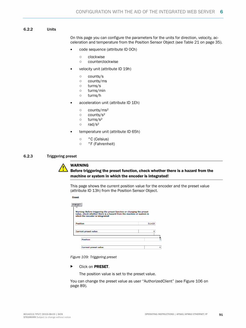
CONFIGURATION WITH THE AID OF THE INTEGRATED WEB SERVER 6
OPERATING INSTRUCTIONS | AFS60/AFM60 ETHERNET/IP 918014213/YFU7/2015-08-03 | SICK STEGMANN Subject to change without notice
6.2.2 Units
On this page you can configure the parameters for the units for direction, velocity, ac-celeration and temperature from the Position Sensor Object (see Table 21 on page 35).
� code sequence (attribute ID 0Ch)
○ clockwise○ counterclockwise
� velocity unit (attribute ID 19h)
○ counts/s○ counts/ms○ turns/s○ turns/min○ turns/h
� acceleration unit (attribute ID 1Eh)
○ counts/ms²○ counts/s²○ turns/s²○ rad/s²
� temperature unit (attribute ID 65h)
○ °C (Celsius)○ °F (Fahrenheit)
6.2.3 Triggering preset
WARNINGBefore triggering the preset function, check whether there is a hazard from themachine or system in which the encoder is integrated!
This page shows the current position value for the encoder and the preset value(attribute ID 13h) from the Position Sensor Object.
Figure 109: Triggering preset
b Click on PRESET.
The position value is set to the preset value.
You can change the preset value as user “AuthorizedClient” (see Figure 106 onpage 89).

6 CONFIGURATION WITH THE AID OF THE INTEGRATED WEB SERVER
92 OPERATING INSTRUCTIONS | AFS60/AFM60 ETHERNET/IP 8014213/YFU7/2015-08-03 | SICK STEGMANN Subject to change without notice
6.2.4 Scaling
On this page you can configure the parameters for the scaling in the Position SensorObject (see Table 21 on page 35).
� Scaling (attribute ID 0Eh)
○ on○ off
If you set the scaling to on, the following parameters are displayed:
Figure 110: Scaling
� CPR, number of steps per revolution (attribute ID 10h)� Revolutions, number of revolutions of the total resolution (This is not a Position
Sensor Object attribute.)
Only the following values can be selected: 1, 2, 4, 8, 16, 32, 64, 128, 256, 512,1,024, 2,048 and 4,096.
� The Total resolution (CMR) field indicates the value of attribute ID 11h “TotalMeasuring Range, total resolution” in the Position Sensor Object (see Table 21 onpage 35).
Figure 111: Scaling with active round axis functionality
NOTE
If the round axis functionality is activated, it is not possible to set any scaling.

CONFIGURATION WITH THE AID OF THE INTEGRATED WEB SERVER 6
OPERATING INSTRUCTIONS | AFS60/AFM60 ETHERNET/IP 938014213/YFU7/2015-08-03 | SICK STEGMANN Subject to change without notice
6.2.5 Round axis functionality
You activate the round axis functionality and configure the parameters for nominator,divisor and the total resolution (see Table 21 on page 35).
� round axis functionality (attribute ID 7Dh)
○ on○ off
If you set the round axis functionality to on, the following parameters are displayed:
Figure 112: Round axis functionality
� Nominator for the number of revolutions (attribute ID 7Eh)� Divisor for the number of revolutions (attribute ID 7Fh)� Total resolution (CMR) (attribute ID 11h)
The prerequisites and restrictions for the parameters are described in section 3.6.10on page 42.
NOTE
If you activate the round axis functionality, then on the Scaling page the scaling is setto on. However, no scaling parameters are available (see Figure 111 on page 92).
6.2.6 Changing preset value
WARNINGBefore changing the preset value, check whether there is a hazard from the ma-chine or system in which the encoder is integrated!
As soon as you have entered the value and accepted the entry using the [Enter] key,the value is applied as a position value (see Figure 109 on page 91)!
On this page you can configure the preset value in the Position Sensor Object(attribute ID 13h, see Table 21 on page 35).

6 CONFIGURATION WITH THE AID OF THE INTEGRATED WEB SERVER
94 OPERATING INSTRUCTIONS | AFS60/AFM60 ETHERNET/IP 8014213/YFU7/2015-08-03 | SICK STEGMANN Subject to change without notice
6.2.7 Limits
On this page you can configure the limits for the position, velocity, acceleration andtemperature:
� lower limit for the position (attribute ID 16h)� upper limit for the position (attribute ID 17h)
NOTE
Using the lower and upper limit for the position you can realize range monitoring. This isnot an electronic cam.
� lower limit for the velocity (attribute ID 1Bh)� upper limit for the velocity (attribute ID 1Ch)� lower limit for the acceleration (attribute ID 20h)� upper limit for the acceleration (attribute ID 21h)
If these limits are exceeded, the consequence will be the following:
� The Warning flag (attribute ID 31h) in the Position Sensor Object is set (seeTable 21 on page 35).
� On the Device page the status LED flashes (see section 6.1.1 on page 88).� The warning text is displayed on the Status page (see section 6.3.1 on page 95).
In addition other limits that are not included in the Position Sensor Object can be set:
� limit for the motion time in hours 18)
� limit for the operating time in hours 18)
� limit for the number of changes in the direction of rotation� limit for the number of clockwise starts� limit for the number of counterclockwise starts
6.2.8 Reset
On this page you can run the class service Reset and restart the encoder.
NOTE
After the restart the language will be reset to English and the user logged out.
Save parameters in the non-volatile memory
b Click on –S–.
The function uses the class service Save (service code 16h) in the Position SensorObject.
The parameters are saved in the non-volatile memory, the encoder is restarted.
18) The motion time and the operating time are always calculated from the initial commissioning of the encoder. On configuring the limit,note that encoder may already have a certain amount of motion time or operating time.

CONFIGURATION WITH THE AID OF THE INTEGRATED WEB SERVER 6
OPERATING INSTRUCTIONS | AFS60/AFM60 ETHERNET/IP 958014213/YFU7/2015-08-03 | SICK STEGMANN Subject to change without notice
Reset to the default factory settings
b Click on –D–.
The function uses the class service Reset (service code 05h) in the PositionSensor Object (data = 01h).
The parameters are reset to the factory settings, the encoder restarted.
Restart
b Click on –R–.
The encoder is restarted.
6.3 Diagnostics
On the diagnostics pages you will find detailed information on possible alarms,warnings and errors.
6.3.1 Status
The page shows a description of the error if a warning or an alarm has occurred.
Figure 113: Diagnostics status
� Current statusThe last three messages since switching on 19) are displayed.
� Status memoryThe texts for warnings, alarms and errors from the fault header are displayed (seeTable 30 on page 103). If a warning, alarm or error has not yet occurred, the textdisplayed is No entries.
� Motion time of the encoderIndicates whether the motion time is within the tolerated values (see section 6.2.7on page 94).
� Operating time of the encoderIndicates whether the operating time is within the tolerated values (see sec-tion 6.2.7 on page 94).
19) The memory is empty after switching off and on again.

6 CONFIGURATION WITH THE AID OF THE INTEGRATED WEB SERVER
96 OPERATING INSTRUCTIONS | AFS60/AFM60 ETHERNET/IP 8014213/YFU7/2015-08-03 | SICK STEGMANN Subject to change without notice
6.3.2 Velocity
This page shows the following values on the velocity from the Position Sensor Object(see Table 21 on page 35):
� velocity unit (attribute ID 19h)� current velocity (attribute ID 18h)� highest velocity that the encoder has reached since start-up (attribute ID 6Dh)� lower limit for the velocity (attribute ID 1Bh)� upper limit for the velocity (attribute ID 1Ch)
6.3.3 Temperature
This page shows the following values on the temperature from the Position SensorObject (see Table 21 on page 35):
� temperature unit (attribute ID 65h)� current temperature (attribute ID 64h)� highest operating temperature reached (attribute ID 6Fh)� lowest operating temperature reached (attribute ID 70h)� lower limit for the temperature (attribute ID 67h)� upper limit for the temperature (attribute ID 68h)
6.3.4 Time
This page shows the following values on the encoder motion time and operating timefrom the Position Sensor Object (see Table 21 on page 35):
� saved motion time in seconds (attribute ID 6Bh)� limit for the motion time in hours (see section 6.2.7 on page 94)� saved operating time in seconds (attribute ID 6Ch)� limit for the operating time in hours (see section 6.2.7 on page 94)
6.3.5 Cycles
This page shows the following values on the encoder cycles from the Position SensorObject (see Table 21 on page 35):
� number of changes in the direction of rotation (attribute ID 75h)� number of clockwise starts (attribute ID 76h)� number of counterclockwise starts (attribute ID 77h)� limit for the number of changes in the direction of rotation (see section 6.2.7 on
page 94)� limit for the number of clockwise starts (see section 6.2.7 on page 94)� limit for the number of counterclockwise starts (see section 6.2.7 on page 94)
6.3.6 Heartbeat
The AFS60/AFM60 EtherNet/IP supports Slave Sign of Life functionality (see sec-tion 3.6.3 on page 40).
Figure 114: Heartbeat

CONFIGURATION WITH THE AID OF THE INTEGRATED WEB SERVER 6
OPERATING INSTRUCTIONS | AFS60/AFM60 ETHERNET/IP 978014213/YFU7/2015-08-03 | SICK STEGMANN Subject to change without notice
If you set the heartbeat to on, the following symbols and parameters are displayed:
An LED symbol indicates the heartbeat:
O Green ActiveO Gray Not active
NOTE
As the website is refreshed every second, the change between the status cannot bedisplayed in real-time.
The Current RPI in ms column indicates the RPI.
Define the update factor in the Current update factor (2 … 127) field.
The Current update cycle in ms column indicates the heartbeat.
6.4 Tools
6.4.1 EDS
The EDS files for integrating the encoder in the PLC are saved in the encoder.
b Click Download EDS to download the files as a RAR archive.
The RAR archive contains the EDS files for the singleturn and the multiturnencoder as well as their icon.
6.4.2 Ladder routine
The configuration data are mapped between the control system and the web serverwith the aid of the ladder routine (see section 3.5.2 on page 36). The ladder routine issaved in the encoder.
You must download the appropriate ladder routine depending on whether you use theinstance 101WS and 103WS or the instance 102WS of the Assembly Object (seeTable 15 on page 23).
b Choose the ladder routine to suit the instance used. Click Download Ladder-Routine … to download the file as a RAR archive.
6.4.3 Update
You can update the firmware using FTP.
b If you are connected to the encoder using the web server, close the web browser.b Start your FTP client and enter the IP address of the encoder.b Use the following login data:
○ user name = host○ password = enc123

6 CONFIGURATION WITH THE AID OF THE INTEGRATED WEB SERVER
98 OPERATING INSTRUCTIONS | AFS60/AFM60 ETHERNET/IP 8014213/YFU7/2015-08-03 | SICK STEGMANN Subject to change without notice
Figure 115: Example for the firmware update
b Open the folder FIRMWARE_UPDATE_DRIVE.b Copy the update file (*.bin) to this folder.
The firmware update takes approx. 3 minutes.
� During the firmware update the Encoder LED initially flashes red.� Then the Encoder LED illuminates red.
After the firmware update the encoder restarts.
� The Encoder LED then illuminates green.
NOTE
Make sure that the encoder is continuously supplied with power during the firmwareupdate. If the power is interrupted the encoder will either be reset to the state prior tothe update or, in the worst case, will no longer respond.
6.4.4 Address switches
This page shows the possible settings for the address switches (see Table 27 onpage 46).
6.4.5 Fault header information
The encoder has a fault header in which the alarms and warnings that have occurredare displayed. The possible alarms and warnings are listed on the Fault header infor-mation page.

CONFIGURATION WITH THE AID OF THE INTEGRATED WEB SERVER 6
OPERATING INSTRUCTIONS | AFS60/AFM60 ETHERNET/IP 998014213/YFU7/2015-08-03 | SICK STEGMANN Subject to change without notice
6.5 Test notes
WARNINGCommissioning requires a thorough check by authorized personnel!
Before you operate a system equipped with the AFS60/AFM60 EtherNet/IP for the firsttime, make sure that the system is first checked and released by authorized personnel.Please read the notes in chapter 2 “On safety” on page 9.

7 FAULT DIAGNOSIS
100 OPERATING INSTRUCTIONS | AFS60/AFM60 ETHERNET/IP 8014213/YFU7/2015-08-03 | SICK STEGMANN Subject to change without notice
7 Fault diagnosis
This chapter describes how to identify and rectify errors and malfunctions of theAFS60/AFM60 EtherNet/IP Absolute Encoder.
7.1 In the event of faults or errors
WARNINGCease operation if the cause of the malfunction has not been clearly identified!
Stop the machine if you cannot clearly identify or allocate the error and if you cannotsafely rectify the malfunction.
7.2 SICK STEGMANN support
If you cannot remedy an error with the help of the information provided in this chapter,please contact your local SICK STEGMANN representative.
7.3 Diagnostics
7.3.1 Error and status indications on the LEDs
Figure 116: Position of the LEDs
Link 1
Encoder
Link 2Mod
Net
Screw cover

FAULT DIAGNOSIS 7
OPERATING INSTRUCTIONS | AFS60/AFM60 ETHERNET/IP 1018014213/YFU7/2015-08-03 | SICK STEGMANN Subject to change without notice
Status LEDs Mod, Net and Encoder
LED Mod shows the device status, LED Net shows the status of the CIP connection andLED Encoder shows the status of the internal measuring device in theAFS60/AFM60 EtherNet/IP.
Display Description
LED Mod
o Off No operating voltage
O Green Device in operation
Ö Green Stand-by/device not configured, no IP address assigned
Ö Red Warning, but device still operationalorFirmware update in progress
O Red Error, device not operational
Ö Red/green Self-test at power-on
LED Net
o Off No operating voltageorNo IP address
Ö Green No connectionThe device has an IP address but no CIP connection.
O Green The device has an IP address and a CIP connection.
Ö Red Warning, connection timeoutCleared by reset or a new connection
O Red ErrorIP address has been assigned to another device already.
Ö Red/green Self-test at power-on
LED Encoder
o Off No operating voltageorNo IP address
Ö Green WarningIncorrect parameter
O Green Device in operation
Ö Red Warning, but device still operationalorFirmware update in progress
O Red ErrorEncoder errororReboot after firmware update in progress
Ö Red/green Self-test at power-on
Table 28: Meaning of the status LEDs Mod, Net and Encoder

7 FAULT DIAGNOSIS
102 OPERATING INSTRUCTIONS | AFS60/AFM60 ETHERNET/IP 8014213/YFU7/2015-08-03 | SICK STEGMANN Subject to change without notice
Ethernet Link LEDs Link 1 and 2
The Ethernet Link LEDs Link 1 and Link 2 display the status of the physical connectionon the Ethernet interface.
Display Description
o Off No operating voltage
or
No Ethernet connection
O Green Ethernet connection established
O Yellow Interface port locked
Ö Green Data transmission TxD/RxD
Ö Yellow Data collisions
Table 29: Meaning of the LEDs Link 1 and Link 2
7.3.2 Self-test via EtherNet/IP
To check the sensors and the most important functions of the encoder, a self-test isavailable.
NOTE
The self-test is only allowed to be undertaken with the encoder at standstill.
The self-test can be triggered via the diagnostics bit of attribute ID 0Dh in the PositionSensor Object (see Table 21 on page 35). If an error occurs, bit 27 in the fault headeris set (see Table 30 on page 103).
After the self-test the diagnostic bit of attribute 13 is automatically reset to 0.
7.3.3 Warnings, alarms and errors via EtherNet/IP
Within EtherNet/IP warnings, alarms and errors can be retrieved using implicit mes-sages and also explicit messages.
If connections are established via the I/O assembly, the fault header can be read usingthe instances 101, 102 and 103 as well as the instances 101WS, 102WS and 103WS(see Table 16 on page 25).
Alarms and warnings for the encoder can be read via the Position Sensor Object (seeTable 21 on page 35) with the aid of the attributes.
For errors, alarms and warnings the following applies:Bit status = 0: no error, alarm or warningBit status = 1: error, alarm or warning present
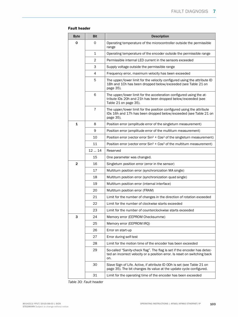
FAULT DIAGNOSIS 7
OPERATING INSTRUCTIONS | AFS60/AFM60 ETHERNET/IP 1038014213/YFU7/2015-08-03 | SICK STEGMANN Subject to change without notice
Fault header
Byte Bit Description
0 Operating temperature of the microcontroller outside the permissiblerange
1 Operating temperature of the encoder outside the permissible range
2 Permissible internal LED current in the sensors exceeded
3 Supply voltage outside the permissible range
4 Frequency error, maximum velocity has been exceeded
5 The upper/lower limit for the velocity configured using the attribute ID1Bh and 1Ch has been dropped below/exceeded (see Table 21 onpage 35).
6 The upper/lower limit for the acceleration configured using the at-tribute IDs 20h and 21h has been dropped below/exceeded (seeTable 21 on page 35).
0
7 The upper/lower limit for the position configured using the attributeIDs 16h and 17h has been dropped below/exceeded (see Table 21 onpage 35).
8 Position error (amplitude error of the singleturn measurement)
9 Position error (amplitude error of the multiturn measurement)
10 Position error (vector error Sin² + Cos² of the singleturn measurement)
11 Position error (vector error Sin² + Cos² of the multiturn measurement)
12 … 14 Reserved
1
15 One parameter was changed.
16 Singleturn position error (error in the sensor)
17 Multiturn position error (synchronization MA single)
18 Multiturn position error (synchronization quad single)
19 Multiturn position error (internal interface)
20 Multiturn position error (FRAM)
21 Limit for the number of changes in the direction of rotation exceeded
22 Limit for the number of clockwise starts exceeded
2
23 Limit for the number of counterclockwise starts exceeded
24 Memory error (EEPROM Checksumme)
25 Memory error (EEPROM IRQ)
26 Error on start-up
27 Error during self-test
28 Limit for the motion time of the encoder has been exceeded
29 So-called “Sanity-check flag”. The flag is set if the encoder has detec-ted an incorrect velocity or a position error. Is reset on switching backon.
30 Slave Sign of Life. Active, if attribute ID 0Dh is set (see Table 21 onpage 35). The bit changes its value at the update cycle configured.
3
31 Limit for the operating time of the encoder has been exceeded
Table 30: Fault header

7 FAULT DIAGNOSIS
104 OPERATING INSTRUCTIONS | AFS60/AFM60 ETHERNET/IP 8014213/YFU7/2015-08-03 | SICK STEGMANN Subject to change without notice
Alarms
If, for example, the internal self-test detects that the position value has been incorrectlycalculated or an incorrect configuration value has been transferred to the encoder, thealarm flag is set, (attribute 46, see Table 21 on page 35).
WARNINGIt is imperative to evaluate the alarms in your application!
In case of a serious error, incorrect position values may be output. This change couldcause an unexpected movement that may result in a hazard for persons or damage tothe system or other items.
In addition the Mod LED illuminates red continuously.
The alarm type is coded in a bit field of attributes 44 and 45.
Bit Description
0 Position error
1 Error during self-test
2 … 11 Reserved
12 Incorrect checksum (vendor specific)
4 Error on system start-up (vendor specific)
14 … 15 Reserved
Table 31: Alarms
Warnings
If, for example, the velocity or temperature drop below/exceed the limit values, thewarning flag is set (attribute ID 31h, see Table 21 on page 35).
In addition the Mod LED flashes red.
The warning type is coded in a bit field of attribute IDs 2Fh and 30h.
NOTE
The position value will continue to be correctly calculated, the encoder is therefore stillready for operation.
O Red
Ö Red

FAULT DIAGNOSIS 7
OPERATING INSTRUCTIONS | AFS60/AFM60 ETHERNET/IP 1058014213/YFU7/2015-08-03 | SICK STEGMANN Subject to change without notice
Bit Description
0 Maximum velocity exceeded
1 Permissible internal LED current in the sensors exceeded
2 … 5 Not supported
6 The lower limit for the velocity configured with attribute 1Bh has been droppedbelow.
7 The upper limit for the velocity configured with attribute 1Ch has been exceeded.
8 The lower limit for the acceleration configured with attribute 20h has beendropped below.
9 The upper limit for the acceleration configured with attribute 21h has beenexceeded.
10 The lower/upper limit for the position configured with attribute 16h and 17h hasbeen dropped below/exceeded.
11 … 12 Reserved
13 20) The lower/upper limit for the temperature configured with attribute 67h and 68hhas been dropped below/exceeded.
14 20) The operating voltage has dropped below/exceeded the minimum/maximumoperating voltage.
Table 32: Warnings
7.3.4 Error messages from the Allen-Bradley control system
If the encoder is integrated into an Allen-Bradley control system, some error messagesmay occur that have message text from which the cause is not immediately obvious.
Figure 117: Example of an error message in RSLogix
20) Vendor specific warning.

7 FAULT DIAGNOSIS
106 OPERATING INSTRUCTIONS | AFS60/AFM60 ETHERNET/IP 8014213/YFU7/2015-08-03 | SICK STEGMANN Subject to change without notice
The following error messages stem from the RSLogix 5000 software.
Error code Message Possible cause
16#0108 Connection RequestError Connection Type(Multicast/Unicast)not supported.
b Check whether the configuration assembly (in-stance 100 of the Assembly Object) is activated.If yes, check whether the configuration data arecorrectly and fully configured in this assembly(see Figure 31 on page 55).
16#0114 Electronic KeyingMismatched: Electro-nic keying productcode and/or vendorID mismatched.
b Check whether the wrong EDS file has been se-lected (e.g. singleturn instead of multiturn or viceversa, see section 5.5 on page 56).
16#0127 Connection RequestError: Invalid outputsize.
b Check whether the correct communication formatfor the control system is used. The default valuein the control system is “Data-DINT”. The encoderrequires the communication format: “Input Data-DINT”.
16#0204 Connection RequestError: Connectiontimed out.
b Check the supply voltage on the encoder.b Check the Ethernet cables for the encoder for
open circuit.b Check whether the IP address of the encoder
matches the IP address saved in the controlsystem. Possible causes:
○ The address switches are not engagedcorrectly (see Figure 18 on page 46).
○ The encoder has lost the IP addressassigned to it after switching back on(see section 5.2.3 on page 50).
Table 33: Error messages from the RSLogix 5000 software

ANNEX 8
OPERATING INSTRUCTIONS | AFS60/AFM60 ETHERNET/IP 1078014213/YFU7/2015-08-03 | SICK STEGMANN Subject to change without notice
8 Annex
8.1 EU declaration of conformity
Figure 118: EU declaration of conformity
NOTE
You can obtain the complete EU declaration of conformity via the SICK homepage onthe Internet at: www.sick.com

9 LIST OF FIGURES
108 OPERATING INSTRUCTIONS | AFS60/AFM60 ETHERNET/IP 8014213/YFU7/2015-08-03 | SICK STEGMANN Subject to change without notice
9 List of figures
Figure 1: Setting a preset value ........................................................................ 12
Figure 2: Example position measurement on a rotary table withtransmission ratio .............................................................................. 13
Figure 3: Example position measurement on a rotary table withouttransmission ratio .............................................................................. 14
Figure 4: Example of an EtherNet/IP network in a star topology....................... 14
Figure 5: Example of an EtherNet/IP network in a Device Level Ring ............... 15
Figure 6: CIP and other services........................................................................ 16
Figure 7: Ethernet FRAME ................................................................................. 16
Figure 8: Ethernet data field.............................................................................. 17
Figure 9: Supported classes.............................................................................. 18
Figure 10: Connections for the Identity Object .................................................... 19
Figure 11: Connections for the I/O assembly ...................................................... 24
Figure 12: Connections for the configuration assembly ...................................... 26
Figure 13: Connections for explicit messages to the Position Sensor Object...... 28
Figure 14: Configuration memory........................................................................ 38
Figure 15: Position of the LEDs, the address switches and the presetpushbutton......................................................................................... 43
Figure 16: Position of the connections of the AFS60/AFM60 EtherNet/IP ......... 44
Figure 17: Connections of the AFS60/AFM60 EtherNet/IP................................. 44
Figure 18: Address switch an preset pushbutton................................................ 46
Figure 19: MAC address in the BOOTP/DHCP server .......................................... 49
Figure 20: Entry of the IP address in the BOOTP/DHCP server ........................... 49
Figure 21: Integration of the IP address in the BOOTP/DHCP server .................. 49
Figure 22: RSWho button in RSLinx Classic ........................................................ 50
Figure 23: Encoder on the path AB_ETHIP-1 in RSLinx Classic ........................... 50
Figure 24: Configuring the hardware................................................................... 51
Figure 25: Adding communication interface........................................................ 51
Figure 26: Selecting communication interface.................................................... 52
Figure 27: Name of the communication interface............................................... 52
Figure 28: Integrating encoder ............................................................................ 53
Figure 29: Selecting module................................................................................ 53
Figure 30: Entering module properties................................................................ 54
Figure 31: Example data for a configuration assembly ....................................... 55
Figure 32: Loading configuration......................................................................... 55
Figure 33: Communication status ....................................................................... 55
Figure 34: Checking the communication............................................................. 56
Figure 35: Integrating encoder using EDS........................................................... 56

LIST OF FIGURES 9
OPERATING INSTRUCTIONS | AFS60/AFM60 ETHERNET/IP 1098014213/YFU7/2015-08-03 | SICK STEGMANN Subject to change without notice
Figure 36: Selecting module................................................................................ 57
Figure 37: Entering module properties................................................................ 57
Figure 38: Changing connections........................................................................ 58
Figure 39: Changing data format......................................................................... 58
Figure 40: Checking the communication............................................................. 58
Figure 41: Configuration of the encoder.............................................................. 59
Figure 42: Selection of language (in the example 103WS) ................................. 59
Figure 43: Correctly configured project with two encoder modules..................... 60
Figure 44: Selection of the Import Routine... command...................................... 61
Figure 45: Dialog Import Configuration ............................................................... 62
Figure 46: Selection of the encoder .................................................................... 63
Figure 47: Selection of operation for the component.......................................... 63
Figure 48: Selection of the tags for the instance used........................................ 64
Figure 49: Selection of the operation for the tag references............................... 64
Figure 50: Changing the tag names .................................................................... 65
Figure 51: Project structure after the import....................................................... 65
Figure 52: MainRoutine without SubRoutine....................................................... 66
Figure 53: MainRoutine with SubRoutine............................................................ 66
Figure 54: Imported SickAFx ladder routine in the online mode ......................... 67
Figure 55: Initializing and starting the SubRoutine ............................................. 67
Figure 56: Reading the parameters in GetData................................................... 68
Figure 57: Example for changing data in the web server and reading theparameters in the control system....................................................... 69
Figure 58: Changing parameters in SetData ....................................................... 69
Figure 59: Example for changing data in the control system and reading inthe web server.................................................................................... 70
Figure 60: Function block in the Rockwell control system................................... 71
Figure 61: Control system in the offline mode..................................................... 71
Figure 62: Adding a new variable ........................................................................ 72
Figure 63: Definition of the variable TEMP_Trigger ............................................. 72
Figure 64: Definition of the variable TEMP_OneShot .......................................... 73
Figure 65: Definition of the variable TEMP_Value ............................................... 73
Figure 66: Definition of the variable TEMP_Message.......................................... 74
Figure 67: Variable structure for reading the temperature.................................. 74
Figure 68: Opening MainRoutine......................................................................... 74
Figure 69: Adding ExamineOn block.................................................................... 75
Figure 70: Allocation of the variable TEMP_Trigger to ExamineOn...................... 75
Figure 71: Adding ONS block............................................................................... 75
Figure 72: Allocation of the variable TEMP_OneShot to ONS.............................. 76

9 LIST OF FIGURES
110 OPERATING INSTRUCTIONS | AFS60/AFM60 ETHERNET/IP 8014213/YFU7/2015-08-03 | SICK STEGMANN Subject to change without notice
Figure 73: Adding MSG block .............................................................................. 76
Figure 74: Allocation of the variable TEMP_Message to MSG............................. 76
Figure 75: Opening configuration dialog box for the MSG block ......................... 77
Figure 76: Configuration dialog box for the MSG block ....................................... 77
Figure 77: Communication tab............................................................................ 77
Figure 78: Selecting encoder............................................................................... 78
Figure 79: Selected encoder ............................................................................... 78
Figure 80: Transferring the program to the control system................................. 78
Figure 81: Display of the temperature value in TEMP_Value .............................. 78
Figure 82: Adding a new variable ........................................................................ 79
Figure 83: Definition of the variable PRESET_Trigger.......................................... 79
Figure 84: Definition of the variable PRESET_OneShot....................................... 80
Figure 85: Definition of the variable PRESET_Value............................................ 80
Figure 86: Definition of the variable PRESET_Message ...................................... 81
Figure 87: Variable structure for setting a preset value ...................................... 81
Figure 88: Opening MainRoutine......................................................................... 81
Figure 89: Adding Rung block.............................................................................. 82
Figure 90: Adding ExamineOn block.................................................................... 82
Figure 91: Allocation of the variable PRESET_Trigger to ExamineOn .................. 82
Figure 92: Adding ONS block............................................................................... 83
Figure 93: Allocation of the variable PRESET_OneShot to ONS........................... 83
Figure 94: Adding MSG block .............................................................................. 83
Figure 95: Allocation of the variable PRESET_Message to MSG ......................... 84
Figure 96: Opening configuration dialog box for the MSG block ......................... 84
Figure 97: Configuration dialog box for the MSG block ....................................... 84
Figure 98: Communication tab............................................................................ 85
Figure 99: Selecting encoder............................................................................... 85
Figure 100: Selected encoder ............................................................................... 85
Figure 101: Transferring the program to the control system................................. 86
Figure 102: Display of the preset value in PRESET_Value..................................... 86
Figure 103: Web server user interface .................................................................. 87
Figure 104: Selection of language......................................................................... 87
Figure 105: LED symbol......................................................................................... 88
Figure 106: Log on................................................................................................. 89
Figure 107: Changing the password...................................................................... 90
Figure 108: Changing the password...................................................................... 90
Figure 109: Triggering preset................................................................................. 91
Figure 110: Scaling................................................................................................ 92
Figure 111: Scaling with active round axis functionality........................................ 92

LIST OF FIGURES 9
OPERATING INSTRUCTIONS | AFS60/AFM60 ETHERNET/IP 1118014213/YFU7/2015-08-03 | SICK STEGMANN Subject to change without notice
Figure 112: Round axis functionality ..................................................................... 93
Figure 113: Diagnostics status.............................................................................. 95
Figure 114: Heartbeat ........................................................................................... 96
Figure 115: Example for the firmware update....................................................... 98
Figure 116: Position of the LEDs .........................................................................100
Figure 117: Example of an error message in RSLogix .........................................105
Figure 118: EU declaration of conformity ............................................................107

10 LIST OF TABLES
112 OPERATING INSTRUCTIONS | AFS60/AFM60 ETHERNET/IP 8014213/YFU7/2015-08-03 | SICK STEGMANN Subject to change without notice
10 List of tables
Table 1: Authorised personnel ........................................................................... 9
Table 2: Disposal of the assemblies ................................................................ 10
Table 3: Special features of the encoder variants ........................................... 11
Table 4: Example CIP object model.................................................................. 17
Table 5: Supported classes.............................................................................. 19
Table 6: Class services of the Identity Object................................................... 19
Table 7: Class attributes of the Identity Object ................................................ 20
Table 8: Instance Services of the Identity Object ............................................. 20
Table 9: Instance attributes of the Identity Object ........................................... 21
Table 10: Bits of the instance attribute “Status”................................................ 21
Table 11: Bits 4 to 7 of the instance attribute “Status” ..................................... 22
Table 12: Class services of the Assembly Object ............................................... 22
Table 13: Class attributes of the Assembly Object............................................. 22
Table 14: Instance Services of the Assembly Object.......................................... 23
Table 15: Instance attributes of the Assembly Object........................................ 23
Table 16: Data format of the attributes of the I/O assembly ............................. 25
Table 17: Data format for the attributes for the configuration assembly........... 27
Table 18: Class services of the Position Sensor Object...................................... 28
Table 19: Class attributes of the Position Sensor Object ................................... 29
Table 20: Instance services of the Position Sensor Object ................................ 29
Table 21: Instance attributes of the Position Sensor Object .............................. 35
Table 22: Configuration memory — functions of the different types ofmemory .............................................................................................. 37
Table 23: Parameters that are saved or reset.................................................... 39
Table 24: Examples for total resolution.............................................................. 41
Table 25: Pin assignment for the connection of the voltage supply................... 45
Table 26: Pin assignment for the Ethernet port 1 and 2 connections................ 45
Table 27: Address switches — Meaning of the values that can be set............... 46
Table 28: Meaning of the status LEDs Mod, Net and Encoder.........................101
Table 29: Meaning of the LEDs Link 1 and Link 2............................................102
Table 30: Fault header.....................................................................................103
Table 31: Alarms ..............................................................................................104
Table 32: Warnings ..........................................................................................105
Table 33: Error messages from the RSLogix 5000 software............................106

OPERATING INSTRUCTIONS | AFS60/AFM60 ETHERNET/IP 1138014213/YFU7/2015-08-03 | SICK STEGMANN Subject to change without notice

114 OPERATING INSTRUCTIONS | AFS60/AFM60 ETHERNET/IP 8014213/YFU7/2015-08-03 | SICK STEGMANN Subject to change without notice

OPERATING INSTRUCTIONS | AFS60/AFM60 ETHERNET/IP 1158014213/YFU7/2015-08-03 | SICK STEGMANN Subject to change without notice

SICK AG | Waldkirch | Germany | www.sick.com
8014
213/YFU7
/201
5-08
-03/
en ∙
REIP
A/XX
(201
5-08
) ∙ U
Smod
4c
int4
4
More representatives and agencies at www.sick.com
AustraliaPhone +61 3 9457 0600
1800 334 802 – tollfreeE-Mail [email protected]
AustriaPhone +43 (0)22 36 62 28 8-0E-Mail [email protected]
Belgium/LuxembourgPhone +32 (0)2 466 55 66E-Mail [email protected]
BrazilPhone +55 11 3215-4900E-Mail [email protected]
CanadaPhone +1 905 771 14 44E-Mail [email protected]
Czech RepublicPhone +420 2 57 91 18 50E-Mail [email protected]
ChilePhone +56 2 2274 7430E-Mail [email protected]
ChinaPhone +86 4000 121 000E-Mail [email protected]
DenmarkPhone +45 45 82 64 00E-Mail [email protected]
FinlandPhone +358-9-2515 800E-Mail [email protected]
FrancePhone +33 1 64 62 35 00E-Mail [email protected]
GemanyPhone +49 211 5301-301E-Mail [email protected]
Great BritainPhone +44 (0)1727 831121E-Mail [email protected]
Hong KongPhone +852 2153 6300E-Mail [email protected]
HungaryPhone +36 1 371 2680E-Mail [email protected]
IndiaPhone +91–22–4033 8333E-Mail [email protected]
IsraelPhone +972-4-6881000E-Mail [email protected]
ItalyPhone +39 02 27 43 41E-Mail [email protected]
JapanPhone +81 (0)3 5309 2112E-Mail [email protected]
MalaysiaPhone +603 808070425E-Mail [email protected]
NetherlandsPhone +31 (0)30 229 25 44E-Mail [email protected]
New Zealand Phone +64 9 415 0459
0800 222 278 – tollfreeE-Mail [email protected]
Norway Phone +47 67 81 50 00E-Mail [email protected]
PolandPhone +48 22 837 40 50E-Mail [email protected]
RomaniaPhone +40 356 171 120 E-Mail [email protected]
RussiaPhone +7-495-775-05-30E-Mail [email protected]
SingaporePhone +65 6744 3732E-Mail [email protected]
SlovakiaPhone +421 482 901201E-Mail [email protected]
SloveniaPhone +386 (0)1-47 69 990E-Mail [email protected]
South AfricaPhone +27 11 472 3733E-Mail [email protected]
South KoreaPhone +82 2 786 6321E-Mail [email protected]
SpainPhone +34 93 480 31 00E-Mail [email protected]
SwedenPhone +46 10 110 10 00E-Mail [email protected]
SwitzerlandPhone +41 41 619 29 39E-Mail [email protected]
TaiwanPhone +886 2 2375-6288E-Mail [email protected]
ThailandPhone +66 2645 0009E-Mail [email protected]
TurkeyPhone +90 (216) 528 50 00E-Mail [email protected]
United Arab EmiratesPhone +971 (0) 4 88 65 878E-Mail [email protected]
USA/MexicoPhone +1(952) 941-6780
1 (800) 325-7425 – tollfreeE-Mail [email protected]
VietnamPhone +84 8 62920204E-Mail [email protected]


![[PPT]Fast Ethernet and Gigabit Ethernet - WPIweb.cs.wpi.edu/~rek/Undergrad_Nets/B04/Fast_Ethernet.ppt · Web viewFast Ethernet and Gigabit Ethernet Fast Ethernet (100BASE-T) How to](https://static.documents.pub/doc/80x56/5b29d4a97f8b9aad2f8b4e9d/pptfast-ethernet-and-gigabit-ethernet-rekundergradnetsb04fastethernetppt.jpg)

