The information provided in this overview contains descriptions or characteristics of performance which in case of actual use do not always apply as described or which may change as a result of further development of the products. An obligation to provide the respective characteristics shall only exist if expressly agreed in the terms of contract. Availability and technical specifications are subject to change without notice.All product designations may be trademarks or product names of Siemens AG or supplier companies whose use by third parties for their own purposes could violate the rights of the owners.
S i e m e n s P r o d u c t O v e r v i e w S I P L U S
SIPLUS extreme
Automation Systems Operator Control and Monitoring Systems Industrial Communication Industrial Controls Power Supply Drive Technology
SIPLUS LOGO! SIPLUS S7-200 SIPLUS S7-1200 SIPLUS S7-300 SIPLUS S7-300F SIPLUS S7-400/400H SIPLUS PCS7 Bundle SIPLUS ET 200M SIPLUS ET 200M F SIPLUS ET 200S SIPLUS ET 200S F SIPLUS Micro Panels SIPLUS Touch Panels SIPLUS Operator Panels SIPLUS Multi Panels SIPLUS Basic Panels SIPLUS Communica-
tions Processors SIPLUS NET SIPLUS SINAUT SIPLUS AS-Interface SIPLUS SIMOCODE SIPLUS power SIPLUS smart SIPLUS modular SIPLUS UPS SIPLUS upmiter POSMO A Positioning Motors
Catalog ST 70 / IC 10 ST 70 ST 70 ST 70 ST 70 ST 70 ST PCS 7 ST 70 ST 70 ST 70 ST 70 ST 80 / ST PC ST 80 / ST PC ST 80 / ST PC ST 80 / ST PC ST 80 / ST PC IK PI IK PI IK PI IC 10 – KT 10.1 KT 10.1 KT 10.1 KT 10.1 IC 10 –
Brief description Modular logic mod-ules for control tasks in the lower perfor-mance range;detached text display
Compact micro PLCs with maximum perfor-mance capability
Modular, compact controllers for discrete and stand-alone auto-mation solutions
Modular controllers for the low to mid-performance ranges
Modular controllers for the low to mid-per-formance ranges for failsafe applications
Modular high-per-formance controllers for the mid to upper performance ranges
Flexible, scalable au-tomation system with different safety and availability levels
Modular I/O system, especially for user-specifi c and complex automation tasks
Modular I/O system, especially for user-specifi c and complex automation tasks, in safety-related design
Multifunctional andhighly modular I/O sys-tem with IP20 degree of protection
Multifunctional andhighly modular I/O system with IP20 degree of protection in safety-related design
User-friendlytext displays for S7-200 for displaying message texts, inter-ventions in the control program, or setting inputs and outputs
Touch Panels with comprehensive func-tions for operator control and monitor-ing of machines and plants with analog touch screens
Touch/Key Panel for operator control and monitoring of machines and plants with touch screen and additional system and function keys
Touch Panels for visualizing multiple automation tasks on a single platform; avail-able with touch screen or membrane keypad
Low-cost operator panels with basic HMI functionality for simple applications
Communication mod-ules for all SIMATIC formats for reliev-ing the controller of communication tasks, with Profi bus/Profi net interfaces
Passive network com-ponents:electrical outlets; SCALANCE X:Industrial Ethernet switches and Indus-trial Ethernet media converters
SIPLUS MD2 dedicated line modem;GSM/GPRS modem;EGPRS router;TIM communication modules
AS-Interface analog modules for record-ing and transmitting local analog signals. Connection to the higher-level controller via an AS-Interface master in accordance with Specifi cation 2.1 or Specifi cation 3.0
Flexible motor man-agement system for constant-speed mo-tors in the low-voltage range
Power supply for automation solutions in the lower perfor-mance range; with wide-range input for 48-220 V DC; small, compact design
Powerful standard power supply, com-pact design and high overload capability
Technology power supply for demanding solutions, compact metal enclosure, wide-range input, high effi ciency, high overload capability
DC UPS with recharge-able lead-gelbattery,battery management for long service life of battery
SIPLUS upmiter upstream device between the battery and power supply terminals; ensuresreliable operation onthe battery of internal-combustion engines
Intelligent positioning motor as distributed participant on Profi bus DP
Pollutant concentration in accordance with EN 60721-3-3
Suitable for industrial atmospheres in accordance with EN 60721-3-3 Class 3C4 for chemically active substances such as SO2, H2S, Cl, HCl, incl. salt mist, EN 60721-3-3 Class 3B2 for biologically active substances such as mold and fungal spores, and EN 60721-3-3 Class 3S4 for mechanically active substances, including sand and dust
Class 3B2, 3C4, 3S4 Class 3B2, 3C4, 3S4 Class 3B2, 3C4, 3S4 Class 3B2, 3C4, 3S4 Class 3B2, 3C4, 3S4 Class 3B2, 3C4, 3S4 Class 3B2, 3C4, 3S4 Class 3B2, 3C4, 3S4 Class 3B2, 3C4, 3S4 Class 3B2, 3C4, 3S4 Class 3B2, 3C4, 3S4 Class 3B2, 3C4, 3S4 Class 3B2, 3C4, 3S4 Class 3B2, 3C4, 3S4 Class 3B2, 3C4, 3S4 Class 3B2, 3C4, 3S4 Class 3B2, 3C4, 3S4 Class 3B2, 3C4, 3S4 Class 3B2, 3C4, 3S4 Available soon Available soon Class 3B2, 3C4, 3S4 Class 3B2, 3C4, 3S4 Class 3B2, 3C4, 3S4 Class 3B2, 3C4, 3S4 – –
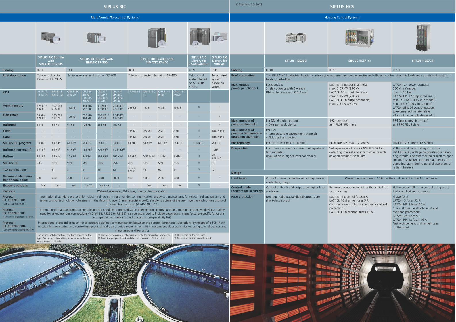
International standard protocol for telecontrol; permits multi-vendor communication of devices and systems for telecontrol equipment and station control technology; robustness in the data link layer (hamming distance 4), simple structure of the user layer; asynchronous protocol
for serial transmission (V.24/V.28, V.11)
Protocol IEC 60870-5-103(connection of protection devices)
International standard protocol for telecontrol; regulates communication between one central unit and multiple protective devices; mainly used for asynchronous connections (V.24/V.28, RS232 or RS485); can be expanded to include proprietary, manufacturer-specifi c functions
(compatibility is only ensured through interoperability list)
International standard protocol for telecontrol; defi nes communication between the control center and substations by means of a TCP/IP con-nection for monitoring and controlling geographically distributed systems; permits simultaneous data transmission using several devices and
simultaneous diagnostics
The actually valid operating conditions depend on the type. For further information, please refer to the cor-responding data sheets.
1) The memory requirements increase due to the amount of information2) Free storage space is reduced due to the amount of information
3) Dependent on the CPU used4) Dependent on the controller used
SIPLUS HCS
Heating Control Systems
SIPLUS HCS300I SIPLUS HCS716I SIPLUS HCS724I
Catalog IC 10 IC 10 IC 10
Brief description The SIPLUS HCS industrial heating control systems permit extremely precise and effi cient control of ohmic loads such as infrared heaters or heating cartridges.
Max. output power per channel
Basic device:3 relay outputs with 5 A eachDM: 6 channels with 0.5 A each
LA724I: 24 power outputs;230 V in Y mode;max. 1.15 kWLA724I HP: 12 output channels;max. 2.3 kW (230 V in Y mode);max. 4 kW (400 V in Δ mode)LA724I SSR: 24 control outputsto external solid-state relays24 inputs for simple diagnostics
Max. number of possible channels
Per DM: 6 digital outputs4 DMs per basic device
192 (per rack)as 1 PROFIBUS slave
384 (per central interface)as 1 PROFIBUS slave
Max. number of possible temperature detection channels
Per TM:4 temperature measurement channels4 TMs per basic device
Diagnostics Possible via current or current/voltage detec-tion modules(evaluation in higher-level controller)
Voltage diagnostics via PROFIBUS DP for detecting internal and external faults such as open circuit, fuse failure
Voltage and current diagnostics via PROFIBUS DP; voltage diagnostics for detec-ting internal and external faults such as open circuit, fuse failure; current diagnostics for detecting faults during parallel operation of radiant heaters
Design
Load types Control of semiconductor switching devices, contactors, relays
Ohmic loads with max. 15 times the cold current in the 1st half-wave
Control mode(percentage accuracy)
Control of the digital outputs by higher-level controller
Full-wave control using triacs that switch at zero crossing
Half-wave or full-wave control using triacs that switch at zero crossing
Fuse protection Not required because digital outputs are short-circuit proof
LA716: 16 channel fuses 5 ALA716I: 16 channel fuses 5 AChannel fuses as short-circuit and overload protection:LA716I HP: 8 channel fuses 10 A
Phase fuses:LA724I: 3 fuses 32 ALA724I HP: 3 fuses 40 AChannel fuses as short-circuit andoverload protection:LA724I: 24 fuses 5 ALA724I HP: 12 fuses 16 AFast replacement of channel fuseson the front
SIPLUS CMS
Condition Monitoring Systems
SIPLUS CMS1000 SIPLUS CMS2000 SIPLUS CMS4000
Catalog – – –
Brief description The SIPLUS CMS Condition Monitoring Systems are used for monitoring mechanical components permanently. This facilitates predictive maintenance so that maintenance operations can be planned and implemented in due time.
Monitoring of Motors, generators, fans, pumps, etc. for imbalance, misalignment, roller bearings, etc.
Analysis procedures
Characteristic values Bearing monitoring: DKW, based on K(t) according to VDI 3832, vibration monitoring: RMS based on DIN ISO10816-3
– – CREST factor, etc. Application-specific characteristic values
– – Orbit analysis, free configuration of further analysis procedures
Monitoring function
Adjustable limit values for DKW and RMS: Warning, alarm
– Adjustable alarm ranges for frequency spectrums
– Limit monitoring of analog inputs
– Temperature monitoring
– – Creation of own monitoring algorithms
Recording function
– Raw data logging: Manually or event-triggered,snapshot of the FFT, characteristic values, long-term trend recording
– – Black box for process data
Visualization
Traffic light status display via binary outputs SIPLUS CMS X-Tools software
Local display Via Firefox® web browser (registered trademark of Mozilla)
Max. number and type of connectable sensors
1 MEMS sensor1 speed sensor
2 IEPE vibration sensors, 1 speed sensor (digital)6 temperature sensors
180 sensors, IEPE or analog
Measuring inputs Basic device IFN VIB-ACC IFN analog input
Frequency range 1 Hz to 6.5 kHz 10 Hz to 10 kHz 0.1 Hz to 40 kHz 0 Hz to 40 kHz
Scanning frequency, max.
20 kHz 46 kHz 195 kHz 195 kHz
SIPLUS ECC
Electrical Charging Components
SIPLUS ECC1000
CM-100
SIPLUS ECC2000
CM-230standalone
CM-230managed
Catalog IC 10 IC 10
Brief description With SIPLUS ECC, the charging controllers for the charg-ing infrastructure, permit standard-compliant and reliable charging of electric vehicles. No matter whether you are thinking of a simple solution for private use or a professional charging station. A charging controller that communicates with the electric vehicle and controls and monitors the corresponding switching devices is always required as the central charging component.
Field of application(IE C 61851)
Charging solution for standalone operation
Communication-capable charging solution for stand-alone operation
No Dynamic specifi cation of charging cur-rent during operation
Integrated sensors No Temperature and humidity monitoring in the charging station
Service and diagnos-tics
Diagnostics via LED
Diagnostics via LED, web interface for diagnostics and parameter assignment
Supply voltage 24 V DC or 110/230 V AC
24 V DC
Charging current 13, 16, 20, 32 A; 13/32 A switchable
Can be set between 6 A ... 80 A over Ethernet
Standards IEC/EN 61851-1 Part 1 and Part 22 (conductive charging systems for electric vehicles), charging mode 3,
CE accor ding to IEC 61010, C-Tick
Public charging with 2 charging points, implemented with
CM-230 (managed) charging controller
1/3AC
SCALANCE X Ethernet Switch
1/3AC
SIRIUSPowerContactor
SIRIUSCircuit Breaker
RCD
Cha
rgin
g O
utpu
t 1
Cha
rgin
g O
utpu
t 2
Ethernet
SIPLUS ECC2000
CM-230
SIPLUS ECC2000 CM-230
SIPLUS HMI KTP 600
SIMATIC S7
SIDOOR
Door Management System
SIDOOR AT12 SIDOOR AT40
Catalog – –
Brief description SIDOOR permits easy, quick and ver-satile operation as well as installation and parameterization of, for example, elevator door systems (sliding door and revolving door systems).
• 230 V AC +/- 15% input voltage• Operating temperature -20 °C to +55 °C• Vandalism-proof• Supports energy-optimized opera-
tion of the cabin
120 kg max. door weightIntegrated switch-mode power sup-ply, therefore:• Less installation effort• Less cabling required• Single-button operation for com-
plete commissioning
400 kg door weightFlexible motor management permits power adjustment using 3 motor typesSingle-button operation for complete commissioningApplication-optimized power supply facilitates 80% weight reduction
Motor systemDC Motor Gear unit / sensor
120 kg 120 kg 180 kg 400 kg
Controller16-bit µPCFlash memory4Q (H bridge)Power unit
Power supply1) Toroidal-core transform-
er incl. rectifi er fi lter2) Optimized compact
switch-mode power supply
Inputs 3 4
1x open1x closed
1x revers.1x light barrier
Outputs 2(open/close)
3(open/close/reverse.)
Interfaces Onboard RS485 CAN RS485
ModulesIn = internalEx = external
USB (Ex) • Outp. relay (In)• Display/oper. (In)• USB (Ex)
• Emergency power (Ex)
• CAN (In)
PerformanceMax. speed (V max)Opening time1m door, single-leaf
V max 0.5 m/s max2.8 sec (typical)
V max 0.7 m/s max2.9 sec (400 kg) (typical)2.4 sec (180 kg) (typical)2.6 sec (120 kg) (typical)
Areas of application Elevator doors, passenger safety doors (metro systems), internal doors for trans-port systems, cold-storage room doors/gates, protective doors for machine tools
S i e m e n s P r o d u c t O v e r v i e w S I P L U S
SIPLUS extreme
Automation Systems Operator Control and Monitoring Systems Industrial Communication Industrial Controls Power Supply Drive Technology
SIPLUS LOGO! SIPLUS S7-200 SIPLUS S7-1200 SIPLUS S7-300 SIPLUS S7-300F SIPLUS S7-400/400H SIPLUS PCS7 Bundle SIPLUS ET 200M SIPLUS ET 200M F SIPLUS ET 200S SIPLUS ET 200S F SIPLUS Micro Panels SIPLUS Touch Panels SIPLUS Operator Panels SIPLUS Multi Panels SIPLUS Basic Panels SIPLUS Communica-
tions Processors SIPLUS NET SIPLUS SINAUT SIPLUS AS-Interface SIPLUS SIMOCODE SIPLUS power SIPLUS smart SIPLUS modular SIPLUS UPS SIPLUS upmiter POSMO A Positioning Motors
Catalog ST 70 / IC 10 ST 70 ST 70 ST 70 ST 70 ST 70 ST PCS 7 ST 70 ST 70 ST 70 ST 70 ST 80 / ST PC ST 80 / ST PC ST 80 / ST PC ST 80 / ST PC ST 80 / ST PC IK PI IK PI IK PI IC 10 – KT 10.1 KT 10.1 KT 10.1 KT 10.1 IC 10 –
Brief description Modular logic mod-ules for control tasks in the lower perfor-mance range;detached text display
Compact micro PLCs with maximum perfor-mance capability
Modular, compact controllers for discrete and stand-alone auto-mation solutions
Modular controllers for the low to mid-performance ranges
Modular controllers for the low to mid-per-formance ranges for failsafe applications
Modular high-per-formance controllers for the mid to upper performance ranges
Flexible, scalable au-tomation system with different safety and availability levels
Modular I/O system, especially for user-specifi c and complex automation tasks
Modular I/O system, especially for user-specifi c and complex automation tasks, in safety-related design
Multifunctional andhighly modular I/O sys-tem with IP20 degree of protection
Multifunctional andhighly modular I/O system with IP20 degree of protection in safety-related design
User-friendlytext displays for S7-200 for displaying message texts, inter-ventions in the control program, or setting inputs and outputs
Touch Panels with comprehensive func-tions for operator control and monitor-ing of machines and plants with analog touch screens
Touch/Key Panel for operator control and monitoring of machines and plants with touch screen and additional system and function keys
Touch Panels for visualizing multiple automation tasks on a single platform; avail-able with touch screen or membrane keypad
Low-cost operator panels with basic HMI functionality for simple applications
Communication mod-ules for all SIMATIC formats for reliev-ing the controller of communication tasks, with Profi bus/Profi net interfaces
Passive network com-ponents:electrical outlets; SCALANCE X:Industrial Ethernet switches and Indus-trial Ethernet media converters
SIPLUS MD2 dedicated line modem;GSM/GPRS modem;EGPRS router;TIM communication modules
AS-Interface analog modules for record-ing and transmitting local analog signals. Connection to the higher-level controller via an AS-Interface master in accordance with Specifi cation 2.1 or Specifi cation 3.0
Flexible motor man-agement system for constant-speed mo-tors in the low-voltage range
Power supply for automation solutions in the lower perfor-mance range; with wide-range input for 48-220 V DC; small, compact design
Powerful standard power supply, com-pact design and high overload capability
Technology power supply for demanding solutions, compact metal enclosure, wide-range input, high effi ciency, high overload capability
DC UPS with recharge-able lead-gelbattery,battery management for long service life of battery
SIPLUS upmiter upstream device between the battery and power supply terminals; ensuresreliable operation onthe battery of internal-combustion engines
Intelligent positioning motor as distributed participant on Profi bus DP
Pollutant concentration in accordance with EN 60721-3-3
Suitable for industrial atmospheres in accordance with EN 60721-3-3 Class 3C4 for chemically active substances such as SO2, H2S, Cl, HCl, incl. salt mist, EN 60721-3-3 Class 3B2 for biologically active substances such as mold and fungal spores, and EN 60721-3-3 Class 3S4 for mechanically active substances, including sand and dust
Class 3B2, 3C4, 3S4 Class 3B2, 3C4, 3S4 Class 3B2, 3C4, 3S4 Class 3B2, 3C4, 3S4 Class 3B2, 3C4, 3S4 Class 3B2, 3C4, 3S4 Class 3B2, 3C4, 3S4 Class 3B2, 3C4, 3S4 Class 3B2, 3C4, 3S4 Class 3B2, 3C4, 3S4 Class 3B2, 3C4, 3S4 Class 3B2, 3C4, 3S4 Class 3B2, 3C4, 3S4 Class 3B2, 3C4, 3S4 Class 3B2, 3C4, 3S4 Class 3B2, 3C4, 3S4 Class 3B2, 3C4, 3S4 Class 3B2, 3C4, 3S4 Class 3B2, 3C4, 3S4 Available soon Available soon Class 3B2, 3C4, 3S4 Class 3B2, 3C4, 3S4 Class 3B2, 3C4, 3S4 Class 3B2, 3C4, 3S4 – –
International standard protocol for telecontrol; permits multi-vendor communication of devices and systems for telecontrol equipment and station control technology; robustness in the data link layer (hamming distance 4), simple structure of the user layer; asynchronous protocol
for serial transmission (V.24/V.28, V.11)
Protocol IEC 60870-5-103(connection of protection devices)
International standard protocol for telecontrol; regulates communication between one central unit and multiple protective devices; mainly used for asynchronous connections (V.24/V.28, RS232 or RS485); can be expanded to include proprietary, manufacturer-specifi c functions
(compatibility is only ensured through interoperability list)
International standard protocol for telecontrol; defi nes communication between the control center and substations by means of a TCP/IP con-nection for monitoring and controlling geographically distributed systems; permits simultaneous data transmission using several devices and
simultaneous diagnostics
The actually valid operating conditions depend on the type. For further information, please refer to the cor-responding data sheets.
1) The memory requirements increase due to the amount of information2) Free storage space is reduced due to the amount of information
3) Dependent on the CPU used4) Dependent on the controller used
SIPLUS HCS
Heating Control Systems
SIPLUS HCS300I SIPLUS HCS716I SIPLUS HCS724I
Catalog IC 10 IC 10 IC 10
Brief description The SIPLUS HCS industrial heating control systems permit extremely precise and effi cient control of ohmic loads such as infrared heaters or heating cartridges.
Max. output power per channel
Basic device:3 relay outputs with 5 A eachDM: 6 channels with 0.5 A each
LA724I: 24 power outputs;230 V in Y mode;max. 1.15 kWLA724I HP: 12 output channels;max. 2.3 kW (230 V in Y mode);max. 4 kW (400 V in Δ mode)LA724I SSR: 24 control outputsto external solid-state relays24 inputs for simple diagnostics
Max. number of possible channels
Per DM: 6 digital outputs4 DMs per basic device
192 (per rack)as 1 PROFIBUS slave
384 (per central interface)as 1 PROFIBUS slave
Max. number of possible temperature detection channels
Per TM:4 temperature measurement channels4 TMs per basic device
Diagnostics Possible via current or current/voltage detec-tion modules(evaluation in higher-level controller)
Voltage diagnostics via PROFIBUS DP for detecting internal and external faults such as open circuit, fuse failure
Voltage and current diagnostics via PROFIBUS DP; voltage diagnostics for detec-ting internal and external faults such as open circuit, fuse failure; current diagnostics for detecting faults during parallel operation of radiant heaters
Design
Load types Control of semiconductor switching devices, contactors, relays
Ohmic loads with max. 15 times the cold current in the 1st half-wave
Control mode(percentage accuracy)
Control of the digital outputs by higher-level controller
Full-wave control using triacs that switch at zero crossing
Half-wave or full-wave control using triacs that switch at zero crossing
Fuse protection Not required because digital outputs are short-circuit proof
LA716: 16 channel fuses 5 ALA716I: 16 channel fuses 5 AChannel fuses as short-circuit and overload protection:LA716I HP: 8 channel fuses 10 A
Phase fuses:LA724I: 3 fuses 32 ALA724I HP: 3 fuses 40 AChannel fuses as short-circuit andoverload protection:LA724I: 24 fuses 5 ALA724I HP: 12 fuses 16 AFast replacement of channel fuseson the front
SIPLUS CMS
Condition Monitoring Systems
SIPLUS CMS1000 SIPLUS CMS2000 SIPLUS CMS4000
Catalog – – –
Brief description The SIPLUS CMS Condition Monitoring Systems are used for monitoring mechanical components permanently. This facilitates predictive maintenance so that maintenance operations can be planned and implemented in due time.
Monitoring of Motors, generators, fans, pumps, etc. for imbalance, misalignment, roller bearings, etc.
Analysis procedures
Characteristic values Bearing monitoring: DKW, based on K(t) according to VDI 3832, vibration monitoring: RMS based on DIN ISO10816-3
– – CREST factor, etc. Application-specific characteristic values
– – Orbit analysis, free configuration of further analysis procedures
Monitoring function
Adjustable limit values for DKW and RMS: Warning, alarm
– Adjustable alarm ranges for frequency spectrums
– Limit monitoring of analog inputs
– Temperature monitoring
– – Creation of own monitoring algorithms
Recording function
– Raw data logging: Manually or event-triggered,snapshot of the FFT, characteristic values, long-term trend recording
– – Black box for process data
Visualization
Traffic light status display via binary outputs SIPLUS CMS X-Tools software
Local display Via Firefox® web browser (registered trademark of Mozilla)
Max. number and type of connectable sensors
1 MEMS sensor1 speed sensor
2 IEPE vibration sensors, 1 speed sensor (digital)6 temperature sensors
180 sensors, IEPE or analog
Measuring inputs Basic device IFN VIB-ACC IFN analog input
Frequency range 1 Hz to 6.5 kHz 10 Hz to 10 kHz 0.1 Hz to 40 kHz 0 Hz to 40 kHz
Scanning frequency, max.
20 kHz 46 kHz 195 kHz 195 kHz
SIPLUS ECC
Electrical Charging Components
SIPLUS ECC1000
CM-100
SIPLUS ECC2000
CM-230standalone
CM-230managed
Catalog IC 10 IC 10
Brief description With SIPLUS ECC, the charging controllers for the charg-ing infrastructure, permit standard-compliant and reliable charging of electric vehicles. No matter whether you are thinking of a simple solution for private use or a professional charging station. A charging controller that communicates with the electric vehicle and controls and monitors the corresponding switching devices is always required as the central charging component.
Field of application(IE C 61851)
Charging solution for standalone operation
Communication-capable charging solution for stand-alone operation
No Dynamic specifi cation of charging cur-rent during operation
Integrated sensors No Temperature and humidity monitoring in the charging station
Service and diagnos-tics
Diagnostics via LED
Diagnostics via LED, web interface for diagnostics and parameter assignment
Supply voltage 24 V DC or 110/230 V AC
24 V DC
Charging current 13, 16, 20, 32 A; 13/32 A switchable
Can be set between 6 A ... 80 A over Ethernet
Standards IEC/EN 61851-1 Part 1 and Part 22 (conductive charging systems for electric vehicles), charging mode 3,
CE accor ding to IEC 61010, C-Tick
Public charging with 2 charging points, implemented with
CM-230 (managed) charging controller
1/3AC
SCALANCE X Ethernet Switch
1/3AC
SIRIUSPowerContactor
SIRIUSCircuit Breaker
RCD
Cha
rgin
g O
utpu
t 1
Cha
rgin
g O
utpu
t 2
Ethernet
SIPLUS ECC2000
CM-230
SIPLUS ECC2000 CM-230
SIPLUS HMI KTP 600
SIMATIC S7
SIDOOR
Door Management System
SIDOOR AT12 SIDOOR AT40
Catalog – –
Brief description SIDOOR permits easy, quick and ver-satile operation as well as installation and parameterization of, for example, elevator door systems (sliding door and revolving door systems).
• 230 V AC +/- 15% input voltage• Operating temperature -20 °C to +55 °C• Vandalism-proof• Supports energy-optimized opera-
tion of the cabin
120 kg max. door weightIntegrated switch-mode power sup-ply, therefore:• Less installation effort• Less cabling required• Single-button operation for com-
plete commissioning
400 kg door weightFlexible motor management permits power adjustment using 3 motor typesSingle-button operation for complete commissioningApplication-optimized power supply facilitates 80% weight reduction
Motor systemDC Motor Gear unit / sensor
120 kg 120 kg 180 kg 400 kg
Controller16-bit µPCFlash memory4Q (H bridge)Power unit
Power supply1) Toroidal-core transform-
er incl. rectifi er fi lter2) Optimized compact
switch-mode power supply
Inputs 3 4
1x open1x closed
1x revers.1x light barrier
Outputs 2(open/close)
3(open/close/reverse.)
Interfaces Onboard RS485 CAN RS485
ModulesIn = internalEx = external
USB (Ex) • Outp. relay (In)• Display/oper. (In)• USB (Ex)
• Emergency power (Ex)
• CAN (In)
PerformanceMax. speed (V max)Opening time1m door, single-leaf
V max 0.5 m/s max2.8 sec (typical)
V max 0.7 m/s max2.9 sec (400 kg) (typical)2.4 sec (180 kg) (typical)2.6 sec (120 kg) (typical)
Areas of application Elevator doors, passenger safety doors (metro systems), internal doors for trans-port systems, cold-storage room doors/gates, protective doors for machine tools