40
OMGX24373 A2 JOHN DEERE AG & TURF DIVISION GX24373 A2 Walk-Behind Mower MowMentum™JS28, JS38, JS48 OPERATOR’S MANUAL North American Version Litho in U.S.A.
JOHN DEEREAG & TURF DIVISION
GX24373
A2
Walk-Behind MowerMowMentum™JS28, JS38, JS48
OMGX24373 A2
OPERATOR’S MANUAL
North American VersionLitho in U.S.A.

Original InstructionAll information, illustrations and
specifications in this manual are based on the latest information at the time of
publication. The right is reserved to make changes at any time without notice.
COPYRIGHT© 2012Deere & Co.
John Deere Ag & Turf DivisionAll rights reservedPrevious Editions
COPYRIGHT© none
c WARNING: The Engine Exhaust from this product contains chemicals known to the State of California to cause cancer, birth defects or other reproductive harm.
California Proposition 65 Warning
Introduc
Introduction
Table of ContentsIntroduction................................................................................................ 1
Product Identification................................................................................. 1
Safety Labels............................................................................................. 3
Safety Labels............................................................................................. 4
Safety ........................................................................................................ 6
Assembly................................................................................................... 8
Operating Controls .................................................................................. 10
Operating ................................................................................................ 12
Service Intervals...................................................................................... 17
Service .................................................................................................... 17
Troubleshooting ....................................................................................... 30
Storage.................................................................................................... 30
Specifications .......................................................................................... 31
Warranty.................................................................................................. 33
Index........................................................................................................ 35
Getting Quality Service ........................................................................... 35
IntroductionThank You for Purchasing a John Deere ProductWe appreciate having you as a customer and wish you many years of safe and satisfied use of your machine.
Using Your Operator ManualThis manual is an important part of your machine and should remain with the machine when you sell it.
Reading your operator’s manual will help you and others avoid personal injury or damage to the machine. Information given in this manual will provide the operator with the safest and most effective use of the machine. Knowing how to operate this machine safely and correctly will allow you to train others who may operate this machine.
This manual and safety signs on your machine may also be available in other languages (see your authorized dealer to order).
Sections in your operator’s manual are placed in a specific order to help you understand all the safety messages and learn the controls so you can operate this machine safely. You can also use this manual to answer any specific operating or servicing questions.
The machine shown in this manual may differ slightly from your machine, but will be similar enough to help you understand our instructions.
RIGHT-HAND and LEFT-HAND sides are determined by facing in the direction the machine will travel when going forward. When you see a broken line (------), the item referred to is hidden from view.
Special MessagesYour manual contains special messages to bring attention to potential safety concerns, machine damage as well as helpful operating and servicing information. Please read all the information carefully to avoid injury and machine damage.
NOTE: General information is given throughout the manual that may help the operator in the operation or service of the machine.
Product IdentificationRecord Identification NumbersJS28 PIN (010001-)
JS38 PIN (010001-)
JS48 PIN (010001-)
If you need to contact an Authorized Service Center for information on servicing, always provide the product model and identification numbers.
You will need to locate the model and serial number for the machine and for the engine of your machine and record the information in the spaces provided below.
DATE OF PURCHASE:
_________________________________________
DEALER NAME:
_________________________________________
c CAUTION: Avoid injury! This symbol and text highlight potential hazards or death to the operator or bystanders that may occur if the hazards or procedures are ignored.
IMPORTANT: Avoid damage! This text is used to tell the operator of actions or conditions that might result in damage to the machine.
tion - 1

Product Identification
DEALER PHONE:_________________________________________
PRODUCT IDENTIFICATION NUMBER:
_________________________________________
ENGINE SERIAL NUMBER:
_________________________________________
Register Your Product and Warranty OnlineTo register your product through the Internet, simply go to www.JohnDeereWarrantyRegistration.com. Completing the information, either online or with the product warranty card, will ensure the customer that their product receives all post sales service and important product information.
Product Identification - 2
Safety Labels
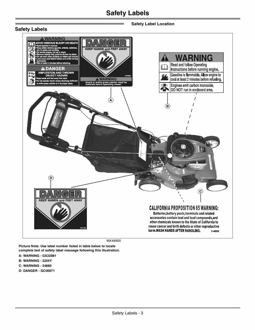
Safety LabelsSafety Label Location
MX49900
Picture Note: Use label number listed in table below to locate complete text of safety label message following this illustration.
A- WARNING - GX22881
B- WARNING - 3255Y
C- WARNING - 34880
D- DANGER - GC00671
A
B
C
D
Safety Labels - 3
Safety Labels
Safety LabelsUnderstanding The Machine Safety LabelsThe machine safety labels shown in this section are placed in important areas on your machine to draw attention to potential safety hazards.
On your machine safety labels, the words DANGER, WARNING, and CAUTION are used with this safety-alert symbol. DANGER identifies the most serious hazards.
The operator’s manual also explains any potential safety hazards whenever necessary in special safety messages that are identified with the word, CAUTION, and the safety-alert symbol.
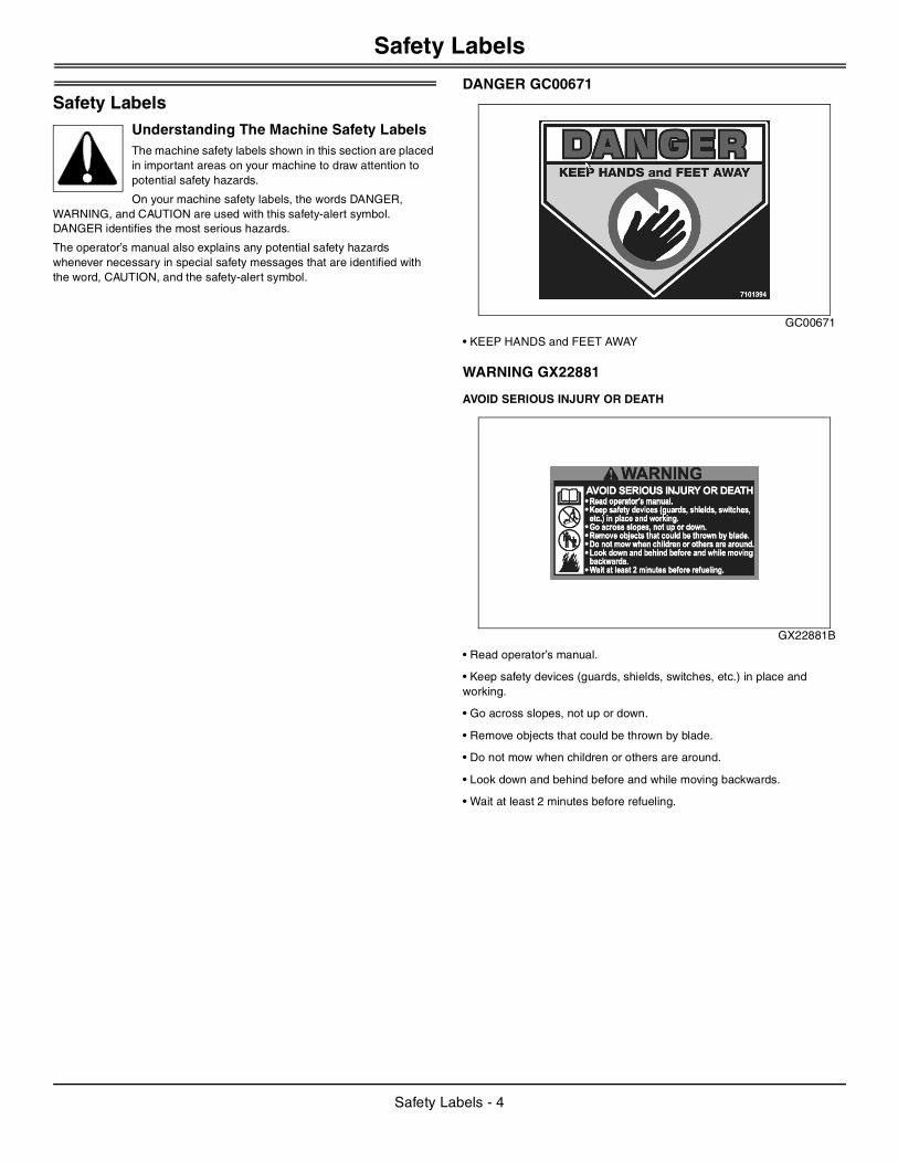
DANGER GC00671
GC00671
• KEEP HANDS and FEET AWAY
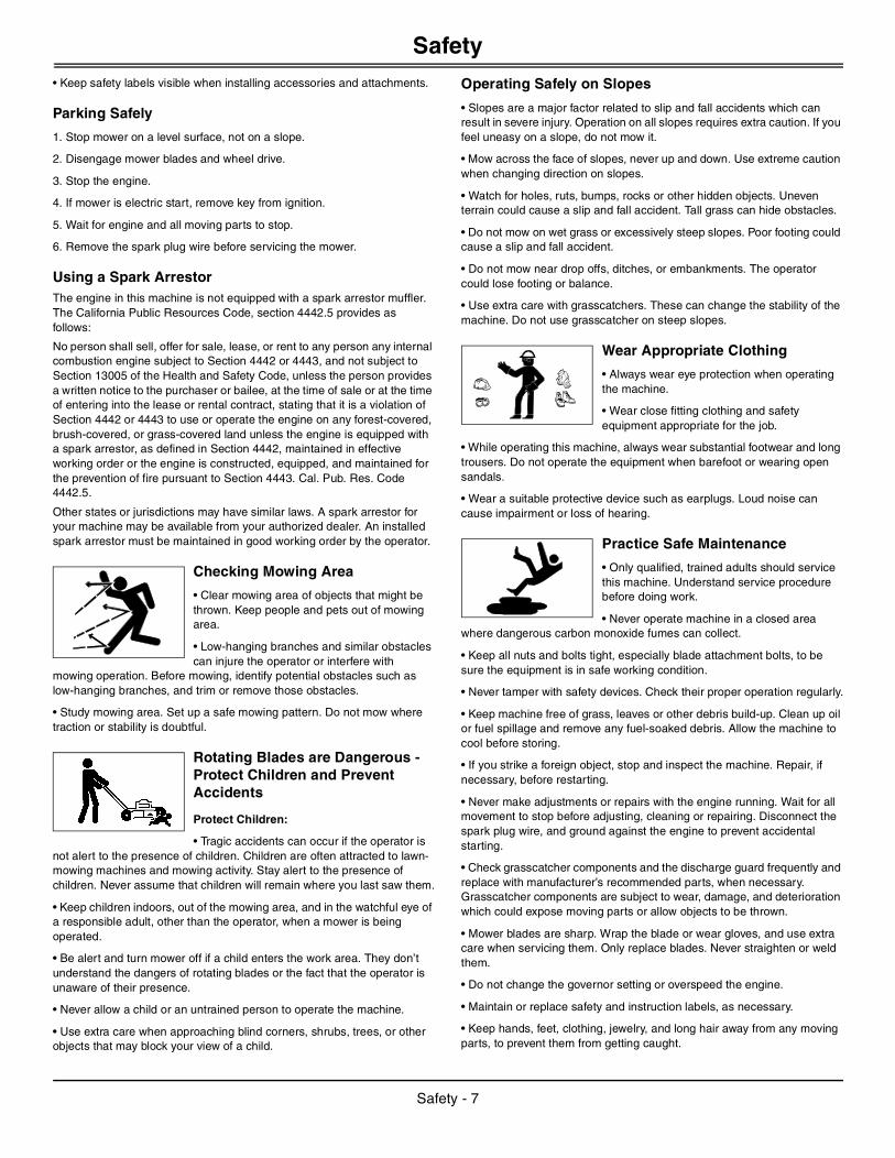
WARNING GX22881
AVOID SERIOUS INJURY OR DEATH
GX22881B
• Read operator’s manual.
• Keep safety devices (guards, shields, switches, etc.) in place and working.
• Go across slopes, not up or down.
• Remove objects that could be thrown by blade.
• Do not mow when children or others are around.
• Look down and behind before and while moving backwards.
• Wait at least 2 minutes before refueling.
Safety Labels - 4

Safety Labels
DANGER GX22881
AMPUTATION AND THROWN OBJECT HAZARD
GX22881C
• Keep hands and feet away from deck.
• Do not operate mower unless discharge deflector or entire grass catcher is in its proper place.
DANGER GX22881
GX22881D
• KEEP HANDS and FEET AWAY
WARNING GX22881
GX22881E
• Guard or entire grass catcher must be installed before operating mower.
WARNING 34880
MX28303
CALIFORNIA PROPOSITION 65 WARNING: Batteries, battery posts, terminals and related accessories contain lead and lead compounds, and other chemicals known to the State of California to cause cancer and birth defects or other reproductive harm. WASH HANDS AFTER HANDLING.
WARNING 3255Y
GX3255Y
• Read and follow Operating Instructions before running engine.
• Gasoline is flammable. Allow engine to cool at least 2 minutes before refueling.
• Engines emit carbon monoxide, DO NOT run in enclosed area.
Emission Control System Certification Label
NOTE: Tampering with emission controls and components by unauthorized personnel may result in severe fines or penalties. Emission controls and components can only be adjusted by EPA and/or CARB authorized service centers. Contact your John Deere Retailer concerning emission controls and component questions.
The presence of an emissions label signifies that the engine has been certified with the United States Environmental Protection Agency (EPA) and/or California Air Resources Board (CARB).
The emissions warranty applies only to those engines marketed by John Deere that have been certified by the EPA and/or CARB; and used in the United States and Canada in off-road mobile equipment.
Emission Compliance PeriodIf your engine has the emission compliance category listed on the emission control system certification or air index label, this indicates the number of operating hours for which the engine has been certified to meet EPA and/or CARB emission requirements. The following table provides the engine compliance period in hours associated with the category found on the certification label.
Safety Labels - 5

Safety
CertificationYour mower has been certified for compliance with American National Standards Institute B-71.1-2003, “Safety Specifications” for Power Lawn Mowers, Lawn and Garden Tractors, and Lawn Tractors.
SafetyOperating Safely
• This cutting machine is capable of amputating hands and feet and throwing objects. Failure to observe the following safety instructions could result in serious injury or death.
• Read, understand and follow all instructions on the machine and in the manual before starting. Be thoroughly familiar with the controls and the proper use of the machine before starting.
• Do not put hands or feet near or under the machine. Keep clear of the discharge opening at all times.
• Only allow responsible adults, who are familiar with the instructions, to operate this machine. Local regulations may restrict the age of the operator.
• Clear the area of objects such as rocks, toys, wire, and similar items which could be thrown by the blade. Stay behind the handle when the engine is running.
• Be sure the area is clear of bystanders before operating. Stop machine if anyone enters the area.
• Do not operate the mower barefooted or while wearing sandals. Always wear substantial footwear.
• Do not pull machine backward unless absolutely necessary. Always look down and behind before and while moving backward.
• Never direct discharged material toward anyone. Avoid discharging material against a wall or obstruction. Material may ricochet back toward the operator. Stop the blade when crossing gravel surfaces.
• Do not operate machine without the entire grasscatcher, discharge guard, rear guard, or other safety protective devices in place and working. Never operate with the discharge deflector raised, removed, or altered, unless using a grasscatcher.
• Never leave a running machine unattended.
• Stop the engine and wait until the blade comes to complete stop before cleaning the machine, removing grasscatcher, or unclogging the discharge guard.
• Operate machine only in daylight or good artificial light.
• Do not operate the mower while under the influence of alcohol or drugs.
• Never operate mower in wet grass. Always be sure of your footing. Walk; never run.
• Disengage the drive system, if so equipped, before starting the engine.
• If the machine should start to vibrate abnormally, stop the engine and check for the cause immediately. Vibration is generally a warning of trouble.
• Always wear safety goggles or safety glasses with side shields when operating mower.
• See manufacturer’s instructions for proper operation and installation of accessories. Only use accessories approved by the manufacturer.
• Inspect machine before you operate. Be sure hardware is tight. Repair or replace damaged, badly worn, or missing parts. Make any necessary adjustments before you operate.
• Before using, always visually inspect to see that the blades, blade bolts and the mower assembly are not worn and damaged. Replace worn and damaged blades as needed.
• Make sure spark plug, muffler, fuel cap and air cleaner are in place before starting the engine.
Agency Category Hours
EPA C 125
EPA B 250
EPA A 500
CARB Moderate 125
CARB Intermediate 250
CARB Extended 500
Safety - 6
Safety
• Keep safety labels visible when installing accessories and attachments.Parking Safely
1. Stop mower on a level surface, not on a slope.
2. Disengage mower blades and wheel drive.
3. Stop the engine.
4. If mower is electric start, remove key from ignition.
5. Wait for engine and all moving parts to stop.
6. Remove the spark plug wire before servicing the mower.
Using a Spark ArrestorThe engine in this machine is not equipped with a spark arrestor muffler. The California Public Resources Code, section 4442.5 provides as follows:
No person shall sell, offer for sale, lease, or rent to any person any internal combustion engine subject to Section 4442 or 4443, and not subject to Section 13005 of the Health and Safety Code, unless the person provides a written notice to the purchaser or bailee, at the time of sale or at the time of entering into the lease or rental contract, stating that it is a violation of Section 4442 or 4443 to use or operate the engine on any forest-covered, brush-covered, or grass-covered land unless the engine is equipped with a spark arrestor, as defined in Section 4442, maintained in effective working order or the engine is constructed, equipped, and maintained for the prevention of fire pursuant to Section 4443. Cal. Pub. Res. Code 4442.5.
Other states or jurisdictions may have similar laws. A spark arrestor for your machine may be available from your authorized dealer. An installed spark arrestor must be maintained in good working order by the operator.
Checking Mowing Area
• Clear mowing area of objects that might be thrown. Keep people and pets out of mowing area.
• Low-hanging branches and similar obstacles can injure the operator or interfere with
mowing operation. Before mowing, identify potential obstacles such as low-hanging branches, and trim or remove those obstacles.
• Study mowing area. Set up a safe mowing pattern. Do not mow where traction or stability is doubtful.
Rotating Blades are Dangerous - Protect Children and Prevent Accidents
Protect Children:
• Tragic accidents can occur if the operator is not alert to the presence of children. Children are often attracted to lawn-mowing machines and mowing activity. Stay alert to the presence of children. Never assume that children will remain where you last saw them.
• Keep children indoors, out of the mowing area, and in the watchful eye of a responsible adult, other than the operator, when a mower is being operated.
• Be alert and turn mower off if a child enters the work area. They don’t understand the dangers of rotating blades or the fact that the operator is unaware of their presence.
• Never allow a child or an untrained person to operate the machine.
• Use extra care when approaching blind corners, shrubs, trees, or other objects that may block your view of a child.
Operating Safely on Slopes
• Slopes are a major factor related to slip and fall accidents which can result in severe injury. Operation on all slopes requires extra caution. If you feel uneasy on a slope, do not mow it.
• Mow across the face of slopes, never up and down. Use extreme caution when changing direction on slopes.
• Watch for holes, ruts, bumps, rocks or other hidden objects. Uneven terrain could cause a slip and fall accident. Tall grass can hide obstacles.
• Do not mow on wet grass or excessively steep slopes. Poor footing could cause a slip and fall accident.
• Do not mow near drop offs, ditches, or embankments. The operator could lose footing or balance.
• Use extra care with grasscatchers. These can change the stability of the machine. Do not use grasscatcher on steep slopes.
Wear Appropriate Clothing
• Always wear eye protection when operating the machine.
• Wear close fitting clothing and safety equipment appropriate for the job.
• While operating this machine, always wear substantial footwear and long trousers. Do not operate the equipment when barefoot or wearing open sandals.
• Wear a suitable protective device such as earplugs. Loud noise can cause impairment or loss of hearing.
Practice Safe Maintenance
• Only qualified, trained adults should service this machine. Understand service procedure before doing work.
• Never operate machine in a closed area where dangerous carbon monoxide fumes can collect.
• Keep all nuts and bolts tight, especially blade attachment bolts, to be sure the equipment is in safe working condition.
• Never tamper with safety devices. Check their proper operation regularly.
• Keep machine free of grass, leaves or other debris build-up. Clean up oil or fuel spillage and remove any fuel-soaked debris. Allow the machine to cool before storing.
• If you strike a foreign object, stop and inspect the machine. Repair, if necessary, before restarting.
• Never make adjustments or repairs with the engine running. Wait for all movement to stop before adjusting, cleaning or repairing. Disconnect the spark plug wire, and ground against the engine to prevent accidental starting.
• Check grasscatcher components and the discharge guard frequently and replace with manufacturer’s recommended parts, when necessary. Grasscatcher components are subject to wear, damage, and deterioration which could expose moving parts or allow objects to be thrown.
• Mower blades are sharp. Wrap the blade or wear gloves, and use extra care when servicing them. Only replace blades. Never straighten or weld them.
• Do not change the governor setting or overspeed the engine.
• Maintain or replace safety and instruction labels, as necessary.
• Keep hands, feet, clothing, jewelry, and long hair away from any moving parts, to prevent them from getting caught.
Safety - 7
Assembly
• Never attempt to make wheel height adjustments while the engine is running.• Keep all parts in good condition and properly installed. Fix damage immediately. Replace worn or broken parts.
• Do not strike the flywheel with a hammer or hard object because the flywheel may later shatter during operation.
Prevent Fires
• Machine fires and structure fires can occur if a machine is stored before allowing it to cool, if debris is not removed from critical areas of the machine, or if machine is stored near combustible materials.
• Remove grass and debris completely from engine compartment and muffler area, and from on top of the mower deck, before and after operating machine, especially after mowing or mulching in dry conditions.
• Empty any grasscatcher bags or containers completely before storing.
• Always shut off fuel when storing or transporting machine, if the machine has a fuel shutoff.
• Do not store machine near an open flame or source of ignition, such as a water heater or furnace.
• Check fuel lines, tank, cap, and fittings frequently for cracks or leaks. Replace if necessary.
Handling Fuel Safely
To avoid personal injury or property damage, use extreme care in handling fuel. Fuel is extremely flammable and fuel vapors are explosive:
• Extinguish all cigarettes, cigars, pipes, and other sources of ignition.
• Use only an approved fuel container. Use only non-metal, portable fuel containers approved by the Underwriter’s Laboratory (U.L.) or the American Society for Testing & Materials (ASTM). If using a funnel, make sure it is plastic and has no screen or filter.
• Never remove the fuel tank cap or add fuel with the engine running. Allow engine to cool before refueling.
• Never add fuel to or drain fuel from the machine indoors. Move machine outdoors and provide adequate ventilation.
• Clean up spilled fuel immediately. If fuel is spilled on clothing, change clothing immediately. If fuel is spilled near machine, do not attempt to start the engine but move the machine away from the area of spillage. Avoid creating any source of ignition until fuel vapors have dissipated.
• Never store the machine or fuel container where there is an open flame, spark, or pilot light such as on a water heater or other appliance.
• Prevent fire and explosion caused by static electric discharge. Static electric discharge can ignite fuel vapors in an ungrounded fuel container.
• Never fill containers inside a vehicle or on a truck or trailer bed with a plastic liner. Always place containers on the ground away from your vehicle before fueling.
• Remove fuel-powered equipment from the truck or trailer and refuel it on the ground. If this is not possible, then refuel such equipment with a portable container, rather than from a fuel dispenser nozzle.
• Keep the nozzle in contact with the rim of the fuel tank or container opening at all times until the fueling is complete. Do not use a nozzle lock-open device.
• Never overfill fuel tank. Replace fuel tank cap and tighten securely.
• Replace all fuel container caps securely after use.
• For gasoline engines, do not use gas with methanol. Methanol is harmful to your health and to the environment.
Handling Waste Product and Chemicals Waste products, such as, used oil, fuel, coolant, brake fluid, and batteries, can harm the environment and people:
• Do not use beverage containers for waste fluids - someone may drink from them.
• See your local Recycling Center or authorized dealer to learn how to recycle or get rid of waste products.
• A Material Safety Data Sheet (MSDS) provides specific details on chemical products: physical and health hazards, safety procedures, and emergency response techniques. The seller of the chemical products used with your machine is responsible for providing the MSDS for that product.
AssemblyPrepare Handle Assembly
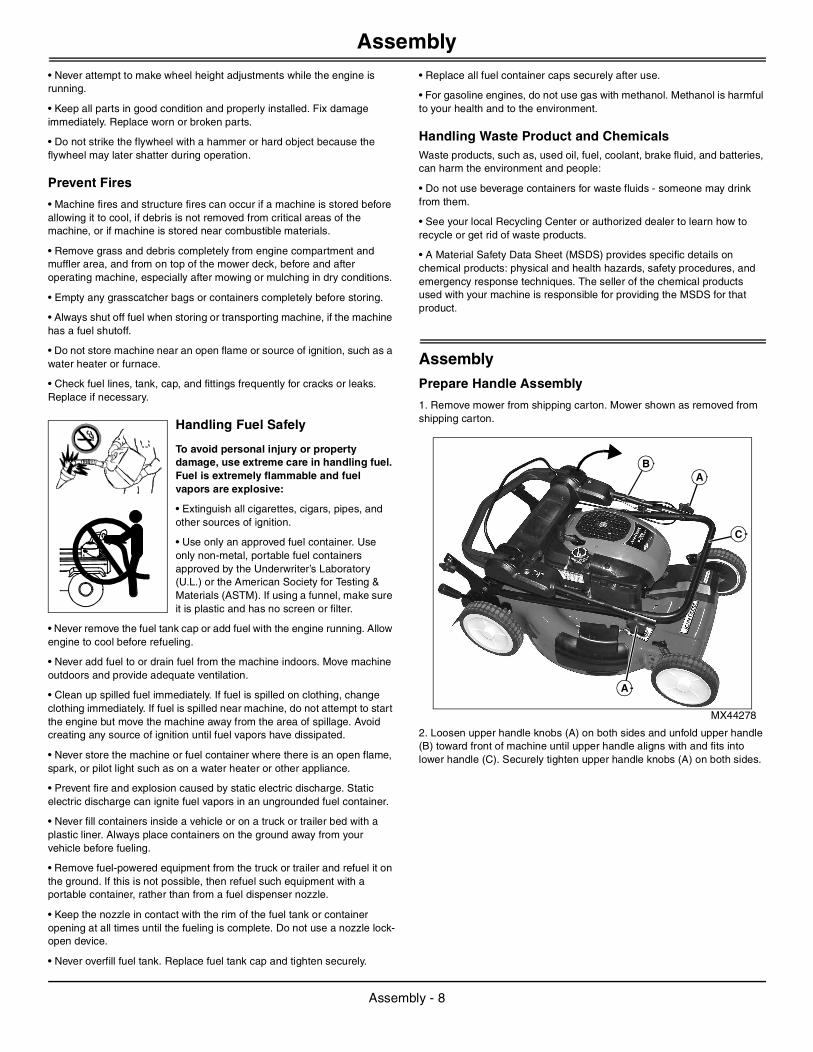
1. Remove mower from shipping carton. Mower shown as removed from shipping carton.
MX44278
2. Loosen upper handle knobs (A) on both sides and unfold upper handle (B) toward front of machine until upper handle aligns with and fits into lower handle (C). Securely tighten upper handle knobs (A) on both sides.
B
C
A
A
Assembly - 8
Assembly
MX44279
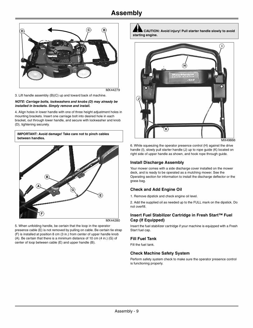
3. Lift handle assembly (B)(C) up and toward back of machine.
NOTE: Carriage bolts, lockwashers and knobs (D) may already be installed in brackets. Simply remove and install.
4. Align holes in lower handle with one of three height adjustment holes in mounting brackets. Insert one carriage bolt into desired hole in each bracket, out through lower handle, and secure with lockwasher and knob (D), tightening securely.
MX44280
5. When unfolding handle, be certain that the loop in the operator presence cable (E) is not removed by pulling on cable. Be certain tie strap (F) is installed at position 8 cm (3 in.) from center of upper handle knob (A). Be certain that there is a minimum distance of 10 cm (4 in.) (G) of center of loop between cable (E) and upper handle (B).
MX49866
6. While squeezing the operator presence control (H) against the drive handle (I), slowly pull starter handle (J) up to rope guide (K) located on right side of upper handle as shown, and hook rope through guide.
Install Discharge AssemblyYour mower comes with a side discharge cover installed on the mower deck, and is ready to be operated as a mulching mower. See the Operating section for information to install the discharge deflector or the grass bag.
Check and Add Engine Oil
1. Remove dipstick and check engine oil level.
2. Add the supplied oil as needed up to the FULL mark on the dipstick. Do not overfill.
Insert Fuel Stabilizer Cartridge in Fresh Start™ Fuel Cap (If Equipped)Insert the fuel stabilizer cartridge if your machine is equipped with a Fresh Start fuel cap.
Fill Fuel TankFill the fuel tank.
Check Machine Safety SystemPerform safety system check to make sure the operator presence control is functioning properly.
IMPORTANT: Avoid damage! Take care not to pinch cables between handles.
BCD
B
E
G
F
A
c CAUTION: Avoid injury! Pull starter handle slowly to avoid starting engine.
J
K
H
I
Assembly - 9

Operating Controls
Operating ControlsOperator Station Controls (JS28, JS38)
MX49899 Picture Note: JS28 model shown.
K
I
N
H
L
K
A
C
B
J
G
E
M
F
JD
Key Description Key Description
A MowMentum™ Drive Handle H Air Cleaner Cover
B Operator Presence Control I Side Discharge Cover
C Drive Cable Adjuster J Rear Wheel Cutting Height Adjustment Lever (JS28)
All Wheel Cutting Height Adjustment Lever (JS38)
D Rear Door, Spring-Loaded K Handle Height Adjustment
E Fuel Fill Cap L Grass Bag
F Oil Fill and Dipstick M Starter Handle
G Front Cutting Height Adjustment Levers (JS28) N Neutral Lock
Operating Controls - 10
Operating Controls
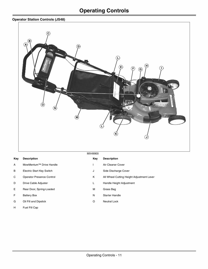
Operator Station Controls (JS48)
MX49900
O
KJ
GF
L
L
AD
C
B
HI
M
N
E
Key Description Key Description
A MowMentum™ Drive Handle I Air Cleaner Cover
B Electric Start Key Switch J Side Discharge Cover
C Operator Presence Control K All Wheel Cutting Height Adjustment Lever
D Drive Cable Adjuster L Handle Height Adjustment
E Rear Door, Spring-Loaded M Grass Bag
F Battery Box N Starter Handle
G Oil Fill and Dipstick O Neutral Lock
H Fuel Fill Cap
Operating Controls - 11

Operating
Operating Daily Operating Checklist
❏ Test safety systems.
❏ Make sure all guards, deflectors and covers are in place and tightened.
❏ Check engine oil level.
❏ Check fuel level.
❏ Check fuel stabilizer cartridge in fuel cap.
❏ Check that handle knobs are tight.
❏ Check for proper cutting height.
❏ Remove grass and debris from machine.
❏ Check area below machine for leaks.
Adjusting Cutting Height
JS28 model is front wheel drive, with separate wheel adjustment levers on each wheel.
JS38 and JS48 models are rear wheel drive with a single height adjustment lever at the right rear wheel.
JS28
Each wheel has a height adjustment lever than raises and lowers the wheel individually.
1. Park machine safely. (See Parking Safely in the Safety Section.)
NOTE: All four wheel heights are adjusted individually. The front height of cut levers can be set over the bent tabs and between them to obtain all nine positions. All wheels should be set in the same position to ensure even grass cutting.
MX49867
Picture Note: Right side shown.
2. Pull the height adjusting lever (J) on each wheel outward and move to the desired cutting height. The lowest cutting height is location (A). The highest cutting height is location (I).
JS38, JS48
A single height adjustment lever at the right rear wheel is connected to linkage which raises or lowers the mower deck equally at all four wheels simultaneously.
1. Park machine safely. (See Parking Safely in the Safety Section.)
c CAUTION: Avoid injury! Rotating blades are dangerous and can cut fingers and toes. Stop engine and wait for blade to stop rotating before adjusting cutting height.
Key Cutting Height Adjustments
(A) 30 mm (1.2 in.)
(B) 38 mm (1.5 in.)
(C) 48 mm (1.9 in.)
(D) 56 mm (2.2 in.)
(E) 66 mm (2.6 in.)
(F) 76 mm (3.0 in.)
(G) 86 mm (3.4 in.)
(H) 97 mm (3.8 in.)
(I) 107 mm (4.2 in.)
J
A
I
Operating - 12
Operating
MX49870
Picture Note: Right side shown.
MX49871
Picture Note: Left side shown.
2. Pull the height adjusting lever (J) outward and move to the desired cutting height. The lowest cutting height is location (A). The highest cutting height is location (I).
3. Linkage (K) raises and lowers the four wheels simultaneously.
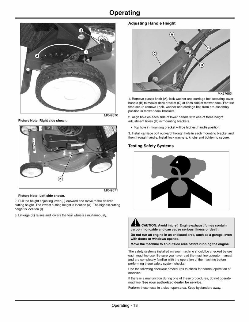
Adjusting Handle Height
MX27683
1. Remove plastic knob (A), lock washer and carriage bolt securing lower handle (B) to mower deck bracket (C) at each side of mower deck. For first time set-up remove knob, washer and carriage bolt from pre-assembly position in mower deck brackets.
2. Align hole on each side of lower handle with one of three height adjustment holes (D) in mounting brackets.
• Top hole in mounting bracket will be highest handle position.
3. Install carriage bolt outward through hole in each mounting bracket and then through handle. Install lock washers, knobs and tighten to secure.
Testing Safety Systems
The safety systems installed on your machine should be checked before each machine use. Be sure you have read the machine operator manual and are completely familiar with the operation of the machine before performing these safety system checks.
Use the following checkout procedures to check for normal operation of machine.
If there is a malfunction during one of these procedures, do not operate machine. See your authorized dealer for service.
Perform these tests in a clear open area. Keep bystanders away.
I
J
A
K
c CAUTION: Avoid injury! Engine exhaust fumes contain carbon monoxide and can cause serious illness or death.
Do not run an engine in an enclosed area, such as a garage, even with doors or windows opened.
Move the machine to an outside area before running the engine.
C
B
A
D
Operating - 13
Operating
Testing Operator Presence Control
1. Hold the operator presence control against the drive handle.
2. Start engine.
3. Release operator presence control.
4. Listen for blade and engine to stop. Do not look under mower to check blade.
Result: Blade and engine should stop within three seconds.
If blade and engine continue to run, there is a problem with your machine safety system. See your John Deere dealer.
Starting and Stopping Engine
Starting Engine-Manual Pull Start
MX49866
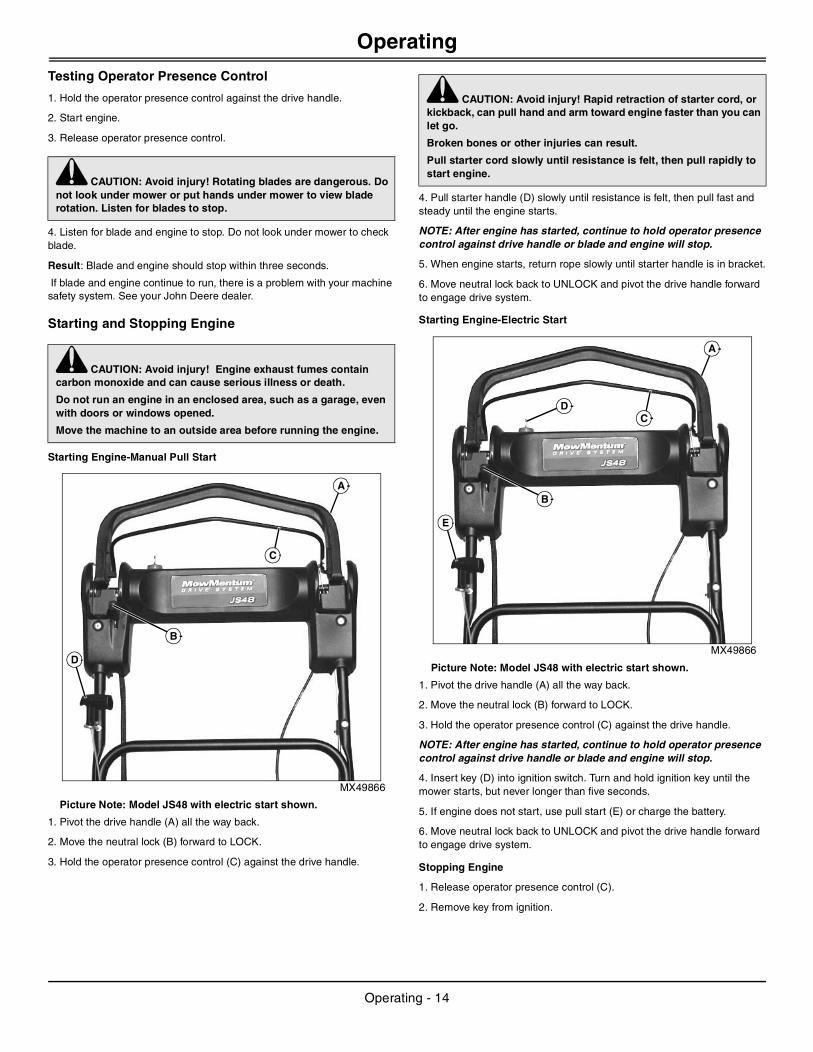
Picture Note: Model JS48 with electric start shown.
1. Pivot the drive handle (A) all the way back.
2. Move the neutral lock (B) forward to LOCK.
3. Hold the operator presence control (C) against the drive handle.
4. Pull starter handle (D) slowly until resistance is felt, then pull fast and steady until the engine starts.
NOTE: After engine has started, continue to hold operator presence control against drive handle or blade and engine will stop.
5. When engine starts, return rope slowly until starter handle is in bracket.
6. Move neutral lock back to UNLOCK and pivot the drive handle forward to engage drive system.
Starting Engine-Electric Start
MX49866
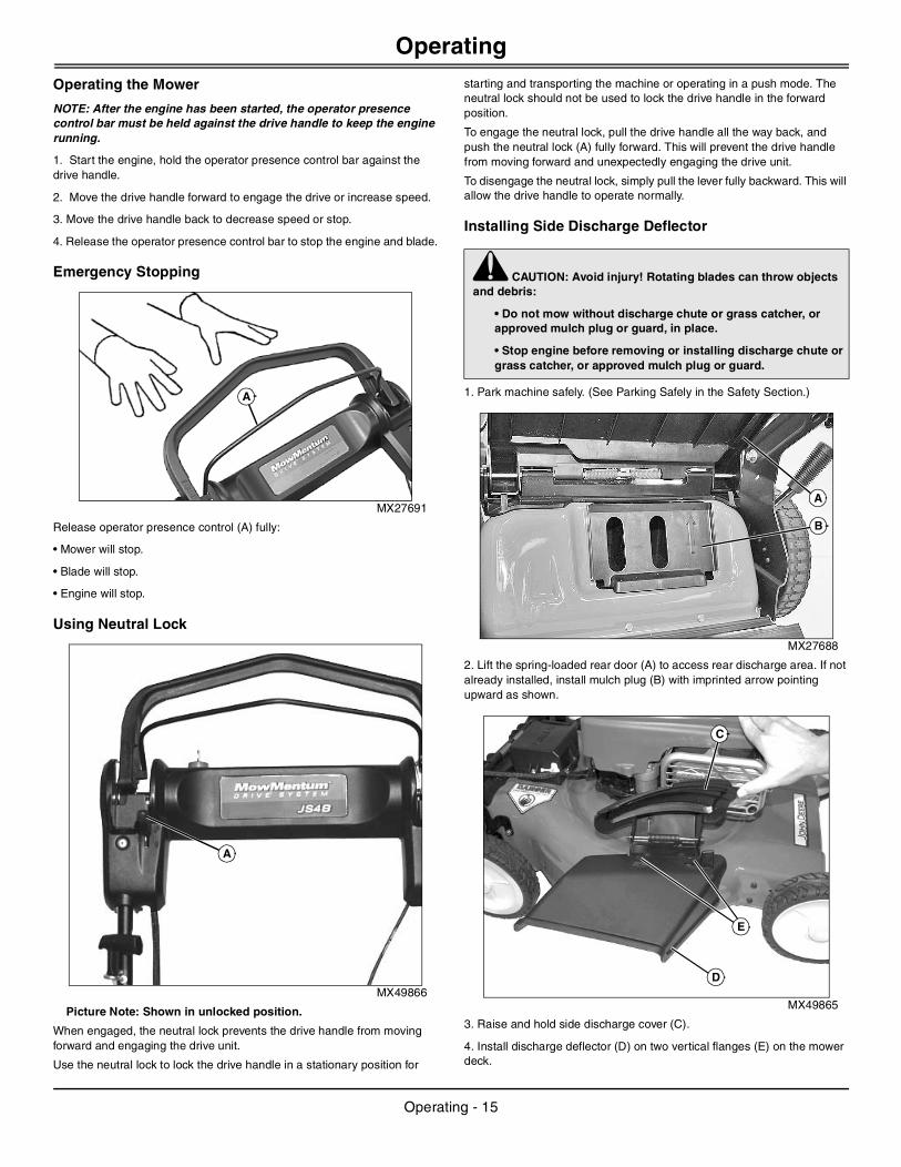
Picture Note: Model JS48 with electric start shown.
1. Pivot the drive handle (A) all the way back.
2. Move the neutral lock (B) forward to LOCK.
3. Hold the operator presence control (C) against the drive handle.
NOTE: After engine has started, continue to hold operator presence control against drive handle or blade and engine will stop.
4. Insert key (D) into ignition switch. Turn and hold ignition key until the mower starts, but never longer than five seconds.
5. If engine does not start, use pull start (E) or charge the battery.
6. Move neutral lock back to UNLOCK and pivot the drive handle forward to engage drive system.
Stopping Engine
1. Release operator presence control (C).
2. Remove key from ignition.
c CAUTION: Avoid injury! Rotating blades are dangerous. Do not look under mower or put hands under mower to view blade rotation. Listen for blades to stop.
c CAUTION: Avoid injury! Engine exhaust fumes contain carbon monoxide and can cause serious illness or death.
Do not run an engine in an enclosed area, such as a garage, even with doors or windows opened.
Move the machine to an outside area before running the engine.
A
C
D
B
c CAUTION: Avoid injury! Rapid retraction of starter cord, or kickback, can pull hand and arm toward engine faster than you can let go.
Broken bones or other injuries can result.
Pull starter cord slowly until resistance is felt, then pull rapidly to start engine.
A
C
E
B
D
Operating - 14
Operating
Operating the Mower
NOTE: After the engine has been started, the operator presence control bar must be held against the drive handle to keep the engine running.
1. Start the engine, hold the operator presence control bar against the drive handle.
2. Move the drive handle forward to engage the drive or increase speed.
3. Move the drive handle back to decrease speed or stop.
4. Release the operator presence control bar to stop the engine and blade.
Emergency Stopping
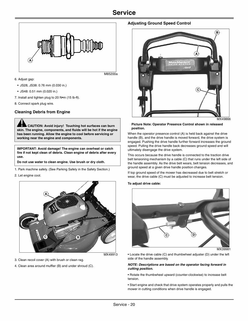
MX27691
Release operator presence control (A) fully:
• Mower will stop.
• Blade will stop.
• Engine will stop.
Using Neutral Lock
MX49866
Picture Note: Shown in unlocked position.
When engaged, the neutral lock prevents the drive handle from moving forward and engaging the drive unit.
Use the neutral lock to lock the drive handle in a stationary position for
starting and transporting the machine or operating in a push mode. The neutral lock should not be used to lock the drive handle in the forward position.
To engage the neutral lock, pull the drive handle all the way back, and push the neutral lock (A) fully forward. This will prevent the drive handle from moving forward and unexpectedly engaging the drive unit.
To disengage the neutral lock, simply pull the lever fully backward. This will allow the drive handle to operate normally.
Installing Side Discharge Deflector
1. Park machine safely. (See Parking Safely in the Safety Section.)
MX27688
2. Lift the spring-loaded rear door (A) to access rear discharge area. If not already installed, install mulch plug (B) with imprinted arrow pointing upward as shown.
MX49865
3. Raise and hold side discharge cover (C).
4. Install discharge deflector (D) on two vertical flanges (E) on the mower deck.
A
A
c CAUTION: Avoid injury! Rotating blades can throw objects and debris:
• Do not mow without discharge chute or grass catcher, or approved mulch plug or guard, in place.
• Stop engine before removing or installing discharge chute or grass catcher, or approved mulch plug or guard.
B
A
C
D
E
Operating - 15

Operating
5. Lower side discharge cover and allow it to rest against side discharge deflector. The spring tension on the side discharge cover will secure the side discharge deflector in place.Installing Grass Bag
1. Park machine safely. (See Parking Safely in the Safety Section.)
MX27688
2. LIft the spring-loaded rear cover (A) to access the mulch plug.
3. Remove mulch plug (B) from mower.
MX44958
4. Grasp the wire form handle (C) at the top of the grass bag and position the grass bag at the back of the mower housing so that the two hooks (D) on the grass bag frame hook over the rear door pivot shaft (E).
5. Lower the spring-loaded rear door to rest on the grass bag.
6. Store the mulch plug for future use.
Using the Mower for Mulching
1. Install mulch plug.
MX49864
2. Make sure side discharge cover (A) is closed.
3. Adjust cutting height to remove only 1/3 of the grass at a time.
4. Raise cutting height, if grass clumping occurs.
c CAUTION: Avoid injury! Rotating blades can throw objects and debris:
• Do not mow without discharge chute or grass catcher, or approved mulch plug or guard, in place.
• Stop engine before removing or installing discharge chute or grass catcher, or approved mulch plug or guard.
A
B
C
D
E
A
Operating - 16

Service Intervals
Service IntervalsServicing Your Machine
Please use the following timetables to perform routine maintenance on your machine.
Before Each Use
• Check hardware tightness.
• Fill tank with fresh fuel.
• Check engine oil level.
• Clean debris from around muffler, engine cooling fins, and engine cover.
• Clean debris from mower.
• Test safety systems.
Break In - After First 5 Hours of Operation
• Change engine oil.
Every 25 Hours or Once a Year
• Change engine oil.
• Replace oil filter (JS48).
• Check air filter paper element, replace if very dirty.
• Check blade bolt for tightness.
• Clean drive belt and transmission area.
• Check drive belt for wear and tension.
Every 50 Hours or Once a Year
• Check spark arrestor (if equipped) and clean if necessary.
Every 100 Hours or Once a Year
• Replace spark plug.
• Replace air filter paper element.
ServiceAdjusting Carburetor
NOTE: Carburetor is calibrated by the engine manufacturer and should not require any adjustments.
If engine is operated at altitudes above 1829 m (6,000 ft), some carburetors may require a special high altitude main jet. See your John Deere dealer.
If engine is hard to start or runs rough, check the Troubleshooting section of this manual.
After performing the checks in the troubleshooting section and your engine is still not performing correctly, contact your John Deere dealer.
Avoid Fumes
Engine OilUse oil viscosity based on the expected air temperature range during the period between oil changes.
NOTE: Below 40° F (4° C) the use of SAE30 will result in hard starting. Above 80° F (27° C) the use of 10W-30 may cause increased oil consumption. Check oil level more frequently.
The following John Deere oils are preferred:
• TORQ-GARD SUPREME™ (SAE30)
The following John Deere oils are also recommended, based on their specified temperature range:
• TURF-GARD™
• PLUS- 4™
Other oils may be used if above John Deere oils are not available, provided they meet the following specification:
• API Service Classification SJ or higher
Checking Engine Oil
1. Park machine safely. (See Parking Safely in the Safety Section.)
IMPORTANT: Avoid damage! Operating in extreme conditions may require more frequent service intervals:
• Engine components may become dirty or plugged when operating in extreme heat, dust or other severe conditions.
• Engine oil can degrade if machine is operated constantly at slow or low engine speeds or for frequent short periods of time.
c CAUTION: Avoid injury! Engine exhaust fumes contain carbon monoxide and can cause serious illness or death.
Do not run an engine in an enclosed area, such as a garage, even with doors or windows opened.
Move the machine to an outside area before running the engine.
32
0 10 20 30 40-10-20-30
-20 0 20 40 60 80 100
50
122
-40
-40F
C
SAE 30
SAE 10W-30
Service Intervals - 17

Service
MX49913
Picture Note: JS28 shown. JS38 similar.
MX27693
Picture Note: JS48 shown.
2. Clean area around dipstick (A or B).
3. Remove dipstick and wipe clean.
4. Install and tighten dipstick.
5. Remove dipstick.
6. Check oil level on dipstick. Oil must be between ADD and FULL marks.
7. If oil level is low, add oil to bring oil level no higher than FULL mark on dipstick. Do not overfill.
8. Install and tighten dipstick.
Changing Engine Oil
NOTE: Be sure the fuel tank is at least half empty before changing the oil. Change oil after mowing or run the engine briefly to lower the fuel in the tank to the appropriate level.
1. Run engine for at least five minutes to warm up oil.
2. Park machine safely. (See Parking Safely in the Safety Section.)
3. Remove dipstick.
4. Position drain pan and turn mower onto its side to drain engine oil from the dipstick filler tube location into the drain pan.
5. After oil has drained, return mower to an upright position and clean around dipstick filler tube.
6. Add oil through dipstick filler tube. Check oil level and continue to add oil to FULL mark on dipstick.
7. Install dipstick and connect spark plug wire.
Servicing Air Cleaner Element
1. Park machine safely. (See Parking Safely in the Safety Section.)
2. Let engine cool.
JS28 and JS38
MX49904
1. Clean dirt and debris from the air cleaner cover (A).
2. Loosen screw (B) and tilt cover down against side discharge cover.
IMPORTANT: Avoid damage! Do not overfill. Overfilling with oil can cause the engine to not start or hard starting. If oil is over the FULL mark on the dipstick, drain oil to reduce oil level in engine.
A
B
c CAUTION: Avoid injury! Touching hot surfaces can burn skin. The engine, components, and fluids will be hot if the engine has been running. Keep hands and body away from hot surfaces when servicing or working near the engine and components.
IMPORTANT: Avoid damage! Do not overfill. Overfilling can cause smoking, hard starting, fouling of spark plug, and oil saturation of air filter.
c CAUTION: Avoid injury! Touching hot surfaces can burn skin. The engine, components, and fluids will be hot if the engine has been running. Allow the engine to cool before servicing or working near the engine and components.
B
A
Service - 18

Service
MX49907
3. Inspect the paper element (C) without removing it. If the paper element is damaged or dirty, tilt it outward to remove and replace it with a new element.
4. Clean air cleaner base carefully, preventing any dirt from falling into carburetor.
5. Install new paper element into air cleaner base.
6. Close cover and tighten screw.
JS48
MX27694
1. Clean dirt and debris from the air cleaner cover (A).
2. Loosen knob (B) and remove cover from mower.
MX27695
3. Inspect the foam precleaner (C) without removing it. If the foam precleaner is dirty:
• Remove the filter carefully, leaving the paper element in the air cleaner housing.
• Wash the precleaner in a solution of warm water and liquid detergent.
• Rinse precleaner thoroughly. Squeeze out excess water in a dry cloth until precleaner is completely dry.
4. Inspect the paper element without removing it. If the paper element is damaged or dirty, remove and replace it with a new element.
5. Clean air cleaner base carefully, preventing any dirt from falling into carburetor.
6. Install dry foam precleaner onto paper element and install into air cleaner base.
7. Install cover and tighten knob.
Cleaning and Gapping Spark Plug
1. Park machine safely. (See Parking Safely in the Safety Section.)
2. Let engine cool.
3. Disconnect spark plug wire. Remove spark plug.
4. Clean spark plug carefully with a wire brush.
5. Inspect spark plug and replace if damaged.
IMPORTANT: Avoid damage! Dirt and debris can enter the engine through a damaged filter element:
• Do not wash paper element.
• Do not attempt to clean paper element by tapping against another object.
• Do not use pressurized air to clean element.
• Replace element only if it is very dirty, damaged or the seal is cracked.
A
C
AB
IMPORTANT: Avoid damage! Dirt and debris can enter the engine through a damaged filter element:
• Do not wash paper element.
• Do not attempt to clean paper element by tapping against another object.
• Do not use pressurized air to clean element.
• Replace element only if it is very dirty, damaged or the seal is cracked.
c CAUTION: Avoid injury! Touching hot surfaces can burn skin. The engine, components, and fluids will be hot if the engine has been running. Allow the engine to cool before servicing or working near the engine and components.
C
Service - 19
Service
M85200a
6. Adjust gap:
• JS28, JS38: 0.76 mm (0.030 in.)
• JS48: 0.51 mm (0.020 in.)
7. Install and tighten plug to 20 N•m (15 lb-ft).
8. Connect spark plug wire.
Cleaning Debris from Engine
1. Park machine safely. (See Parking Safely in the Safety Section.)
2. Let engine cool.
MX49913
3. Clean recoil cover (A) with brush or clean rag.
4. Clean area around muffler (B) and under shroud (C).
Adjusting Ground Speed Control
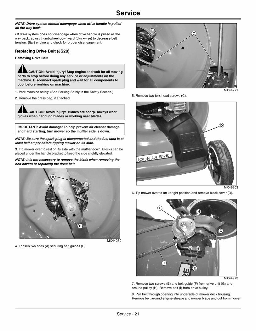
MX49866
Picture Note: Operator Presence Control shown in released position.
When the operator presence control (A) is held back against the drive handle (B), and the drive handle is moved forward, the drive system is engaged. Pushing the drive handle further forward increases the ground speed. Pulling the drive handle back decreases ground speed and will ultimately disengage the drive system.
This occurs because the drive handle is connected to the traction drive belt tensioning mechanism by a cable (C) that runs under the left side of the handle assembly. As the drive belt wears, belt tension decreases, and ground speed at a given drive handle position changes.
If top ground speed of the mower has decreased due to belt stretch or wear, the drive cable (C) must be adjusted to increase belt tension.
To adjust drive cable:
MX39981
• Locate the drive cable (C) and thumbwheel adjuster (D) under the left side of the handle assembly.
NOTE: Descriptions are based on the operator facing forward in cutting position.
• Rotate the thumbwheel upward (counter-clockwise) to increase belt tension.
• Start engine and check that drive system operates properly and pulls the mower in cutting conditions when drive handle is engaged.
c CAUTION: Avoid injury! Touching hot surfaces can burn skin. The engine, components, and fluids will be hot if the engine has been running. Allow the engine to cool before servicing or working near the engine and components.
IMPORTANT: Avoid damage! The engine can overheat or catch fire if not kept clean of debris. Clean engine of debris after every use.
Do not use water to clean engine. Use brush or dry cloth.
A
A
BC
B
A
C
C D
Service - 20
Service
NOTE: Drive system should disengage when drive handle is pulled all the way back.• If drive system does not disengage when drive handle is pulled all the way back, adjust thumbwheel downward (clockwise) to decrease belt tension. Start engine and check for proper disengagement.
Replacing Drive Belt (JS28)
Removing Drive Belt
1. Park machine safely. (See Parking Safely in the Safety Section.)
2. Remove the grass bag, if attached.
NOTE: Be sure the spark plug is disconnected and the fuel tank is at least half empty before tipping mower on its side.
3. Tip mower over to rest on its side with the muffler down. Blocks can be placed under the handle bracket to keep the side slightly elevated.
NOTE: It is not necessary to remove the blade when removing the belt covers or replacing the drive belt.
MX44270
4. Loosen two bolts (A) securing belt guides (B).
MX44271
5. Remove two torx head screws (C).
MX49903
6. Tip mower over to an upright position and remove black cover (D).
MX44273
7. Remove two screws (E) and belt guide (F) from drive unit (G) and around pulley (H). Remove belt (I) from drive pulley.
8. Pull belt through opening into underside of mower deck housing. Remove belt around engine sheave and mower blade and out from mower
c CAUTION: Avoid injury! Stop engine and wait for all moving parts to stop before doing any service or adjustments on the machine. Disconnect spark plug and wait for all components to cool before working on machine.
c CAUTION: Avoid injury! Blades are sharp. Always wear gloves when handling blades or working near blades.
IMPORTANT: Avoid damage! To help prevent air cleaner damage and hard starting, turn mower so the muffler side is down.
B
A
C
D
E
FH
I
G
Service - 21
Service
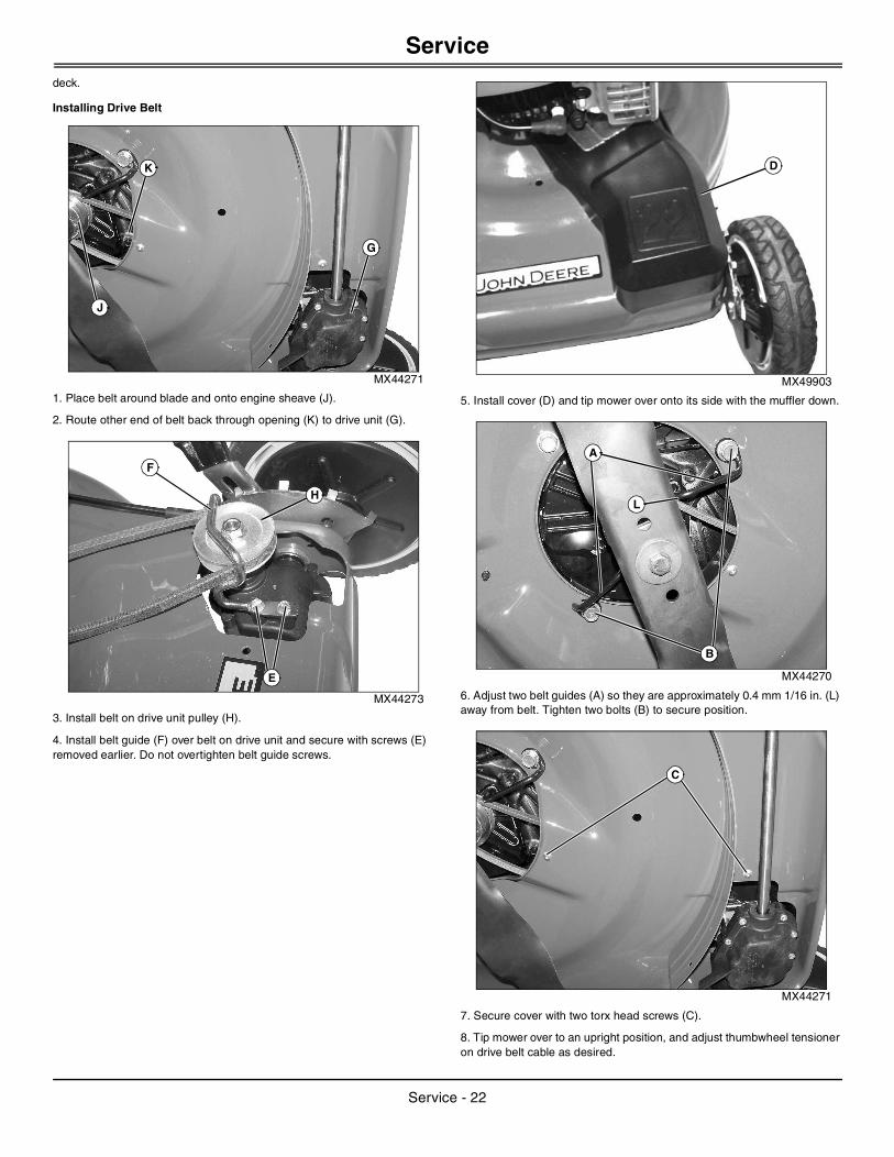
deck.Installing Drive Belt
MX44271
1. Place belt around blade and onto engine sheave (J).
2. Route other end of belt back through opening (K) to drive unit (G).
MX44273
3. Install belt on drive unit pulley (H).
4. Install belt guide (F) over belt on drive unit and secure with screws (E) removed earlier. Do not overtighten belt guide screws.
MX49903
5. Install cover (D) and tip mower over onto its side with the muffler down.
MX44270
6. Adjust two belt guides (A) so they are approximately 0.4 mm 1/16 in. (L) away from belt. Tighten two bolts (B) to secure position.
MX44271
7. Secure cover with two torx head screws (C).
8. Tip mower over to an upright position, and adjust thumbwheel tensioner on drive belt cable as desired.
J
K
G
E
F
H
D
B
A
L
C
Service - 22
Service
Replacing Drive Belt (JS38, JS48)
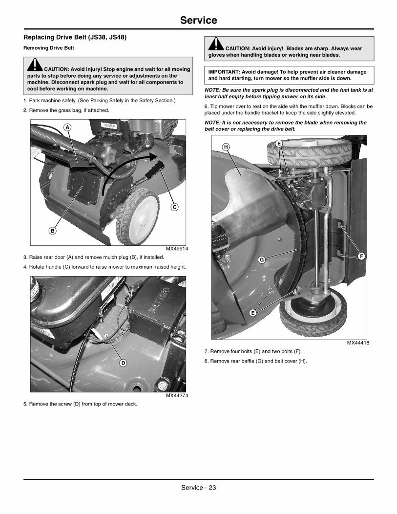
Removing Drive Belt
1. Park machine safely. (See Parking Safely in the Safety Section.)
2. Remove the grass bag, if attached.
MX49914
3. Raise rear door (A) and remove mulch plug (B), if installed.
4. Rotate handle (C) forward to raise mower to maximum raised height.
MX44274
5. Remove the screw (D) from top of mower deck.
NOTE: Be sure the spark plug is disconnected and the fuel tank is at least half empty before tipping mower on its side.
6. Tip mower over to rest on the side with the muffler down. Blocks can be placed under the handle bracket to keep the side slightly elevated.
NOTE: It is not necessary to remove the blade when removing the belt cover or replacing the drive belt.
MX44418
7. Remove four bolts (E) and two bolts (F).
8. Remove rear baffle (G) and belt cover (H).
c CAUTION: Avoid injury! Stop engine and wait for all moving parts to stop before doing any service or adjustments on the machine. Disconnect spark plug and wait for all components to cool before working on machine.
B
C
A
D
c CAUTION: Avoid injury! Blades are sharp. Always wear gloves when handling blades or working near blades.
IMPORTANT: Avoid damage! To help prevent air cleaner damage and hard starting, turn mower so the muffler side is down.
HE
E
FG
Service - 23
Service
MX44275
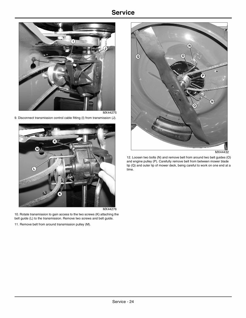
9. Disconnect transmission control cable fitting (I) from transmission (J).
MX44276
10. Rotate transmission to gain access to the two screws (K) attaching the belt guide (L) to the transmission. Remove two screws and belt guide.
11. Remove belt from around transmission pulley (M).
MX44432
12. Loosen two bolts (N) and remove belt from around two belt guides (O) and engine pulley (P). Carefully remove belt from between mower blade tip (Q) and outer lip of mower deck, being careful to work on one end at a time.
J
I
K
K
L
M
O
O
P
Q
N
N
Service - 24
Service
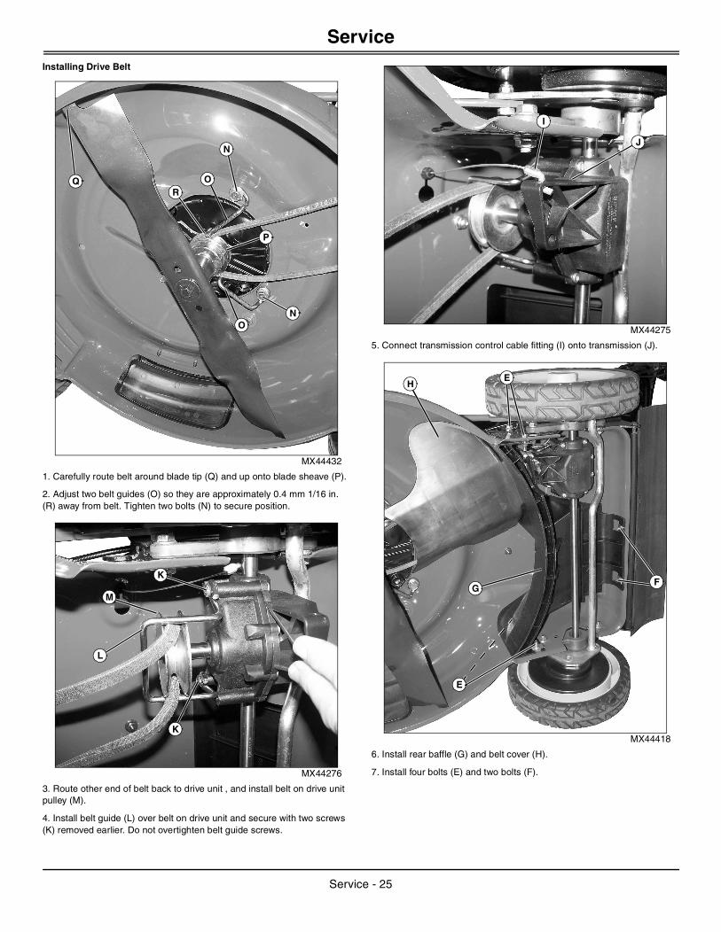
Installing Drive BeltMX44432
1. Carefully route belt around blade tip (Q) and up onto blade sheave (P).
2. Adjust two belt guides (O) so they are approximately 0.4 mm 1/16 in. (R) away from belt. Tighten two bolts (N) to secure position.
MX44276
3. Route other end of belt back to drive unit , and install belt on drive unit pulley (M).
4. Install belt guide (L) over belt on drive unit and secure with two screws (K) removed earlier. Do not overtighten belt guide screws.
MX44275
5. Connect transmission control cable fitting (I) onto transmission (J).
MX44418
6. Install rear baffle (G) and belt cover (H).
7. Install four bolts (E) and two bolts (F).
O
O
P
Q
N
N
R
K
K
L
M
J
I
HE
E
FG
Service - 25

Service
MX44274
8. Tip mower over to an upright position and install screw (D) to secure belt cover.
MX44280
9. Adjust thumbwheel tensioner (S) on drive belt cable clockwise or counterclockwise so that 1/2 in. of threads (T) are exposed past the top end of the adjuster block.
MX49914
10. If previously installed, raise rear door (A) and install mulch plug (B).
11. Rotate handle (C) rearward to lower mower to desired mowing height.
Replacing Fuses
1. Park machine safely. (See Parking Safely in the Safety Section.)
MX28034
2. Remove screw (A) and battery box cover (B).
MX28035
3. Remove fuse cover (C) and replace fuse.
4. Replace fuse cover.
5. Install battery box cover with screw.
Grease
Use a general all-purpose grease with an NLGI grade No.2 rating.
Wet or high speed conditions may require use of a special-use grease. Contact your Servicing dealer for information.
D
T
S
B
C
AIMPORTANT: Avoid damage! The recommended grease is effective within an average air temperature range of -29 to 135 degrees C (-20 to 275 degrees F).
If operating outside that temperature range, contact your servicing dealer for a special-use grease.
A
B
C
Service - 26

Service
Servicing Mower Blade
Removing and Installing Mower Blade (Early Style)
1. Park machine safely. (See Parking Safely in the Safety Section.)
NOTE: Be sure spark plug is disconnected and fuel tank is empty before tipping mower on its side to prevent fuel from entering carbon canister.
2. Turn mower onto the side toward the muffler.
MX44269
3. Remove bolt (A), washer (B) and blade (C).
4. Inspect blade; sharpen, balance or replace blade as necessary.
NOTE: Sharpened edges on blade tips must face upward when installing blade.
5. Lubricate bolt threads lightly with a general purpose grease or oil to prevent rusting and seizing.
MX22481
6. Install blade so that blade hub (D) fits between blade flanges (E).
7. Install washer (B) and bolt (A). Make sure washer is installed with cup side to the blade.
8. Tighten bolt to 54 N•m (40 lb-ft).
Removing and Installing Mower Blade (Late Style)
1. Park machine safely. (See Parking Safely in the Safety Section.)
NOTE: Be sure spark plug is disconnected and fuel tank is empty before tipping mower on its side to prevent fuel from entering carbon canister.
2. Turn mower onto the side toward the muffler.
MX49901
3. Remove bolt (A), washer (B) and blade (C).
4. Inspect blade; sharpen, balance or replace blade as necessary.
NOTE: Sharpened edges on blade tips must face upward when installing blade.
5. Lubricate bolt threads lightly with a general purpose grease or oil to prevent rusting and seizing.
MX49912
6. Install blade so that two holes (D) in blade fit onto pins on blade hub (E).
7. Install washer (B) and bolt (A). Make sure washer is installed with cup side to the blade.
8. Tighten bolt to 54 N•m (40 lb-ft).
c CAUTION: Avoid injury! Rotating blades are dangerous. Before adjusting or servicing mower:
• Disconnect spark plug wire and battery negative (-) cable to prevent engine from starting accidently.
• Always wear gloves when handling mower blades or working near blades.
IMPORTANT: Avoid damage! To help prevent air cleaner damage and hard starting, turn mower so the muffler side is down.
A
C
B
D
E
A
B
IMPORTANT: Avoid damage! To help prevent air cleaner damage and hard starting, turn mower so the muffler side is down.
B
A
C
E
A
B
D
Service - 27

Service
Sharpening Blades
• Sharpen blades with grinder, hand file, or electric blade sharpener.
MIF
• Keep original bevel (A) when grinding.
• Blade should have 0.40 mm (1/64 in.) cutting edge (B) or less.
• Balance blades before installing.
Balancing Blades
1. Clean blade.
M61524
2. Put blade on nail in a vise. Turn blade to horizontal position.
3. Check balance. If blade is not balanced, heavy end of blade will drop.
4. Grind bevel of heavy end. Do not change blade bevel.
Inserting Fuel Stabilizer Cartridge in Fresh Start™ Fuel Cap
NOTE: Your machine may be equipped with a Fresh Start fuel cap that requires a fuel stabilizer cartridge. If equipped, check periodically and replace cartridge when empty.
MX22483
1. Remove Fresh Start fuel cap (A) from fuel tank.
2. Place silver foil seal end of cartridge (B) into opening (C) on bottom side of fuel cap.
3. Press to snap cartridge into place.
4. Remove the white tab to expose membrane (D).
5. Install the fuel cap on fuel tank.
Using Proper FuelUse regular grade unleaded fuel with an octane rating of 87 octane or higher. Fuel blends containing up to 10% ethanol or up to 15% MTBE reformulated fuel are acceptable. Do not use fuel or additives containing methanol as engine damage can occur.
Always use fresh, clean fuel that is purchased in a quantity that can be used within approximately 30 days, or add fuel stabilizer.
Fuel is blended to give best seasonal performance. To avoid engine performance problems such as hard starting or vapor lock, use in-season fuel. Use fuel during warm weather that was purchased during that season, and use fuel during cold weather that was purchased during that season.
Fuel can become stale in machines with engines that are used seasonally or infrequently during a season. Stale fuel can produce varnish and plug carburetor components which can affect engine performance.
Keep fuel storage container tightly covered and in a cool area out of direct sunlight. Fuel can break down and degrade if not sealed properly or exposed to sun and heat.
Condensation may collect in the fuel tank because of a variety of operating or environmental conditions and, over time, may affect your machine’s operation. Fill fuel tank at the end of daily use and store fuel in plastic containers to reduce condensation.
For best year-round performance and fuel-handling, add stabilizer to fuel immediately after fuel purchase. Such practice helps prevent engine performance problems and allows fuel storage in the machine all year
c CAUTION: Avoid injury! Blades are sharp. Always wear gloves when handling blades or working near blades.
Always wear safety eye protection when grinding.
c CAUTION: Avoid injury! Blades are sharp. Always wear gloves when handling blades or working near blades.
A
B
c CAUTION: Avoid injury! Fuel stabilizer is a hazardous chemical and can be harmful or fatal if swallowed. Do not take internally. Avoid contact with eyes. Avoid breathing the chemical vapors.
Read safety instructions on stabilizer container label before using.
Fuel stabilizer contains 2,6-di-tert-butylphenol (128-39-2) and aliphatic petroleum distillate (64742-47-8). In case of emergency, contact a physician immediately and call 1-800-424-9300 for material safety information.
A
BCD
A
Service - 28

Service
without draining.Filling Fuel Tank
NOTE: Be sure the spark plug is disconnected and the fuel tank is at least half empty if you intend to tip mower on its side.
Fill fuel tank at the end of each day’s operation to prevent condensation and freezing during cold weather.
1. Park machine safely. (See Parking Safely in the SAFETY section.)
2. Allow engine to cool.
3. Remove any trash from area around fuel tank cap.
4. Remove fuel tank cap slowly to allow any pressure built up in tank to escape.
5. Fill fuel tank only to bottom of filler neck. Do not overfill.
6. Install fuel tank cap.
• Gas models: Turn cap until clicks.
Servicing Battery (JS48 Only)
WARNING: Battery posts, terminals and related accessories contain lead and lead components, chemicals known to the State of California to cause cancer and reproductive harm. Wash hands after handling.
Service the Battery Safely
Removing Battery
1. Park machine safely. (See Parking Safely in the Safety Section.)
MX28034
2. Remove screw (A) and battery box cover (B).
MX28035
3. Disconnect black negative battery cable connector (C).
c CAUTION: Avoid injury! Fuel vapors are explosive and flammable:
• Shut engine off before filling fuel tank.
• Allow engine to cool before refueling.
• Do not smoke while handling fuel.
• Keep fuel away from flames or sparks.
• Fill fuel tank outdoors or in well ventilated area.
• Clean up spilled fuel immediately.
• Use clean approved non-metal container to prevent static electric discharge.
IMPORTANT: Avoid damage! Dirt and water in fuel can cause engine damage:
• Clean dirt and debris from the fuel tank opening.
• Use clean, fresh, stabilized fuel.
• Fill the fuel tank at the end of each day’s operation to keep condensation out of the fuel tank.
• Use a non-metallic funnel with a plastic mesh strainer when filling the fuel tank or container.
c CAUTION: Avoid injury! The battery produces a flammable and explosive gas. The battery may explode:
• Do not smoke or have open flame near battery.
• Wear eye protection and gloves.
• Do not allow direct metal contact across battery posts.
• Remove negative cable first when disconnecting.
• Install negative cable last when connecting.
A
B
C
D
Service - 29

Troubleshooting
4. Disconnect red positive battery cable connector (D).5. Lift battery out of battery box.
Installing Battery
1. Set battery in battery box with terminals to the front.
2. Install red positive battery cable connector (D) with hardware removed earlier.
3. Install black negative battery cable connector (C) with hardware removed earlier.
4. Install battery cover and secure with screw.
Charging Battery with Supplied DC Charger
MX28302
1. Plug charger wiring connector (A) into battery connector.
2. Plug charger into 110V house wall outlet and charge battery for 48 hours. Charging battery for longer periods of time will not damage battery.
TroubleshootingUsing Troubleshooting ChartIf you are experiencing a problem that is not listed in this chart, see your authorized dealer for service.
When you have checked all the possible causes listed and you are still experiencing the problem, see your authorized dealer.
StorageStoring Safety
IMPORTANT: Avoid damage! Use the supplied DC charger that comes with your mower to charge battery. Do not use any other type of battery charger.
IF CHECK
Engine Will Not Start Fuel tank is empty.
Disconnected or dirty spark plug.
Battery dead (JS48).
Stale or dirty fuel.
Excess oil in engine or air cleaner filter saturated with oil.
A
Engine Starts Hard, Loses Power, or Runs Rough
Stale or dirty fuel.
Dirty air cleaner components.
Dirty spark plug.
Engine speed needs adjusting - See your John Deere Dealer.
Engine Stalls Cold engine.
Cutting height too low.
Mowing too fast.
Engine Vibrates Loose blade bolt.
Blade bent or not balanced.
Drive belt loose or frayed.
Mower Mows Unevenly Height adjusters are not even (JS28).
Mowing pattern not changed.
Blade dull, bent, or not balanced.
Ground speed too fast for conditions.
Discharge Chute Plugs Grass not dry.
Cutting height not raised high enough.
Dirty or full grass bag.
Mowing too fast.
Mower Jerks or Will Not Move
Drive belt broken.
Transmission/wheel drive out of adjustment.
Neutral lock is locked.
Mulched Grass Clumps or Rough
Grass not dry.
Mowing too fast.
Blade dull.
Cutting height set too low.
Slow Maximum Ground Speed
Adjust drive cable using thumbwheel adjuster to increase ground speed.
c CAUTION: Avoid injury! Fuel vapors are explosive and flammable. Engine exhaust fumes contain carbon monoxide and can cause serious illness or death:
• Run the engine only long enough to move the machine to or from storage.
• Machine fires and structure fires can occur if a machine is stored before allowing it to cool, or if debris is not removed from around the engine and muffler, or if stored near combustible materials.
• Do not store vehicle with fuel in the tank inside a building where fumes may reach an open flame or spark.
• Allow the engine to cool before storing the machine in any enclosure.
IF CHECK
Troubleshooting - 30
Specifications
Preparing Machine for Storage
1. Repair any worn or damaged parts. Replace parts if necessary. Tighten loose hardware.
2. Remove belt shield. Clean belt and transmission area. Do not use water to clean this area. Install shield.
3. Clean under the deck.
4. Sharpen mower blade.
5. Paint scratched or chipped metal surfaces to prevent rust.
6. Apply light coat of engine oil to pivot and wear points to prevent rust.
7. Lubricate grease points.
Preparing Fuel and Engine For Storage
Fuel:
If you have been using “Stabilized Fuel,” add stabilized fuel to tank until the tank is full.
NOTE: Filling the fuel tank reduces the amount of air in the fuel tank and helps reduce deterioration of fuel.
If you are not using “Stabilized Fuel” follow Inserting Fuel Stabilizer Cartridge in Fresh Start Fuel Cap instructions in this manual, or follow the instructions below to use stabilizer.
1. Park machine safely in a well-ventilated area. (See Parking Safely in the SAFETY section.)
NOTE: Try to anticipate the last time the machine will be used for the season so very little fuel is left in the fuel tank.
2. Turn on engine and allow to run until it runs out of fuel.
3. For machines equipped with a key switch, turn key to off position.
4. Mix fresh fuel and fuel stabilizer in separate container. Follow stabilizer instructions for mixing.
5. Fill fuel tank with stabilized fuel and run engine for a few minutes to allow fuel mixture to circulate through carburetor.
Engine:
Engine storage procedure should be used when vehicle is not to be used for longer than 60 days.
1. Change engine oil and filter while engine is warm.
2. Service air filter if necessary.
3. Clean debris from engine air intake screen.
4. On gas engines:
• Remove spark plugs. Put 30 mL (1 oz.) of clean engine oil in cylinders.
• Install spark plugs, but do not connect spark plug wires.
• Crank the engine five or six times to allow oil to be distributed.
5. Clean the engine and engine compartment.
6. Close fuel shut-off valve, if your machine is equipped.
7. Store the machine in a dry, protected place. If machine is stored outside, put a waterproof cover over it.
Folding Handles
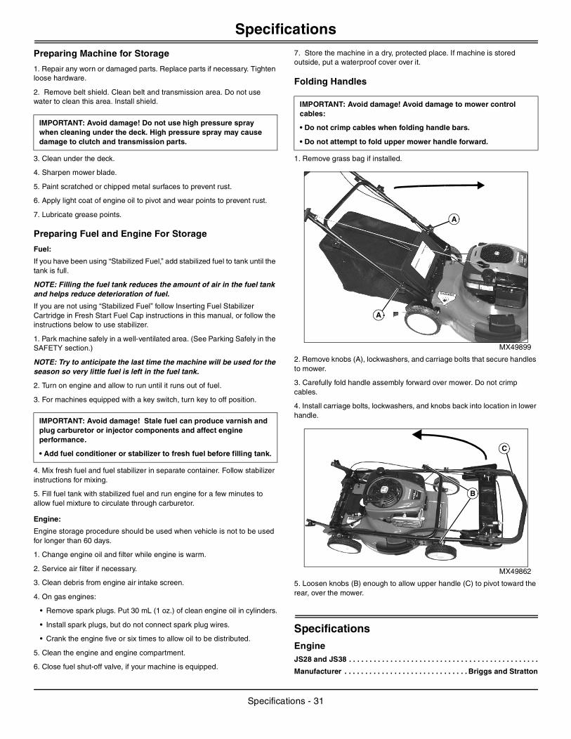
1. Remove grass bag if installed.
MX49899
2. Remove knobs (A), lockwashers, and carriage bolts that secure handles to mower.
3. Carefully fold handle assembly forward over mower. Do not crimp cables.
4. Install carriage bolts, lockwashers, and knobs back into location in lower handle.
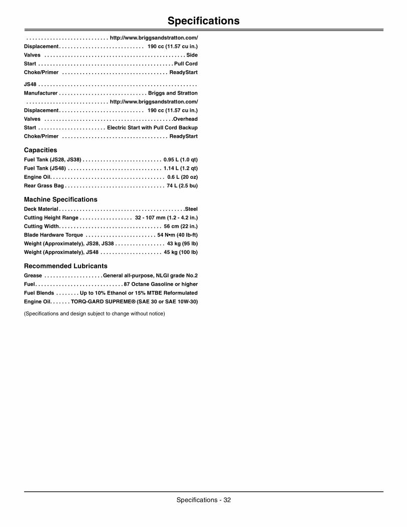
MX49862
5. Loosen knobs (B) enough to allow upper handle (C) to pivot toward the rear, over the mower.
SpecificationsEngineJS28 and JS38 . . . . . . . . . . . . . . . . . . . . . . . . . . . . . . . . . . . . . . . . . . . . . .
Manufacturer . . . . . . . . . . . . . . . . . . . . . . . . . . . . . . Briggs and Stratton
IMPORTANT: Avoid damage! Do not use high pressure spray when cleaning under the deck. High pressure spray may cause damage to clutch and transmission parts.
IMPORTANT: Avoid damage! Stale fuel can produce varnish and plug carburetor or injector components and affect engine performance.
• Add fuel conditioner or stabilizer to fresh fuel before filling tank.
IMPORTANT: Avoid damage! Avoid damage to mower control cables:
• Do not crimp cables when folding handle bars.
• Do not attempt to fold upper mower handle forward.
A
A
C
B
Specifications - 31
Specifications
. . . . . . . . . . . . . . . . . . . . . . . . . . . . http://www.briggsandstratton.com/Displacement . . . . . . . . . . . . . . . . . . . . . . . . . . . . . 190 cc (11.57 cu in.)
Valves . . . . . . . . . . . . . . . . . . . . . . . . . . . . . . . . . . . . . . . . . . . . . . . . Side
Start . . . . . . . . . . . . . . . . . . . . . . . . . . . . . . . . . . . . . . . . . . . . . . Pull Cord
Choke/Primer . . . . . . . . . . . . . . . . . . . . . . . . . . . . . . . . . . . . ReadyStart
JS48 . . . . . . . . . . . . . . . . . . . . . . . . . . . . . . . . . . . . . . . . . . . . . . . . . . . . . .
Manufacturer . . . . . . . . . . . . . . . . . . . . . . . . . . . . . . Briggs and Stratton
. . . . . . . . . . . . . . . . . . . . . . . . . . . . http://www.briggsandstratton.com/
Displacement . . . . . . . . . . . . . . . . . . . . . . . . . . . . . 190 cc (11.57 cu in.)
Valves . . . . . . . . . . . . . . . . . . . . . . . . . . . . . . . . . . . . . . . . . . . .Overhead
Start . . . . . . . . . . . . . . . . . . . . . . . Electric Start with Pull Cord Backup
Choke/Primer . . . . . . . . . . . . . . . . . . . . . . . . . . . . . . . . . . . . ReadyStart
CapacitiesFuel Tank (JS28, JS38) . . . . . . . . . . . . . . . . . . . . . . . . . . . 0.95 L (1.0 qt)
Fuel Tank (JS48) . . . . . . . . . . . . . . . . . . . . . . . . . . . . . . . . 1.14 L (1.2 qt)
Engine Oil. . . . . . . . . . . . . . . . . . . . . . . . . . . . . . . . . . . . . . . 0.6 L (20 oz)
Rear Grass Bag . . . . . . . . . . . . . . . . . . . . . . . . . . . . . . . . . . 74 L (2.5 bu)
Machine SpecificationsDeck Material . . . . . . . . . . . . . . . . . . . . . . . . . . . . . . . . . . . . . . . . . . .Steel
Cutting Height Range . . . . . . . . . . . . . . . . . . 32 - 107 mm (1.2 - 4.2 in.)
Cutting Width. . . . . . . . . . . . . . . . . . . . . . . . . . . . . . . . . . . 56 cm (22 in.)
Blade Hardware Torque . . . . . . . . . . . . . . . . . . . . . . . . 54 N•m (40 lb-ft)
Weight (Approximately), JS28, JS38 . . . . . . . . . . . . . . . . . 43 kg (95 lb)
Weight (Approximately), JS48 . . . . . . . . . . . . . . . . . . . . . 45 kg (100 lb)
Recommended LubricantsGrease . . . . . . . . . . . . . . . . . . . . General all-purpose, NLGI grade No.2
Fuel . . . . . . . . . . . . . . . . . . . . . . . . . . . . . . 87 Octane Gasoline or higher
Fuel Blends . . . . . . . . Up to 10% Ethanol or 15% MTBE Reformulated
Engine Oil. . . . . . . TORQ-GARD SUPREME® (SAE 30 or SAE 10W-30)
(Specifications and design subject to change without notice)
Specifications - 32
Warranty
WarrantyProduct WarrantyProduct warranty is provided as part of John Deere’s support program for customers who operate and maintain their equipment as described in this manual.
Engine related warranties stated in this manual refer only to emissions-related parts and components of your engine. The complete engine warranty, less emission-related parts and components, is provided separately as the “Limited Warranty for New John Deere Equipment”.
John Deere, Federal and California Emissions Control System Warranty Statement (Small Off-Road Gas Engines)Your Warranty Rights and Obligations
California Air Resources Board (CARB), the United States Environmental Protection Agency (EPA), and John Deere are pleased to explain the emissions control system warranty on your small off-road engine and equipment. In California, 2006 and later small off-road engines and equipment must be designed, built and equipped to meet the State’s stringent anti-smog standards. (In other states, 1997 and later model year equipment engines must be designed, built and equipped to meet the U.S. EPA regulations for small non-road, spark ignition engines.) John Deere must warrant the emissions control system on your small off-road engine and equipment for the periods of time listed below provided there has been no abuse, neglect or improper maintenance of your small off-road engine and equipment.
Your emissions control system may include parts such as the carburetor, fuel hose, fuel-injection system and ignition system. Also included may be connectors and other emissions related assemblies.
Where a warrantable condition exists, John Deere will repair your small off-road engine and equipment at no cost to you including diagnosis, parts and labor.
John Deere Emissions Control System Warranty Coverage
Small off-road engines and equipment are warranted relative to emissions control parts for two years. If any emissions related part on your engine or equipment is defective, the part will be repaired or replaced by John Deere.
Owner’s Warranty Responsibilities
As the small off-road engine and equipment owner, you are responsible for the performance of the required maintenance listed in your owner’s manual. John Deere recommends that you retain all receipts covering maintenance on your small off-road engine and equipment, but John Deere cannot deny warranty solely for lack of receipts or for your failure to ensure all scheduled maintenance is performed.
As the small off-road engine and equipment owner, you should however be aware that John Deere may deny you warranty coverage if your small off-road engine and equipment or a part has failed due to abuse, neglect, improper maintenance or unapproved modifications.
You are responsible for presenting your small off-road engine and equipment to an authorized John Deere Commercial and Consumer Equipment Retailer as soon as a problem exists. The warranty repairs should be completed in a reasonable amount of time, not to exceed 30 days.
If you have any questions regarding your warranty rights and responsibilities, you should contact your John Deere Commercial and Consumer Equipment Retailer, or the John Deere Customer Contact Center at 1-800-537-8233.
Length Of Warranty Coverage
John Deere warrants to the initial owner and each subsequent purchaser that the small off-road engine and equipment is:
• Designed, built and equipped so as to conform with all applicable regulations adopted by the California Air Resources Board (CARB) for 2006 and later engines and equipment, if labeled as such, and all applicable regulations of the United States Environmental Protection Agency (EPA) for 1997 and later equipment engines; and
• Free from defects in materials and workmanship which can cause the failure of an emissions warranted part for a period of two years after the engine and equipment is delivered to the initial retail purchaser. John Deere is liable for damages to other engine components caused by the failure of a warranted part during the warranty period. If any emissions related part on your engine or equipment is defective, the part will be repaired or replaced by John Deere.
Warranted Parts
Coverage under this warranty extends only to the parts listed below (the emissions control system parts) to the extent these parts were present on the engine and equipment purchased.
Fuel Metering System:
• Carburetor and internal parts (or fuel injection system).
• Air/fuel ratio feedback and control system.
• Cold start enrichment system.
Evaporative System:
• Fuel tank, fuel cap and tether.
• Fuel hose, line, fittings, clamps.
• Fuel pump, fuel shut-off valve.
• Fuel vapor hoses, fittings.
• Carbon canister.
• Rollover/slant valve for fuel vapor control.
Air Induction System:
• Air cleaner
• Intake manifold.
Ignition System:
• Spark plugs.
• Magneto or electronic ignition system.
• Spark advance/retard system.
Exhaust System:
• Exhaust manifold.
• Catalyst muffler.
Miscellaneous Items Used in Above Systems
• Vacuum and temperature switches.
• Electronic controls.
• Hoses, belts, connectors and assemblies.
Since emissions related parts may vary slightly from model to model, certain models may not contain all of these parts and certain models may contain functionally equivalent parts.
Warranty Service And Charges
Warranty service shall be provided during customary business hours at any authorized John Deere Commercial and Consumer Equipment Retailer. Repair or replacement of any warranted part will be performed at no charge to the owner, including diagnostic labor which leads to the determination that a warranted part is defective, if the diagnostic work is performed at an authorized John Deere Commercial and Consumer Equipment Retailer. Any parts replaced under this warranty shall become
Warranty - 33

Warranty
the property of John Deere.Maintenance Warranty Coverage
a) Any warranted part that is not scheduled for replacement as required maintenance is warranted as to defects for the warranty period. Any such part repaired or replaced under the warranty is warranted for the remaining warranty period.
b) Any warranted part that is scheduled only for regular inspection to the effect of “repair or replace as necessary” is warranted as to defects for the warranty period. Any such part repaired or replaced under the warranty is warranted for the remaining warranty period.
c) Any warranted part which is scheduled for replacement as required maintenance is warranted as to defects only for the period of time up to the first scheduled replacement for that part. Any such part repaired or replaced under the warranty is warranted for the remainder of the period prior to the first scheduled replacement point for that part.
d) Normal maintenance, replacement or repair of emissions control devices and systems, which are being done at the customer’s expense, may be performed by any repair establishment or individual; however, warranty repairs must be performed by an authorized John Deere Commercial and Consumer Equipment Retailer.
e) Any replacement part that is equivalent in performance and durability may be used in the performance of any non-warranty maintenance or repairs, and shall not reduce the warranty obligations of John Deere.
Consequential Warranty Coverage
Warranty coverage shall extend to the failure of any engine components caused by the failure of any warranted part still under warranty.
Limitations
This Emissions Control System Warranty shall NOT cover any of the following:
a) Repair or replacement required as a result of (i) misuse or neglect, (ii) improper maintenance or unapproved modifications, (iii) repairs improperly performed or replacements improperly installed, (iv) use of replacement parts or accessories not conforming to John Deere specifications which adversely affect performance and/or durability, (v) alterations or modifications not recommended or approved in writing by John Deere.
b) Replacement parts, other services and adjustments necessary for normal maintenance.
c) Transportation to and from the John Deere Commercial and Consumer Equipment Retailer, or service calls made by the Retailer.
Limited Liability
a) The liability of John Deere under this Emissions Control System Warranty is limited solely to the remedying of defects in materials or workmanship. This warranty does not cover inconvenience or loss of use of the small off-road engine and equipment or transportation of the equipment to or from the John Deere Commercial and Consumer Equipment Retailer. JOHN DEERE SHALL NOT BE LIABLE FOR ANY OTHER EXPENSE, LOSS, OR DAMAGE, WHETHER DIRECT, INCIDENTAL, CONSEQUENTIAL (EXCEPT AS LISTED ABOVE UNDER “COVERAGE”) OR EXEMPLARY ARISING IN CONNECTION WITH THE SALE OR USE OF OR INABILITY TO USE THE SMALL OFF-ROAD ENGINE AND EQUIPMENT FOR ANY OTHER PURPOSE.
b) NO EXPRESS EMISSIONS CONTROL SYSTEM WARRANTY IS GIVEN BY JOHN DEERE WITH RESPECT TO THE ENGINE AND EQUIPMENT EXCEPT AS SPECIFICALLY SET FORTH IN THIS DOCUMENT. ANY EMISSIONS CONTROL SYSTEM WARRANTY IMPLIED BY LAW, INCLUDING ANY WARRANTY OF MERCHANTABILITY OR FITNESS FOR A PARTICULAR PURPOSE, IS EXPRESSLY LIMITED TO THE EMISSIONS CONTROL SYSTEM WARRANTY TERMS SET FORTH IN THIS DOCUMENT.
c) No dealer is authorized to modify this John Deere, Federal and California Emissions Control System Warranty.
Warranty - 34
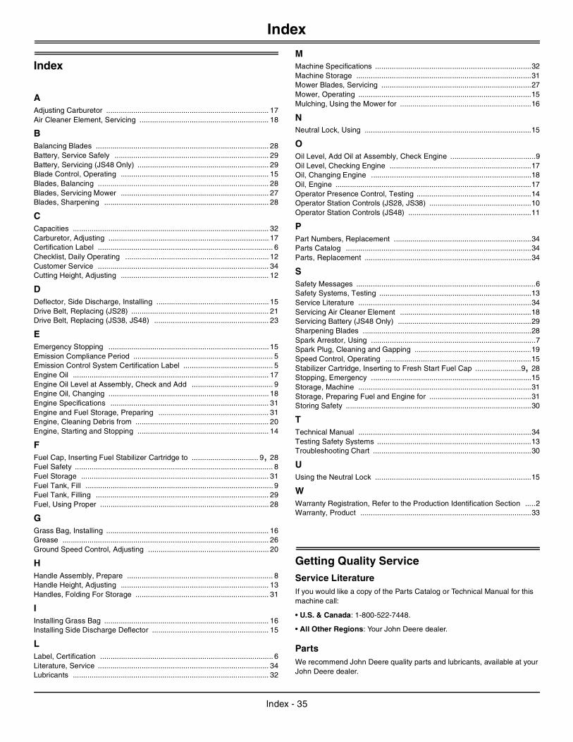
Index
Index
AAdjusting Carburetor .............................................................................. 17Air Cleaner Element, Servicing .............................................................. 18
BBalancing Blades ................................................................................... 28Battery, Service Safely .......................................................................... 29Battery, Servicing (JS48 Only) ............................................................... 29Blade Control, Operating ....................................................................... 15Blades, Balancing .................................................................................. 28Blades, Servicing Mower ....................................................................... 27Blades, Sharpening ............................................................................... 28
CCapacities .............................................................................................. 32Carburetor, Adjusting ............................................................................. 17Certification Label .................................................................................... 6Checklist, Daily Operating ..................................................................... 12Customer Service .................................................................................. 34Cutting Height, Adjusting ....................................................................... 12
DDeflector, Side Discharge, Installing ...................................................... 15Drive Belt, Replacing (JS28) .................................................................. 21Drive Belt, Replacing (JS38, JS48) ....................................................... 23
EEmergency Stopping ............................................................................. 15Emission Compliance Period ................................................................... 5Emission Control System Certification Label ........................................... 5Engine Oil .............................................................................................. 17Engine Oil Level at Assembly, Check and Add ....................................... 9Engine Oil, Changing ............................................................................. 18Engine Specifications ............................................................................ 31Engine and Fuel Storage, Preparing ..................................................... 31Engine, Cleaning Debris from ................................................................ 20Engine, Starting and Stopping ............................................................... 14
FFuel Cap, Inserting Fuel Stabilizer Cartridge to ................................ 9, 28Fuel Safety ............................................................................................... 8Fuel Storage .......................................................................................... 31Fuel Tank, Fill .......................................................................................... 9Fuel Tank, Filling ................................................................................... 29Fuel, Using Proper ................................................................................. 28
GGrass Bag, Installing .............................................................................. 16Grease ................................................................................................... 26Ground Speed Control, Adjusting .......................................................... 20
HHandle Assembly, Prepare ...................................................................... 8Handle Height, Adjusting ....................................................................... 13Handles, Folding For Storage ................................................................ 31
IInstalling Grass Bag ............................................................................... 16Installing Side Discharge Deflector ........................................................ 15
LLabel, Certification ................................................................................... 6Literature, Service .................................................................................. 34Lubricants .............................................................................................. 32
MMachine Specifications ...........................................................................32Machine Storage ....................................................................................31Mower Blades, Servicing ........................................................................27Mower, Operating ...................................................................................15Mulching, Using the Mower for ...............................................................16
NNeutral Lock, Using ................................................................................15
OOil Level, Add Oil at Assembly, Check Engine .........................................9Oil Level, Checking Engine ....................................................................17Oil, Changing Engine .............................................................................18Oil, Engine ..............................................................................................17Operator Presence Control, Testing .......................................................14Operator Station Controls (JS28, JS38) .................................................10Operator Station Controls (JS48) ...........................................................11
PPart Numbers, Replacement ..................................................................34Parts Catalog .........................................................................................34Parts, Replacement ................................................................................34
SSafety Messages ......................................................................................6Safety Systems, Testing .........................................................................13Service Literature ...................................................................................34Servicing Air Cleaner Element ...............................................................18Servicing Battery (JS48 Only) ................................................................29Sharpening Blades .................................................................................28Spark Arrestor, Using ...............................................................................7Spark Plug, Cleaning and Gapping ........................................................19Speed Control, Operating ......................................................................15Stabilizer Cartridge, Inserting to Fresh Start Fuel Cap ......................9, 28Stopping, Emergency .............................................................................15Storage, Machine ...................................................................................31Storage, Preparing Fuel and Engine for .................................................31Storing Safety .........................................................................................30
TTechnical Manual ...................................................................................34Testing Safety Systems ..........................................................................13Troubleshooting Chart ............................................................................30
UUsing the Neutral Lock ...........................................................................15
WWarranty Registration, Refer to the Production Identification Section .....2Warranty, Product ..................................................................................33
Getting Quality ServiceService LiteratureIf you would like a copy of the Parts Catalog or Technical Manual for this machine call:
• U.S. & Canada: 1-800-522-7448.
• All Other Regions: Your John Deere dealer.
PartsWe recommend John Deere quality parts and lubricants, available at your John Deere dealer.
Index - 35
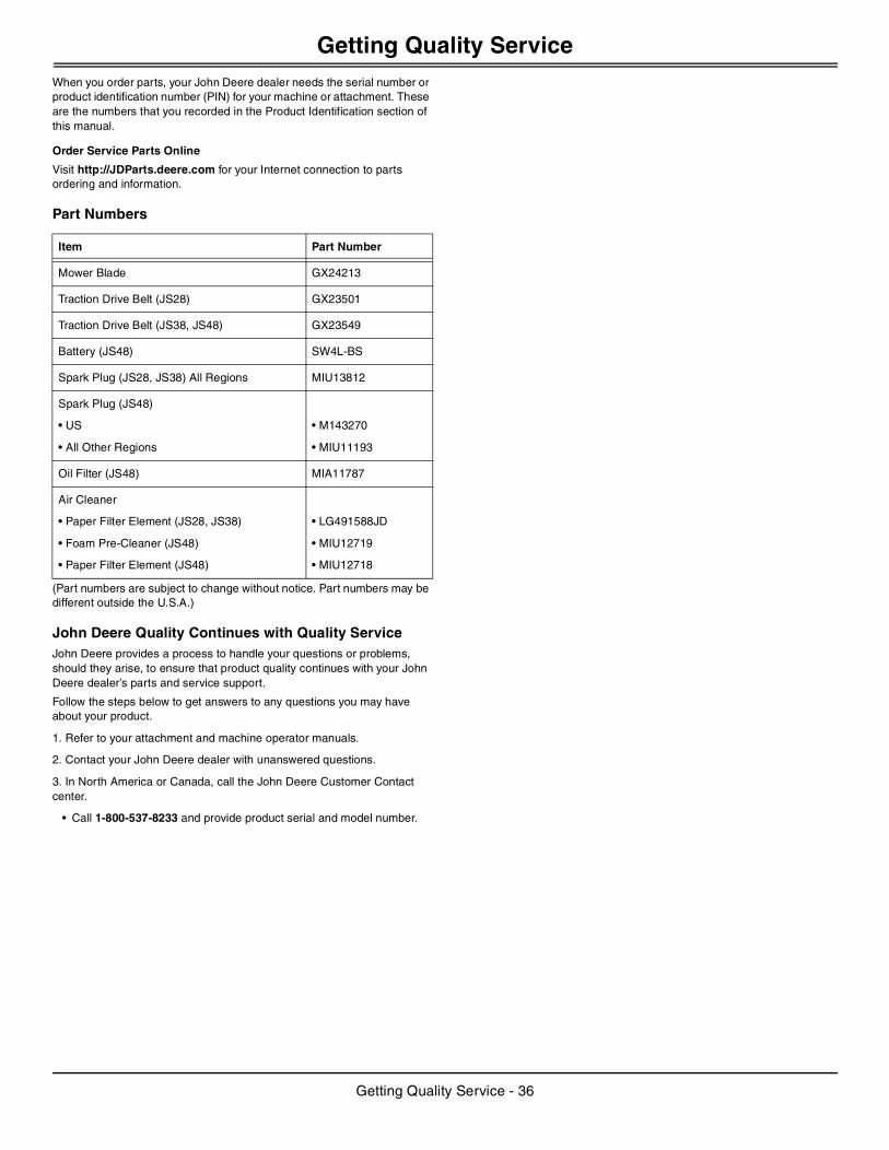
Getting Quality Service
When you order parts, your John Deere dealer needs the serial number or product identification number (PIN) for your machine or attachment. These are the numbers that you recorded in the Product Identification section of this manual.Order Service Parts Online
Visit http://JDParts.deere.com for your Internet connection to parts ordering and information.
Part Numbers
(Part numbers are subject to change without notice. Part numbers may be different outside the U.S.A.)
John Deere Quality Continues with Quality ServiceJohn Deere provides a process to handle your questions or problems, should they arise, to ensure that product quality continues with your John Deere dealer’s parts and service support.
Follow the steps below to get answers to any questions you may have about your product.
1. Refer to your attachment and machine operator manuals.
2. Contact your John Deere dealer with unanswered questions.
3. In North America or Canada, call the John Deere Customer Contact center.
• Call 1-800-537-8233 and provide product serial and model number.
Item Part Number
Mower Blade GX24213
Traction Drive Belt (JS28) GX23501
Traction Drive Belt (JS38, JS48) GX23549
Battery (JS48) SW4L-BS
Spark Plug (JS28, JS38) All Regions MIU13812
Spark Plug (JS48)
• US
• All Other Regions
• M143270
• MIU11193
Oil Filter (JS48) MIA11787
Air Cleaner
• Paper Filter Element (JS28, JS38)
• Foam Pre-Cleaner (JS48)
• Paper Filter Element (JS48)
• LG491588JD
• MIU12719
• MIU12718
Getting Quality Service - 36

Notes
NOTES

Notes
NOTES

Notes
NOTES


