5. DISPLAY AND MENU STRUCTURE .................................................................................. 50
MENU STRUCTURE ..................................................................................................................... 55 STATUS LINE TEXT ...................................................................................................................... 57 MODE OVERVIEW ....................................................................................................................... 63 PASSWORD................................................................................................................................ 63
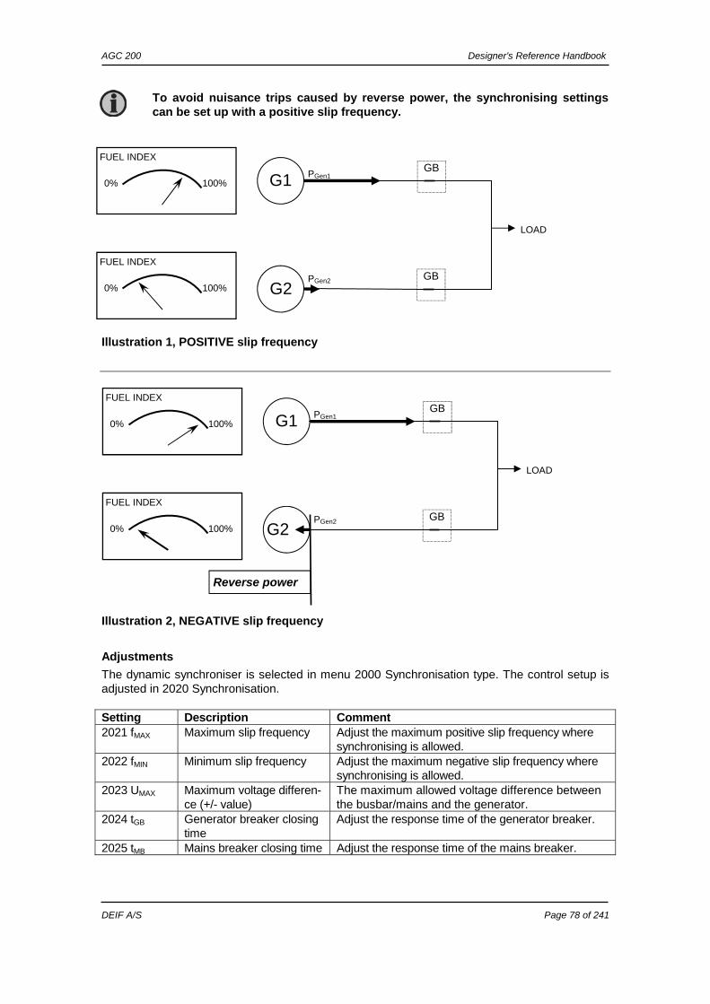
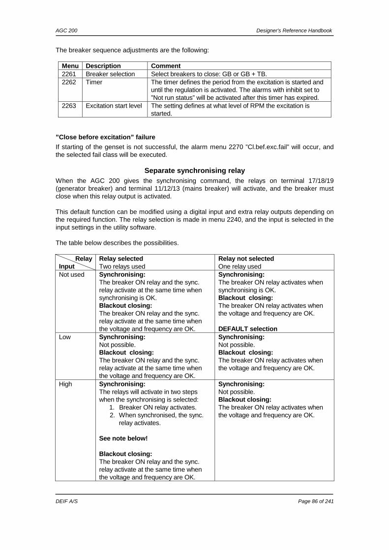
DYNAMIC SYNCHRONISATION ...................................................................................................... 76 STATIC SYNCHRONISATION ......................................................................................................... 79 GB CLOSING BEFORE EXCITATION ............................................................................................... 81 SEPARATE SYNCHRONISING RELAY ............................................................................................. 86
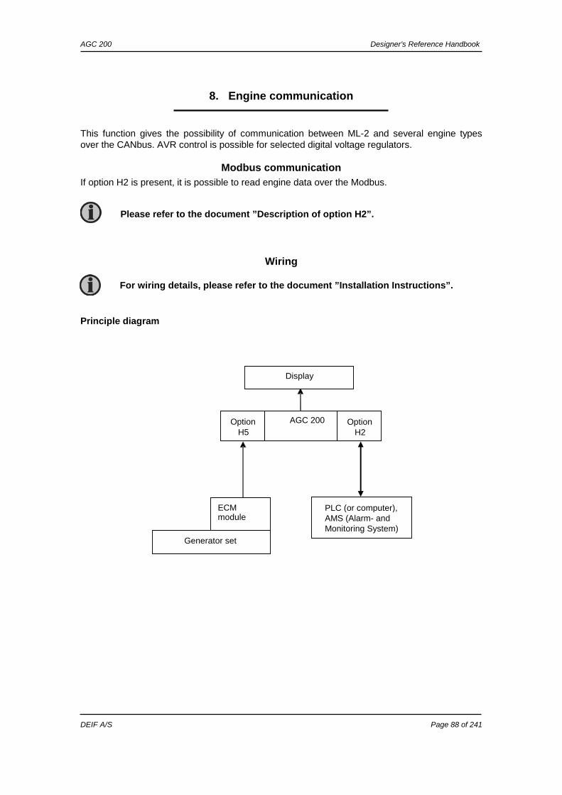
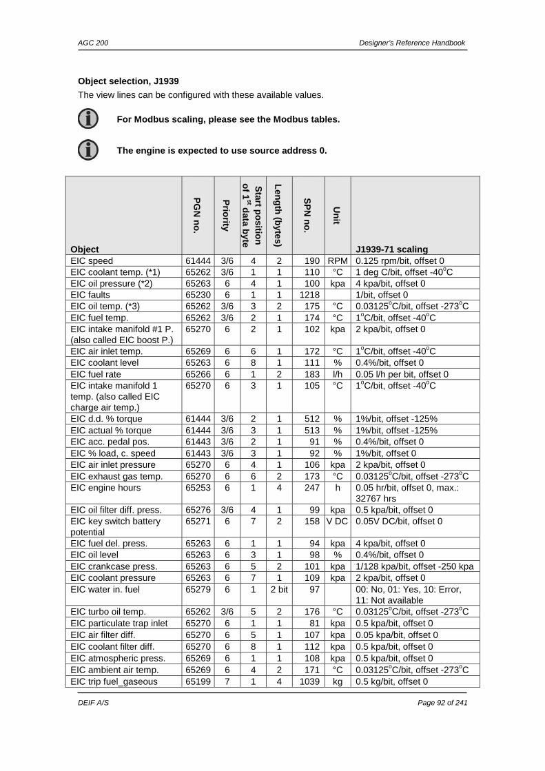
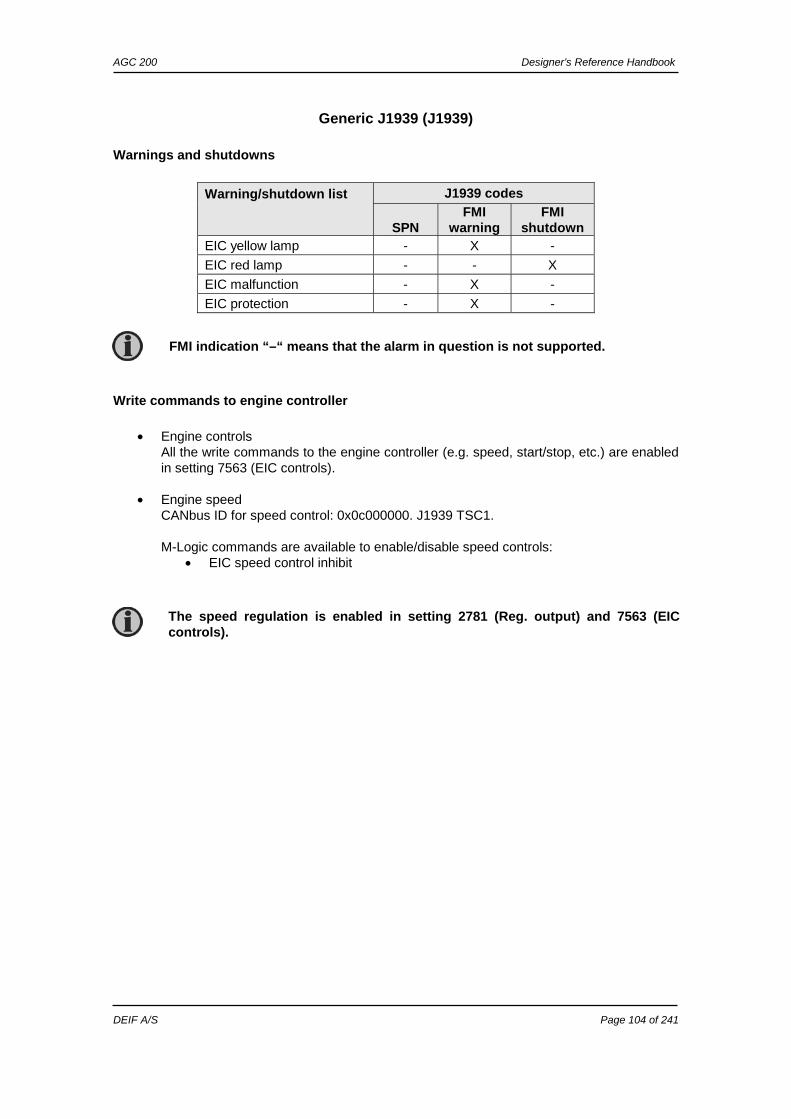
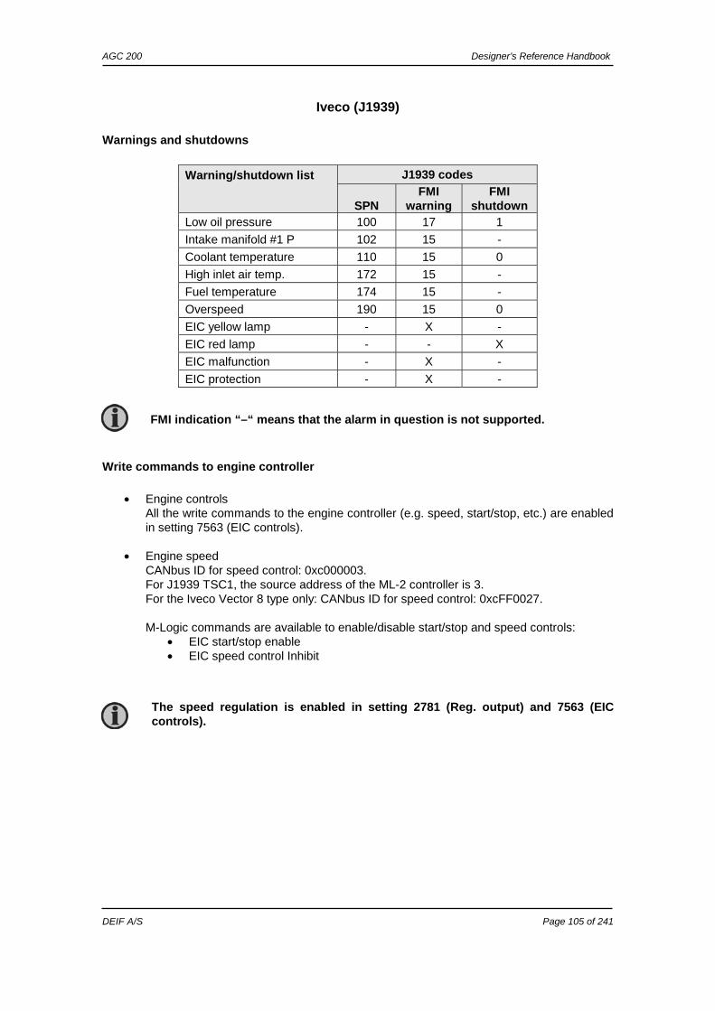
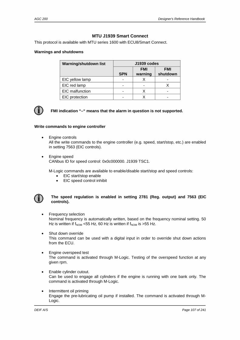
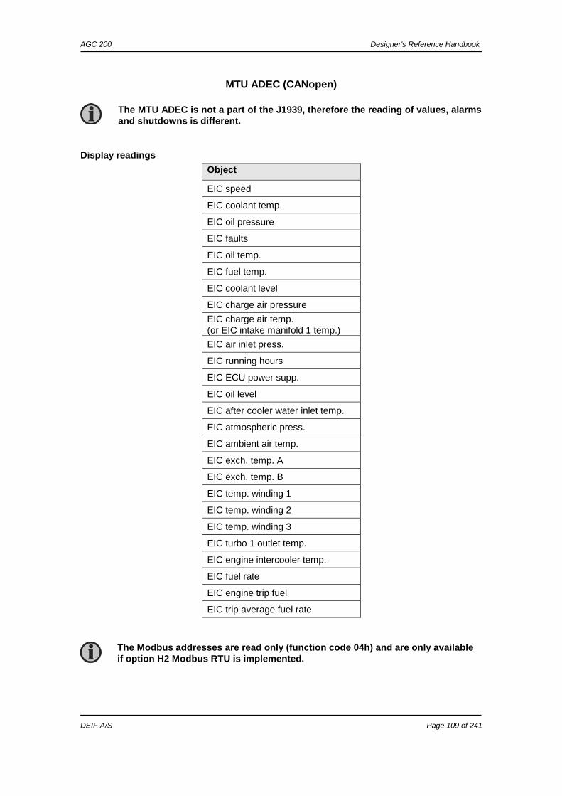
8. ENGINE COMMUNICATION ............................................................................................... 88
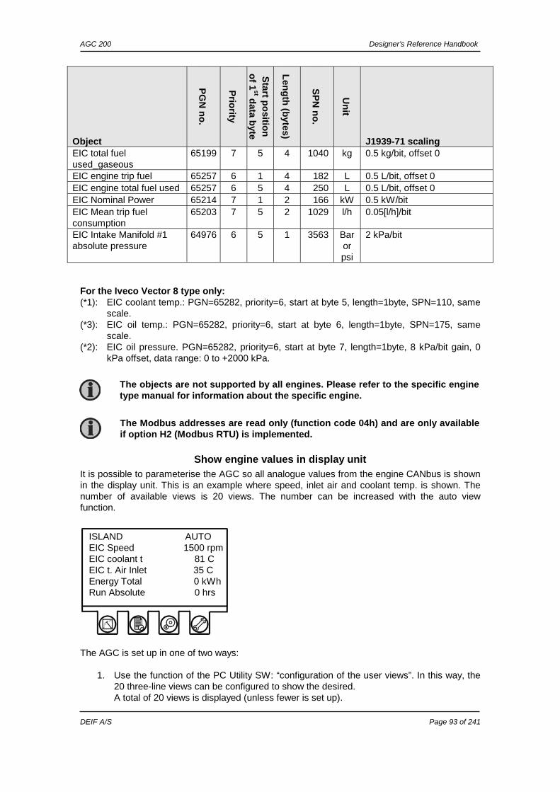
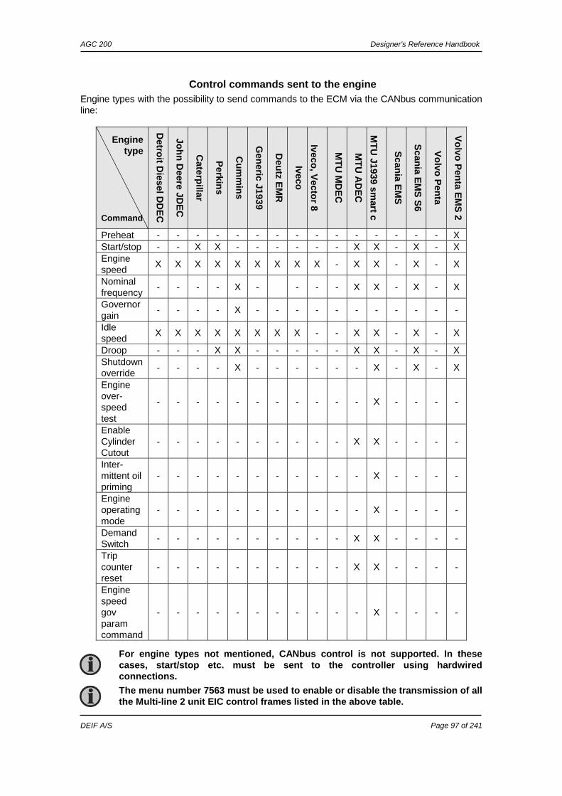
MODBUS COMMUNICATION .......................................................................................................... 88 WIRING ..................................................................................................................................... 88 FUNCTIONAL DESCRIPTION ......................................................................................................... 89 SHOW ENGINE VALUES IN DISPLAY UNIT ....................................................................................... 93 CONTROL COMMANDS SENT TO THE ENGINE ................................................................................ 97 EIC 50 HZ – 60 HZ SWITCH ........................................................................................................ 98 EIC DROOP ................................................................................................................................ 98
9. POWER MANAGEMENT (AGC 24X ONLY) ..................................................................... 133
POWER MANAGEMENT FUNCTIONS ............................................................................................ 133 APPLICATIONS ......................................................................................................................... 134 INITIAL POWER MANAGEMENT SETUP ......................................................................................... 137 REMOVE UNIT FROM PM ........................................................................................................... 140 CANBUS FAILURE HANDLING..................................................................................................... 141 QUICK SETUP ........................................................................................................................... 144 9180 QUICK SETUP .................................................................................................................. 146 COMMAND UNIT ........................................................................................................................ 148 LOAD-DEPENDENT STARTING AND STOPPING ............................................................................. 148 LOAD MANAGEMENT ................................................................................................................. 155 LOAD SHARING ......................................................................................................................... 157 ISLAND RAMP-UP WITH LOAD STEPS .......................................................................................... 158 FIXED POWER RAMP-UP WITH LOAD STEPS ................................................................................ 158 FREEZE POWER RAMP .............................................................................................................. 159 ATS APPLICATIONS .................................................................................................................. 159 FAIL CLASS .............................................................................................................................. 160 LOCAL/REMOTE/TIMER OPERATION ............................................................................................ 160 MULTI-STARTING GENSETS ....................................................................................................... 163 PRIORITY SELECTION................................................................................................................ 165 CONDITIONAL CONNECTION OF HEAVY CONSUMERS ................................................................... 169 GROUND RELAY ....................................................................................................................... 171 STOP OF NON-CONNECTED GENSETS ........................................................................................ 172 SECURED MODE ....................................................................................................................... 172 BASE LOAD .............................................................................................................................. 172
AGC 200 Designer’s Reference Handbook
DEIF A/S Page 4 of 241
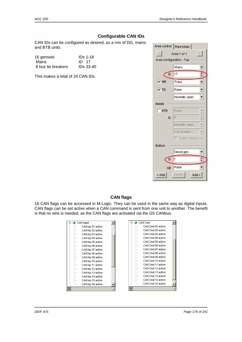
ASYMMETRIC LOAD SHARING (LS) ............................................................................................. 173 TIE BREAKER CONFIGURATION .................................................................................................. 174 ISLAND APPLICATION WITH TB .................................................................................................. 175 CONFIGURABLE CAN IDS ......................................................................................................... 176 CAN FLAGS ............................................................................................................................. 176 COMMON PF CONTROL ............................................................................................................. 177 PARAMETER LISTS, COMMON SETTINGS ..................................................................................... 178
12. PARAMETER LIST ........................................................................................................ 241
AGC 200 Designer’s Reference Handbook
DEIF A/S Page 5 of 241
1. About this document This chapter includes general user information about this handbook concerning the general purpose, the intended users and the overall contents and structure.
General purpose This document is the Designer’s Reference Handbook for DEIF’s Advanced Genset Controller, the AGC 200. The document mainly includes functional descriptions, presentation of display unit and menu structure, information about the PID controller and the procedure for parameter setup. The general purpose of the Designer’s Reference Handbook is to provide useful overall information about the functionality of the unit and its applications. This handbook also offers the user the information he needs in order to successfully set up the parameters needed in his specific application.
Intended users The handbook is mainly intended for the person responsible for the unit parameter setup. In most cases, this would be a panel builder designer. Naturally, other users might also find useful information in the handbook.
Contents/overall structure The Designer’s Reference Handbook is divided into chapters and in order to make the structure of the document simple and easy to use, each chapter will begin from the top of a new page. The following will outline the contents of each of the chapters.
About this document
This first chapter includes general information about this handbook as a document. It deals with the general purpose and the intended users of the Designer’s Reference Handbook. Furthermore, it outlines the overall contents and structure of the document.
Warnings and legal information
The second chapter includes information about general legal issues and safety precautions relevant in the handling of DEIF products. Furthermore, this chapter will introduce note and warning symbols, which will be used throughout the handbook.
General product information
The third chapter will deal with the unit in general and its place in the DEIF product range.
Functional descriptions
This chapter will include functional descriptions of the standard functions as well as illustrations of relevant application types. Flowcharts and single-line representations will be used in order to simplify the information.
Please make sure to read this handbook before working with the Multi-line 2 controller and the genset to be controlled. Failure to do this could result in human injury or damage to the equipment.
AGC 200 Designer’s Reference Handbook
DEIF A/S Page 6 of 241
Display unit and menu structure
This chapter deals with the display unit including the push-button and LED functions. In addition, the unit menu structure will be presented. Furthermore, the selection of unit mode and password will be illustrated.
PID controller
This chapter offers information about the PID controller in the form of principle drawings and descriptions.
Synchronisation
This chapter provides detailed information about the unit’s dynamic and static synchronisation.
Engine communication
This chapter provides information about the J1939 and MTU engine communication.
Power management (AGC 24X only)
This chapter provides information about the 24X series of controllers with power management.
Additional functions
This chapter describes the additional functions of the unit.
Procedure for parameter setup
This chapter deals with the procedure to be followed, when the parameters are set up or changed. By use of various illustrations this chapter will guide the user through the procedure for parameter setup step by step.
Parameter list
This chapter is a reference to the separate document ”AGC 200 Parameter List”.
AGC 200 Designer’s Reference Handbook
DEIF A/S Page 7 of 241
2. Warnings and legal information This chapter includes important information about general legal issues relevant in the handling of DEIF products. Furthermore, some overall safety precautions will be introduced and recommended. Finally, the highlighted notes and warnings, which will be used throughout this handbook, are presented.
Legal information and responsibility DEIF takes no responsibility for installation or operation of the generator set. If there is any doubt about how to install or operate the generator set controlled by the unit, the company responsible for the installation or the operation of the set must be contacted.
Electrostatic discharge awareness Sufficient care must be taken to protect the terminals against static discharges during the installation. Once the unit is installed and connected, these precautions are no longer necessary.
Safety issues Installing the unit implies work with dangerous currents and voltages. Therefore, the installation should only be carried out by authorised personnel who understand the risks involved in working with live electrical equipment.
Definitions Throughout this document a number of notes and warnings will be presented. To ensure that these are noticed, they will be highlighted in order to separate them from the general text.
Notes
Warnings
The notes provide general information which will be helpful for the reader to bear in mind.
The warnings indicate a potentially dangerous situation which could result in death, personal injury or damaged equipment, if certain guidelines are not followed.
Be aware of the hazardous live currents and voltages. Do not touch any AC measurement inputs as this could lead to injury or death.
The units are not to be opened by unauthorised personnel. If opened anyway, the warranty will be lost.
AGC 200 Designer’s Reference Handbook
DEIF A/S Page 8 of 241
3. General product information This chapter will deal with the unit in general and its place in the DEIF product range.
Introduction The AGC 200 is part of the DEIF Multi-line 2 product family. Multi-line 2 is a complete range of multi-function generator protection and control products integrating all the functions you need into one compact and attractive solution. The concept of the AGC 200 is to offer a cost-effective solution to genset builders, who need a flexible generator protection and control unit for medium to large genset applications. Being part of the Multi-line product family, the standard functions can be supplemented with a variety of optional functions.
Type of product The Advanced Genset Controller is a micro-processor based control unit containing all necessary functions for protection and control of a genset. It contains all necessary 3-phase measuring circuits, and all values and alarms are presented on the LCD display.
Options The Multi-line 2 product range consists of different basic versions which can be supplemented with the flexible options needed to provide the optimum solution. The options cover e.g. various protections for generator, busbar and mains, voltage/VAr/PF control, various outputs, power management, serial communication, additional operator display, etc.
PC utility software warning
It is possible to remote control the genset from the PC utility software or M-Vision by use of a modem. To avoid personal injury, make sure that it is safe to remote control the genset.
A full options list is included in the data sheet, document no. 4921240362. Please see www.deif.com.
AGC 200 Designer’s Reference Handbook
DEIF A/S Page 9 of 241
4. Functional descriptions This chapter includes functional descriptions of standard functions as well as illustrations of the relevant application types. Flowcharts and single-line diagrams will be used in order to simplify the information.
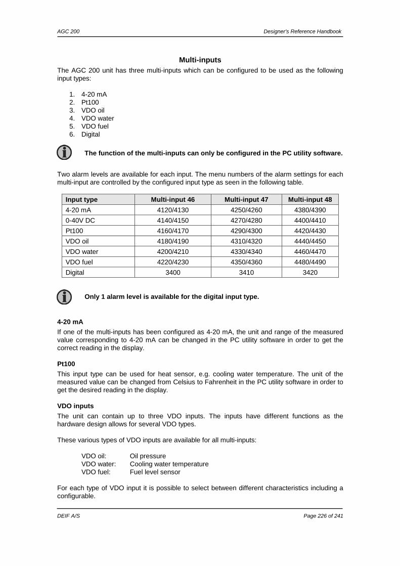
• Start/stop sequences • Run and stop coil • Relay outputs for governor control • J1939 engine communication and control • Multi-inputs (digital, 4-20 mA, Pt100 or VDO) • Digital inputs
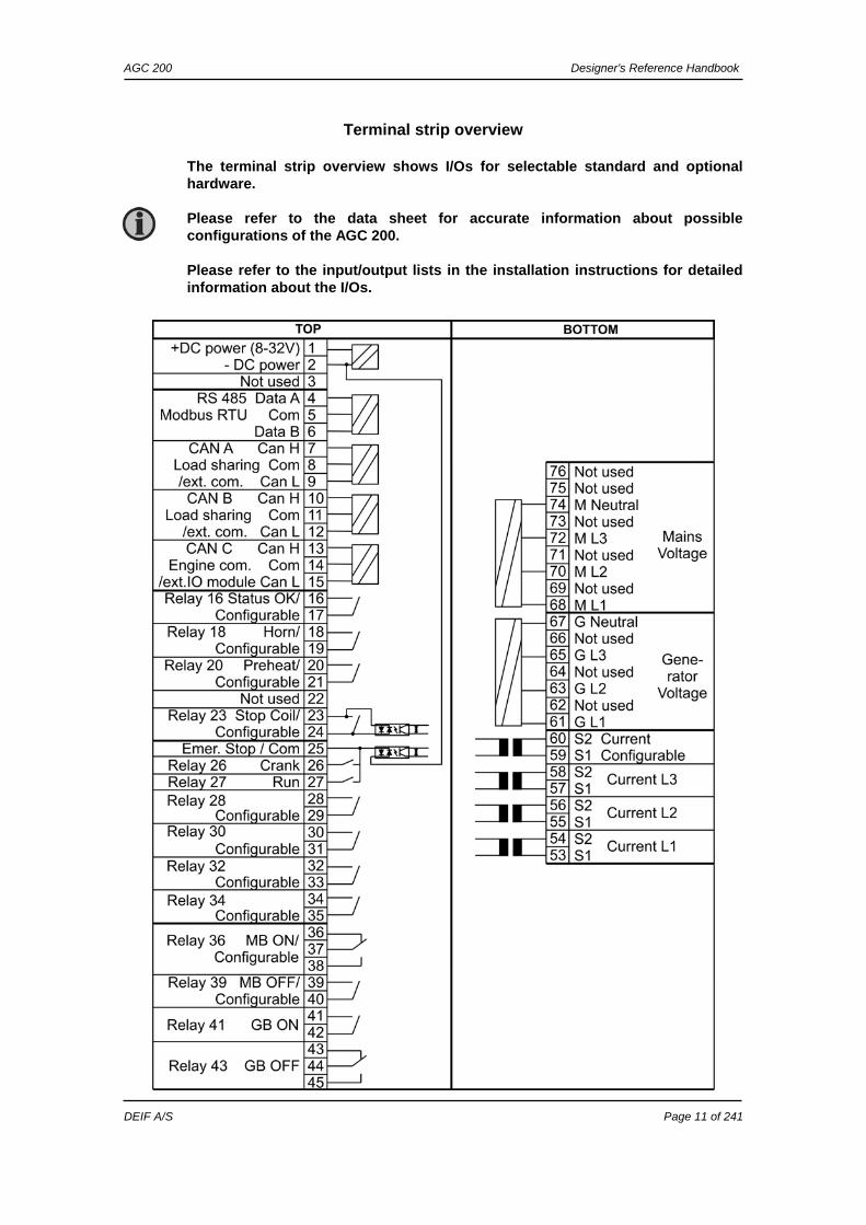
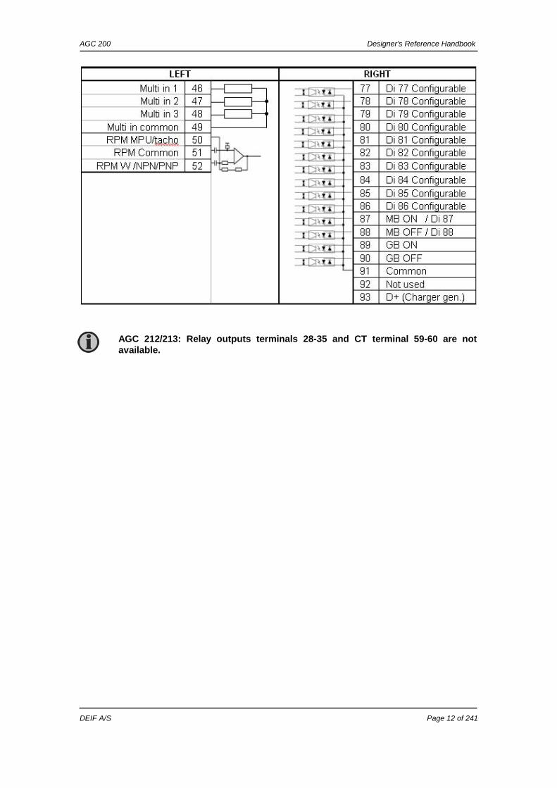
The terminal strip overview shows I/Os for selectable standard and optional hardware. Please refer to the data sheet for accurate information about possible configurations of the AGC 200. Please refer to the input/output lists in the installation instructions for detailed information about the I/Os.
AGC 200 Designer’s Reference Handbook
DEIF A/S Page 12 of 241
AGC 212/213: Relay outputs terminals 28-35 and CT terminal 59-60 are not available.
AGC 200 Designer’s Reference Handbook
DEIF A/S Page 13 of 241
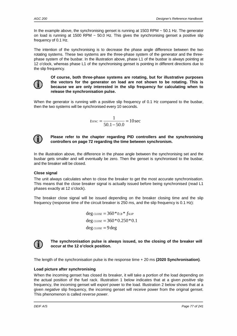
Applications The unit can be used for the applications listed in the table below. Application (single generator) Comment Automatic Mains Failure (no back sync.) Standard Automatic Mains Failure (with back sync.) Standard Island operation Standard Fixed power/base load Standard Peak shaving Standard Load takeover Standard Mains power export (fixed power to mains) Standard Application (multiple generators) Comment CANbus load sharing AGC 23x and 24x only Power management AGC 24x only Genset mode (single generator) Running mode Auto Semi Test Man Block Automatic Mains Failure (no back sync.) X X X X X Automatic Mains Failure (with back sync.) X X X X X Island operation X X X X Fixed power/base load X X X X X Peak shaving X X X X X Load takeover X X X X X Mains power export X X X X X Genset mode (multiple gensets) Running mode Auto Semi Test Man Block Load sharing X X X X Power management X X X X X
AMF (no back synchronisation)
Auto mode description
The unit automatically starts the genset and switches to generator supply at a mains failure after an adjustable delay time. It is possible to adjust the unit to change to genset operation in two different ways:
1. The mains breaker will be opened at genset start-up. 2. The mains breaker will remain closed until the genset is running and the genset voltage
and frequency is OK. In both cases, the generator breaker will be closed when the generator voltage and frequency is OK, and the mains breaker is open. When the mains returns, the unit will switch back to mains supply and cool down and stop the
For a general description of the available running modes, please refer to the chapter ”Running mode description”.
This section about applications is to be used for reference, using the particular genset mode as starting point. It is not suitable for reading from beginning to end.
AGC 200 Designer’s Reference Handbook
DEIF A/S Page 14 of 241
genset. The switching back to mains supply is done without back synchronisation when the adjusted ”Mains OK delay” has expired.
Semi-auto mode description
When the generator breaker is closed, the unit will use the nominal frequency as the setpoint for the speed governor and nominal voltage for the AVR.
AMF (with back synchronisation)
Auto mode description
The unit automatically starts the genset and switches to generator supply at a mains failure after an adjustable delay time. It is possible to adjust the unit to change to genset operation in two different ways:
1. The mains breaker will be opened at genset start-up. 2. The mains breaker will remain closed until the genset is running and the genset voltage
and frequency is OK. In both cases, the generator breaker will be closed when the generator voltage and frequency is OK, and the mains breaker is open. When the mains returns, the unit will synchronise the mains breaker to the busbar when the ”Mains OK delay” has expired. Then the genset cools down and stops.
Semi-auto mode description
When the generator breaker is closed and the mains breaker is opened, the unit will use the nominal frequency as the setpoint for the speed governor and the nominal voltage for the AVR. When the generator is paralleled to the mains, the governor regulation will no longer be active. If AVR control is selected, then the setpoint will be the adjusted power factor.
Island operation
Auto mode description
The unit automatically starts the genset and closes the generator breaker at a digital start command. When the stop command is given, the generator breaker is tripped and the genset will be stopped after a cooling-down period. The start and stop commands are used by activating and deactivating a digital input. If the time-dependent start/stop commands are to be used, then the auto mode must also be used. In this case, the digital input ”auto start/stop” cannot be used.
Semi-auto mode description
When the generator breaker is closed, the unit will use the nominal frequency as setpoint for the
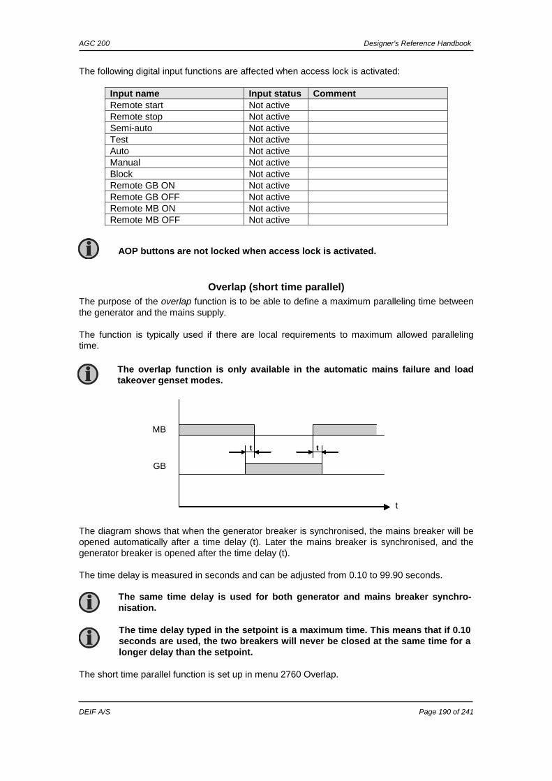
The automatic mains failure mode can be combined with the ”overlap” function. In that case, the generator breaker and the mains breaker will never be closed at the same time for a longer period than the adjusted ”overlap” time.
For a general description of the available running modes, please refer to the chapter ”Running mode description”.
For a general description of the available running modes, please refer to the chapter ”Running mode description”.
AGC 200 Designer’s Reference Handbook
DEIF A/S Page 15 of 241
speed governor and the nominal voltage for the AVR.
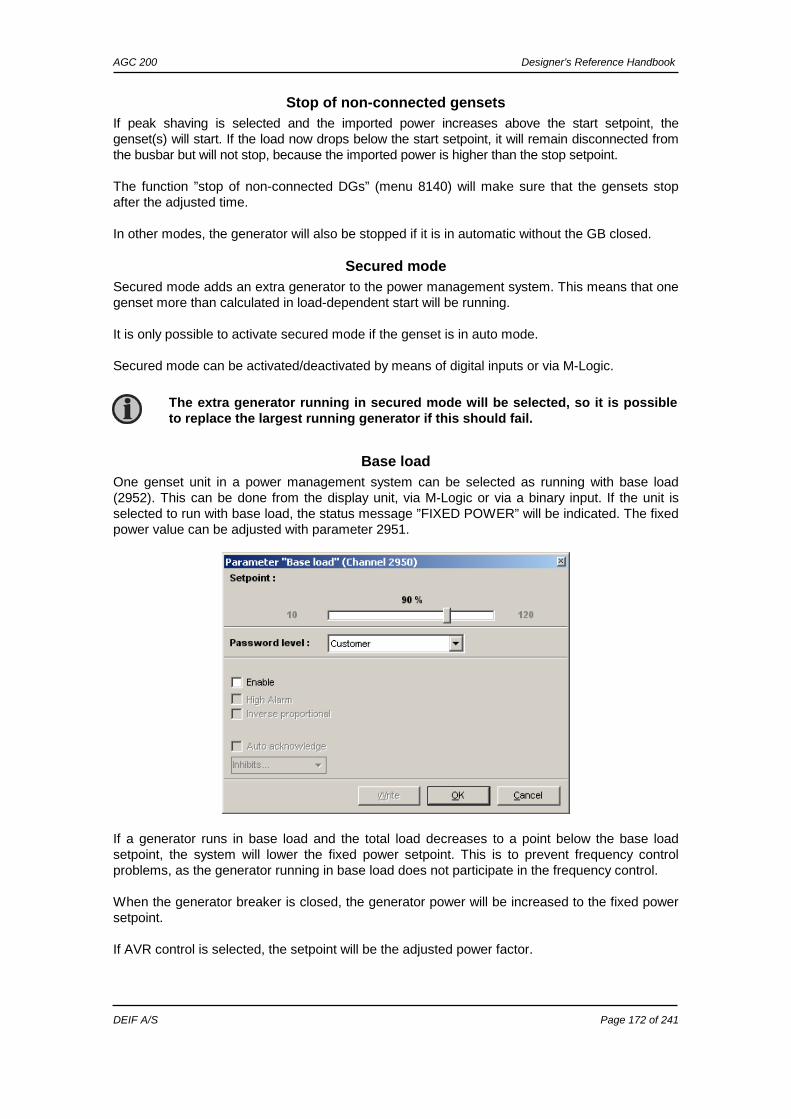
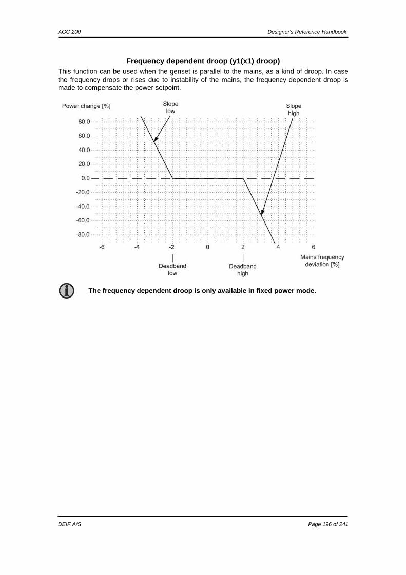
Fixed power/base load
Auto mode description
The unit automatically starts the genset and synchronises to the mains when the digital input ”auto start/stop” is activated. After the generator breaker closure, the unit ramps up the load to the setpoint level. When the stop command is given, the genset is deloaded and stopped after the cooling-down period. The start and stop commands are used by activating and deactivating a digital input. If the time-dependent start/stop commands are to be used, then the auto mode must also be used. In this case, the digital input ”auto start/stop” cannot be used.
Diagram, fixed power - principle
Semi-auto mode description
When the generator breaker is closed and the mains breaker is opened, the unit will use the nominal frequency as the setpoint for the speed governor and the nominal voltage for the AVR. When the generator is paralleled to the mains, the generator power will be increased to the fixed power setpoint (menu 7051). If AVR control is selected, then the setpoint will be the adjusted power factor (7052).
Setpoints related to fixed power
2610 Power ramp-up Ramp speed: Defines the slope of the ramp-up. Delay point: At this point, the ramp-up is cancelled until the delay has expired. Delay: When this delay has expired, the ramp-up is continued from the delay point. Enable: Enable load ramp steps. Steps: Defines the number of steps related to the delay point setting.
kW
Sta
rt s
igna
l
Sto
p si
gnal
tRAMP-UP t
For a general description of the available running modes, please refer to the chapter ”Running mode description”.
AGC 200 Designer’s Reference Handbook
DEIF A/S Page 16 of 241
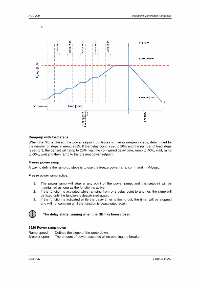
Ramp-up with load steps
When the GB is closed, the power setpoint continues to rise in ramp-up steps, determined by the number of steps in menu 2615. If the delay point is set to 20% and the number of load steps is set to 3, the genset will ramp to 20%, wait the configured delay time, ramp to 40%, wait, ramp to 60%, wait and then ramp to the present power setpoint.
Freeze power ramp
A way to define the ramp-up steps is to use the freeze power ramp command in M-Logic. Freeze power ramp active:
1. The power ramp will stop at any point of the power ramp, and this setpoint will be maintained as long as the function is active.
2. If the function is activated while ramping from one delay point to another, the ramp will be fixed until the function is deactivated again.
3. If the function is activated while the delay timer is timing out, the timer will be stopped and will not continue until the function is deactivated again.
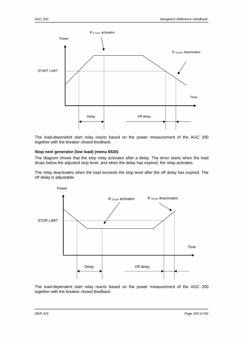
2620 Power ramp-down
Ramp speed: Defines the slope of the ramp-down. Breaker open: The amount of power accepted when opening the breaker.
The delay starts running when the GB has been closed.
AGC 200 Designer’s Reference Handbook
DEIF A/S Page 17 of 241
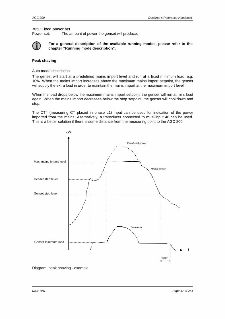
7050 Fixed power set Power set: The amount of power the genset will produce.
Peak shaving
Auto mode description
The genset will start at a predefined mains import level and run at a fixed minimum load, e.g. 10%. When the mains import increases above the maximum mains import setpoint, the genset will supply the extra load in order to maintain the mains import at the maximum import level. When the load drops below the maximum mains import setpoint, the genset will run at min. load again. When the mains import decreases below the stop setpoint, the genset will cool down and stop. The CT4 (measuring CT placed in phase L1) input can be used for indication of the power imported from the mains. Alternatively, a transducer connected to multi-input 46 can be used. This is a better solution if there is some distance from the measuring point to the AGC 200.
Diagram, peak shaving - example
Max. mains import level
Genset start level
Genset stop level
tSTOP
Genset minimum load
kW
Generator power
t
Mains power
Peak/total power
For a general description of the available running modes, please refer to the chapter ”Running mode description”.
AGC 200 Designer’s Reference Handbook
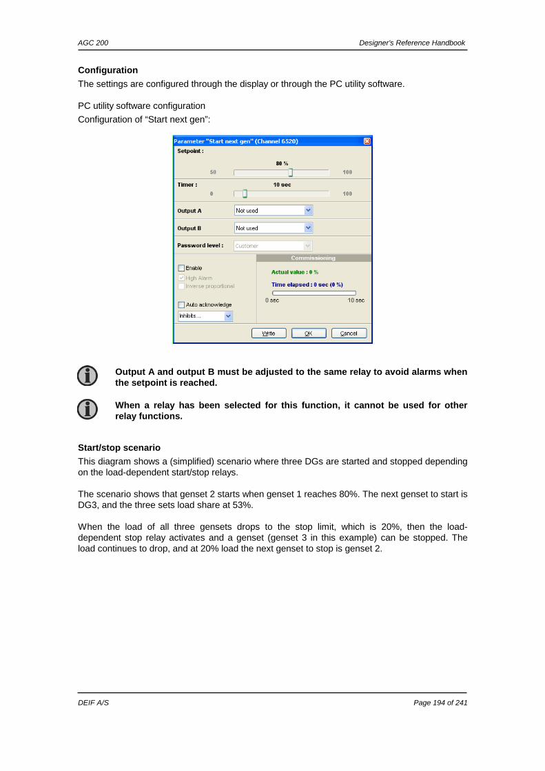
DEIF A/S Page 18 of 241
Semi-auto mode description
When the generator breaker is closed and the mains breaker is opened, the unit will use the nominal frequency as setpoint for the speed governor. If AVR control is selected, the nominal voltage is used as setpoint.
When the generator is paralleled to the mains, the generator will be controlled according to the peak shaving setpoint. So the maximum mains import will not be exceeded in spite of the semi- auto mode. If AVR control is selected, the setpoint is the adjusted power factor.
Setpoints related to peak shaving
7000 Mains power Day and night: The mains power import limits for the peak shaving. Tmax and Tmin: The transducer range in kW, corresponding to the 4-20 mA transducer signal
connected on multi-input 46. 7010 Daytime period These settings define the daytime period. The hours outside the daytime period are considered to be the night-time period. 7020 Start generator Start setpoint: The start setpoint is in percent of the day and night settings in menu 7000
Mains power. Delay: The genset will start when the start setpoint has been exceeded and this delay
has expired. Load: The minimum load the genset will produce when parallel to mains. 7030 Stop generator Stop setpoint: The stop setpoint is in percent of the day and night settings in menu 7000
Mains power. Delay: The genset will stop when the stop setpoint has been exceeded and this delay
has expired.
Load takeover
Auto mode description
- Back synchronising ON The purpose of the load takeover mode is to transfer the load imported from the mains to the genset for operation on generator supply only. When the start command is given, the genset will start and synchronise the generator breaker to the busbar that is being supplied by the mains. When the generator breaker is closed, the imported load is decreased (the power is being transferred to the genset) until the load is at the open breaker point. Then the mains breaker opens. When the stop command is given, the mains breaker is synchronised to the busbar and after closure the genset is deloaded, cooled down and stopped. The CT4 (measuring CT placed in phase L1) input can be used for indication of the power imported from the mains. Alternatively, a transducer connected to multi-input 46 can be used. This is a better solution if there is some distance from the measuring point to the AGC 200.
For a general description of the available running modes, please refer to the chapter ”Running mode description”.
AGC 200 Designer’s Reference Handbook
DEIF A/S Page 19 of 241
Diagram, load takeover - example
Back synchronising OFF When the start command is given, the genset will start. When the frequency and voltage is OK, the mains breaker is opened and the generator breaker is closed. Now, the generator supplies the load until the stop command is given. Then, the generator breaker opens and the mains breaker closes. The genset cools down and stops. The CT4 (measuring CT placed in phase L1) input can be used for indication of the power imported from the mains. Alternatively, a transducer connected to multi-input 46 can be used. This is a better solution if there is some distance from the measuring point to the AGC 200.
Semi-auto mode
When the generator breaker is closed and the mains breaker is opened, the unit will use the nominal frequency as setpoint for the speed governor. If AVR control is selected, the nominal voltage is used as setpoint. When the generator is paralleled to the mains, it will be controlled so the imported power from the mains will be kept at 0 kW. If AVR control is selected, the setpoint is the adjusted power factor.
kW
Sta
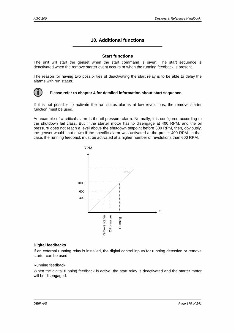
rt s
igna
l
Sto
p si
gnal
Mains power Generator power
MB
ope
ns
GB
ope
ns
t
The load takeover mode can be combined with the overlap function. In that case, the generator and the mains breakers will never be closed at the same time for a longer period than the adjusted ”overlap” time.
If the imported load is higher than the nominal genset power, an alarm appears and the load takeover sequence is paused.
If the imported load is higher than the nominal genset power, an alarm appears and the load takeover sequence is paused.
For a general description of the available running modes, please refer to the chapter ”Running mode description”.
AGC 200 Designer’s Reference Handbook
DEIF A/S Page 20 of 241
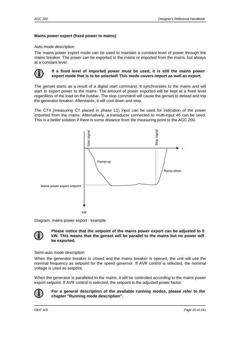
Mains power export (fixed power to mains)
Auto mode description
The mains power export mode can be used to maintain a constant level of power through the mains breaker. The power can be exported to the mains or imported from the mains, but always at a constant level. The genset starts as a result of a digital start command. It synchronises to the mains and will start to export power to the mains. The amount of power exported will be kept at a fixed level regardless of the load on the busbar. The stop command will cause the genset to deload and trip the generator breaker. Afterwards, it will cool down and stop. The CT4 (measuring CT placed in phase L1) input can be used for indication of the power imported from the mains. Alternatively, a transducer connected to multi-input 46 can be used. This is a better solution if there is some distance from the measuring point to the AGC 200.
Diagram, mains power export - example
Semi-auto mode description
When the generator breaker is closed and the mains breaker is opened, the unit will use the nominal frequency as setpoint for the speed governor. If AVR control is selected, the nominal voltage is used as setpoint. When the generator is paralleled to the mains, it will be controlled according to the mains power export setpoint. If AVR control is selected, the setpoint is the adjusted power factor.
Mains power export setpoint
Ramp-up
Ramp-down
kW
t
Sta
rt s
igna
l
Sto
p si
gnal
Please notice that the setpoint of the mains power export can be adjusted to 0 kW. This means that the genset will be parallel to the mains but no power will be exported.
If a fixed level of imported power must be used, it is still the mains power export mode that is to be selected! This mode covers import as well as export.
For a general description of the available running modes, please refer to the chapter ”Running mode description”.
AGC 200 Designer’s Reference Handbook
DEIF A/S Page 21 of 241
Running mode description
Semi-auto mode
The unit can be operated in semi-auto mode. Semi-auto means that the unit will not initiate any sequences automatically, as is the case with the auto mode. It will only initiate sequences if external signals are given. An external signal may be given in three ways:
1. Push-buttons on the front are used. 2. Digital inputs are used. 3. Modbus command.
When the genset is running in semi-auto mode, the unit will control the speed governor and the AVR. The following sequences can be activated in semi-auto: Command Description Comment Start The start sequence is initiated and continues until the
genset starts or the maximum number of start attempts has been reached. The frequency (and voltage) will be regulated to make the GB ready to close.
Stop The genset will be stopped. After disappearance of the running signal, the stop sequence will continue to be active in the ”extended stop time” period. The genset is stopped without cooling-down time.
Close GB The unit will close the generator breaker if the mains breaker is open, and it will synchronise and close the generator breaker if the mains breaker is closed.
When AMF mode is selected, the unit will not regu-late after breaker closure.
Open GB The unit will ramp down and open the generator breaker at the breaker open point if the mains breaker is closed. The unit will open the generator breaker instantly if the mains breaker is open or the genset mode is island mode.
Close MB The unit will close the mains breaker if the generator breaker is open, and it will synchronise and close the mains breaker if the generator breaker is closed.
Open MB The unit opens the mains breaker instantly. Manual GOV UP
The regulator is deactivated and the governor output is activated as long as the GOV input is ON.
Manual GOV DOWN
The regulator is deactivated and the governor output is activated as long as the GOV input is ON.
Manual AVR UP
The regulator is deactivated and the governor output is activated as long as the AVR input is ON.
Manual AVR DOWN
The regulator is deactivated and the governor output is activated as long as the AVR input is ON.
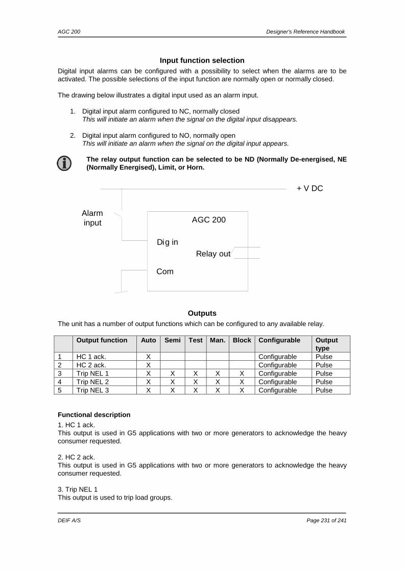
The standard AGC 200 is equipped with a limited number of digital inputs, please refer to the chapter ”Digital inputs” in this document and the data sheet for additional information about availability.
AGC 200 Designer’s Reference Handbook
DEIF A/S Page 22 of 241
Test mode
The test mode function is activated by selecting test with the MODE push-button on the display or by activating a digital input. The settings for the test function are set up in menu 7040.
• Setpoint: Load setpoint when paralleling to mains.
• Timer: Engine run time during the test period. • Return: When the test is completed, the unit will return to the selected mode
(semi-auto or auto).
• Type: Selection of one of the three types of tests: Simple, load or full.
Simple test
The simple test will only start the genset and run it at nominal frequency with the generator breaker open. The test will run until the timer expires.
Load test
The load test will start the genset and run it at nominal frequency, synchronise the generator breaker and produce the power typed in the setpoint in menu 7041. The test will run until the timer expires.
Full test
The full test will start the genset and run it at nominal frequency, synchronise the generator breaker and transfer the load to the generator before opening the mains breaker. When the test timer expires, the mains breaker will be synchronised and the load is transferred back to the mains before the generator breaker is opened and the generator is stopped.
To run the full test, it is required that ”Sync. to mains” is enabled in menu 7084.
When running a load test sequence, the overlap function is ignored.
Test mode cannot be used if the genset is in island operation (genset mode selected to island mode).
Power management (option G4): Test mode is not available.
If the timer is set to 0.0 min., the test sequence will be infinite.
To run the load test, it is required that ”Sync. to mains” is enabled in menu 7084.
AGC 200 Designer’s Reference Handbook
DEIF A/S Page 23 of 241
Manual mode
When manual mode is selected, the genset can be controlled with digital inputs. The following commands are possible:
Command Comment Start (input or push-button) Genset starts (no regulation). Stop (input or push-button) Genset opens GB and stops without
cooling down. Manual increase speed Unit gives increase signal to the speed
governor. Manual decrease speed Unit gives decrease signal to the speed
governor. Manual increase voltage Unit gives increase signal to the AVR. Manual decrease voltage Unit gives decrease signal to the AVR.
OFF mode
When the OFF mode is selected, the unit is locked for certain actions. This means that it cannot start the genset or perform any breaker operations. The purpose of the OFF mode is to make sure that the genset does not start for instance during maintenance work. If the digital inputs are used to change the mode, then it is important to keep in mind that the input configured to OFF mode is a constant signal. So, when it is ON, the unit is in a blocked state and when it is OFF, it returns to the mode it was in before OFF mode was selected.
It is not possible to open and close the generator breaker or the mains breaker in manual mode.
It is necessary to configure the digital inputs through the PC utility software to use the manual commands. The number of configurable digital inputs is option-dependent.
MAN mode cannot be selected, when AUTO mode is selected. To go from AUTO to MAN, it is necessary to go to SEMI-AUTO to make MAN available.
Alarms are not influenced by OFF mode selection.
The genset can be started from the local engine control panel if such is installed. Therefore, DEIF recommends avoiding local cranking and starting of the genset.
If OFF mode is selected using the display after the digital OFF input is activated, the AGC 200 will stay in OFF mode after the OFF input is deactivated. The OFF mode must now be changed using the display. The OFF mode can only be changed locally by display or digital input.
Before the running mode is changed, it is important to check that persons are clear of the genset and that the genset is ready for operation.
If OFF mode is selected when the generator is running, the breaker will open and the engine will be stopped immediately.
AGC 200 Designer’s Reference Handbook
DEIF A/S Page 24 of 241
Single-line diagrams In the following, the various applications are illustrated in single-line diagrams.
Island operation
Automatic Mains Failure/fixed power/base load
Peak shaving/load takeover/mains power export
Multiple gensets, load sharing
AGC 200
AGC 200
AGC 200
AGC 200
AGC 200
AGC 200 Designer’s Reference Handbook
DEIF A/S Page 25 of 241
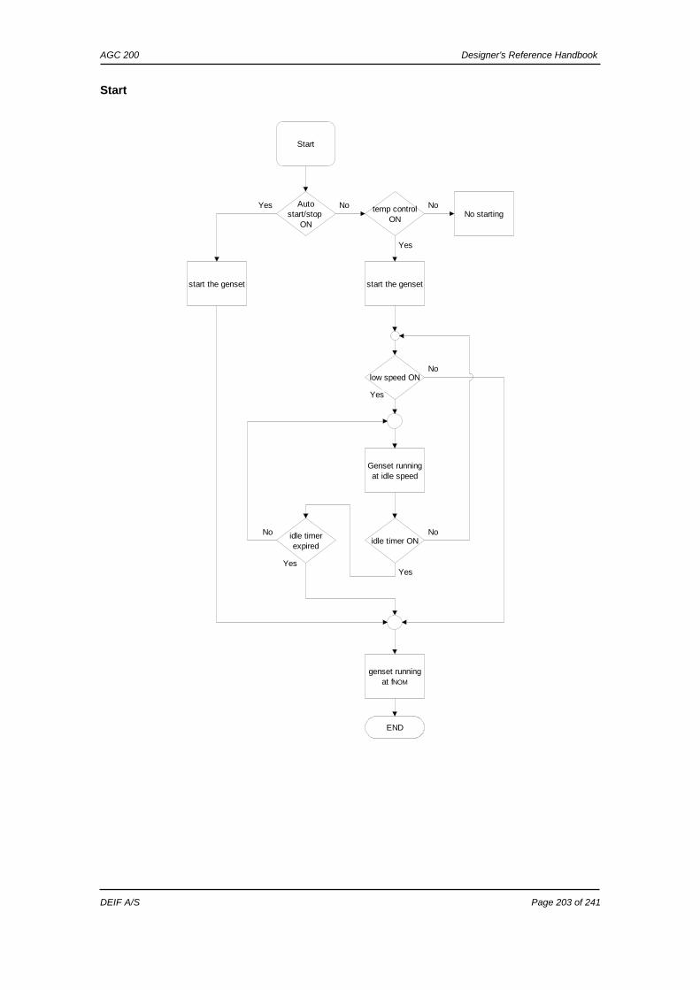
Flowcharts Using flowcharts, the principles of the most important functions will be illustrated in the next sections. The functions included are:
• Mode shift • MB open sequence • GB open sequence • Stop sequence • Start sequence • MB close sequence • GB close sequence • Fixed power • Load takeover • Single generator/island operation • Peak shaving • Mains power export • Automatic Mains Failure • Test sequence
The following flowcharts are for guidance only. For illustrative purposes, the flowcharts are simplified.
AGC 200 Designer’s Reference Handbook
DEIF A/S Page 26 of 241
Mode shift
Start
Mode shiftenabled
Mode notisland/AMF
Yes
Mains failure
Yes
Initiate AMFsequence
Yes
Mains OKInitiate mains
returnsequence
Yes
END
No
No
No
No MB closesequence
Continue inselected mode
AGC 200 Designer’s Reference Handbook
DEIF A/S Page 27 of 241
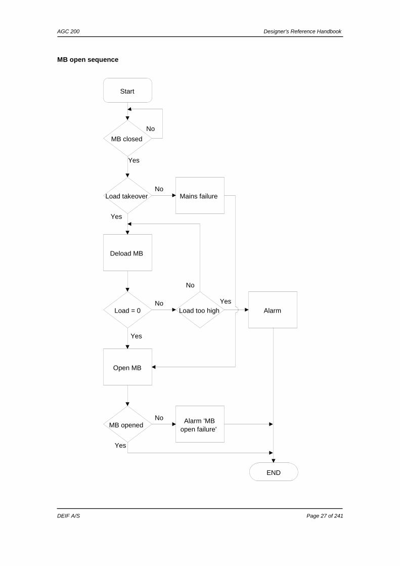
MB open sequence
Start
MB closed
Load takeover
Yes
Deload MB
Yes
Load = 0
Open MB
Yes
MB openedAlarm 'MB
open failure'
No
Load too highNo
AlarmYes
END
Mains failureNo
No
No
Yes
AGC 200 Designer’s Reference Handbook
DEIF A/S Page 28 of 241
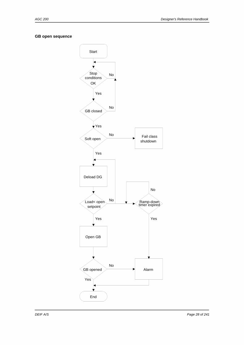
GB open sequence
Start
Stop conditions
OK
GB closed
Yes
No
No
Soft open
Yes
Fail classshutdown
No
Deload DG
Yes
Load< opensetpoint
No
Open GB
Yes
GB opened AlarmNo
End
Yes
Ramp-downtimer expired
Yes
No
AGC 200 Designer’s Reference Handbook
DEIF A/S Page 29 of 241
Stop sequence
Start
Stopconditions
OK
GB openseq. OK
Yes
AUTOmode
Yes
Cooldowntimer run
out
Yes
Run coil
Yes
No
No
No
No
Stop relayNo
Activate stoprelay
Deactivate'stop' relay
Yes
Gensetstopped Alarm
No
End
Yes
AGC 200 Designer’s Reference Handbook
DEIF A/S Page 30 of 241
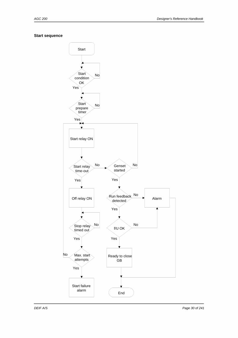
Start sequence
Start
Start condition
OK
Start prepare
timer
Yes
No
No
Start relay ON
Yes
Start relaytime-out
Gensetstarted
No No
Run feedbackdetected
Yes
Off relay ON
Yes
Stop relaytimed out
Max. startattempts
Yes
No
No
Alarm No
f/U OK
Yes
End
Ready to closeGB
Yes
No
Start failurealarm
Yes
AGC 200 Designer’s Reference Handbook
DEIF A/S Page 31 of 241
MB close sequence
Start
Is MB open
Voltage onon
gen.
No
GB closed
Yes
Back sync. ON
YesDirect close OK
No
Voltage onmains
No
Yes
Yes
No
GB opensequence
No
Sync. MB
Yes
Synchronised
Close MB
Yes
MB closed
End
Yes
Close failure
alarm
No
Sync. timerrun out
No
No
Alarm sync.failure
Yes Alarm GB openfailure
No
Yes
AGC 200 Designer’s Reference Handbook
DEIF A/S Page 32 of 241
GB close sequence
Start
is GB openNo
Start seq OK
Yes
No
DG freq match BB freq
time runout
No
direct closing OK
close GB
Yes
alarm sync failure
Yes
GB closed alarmNo
end
Yes
single DG application
Yes
voltage on busbar
No
island mode
Yes
voltage on bus
Yes
MB close
No
Yes Yes
All GBs OFF
No
TB Present
Yes
TB open
Yes
MB open
No
Sync GB
No Yes
No
Yes
No
Yes
No
No
No
AGC 200 Designer’s Reference Handbook
DEIF A/S Page 33 of 241
Fixed power
Start
Activate start input
start sequence
GB close sequence
ramp-up to load set-point
deactivate start input
operation
GB open sequence
stop sequence
end
AGC 200 Designer’s Reference Handbook
DEIF A/S Page 34 of 241
Load takeover
Start
Activate start input
start sequence
GB close sequence
Mains load = 0 kW
ramp-up genset load
No
MB open sequence
Yes
deactivate start input
MB close sequence
GB open sequence
genset operation
stop sequence end
AGC 200 Designer’s Reference Handbook
DEIF A/S Page 35 of 241
Single generator island operation
Start
start input active
start sequence
GB close sequence
operation
start input deactivated
GB open sequence
stop sequence
end
AGC 200 Designer’s Reference Handbook
DEIF A/S Page 36 of 241
Peak shaving
Start
mains power above start set
point
start sequence
GB close sequence
operation:produce power above set point
mains power below stop set
point
GB open sequence
stop sequence
end
AGC 200 Designer’s Reference Handbook
DEIF A/S Page 37 of 241
Mains power export
Start
activate start input
start sequence
close GB sequence
ramp up to MPE set point
Operation
deactivate start input
GB open sequence
stop sequence
end
AGC 200 Designer’s Reference Handbook
DEIF A/S Page 38 of 241
Automatic Mains Failure
AGC 200 Designer’s Reference Handbook
DEIF A/S Page 39 of 241
Test sequence
AGC 200 Designer’s Reference Handbook
DEIF A/S Page 40 of 241
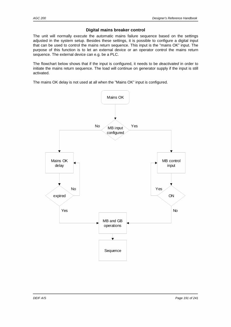
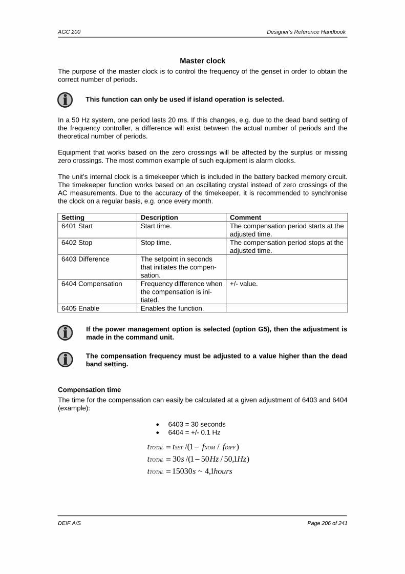
Sequences The following contains information about the sequences of the engine, the generator breaker and, if installed, the mains breaker. These sequences are automatically initiated if the auto mode is selected, or if the commands are selected in the semi-auto mode. In the semi-auto mode, the selected sequence is the only sequence initiated (e.g. press the START push-button: The engine will start, but no subsequent synchronising is initiated). The following sequences will be illustrated below:
If island operation is selected, the digital input ”MB closed” is NOT to be activated with a 12/24 volt input signal. A mains breaker failure will occur if the wiring of the mains breaker feedback inputs is wrong.
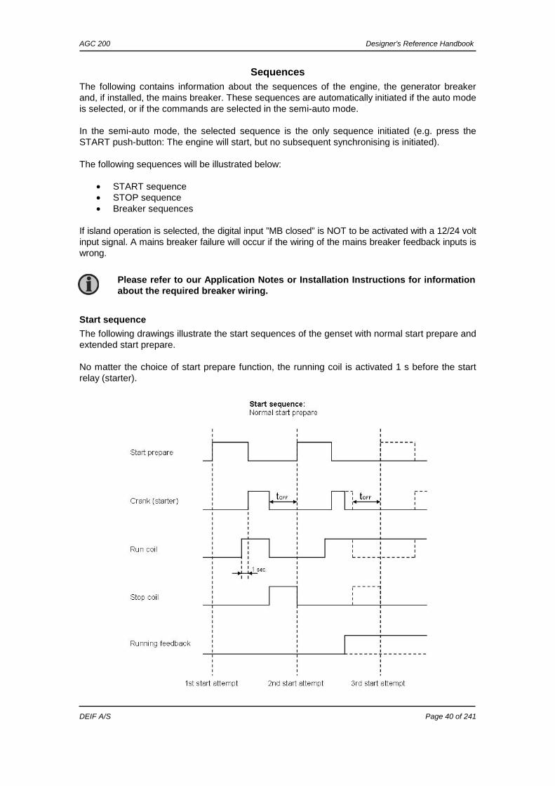
Start sequence
The following drawings illustrate the start sequences of the genset with normal start prepare and extended start prepare. No matter the choice of start prepare function, the running coil is activated 1 s before the start relay (starter).
Please refer to our Application Notes or Installation Instructions for information about the required breaker wiring.
AGC 200 Designer’s Reference Handbook
DEIF A/S Page 41 of 241
Start sequence conditions
The start sequence initiation can be controlled by the following conditions:
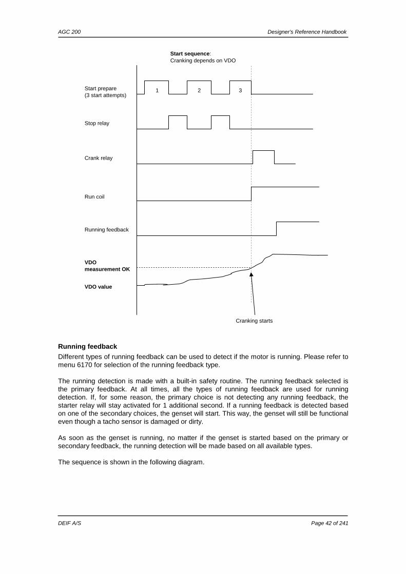
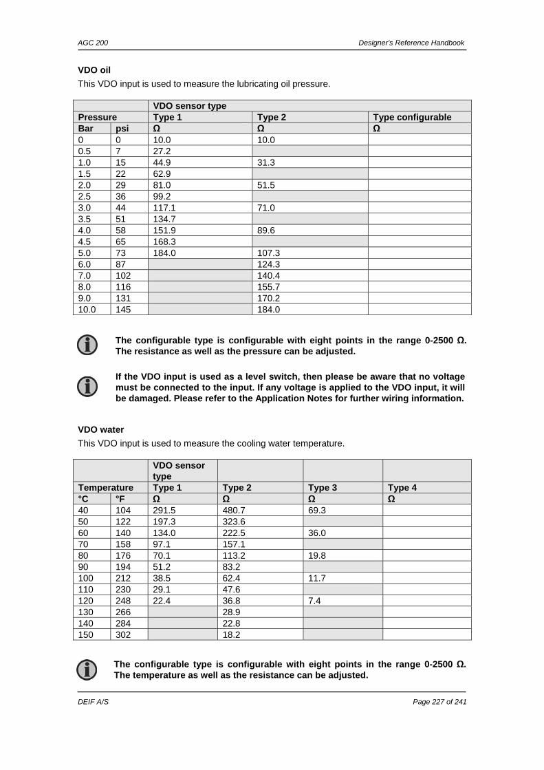
This means that if e.g. the oil pressure is not primed to the sufficient value, then the crank relay will not engage the starter motor. The selection is made in setting 6185. For each of the VDO settings, the rule is that the value (oil pressure, fuel level or water temperature) must exceed the setpoint of setting 6186 before starting is initiated. The following diagram shows an example where the VDO signal builds up slowly, and starting is initiated at the end of the third start attempt.
If the value in 6186 is set to 0.0, the start sequence is initiated as soon as it is requested.
AGC 200 Designer’s Reference Handbook
DEIF A/S Page 42 of 241
Running feedback
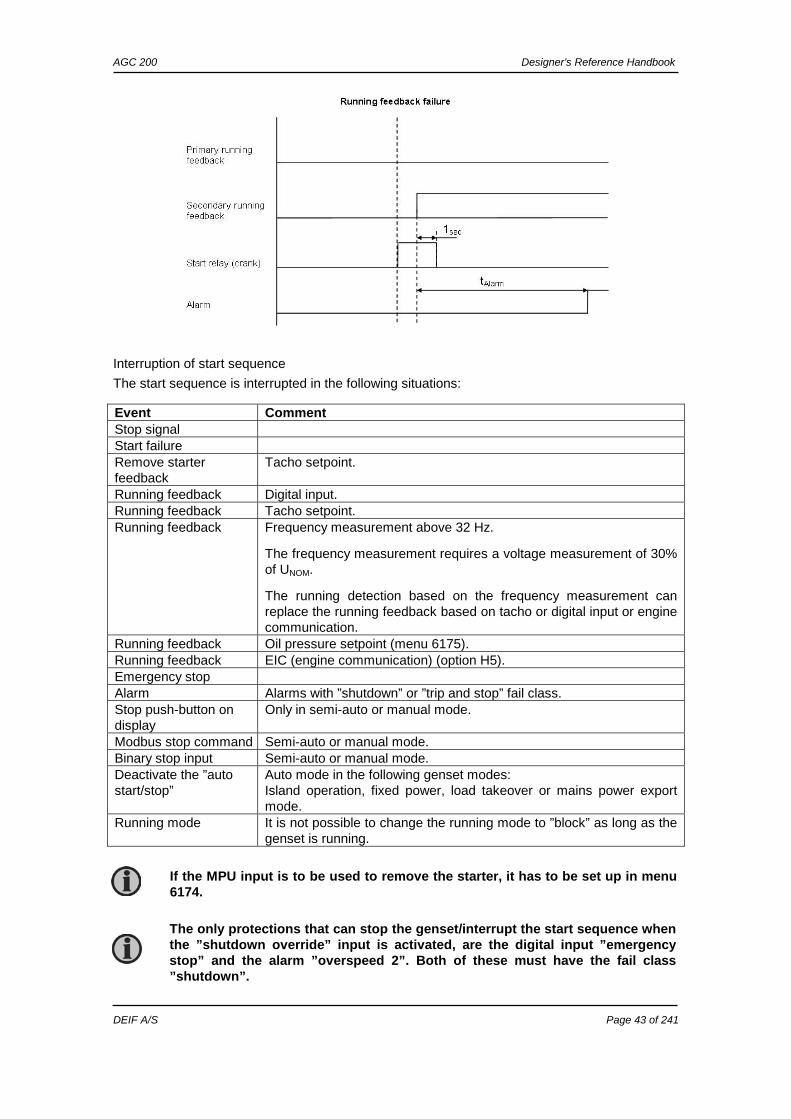
Different types of running feedback can be used to detect if the motor is running. Please refer to menu 6170 for selection of the running feedback type. The running detection is made with a built-in safety routine. The running feedback selected is the primary feedback. At all times, all the types of running feedback are used for running detection. If, for some reason, the primary choice is not detecting any running feedback, the starter relay will stay activated for 1 additional second. If a running feedback is detected based on one of the secondary choices, the genset will start. This way, the genset will still be functional even though a tacho sensor is damaged or dirty. As soon as the genset is running, no matter if the genset is started based on the primary or secondary feedback, the running detection will be made based on all available types. The sequence is shown in the following diagram.
Start sequence: Cranking depends on VDO
Start prepare (3 start attempts)
Stop relay
Running feedback
Crank relay
Run coil
VDO measurement OK
VDO value
Cranking starts
1 2 3
AGC 200 Designer’s Reference Handbook
DEIF A/S Page 43 of 241
Interruption of start sequence
The start sequence is interrupted in the following situations:
Event Comment Stop signal Start failure Remove starter feedback
Tacho setpoint.
Running feedback Digital input. Running feedback Tacho setpoint. Running feedback Frequency measurement above 32 Hz.
The frequency measurement requires a voltage measurement of 30% of UNOM.
The running detection based on the frequency measurement can replace the running feedback based on tacho or digital input or engine communication.
Running feedback Oil pressure setpoint (menu 6175). Running feedback EIC (engine communication) (option H5). Emergency stop Alarm Alarms with ”shutdown” or ”trip and stop” fail class. Stop push-button on display
Only in semi-auto or manual mode.
Modbus stop command Semi-auto or manual mode. Binary stop input Semi-auto or manual mode. Deactivate the ”auto start/stop”
Auto mode in the following genset modes: Island operation, fixed power, load takeover or mains power export mode.
Running mode It is not possible to change the running mode to ”block” as long as the genset is running.
If the MPU input is to be used to remove the starter, it has to be set up in menu 6174.
The only protections that can stop the genset/interrupt the start sequence when the ”shutdown override” input is activated, are the digital input ”emergency stop” and the alarm ”overspeed 2”. Both of these must have the fail class ”shutdown”.
AGC 200 Designer’s Reference Handbook
DEIF A/S Page 44 of 241
Setpoints related to the start sequence
- Crank failure alarm (4530 Crank failure) If MPU is chosen as the primary running feedback, this alarm will be raised if the specified rpm is not reached before the delay has expired. - Run feedback failure (4540 Run feedb. fail) If running is detected on the frequency (secondary), but the primary running feedback, e.g. digital input, has not detected running, this alarm will be raised. The delay to be set is the time from the secondary running detection and until the alarm is raised. - Hz/V failure (4550 Hz/V failure) If the frequency and voltage are not within the limits set in menu 2110 after the running feedback is received, this alarm is raised when the delay has expired. - Start failure alarm (4570 Start failure) The start failure alarm occurs, if the genset has not started after the number of start attempts set in menu 6190. - Start prepare (6180 Starter) Normal prepare: The start prepare timer can be used for start preparation purposes, e.g. prelubrication or preglowing. The start prepare relay is activated when the start sequence is initiated and deactivated when the start relay is activated. If the timer is set to 0.0 s, the start prepare function is deactivated. Extended prepare: The extended prepare will activate the start prepare relay when the start sequence is initiated and keep it activated when the start relay activates until the specified time has expired. If the ext. prepare time exceeds the start ON time, the start prepare relay is deactivated when the start relay deactivates. If the timer is set to 0.0 s, the extended prepare function is deactivated. Start ON time: The starter will be activated for this period when cranking. Start OFF time: The pause between two start attempts.
AGC 200 Designer’s Reference Handbook
DEIF A/S Page 45 of 241
Stop sequence
The drawings illustrate the stop sequence.
The stop sequence will be activated if a stop command is given. The stop sequence includes the cooling down time if the stop is a normal or controlled stop.
Description Cooling down Stop Comment Auto mode stop X X Trip and stop alarm X X Stop button on display X Semi-auto or manual. Remove ”auto start/stop” X X Auto mode: Island operation, fixed
power, load takeover, mains power export.
Emergency stop X Engine shuts down and GB opens.
AGC 200 Designer’s Reference Handbook
DEIF A/S Page 46 of 241
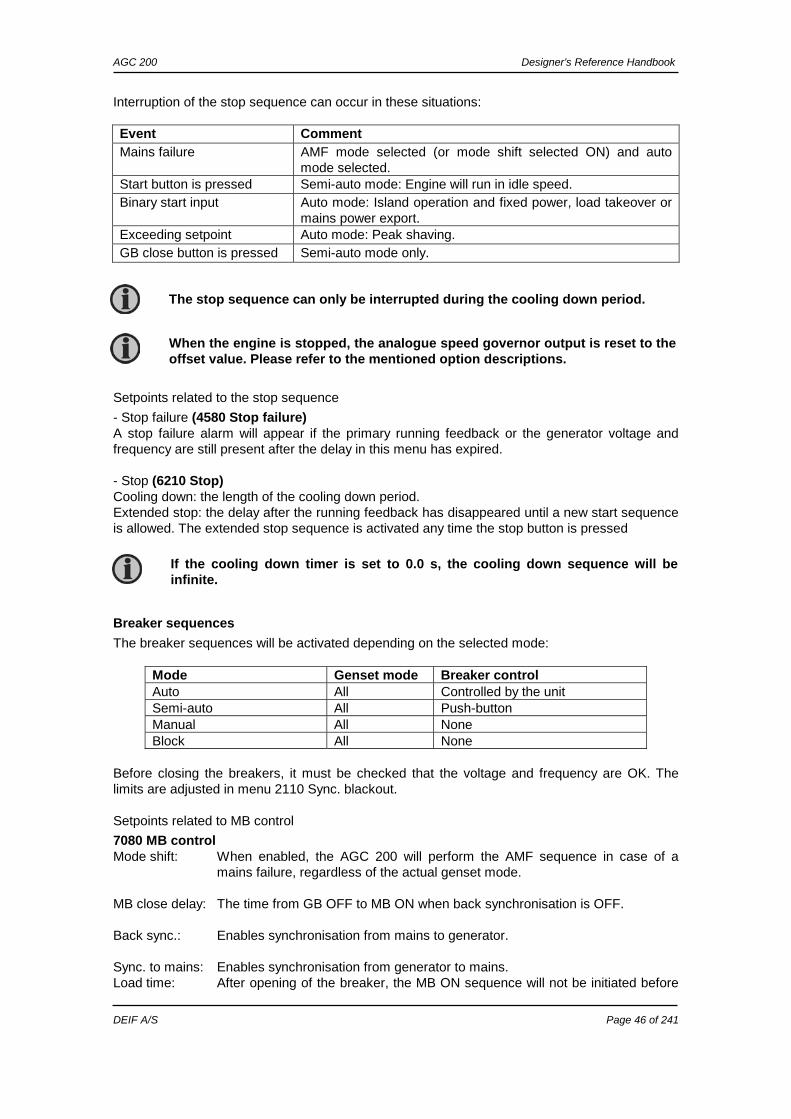
Interruption of the stop sequence can occur in these situations:
Setpoints related to the stop sequence
- Stop failure (4580 Stop failure) A stop failure alarm will appear if the primary running feedback or the generator voltage and frequency are still present after the delay in this menu has expired. - Stop (6210 Stop) Cooling down: the length of the cooling down period. Extended stop: the delay after the running feedback has disappeared until a new start sequence is allowed. The extended stop sequence is activated any time the stop button is pressed
Breaker sequences
The breaker sequences will be activated depending on the selected mode:
Mode Genset mode Breaker control Auto All Controlled by the unit Semi-auto All Push-button Manual All None Block All None
Before closing the breakers, it must be checked that the voltage and frequency are OK. The limits are adjusted in menu 2110 Sync. blackout.
Setpoints related to MB control
7080 MB control Mode shift: When enabled, the AGC 200 will perform the AMF sequence in case of a
mains failure, regardless of the actual genset mode. MB close delay: The time from GB OFF to MB ON when back synchronisation is OFF. Back sync.: Enables synchronisation from mains to generator. Sync. to mains: Enables synchronisation from generator to mains. Load time: After opening of the breaker, the MB ON sequence will not be initiated before
Event Comment Mains failure AMF mode selected (or mode shift selected ON) and auto
mode selected. Start button is pressed Semi-auto mode: Engine will run in idle speed. Binary start input Auto mode: Island operation and fixed power, load takeover or
mains power export. Exceeding setpoint Auto mode: Peak shaving. GB close button is pressed Semi-auto mode only.
The stop sequence can only be interrupted during the cooling down period.
When the engine is stopped, the analogue speed governor output is reset to the offset value. Please refer to the mentioned option descriptions.
If the cooling down timer is set to 0.0 s, the cooling down sequence will be infinite.
AGC 200 Designer’s Reference Handbook
DEIF A/S Page 47 of 241
this delay has expired. Please refer to the description of ”breaker spring load time”.
- AMF MB opening function (menu 7065) It is possible to select the functionality of the mains breaker closing function. This is necessary if the unit operates in Automatic Mains Failure (AMF). The possibilities are:
Selection Description
Start engine and open mains breaker
When a mains failure occurs, the mains breaker opens and the engine starts at the same time.
Start engine When a mains failure occurs, the engine starts. When the generator is running and the frequency and voltage are OK, the MB opens and the GB closes.
AMF timers
The time charts describe the functionality at a mains failure and at mains return. Back synchronisation is deactivated. The timers used by the AMF function are indicated in the table below:
Timer Description Menu number
tFD Mains failure delay 7070 f mains failure 7060 U mains failure
tFU Frequency/voltage OK 6220 Hz/V OK tFOD Mains failure OK delay 7070 f mains failure
7060 U mains failure tGBC GB ON delay 6231 GB close delay tMBC MB ON delay 7085 MB load time
The timer tMBC is only active if back synchronisation is deactivated.
AGC 200 without back synchronisation: The GB can only be closed if the mains breaker is open. The MB can only be closed if the generator breaker is open.
AGC 200 with back synchronisation: If the GB or MB push-button is activated, the AGC 200 will start synchronising if the generator or mains voltage is present. The GB can close directly if the MB is open. The MB can close directly if the GB is open.
If no MB is represented, then the relays and inputs normally used for MB control become configurable. The power plant constructor (USW) is used for configuration of the plant design if the application does not include an MB.
AGC 200 Designer’s Reference Handbook
DEIF A/S Page 48 of 241
Example 1: 7065 Mains fail control: Start engine and open MB
Example 2: 7065 Mains fail control: Start engine
GB On
MB On
Mains failure detected
Gen start seq tFD
Gen stop seq
Mains OK
Mains OK
tFOD
Gen running
Gen f/U OK
tMCB
tFU
tGBC GB On
MB On
Mains failure detected
Gen start seq tFD
Gen stop seq
Mains OK
Mains OK
tFOD
tFU
tMBC
Gen running
Gen f/U OK
AGC 200 Designer’s Reference Handbook
DEIF A/S Page 49 of 241
Conditions for breaker operations
The breaker sequences react depending on the breaker positions and the frequency/voltage measurements. The conditions for the ON and OFF sequences are described in the table below:
Conditions for breaker operations
Sequence Condition
GB ON, direct closing Running feedback Generator frequency/voltage OK MB open
MB ON, direct closing Mains frequency/voltage OK GB open
GB ON, synchronising Running feedback
Generator frequency/voltage OK MB closed No generator failure alarms
MB ON, synchronising Mains frequency/voltage OK GB closed No generator failure alarms
GB OFF, direct opening MB open MB OFF, direct opening Alarms with fail classes:
Shut down or Trip MB alarms GB OFF, deloading MB closed MB OFF, deloading Alarms with fail class:
Trip and stop
AGC 200 Designer’s Reference Handbook
DEIF A/S Page 50 of 241
5. Display and menu structure This chapter deals with the display including the push-button and LED functions. In addition, the unit menu structure will be presented. The display has six different lines, each with 25 characters. The display unit holds a number of push-button functions which are presented below.
Manoeuvring push-buttons
Moves the cursor left for manoeuvring in the menus.
Increases the value of the selected setpoint (in the setup menu). In the daily use display, this button function is used to scroll the view lines in V1 or the second line (in the setup menu) displaying of generator values.
Is used to select the entry in the display.
Decreases the value of the selected setpoint (in the setup menu). In the daily use display, this button function is used to scroll the second line displaying of generator values.
Moves the cursor right for manoeuvring in the menus.
ESC Jumps one step backwards in the menu (to previous display or to the entry window).
Alarm push-buttons
Shifts the display to alarm list. Silence horn.
Control and command push-buttons
Start of the genset if ”SEMI-AUTO” or ”MANUAL” is selected.
Stop of the genset if ”SEMI-AUTO” or ”MANUAL” is selected.
Manual activation of close breaker sequence if ”SEMI-AUTO” is selected.
Manual activation of open breaker sequence if ”SEMI-AUTO” is selected.
AGC 200 Designer’s Reference Handbook
DEIF A/S Page 51 of 241
Running mode selection push-buttons
AUTO Select AUTO running mode (start, stop and breaker push-buttons are ignored). SEMI Select SEMI-AUTO running mode (start, stop and breaker push-buttons are
active). MAN Manual running mode (start, stop and breaker push-buttons are active, but
regulators are not active). OFF OFF running mode. The AGC 200 will do nothing (alarms are active). TEST Initiates a test run (not possible for island generator).
Display view selection push-buttons
Shifts the display to show readings of values (AC values as well as analogue inputs and engine data).
Shifts the display lines 2-4 to show the alarm/log list. Shifts the display to system settings. Shifts the display to help tools.
AGC 200 Designer’s Reference Handbook
DEIF A/S Page 52 of 241
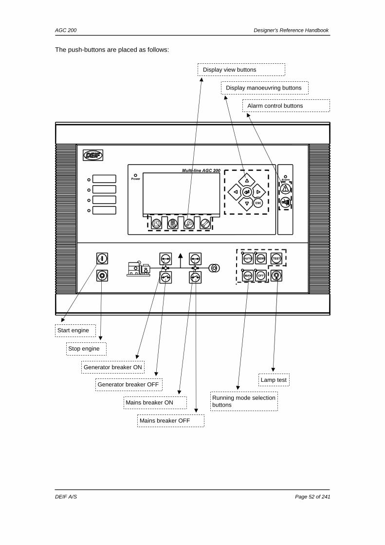
The push-buttons are placed as follows:
Display manoeuvring buttons
Start engine
Generator breaker ON
Lamp test
Running mode selection buttons
Stop engine
Generator breaker OFF
Mains breaker ON
Mains breaker OFF
Display view buttons
Alarm control buttons
AGC 200 Designer’s Reference Handbook
DEIF A/S Page 53 of 241
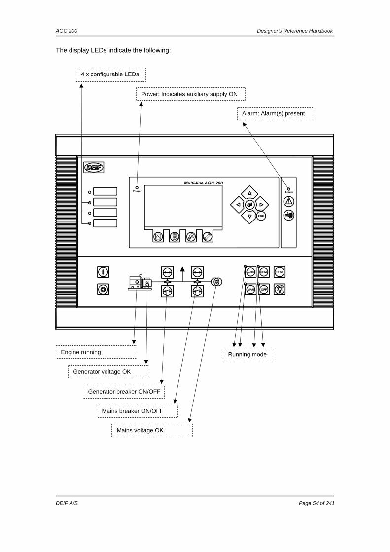
LED functions
The display unit holds up to 15 LED functions. Dependent on the situation, the colour of the LEDs is green, red or yellow. Alarm: LED flashing indicates that unacknowledged alarms are present. LED steady light indicates that ALL alarms are acknowledged. Power: LED indicates that the auxiliary supply is switched on. Alarm panel: Four pcs. LED indicators, configurable via M-Logic. Engine: LED indicates that the engine is running. Generator: LED green light indicates that the voltage/frequency is present and OK. GB ON: LED green light indicates that the generator breaker is closed. LED yellow light indicates that the generator breaker has received a command
to close on a black busbar, but the breaker is not yet closed due to interlocking of the GB.
LED is flashing yellow if the ”Enable GB black close” or the ”GB spring loaded” signal is missing or the GB load time has not expired.
GB OFF: LED red light indicates that the generator breaker is OFF. MB ON: LED green light indicates that the mains breaker is closed. LED is flashing yellow if the ”MB spring loaded” signal from the breaker is
missing or the MB load time has not expired. MB OFF: LED red light indicates that the mains breaker is OFF. Mains: LED is green if the mains is present and OK. LED is red at a measured mains failure. LED is flashing green when the mains returns during the ”mains OK delay” time. AUTO: LED indicates that auto mode is selected. SEMI: LED indicates that semi-auto mode is selected. MAN: LED indicates that manual mode is selected. OFF: LED indicates that off mode is selected.
AGC 200 Designer’s Reference Handbook
DEIF A/S Page 54 of 241
The display LEDs indicate the following:
Power: Indicates auxiliary supply ON
4 x configurable LEDs
Alarm: Alarm(s) present
Engine running
Generator voltage OK
Generator breaker ON/OFF
Mains breaker ON/OFF
Mains voltage OK
Running mode
AGC 200 Designer’s Reference Handbook
DEIF A/S Page 55 of 241
Menu structure The display includes two menu systems which can be used without password entry:
View menu system This is the commonly used menu system. 20 windows are configurable and can be entered by using the push-button. Setup menu system This menu system is used to set up the unit, and if the user needs detailed information that is not available in the view menu system. Changing of parameter settings is password protected.
Entry window
When the unit is powered up, an entry window appears. The entry window is the first window of the view menu system. It can always be reached by pushing the BACK push-button three times.
MAINS FAILURE U- supply 24.1 V G 0.00I PF 0 kW G 0kVA 0 kVAr Energy Total 0 kWh Run Absolute 0 hrs
AGC 200 Designer’s Reference Handbook
DEIF A/S Page 56 of 241
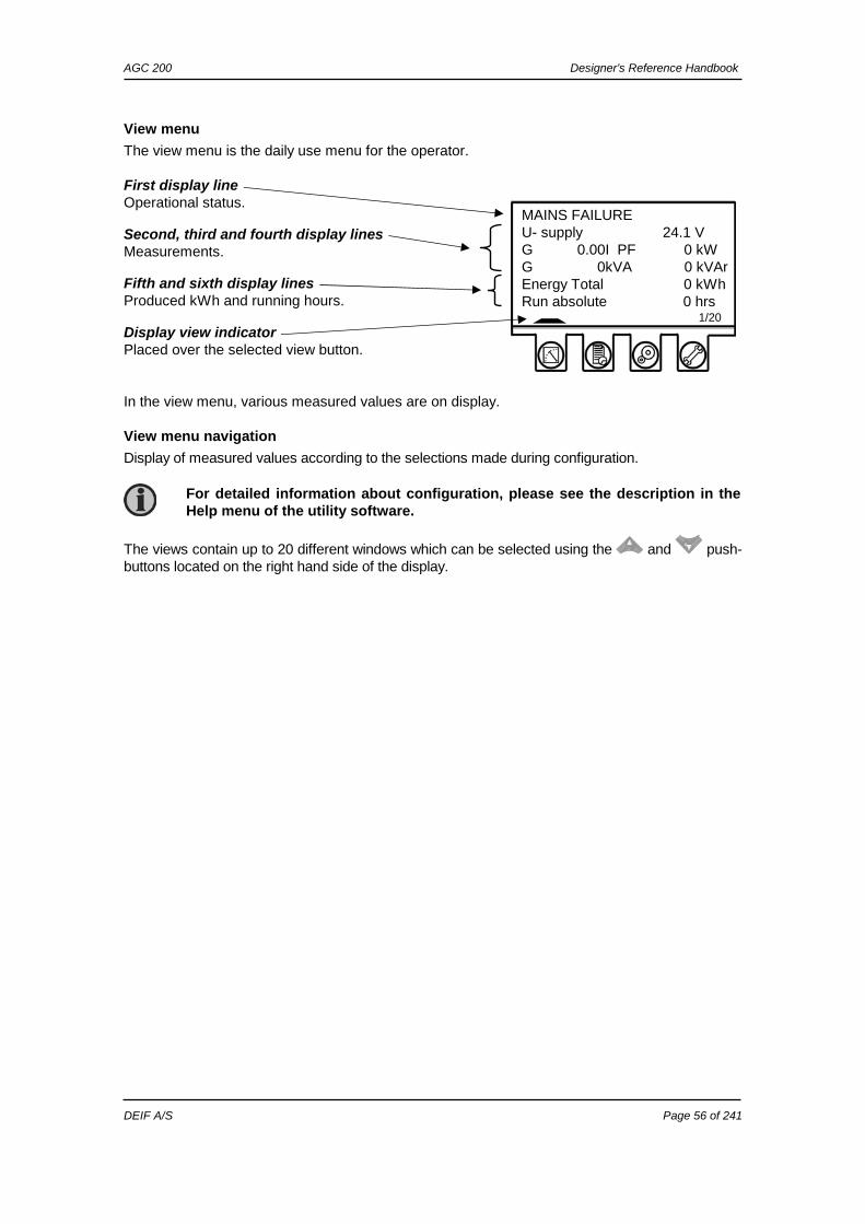
View menu
The view menu is the daily use menu for the operator. First display line Operational status. Second, third and fourth display lines Measurements. Fifth and sixth display lines Produced kWh and running hours. Display view indicator Placed over the selected view button. In the view menu, various measured values are on display.
View menu navigation
Display of measured values according to the selections made during configuration.
The views contain up to 20 different windows which can be selected using the and push-buttons located on the right hand side of the display.
For detailed information about configuration, please see the description in the Help menu of the utility software.
MAINS FAILURE U- supply 24.1 V G 0.00I PF 0 kW G 0kVA 0 kVAr Energy Total 0 kWh Run absolute 0 hrs 1/20
AGC 200 Designer’s Reference Handbook
DEIF A/S Page 57 of 241
Status line text This table explains the different messages. Status text Condition Comment BLOCK Block mode is activated SIMPLE TEST
Test mode is activated LOAD TEST FULL TEST SIMPLE TEST ###.#min
Test mode is activated and test timer counting down
LOAD TEST ###.#min FULL TEST ###.#min ISLAND MAN Genset stopped or running and
no other action taking place
ISLAND SEMI READY ISLAND AUTO Genset stopped in Auto ISLAND ACTIVE Genset running in Auto AMF MAN Genset stopped or running and
no other action taking place
AMF SEMI READY AMF AUTO Genset stopped in Auto AMF ACTIVE Genset running in Auto FIXED POWER MAN Genset stopped or running and
no other action taking place
FIXED POWER SEMI READY FIXED P AUTO Genset stopped in Auto FIXED POWER ACTIVE Genset running in Auto PEAK SHAVING MAN Genset stopped or running and
no other action taking place
PEAK SHAVING SEMI READY PEAK SHAV AUTO Genset stopped in Auto PEAK SHAVING ACTIVE Genset running in Auto LOAD TAKEOVER MAN Genset stopped or running and
no other action taking place
LOAD TAKEOVER SEMI READY LTO AUTO Genset stopped in Auto LTO ACTIVE Genset running in Auto MAINS P EXPORT MAN Genset stopped or running and
no other action taking place
MAINS P EXPORT SEMI READY MPE AUTO Genset stopped in Auto MPE ACTIVE Genset running in mains power
export mode
DG BLOCKED FOR START Generator stopped and active alarm(s) on the generator
GB ON BLOCKED Generator running, GB open and an active ”Trip GB” alarm
SHUTDOWN OVERRIDE The configurable input is active ACCESS LOCK The configurable input is
activated, and the operator tries to activate one of the blocked keys
GB TRIP EXTERNALLY Some external equipment has tripped the breaker
An external trip is logged in the event log
MB TRIP EXTERNALLY Some external equipment has tripped the breaker
An external trip is logged in the event log
IDLE RUN The ”Idle run” function is active The genset will not stop until a timer has expired
IDLE RUN ###.#min The timer in the ”Idle run” function is active
AGC 200 Designer’s Reference Handbook
DEIF A/S Page 58 of 241
Status text Condition Comment COMPENSATION FREQ. Compensation is active The frequency is not at the
nominal setting Aux. test ##.#V ####s Battery test activated DELOAD Decreasing the load of the
genset in order to open the breaker
START DG(s) IN ###s The start genset setpoint is exceeded
STOP DG(s) IN ###s The stop genset setpoint is exceeded
START PREPARE The start prepare relay is activated
START RELAY ON The start relay is activated START RELAY OFF The start relay is deactivated
during the start sequence
MAINS FAILURE Mains failure and mains failure timer expired
MAINS FAILURE IN ###s Frequency or voltage measurement is outside the limits
The timer shown is the mains failure delay Text in mains units
MAINS U OK DEL ####s Mains voltage is OK after a mains failure
The timer shown is the mains OK delay
MAINS f OK DEL ####s Mains frequency is OK after a mains failure
The timer shown is the mains OK delay
Hz/V OK IN ###s The voltage and frequency on the genset is OK
When the timer runs out, it is allowed to operate the generator breaker
COOLING DOWN ###s Cooling down period is activated GENSET STOPPING This info is shown when cooling
down has finished
EXT. STOP TIME ###s PROGRAMMING LANGUAGE This info is shown if the
language file is downloaded from the PC utility software
---xx-------- >00< ------------
Generator is synchronising
The ”xx” marks the actual generator phase angle position in the synchronisa-tion. When the ”xx” is aligned over the 00 centre, the generator is in synchronism
TOO SLOW 00<------------- Generator running too slow during synchronising
-----------> 00 TOO FAST Generator running too fast during synchronising
EXT. START ORDER A planned AMF sequence is activated
There is no failure on the mains during this sequence
SELECT GENSET MODE Power management has been deactivated and no other genset mode has been selected
Option G5 must be available
QUICK SETUP ERROR Quick setup of the application failed
MOUNT CAN CONNECTOR Connect the power management CAN line
AGC 200 Designer’s Reference Handbook
DEIF A/S Page 59 of 241
Status text Condition Comment ADAPT IN PROGRESS The AGC 200 is receiving the
application, to which it has just been connected
SETUP IN PROGRESS The new AGC is being added to the existing application
SETUP COMPLETED Successful update of the application in all AGC units
REMOVE CAN CONNECTOR Remove the power management CAN lines
RAMP TO #####kW The power ramp is ramping in steps, and the next step that will be reached after the timer has expired will be displayed
DERATED TO #####kW Displays the ramp-down setpoint
AGC 200 Designer’s Reference Handbook
DEIF A/S Page 60 of 241
Texts only related to power management (AGC 24x only)
Status text Condition Comment
DG unit BLACKOUT ENABLE This information is shown if a
CAN failure is present in a power management application
UNIT STANDBY If redundant mains units are present, this message is shown on the redundant unit
DELOADING BTB XX DG units are load sharing asymmetrically to deload BTB XX, dividing two sections in an application
BTB XX DIVIDING SEC. BTB XX is dividing two sections in an application
SYNCHRONISING TB XX TB XX is synchronising SYNCHRONISING MB XX MB XX is synchronising SYNCHRONISING BTB XX BTB XX is synchronising
Mains unit UNIT STANDBY If redundant mains units are
present, this message is shown on the redundant unit
TB TRIP EXTERNALLY Some external equipment has tripped the breaker
An external trip is logged in the event log
BTB unit DIVIDING SECTION A BTB unit is dividing two
sections in an application
READY AUTO OPERATION BTB unit in Auto and ready for breaker operation (no active ”BTB trip” alarm)
SEMI-AUTO OPERATION BTB unit in Semi-auto AUTO OPERATION BTB unit in Auto, but not ready
for breaker operation (active ”BTB trip” alarm)
BLOCKED FOR CLOSING Last open BTB in a ring bus BTB TRIP EXTERNALLY Some external equipment has
tripped the breaker An external trip is logged in the event log
All units BROADCASTING APPL. # Broadcast of an application
through the CAN line Broadcasts one of the four applications from one unit to the other AGCs in the power management sys-tem
RECEIVING APPL. # AGC 200 receiving an application
BROADCAST COMPLETED Successful broadcast of an application
RECEIVE COMPLETED Application received successfully BROADCAST ABORTED Broadcast terminated RECEIVE ERROR Application is not received
correctly
AGC 200 Designer’s Reference Handbook
DEIF A/S Page 61 of 241
Possible values in second to fourth display lines
View line configuration For generator For bus/mains G f-L1 frequency L1 (Hz) M f-L1 frequency L1 (Hz) G f-L2 frequency L2 (Hz) M f-L2 frequency L2 (Hz) G f-L3 frequency L3 (Hz) M f-L3 frequency L3 (Hz) Gen. active power (kW) Mains active power (kW) Gen. reactive power (kVAr) Mains reactive power (kVAr) Gen. apparent power (kVA) Mains apparent power (kVA) Power factor Power factor Voltage angle between L1-L2 (deg.) Voltage angle between L1-L2 (deg.) Voltage angle between L2-L3 (deg.) Voltage angle between L2-L3 (deg.) Voltage angle between L3-L1 (deg.) Voltage angle between L3-L1 (deg.) BB U-L1N BB U-L1N BB U-L2N BB U-L2N BB U-L3N BB U-L3N BB U-L1L2 BB U-L1L2 BB U-L2L3 BB U-L2L3 BB U-L3L1 BB U-L3L1 BB U-MAX BB U-MAX BB U-Min BB U-Min BB f-L1 BB f-L1 BB AngL1L2-180.0deg BB AngL1L2-180.0deg BB-G Ang -180.0deg BB-M Ang -180.0deg U-Supply (power supply V DC) U-Supply (power supply V DC) Energy counter, total (kWh) Energy counter, total (kWh) Energy counter, daily (kWh) Energy counter, daily (kWh) Energy counter, weekly (kWh) Energy counter, weekly (kWh) Energy counter, monthly (kWh) Energy counter, monthly (kWh) G U-L1N (voltage L1-N) M U-L1N (voltage L1-N) G U-L2N (voltage L2-N) M U-L2N (voltage L2-N) G U-L3N (voltage L3-N) M U-L3N (voltage L3-N) G U-L1L2 (voltage L1-L2) M U-L1L2 (voltage L1-L2) G U-L2L3 (voltage L2-L3) M U-L2L3 (voltage L2-L3) G U-L3L1 (voltage L3-L1) M U-L3L1 (voltage L3-L1) G U-Max (voltage max.) M U-Max (voltage max.) G U-Min (voltage min.) M U-Min (voltage min.) G I-L1 (current L1) M I-L1 (current L1) G I-L2 (current L2) M I-L2 (current L2) G I-L3 (current L3) M I-L3 (current L3) Run abs. (absolute run time) Run rel. (relative run time) Next prio (next priority shift) Run ShtD O (shutdown override run time) Mains power A102 P TB A105 Number of GB operations Number of TB operations Start attempts P available P available P mains P mains P DGs tot P DGs tot Number of MB operations Number of MB operations Service timer 1 Service timer 2 MPU Multi-input 46 Multi-input 46 Multi-input 47 Multi-input 47 Multi-input 48 Multi-input 48
AGC 200 Designer’s Reference Handbook
DEIF A/S Page 62 of 241
View line configuration For generator For bus/mains Cos Phi Cos Phi reference (current) Power reference (actual) Power reference (current)
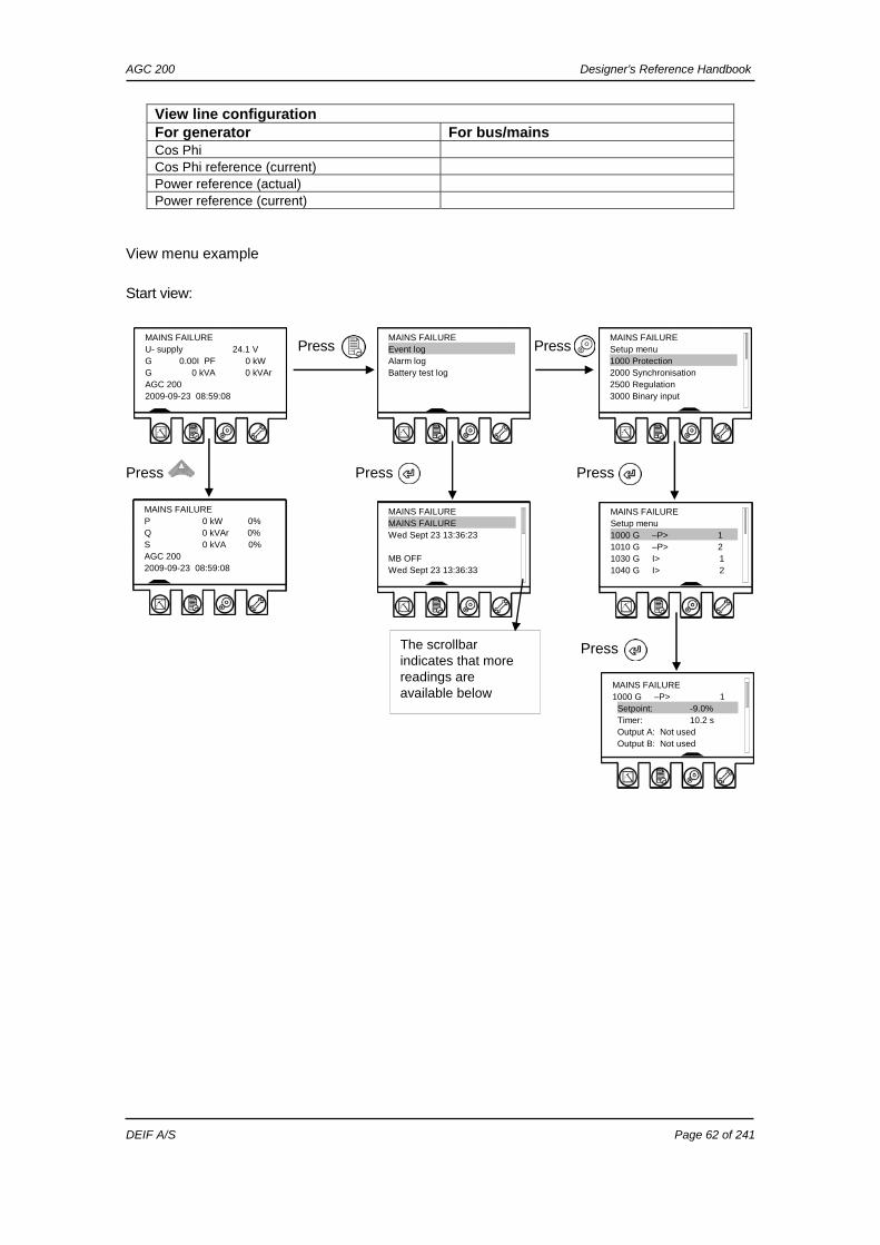
View menu example
Start view: Press Press
Press Press Press Press
The scrollbar indicates that more readings are available below
MAINS FAILURE U- supply 24.1 V G 0.00I PF 0 kW G 0 kVA 0 kVAr AGC 200 2009-09-23 08:59:08
MAINS FAILURE Event log . Alarm log Battery test log
MAINS FAILURE Setup menu 1000 G –P> 1 . 1010 G –P> 2 1030 G I> 1 1040 G I> 2
MAINS FAILURE 1000 G –P> 1 Setpoint: -9.0% . Timer: 10.2 s Output A: Not used Output B: Not used
AGC 200 Designer’s Reference Handbook
DEIF A/S Page 63 of 241
Mode overview The unit has four different running modes and one block mode. The modes are selected directly with push-buttons in the lower right corner of the unit front.
Auto
In auto mode, the unit will operate automatically and the operator cannot initiate any sequences manually.
Semi-auto
In semi-auto mode, the operator must initiate all sequences. This can be done via the push-button functions, Modbus commands or digital inputs. When started in semi-automatic mode, the genset will run at nominal values.
Test
The test sequence will start when the test mode is selected.
Manual
When manual mode is selected, the binary increase/decrease inputs can be used (if they have been configured) as well as the start and stop push-buttons. When starting in manual mode, the genset will start without any subsequent regulation.
OFF
When the OFF mode is selected, the unit is not able to initiate any sequences, e.g. the start sequence.
Password The unit includes three password levels. All levels can be adjusted in the PC software. Available password levels: Password level Factory setting Access
Customer Service Master Customer 2000 X Service 2001 X X Master 2002 X X X A parameter cannot be entered with a lower ranking password. But the settings can be displayed without password entry. Each parameter can be protected at a specific password level. To do so, the PC utility software must be used. Enter the parameter to be configured and select the correct password level.
OFF mode must be selected, when maintenance work is carried out on the genset.
AGC 200 Designer’s Reference Handbook
DEIF A/S Page 64 of 241
The password level can also be changed from the parameter view in the column Level.
Parameter access
To gain access to adjust the parameters, the password level must be entered:
AGC 200 Designer’s Reference Handbook
DEIF A/S Page 65 of 241
If the password level is not entered, it is not possible to enter the parameters.
The customer password can be changed in menu 9116. The service password can be changed in menu 9117. The master password can be changed in menu 9118.
The factory passwords must be changed if the operator of the genset is not allowed to change the parameters.
It is not possible to change the password at a higher level than the password entered.
AGC 200 Designer’s Reference Handbook
DEIF A/S Page 66 of 241
6. PID controller The unit controller is a PID controller. It consists of a proportional regulator, an integral regulator and a differential regulator. The PID controller is able to eliminate the regulation deviation and can easily be tuned in.
Controllers There are three controllers for the governor control and, if AVR control is selected, also three controllers for the AVR control.
Controller
GOV AVR Comment
Frequency X Controls the frequency Power X Controls the power P load sharing
X Controls the active power load sharing
Voltage X Controls the voltage VAr X Controls the power factor Q load sharing
X X Controls the reactive power load sharing
The table below indicates when each of the controllers is active. This means that the controllers can be tuned in when the shown running situations are present.
Governor AVR Schematic Frequency Power P
load sharing
Voltage VAr Q load
sharing
X
X
X
X
X
X
X X
G
GB MB
G
GB MB
G
GB MB
G
G
GB
GB
Please refer to the “General Guidelines for Commissioning”.
AGC 200 Designer’s Reference Handbook
DEIF A/S Page 67 of 241
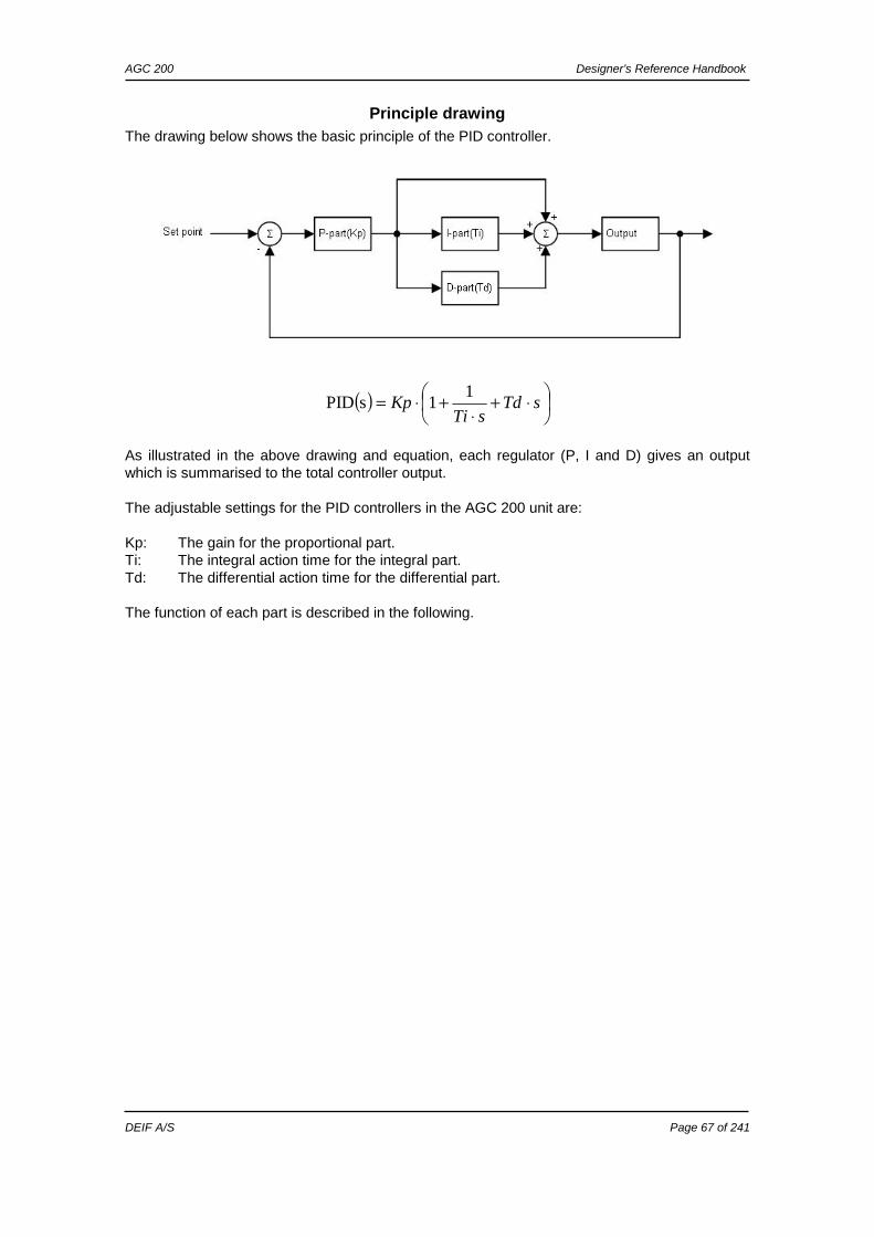
Principle drawing The drawing below shows the basic principle of the PID controller.
( ) ⎟⎠⎞
⎜⎝⎛ ⋅+
⋅+⋅= sTd
sTiKp
11sPID
As illustrated in the above drawing and equation, each regulator (P, I and D) gives an output which is summarised to the total controller output. The adjustable settings for the PID controllers in the AGC 200 unit are: Kp: The gain for the proportional part. Ti: The integral action time for the integral part. Td: The differential action time for the differential part. The function of each part is described in the following.
AGC 200 Designer’s Reference Handbook
DEIF A/S Page 68 of 241
Proportional regulator When the regulation deviation occurs, the proportional part will cause an immediate change of the output. The size of the change depends on the gain Kp. The diagram shows how the output of the P regulator depends on the Kp setting. The change of the output at a given Kp setting will be doubled, if the regulation deviation doubles.
Speed range
Because of the characteristic above, it is recommended to use the full range of the output to avoid an unstable regulation. If the output range used is too small, a small regulation deviation will cause a rather big output change. This is shown in the drawing below.
1% regulation deviation
20 80
% output
kP
40 100 60
kP
P regulator
0
20
40
60
80
100
0 10 20 30 40 50 60
Kp
Ou
tpu
t (%
)
4% 2%
1%
0.5%
AGC 200 Designer’s Reference Handbook
DEIF A/S Page 69 of 241
A 1% regulation deviation occurs. With the Kp setting adjusted, the deviation causes the output to change 20%. The table shows that the output of the AGC 200 changes relatively much if the maximum speed range is low.
Dynamic regulation area
The drawing below shows the dynamic regulation area at given values of Kp. The dynamic area will be smaller if the Kp is adjusted to a higher value.
Max. speed range
Output change Output change in % of max. speed range
50% 20% 20/50*100% 40 100% 20% 20/100*100% 20
Dynamic regulation band
-100
-75
-50
-25
0
25
50
75
100
44 45 46 47 48 49 50 51 52 53 54 55 56
Output [%]
Frequency [Hz]
Kp=50 Kp=10
Kp=1
AGC 200 Designer’s Reference Handbook
DEIF A/S Page 70 of 241
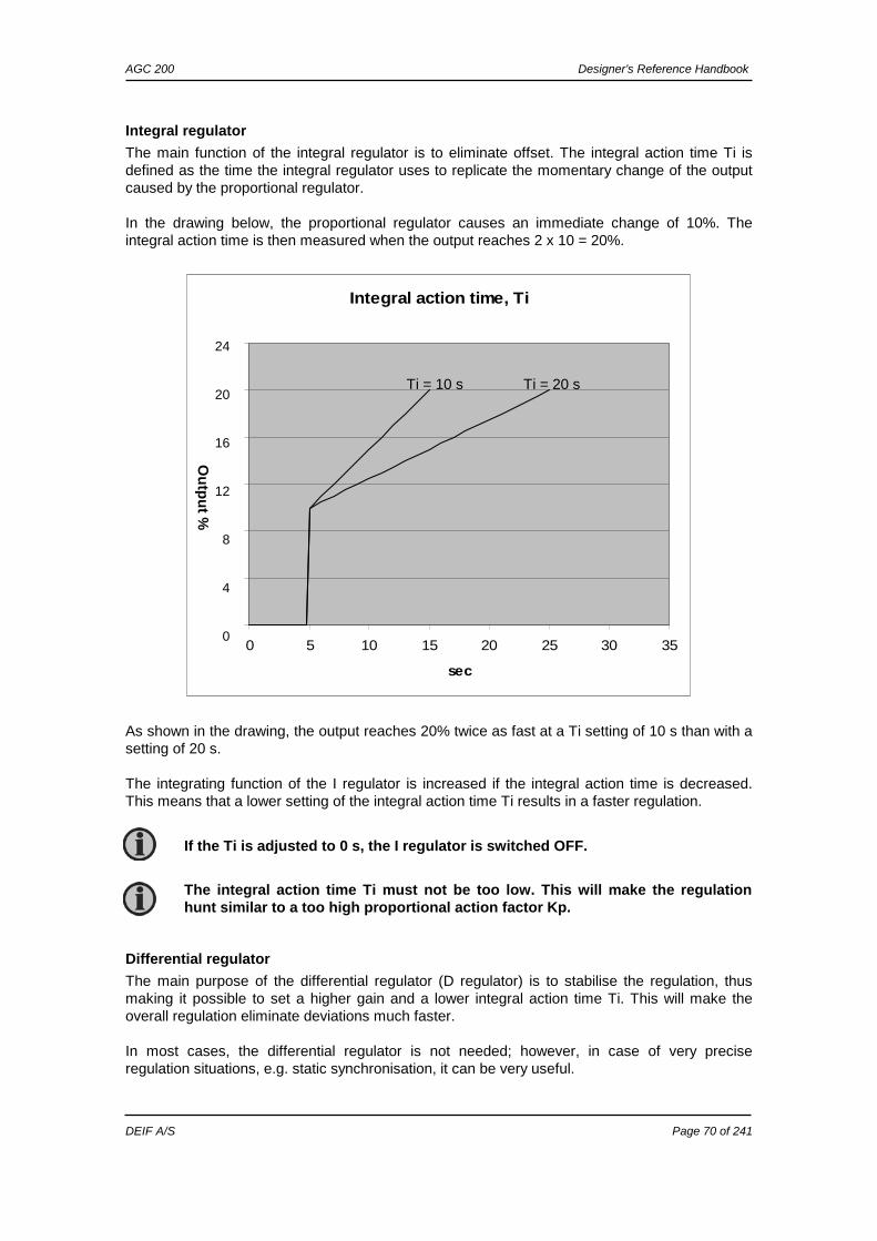
Integral regulator
The main function of the integral regulator is to eliminate offset. The integral action time Ti is defined as the time the integral regulator uses to replicate the momentary change of the output caused by the proportional regulator. In the drawing below, the proportional regulator causes an immediate change of 10%. The integral action time is then measured when the output reaches 2 x 10 = 20%. As shown in the drawing, the output reaches 20% twice as fast at a Ti setting of 10 s than with a setting of 20 s. The integrating function of the I regulator is increased if the integral action time is decreased. This means that a lower setting of the integral action time Ti results in a faster regulation.
Differential regulator
The main purpose of the differential regulator (D regulator) is to stabilise the regulation, thus making it possible to set a higher gain and a lower integral action time Ti. This will make the overall regulation eliminate deviations much faster. In most cases, the differential regulator is not needed; however, in case of very precise regulation situations, e.g. static synchronisation, it can be very useful.
The integral action time Ti must not be too low. This will make the regulation hunt similar to a too high proportional action factor Kp.
If the Ti is adjusted to 0 s, the I regulator is switched OFF.
Integral action time, Ti
0
1
2
3
4
5
6
0 5 10 15 20 25 30 35
sec
mA
Ti = 10 s Ti = 20 s
24
20
16
12
8
4
0
Ou
tpu
t %
AGC 200 Designer’s Reference Handbook
DEIF A/S Page 71 of 241
The output from the D regulator can be explained with the equation: dt
deKpTdD ⋅⋅=
D = Regulator output Kp = Gain de/dt = Slope of the deviation (how fast the deviation occurs) This means that the D regulator output depends on the slope of the deviation, the Kp and the Td setting. Example: In the following example, it is assumed that Kp = 1. Deviation 1: A deviation with a slope of 1. Deviation 2: A deviation with a slope of 2.5 (2.5 times bigger than deviation 1). D output 1, Td=0.5 s: Output from the D regulator when Td=0.5 s and the deviation is according
to Deviation 1. D output 2, Td=0.5 s: Output from the D regulator when Td=0.5 s and the deviation is according
to Deviation 2. D output 2, Td=1 s: Output from the D regulator when Td=1 s and the deviation is according
to Deviation 2. The example shows that the bigger the deviation and the higher the Td setting is, the bigger is the output from the D regulator. Since the D regulator is responding to the slope of the deviation, it also means that when there is no change, the D output will be zero.
The differential action time Td must not be too high. This will make the regulation hunt similar to a too high proportional action factor Kp.
If the Td is adjusted to 0 s, the D regulator is switched OFF.
When commissioning, please keep in mind that the Kp setting has influence on the D regulator output.
D-regulator
0
1
2
3
4
5
6
7
8
0 0,5 1 1,5 2 2,5
Time [s]
Ou
tpu
t/d
evia
tio
n
Deviation 2
D-output 2, Td=1sDeviation 1
D-output 2, Td=0.5 s
D-output 1, Td=0.5 s
AGC 200 Designer’s Reference Handbook
DEIF A/S Page 72 of 241
Load share controller/VAr share controller The load share controller and VAr share controller is used in the AGC 200 whenever load sharing/VAr sharing mode is activated. The controller is a PID controller similar to the other controllers in the system, and it handles frequency control as well as power control (load sharing) and voltage as well as reactive power control (VAr sharing).
Load share controller
Adjustment of the load share controller is done in menu 2540 (analogue control) or 2590 (relay control).
VAr share controller
Adjustment of the VAr share controller is done in menu 2660 (analogue control) or 2700 (relay control).
General
The primary purpose of the PID controllers is always frequency/voltage control because they are variable in a load sharing system, as well as the power/reactive power on the individual generator. Since the load sharing system requires power/reactive power regulation as well, the PID controllers can be affected by the power/reactive power regulator. For this purpose, a so-called weight factor is used (PWEIGHT/QWEIGHT). The regulation deviation from the power/reactive power regulator can therefore have great or less influence on the PID controller. An adjustment of 0% means that the power/reactive power control is switched off. An adjustment of 100% means that the power/reactive power regulation is not limited by the weight factor. Any adjustment in between is possible. The difference between adjusting the weight value to a high or low value is the speed at which the power/reactive power regulation deviation is eliminated. So if a firm load sharing is needed, the weight factor must be adjusted to a higher value than if an easy load sharing is required. An expected disadvantage of a high weight factor is that when a frequency/voltage deviation and a power/reactive power deviation exist, then hunting could be experienced. To avoid this, you can decrease either the weight factor or the parameters of the frequency/voltage regulator.
Synchronising controller The synchronising controller is used in the AGC 200 whenever synchronising is activated. After a successful synchronisation, the frequency controller is deactivated and the relevant controller is activated. This could e.g. be the load sharing controller. The adjustments are made in menu 2050. For synchronising, voltage matching is carried out using the voltage controller (setting 2640).
Dynamic synchronising
When dynamic synchronising is used, the controller ”2050 fSYNC controller” is used during the entire synchronising sequence. One of the advantages of dynamic synchronising is that it is relatively fast. In order to improve the speed of the synchronising further, the generator will be sped up between the points of synchronisation (12 o’clock to 12 o’clock) of the two systems. Normally, a slip frequency of 0.1 Hz gives synchronism each 10 seconds, but with this system on a steady engine, the time between synchronism is reduced.
Static synchronising
When synchronising is started, the synchronising controller ”2050 fSYNC controller” is activated and the generator frequency is controlled towards the busbar/mains frequency. The phase controller takes over when the frequency deviation is so small that the phase angle can be controlled. The phase controller is adjusted in menu 2070 (”2070 phase controller”).
AGC 200 Designer’s Reference Handbook
DEIF A/S Page 73 of 241
Relay control When the relay outputs are used for control purposes, the regulation works like this:
The regulation with relays can be split up into five steps. # Range Description Comment 1 Static range Fix up signal The regulation is active, but the increase relay will be
constantly activated because of the size of the regulation deviation.
2 Dynamic range
Up pulse The regulation is active, and the increase relay will be pulsing in order to eliminate the regulation deviation.
3 Dead band area
No reg. In this particular range, no regulation takes place. The regulation accepts a predefined dead band area in order to increase the lifetime of the relays.
4 Dynamic range
Down pulse The regulation is active, and the decrease relay will be pulsing in order to eliminate the regulation deviation.
5 Static range Fix down signal The regulation is active, but the decrease relay will be constantly activated because of the size of the regulation deviation.
As the drawing indicates, the relays will be fixed ON if the regulation deviation is big, and they will be pulsing if it is closer to the setpoint. In the dynamic range, the pulses get shorter and shorter when the regulation deviation gets smaller. Just before the dead band area, the pulse is as short as it can get. This is the adjusted time ”GOV ON time”/(”AVR ON time”). The longest pulse will appear at the end of the dynamic range (45 Hz in the example above).
55 Hz 45 Hz 50 Hz
Regulator output
Fix up signal Up pulse No reg. Fix down signal Down pulse
Hz
AGC 200 Designer’s Reference Handbook
DEIF A/S Page 74 of 241
Relay adjustments
The time settings for the regulation relays can be adjusted in the control setup. It is possible to adjust the ”period time” and the ”ON time”. They are shown in the drawing below. Adjustment Description Comment Period time Maximum relay time The time between the beginnings of two
subsequent relay pulses. ON time Minimum relay time The minimum length of the relay pulse. The
relays will never be activated for a shorter time than the ON time.
As it is indicated in the drawing below, the length of the relay pulse will depend on the actual regulation deviation. If the deviation is big, then the pulses will be long (or a continued signal). If the deviation is small, then the pulses will be short.
ON ON ON ON ON
PERIOD PERIOD PERIOD PERIOD PERIOD
t [sec]
Relay ON
HIGH <DEVIATION> LOW
AGC 200 Designer’s Reference Handbook
DEIF A/S Page 75 of 241
Signal length
The signal length is calculated compared to the adjusted period time. In the drawing below, the effect of the proportional regulator is indicated.
In this example, we have a 2 percent regulation deviation and an adjusted value of the Kp = 20. The calculated regulator value of the unit is 40%. Now, the pulse length can be calculated with a period time = 2500 ms: The length of the period time will never be shorter than the adjusted ON time.
Regulation failure
The governor/AVR regulation failure in menu 2560/2680 occurs when the regulation is activated but the setpoint cannot be reached. The alarm will appear when the setpoint is reached. The deviation is calculated in percent:
Example:
UACTUAL = 400V AC UNOMINAL = 440V AC Difference in percent: (440-400)/440*100 = 9.1% If the alarm setting is lower than 9.1% in this example, the alarm appears.
P regulator
0
20
40
60
80
100
0 10 20 30 40 50 60
Kp
Ou
tpu
t (%
)
4% 2%
1%
0.5%
ms
te PERIODDEVIATION
10002500*100/40
*100/
=
Adjust the alarm setting ”Dead band” to 100% to deactivate the alarm.
AGC 200 Designer’s Reference Handbook
DEIF A/S Page 76 of 241
7. Synchronisation The unit can be used for synchronisation of generator and mains breaker (if installed). Two different synchronisation principles are available, namely static and dynamic synchronisation (dynamic is selected by default). This chapter describes the principles of the synchronisation functions and the adjustment of these.
Dynamic synchronisation In dynamic synchronisation, the synchronising genset is running at a different speed than the generator on the busbar. This speed difference is called slip frequency. Typically, the synchronising genset is running with a positive slip frequency. This means that it is running with a higher speed than the generator on the busbar. The objective is to avoid a reverse power trip after the synchronisation. The dynamic principle is illustrated below.
In the following, the term “synchronisation” means “synchronising and closing of the synchronised breaker”.
AGC 200 Designer’s Reference Handbook
DEIF A/S Page 77 of 241
In the example above, the synchronising genset is running at 1503 RPM ~ 50.1 Hz. The generator on load is running at 1500 RPM ~ 50.0 Hz. This gives the synchronising genset a positive slip frequency of 0.1 Hz. The intention of the synchronising is to decrease the phase angle difference between the two rotating systems. These two systems are the three-phase system of the generator and the three-phase system of the busbar. In the illustration above, phase L1 of the busbar is always pointing at 12 o’clock, whereas phase L1 of the synchronising genset is pointing in different directions due to the slip frequency. When the generator is running with a positive slip frequency of 0.1 Hz compared to the busbar, then the two systems will be synchronised every 10 seconds. In the illustration above, the difference in the phase angle between the synchronising set and the busbar gets smaller and will eventually be zero. Then the genset is synchronised to the busbar, and the breaker will be closed.
Close signal
The unit always calculates when to close the breaker to get the most accurate synchronisation. This means that the close breaker signal is actually issued before being synchronised (read L1 phases exactly at 12 o’clock). The breaker close signal will be issued depending on the breaker closing time and the slip frequency (response time of the circuit breaker is 250 ms, and the slip frequency is 0.1 Hz): The length of the synchronisation pulse is the response time + 20 ms (2020 Synchronisation).
Load picture after synchronising
When the incoming genset has closed its breaker, it will take a portion of the load depending on the actual position of the fuel rack. Illustration 1 below indicates that at a given positive slip frequency, the incoming genset will export power to the load. Illustration 2 below shows that at a given negative slip frequency, the incoming genset will receive power from the original genset. This phenomenon is called reverse power.
Of course, both three-phase systems are rotating, but for illustrative purposes the vectors for the generator on load are not shown to be rotating. This is because we are only interested in the slip frequency for calculating when to release the synchronisation pulse.
sec100.501.50
1 =−
=SYNCt
deg9deg
1.0*250.0*360deg
**360deg
===
CLOSE
CLOSE
SLIPCBCLOSE ft
The synchronisation pulse is always issued, so the closing of the breaker will occur at the 12 o’clock position.
Please refer to the chapter regarding PID controllers and the synchronising controllers on page 72 regarding the time between synchronism.
AGC 200 Designer’s Reference Handbook
DEIF A/S Page 78 of 241
Illustration 1, POSITIVE slip frequency
Illustration 2, NEGATIVE slip frequency
Adjustments
The dynamic synchroniser is selected in menu 2000 Synchronisation type. The control setup is adjusted in 2020 Synchronisation. Setting Description Comment 2021 fMAX Maximum slip frequency Adjust the maximum positive slip frequency where
synchronising is allowed. 2022 fMIN Minimum slip frequency Adjust the maximum negative slip frequency where
synchronising is allowed. 2023 UMAX Maximum voltage differen-
ce (+/- value) The maximum allowed voltage difference between the busbar/mains and the generator.
2024 tGB Generator breaker closing time
Adjust the response time of the generator breaker.
2025 tMB Mains breaker closing time Adjust the response time of the mains breaker.
0% 100%
PGen2
FUEL INDEX
FUEL INDEX
0% 100%
G1
G2 GB
GB
LOAD
PGen1
Reverse power
0% 100%
PGen2
FUEL INDEX
FUEL INDEX
0% 100%
G1
G2 GB
GB
LOAD
PGen1
To avoid nuisance trips caused by reverse power, the synchronising settings can be set up with a positive slip frequency.
AGC 200 Designer’s Reference Handbook
DEIF A/S Page 79 of 241
It is obvious that this type of synchronisation is able to synchronise relatively fast because of the adjusted minimum and maximum slip frequencies. This actually means that when the unit is aiming to control the frequency towards its setpoint, then synchronising can still occur as long as the frequency is within the limits of the slip frequency adjustments.
Static synchronisation In static synchronisation, the synchronising genset is running very close to the same speed as the generator on the busbar. The aim is to let them run at exactly the same speed and with the phase angles between the three-phase system of the generator and the three-phase system of the busbar matching exactly. The static principle is illustrated below.
Dynamic synchronisation is recommended where fast synchronisation is required, and where the incoming gensets are able to take load just after the breaker has been closed.
It is not recommended to use the static synchronisation principle when relay regulation outputs are used. This is due to the slower nature of the regulation with relay outputs.
AGC 200 Designer’s Reference Handbook
DEIF A/S Page 80 of 241
Phase controller
When the static synchronisation is used and the synchronising is activated, the frequency controller will bring the genset frequency towards the busbar frequency. When the genset frequency is within 50 mHz of the busbar frequency, then the phase controller takes over. This controller uses the angle difference between the generator system and the busbar system as the controlling parameter. This is illustrated in the example above, where the phase controller brings the phase angle from 30 deg. to 0 deg.
Close signal
The close signal will be issued when phase L1 of the synchronising generator is close to the 12 o’clock position compared to the busbar, which is also in 12 o’clock position. It is not relevant to use the response time of the circuit breaker when using static synchronisation, because the slip frequency is either very small or non-existing. To be able to get a faster synchronisation, a ”close window” can be adjusted. The close signal can be issued when the phase angle UGENL1-UBBL1 is within the adjusted setpoint. The range is +/-0.1-20.0 deg. This is illustrated in the drawing below.
The synchronisation pulse is sent dependent on the settings in menu 2030. It depends on whether it is the GB or the MB that is to be synchronised.
Load picture after synchronisation
The synchronised genset will not be exposed to an immediate load after the breaker closure if the maximum df setting is adjusted to a low value. Since the fuel rack position almost exactly equals what is required to run at the busbar frequency, no load jump will occur. If the maximum df setting is adjusted to a high value, then the section about ”dynamic synchronisation” must be observed.
Max. dU difference
Max. dU difference Direction of
rotation
+/- close window
UBB
UGEN
AGC 200 Designer’s Reference Handbook
DEIF A/S Page 81 of 241
After the synchronising, the unit will change the controller setpoint according to the requirements of the selected genset mode.
Adjustments
The following settings must be adjusted if the static synchroniser is selected in menu 2000: Setting Description Comment 2031 Maximum df
The maximum allowed frequency difference between the busbar/mains and the generator.
+/- value.
2032 Maximum dU
The maximum allowed voltage difference between the busbar/mains and the generator.
+/- value related to the nominal generator voltage.
2033 Closing window
The size of the window where the synchronisation pulse can be released.
+/- value.
2034 Static sync
Minimum time inside the phase window before sending a close command.
2035 Static type GB
“Breaker” or “Infinite sync” can be chosen. “Infinite sync” will close the MB to the busbar and run the generator in sync with the mains. The GB is not allowed to close.
2036 Static type MB
“Breaker” or “Infinite sync” can be chosen. “Infinite sync” will close the GB to the busbar and run the generator in sync with the mains. The MB is not allowed to close.
2061 Phase KP
Adjustment of the proportional factor of the PI phase controller.
Only used during analogue regulation output.
2062 Phase KI
Adjustment of the integral factor of the PI phase controller.
2070 Phase KP
Adjustment of the proportional factor of the PI phase controller.
Only used during relay regulation output.
GB closing before excitation It is possible to adjust the AGC 200 to start up the genset with the excitation switched off. When the gensets are started up, the breakers will be closed and the excitation started. It is also possible to close the breaker before the engine is started. This function is called ”close before excitation”. The purpose of the ”close before excitation” is to enable the gensets to be ready for the load very quickly. All of the gensets will be connected to the busbar as soon as they are started, and as soon as the excitation is switched on, the gensets are ready for operation. This is faster than the normal synchronising, because in that case the breakers will not be closed until the generator voltage is in the synchronised position, and it takes some time to achieve that position. The ”close before start” function can also be used if the load requires a ”soft” start. This can be the case when the gensets connect to a transformer. As soon as the excitation is activated, the generators will equalise the voltage and frequency and will eventually run in a synchronised system. When the excitation is activated, the regulators of
Static synchronisation is recommended where a slip frequency is not accepted, for instance if several gensets synchronise to a busbar with no load groups connected.
AGC 200 Designer’s Reference Handbook
DEIF A/S Page 82 of 241
the AGC 200 will be switched on after an adjustable delay. The function can be used in the single AGC 200, but also the AGC 200 with option G4 or G5. The principle is described in the following flowcharts.
Flowchart abbreviations
Delay 1 = Menu 2252 Delay 2 = Menu 2262 Delay 3 = Menu 2271 SP1 = Menu 2251 SP2 = Menu 2263
The excitation must be increased slowly when this function is used.
This function can only be used when a magnetic pick-up is used.
AGC 200 Designer’s Reference Handbook
DEIF A/S Page 83 of 241
Flowchart 1, GB handling
Start excitation
Delay 2 expired
Delay 3 expired
"Close before excitation"
failure
Activate regulators
Yes
Yes
UBUS OK
END
Delay 3 expired
"Close before excitation"
failure
No
Yes
UBUS OK
Yes
No
RPM > SP1Delay 1 expired
Close GB
RPM > SP2
Delay 1 expired Trip GB
Yes
No Yes
Delay 1 expired on all DG(s)
Start excitation
Yes
Yes
Delay 2 expired
Activate regulators
Yes
Sync GB
No
Yes
Yes
No
No
No
No
No
No
START
Start DG(s)
No
AGC 200 Designer’s Reference Handbook
DEIF A/S Page 84 of 241
Flowchart 2, TB handling (AGC 244 only)
Any GB closed
PAVAIL > PCAP
"GB + TB"
MB OFF
Sync TBClose TB
Yes
Yes
Yes
Yes
No
No
TB Open
Yes
END
No
START
No
No
AGC 200 Designer’s Reference Handbook
DEIF A/S Page 85 of 241
Genset start actions
The start sequence of the AGC 200 is changed in order to achieve the function ”close before excitation”. The following parameters must be adjusted: Menu Description Comment 2251 RPM setpoint for
breaker closing The generator breaker will close at the adjusted level. The range is from 0-400 RPM. If it is adjusted to 0, the breaker will be closed when the start command is given. In the example below, the setting is adjusted to 400.
2252 RPM timer The genset must reach the setpoint (menu 2263) within the adjusted delay. When the delay expires and the RPM is above the setpoint, the excitation will be started. If the RPM is below the setpoint, the GB will be tripped.
2253 Output A Select the relay output that must be used to start the excitation. Configure the relay to be a limit relay in the I/O setup.
2255 Enable Enable the function ”close before excitation”. The diagram above shows that the GB will be closed at 400 RPM. When the engine RPM has reached the setpoint (menu 2263) (1450 RPM), the excitation is switched on.
Breaker sequence
The “GB close before start” function can be used in three applications:
1. AGC 200 single genset plant. 2. AGC 200 power management plant - no tie breaker present. 3. AGC 200 power management plant - tie breaker present.
In one of the applications, a tie breaker is present, and it must be adjusted in the menu 2261 whether only the generator breaker must be closed or both the generator breaker and the tie breaker.
1500 RPM
1350 RPM
400 RPM
Engine RPM
time
Close GB Start
excitation
RPMNOM
AGC 200 Designer’s Reference Handbook
DEIF A/S Page 86 of 241
The breaker sequence adjustments are the following:
Menu Description Comment 2261 Breaker selection Select breakers to close: GB or GB + TB. 2262 Timer The timer defines the period from the excitation is started and
until the regulation is activated. The alarms with inhibit set to ”Not run status” will be activated after this timer has expired.
2263 Excitation start level The setting defines at what level of RPM the excitation is started.
”Close before excitation” failure
If starting of the genset is not successful, the alarm menu 2270 ”Cl.bef.exc.fail” will occur, and the selected fail class will be executed.
Separate synchronising relay When the AGC 200 gives the synchronising command, the relays on terminal 17/18/19 (generator breaker) and terminal 11/12/13 (mains breaker) will activate, and the breaker must close when this relay output is activated. This default function can be modified using a digital input and extra relay outputs depending on the required function. The relay selection is made in menu 2240, and the input is selected in the input settings in the utility software. The table below describes the possibilities.
Relay Input
Relay selected Two relays used
Relay not selected One relay used
Not used Synchronising: The breaker ON relay and the sync. relay activate at the same time when synchronising is OK. Blackout closing: The breaker ON relay and the sync. relay activate at the same time when the voltage and frequency are OK.
Synchronising: The breaker ON relay activates when synchronising is OK. Blackout closing: The breaker ON relay activates when the voltage and frequency are OK. DEFAULT selection
Low Synchronising: Not possible. Blackout closing: The breaker ON relay and the sync. relay activate at the same time when the voltage and frequency are OK.
Synchronising: Not possible. Blackout closing: The breaker ON relay activates when the voltage and frequency are OK.
High Synchronising: The relays will activate in two steps when the synchronising is selected:
1. Breaker ON relay activates. 2. When synchronised, the sync.
relay activates. See note below! Blackout closing: The breaker ON relay and the sync. relay activate at the same time when the voltage and frequency are OK.
Synchronising: Not possible. Blackout closing: The breaker ON relay activates when the voltage and frequency are OK.
AGC 200 Designer’s Reference Handbook
DEIF A/S Page 87 of 241
When two relays are used together with the separate sync. input, then please notice that the breaker ON relay will be activated as soon as the GB ON/synchronising sequence is activated. Care must be taken that the GB ON relay cannot close the breaker, before the sync. signal is issued by the sync. relay.
The selected relay for this function must have the ”limit” function. This is adjusted in the I/O setup.
AGC 200 Designer’s Reference Handbook
DEIF A/S Page 88 of 241
8. Engine communication This function gives the possibility of communication between ML-2 and several engine types over the CANbus. AVR control is possible for selected digital voltage regulators.
Modbus communication If option H2 is present, it is possible to read engine data over the Modbus.
Wiring
Principle diagram
For wiring details, please refer to the document ”Installation Instructions”.
Please refer to the document ”Description of option H2”.
Generator set
ECM module
Option H2
PLC (or computer), AMS (Alarm- and Monitoring System)
Display
Option H5
AGC 200
AGC 200 Designer’s Reference Handbook
DEIF A/S Page 89 of 241
Functional description This communication extracts information from the Electronic Control Module (ECM) of an engine equipped with an ECM module with CANbus interface. The values can be used as display values, alarms/shutdown alarms and values to be transmitted through Modbus.
Engine types
Data can be transmitted between the ML-2 units and the following engine controllers/types: Engine manu-facturer
Engine controller/type Comment
Caterpillar ADEM III and A4/C4.4, C6.6, C9, C15, C18, C32 Rx/Tx
Cummins CM570 and CM850/QSL, QSB5 and 7, QSM11, QSK19, 50 and 60
Rx/Tx
Detroit Diesel DDEC III and IV/Series 50, 60 and 2000 Rx/Tx
Iveco EDC7 (Bosch MS6.2)/Series NEF, CURSOR and VECTOR 8
Rx/Tx
John Deere JDEC/PowerTech M, E and Plus Rx/Tx
MTU MDEC, module M.302 or M.303/Series 2000 and 4000 Rx
MTU MDEC, module M.201 or M.304/Series 2000 and 4000 Rx
Select M.303
MTU ADEC/Series 2000 and 4000 (ECU 7) Rx/Tx
MTU J1939 Smart Connect/Series 1600 (ECU 8) Rx/Tx
Perkins Series 1100, 1300, 2300, 2500 and 2800 Rx/Tx
Scania EMS Rx
Scania EMS S6 (KWP2000)/Dx9x, Dx12x, Dx16x Rx/Tx
Volvo Penta EDC4
Rx
Select EMR 2
Volvo Penta EMS Rx
Volvo Penta EMS 2 and EDCIII/D6, D7, D9, D12 and D16 (GE and AUX variants only)
Rx/Tx
The engine type is selected in menu 7561.
For support of controller/engine types not listed, please contact DEIF A/S.
Rx/Tx: Please refer to the section ”Specific engine type descriptions” for details of data read and write.
AGC 200 Designer’s Reference Handbook
DEIF A/S Page 90 of 241
AVR types
Data can be transmitted between the ML-2 units and the following AVRs: Engine manufacturer AVR type Comment
Caterpillar CDVR Tx
Communication system
All these protocols are based on a CANbus communication system. Except for the MDEC and ADEC communication, they are all based on the J1939. The MDEC and ADEC protocols are MTU designed protocols based on CANopen. The Baud rate is fixed by the engine manufacturer at: MDEC, ADEC Caterpillar, Cummins, Detroit Diesel, Deutz, Iveco, John Deere,
Perkins, MTU J1939 Smart Connect, Scania and Volvo Penta
125 kb/s 250 kb/s
EIC unit
The selection of the EIC unit (menu 10970) determines whether bar/PSI or Celsius/Fahrenheit is used. The selection affects display readings, values used for alarm evaluation (menu 76xx) and data readable by Modbus communication (option H2).
Common for all alarm functions
A number of alarms can be configured. The following items can be configured to an alarm:
Menu number Alarm Comment
7570 EI comm. error Communication error.
7580 EIC warning Any alarm listed as warning for the selected engine type in the section ”Specific engine type descriptions”.
7590 EIC shutdown
Any alarm listed as shutdown for the selected engine type in the section ”Specific engine type descriptions”.
7600 EIC overspeed Actual RPM.
7610/7620 EIC coolant t. (2 levels) Actual temperature.
7630/7640 EIC oil press. (2 levels) Actual pressure.
7650/7660 EIC oil temp. (2 levels) Actual temperature.
7670/7680 EIC coolant level (2 levels) Actual cooling water level
AGC 200 Designer’s Reference Handbook
DEIF A/S Page 91 of 241
J1939 measurement table
This is the common J1939 measurement overview, showing which measurements are available. Please notice that not all measurements are supported by the individual engines; please refer to the specific engine description. The display values corresponding to the engine communication have a description beginning with ”EIC”.
Error messages
The following error messages can occur: Message Description
Engine I. value N.A. The view is not selectable for the present engine type.
Value selected error The value cannot be read due to sensor error, sub-system or module error.
”N.A.” The value is not supported by the engine, or there is a communication error.
The table shows which values can be displayed in the view menu. The values must be selected in the views setting of the PC utility software.
AGC 200 Designer’s Reference Handbook
DEIF A/S Page 92 of 241
Object selection, J1939
The view lines can be configured with these available values.
EIC engine trip fuel 65257 6 1 4 182 L 0.5 L/bit, offset 0 EIC engine total fuel used 65257 6 5 4 250 L 0.5 L/bit, offset 0 EIC Nominal Power 65214 7 1 2 166 kW 0.5 kW/bit EIC Mean trip fuel consumption
65203 7 5 2 1029 l/h 0.05[l/h]/bit
EIC Intake Manifold #1 absolute pressure
64976 6 5 1 3563 Bar or psi
2 kPa/bit
For the Iveco Vector 8 type only: (*1): EIC coolant temp.: PGN=65282, priority=6, start at byte 5, length=1byte, SPN=110, same
scale. (*3): EIC oil temp.: PGN=65282, priority=6, start at byte 6, length=1byte, SPN=175, same
scale. (*2): EIC oil pressure. PGN=65282, priority=6, start at byte 7, length=1byte, 8 kPa/bit gain, 0
kPa offset, data range: 0 to +2000 kPa.
Show engine values in display unit It is possible to parameterise the AGC so all analogue values from the engine CANbus is shown in the display unit. This is an example where speed, inlet air and coolant temp. is shown. The number of available views is 20 views. The number can be increased with the auto view function. The AGC is set up in one of two ways:
1. Use the function of the PC Utility SW: “configuration of the user views”. In this way, the 20 three-line views can be configured to show the desired. A total of 20 views is displayed (unless fewer is set up).
The objects are not supported by all engines. Please refer to the specific engine type manual for information about the specific engine.
The Modbus addresses are read only (function code 04h) and are only available if option H2 (Modbus RTU) is implemented.
ISLAND AUTO EIC Speed 1500 rpm EIC coolant t 81 C EIC t. Air Inlet 35 C Energy Total 0 kWh Run Absolute 0 hrs
AGC 200 Designer’s Reference Handbook
DEIF A/S Page 94 of 241
2. Use the auto view function in the communication setup. (Menu number 7564.) In this way, the 20 three-line views are kept with their present setup and all engine values are added to the list of the 20 three-line views. A total of 20+14 three-line views are available. The 20 lines are user-configurable but the 14 additional lines are dedicated to EIC values and cannot be modified by the user.
The first option is useful when a few EIC values need to be shown and if all off the 20 user- configurable views are not already used to display requested values. The second option is useful if it is requested to read all available EIC data from the ECU. It must be noted that all available data is shown when using this method until the additional 14 views are used. The number of extra display views depends on the available data from the specific engine controller connected to the controller.
Configuration of user views
This is done from the PC utility SW by choosing the user view icon in the settings menu (or on the horizontal toolbar):
Activation of auto views
The extra view lines are displayed if the menu 7564 is switched to ON and the engine CANbus is active. (It might be necessary to start the engine before switching 7564 to ON). The setting automatically returns to OFF. To de-activate the auto view function, please follow these steps:
1. Adjust Engine IF type to OFF (menu 7561) 2. Adjust EIC AUTOVIEW to ON (menu 7564) 3. Adjust EIC AUTOVIEW to OFF (menu 7564)
(the menu is not reset automatically when no engine is selected)
AGC 200 Designer’s Reference Handbook
DEIF A/S Page 95 of 241
Verification of J1939 objects
To verify the communication, various CAN PC tools can be used. Common for these is that they must be connected to the CANbus between the Multi-line 2 unit and the engine controller. When the tool is connected, it is possible to monitor the communication between the two units. For use of the CAN tool, please refer to the manual for the product used. As an example, you can see the following telegram: 0xcf00400 ff 7d 7d e0 15 ff f0 ff DATA BYTE: 1 2 3 4 5 6 7 8
- 0xc is the priority. - f004 is the PGN number (61444 in decimal value). - The eight bytes following the CAN ID (0xcf00400) are data, starting with byte 1.
The priority needs to be converted to decimal. Please notice that the three priority bits in this case are displayed in the CAN ID (you read 0xcf00400 instead of 0x0cf00400). In other cases, you may read e.g. 0x18fef200 (PGN 65266). The formula to find the priority number (P) is to divide by 4: 0xc = 12 (Dec) => Priority 3 Priority DecID HexID 1 4d 0x4 2 8d 0x8 3 12d 0xc 4 16d 0x10 5 20d 0x14 6 24d 0x18 Normally in SAE J1939, only priority 3 and 6 are used. Hereafter the data can be read (PGN 61444): 0xcf00400 xD ff 7d 7d e0 15 ff f0 ff Engine torque (Data byte 1) ff Not available Driver demand torque (Data byte 2) 7d Actual engine torque (Data byte 3) 7d Engine speed (Data byte 4) e0 Engine speed (Data byte 5) 15 Source address (Data byte 6) ff Not available Engine starter mode (Data byte 7) f0 Engine demand (Data byte 8) ff Not available Calculation example: RPM resolution is 0.125 RPM/bit, offset 0. The result is then 15e0 (Hex) or 5600 (dec)*0.125 = 700 RPM.
AGC 200 Designer’s Reference Handbook
DEIF A/S Page 96 of 241
Displaying of J1939 DM1/DM2, Scania KWP2000 and Caterpillar/Perkins alarms
Besides some engine specific alarms, which are shown in the standard alarm list, the J1939 diagnostic messages DM1 (active alarms) and DM2 (historic alarm log list) as well as the Scania KWP 2000 alarms can all be shown on the display. In both cases, the alarms are accessed through the LOG list. Press to enter the list:
Use the and buttons to scroll through the list, and select the alarm log you wish to see by pressing . For DM1 and DM2, the SPN (Suspect Parameter Number) and FMI (Failure Mode Indicator) will be shown along with a clear text. In the DM2 list, if you wish to acknowledge, the entire alarm log list will be cleared. For safety reasons, this requires the master password (please see the password description in this document for details of passwords).
Scania KWP 2000
The Scania KWP 2000 log shows active and passive alarms in a mix.
Use the and buttons to scroll through the list. If you acknowledge, the entire alarm log list will be cleared. For safety reasons, this requires the master password (please see the password description in this document for details of passwords). Caterpillar/Perkins Press the LOG button for 2 seconds. That will bring the alarm log on the display. Caterpillar and Perkins have a primary and a secondary DM1 log as well as one DM2 log. The primary DM1 log shows alarms from the ADEM III/IV engine controllers. The secondary DM1 log shows alarms from the EMCP 3.x genset controller. Similar to the J1939 protocol, the
DM2 log shows the historical alarms. Use the and buttons to scroll through the list. CLRALL: By pressing ENTER, the entire alarm log list will be cleared. For safety reasons, this requires the master password (please see the “Designer’s Reference Handbook” for details of passwords).
If the controller has no translation text of an SPN diagnostic number, “Text N/A.” will be shown. For information about particular SPN numbers, please consult the engine manufacturer’s documentation or SAE J1939-71 for a general description.
AGC 200 Designer’s Reference Handbook
DEIF A/S Page 97 of 241
Control commands sent to the engine Engine types with the possibility to send commands to the ECM via the CANbus communication line:
Engine type
Command
Detro
it Diesel D
DE
C
Joh
n D
eere JDE
C
Caterp
illar
Perkin
s
Cu
mm
ins
Gen
eric J1939
Deu
tz EM
R
Iveco
Iveco, V
ector 8
MT
U M
DE
C
MT
U A
DE
C
MT
U J1939 sm
art c
Scan
ia EM
S
Scan
ia EM
S S
6
Vo
lvo P
enta
Vo
lvo P
enta E
MS
2
Preheat - - - - - - - - - - - - - - - X Start/stop - - X X - - - - - - X X - X - X Engine speed
X X X X X X X X X - X X - X - X
Nominal frequency
- - - - X - - - - X X - X - X
Governor gain
- - - - X - - - - - - - - - - -
Idle speed
X X X X X X X X - - X X - X - X
Droop - - - X X - - - - - X X - X - X Shutdown override
- - - - X - - - - - - X - X - X
Engine over-speed test
- - - - - - - - - - - X - - - -
Enable Cylinder Cutout
- - - - - - - - - - X X - - - -
Inter-mittent oil priming
- - - - - - - - - - - X - - - -
Engine operating mode
- - - - - - - - - - - X - - - -
Demand Switch
- - - - - - - - - - X X - - - -
Trip counter reset
- - - - - - - - - - X X - - - -
Engine speed gov param command
- - - - - - - - - - - X - - - -
For engine types not mentioned, CANbus control is not supported. In these cases, start/stop etc. must be sent to the controller using hardwired connections.
The menu number 7563 must be used to enable or disable the transmission of all the Multi-line 2 unit EIC control frames listed in the above table.
AGC 200 Designer’s Reference Handbook
DEIF A/S Page 98 of 241
EIC 50 Hz – 60 Hz switch If the setpoint fNOMINAL is changed on the AGC between 50 and 60 Hz, then the change is made with a frequency ramp of 2 Hz per seconds. This frequency ramp is used when switching between nominal settings 1-4 or if the parameter of the nominal frequency is changed between 50 and 60 Hz.
EIC droop There are two ways of obtaining a speed droop: For engines where the droop command or setpoint can be sent to the engine controller, the DROOP setting in parameter 2771 is the actual droop that is being used, and this setpoint is sent to the ECU. This method is referred to as “EIC droop”. For engines where the droop command or setpoint cannot be sent to the engine controller, the DROOP setting in parameter 2771 is used for droop emulation in the AGC 200. This method is known as “EIC droop emulation”. In both cases, the DROOP function is activated in the M-Logic (EIC droop/EIC droop emulation) command output. Please refer to the specific engine type to determine if droop is supported or whether emulated droop has to be used.
EIC inhibit The EIC alarms can be inhibited through M-Logic. This would typically be necessary during stopping of the engine. The following alarms are inhibited by this command:
EIC Idle The “Idle function” of the AGC is activated in the menu 6290. If this is used with engines with speed control from CANbus communication, the speed is defined to be 600 rpm.
Specific engine type descriptions
The J1939 warnings/shutdowns with corresponding SPN and FMI numbers in this chapter refer to those that will automatically appear in the alarm list. The alarms can be acknowledged from the display. The available alarms vary from engine type to engine type. Besides these, the entire log list can be read in the engine controller by pressing the ”LOG” button for three seconds.
AGC 200 Designer’s Reference Handbook
DEIF A/S Page 99 of 241
Caterpillar/Perkins (J1939)
Warnings and shutdowns
Warning/shutdown list J1939 codes
SPN
FMI warning
FMI shutdown
Low oil pressure 100 17 1
Intake manifold #1 P 102 15 -
Coolant temperature 110 15 1
High inlet air temp. 172 15 -
Fuel temperature 174 15 -
Overspeed 190 15 0
EIC yellow lamp - X -
EIC red lamp - - X
EIC malfunction - X -
EIC protection - X -
Write commands to engine controller
• Engine controls
All the write commands to the engine controller (e.g. speed, start/stop, etc.) are enabled in setting 7563 (EIC controls).
• Engine speed CANbus ID for speed control: 0x0c000000. J1939 TSC1. M-Logic commands are available to enable/disable start/stop and speed controls:
o EIC start/stop enable o EIC speed control inhibit
Write commands to AVR
• AVR controls All the write commands to the AVR (voltage control) are enabled in setting 7563 (EIC controls). If engine controls are needed but not the AVR control, the latter can be disabled through menu 7565.
The speed regulation is enabled in setting 2781 (Reg. output) and 7563 (EIC controls).
FMI indication “–“ means that the alarm in question is not supported.
AGC 200 Designer’s Reference Handbook
DEIF A/S Page 100 of 241
Cummins CM850-CM570 (J1939)
Warnings and shutdowns
Warning/shutdown list J1939 codes
SPN
FMI warning
FMI shutdown
Low oil pressure 100 18 1
Coolant temperature 110 16 0
Oil temperature 175 16 0
Intake manifold temp. 105 16 0
Fuel temperature 174 16 0
Coolant level low 111 18 1
Overspeed 190 - 16
Crankcase pressure high 101 - 0
Coolant pressure low 109 - 1
EIC yellow lamp - X -
EIC red lamp - - X
EIC malfunction - X -
EIC protection - X -
Write commands to engine controller
• Engine controls
All the write commands to the engine controller (e.g. speed, start/stop, etc.) are enabled in setting 7563 (EIC controls). M-Logic commands are available to enable/disable speed controls:
o EIC speed control inhibit
• Engine speed CANbus ID for speed control: 0x00FF69DC. For Cummins proprietary “Engine governing” EG telegram, the source address of the ML-2 controller is 0xDC/220 dec)
• Engine speed (engine with PCC controller) CANbus ID for speed control: 0x00FF5FDC. For Cummins proprietary “Engine governing” EG telegram, the source address of the ML-2 controller is 0xDC/220 dec). This speed telegram is used by enabling the M-Logic function: “EIC Select Cummins PCC1301”
• Frequency selection Nominal frequency is written automatically, based on the frequency nominal setting. 50 Hz is written if fNOM <55 Hz, 60 Hz is written if fNOM is >55 Hz.
FMI indication “–“ means that the alarm in question is not supported.
The speed regulation is enabled in setting 2781 (Reg. output) and 7563 (EIC controls).
AGC 200 Designer’s Reference Handbook
DEIF A/S Page 101 of 241
• Gain setting Gain is set in menu 2773
• Shut down override This command can be used in order to prevent shut down actions from the ECU. The function follows the standard AGC function “shutdown override” (digital input on the AGC)
Cummins aftertreatment
If Cummins aftertreatment equipment is installed in the exhaust line and the system is connected to the ECU, indicators from the treatment system can be read over the J1939 link and some regeneration can be controlled. The table shows lamps and status indicators from the aftertreatment. The states can be reached through M-Logic and can be shown on DEIF AOP display units.
Status, indicator
State
Diesel particulate filter
regeneration status
Diesel particulate filter status
Particulate filter lamp
High exhaust system temp
Regeneration disabled
OFF - - X X -
ON solid - - X X -
ON fast blink - - X - -
Inhibited - - - - X
Not inhibited - - - - X
Not active X - - - -
Active X - - - - Regeneration needed
X - - - -
Regeneration not needed
- X - - -
Regeneration lowest level
- X - - -
Regeneration moderate level
- X - - -
Regeneration highest level
- X - - -
Besides the lamps and status indicators, two aftertreatment switches for control of the regeneration are available. These can be reached through M-Logic in the command group.
All the write commands to the engine controller (e.g. speed, start/stop, etc.) are enabled in setting 7563 (EIC controls).
• Engine speed CANbus ID for speed control: 0x0c000000. J1939 TSC1.
M-Logic commands are available to enable/disable speed controls: • EIC speed control inhibit
FMI indication “–“ means that the alarm in question is not supported.
The speed regulation is enabled in settings 2781 (Reg. output) and 7563 (EIC controls).
AGC 200 Designer’s Reference Handbook
DEIF A/S Page 103 of 241
Deutz EMR 2-EMR 3 (J1939)
Warnings and shutdowns
Warning/shutdown list J1939 codes
SPN
FMI warning
FMI shutdown
Low oil pressure 100 - 1
Coolant temperature 110 - 0
Overspeed 190 - 0
EIC yellow lamp - X -
EIC red lamp - - X
EIC malfunction - X -
EIC protection - X -
Write commands to engine controller
• Engine controls
All the write commands to the engine controller (e.g. speed, start/stop, etc.) are enabled in setting 7563 (EIC controls).
• Engine speed CANbus ID for speed control: 0xc000003. For J1939 TSC1, the source address of the ML-2 controller is 3. M-Logic commands are available to enable/disable speed controls:
• EIC speed control inhibit
The speed regulation is enabled in setting 2781 (Reg. output) and 7563 (EIC controls).
FMI indication “–“ means that the alarm in question is not supported.
AGC 200 Designer’s Reference Handbook
DEIF A/S Page 104 of 241
Generic J1939 (J1939)
Warnings and shutdowns
Warning/shutdown list J1939 codes
SPN
FMI warning
FMI shutdown
EIC yellow lamp - X -
EIC red lamp - - X
EIC malfunction - X -
EIC protection - X -
Write commands to engine controller
• Engine controls
All the write commands to the engine controller (e.g. speed, start/stop, etc.) are enabled in setting 7563 (EIC controls).
• Engine speed CANbus ID for speed control: 0x0c000000. J1939 TSC1.
M-Logic commands are available to enable/disable speed controls: • EIC speed control inhibit
The speed regulation is enabled in setting 2781 (Reg. output) and 7563 (EIC controls).
FMI indication “–“ means that the alarm in question is not supported.
AGC 200 Designer’s Reference Handbook
DEIF A/S Page 105 of 241
Iveco (J1939)
Warnings and shutdowns
Warning/shutdown list J1939 codes
SPN
FMI warning
FMI shutdown
Low oil pressure 100 17 1
Intake manifold #1 P 102 15 -
Coolant temperature 110 15 0
High inlet air temp. 172 15 -
Fuel temperature 174 15 -
Overspeed 190 15 0
EIC yellow lamp - X -
EIC red lamp - - X
EIC malfunction - X -
EIC protection - X -
Write commands to engine controller
• Engine controls
All the write commands to the engine controller (e.g. speed, start/stop, etc.) are enabled in setting 7563 (EIC controls).
• Engine speed CANbus ID for speed control: 0xc000003. For J1939 TSC1, the source address of the ML-2 controller is 3. For the Iveco Vector 8 type only: CANbus ID for speed control: 0xcFF0027. M-Logic commands are available to enable/disable start/stop and speed controls:
• EIC start/stop enable • EIC speed control Inhibit
The speed regulation is enabled in setting 2781 (Reg. output) and 7563 (EIC controls).
FMI indication “–“ means that the alarm in question is not supported.
AGC 200 Designer’s Reference Handbook
DEIF A/S Page 106 of 241
John Deere JDEC (J1939)
Warnings and shutdowns
Warning/shutdown list J1939 codes
SPN
FMI warning
FMI shutdown
Low oil pressure 100 18 1
Intake manifold 105 16 -
Coolant temperature 110 16 0
Fuel injection pump 1076 10 6
Fuel temperature 174 - 16
ECU failure 2000 - 6
EIC yellow lamp - X -
EIC red lamp - - X
EIC malfunction - X -
EIC protection - X -
Write commands to engine controller
• Engine controls
All the write commands to the engine controller (e.g. speed, start/stop, etc.) are enabled in setting 7563 (EIC controls).
• Engine speed CANbus ID for speed control: 0x0c000000. J1939 TSC1.
M-Logic commands are available to enable/disable speed controls: • EIC speed control inhibit
FMI indication “–“ means that the alarm in question is not supported.
The speed regulation is enabled in setting 2781 (Reg. output) and 7563 (EIC controls).
AGC 200 Designer’s Reference Handbook
DEIF A/S Page 107 of 241
MTU J1939 Smart Connect This protocol is available with MTU series 1600 with ECU8/Smart Connect.
Warnings and shutdowns
Warning/shutdown list J1939 codes
SPN
FMI warning
FMI shutdown
EIC yellow lamp - X -
EIC red lamp - - X
EIC malfunction - X -
EIC protection - X -
Write commands to engine controller
• Engine controls
All the write commands to the engine controller (e.g. speed, start/stop, etc.) are enabled in setting 7563 (EIC controls).
• Engine speed CANbus ID for speed control: 0x0c000000. J1939 TSC1.
M-Logic commands are available to enable/disable start/stop and speed controls: • EIC start/stop enable • EIC speed control inhibit
• Frequency selection Nominal frequency is automatically written, based on the frequency nominal setting. 50 Hz is written if fNOM <55 Hz, 60 Hz is written if fNOM is >55 Hz.
• Shut down override This command can be used with a digital input in order to override shut down actions from the ECU.
• Engine overspeed test The command is activated through M-Logic. Testing of the overspeed function at any given rpm.
• Enable cylinder cutout. Can be used to engage all cylinders if the engine is running with one bank only. The command is activated through M-Logic.
• Intermittent oil priming Engage the pre-lubricating oil pump if installed. The command is activated through M-Logic.
FMI indication “–“ means that the alarm in question is not supported.
The speed regulation is enabled in setting 2781 (Reg. output) and 7563 (EIC controls).
AGC 200 Designer’s Reference Handbook
DEIF A/S Page 108 of 241
• Engine operating mode
Switches the operating mode of the engine. This is activated through M-Logic (EIC Engine or mode command).
• Demand switch Set method of speed control between digital (“Up/Down ECU” with relay controls), analogue (“Analog ECU Relative” for analogue VDC control) or from J1939 commands (“Analog CAN”). This is selected in the menu 2790. Please refer to the MTU documentation for the ECU8 for further information about switching between normal and emergency operation in local or remote.
• Speed gov param command Parameter switch for selection between: Default and Variant 1 M-Logic is used to select Variant 1 parameters.
• Trip counter reset This command resets the trip fuel consumption counter. The command is activated through M-Logic.
AGC 200 Designer’s Reference Handbook
DEIF A/S Page 109 of 241
MTU ADEC (CANopen)
Display readings
Object
EIC speed
EIC coolant temp.
EIC oil pressure
EIC faults
EIC oil temp.
EIC fuel temp.
EIC coolant level
EIC charge air pressure
EIC charge air temp. (or EIC intake manifold 1 temp.)
EIC air inlet press.
EIC running hours
EIC ECU power supp.
EIC oil level
EIC after cooler water inlet temp.
EIC atmospheric press.
EIC ambient air temp.
EIC exch. temp. A
EIC exch. temp. B
EIC temp. winding 1
EIC temp. winding 2
EIC temp. winding 3
EIC turbo 1 outlet temp.
EIC engine intercooler temp.
EIC fuel rate
EIC engine trip fuel
EIC trip average fuel rate
The MTU ADEC is not a part of the J1939, therefore the reading of values, alarms and shutdowns is different.
The Modbus addresses are read only (function code 04h) and are only available if option H2 Modbus RTU is implemented.
AGC 200 Designer’s Reference Handbook
DEIF A/S Page 110 of 241
Warning
Below is a list of warnings that can be shown on the display. The warnings will be shown as an alarm in the alarm window. The alarms can be acknowledged from the display, but they will be visible until the alarm disappears in the ECM module.
Warning list Warning list
Coolant temp. high ECU power supply high
Charge air temp. high ECU power supply low
Intercooler coolant temp. high Generator temp. high
Lube oil temp. high Holding tank high level
ECU temp. high Holding tank low level
Engine speed too low Generator winding 1 high temp.
Prelube fail. Generator winding 2 high temp.
Start speed not reached Generator winding 3 high temp.
Common alarm (yellow) Ambient temp. high
Lube oil pressure low Water in fuel 1
Coolant level low Water in fuel 2
Intercooler coolant level low Fuel temp. high
ECU defect Exhaust bank A high temp.
Speed demand failure Exhaust bank B high temp.
Power supply low voltage Fuel high pressure 1
Power supply high voltage Fuel high pressure 2
Overspeed Day tank high level Lube oil press. low Day tank low level Coolant temp. high Run-up speed not reached Lube oil temp. high Idle speed not reached Charge air temp. high
Shutdown
Below is a shutdown value that can be shown on the display. It is possible to configure ”EIC shutdown” in the system setup to put the unit in a shutdown state and/or to activate relay outputs if necessary. The shutdown state is present, until it disappears in the ECM module.
Shutdown list
AL com. alarm red
AGC 200 Designer’s Reference Handbook
DEIF A/S Page 111 of 241
Write commands to engine controller
• Engine controls
All the write commands to the engine controller (e.g. speed, start/stop, etc.) are enabled in setting 7563 (EIC controls).
• Engine speed CANbus ID for speed control: 0x300+ADEC ID – speed demand telegram (ADEC ID is selected in menu 7562, default ID is 6 0x306). M-Logic commands are available to enable/disable start/stop and speed controls:
• EIC start/stop enable
• Start/stop command
• Frequency selection Nominal frequency is written automatically based on the frequency nominal setting. 50 Hz is written if fNOM <55 Hz, 60 Hz is written if fNOM is >55 Hz.
• Demand switch Set method of speed control between digital (“Up/Down ECU” with relay controls), analogue (“Analog ECU Relative” for analogue VDC control) or from J1939 commands (“Analog CAN”). This is selected in the menu 2790. Please refer to the MTU documentation for the ECU8 for further information about switching between normal and emergency operation in local or remote.
• Trip counter reset This command resets the trip fuel consumption counter. The command is activated through M-Logic.
• Enable Cylinder Cutout. Can be used to engage all cylinders if the engine is running with one bank only. The command is activated through M-Logic.
The CANopen node ID no. is selected in setting 7562. The default value (6) usually matches the ADEC setting.
The speed regulation is enabled in setting 2781 (Reg. output) and 7563 (EIC controls).
Below is a list of alarms that can be shown on the display. The alarms will be shown in the alarm window. The alarms can be acknowledged from the display, but they will be visible until the alarm disappears in the ECM module.
Alarm list Warning Shutdown
MDEC yellow alarm X -
MDEC red alarm - X
Overspeed - X
Low oil pressure X X
High coolant temp. X X
High oil temp. - X
High intercooler temp. X -
Defective cool. level switch X -
Low coolant level - X
MDEC ECU failure - X
Write commands to engine controller
None.
The MTU MDEC is not a part of the J1939, therefore the reading of values, alarms and shutdowns is different.
The Modbus addresses are read only (function code 04h), and are only available if the option H2 Modbus RTU is implemented.
MDEC indication “ – “ means that the alarm in question is not supported.
AGC 200 Designer’s Reference Handbook
DEIF A/S Page 113 of 241
Scania EMS (J1939)
Warning/shutdowns
None.
Write commands to engine controller
None.
Scania EMS 2 S6 (J1939)
Warnings and shutdowns (DNL2 alarms)
Below is a list of warnings and shutdowns that can be shown on the display. They will be shown as an alarm in the alarm window. The alarms can be acknowledged from the display, but they will be visible until the alarm disappears in the ECM module.
Warning/shutdown list DNL2 warning
DNL2 shutdown
EMS warning X -
Low oil pressure X -
High coolant temp. X -
Stop limit exceeded - X
Charge 61 X -
EIC yellow lamp X -
EIC red lamp - X
EIC malfunction X -
EIC protection X -
Error log
It is possible to retrieve and acknowledge alarms in the error log of the Scania EMS S6 (KWP 2000). The alarms available are the same alarms which can be read by the flash combination of the diagnostics lamp on the EMS S6 (please refer to the engine documentation).
For option H5, the EMS S6 software version and engine number are automatically retrieved when CANbus communication is established.
DNL2 indication “–“ means that the alarm in question is not supported.
Scania EMS 2 S6 does not use the J1939 SPN/FMI (Suspect Parameter Number/Failure Mode Indicator) system for alarm handling. Instead, the DNL2 system is used. For this reason, the alarm handling is also different.
Handling of alarms is only active when the engine is running.
AGC 200 Designer’s Reference Handbook
DEIF A/S Page 114 of 241
Flash code ML-2 displayed text Description
11 Overreving One or both engine speed sensors have indicated above 3000 RPM
12 Speed sensor 1 Engine sensor 1
13 Speed sensor 2 Engine sensor 2
14 Water T sen. Engine coolant temperature sensor
15 Char. air T sen. Charge air temperature sensor
16 Char. air P sen. Charge air pressure sensor
17 Oil temp. sen. Oil temperature sensor
18 Oil pres. sen. Oil pressure sensor
23 Fault in cor. Fault in coordinator
25 Throttle pedal CAN message for fine tune nominal speed out of range
M-Logic commands are available to enable/disable start/stop and speed controls: • EIC start/stop enable • EIC speed control inhibit
• Frequency selection
Nominal speed/frequency is selected in 2772. If ”User” is selected, nominal speed/frequency is written automatically, based on the frequency nominal setting.
• Start/stop command
Control
In the parameter 2770 it is possible to configure the droop setting and the initial speed setting.
The speed regulation is enabled in setting 2781 (Reg. output) and 7563 (EIC controls).
It is only possible to write commands to the engine when the Scania Coordinator is NOT mounted.
AGC 200 Designer’s Reference Handbook
DEIF A/S Page 116 of 241
Volvo Penta EMS (J1939)
Warnings and shutdowns
Warning/shutdown list J1939 codes
SPN
FMI warning
FMI shutdown
Low oil pressure 100 5 -
Intake manifold #1 P 102 - -
Coolant temperature 110 5 -
High inlet air temp. 172 5 -
Fuel temperature 174 - -
Fuel pressure 94 5 -
Oil level 98 5 -
Overspeed 190 - 0
Coolant level low 111 - 1
EIC yellow lamp - X -
EIC red lamp - - X
EIC malfunction - X -
EIC protection - X -
Write commands to engine controller
None.
AGC 200 Designer’s Reference Handbook
DEIF A/S Page 117 of 241
Volvo Penta EMS 2 (J1939) EMS 2 and EDCIII/D6, D7, D9, D12 and D16 (GE and AUX variants only).
Warnings and shutdowns
Warning/shutdown list J1939 codes
SPN
FMI warning
FMI shutdown
Low oil pressure 100 5 -
Intake manifold #1 P 102 - -
Coolant temperature 110 5 -
High inlet air temp. 172 5 -
Fuel temperature 174 - -
Fuel pressure 94 5 -
Oil level 98 5 -
Overspeed 190 - 0
Coolant level low 111 - 1
EIC yellow lamp - X -
EIC red lamp - - X
EIC malfunction - X -
EIC protection - X -
Write commands to engine controller
• Engine controls
All the write commands to the engine controller (e.g. speed, start/stop, etc.) are enabled in setting 7563 (EIC controls).
• Engine speed CANbus ID for speed control: 0x0cff4611 – Volvo Penta proprietary telegram.
M-Logic commands are available to enable/disable start/stop and speed controls: • EIC start/stop enable • EIC speed control inhibit
• Preheat
• Start/stop
Readable states
• Preheat and running
The speed regulation is enabled in setting 2781 (Reg. output) and 7563 (EIC controls).
Primary or secondary speed is selected in setting 2774.
FMI indication “–“ means that the alarm in question is not supported.
AGC 200 Designer’s Reference Handbook
DEIF A/S Page 118 of 241
Parameters Parameters related to engine communication can be found in settings 2770 and 7500-7660. Please refer to the separate parameter list for details.
Modbus communication This chapter is to be considered as additional information for option H2 (Modbus RS485 RTU). Please refer to the ECM (Engine Communication Module) user manuals for more information about the ECM protocol technical description and the details of each communication value. If option H2 is installed, the data can be transmitted to a PLC, a computer, the alarm and monitoring system or a Scada system. A certain amount of engine data can be transmitted from the engine communication module to the controller unit. They can be transmitted through Modbus option H2. The available values depend on the selected type of engine communication. The data readable by the Modbus communication are converted into the chosen unit in menu 10970.
Please refer to the option H2 technical documentation for more information about our standard external Modbus communication.
AGC 200 Designer’s Reference Handbook
DEIF A/S Page 119 of 241
Reading of analogue values The reading of values is independent of engine type, so all readings below are available in the Modbus protocol. The availability of data from the individual engine types is dependent on the specific engine. Please refer to the manual of the engine in question. This data refers to the common J1939 display reading list as well as the overview of readings in the MTU ADEC (CANopen) and MTU MDEC (MTU protocol).
904 EIC total fuel liquid [L] 1/2 1/10 - High word
905 EIC total fuel liquid [L] 1/2 1/10 - Lo word
906 EIC mean trip fuel consumption
[L/h] - 1/1000 - High word
907 EIC mean trip fuel consumption
[L/h] - 1/1000 - Lo word
908 EIC Engine Power
kWm - 1/1 - Nominal power of the engine (ADEC)
911 EIC Intake Manifold #1 Absolute Pressure
Bar or psi 1/100* - - *Only MTU J1939 Smart Connect!
Reading of diagnostic codes To interpret an SPN and/or FMI number, refer to the documentation of the engine manufacturer. SPN means “Suspect Parameter Number”. E.g. if the coolant water temperature becomes too high, the SPN code “110” will be shown. FMI means “Failure Mode Indicator”. E.g. if the temperature in the above example is at shutdown level, the FMI code “0” will be shown. OC means “Occurrence counter” and it indicates how many times a specific alarm has occurred. E.g. if the specific alarm in the above example (SPN 100, FMI 0) has occurred 2 times, the OC code “2” will be shown.
Active Diagnostic Code (DM1/SPN) Addr. Content Description 1370 SPN diagnostic no. 1 Lo word 1371 SPN diagnostic no. 2 Lo word 1372 SPN diagnostic no. 3 Lo word 1373 SPN diagnostic no. 4 Lo word 1374 SPN diagnostic no. 5 Lo word 1375 SPN diagnostic no. 6 Lo word 1376 SPN diagnostic no. 7 Lo word 1377 SPN diagnostic no. 8 Lo word 1378 SPN diagnostic no. 9 Lo word 1379 SPN diagnostic no. 10 Lo word 1380 SPN diagnostic no. 1 High word 1381 SPN diagnostic no. 2 High word 1382 SPN diagnostic no. 3 High word 1383 SPN diagnostic no. 4 High word 1384 SPN diagnostic no. 5 High word
In the table below, a specific SPN number is linked to the same FMI- and OC number.
AGC 200 Designer’s Reference Handbook
DEIF A/S Page 122 of 241
1385 SPN diagnostic no. 6 High word 1386 SPN diagnostic no. 7 High word 1387 SPN diagnostic no. 8 High word 1388 SPN diagnostic no. 9 High word 1389 SPN diagnostic no. 10 High word 1390-1401 Not used Reserved
Addr. Content Description 1434 SPN diagnostic no. 1 Lo word 1435 SPN diagnostic no. 2 Lo word 1436 SPN diagnostic no. 3 Lo word 1437 SPN diagnostic no. 4 Lo word 1438 SPN diagnostic no. 5 Lo word 1439 SPN diagnostic no. 6 Lo word 1440 SPN diagnostic no. 7 Lo word 1441 SPN diagnostic no. 8 Lo word 1442 SPN diagnostic no. 9 Lo word 1443 SPN diagnostic no. 10 Lo word 1444 SPN diagnostic no. 1 High word 1445 SPN diagnostic no. 2 High word 1446 SPN diagnostic no. 3 High word 1447 SPN diagnostic no. 4 High word
AGC 200 Designer’s Reference Handbook
DEIF A/S Page 123 of 241
1448 SPN diagnostic no. 5 High word 1449 SPN diagnostic no. 6 High word 1450 SPN diagnostic no. 7 High word 1451 SPN diagnostic no. 8 High word 1452 SPN diagnostic no. 9 High word 1453 SPN diagnostic no. 10 High word 1454-1465 Not used Reserved
Alarms, Caterpillar/Perkins Alarm, status and measurement table (read only) function code 04h.
Addr. Content Type
1020 EIC alarms, DEIF controller
Bit 0 7570 EIC communication error Bit 1 7580 EIC warning Bit 2 7590 EIC shutdown Bit 3 7600 EIC overspeed Bit 4 7610 EIC coolant water temperature 1 Bit 5 7620 EIC coolant water temperature 2 Bit 6 7630 EIC oil pressure 1 Bit 7 7640 EIC oil pressure 2 Bit 8 7650 EIC oil temp. 1 Bit 9 7660 EIC oil temp. 2 Bit 10 7670 EIC coolant level 1 Bit 11 7680 EIC coolant level 2
1024 EIC alarms, engine controller (DM1)
Bit 1 EIC low oil pressure, warning Bit 2 EIC low oil pressure, shutdown Bit 3 EIC boost pressure, warning Bit 4 EIC high coolant temperature, warning Bit 5 EIC low coolant level, shutdown Bit 6 EIC high inlet air temperature, warning Bit 7 EIC fuel temperature, warning Bit 8 EIC ECM yellow lamp, warning Bit 9 EIC ECM red lamp, shutdown Bit 10 EIC overspeed, warning Bit 11 EIC overspeed, shutdown Bit 12 EIC protection Bit 13 EIC malfunction
Alarms, Cummins Alarm, status and measurement table (read only) function code 04h.
Addr. Content Type
1020 EIC alarms, DEIF controller
Bit 0 7570 EIC communication error Bit 1 7580 EIC warning Bit 2 7590 EIC shutdown Bit 3 7600 EIC overspeed Bit 4 7610 EIC coolant water temperature 1 Bit 5 7620 EIC coolant water temperature 2 Bit 6 7630 EIC oil pressure 1 Bit 7 7640 EIC oil pressure 2 Bit 8 7650 EIC oil temp. 1 Bit 9 7660 EIC oil temp. 2 Bit 10 7670 EIC coolant level 1 Bit 11 7680 EIC coolant level 2
1023 EIC alarms, engine controller (DM1)
Bit 0 EIC yellow Bit 1 EIC red Bit 2 EIC protection Bit 3 EIC malfunction
1024 EIC alarms, engine controller (DM1)
Bit 0 EIC DEC communication error Bit 1 EIC low oil pressure, warning Bit 2 EIC low oil pressure, shutdown Bit 3 EIC high coolant temperature, warning
AGC 200 Designer’s Reference Handbook
DEIF A/S Page 125 of 241
Addr. Content Type
Bit 4 EIC high coolant temperature, shutdown Bit 5 EIC low coolant level, warning Bit 6 EIC low coolant level, shutdown Bit 7 EIC intake manifold temp, warning Bit 8 EIC intake manifold, shutdown Bit 9 EIC fuel temp., warning Bit 10 EIC fuel temp., shutdown Bit 11 EIC coolant pressure, shutdown Bit 12 EIC oil temp., warning Bit 13 EIC oil temp., shutdown Bit 14 EIC overspeed, shutdown Bit 15 EIC crankcase press., shutdown
Alarms, DDEC – Detroit engines Alarm, status and measurement table (read only) function code 04h.
Addr. Content Type
1020 EIC alarms, DEIF controller
Bit 0 7570 EIC communication error Bit 1 7580 EIC warning Bit 2 7590 EIC shutdown Bit 3 7600 EIC overspeed Bit 4 7610 EIC coolant water temperature 1 Bit 5 7620 EIC coolant water temperature 2 Bit 6 7630 EIC oil pressure 1 Bit 7 7640 EIC oil pressure 2 Bit 8 7650 EIC oil temp. 1 Bit 9 7660 EIC oil temp. 2 Bit 10 7670 EIC coolant level 1 Bit 11 7680 EIC coolant level 2
1024 EIC alarms, engine controller (DM1)
Bit 0 EIC communication error, warning Bit 1 EIC warning Bit 2 EIC shutdown Bit 3 EIC protection Bit 4 EIC malfunction
Alarms, EMR 2 – EMR 3 – Deutz engines Alarm, status and measurement table (read only) function code 04h.
Addr. Content Type
1020 EIC alarms, DEIF controller
Bit 0 7570 EIC communication error Bit 1 7580 EIC warning Bit 2 7590 EIC shutdown Bit 3 7600 EIC overspeed Bit 4 7610 EIC coolant water temperature 1 Bit 5 7620 EIC coolant water temperature 2 Bit 6 7630 EIC oil pressure 1 Bit 7 7640 EIC oil pressure 2 Bit 8 7650 EIC oil temp. 1 Bit 9 7660 EIC oil temp. 2 Bit 10 7670 EIC coolant level 1 Bit 11 7680 EIC coolant level 2
AGC 200 Designer’s Reference Handbook
DEIF A/S Page 126 of 241
Addr. Content Type
1024 EIC alarms, engine controller (DM 1)
Bit 0 EIC high coolant temperature, shutdown Bit 1 EIC low oil pressure, shutdown Bit 2 EIC overspeed, shutdown Bit 3 EIC EMR shutdown (LS: lamp status) Bit 4 EIC EMR warning (LS: lamp status) Bit 5 EIC communication error Bit 6 EIC protection Bit 7 EIC malfunction
Alarms, Generic J1939 Alarm, status and measurement table (read only) function code 04h.
Addr. Content Type
1020 EIC alarms, DEIF controller
Bit 0 7570 EIC communication error Bit 1 7580 EIC warning Bit 2 7590 EIC shutdown Bit 3 7600 EIC overspeed Bit 4 7610 EIC coolant water temperature 1 Bit 5 7620 EIC coolant water temperature 2 Bit 6 7630 EIC oil pressure 1 Bit 7 7640 EIC oil pressure 2 Bit 8 7650 EIC oil temp. 1 Bit 9 7660 EIC oil temp. 2 Bit 10 7670 EIC coolant level 1 Bit 11 7680 EIC coolant level 2
1024 EIC alarms, engine controller (DM1)
Bit 0 EIC communication error Bit 1 EIC yellow Bit 2 EIC red Bit 3 EIC protection Bit 4 EIC malfunction
AGC 200 Designer’s Reference Handbook
DEIF A/S Page 127 of 241
Alarms, Iveco Alarm, status and measurement table (read only) function code 04h.
Addr. Content Type
1020 EIC alarms, DEIF controller
Bit 0 7570 EIC communication error Bit 1 7580 EIC warning Bit 2 7590 EIC shutdown Bit 3 7600 EIC overspeed Bit 4 7610 EIC coolant water temperature 1 Bit 5 7620 EIC coolant water temperature 2 Bit 6 7630 EIC oil pressure 1 Bit 7 7640 EIC oil pressure 2 Bit 8 7650 EIC oil temp. 1 Bit 9 7660 EIC oil temp. 2 Bit 10 7670 EIC coolant level 1 Bit 11 7680 EIC coolant level 2
1024 EIC alarms, engine controller (DM 1)
Bit 0 EIC communication error Bit 1 EIC low oil pressure, warning Bit 2 EIC low oil pressure, shutdown Bit 3 EIC boost pressure, warning Bit 4 EIC high coolant temperature, warning Bit 5 EIC high coolant temperature, shutdown Bit 6 EIC high inlet air temperature, warning Bit 7 EIC fuel temperature, warning Bit 8 EIC ECM yellow lamp, warning Bit 9 EIC ECM red lamp, shutdown Bit 10 EIC overspeed, warning Bit 11 EIC overspeed, shutdown Bit 12 EIC protection Bit 13 EIC malfunction
Alarms, JDEC – John Deere engines Alarm, status and measurement table (read only) function code 04h. Addr. Content Type
1020 EIC alarms, DEIF controller
Bit 0 7570 EIC communication error Bit 1 7580 EIC warning Bit 2 7590 EIC shutdown Bit 3 7600 EIC overspeed Bit 4 7610 EIC coolant water temperature 1 Bit 5 7620 EIC coolant water temperature 2 Bit 6 7630 EIC oil pressure 1 Bit 7 7640 EIC oil pressure 2 Bit 8 7650 EIC oil temp. 1 Bit 9 7660 EIC oil temp. 2 Bit 10 7670 EIC coolant level 1 Bit 11 7680 EIC coolant level 2
1024 EIC alarms, engine controller (DM 1)
Bit 0 EIC high coolant temperature, shutdown Bit 1 EIC low oil pressure, shutdown Bit 2 EIC fuel temperature, shutdown Bit 3 EIC fuel control valve, shutdown Bit 4 EIC ECU failure, shutdown Bit 5 EIC oil pressure, warning
AGC 200 Designer’s Reference Handbook
DEIF A/S Page 128 of 241
Addr. Content Type
Bit 6 EIC intake manifold, warning Bit 7 EIC coolant temperature, warning Bit 8 EIC fuel injection pump, warning Bit 9 EIC JDEC shutdown (LS: lamp status) Bit 10 EIC JDEC warning (LS: lamp status) Bit 11 EIC communication error Bit 12 EIC protection Bit 13 EIC malfunction
Alarms, MTU J1939 smart connect Alarm, status and measurement table (read only) function code 04h.
Addr. Content Type
1020 EIC alarms, DEIF controller
Bit 0 7570 EIC communication error Bit 1 7580 EIC warning Bit 2 7590 EIC shutdown Bit 3 7600 EIC overspeed Bit 4 7610 EIC coolant water temperature 1 Bit 5 7620 EIC coolant water temperature 2 Bit 6 7630 EIC oil pressure 1 Bit 7 7640 EIC oil pressure 2 Bit 8 7650 EIC oil temp. 1 Bit 9 7660 EIC oil temp. 2 Bit 10 7670 EIC coolant level 1 Bit 11 7680 EIC coolant level 2
1024 EIC alarms, engine controller (DM1)
Bit 0 EIC communication error Bit 1 EIC yellow Bit 2 EIC red Bit 3 EIC protection Bit 4 EIC malfunction
AGC 200 Designer’s Reference Handbook
DEIF A/S Page 129 of 241
Alarms, MTU ADEC Alarm, status and measurement table (read only) function code 04h.
Addr. Content Type
1020 EIC alarms, DEIF controller
Bit 0 7570 EIC communication error Bit 1 7580 EIC warning Bit 2 7590 EIC shutdown Bit 3 7600 EIC overspeed Bit 4 7610 EIC coolant water temperature 1 Bit 5 7620 EIC coolant water temperature 2 Bit 6 7630 EIC oil pressure 1 Bit 7 7640 EIC oil pressure 2 Bit 8 7650 EIC oil temp. 1 Bit 9 7660 EIC oil temp. 2 Bit 10 7670 EIC coolant level 1 Bit 11 7680 EIC coolant level 2
1022 EIC alarms, engine controller
Bit 0 Bit 1 Bit 2 Bit 3 Bit 4 Bit 5 Bit 6 Bit 7 Bit 8 Bit 9
EIC EIC EIC EIC EIC EIC EIC EIC EIC EIC
ECU power supp. voltage LowLow Fuel high temp. Exhaust A high temp. Exhaust B high temp. Pressure 1 high (Aux. 1) Pressure 2 high (Aux. 2) Day tank high level Day tank low level Run-up speed not reached Idle speed not reached
1023 EIC alarms, engine controller
Bit 0 Bit 1 Bit 2 Bit 3 Bit 4 Bit 5 Bit 6 Bit 7 Bit 8 Bit 9 Bit 10 Bit 11 Bit 12 Bit 13 Bit 14 Bit 15
Common alarm red Overspeed Lube oil press. LowLow Coolant temperature HiHi Lube oil temp. HiHi Charge air temp. HiHi ECU power supp. voltage HiHi Generator temp. high warning Holding tank high level Holding tank low level Winding 1 temp. high Winding 2 temp. high Winding 3 temp. high Ambient temp. high Water in fuel 1 Water in fuel 2
1024 EIC alarms, engine controller
Bit 0 Bit 1 Bit 2 Bit 3 Bit 4 Bit 5 Bit 6 Bit 7 Bit 8 Bit 9 Bit 10 Bit 11 Bit 12
Coolant high temp. Charge air high temp. Intercooler coolant high temp. Lube oil high temp. ECU high temp. Engine speed low Prelube fail. Start speed not reached Common alarm Yellow Lube oil pressure low Coolant level low Intercooler coolant level low ECU defect
AGC 200 Designer’s Reference Handbook
DEIF A/S Page 130 of 241
Addr. Content Type
Bit 13 Bit 14 Bit 15
EIC EIC EIC
Speed demand defect Power supply low voltage Power supply high voltage
Alarms, MTU MDEC series – 2000/4000 – module 302 & 303 Alarm, status and measurement table (read only) function code 04h.
Addr. Content Type
1020 EIC alarms, DEIF controller
Bit 0 EIC communication error Bit 2 EIC shutdown Bit 3 EIC overspeed Bit 4 EIC coolant water temperature 1 Bit 5 EIC coolant water temperature 2 Bit 6 EIC oil pressure 1 Bit 7 EIC oil pressure 2
1024 EIC alarms, engine controller
Bit 0 EIC overspeed, shutdown Bit 1 EIC low oil pressure, warning Bit 2 EIC low oil pressure, shutdown Bit 3 EIC low coolant level, shutdown Bit 4 EIC MDEC ECU failure, shutdown Bit 5 EIC high coolant temperature, warning Bit 6 EIC high coolant temperature, shutdown Bit 7 EIC high intercooler coolant temp., warning Bit 8 EIC high oil temperature, shutdown Bit 9 EIC high charge air temperature, shutdown Bit 10 EIC defect coolant level switch, warning Bit 11 EIC MDEC yellow alarm, warning Bit 12 EIC MDEC red alarm, shutdown
AGC 200 Designer’s Reference Handbook
DEIF A/S Page 131 of 241
Alarms, Scania Alarm, status and measurement table (read only) function code 04h.
Addr. Content Type
1026 EIC alarms (KWP 2000) Bit 0 EIC overreving Bit 1 EIC speed sensor 1 Bit 2 EIC speed sensor 2 Bit 3 EIC water temp. sensor Bit 4 EIC charge air temp. sensor Bit 5 EIC charge air pressure sensor Bit 6 EIC oil temp. sensor Bit 7 EIC oil pressure sensor Bit 8 EIC fault in cor. Bit 9 EIC throttle pedal Bit 10 EIC emergency stop override Bit 11 EIC oil pressure prot. Bit 12 EIC wrong parameter Bit 13 EIC battery voltage Bit 14 EIC oil pressure prot. Bit 15 EIC emergency stop cor.
1027 EIC alarms (KWP 2000) Bit 0 EIC CAN cir. defect Bit 1 EIC CAN mess. DLN1 Bit 2 EIC wrong CAN version Bit 3 EIC un. inj. cyl. 1 Bit 4 EIC un. inj. cyl. 2 Bit 5 EIC un. inj. cyl. 3 Bit 6 EIC un. inj. cyl. 4 Bit 7 EIC un. inj. cyl. 5 Bit 8 EIC un. inj. cyl. 6 Bit 9 EIC un. inj. cyl. 7 Bit 10 EIC un. inj. cyl. 8 Bit 11 EIC extra ana. inp. Bit 12 EIC system shutdown Bit 13 EIC coola. L. prot. Bit 14 EIC HW watchdog Bit 15 EIC fault in RAM
1028 EIC alarms (KWP 2000) Bit 0 EIC seal Bit 1 EIC coola. shut OFF Bit 2 EIC overheat prot. Bit 3 Fault in TPU Bit 4 Not used Bit 5 Not used Bit 6 Not used Bit 7 Not used Bit 8 Not used Bit 9 Not used Bit 10 Not used Bit 11 Not used Bit 12 Not used Bit 13 Not used Bit 14 Not used Bit 15 Not used
AGC 200 Designer’s Reference Handbook
DEIF A/S Page 132 of 241
Alarms, Volvo Penta Alarm, status and measurement table (read only) function code 04h.
Addr. Content Type
1020 EIC alarms, DEIF controller
Bit 0 7570 EIC communication error Bit 1 7580 EIC warning Bit 2 7590 EIC shutdown Bit 3 7600 EIC overspeed Bit 4 7610 EIC coolant water temperature 1 Bit 5 7620 EIC coolant water temperature 2 Bit 6 7630 EIC oil pressure 1 Bit 7 7640 EIC oil pressure 2 Bit 8 7650 EIC oil temp. 1 Bit 9 7660 EIC oil temp. 2 Bit 10 7670 EIC coolant level 1 Bit 11 7680 EIC coolant level 2
1024 EIC alarms (DM 1) Bit 0 EIC overspeed, warning Bit 1 EIC oil pressure, warning Bit 2 EIC oil temperature, warning Bit 3 EIC high coolant temperature, warning Bit 4 EIC low coolant level, warning Bit 5 EIC fuel pressure, warning Bit 6 EIC ECM yellow lamp, warning Bit 7 EIC ECM red lamp, shutdown Bit 8 EIC high inlet air temperature, warning Bit 10 EIC battery voltage, warning Bit 11 EIC low oil level, warning Bit 12 EIC protection Bit 13 EIC malfunction
AGC 200 Designer’s Reference Handbook
DEIF A/S Page 133 of 241
9. Power management (AGC 24x only)
Power management functions In the following chapter, the power management functions of the AGC 200 are listed. Plant modes:
• Mains unit display showing mains breaker and tie breaker • Generator unit showing generator and generator breaker
Power management functions:
• Load-dependent start/stop • Priority selection o Manual o Running hours o Fuel optimisation
• Ground relay control • ATS control • Safety stop (fail class = trip and stop) • Load management • Single mains support • Secured mode • Quick setup/broadcast • Base load • Heavy consumer (HC) • Asymmetric load sharing (LS) • Common PF control • CAN flags
AGC 200 Designer’s Reference Handbook
DEIF A/S Page 134 of 241
Applications
Application Drawing below Comment Island operation Island mode plant Multiple gensets Automatic Mains Failure Parallel with 1-16 mains No back synchronising Automatic Mains Failure Parallel with 1-16 mains With back synchronising Automatic Mains Failure ATS plant, multiple start Multiple start system Automatic Mains Failure ATS plant, mains unit Mains unit installed Fixed power Parallel Also called base load
Needs mains unit Mains power export Parallel Needs mains unit Load takeover Parallel Needs mains unit Peak shaving Parallel Needs mains unit
Island operation plant
In an application where up to 16 gensets are installed, the AGC 200 will automatically operate in an island mode with load-dependent starting and stopping. If a mains unit is installed and connected (e.g. for preparing future requirements to the application), the island mode operation is selected in the mains unit.
Regarding AC and DC connections for the individual applications, please refer to the Installation Instructions.
AGC 200 Designer’s Reference Handbook
DEIF A/S Page 135 of 241
Parallel with mains plant
An application where a mains breaker is installed together with up to 16 gensets is shown below. The application also supports a redundant mains unit. The application is shown with a tie breaker, but it is also possible to use the application without a tie breaker. The tie breaker can only be placed as shown in the drawing below.
This one-line diagram is also valid for AMF plants without back synchronising and load takeover plants without possibility of synchronising the genset to the mains.
AGC 200 Designer’s Reference Handbook
DEIF A/S Page 136 of 241
ATS plant
Applications that use an ATS for switching between mains supply and generator supply are supported as well. Two application examples using an ATS are shown below.
ATS plant, multiple start
AGC 200 Designer’s Reference Handbook
DEIF A/S Page 137 of 241
Initial power management setup The AGC 200 is set up using the display and the PC utility software.
PC software setup
The communication ID must be adjusted in the utility software for each of the AGC 200 units. In the screen dump below, the internal communication ID is set to 1.
The numbering of the communication IDs must always start from the lowest number, so an application always includes a DG with ID 1. The principle also applies to the AGC 245/246 mains where the numbering starts from ID 17, and to the AGC 244 BTB units where the numbering starts from ID 33.
Application design
The application is designed through the utility software. Please select configuration.
Select a new application and adjust the settings in this dialogue box.
AGC 200 Designer’s Reference Handbook
DEIF A/S Page 138 of 241
Description Comments Product type Select AGC 200. PPM is a power management system for marine
use. AGC is a power management system with expanded possibilities.
Plant type Select between: • Single DG • Standard • Dual mains • Genset group plant • Genset group
Use ”single DG” if power management is not present (or if single functionality is needed for an AGC 242). Use ”standard” if a power management application is needed.
Configuration selection
The AGC 200 is able to include four applications. One of these can be active. Write a proper name of your application.
Press ”Yes” in the pop-up window to set the application to active when downloading it to the AGC. It is possible to see which application is active when the USW is connected to the AGC 200.
Bus tie options
Select ”Wrap busbar” if the BTBs are connected in a ring.
Mains breaker options
Select between: • Pulse • Ext/ATS no control • Continuous NE • Compact • Continuous ND
Depending on the application, select either “Continuous NE” or “Continuous ND” if mains breaker closure is desired even if AGC power is removed.
CAN line options
CAN line A: Connect 7-9 CAN line B: Connect 10-12
Now the application can be designed using the section control panel.
AGC 200 Designer’s Reference Handbook
DEIF A/S Page 139 of 241
For each area, it is defined whether a generator and a mains is present, and the number and type of breakers.
AGC 200 Designer’s Reference Handbook
DEIF A/S Page 140 of 241
Remove unit from PM If one or more units have to be taken out of the power management system, the following possibilities exist depending on the situation.
Auxiliary supply OFF
The auxiliary supply must be removed from the AGC 200. This means that a CANbus alarm occurs on the other AGCs. These alarms appear in a 2 DG plant where ID 2 is powered down:
Alarms
Functioning unit (ID 1)
System alarm Failed CAN tx line System alarm CAN ID 2 MISSING Menu 7533 Miss. all units Menu 7535 Any DG missing
The alarms will be present at all times during the failure. A reconfiguration of the power plant is required to remove the alarms.
Quick setup
Normally, the quick setup function is only used for simple rental applications. It only requires a few settings to be running, and these settings can be made via the display of the AGC 200, so no utility software is needed. When the AGC 200 is reconnected, the ID will automatically be enabled again in the other units when the ID has been recognised. If the AGC 200 that is reconnected is a new unit with the factory settings set in the parameter file, a ”Duplicate CAN ID” error message will appear. When an ID is chosen for the new unit, and the ID chosen is already active in another device, the error message ”CAN ID not available” will appear, and the ID is reset to the start value.
Auxiliary supply ON
If a failure appears on the CANbus lines of an AGC 200, the following alarms appear in the example where a failure appears at ID 2:
Alarms
Defective unit Functioning unit
System alarm Failed CAN tx line Failed CAN tx line System alarm CAN ID 1 MISSING CAN ID 2 MISSING Menu 7533 Miss. all units Miss. all units Menu 7535 Any DG missing Any DG missing
If the auxiliary supply of the unit where the CANbus is not functioning is connected, the AGC 200 can be adjusted to another mode than AUTO. In that case, the genset will not take part in the power management routines.
Semi-automatic start or automatic start is possible if the mode is changed to SEMI or AUTO mode. The only exception is when BLOCK mode is selected on a genset AGC. In this situation, the GB can be closed without allowance from the power management system.
For more details, please refer to the chapter ”Quick setup” in this document.
The mode changes according to the setting in CAN failure mode (menu 7532).
AGC 200 Designer’s Reference Handbook
DEIF A/S Page 141 of 241
CANbus failure handling
CAN failure mode
In case of a CAN failure on the internal CAN controlling the power management, the system can be set up in different ways. In menu 7530 it is decided how the power management system will react in case of a CAN failure.
1. If ”MANUAL” is selected, all AGC 200 units will change mode to manual mode, and this way the regulators will have no reaction, and it will not be possible to close any breakers.
Example 1: - A break on the CAN line is made between ID 1 and ID 2 shown below. - Both gensets are running and all breakers are closed.
When the break occurs, the regulators will stop on both gensets, but they will stay on-line. As the gensets have no valid information about the other unit, over time a blackout can occur as no load sharing is active between the units. If for example six gensets are available in an island application and the CAN failure happens between ID 3 and ID 4, the load sharing will still be disabled between all units, as it is the manual mode that is activated. If the CAN error happens when no gensets are running, it will block the whole system, and it will not be possible to start any gensets before the CAN error has been fixed.
2. If ”SEMI-AUTO” is selected, all AGC 200 units will change mode to semi-auto mode, and this way the regulators will continue to regulate the load on the gensets that are still ”visible” on the internal CAN communication. This means that in the example with six gensets, the load sharing will continue between the units which are still connected (ID 1-ID 3 and ID 4-ID 6).
If the CAN error happens when no gensets are running, it will not block the whole system, and it will be possible to start all the gensets in semi-auto mode, even though the CAN error has not been fixed.
AGC 200 Designer’s Reference Handbook
DEIF A/S Page 142 of 241
A message will be shown in the status line ”BLACKOUT ENABLE” on the display.
3. If ”No mode change” is selected, all AGC 200 units will stay in the mode they were in before the failure appeared.
This setting makes it possible to keep the system in auto mode in case of a CAN failure, however, the faulty unit will not be a part of the power management, since it cannot send or receive status and commands on the CANbus. If this selection is used, it is recommended to use the CANbus fail class settings to disconnect the faulty units (refer to the ”CANbus fail class” section in this chapter).
CANbus alarms
The following alarms can be displayed on an AGC 200 unit in case of CANbus communication failures:
• CAN A ID X MISSING The AGC 200 unit has lost CANbus communication to one or more CAN IDs on CANbus I/F A.
• CAN A MAINS X MISSING
The AGC 200 unit has lost CANbus communication to the AGC 200 mains unit on CANbus I/F A.
• CAN A BTB X MISSING The AGC 200 unit has lost CANbus communication to the AGC 200 BTB unit on CANbus I/F A.
• CAN B ID X MISSING The AGC 200 unit has lost CANbus communication to one or more CAN IDs on CANbus I/F B.
• CAN B MAINS X MISSING
The AGC 200 unit has lost CANbus communication to the AGC 200 mains unit on CANbus I/F B.
• CAN B BTB X MISSING The AGC 200 unit has lost CANbus communication to the AGC 200 BTB unit on CANbus I/F B.
• MISSING ALL UNITS
The AGC 200 unit has lost the CANbus communication to all the other units. The fail class set in menu 7533 will be executed.
• FATAL CAN ERROR
The AGC 200 unit has lost CANbus communication to more than one CAN ID on the CANbus line. The fail class set in menu 7534 will be executed.
• ANY DG MISSING The AGC 200 unit has lost CANbus communication to one of the generator CAN IDs on
If the CANbus error is present and no generator breakers are closed, it will be possible to close two breakers on the same busbar, which may result in fatal damage to the whole system.
AGC 200 Designer’s Reference Handbook
DEIF A/S Page 143 of 241
the CANbus line. The fail class set in menu 7535 will be executed. • ANY MAINS MISSING
The AGC 200 unit has lost CANbus communication to one of the mains CAN IDs on the CANbus line. The fail class set in menu 7536 will be executed.
• ANY BTB MISSING The AGC 200 unit has lost CANbus communication to one of the BTB CAN IDs on the CANbus line(s). The fail class set in menu 7536 will be executed.
CANbus fail class
In menu 7530, it is possible to set a fail class of the following CANbus alarms:
- Missing all units - Fatal CAN error - Any DG missing - Any mains missing
By using these settings, it is possible to disconnect the faulty units and in this way keep the system running in auto mode. (Depends on the setting 7532).
Analogue load sharing backup
If the system is fitted with IOM 230 modules for governor/AVR control and analogue load sharing, it is possible to activate the analogue load sharing in case the CANbus fails. Please refer to the application notes “IOM 200 analogue interface for AGC 200”, document no. 4189340614, for details.
For a general description of ”Fail class”, please refer to the description of fail classes in the chapter ”Power management”.
AGC 200 Designer’s Reference Handbook
DEIF A/S Page 144 of 241
Quick setup This function is made to provide an easy user interface for applications where it is vital for the end-user to be able to change the application quickly and easily. It is often applications for the rental market that need this flexibility, and therefore there are some limitations as to which applications that can be handled through the quick setup menu. The following applications can be handled through the quick setup menu. Island applications
Simple applications with connection to one mains
AGC 200 Designer’s Reference Handbook
DEIF A/S Page 145 of 241
Limitations
In most cases, the rental applications are very simple applications, and therefore there are some limitations that have to be considered when using the quick setup menu:
• It will not be possible to have any AGC 200 bus tie units in the application. This function is made to facilitate change of a plant configuration without AGC 200 BTB units. Entering the quick setup menu 9180 via the DU-2 display makes it possible to add or remove a genset without the use of utility software. It is only possible to do the same basic setup as through the ”application configuration” in the utility software. The functions marked with clear text in the screen dumps below can be accessed through the quick setup menu.
AGC 200 Designer’s Reference Handbook
DEIF A/S Page 146 of 241
9180 Quick setup
9181 Mode
OFF: When the mode menu is set to ”OFF”, the existing application that is about to have this genset included will not look for this new genset. This will give the operator time to connect all wiring and to do the basic setup of the genset.
Setup Plant: When the mode menu is set to ”Setup Plant”, the new AGC 200 will receive the application configuration from the other units in the plant. The new AGC 200 will then notify the rest of the application that a new ID is available on the line. If the ID of the new AGC 200 already exists, the new AGC 200 will – based on the ID numbers in the application configuration – have the highest ID + 1 assigned. This new ID will then be included in the application configuration in all the other AGC 200 units. During this process, the existing application will be able to continue running and will not be affected by the upgrade of the system.
The new AGC 200 will automatically go to block mode to ensure that it is
in a safe mode. When the setup is done, the end-user must decide in which running mode the added genset is to run.
Setup Stand-alone: When the mode menu is set to ”Setup Stand-alone”, the AGC 200 will
change the application configuration, so it will no longer be a part of the application. When the ID is removed from the application, the new application will be broadcasted to the other AGC 200 units. The existing gensets in the application will maintain their ID, as a rearrangement could lead to unnecessary starting and stopping of the gensets.
If the genset that is to be removed is running, it will not be
possible/allowed to continue the process until the genset has stopped. If it is attempted to disconnect, an info text, ”Quick setup error”, will appear.
If there are already 16 gensets on the CAN line and a new AGC tries to connect to the plant, an alarm text, ”No IDs available”, will appear.
If ”Setup Stand-alone” is activated when the genset is running, an info text, ”Quick setup error”, will appear.
If an AGC 244 BTB is detected in the application, an indicating alarm, ”Appl. not possible”, will appear.
Change of plant setup from standard to single DG unit: When disconnecting a standard AGC 200 unit in a system, it is important to change menu 9181, plant setup. After disconnecting, the AGC 200 unit will become a single DG.
AGC 200 Designer’s Reference Handbook
DEIF A/S Page 147 of 241
9190 Application broadcast
This function makes it possible to broadcast an application over the CAN line from one AGC 200 to all units present in the application. It takes one operation to activate the broadcast function. It can be done in two ways:
1. By sending the application. 2. By sending the application and activating it.
Menu 9191 Enable
OFF: When it is set to OFF, no broadcast will be made. Broadcast: Broadcast of the selected application in menu 9192 will be sent to the
units in the application. Broadcast + Activate: Broadcast is activated and the application in menu 9192 will be
broadcasted and activated in all units.
Menu 9192 Application
Applications 1-4 can be drawn in the utility software. The following pop-up windows in the utility software will guide you through the broadcast.
AGC 200 Designer’s Reference Handbook
DEIF A/S Page 148 of 241
Command unit The power management system is a multi-master system. In a multi-master system, the available generator units automatically perform the power management control. This means that the system never depends on only one master unit. If for instance one unit ID is disabled, and this was the command unit, then the next available unit will take over the command functions. The above also applies to the AGC 245/246 mains units – in that case the command unit is called Mains Command Unit (MCU). The command unit cannot be selected by the operator. It is automatically selected when a power management setting is accessed.
Load-dependent starting and stopping The purpose of this function is to ensure that sufficient power is always available on the busbar. This means that the gensets will automatically be started and stopped in order to let only the sufficient number of gensets run. This optimises the fuel economy and the maintenance intervals. The load-dependent start/stop function is active when the plant is in AUTO mode. The starting and stopping of the gensets is automatically carried out according to the adjusted setpoints and priority selection. The load-dependent start/stop function can be selected as:
• Rated power setpoint (P) [kW] • Apparent power setpoint (S) [kVA] • Actual or load percentage value [%]
The load-dependent starting and stopping can be selected to base on either produced power calculation (%) or available power calculation (P or S). The easiest way is to use produced power calculation; however, this method is not suited for systems with three or more generators as regards fuel savings and saving running hours.
Terminology
The table shows the abbreviations used. Short Description Comment PAVAILABLE Available power PTOTAL - PPRODUCED PTOTAL Total power ∑PNOMINAL of running sets with GBs closed PPRODUCED Produced power PNOMINAL Nominal power PNOMINAL-STOP Nominal power of the
genset to stop Priority dependent
Deactivate load-dependent stop
The load-dependent stop can be deactivated through M-Logic, should this be preferred. This is necessary e.g. to allow operators to start the factory load after a blackout before the normal load-dependent operation can be started.
AGC 200 Designer’s Reference Handbook
DEIF A/S Page 149 of 241
In the example below, the function is activated with terminal 77. Now the operator can switch the load-dependent stop ON or OFF with a switch connected to terminal 78.
Produced power method
This method is in effect if % power is selected in menu 8880 as basis for the start/stop calculation. If the load % of a generator exceeds the ”Start next” setpoint, the start sequence of the lowest priority generator in stand-by will be initiated. If the load % of a generator drops below the ”Stop next” setpoint, the stop sequence of the running generator with the highest priority number will be initiated. If the load of the plant decreases so much that the generator with the highest priority number can be stopped and an available power of at least the stop setpoint in % is available, then the stop sequence of this generator will be initiated.
AGC 200 Designer’s Reference Handbook
DEIF A/S Page 150 of 241
Available power method
This method is in effect if P [kW] or S [kVA] is selected as basis for the start/stop calculation. Independent of the selection (P [kW] or S [kVA]), the functionality is basically identical; therefore the example of the functionality below will be given for the load-dependent start function with selected rated power (P) value. The apparent power setpoint is typically selected, if the connected load has an inductive character and the power factor is below 0.7.
Description
This drawing illustrates the terms used.
Nominal power
The nominal power is the rated power of the genset that can be read on the type plate of the generator.
Total power
The total power is the summation of the rated nominal power of each individual genset. In the example above, the plant consists of three DGs:
DG1 = 1500 kW DG2 = 1000 kW DG3 = 1000 kW That is a total of 3500 kW
Produced power
The produced power is defined as the existing load on the busbar. In the example above, the produced power is indicated as the hatched area, and the total of the three gensets = 2450 kW.
AGC 200 Designer’s Reference Handbook
DEIF A/S Page 151 of 241
Available power
The available power is the difference between the maximum possible power produced by the gensets and the actual produced power. In the example above, the plant consists of three gensets, in total 3500 kW. The load consumes 2450 kW in total. Since the total load PTOTAL is 3500 kW, and the produced load PPRODUCED is 2450 kW, then the available power PAVAILABLE is 1050 kW, meaning that the gensets can handle this load if it should be added to the busbar.
Principle – available power method
One genset is running and is supplying the load. The load increases which means that the available power/apparent power decreases. At a certain time, the load has increased so much that only a little amount of power/apparent power is available, and the next priority genset will be started in order to increase the amount of available power/apparent power. When the load drops, the available power/apparent power will increase. When the available power/apparent power has increased above the stop level plus the nominal power of the last priority genset, then the last priority genset will be stopped. Please note that the nominal power of the genset to be stopped is added to the adjusted stop level. The reason is that otherwise the available power/apparent power would immediately drop below the start level again.
Example: If the adjusted stop level is 200 kW (PSTOP = 200 kW), and the genset with the last priority is 1000 kW, it is necessary that the available power reaches 1200 kW, because the available power will be reduced with 1000 kW immediately after the last priority genset is stopped.
Principle – percentage method
One genset is running and is supplying the load. The load increases which means that the % load increases. At a certain time, the load has increased so much that the load % start will start up the next priority genset in order to take some of the load. When the load drops, the produced power will decrease. When the produced power has decreased below the stop level plus the nominal power of the last priority genset, then the last priority genset will be stopped. Please note that the nominal power of the genset to be stopped is added to the adjusted stop level. The reason is that otherwise the produced power would immediately drop below the start level again.
Example: If the adjusted stop level is 10% (100 kW produced power), and the genset with the last priority is 1000 kW, it is necessary that the produced power reaches 1100 kW, because the produced power will be reduced with 1000 kW immediately after the last priority genset is stopped.
AGC 200 Designer’s Reference Handbook
DEIF A/S Page 152 of 241
Adjusting load-dependent start
In the example below, the available power is 200 kW. When the load increases, the available power drops below the start limit. The stand-by genset will start when the start timer runs out, and after the synchronising the available power increases (in this example to 500 kW).
AGC 200 Designer’s Reference Handbook
DEIF A/S Page 153 of 241
Adjusting load-dependent stop
In the example below, the available power is 500 kW. When the load decreases, the available power increases to 750 kW. The AGC 200 now calculates what happens if the last priority genset is stopped. In the example below, the last priority genset is 400 kW which means that it can be stopped, because the available power will still be above the stop level. Now the difference between the stop level and the available power is 50 kW. This means that only if the genset, which now has the last priority, is 50 kW, it can be stopped!
1
700
600
400
500
300
200
100
0
3 2
1
2
3
Load decreases
”Load stop delay” runs out; PM stop command
Last priority genset stopped
Load stop limit
If the order of priority is changed, the following must be observed: If the priority does not seem to change as expected, it is because the load-dependent stop function is not able to stop the lowest priority after having started the new first priority. That would cause two DGs to be running at low load instead of one DG.
AGC 200 Designer’s Reference Handbook
DEIF A/S Page 154 of 241
Power window
The difference between the programmed load-dependent start and stop limits forms the power hysteresis between the start and stop. This is shown in the diagram below:
AGC 200 Designer’s Reference Handbook
DEIF A/S Page 155 of 241
Load management The function is used to activate a relay when a specific amount of power is available. The purpose of this function is to be able to connect load groups when the gensets of the emergency power plant are running. In each of the gensets, five levels can be adjusted (menus 8220-8260):
• Available power 1 • Available power 2 • Available power 3 • Available power 4 • Available power 5
These setpoints can activate a relay when the specific amount of available power is reached. The relay output can be used to connect load groups when sufficient power is available. The relays will activate when the available power is higher than the setpoint, but be aware that when the load groups are being connected, the available power will decrease and the relay(s) deactivate again if the available power is below the setpoint. So it is necessary to make an external holding circuit. The function is not depending on the running modes. The relays will activate in all modes including block. To avoid activation, e.g. when the genset is stopped, the inhibit function should be used. It is possible to adjust different levels of available power in all gensets. This gives the possibility to use several load groups if this is necessary.
The number of available relays is limited.
AGC 200 Designer’s Reference Handbook
DEIF A/S Page 156 of 241
Example: In the example below, generator #1 is started, followed by generator #2. The simplified diagram shows the two gensets and two load groups that are being connected by the available power relays R1 and R2 on the first AGC 200.
Functionality description (refer to the diagram below)
The generator #1 is started, and the timer t1 starts running when the GB1 closes. When the t1 has expired, the selected relay activates (R1) and in the example, a 200 kW load group is connected. Now the available power falls to 300 kW. After some time, the generator #2 is started and its generator breaker is synchronised. When the GB2 closes, the timer t2 runs. When the timer t2 expires, the selected relay activates (R2) and the second load group of 200 kW is connected. Now the available power falls to 600 kW.
R1 R2
K1
K1 K2
K2
R1 R2
G1 G2
AGC 200 AGC 200
Trip load group 1 Trip load group 2
CANbus
LOAD
GROUP 1
LOAD
GROUP 2
AGC 200 Designer’s Reference Handbook
DEIF A/S Page 157 of 241
To connect the load groups, individual relays can be selected on each AGC 200 or on one of the AGC 200 units only.
Load sharing When the power management communication is running, the load sharing between the gensets is done by using the CANbus communication between the AGC 200 units. If both CANbus ports are being used (7-9 and 10-12), the communication automatically switches to the other port if e.g. 7-9 is disconnected or faulty. (Please refer to the chapter ”Redundant CANbus” for further description). If both CANbus lines are disconnected or faulty, the AGC 200 units do not automatically switch over to analogue load sharing. This has to be set up in M-Logic: Use the command ”Force analogue loadshare”. Now the load sharing continues based on the IOM 230 module. This means that the power management will be lost, but the gensets already running will stay stable.
GB1 ON
t1
t2
R1 R2
200
1000
800
600
400
PAVAIL
kW
GB2 ON
AGC 200 Designer’s Reference Handbook
DEIF A/S Page 158 of 241
Island ramp-up with load steps
Time [sec]GB closed
Power ramp [%/s]
CAN load share set point
One step before the load share setpoint is reached the ramp up function is switched off.
Fixed power ramp-up with load steps
Pow
er [k
Wh)
Delay, step 1
Delay, step 2
Delay, step 3
Delay, step 4
Delay, step 5
Ram
p up
, rea
d fro
m lo
ad s
hare
lin
e
Ram
p do
wn
AGC 200 Designer’s Reference Handbook
DEIF A/S Page 159 of 241
When menu 2614 is enabled, the power setpoint continues to rise in ramp-up steps, determined by menu 2615, towards the load sharing setpoint. The delay time between each ramp-up step will be determined by menu 2613. The ramp-up will continue until the load sharing setpoint is reached and then switch the regulator to standard load sharing mode. If the delay point is set to 20% and the number of load steps is set to three, the genset will ramp to 20%, wait the configured delay time, ramp to 40%, wait, ramp to 60%, wait and then ramp to the system setpoint. If the setpoint is at 50%, the ramp will stop at 50%.
Freeze power ramp A way to define the ramp-up steps is to use the freeze power ramp command in M-Logic. Freeze power ramp active:
1. The power ramp will stop at any point of the ramp, and this setpoint will be kept as long as the function is active.
2. If the function is activated while ramping from one delay point to the other, the ramp will be fixed until the function is deactivated again.
3. If the function is activated while the delay timer is timing out, the timer will be stopped and will not continue until the function is deactivated again.
ATS applications Two possibilities are available: The mains unit can either be installed or not installed.
AGC 200 mains installed
In an AMF application, the AGC 200 mains will normally operate the mains breaker and thereby make sure that the supply is coming from the mains if this is healthy. This function allows the AGC 200 to be used in an application where an automatic transfer switch is installed. This is known as an ATS. In the applications shown as one-line diagrams in the chapter ”Functional description” it can be seen that the ATS will take care of the switching between the generator supply and the mains supply.
Description
Normally, the AGC 200 detects a mains failure based on the voltage and frequency measurement on the mains. However, when ATS is selected in menu 7085 it is necessary to use a digital input together with the position feedbacks from the ATS. Thus, the mains failure is not detected by the AGC 200 measurements, but by the following two requirements:
1. Alternative start input ON 2. ATS (MB) feedback OFF
To make the AGC 200 detect a mains failure, the alternative start input has to be ON and the MB OFF feedback has to be active. The mains unit will not try to operate the ATS (mains breaker) at all. But it is still necessary that
If ATS is selected, the AGC 200 has no control over the ATS (”mains breaker”).
The input used as ”Alternative start” function is configured in the PC utility software (USW).
AGC 200 Designer’s Reference Handbook
DEIF A/S Page 160 of 241
position feedbacks are wired up. It is possible to have a tie breaker installed. This is useful if more gensets need to be started before supplying the load, because the tie breaker will not close until the required number of gensets is available.
ATS island mode
If this application is needed, the gensets can be started by activating the ”auto start/stop” input. The gensets will be started and stopped according to the power demand. That is, they will operate in load-dependent start/stop mode.
Fail class The fail classes are still valid when the power management is active. In addition to these fail classes, the safety stop can be used in the AGC 200 units with power management. This means that when a trip + stop alarm occurs, the faulty genset will stay on the busbar until the next priority genset is started and synchronised to the bus. When the incoming genset has taken the load, the faulty genset will ramp down the power, followed by trip of the breaker, cooling down of the engine and finally stop. If the faulty genset has the last priority, or no stand-by gensets are available, then it will stay on the busbar and will not trip.
Local/remote/timer operation The plant can be adjusted to local, remote or timer operation (menu 8021). This selection is done in the command unit, i.e. one of the generator units. The settings can be changed in M-Logic and via display or PC utility software. Display Utility SW
(parameter setup) M-Logic
Local X X X Remote start X X X Timer start X X - The purpose of the selection is to decide whether the plant can be started from the display (local operator), from remote (e.g. PLC) or by an internal timer. Remote means that the control can be carried out by activating the digital input or through Modbus communication.
Be aware that since no tie breaker is installed, it is important that the first genset to close on the busbar can carry the load. If the load is too high, the genset will be overloaded.
If no genset can start in a safety stop situation, then the faulty genset will not be stopped. Therefore it is important that the safety stop is backed up, e.g. by a trip and stop alarm or a shutdown alarm.
This application can be combined with the multi-start function.
The setting defines how the plant is started while it is in AUTO mode.
AGC 200 Designer’s Reference Handbook
DEIF A/S Page 161 of 241
Local selection
All operation is carried out on the display. In island operation, any generator unit display can be used, and in load takeover, mains power export and fixed power, the mains unit display must be used. The plant mode must be AUTO.
Remote selection
The plant is started using the digital input ”auto start/stop” when ”remote” is selected.
Island mode
In island mode, the ”auto start/stop” input on any of the AGC 200 units can be used to start the plant. However, DEIF recommends to wire up the ”auto start/stop” input to all of the AGC 200 units to be sure that the automatic operation is able to continue even though one of the DGs is taken out for service (power supply disconnected to the AGC 200). In island mode, any running mode (MAN, AUTO, SEMI, BLOCK) can be selected on the generator units, and the remote start signal is still working for the remaining AGC 200 which is still in AUTO mode.
Parallel to mains mode
In load takeover, mains power export and fixed power mode, the ”auto start/stop” input on the mains unit must be used to start the plant.
Plant operation
The table shows how the plant is started: Selection Plant mode
Local Remote
Island mode Display on generator units Auto start/stop on gen. units Fixed power mode Display on mains unit Auto start/stop on mains unit Mains power export Display on mains unit Auto start/stop on mains unit Load takeover Display on mains unit Auto start/stop on mains unit
In peak shaving and AMF, the automatic operation starts automatically depending on the imported power (peak shaving) or mains failures (AMF).
AGC 200 Designer’s Reference Handbook
DEIF A/S Page 162 of 241
Timer selection
The operation of the plant is controlled by up to eight internal command timers which are programmed using the PC utility software (USW). The function can be used in load takeover, mains power export and fixed power, and the mains unit has to be in auto.
Principle
Start
Local
Local mode
Yes
plant running
press stop button
Yes
press start button
No
Stop plant
Yes
No Start plant
Yes
No
Remote mode
Plant running
Auto start/stop
ON
No
Start plant
Yes
No
Auto start/stop
ON
Yes
Yes
Stop plant
No
RemoteNo
Yes
Timer mode
NoPlant running timer ON
Yes
Stop plant
No
Yes
timer ON
No
Start plant
Yes
No
AGC 200 Designer’s Reference Handbook
DEIF A/S Page 163 of 241
Multi-starting gensets The multi-start function can be used to determine the number of gensets to start. This means that when the start sequence is initiated through push-button, digital input or automatic start, then the adjusted numbers of gensets will start. This function is typically used e.g. together with applications where a certain number of gensets is required to supply the load.
Example: In an AMF application with a tie breaker, the tie breaker must not close before the maximum power is available (power capacity setpoint).
Multi-start configuration
The multi-start function can be adjusted to operate with two different settings. These settings consist of setpoints for how many gensets to start and the minimum number of running gensets. It is possible to switch between the settings using M-Logic or in the menu 8034.
Setpoint 1 Setpoint 2 Multi-start (numbers to start) 8032 8035
Min. no. running 8033 8036
Default setting
Start condition Setpoint 1 Setpoint 2 Default setting of DGs to start
Emergency operation Mains failure - X Start all DGs Normal operation No mains failure X - Auto calculate The default setting of the selection between setpoint 1 and setpoint 2 is made, so the setpoint 1 is adjusted to ”Auto calculation” and is used in all modes except AMF. Setpoint 2 will automatically be selected in case a mains failure occurs (this is adjusted in M-Logic). Setpoint 2 is adjusted to 16 gensets, which means that all available gensets will start when the mains failure occurs.
The multi-start function is adjusted in menu 8032-8036.
The default setting can be changed, if convenient.
AGC 200 Designer’s Reference Handbook
DEIF A/S Page 164 of 241
Numbers to start
The numbers to start (menu 8035/8032) can be selected depending on the number of DGs available. The load depending start and stop function will be active, as soon as the generator breakers are closed or, if a tie breaker is installed, as soon as the tie breaker is closed. It is possible to adjust the number of gensets, or an auto calculation can be selected.
Auto calculation
When auto calculation is selected, the sufficient number of gensets will be started as soon as the start command is given. This is not depending on the plant mode.
Example: In a four DG plant, each generator is rated with 1000 kW. The setpoint for load-dependent start (menu 8001) is adjusted to 100 kW. If a start command is given in fixed power mode and the setpoint is 2000 kW, then three gensets will be started immediately and the fourth genset will remain stopped. Three gensets will be started because two gensets are required to supply the load (2*1000 = 2000 kW), and the load-dependent start function requests the third genset.
Minimum numbers running
The multi-starting function can be combined with the setting of a minimum number of running gensets (menu 8033/8036). This means that the load-dependent stop function is disregarded when only the specific number of gensets is running. This is also the situation, even though the load would justify a load-dependent stop.
If it is needed to delay the load-dependent start and stop function, it can be done through the M-Logic function.
“Numbers to start” (menu 8032/8035) and “Minimum numbers running” (menu 8033/8036) are available for all modes.
AGC 200 Designer’s Reference Handbook
DEIF A/S Page 165 of 241
Priority selection It is possible to use one of three types of priority selection.
Manual
The manual selection gives a possibility to adjust the order of priority between the adjusted numbers of available DGs. This means that each genset always has a specific priority setting. The adjustment is made in the menus 8080 (P1-P5), 8090 (P6-P11) and 8100 (P12-P16). In this example, the order of priority is DG3, DG1, DG2, DG4.
Genset Priority
DG1 DG2 DG3 DG4
Menu 8081 P1 X Menu 8082 P2 X
Menu 8083 P3 X
Menu 8084 P4 X
Running hours
The purpose of the priority selection based on running hours is to let all the gensets have the same or nearly the same amount of running hours. Every time the adjusted period in menu 8111 is reached, a new order of priority is determined and the gensets with first priorities will be started (if not already running), and the gensets with the last priorities will stop. There are two possibilities of operating the priority routine based on the running hours: Absolute or relative. The selection between the absolute and relative routine defines whether the offset adjustment of the running hours is taken into consideration in the priority calculation. The offset adjustment is used e.g. when the AGC 200 is installed on an old genset which already has many running hours, or if an AGC 200 is replaced.
Absolute running hours
All gensets participate in the priority routine based on the principle shown in the table below. This means that the gensets with the lowest number of running hours will be running. This can be a disadvantage, for instance if the application consists of old gensets together with new gensets. In that situation, the new gensets will be the first priorities until they have reached the same number of running hours as the old gensets. To avoid this, the priority routine called relative running hours can be used instead. The actual number of running hours is adjusted in each AGC 200 in menus 6101 and 6102, typically at the commissioning. The purpose of the menu is to have the correct number of running hours displayed.
Relative running hours
When relative is selected, all gensets will participate in the priority routine independently of the number of running hours adjusted in menus 6101 and 6102. This means that all gensets in AUTO mode participate in the priority routine.
These settings are only adjusted in the generator units. After the adjustment, the order of priority must be transmitted manually to the other gensets using the transmit function in menu 8086.
AGC 200 Designer’s Reference Handbook
DEIF A/S Page 166 of 241
The relative selection gives a possibility of resetting the priority routine. When the reset is activated in menu 8113, the relative running hour counters in the AGC 200 units will be reset to 0 hours, and at the next priority selection, the calculation is based on the reset values.
Principle for priority routine
The principle for the priority routine is described in the following table where the running hours (menu 8111) are adjusted to 24 hours. In this example, only one genset is required by the load.
DG1 (int. ID 3)
DG2 (int. ID 2)
DG3 (int. ID 4)
DG4 (int. ID 1)
Comment
Monday 0 1051 h 1031 h 1031 h 1079 h DG2 will start due to the lowest internal ID number
Tuesday 24 1051 h 1055 h 1031 h 1079 h DG 3 will be started, and DG2 will be stopped
Wednesday 48 1051 h 1055 h 1055 h 1079 h DG1 will be started, and DG3 will be stopped
Thursday 72 1075 h 1055 h 1055 h 1079 h
DG2 will be started due to the lowest internal ID number, and DG1 will be stopped
Friday 96 1075 h 1079 h 1055 h 1079 h DG3 will be started, and DG 2 will be stopped
Saturday 120 1075 h 1079 h 1079 h 1079 h DG1 will be started, and DG3 will be stopped
Sunday 144 1099 h 1079 h 1079 h 1079 h DG4 will be started due to the lowest internal ID number… and so on
Fuel optimisation
The purpose of the fuel optimisation routine is to always let the gensets run in the best combination at any given load, based on their actual nominal powers.
The time adjusted in menu 8111 is the time between each priority calculation.
The settings are adjusted in the command unit.
The multi-start function cannot be used together with the fuel optimising routine.
AGC 200 Designer’s Reference Handbook
DEIF A/S Page 167 of 241
Description
The function is set up in the following menus: Menu number
Menu text
Description Comment
8171 Setpoint Load with best fuel economy (% of PNOM)
The units will optimise around this genset load
8172 Swap setpoint
Initiate optimising The improvement in nominal power must be better than this setpoint to initiate fuel optimising
8173 Delay Time delay Optimal combination must be present during this period before optimising is initiated
8174 Hour Running hours Maximum allowed difference in running hours
8175 Enable Activate running hours Activates the dependency of the running hours
The function is best described with an example. An example with three DGs is shown below.
• DG1 = 1000 kW • DG2 = 1000 kW • DG3 = 500 kW
Settings used in the fuel optimising function in this example:
• 8011 Load-dependent stop = 200 kW (extended with 10% in this function) • 8171 Setpoint = 100% • 8172 Swap setpoint = 200 kW
Situation 1: The two 1000 kW gensets must operate. The load is too big for one 1000 kW and one 500 kW genset. Situation 2: Since the load has decreased to 1400 kW, it would be enough with one 1000 kW and one 500 kW genset. The improvement is 500 kW which is better than 200 kW (menu 8172). The problem is that only 100 kW would be available. The load-dependent stop requires 220 kW available, so no swapping can take place. Situation 3: Now the load has decreased to 1300 kW. It would be enough with one 1000 kW and one 500 kW genset. The improvement is 500 kW which is better than 200 kW (menu 8172). The problem is that only 200 kW would be available. The load-dependent stop requires 220 kW available, so no swapping can take place. Situation 4: Now the load has decreased to 1200 kW. It would be enough with one 1000 kW and one 500 kW genset. The improvement is 500 kW which is better than 200 kW (menu 8172). This means that 300 kW would be available, so the load-dependent stop does not interfere with the fuel optimising. Fuel optimising is initiated!
AGC 200 Designer’s Reference Handbook
DEIF A/S Page 168 of 241
Situation 5: Now DG3 has been started and is running with 400 kW. This is the best combination at this time, and no swapping takes place with this load.
Running hours
It is possible to combine the fuel optimising with the running hours. This is enabled in menu 8175. If this setting is OFF, the fuel optimising will be active but the running hours will not be included in the calculation. If the function ”running hours” is enabled, the principle is the following: If one genset reaches the adjusted amount of running hours, then it will be given quarantine. This means that it will just rest until it has the lowest number of running hours. The only exception to this is if there is no alternative combination. Then it will be used, but it will still be in quarantine.
The setpoint (menu 8171) in percent is typically set to 80-85% for optimum fuel economy.
AGC 200 Designer’s Reference Handbook
DEIF A/S Page 169 of 241
Conditional connection of heavy consumers Each diesel generator unit is able to handle two heavy consumers (HC). When a heavy consumer is requested, the function for conditional connection of heavy consumers reserves the programmed HC requested value (parameter 8201/8211) on the busbar and blocks for engagement of the heavy consumer until sufficient predicted available power is present at the busbar.
When the available power is above the requested HC power, the heavy consumer is subsequently blocked until the programmed HC acknowledge delay runs out (fixed delay of 4 sec.). The ”DELAY ACK. HC” may be necessary in order to allow the recently started generator set to take load and thus actually increase the available power at the busbar before engagement of the HC. The heavy consumers (HCs) are connected according to their priority. This means that if two or more heavy consumers request start acknowledgement at the same time, the HC with the highest priority is handled first, and subsequently HCs with lower priority, etc. HC 1.1 (1st HC in DG unit with CAN ID no. 1) is designated the highest priority. This means that HC 1.1 is handled before HC 1.2, and HC 2.1 is handled before HC 2.2 if they are requested for start at the same time. If there are any preferential HCs, they must be connected to the hardware interface for the 1st HC in order to ensure first priority handling.
AGC 200 Designer’s Reference Handbook
DEIF A/S Page 170 of 241
The power management system carries out the following systematic sequence when a heavy consumer is requested for start:
a) The programmed ”HC n REQ. VALUE” is reserved at the busbar (parameter 8201/8211).
b) A PMS start command is transmitted to the next stand-by generator set if the predicted available power is below the programmed ”LOAD START LIMIT”.
c) When sufficient available power is present at the busbar, the timer ”DELAY ACK. HC n” starts running (fixed delay time of 4 sec.).
d) The start acknowledge signal is transmitted to the HC in question when the timer ”DELAY ACK. HC n” runs out and sufficient available power is still measured at the busbar.
e) The nominal HC power value (parameter 8202/8212) is used for load-dependent start/stop calculation after the acknowledge signal is given.
Power feedback from the heavy consumer
The AGC 200 is able to handle two types of power feedback:
• Binary feedback • Analogue feedback
The two types of power feedback signals are handled the same way by the conditional connection of heavy consumers function. Changing the power feedback type is done by a parameter (8203/8213) in each generator unit. Activating the corresponding start request binary input activates the HC engagement sequence. The AGC 200 system transmits a start acknowledge signal when sufficient predicted available power is present at the busbar. HC with binary power feedback signal:
AGC 200 Designer’s Reference Handbook
DEIF A/S Page 171 of 241
Engagement sequence for HCs with fixed load
The power reservation by means of the feedback ”HCx fixed load” input is enabled as long as the start request signal is active. An OFF status (indicates that the HC is not operating) of the power feedback signal results in a 100% power reservation at the busbar. An ON status (indicates that the HC is operating) at the power feedback signal results in a 0% power reservation at the busbar. HC with analogue power feedback signal: The analogue power feedback for the heavy consumer is intended for a power transducer with a 4-20 mA output corresponding to 0-100% load. If the heavy consumer is of 400 kW, the power transducer has to be calibrated to 0-400 kW = 4-20 mA, and the setting has to be set at 400 kW.
Ground relay The purpose of this function is to always let the star point of only one genset be connected to ground during island mode operation. The reason for this is to avoid circulating currents between the generators. The function is adjusted in menu 8120. The AGC 200 which has the lowest CAN ID, will activate its ground relay when Hz/V is inside the acceptable range (menu 2111 + 2112). Should this genset stop, when other gensets are connected, it will open its ground relay when the generator breaker opens. The ground relay of the generator which now has the lowest CAN ID, will close its ground relay instead. In case of only one genset connected to the busbar, and the breaker is tripped, it will keep the ground relay closed as long the voltage/frequency is ok. If any gensets with higher Pnom. (menu: 60xx) are going to connect to the busbar, the ground relay of the running genset with the lowest CAN ID will deactivate, and the incoming genset will instead close its grounding relay.
The number of available configurable relays depends on the AGC 200 variant. The relay for this function is selected in each AGC 200 unit.
AGC 200 Designer’s Reference Handbook
DEIF A/S Page 172 of 241
Stop of non-connected gensets If peak shaving is selected and the imported power increases above the start setpoint, the genset(s) will start. If the load now drops below the start setpoint, it will remain disconnected from the busbar but will not stop, because the imported power is higher than the stop setpoint. The function ”stop of non-connected DGs” (menu 8140) will make sure that the gensets stop after the adjusted time. In other modes, the generator will also be stopped if it is in automatic without the GB closed.
Secured mode Secured mode adds an extra generator to the power management system. This means that one genset more than calculated in load-dependent start will be running. It is only possible to activate secured mode if the genset is in auto mode. Secured mode can be activated/deactivated by means of digital inputs or via M-Logic.
Base load One genset unit in a power management system can be selected as running with base load (2952). This can be done from the display unit, via M-Logic or via a binary input. If the unit is selected to run with base load, the status message ”FIXED POWER” will be indicated. The fixed power value can be adjusted with parameter 2951.
If a generator runs in base load and the total load decreases to a point below the base load setpoint, the system will lower the fixed power setpoint. This is to prevent frequency control problems, as the generator running in base load does not participate in the frequency control. When the generator breaker is closed, the generator power will be increased to the fixed power setpoint. If AVR control is selected, the setpoint will be the adjusted power factor.
The extra generator running in secured mode will be selected, so it is possible to replace the largest running generator if this should fail.
AGC 200 Designer’s Reference Handbook
DEIF A/S Page 173 of 241
Asymmetric load sharing (LS) When asymmetric LS is enabled in menu 8282, the ”normal” G5 load sharing is deactivated in all AGC 200 units in the system. The AGC 200 units will then load share according to the asymmetric LS setpoint in menu 8281. Example: Four DGs able to produce 2800 kW each as nominal power. Asymmetric LS setpoint = 90%. Load on the busbar is 3030 kW. The generator with priority 01 will start up first, taking 90% of the load = 2727 kW. The generator with priority 02 will take the rest of the load = 303 kW.
Only one AGC 200 unit at a time can run in base load. The unit with the lowest ID will be allowed to run in base load.
The busbar has to be active with one or more DG units running, before the unit with the lowest ID can activate base load.
The unit selected for base load operation will automatically be set in SEMI-AUTO. Only one generator per independent busbar can run with base load.
If the asymmetric LS setpoint in menu 8281 “kW value” is higher than the nominal power of the generators, the whole system will switch back to symmetric.
AGC 200 Designer’s Reference Handbook
DEIF A/S Page 174 of 241
Tie breaker configuration The AGC 246 can be used with a tie breaker, i.e. a breaker connected between the gensets and the load bus.
Tie breaker selection
In menu 8191, the tie breaker can be selected to be ON (present) or OFF (not present).
Tie breaker control
It can be selected whether the tie breaker should be open or closed when the generators are stopped. This depends on the application and the auxiliaries. If auxiliary load is connected to the generator bus, the tie breaker must be closed, but if no load is connected to the generator bus, then the tie breaker is often preferred to be open when the generators are stopped. The tie breaker will open or close depending on the setting in the menu 8191 (”Tie breaker enable”).
Tie breaker open point
If the gensets are running parallel to mains and the mains breaker trips, e.g. due to a mains failure, it can be necessary to trip the tie breaker as well. This depends on the total nominal power of the running gensets. If the gensets cannot supply the amount of load which is adjusted in the ”tie breaker open point” menu 8192, then the tie breaker will open. It will close again when the power capacity setpoint menu 8193 is reached. This delay time can be used to trip non essential load groups. Example: In the example illustrated below it is shown that the tie breaker will trip if DG1 or DG2 is connected to the load, because they are smaller than 510 kW. If DG1 and DG2 are running together, the tie breaker will also trip, because the total nominal power is still below 510 kW. If, however, DG3 is running alone or together with one of the two smaller DGs, then the tie breaker will not trip, because the total nominal power will be higher than 510 kW.
DG 3 = 600 kW
DG 2 = 250 kW
DG 1 = 250 kW
Tie breaker open point = 510 kW
Trip No trip
The powers mentioned above are nominal powers of the gensets in the application.
The tie breaker only opens or closes depending on the selection in menu 8191, and it is not depending on the selected mode whether it should open or close.
AGC 200 Designer’s Reference Handbook
DEIF A/S Page 175 of 241
Power capacity
The power capacity setting in menu 8193 is used in AMF applications to determine how much power must be available, before the tie breaker can close. When the gensets are started, the generator breakers will close and when sufficient power is available, the tie breaker will be closed. Power capacity overrule: In case some of the generators fail to start and the power capacity setpoint is not reached, the tie breaker will never be closed. Because of this, it is possible to overrule the power capacity setpoint after a period of time set in menu 8194. The function ”power capacity overrule” is enabled in menu 8195.
Island application with TB
A tie breaker in the mains unit can be operated in an island application. It is controlled in the same way as in the AMF situation described above. The power capacity setpoint menu 8193 is used to ensure that the generators produce enough power to take the load. This is done to protect the generators from going into overload.
AGC 200 Designer’s Reference Handbook
DEIF A/S Page 176 of 241
Configurable CAN IDs CAN IDs can be configured as desired, as a mix of DG, mains and BTB units: 16 gensets IDs 1-16 Mains ID 17 8 bus tie breakers IDs 33-40 This makes a total of 24 CAN IDs.
CAN flags 16 CAN flags can be accessed in M-Logic. They can be used in the same way as digital inputs. CAN flags can be set active when a CAN command is sent from one unit to another. The benefit is that no wire is needed, as the CAN flags are activated via the G5 CANbus.
AGC 200 Designer’s Reference Handbook
DEIF A/S Page 177 of 241
Example: CAN cmd 01 will be active when DG 5 is running. All units in the power management system will receive ”CAN input 01 active” and then be able to act on this information.
Common PF control A common PF value can be set in menu 7052, and menu 7053 can be set to either ”Inductive” or ”Capacitive”. To activate the common PF control, menu 7054 must be enabled. These setpoints can only be handled from the AGC 200 mains unit and then sent through the power management CANbus to all the DG units in the system. The DG units will then adjust their individual PF control according to the received setpoint.
Only use of constant signals from digital inputs or AOP buttons can activate the CAN inputs. AOP buttons are pulse inputs, so a latch function must be made to make similar functionality as constant signals.
Inductive/capacitive setpoints can be set up from M-Logic.
AGC 200 Designer’s Reference Handbook
DEIF A/S Page 178 of 241
Parameter lists, common settings Power management relates to the parameters 2250, 2260, 2270, 2761, 2950, 6071, 6400, 7011-7014, 7041-7044, 7051-7054, 7061-7084, 7531-7536, 7871-7873, 8000-8120, 8170-8175, 8181-8195, 8201-8213, 8220-8225, 8230-8272, 8280-8282, 8880-8882, 9160, 9170, 9180-9186 and 9190-9192. For further information, please see the separate Parameter List: AGC 200 document number 4189340605.
AGC 200 Designer’s Reference Handbook
DEIF A/S Page 179 of 241
10. Additional functions
Start functions The unit will start the genset when the start command is given. The start sequence is deactivated when the remove starter event occurs or when the running feedback is present. The reason for having two possibilities of deactivating the start relay is to be able to delay the alarms with run status. If it is not possible to activate the run status alarms at low revolutions, the remove starter function must be used. An example of a critical alarm is the oil pressure alarm. Normally, it is configured according to the shutdown fail class. But if the starter motor has to disengage at 400 RPM, and the oil pressure does not reach a level above the shutdown setpoint before 600 RPM, then, obviously, the genset would shut down if the specific alarm was activated at the preset 400 RPM. In that case, the running feedback must be activated at a higher number of revolutions than 600 RPM.
Digital feedbacks
If an external running relay is installed, the digital control inputs for running detection or remove starter can be used.
Running feedback
When the digital running feedback is active, the start relay is deactivated and the starter motor will be disengaged.
t
RPM
Oil
pres
sure
400
1000
RPM
600
Run
ning
Rem
ove
star
ter
Please refer to chapter 4 for detailed information about start sequence.
AGC 200 Designer’s Reference Handbook
DEIF A/S Page 180 of 241
The diagram illustrates how the digital running feedback (terminal 93) is activated, when the engine has reached its firing speed.
Remove starter
When the digital remove starter input is present, the start relay is deactivated and the starter motor will be disengaged.
The diagram illustrates how the remove starter input is activated, when the engine has reached its firing speed. At the running speed, the digital running feedback is activated.
t
RPM RPMNOM
Remove starter
Run. feedback
RPM
Firing speed Running
t
RPM RPMNOM
Run. feedback
RPM
Firing speed
The remove starter input must be configured from a number of available digital inputs.
The running feedback is detected by either the digital input (see diagram above), frequency measurement above 32 Hz, RPM measured by magnetic pick-up or EIC (option H5).
AGC 200 Designer’s Reference Handbook
DEIF A/S Page 181 of 241
Analogue tacho feedback
When a magnetic pick-up (MPU) is being used, the specific level of revolutions for deactivation of the start relay can be adjusted.
Running feedback
The diagram below shows how the running feedback is detected at the firing speed level. The factory setting is 1000 RPM (6173 Running detect.).
Remove starter input
The drawing below shows how the setpoint of the remove starter is detected at the firing speed level. The factory setting is 400 RPM (6174 Remove starter).
t
RPM RPMNOM
Run. feedback, menu 4301
RPM
Firing speed
t
RPM RPMNOM
Remove starter, menu 6174
Run. feedback, menu 4301
RPM
Firing speed Running
The number of teeth on the flywheel must be adjusted in menu 6170 when the MPU input is used
Please notice that the factory setting of 1000 RPM is higher than the RPM level of starter motors of typical design. Adjust this value to a lower value to avoid damage of the starter motor.
AGC 200 Designer’s Reference Handbook
DEIF A/S Page 182 of 241
Oil pressure
The multi-inputs on terminals 46, 47 and 48 can be used for the detection of running feedback. The terminal in question must be configured as a VDO input for oil pressure measurement. When the oil pressure increases above the adjusted value (6175 Pressure level), the running feedback is detected and the start sequence is ended.
Running feedback
Remove starter input
The drawing below shows how the setpoint of the ”remove starter input” is detected at the firing speed level. The factory setting is 400 RPM (6174 Remove starter).
t
RPM RPMNOM
Run. detection Oil pressure, menu 6175
RPM/oil pressure
Firing speed
t
RPM RPMNOM
Remove starter, menu 6174
RPM/oil pressure
Firing speed Running
Run. detection Oil pressure, menu 6175
The remove starter function can use the MPU or a digital input.
AGC 200 Designer’s Reference Handbook
DEIF A/S Page 183 of 241
Breaker types There are three possible selections for the setting of breaker type for both mains breaker and generator breaker.
Continuous NE and Continuous ND
This type of signal is most often used combined with a contactor. When using this type of signal, the AGC 200 will only use the close breaker relays. The relay will be closed for closing of the contactor and will be opened for opening of the contactor. The open relay can be used for other purposes. Continuous NE is a normally energised signal, and Continuous ND is a normally de-energised signal.
Pulse
This type of signal is most often used combined with circuit breaker. With the setting pulse, the AGC 200 will use the close command and the open command relay. The close breaker relay will close for a short time for closing of the circuit breaker. The open breaker relay will close for a short time for opening of the breaker.
External/ATS no control
This type of signal is used to indicate the position of the breaker, but the breaker is not controlled by the AGC.
Compact
This type of signal will most often be used combined with a compact breaker, a direct controlled motor driven breaker. With the setting compact, the AGC 200 will use the close command and the open command relay. The close breaker relay will close for a short time for the compact breaker to close. The breaker off relay will close for the compact breaker to open and hold it closed long enough for the motor in the breaker to recharge the breaker. If the compact breaker is tripped externally, it is recharged automatically before next closing. The time setting for this function is 2160 (GB open fail.) for generator breaker and 2200 (MB open fail.) for mains breaker.
Breaker spring load time To avoid breaker close failures in situations where breaker ON command is given before the breaker spring has been loaded, the spring load time can be adjusted for GB and MB. The following describes a situation where you risk getting a close failure:
1. The genset is in auto mode, the auto start/stop input is active, the genset is running and the GB is closed.
2. The auto start/stop input is deactivated, the stop sequence is executed and the GB is opened.
3. If the auto start/stop input is activated again before the stop sequence is finished, the GB will give a GB close failure as the GB needs time to load the spring before it is ready to close.
Different breaker types are used and therefore there are two available solutions: 1. Timer controlled A load time setpoint for the GB and MB control for breakers with no feedback indicating that the spring is loaded. After the breaker has been opened, it will not be allowed to close again before the delay has expired. The setpoints are found in menus 6230 and 7080.
The function applies to pulse and compact types of breaker control.
AGC 200 Designer’s Reference Handbook
DEIF A/S Page 184 of 241
2. Digital input Two configurable inputs are to be used for feedbacks from the breakers: One for GB spring loaded and one for MB spring loaded. After the breaker has been opened, it will not be allowed to close again before the configured inputs are active. The inputs are configured in the ML-2 utility software. When the timers are counting, the remaining time is shown in the display. If the two solutions are used together, both requirements are to be met before closing of the breaker is allowed.
Breaker LED indication
To alert the user that the breaker close sequence has been initiated but is waiting for permission to give the close command, the LED indication for the breaker will be flashing yellow in this case.
Principle
The diagram shows an example where a single AGC 200 in island mode is controlled by the auto start/stop input. This is what happens: When the auto start/stop input deactivates, the GB opens. The auto start/stop is reactivated immediately after the GB has opened, e.g. by the operator through a switch in the switchboard. However, the AGC 200 waits a while before it issues the close signal again, because the spring load time must expire (or the digital input must be activated – not shown in this example). Then the AGC 200 issues the close signal.
AGC 200 Designer’s Reference Handbook
DEIF A/S Page 185 of 241
Alarm inhibit In order to select when the alarms are to be active, a configurable inhibit setting for every alarm has been made. The inhibit functionality is only available via the PC utility software. For every alarm, there is a drop-down window where it is possible to select which signals that have to be present in order to inhibit the alarm.
AGC 200 Designer’s Reference Handbook
DEIF A/S Page 186 of 241
Selections for alarm inhibit:
Function Description
Inhibit 1 M-Logic outputs: Conditions are programmed in M-Logic Inhibit 2
Inhibit 3 GB ON The generator breaker is closed GB OFF The generator breaker is open Run status Running detected and the timer in menu 6160 expired Not run status Running not detected or the timer in menu 6160 not expired Generator voltage > 30%
Generator voltage is above 30% of nominal
Generator voltage < 30%
Generator voltage is below 30% of nominal
MB ON The mains breaker is closed MB OFF The mains breaker is open Parallel Both GB and MB are closed Not parallel Either GB or MB is closed, but not both
Inhibit of the alarm is active as long as one of the selected inhibit functions is active.
In this example, inhibit is set to Not run status and GB ON. Here, the alarm will be active when the generator has started. When the generator has been synchronised to the busbar, the alarm will be disabled again.
The tie breaker unit has no running detection that can be configured, so the only inhibit functions are the binary input and the TB position.
The inhibit LED on the unit and on the display will activate when one of the inhibit functions is active.
Function inputs such as running feedback, remote start or access lock are never inhibited. Only alarm inputs can be inhibited.
The timer in 6160 is not used if binary running feedback is used.
AGC 200 Designer’s Reference Handbook
DEIF A/S Page 187 of 241
Run status (6160)
Alarms can be adjusted to activate only when the running feedback is active and a specific time delay has expired. Select the correct relay number both in output A and output B and enable the function. Change the relay function to ”limit” in the I/O menu. Then the relay will activate, but no alarm will appear.
If the relay function is not changed to ”limit”, an alarm will appear at every running situation.
AGC 200 Designer’s Reference Handbook
DEIF A/S Page 188 of 241
The diagram below illustrates that after activation of the running feedback, a run status delay will expire. When the delay expires, alarms with Run status will be activated.
t
tRUN
Run. feedback
Alarms active
The timer is ignored if binary running feedback is used.
AGC 200 Designer’s Reference Handbook
DEIF A/S Page 189 of 241
Access lock The purpose of access lock is to deny the operator the possibility of configuring the unit parameters and changing the running modes. The input to be used for the access lock function is defined in the ML-2 PC utility software (USW). Access lock will typically be activated from a key switch installed behind the door of the switchboard cabinet.
Button Button status Comment
Active It is possible to read all alarms, but it is not possible to acknowledge any of them
Active The horn can be silenced
START Not active STOP Not active GB ON/OFF Not active MB ON/OFF Not active
Active Reading of all values is possible
Active The log can be read
Active System setup can be entered, but no changes can be made
Active The tools can be read, but no commands can be sent
LEFT Active
UP Active
Not active If the access lock is activated when the view menu system is displayed, the button is not active
DOWN Active
BACK Active
RIGHT Active
AUTO SEMI MAN OFF TEST
Not active If the access lock is activated, the button is not active
After three minutes, the display returns to the view menu system. The setup menu system can only be entered again if the access lock is deactivated.
The stop push-button is not active in semi-auto mode when the access lock is activated. For safety reasons, it is recommended to install an emergency stop switch.
AGC 200 Designer’s Reference Handbook
DEIF A/S Page 190 of 241
The following digital input functions are affected when access lock is activated:
Input name Input status Comment Remote start Not active Remote stop Not active Semi-auto Not active Test Not active Auto Not active Manual Not active Block Not active Remote GB ON Not active Remote GB OFF Not active Remote MB ON Not active Remote MB OFF Not active
Overlap (short time parallel) The purpose of the overlap function is to be able to define a maximum paralleling time between the generator and the mains supply. The function is typically used if there are local requirements to maximum allowed paralleling time.
The diagram shows that when the generator breaker is synchronised, the mains breaker will be opened automatically after a time delay (t). Later the mains breaker is synchronised, and the generator breaker is opened after the time delay (t). The time delay is measured in seconds and can be adjusted from 0.10 to 99.90 seconds. The short time parallel function is set up in menu 2760 Overlap.
The overlap function is only available in the automatic mains failure and load takeover genset modes.
MB
GB
t t
t
The same time delay is used for both generator and mains breaker synchro-nisation.
The time delay typed in the setpoint is a maximum time. This means that if 0.10 seconds are used, the two breakers will never be closed at the same time for a longer delay than the setpoint.
AOP buttons are not locked when access lock is activated.
AGC 200 Designer’s Reference Handbook
DEIF A/S Page 191 of 241
Digital mains breaker control The unit will normally execute the automatic mains failure sequence based on the settings adjusted in the system setup. Besides these settings, it is possible to configure a digital input that can be used to control the mains return sequence. This input is the ”mains OK” input. The purpose of this function is to let an external device or an operator control the mains return sequence. The external device can e.g. be a PLC. The flowchart below shows that if the input is configured, it needs to be deactivated in order to initiate the mains return sequence. The load will continue on generator supply if the input is still activated. The mains OK delay is not used at all when the ”Mains OK” input is configured.
Mains OK
MB input configured
MB and GB operations
MB control input
Yes
ON
No
Mains OK delay
No
expired
Yes
No Yes
Sequence
AGC 200 Designer’s Reference Handbook
DEIF A/S Page 192 of 241
Command timers (time-dependent start/stop) The purpose of the time-dependent start/stop function is to be able to start and stop the genset automatically at specific times each weekday or certain weekdays. If auto mode is activated, this function is available in island operation, load takeover, mains power export and fixed power operation. Up to eight command timers can be used for either start or stop. The settings are set up through the PC utility software. Each command can be set for the following time periods:
• Individual days (MO, TU, WE, TH, FR, SA, SU) • MO, TU, WE, TH • MO, TU, WE, TH, FR • MO, TU, WE, TH, FR, SA, SU • SA, SU
The command timers are to be used in M-Logic as events to set the command (start/stop).
Start/stop next generator The load-dependent start/stop functionality uses one relay for “start next generator” and one relay for “stop next generator”. It is also possible to use only one of the functions if it is not desired to use both the start and the stop function. The function load-dependent start and stop does not give the possibilities of a power management system, such as priority selection and available power calculations. This means that the switchboard manufacturer must take care of starting and stopping the next genset(s) and their priority. As an example, the relays can be used as inputs for the power management system.
Start next generator (high load) (menu 6520)
The diagram below shows that the delay for the start relay starts when the load exceeds the adjusted start limit. The relay will deactivate again when the load decreases below the start limit and the off delay has expired.
The digital input ”Auto start/stop” cannot be used when this function is enabled.
It is necessary to use the PC utility software when setting up the time-dependent start/stop function.
The time-dependent start and stop commands are pulses that are not sent until the moment the adjusted time is reached.
AGC 200 Designer’s Reference Handbook
DEIF A/S Page 193 of 241
The load-dependent start relay reacts based on the power measurement of the AGC 200 together with the breaker closed feedback.
Stop next generator (low load) (menu 6530)
The diagram shows that the stop relay activates after a delay. The timer starts when the load drops below the adjusted stop level, and when the delay has expired, the relay activates. The relay deactivates when the load exceeds the stop level after the off delay has expired. The off delay is adjustable.
The load-dependent start relay reacts based on the power measurement of the AGC 200 together with the breaker closed feedback.
STOP LIMIT
Delay
Power
Time
Off delay
R STOP activates R STOP deactivates
START LIMIT
Off delay Delay
Power
Time
R START activates
R START deactivates
AGC 200 Designer’s Reference Handbook
DEIF A/S Page 194 of 241
Configuration
The settings are configured through the display or through the PC utility software.
PC utility software configuration
Configuration of “Start next gen”:
Start/stop scenario
This diagram shows a (simplified) scenario where three DGs are started and stopped depending on the load-dependent start/stop relays. The scenario shows that genset 2 starts when genset 1 reaches 80%. The next genset to start is DG3, and the three sets load share at 53%. When the load of all three gensets drops to the stop limit, which is 20%, then the load-dependent stop relay activates and a genset (genset 3 in this example) can be stopped. The load continues to drop, and at 20% load the next genset to stop is genset 2.
When a relay has been selected for this function, it cannot be used for other relay functions.
Output A and output B must be adjusted to the same relay to avoid alarms when the setpoint is reached.
AGC 200 Designer’s Reference Handbook
DEIF A/S Page 195 of 241
3 DG Scenario
0
10
20
30
40
50
60
70
80
90
1 2 3 4 5 6 7 8 9 10 11 12 13 14 15
Time
Po
wer
[%
]
Gen 1
Gen 2
Gen 3
The above is a simplified scenario.
AGC 200 Designer’s Reference Handbook
DEIF A/S Page 196 of 241
Frequency dependent droop (y1(x1) droop) This function can be used when the genset is parallel to the mains, as a kind of droop. In case the frequency drops or rises due to instability of the mains, the frequency dependent droop is made to compensate the power setpoint.
The frequency dependent droop is only available in fixed power mode.
AGC 200 Designer’s Reference Handbook
DEIF A/S Page 197 of 241
Voltage-dependent PF/Q control (y2(x2) droop) Voltage-dependent power factor or reactive power control is a function that gives a dynamic power factor/reactive power control in an isolated system based on the grid voltage. The purpose is to support the grid voltage locally behind a transformer by minimising the reactive current flow in the grid. In many ways, this function is comparable to the droop functionality. The system measures and reacts based on the mains voltage measurement. The function will make a dynamic voltage-dependent PF/Q ramp that is used to support the mains voltage. The ramp has a configurable dead band that can be used with reference to the nominal voltage of the mains to deactivate the ramp functionality. This is to have a normal operation band where a normal voltage fluctuation does not create disturbance on the mains. If the dead band is set to 0, the dead band is removed and the ramp will be active at any time. When the mains measurement is outside the dead band, the voltage deviation is taken into consideration and a new power factor/reactive power value is calculated. The power factor/reactive power regulator of the generator will then adjust the power factor/reactive power and thereby change the VAr import/export of the plant. The calculation is based on the fixed power factor/reactive power setpoint value. The system is able to run the generator with a capacitive and an inductive power factor/reactive power lowering or raising the grid voltage.
The selection between using power factor and reactive power regulation is made in setting 7143.
The selection between relating to mains voltage or generator power is made in setting 7144.
AGC 200 Designer’s Reference Handbook
DEIF A/S Page 198 of 241
The system is made with only one active regulator on the generator and a variable curve defining the setpoint to the regulator. This ensures that there are no hunting problems with 2-3 regulators in cascade. The ramp slope is set in % per unit [%/u] where the unit is in V AC, meaning that the nominal setting for slope low, 10%/u, means 10% increase of power factor/reactive power per volt AC deviation.
Derate genset The purpose of the derate function is to be able to reduce the maximum output power of the genset if specific conditions require this. An example of such a condition is the ambient temperature. If the ambient temperature increases to a level where the cooling water coolers decrease in cooling capacity, it will be necessary to reduce the power of the genset. If the genset is not derated, alarms and shutdown events are very likely to occur.
Input selection
The derate function can be configured to one of the following inputs:
Input Comment Multi-input 46 0-40V DC
4-20 mA Pt100/1000 VDO Digital
Multi-input 47 Multi-input 48
EIC M-Logic
Select the needed input in 6260 Power derate.
Derate parameters
The parameters that define the derate characteristics are the following: Start derate point (6260 Power derate)
This is the setting where the derating must start. The setting can be in mA (max. 20 mA) or in centigrades ºC (max. 200ºC).
Slope (6260 Power derate)
Adjust the derating speed. The adjustment is in percent per unit, i.e. if the 4-20 mA input is used, then the derating will be in %/mA, and if the Pt100/Pt1000/VDO input is used, then the derating will be in %/C.
The derate function is typically used when cooling problems are expected.
Refer to the type label for information about engine interface selection.
This function is only active when the generator is running parallel to mains in fixed power.
AGC 200 Designer’s Reference Handbook
DEIF A/S Page 199 of 241
Derate limit (6260 Power derate)
This is the lowest derate level.
Derate characteristic
It can be selected whether the characteristic of the derating should be proportional or inverse proportional. The drawing above shows the inverse characteristic. The proportional characteristic is illustrated below.
PNOM
PLIMIT
P
Start increase
16 10 0 20
mA
PNOM
PLIMIT
P
Start derate
16 10 0 20
mA
Be aware that the 4-20 mA input can be configured with different minimum and maximum settings. In this case, the settings ”start derate point” and ”slope” use these new settings.
AGC 200 Designer’s Reference Handbook
DEIF A/S Page 200 of 241
The genset is derated when the control value is lower than the setpoint (in the example above, the control value is an mA signal). The derate characteristic is selected in setting 6261 Power derate.
Enable OFF: Inverse characteristic Enable ON: Proportional characteristic
Idle running The purpose of the idle run function is to change the start and stop sequences to allow the genset to operate under low temperature conditions. It is possible to use the idle run function with or without timers. Two timers are available. One timer is used in the start sequence, and one timer is used in the stop sequence. The main purpose of the function is to prevent the genset from stopping. The timers are available to make the function flexible. The function is typically used in installations where the genset is exposed to low temperatures which could generate starting problems or damage the genset.
Description
The function is enabled and configured in 6290 Idle running. It has to be noted that the governor itself must handle the idle speed based on a digital signal from the unit (see the principle diagram below). When the function is enabled, two digital inputs are used for control purposes:
No. Input Description
1 Low speed input This input is used to change between idle speed and nominal speed. This input does not prevent the genset from stopping – it is only a selection between idle and nominal speed.
2 Temperature control input When this input is activated, the genset will start. It will not be able to stop as long as this input is activated.
The speed governor must be prepared for the idle run function if this function is to be used.
The input must be configured through the PC software at commissioning.
One extra relay output must be available on the unit. Please notice that this is option-dependent.
Turbo chargers not originally prepared for operation in the low speed area can be damaged if the genset is running in ”idle run” for too long.
AGC 200 Designer’s Reference Handbook
DEIF A/S Page 201 of 241
Examples
Idle speed during starting and stopping
In this example, both the start and the stop timers are activated. The start and stop sequences are changed in order to let the genset stay at the idle level before speeding up. It also decreases the speed to the idle level for a specified delay time before stopping.
Idle speed, no stopping
In this example, both timers are deactivated. If the genset is to be prevented from stopping, then the digital input ”temp. control” must be left ON at all times. In that case, the characteristic looks like this:
GOVERNOR AGC 200
Low speed input
High/low speed
selection
Actuator
Idle run input Relay
Temperature control input
Start/stop genset
Start Stop
RPM
300
1500
t
tSTART tSTOP
Temperature control and high/low speed selections are set in the ”Inputs” settings. Relay is chosen in setting 6295 Idle active.
AGC 200 Designer’s Reference Handbook
DEIF A/S Page 202 of 241
Configuration of digital input
The digital input is configured via the PC software.
Inhibit
The alarms that are deactivated by the inhibit function are inhibited in the usual manner, except for the oil pressure alarms VDO oil 102, 105 and 108, which are active during ”idle run” as well.
Running signal
The running feedback must be activated when the genset is running in idle mode.
Idle speed flowcharts
The flowcharts illustrate the starting and stopping of the genset by use of the inputs ”temp. control” and ”low speed”.
Start Stop
RPM
300
1500
t
The oil pressure alarm (VDO oil) will be enabled during idle run if set to ”ON”.
AGC 200 Designer’s Reference Handbook
DEIF A/S Page 203 of 241
Start
Start
Autostart/stop
ON
temp control ON
NoNo starting
No
start the genset
Yes
low speed ON
Genset running at idle speed
idle timer ONidle timer expired
genset running at fNOM
Yes
END
start the genset
Yes
No
Yes
Yes
NoNo
AGC 200 Designer’s Reference Handbook
DEIF A/S Page 204 of 241
Stop
start
temp control OFF
auto start/stop OFF
Yes
genset is running
No
No
gen-set stop sequence
Yes
Low speed ON
Yes
genset running at idle speed
idle timer ONNo
idle timer expired
Yes
No
genset stop sequence
end
No
Yes
AGC 200 Designer’s Reference Handbook
DEIF A/S Page 205 of 241
Engine heater This function is used to control the temperature of the engine. A sensor measuring the cooling water temperature is used to activate an external heating system to keep the engine at a minimum temperature. The setpoints adjusted in menu 6320 are: Setpoint: This setpoint +/- the hysteresis is the start and stop points for the engine heater. Output A: The relay output for the engine heater. Input type: Multi-input to be used for temperature measurement. Hysteresis: This decides how big a deviation from the setpoint is needed to activate/deactivate
the engine heater. Enable: Enables the engine heater function. Principle diagram:
Engine heater alarm
If the temperature keeps dropping after the start setpoint has been exceeded, an alarm will be raised if configured in menu 6330.
43°C
37°C
Engine heater relay
Start attempt
DG running
The engine heater function is only active when the engine is stopped.
AGC 200 Designer’s Reference Handbook
DEIF A/S Page 206 of 241
Master clock The purpose of the master clock is to control the frequency of the genset in order to obtain the correct number of periods. In a 50 Hz system, one period lasts 20 ms. If this changes, e.g. due to the dead band setting of the frequency controller, a difference will exist between the actual number of periods and the theoretical number of periods. Equipment that works based on the zero crossings will be affected by the surplus or missing zero crossings. The most common example of such equipment is alarm clocks. The unit’s internal clock is a timekeeper which is included in the battery backed memory circuit. The timekeeper function works based on an oscillating crystal instead of zero crossings of the AC measurements. Due to the accuracy of the timekeeper, it is recommended to synchronise the clock on a regular basis, e.g. once every month. Setting Description Comment 6401 Start Start time. The compensation period starts at the
adjusted time. 6402 Stop Stop time. The compensation period stops at the
adjusted time. 6403 Difference The setpoint in seconds
that initiates the compen-sation.
6404 Compensation Frequency difference when the compensation is ini-tiated.
+/- value.
6405 Enable Enables the function.
Compensation time
The time for the compensation can easily be calculated at a given adjustment of 6403 and 6404 (example):
• 6403 = 30 seconds • 6404 = +/- 0.1 Hz
This function can only be used if island operation is selected.
If the power management option is selected (option G5), then the adjustment is made in the command unit.
hoursst
HzHzst
fftt
TOTAL
TOTAL
DIFFNOMSETTOTAL
1,4~15030
)1,50/501/(30
)/1/(
=−=−=
The compensation frequency must be adjusted to a value higher than the dead band setting.
AGC 200 Designer’s Reference Handbook
DEIF A/S Page 207 of 241
Battery test This function gives the possibility of testing the condition of the battery. The battery test can be initiated with a digital input and is available when the genset is in semi-auto and auto mode. If a mains failure occurs during the battery test sequence, the test will automatically be interrupted and the automatic mains failure start-up sequence will be activated. Please notice that when the cranking stops, the extended stop timer will start and run out before engine start is initiated. During the test, the battery voltage will decrease and an alarm will occur if it drops to the setpoint.
The drawing shows that test #1 is carried out without a large voltage drop of the battery voltage, whereas test #2 reaches the alarm setpoint. As there is no reason to wear the battery down even more, the test stops when the battery test alarm occurs. The test is typically used at periodical intervals, e.g. once every week. The engine must be at standstill when the test is started. Otherwise, the test command will be ignored. The stop relay will act depending on the coil type: Stop coil: The stop relay activates during the test. Run coil: The stop relay stays deactivated during the test.
tBAT TEST tBAT TEST
Cancel test
UBATTERY
t
Alarm
Test 2 Test 1
AGC 200 Designer’s Reference Handbook
DEIF A/S Page 208 of 241
The drawing below shows that when the test is started, the start relay activates and makes the engine turn.
Input configuration
If this function is to be used, it is necessary to configure a digital input that initiates the function. This is done in the dialogue box below.
Auto configuration
If the automatic battery test is used, the function has to be enabled in menu 6420. When the function is enabled, the battery test will be carried out with a specified interval, e.g. once a week. Completed battery tests will be logged in a separate battery test log.
Start relay
Run coil
Stop coil
or
Start test
If AUTO mode is selected, the mains failure sequence will be initiated if a mains failure occurs during the battery test.
The factory setting in menu 6424 is 52 weeks. This means that the automatic battery test will be executed once a year.
AGC 200 Designer’s Reference Handbook
DEIF A/S Page 209 of 241
Ventilation
This function can be used to control the cooling of the engine. The purpose is to use a multi- input to measure the cooling water temperature and that way activate an external ventilation system to keep the engine below a maximum temperature. The functionality is shown in the diagram below. Setpoints available (6460 Max. ventilation): Setpoint: The limit for activation of the relay set in OA. Output A (OA): The relay activated when the setpoint is exceeded. Hysteresis: The number of degrees the temperature has to be above the setpoint to activate
and below the setpoint to deactivate the relay set in OA. Enable: Enable/disable the ventilation function. Example: The setpoint is 90oC, the hysteresis is 5oC
Max. ventilation alarm
Two alarms can be set up in menu 6470 and menu 6480 to activate if the temperature keeps rising after the start setpoint has been reached.
95°C
85°C
Relay
The type of input to use for the temperature measurement is selected in menu 6323 Engine heater.
AGC 200 Designer’s Reference Handbook
DEIF A/S Page 210 of 241
Summer/winter time This function is used to make the AGC 200 unit adjust the clock in the unit automatically according to summer and winter time. The function is enabled in menu 6490.
Switchboard error The switchboard error function is handled in two different menus: 6500 ”Block swbd error” and 6510 ”Stop swbd error”. The functions are activated by using one configurable input (switchboard error) which is configured with the PC utility software.
Block swbd error (menu 6500)
When activated, this function will block the start sequence of the genset in case the genset is not running. Setpoints available: Delay: When the input is active, the alarm will be activated when this delay has expired. Parallel: OFF: Only AMF start sequence is blocked when the input is active.
ON: All start sequences, regardless of running mode, are blocked when the input is active.
Output A: Relay to activate when the delay has expired. Output B: Relay to activate when the delay has expired. Enable: Enable/disable the alarm function. Fail class: The fail class of the alarm.
Stop swbd error (menu 6510)
When activated, this function will stop the genset if the genset is running in Auto mode. Setpoints available: Delay: When the input is active and the delay has expired, the genset will trip the breaker,
cool down and stop. The function is active regardless of the ”Enable” setting. Output A: Relay to activate when the delay has expired. Output B: Relay to activate when the delay has expired. Enable: Enable/disable the alarm function. Fail class: The fail class of the alarm.
The functionality of the ”switchboard error” input is active as soon as the input is configured. The ”enable” in menus 6500 and 6510 only refers to the alarm function.
The function only supports the Danish rules.
AGC 200 Designer’s Reference Handbook
DEIF A/S Page 211 of 241
Not in Auto This function can be used for indication or to raise an alarm in case the system is not in Auto. The function is set up in menu 6540.
Fuel pump logic The fuel pump logic is used to start and stop the fuel supply pump to maintain the fuel level in the service tank at predefined levels. The start and stop limits are detected from one of the three multi-inputs. Setpoints available in menu 6550: Setpoint 1: Start level. Setpoint 2: Stop level. Delay: If the fuel level has not increased by 2% within this delay, a Fuel fill alarm will be
raised. Output A (OA): The relay to be used for control of the fuel pump. The selected relay activates
below the start limit and deactivates above the stop level. Type: The multi-input to be used for the fuel level sensor. Fail class: The fail class of the Fuel fill alarm. The drawing below shows how the fuel pump is activated when the level reaches 20% and stopped again when the level has reached 80%.
Fuel pump start level
Fuel level
80%
20%
Time
Fuel service tank level
Fuel pump stop level
The output relay should be configured as a limit relay; otherwise, an alarm will be raised whenever the output is activated.
The fuel fill logic will be disabled if there is an active alarm with fail class Shutdown or Trip and stop.
AGC 200 Designer’s Reference Handbook
DEIF A/S Page 212 of 241
Fuel fill check
The fuel pump logic includes a Fuel fill check function. When the fuel pump is running, the fuel level must increase by 2% within the fuel fill check timer set in menu 6553. If the fuel level does not increase 2% within the adjusted delay time, then the fuel pump relay deactivates and a Fuel fill alarm occurs.
Fail class All activated alarms must be configured with a fail class. The fail classes define the category of the alarms and the subsequent alarm action. Eight different fail classes can be used. The tables below illustrate the action of each fail class when the engine is running or stopped.
Engine running
The table illustrates the action of the fail classes. If, for instance, an alarm has been configured with the ”Shutdown” fail class, the following actions occur:
• The alarm horn relay will activate. • The alarm will be displayed in the alarm info screen. • The generator breaker will open instantly. • The genset is stopped instantly. • The genset cannot be started from the unit (see next table).
Action Fail class
Alarm horn relay
Alarm display
Deload Trip of gen.
breaker
Trip of mains
breaker
Cooling down
genset
Stop genset
1 Block X X 2 Warning X X 3 Trip GB X X X 4 Trip + stop X X X X X 5 Shutdown X X X X 6 Trip MB X X X 7 Safety stop X X (X) X X X 8 Trip MB/GB X X (X) X
tFill check
∆ level, 2%
∆ level, 2%
The level of increase is fixed at 2% and cannot be changed.
1 Block X 2 Warning 3 Trip GB X X 4 Trip + stop X X 5 Shutdown X X 6 Trip MB X 7 Safety stop X 8 Trip MB/GB (X) X (X)
Fail class configuration
The fail class can be selected for each alarm function either via the display or the PC software. To change the fail class via the PC software, the alarm function to be configured must be selected. Select the desired fail class in the fail class roll-down panel.
In addition to the actions defined by the fail classes, it is possible to activate one or two relay outputs if additional relays are available in the unit.
The fail class ”Safety stop” will only deload the genset before opening the breaker if option G4 (power management) is used.
The fail class ”Trip MB/GB” will only trip the generator breaker if there is no mains breaker present.
The fail class ”Trip MB/GB” will only block engine start and GB sequence if there is no mains breaker present.
AGC 200 Designer’s Reference Handbook
DEIF A/S Page 214 of 241
4th current transformer input The 4th current transformer input (terminals 59-60) can be used for three different purposes:
- Mains power measurement by placing a CT in the mains L1 connection. This is selected in menu 7005 (Mains power meas.). Select “internal”.
- Neutral line overcurrent protection. This is selected by activating the alarm in setting 1720).
- Generator earth current (ground fault) measured in the generator star point
ground connection. The function includes a 3rd harmonics filtering of the signal. This is selected by activating the alarm in setting 1730.
For all three functions, the setting of the CT is made in setting 6045 (primary) and 6046 (secondary).
Neutral line and ground fault inverse overcurrent These are configurable inverse alarms, based on predefined or user-configurable curve shapes. Settings are found in parameter 1720 (G In> Inverse) and 1730 (G Ie> Inverse).
Formula and settings used
The inverse time overcurrent is based on IEC 60255 part 151. The function used is dependent time characteristic, and the formula used is: k t(G) = TMS +c G - 1 GS where t(G) is the theoretical operating time constant value of G in seconds k, c, α are the constants characterising the selected curve G is the measured value of the characteristic quantity GS is the setting value TMS is the time multiplier setting The constants k and c have a unit of seconds, α has no dimension.
If the input is not used for mains power, but the measurement is needed anyway, select “multi-input 45 (transducer)” instead. In this case, a separate transducer is needed to measure the mains power.
Not available in AGC 212/213/222.
α
There is no intentional delay on reset. The function will reset when G < 2 x GS.
Note that only one of the three functions can be used. Combinations are not possible.
AGC 200 Designer’s Reference Handbook
DEIF A/S Page 215 of 241
Curve shapes
Time characteristic: There is a choice between seven different curve shapes, of which six are predefined and one is user-definable: IEC Inverse IEC Very Inverse IEC Extremely Inverse IEEE Moderately Inverse IEEE Very Inverse IEEE Extremely Inverse Custom
In the AGC 200, the value 2 x GS is called Limit.
AGC 200 Designer’s Reference Handbook
DEIF A/S Page 216 of 241
Common settings for all types:
Setting Parameter no. Factory setting value
Equals
Limit 1722/1732 30/10% 2 x GS TMS 1723/1733 1.0 Time multiplier setting
The following constants apply to the predefined curves:
Curve type k c α IEC Inverse 0.14 0 0.02 IEC Very Inverse 13.5 0 1 IEC Extremely Inverse 80 0 2 IEEE Moderately Inverse 0.515 0.1140 0.02 IEEE Very Inverse 19.61 0.491 2 IEEE Extremely Inverse 28.2 0.1217 2
For the custom curve, these constants can be defined by the user:
Setting Parameter no. Factory setting value
Equals
k 1724/1734 0.140 s k c 1725/1735 0.000 s c α (a) 1726/1736 0.020 α
For the actual setting ranges, please see the parameter list.
AGC 200 Designer’s Reference Handbook
DEIF A/S Page 217 of 241
Standard curves
Trip of non-essential load (NEL) The trip of non-essential load (NEL) groups (load shedding) is carried out in order to protect the busbar against an imminent blackout situation due to either a high load/current or overload on a generator set or a low busbar frequency. The unit is able to trip three NEL groups due to:
• the measured load of the generator set (high load and overload) • the measured current of the generator set • the measured frequency at the busbar
The load groups are tripped as three individual load groups. This means that the trip of load group no. 1 has no direct influence on the trip of load group no. 2. Only the measurement of either the busbar frequency or the load/current on the generator set is able to trip the load groups.
The two terms ”trip of non-essential load” and ”load shedding” describe the same functionality.
Not available in AGC 212/213.
The curves are shown for TMS = 1. .
AGC 200 Designer’s Reference Handbook
DEIF A/S Page 218 of 241
Trip of the NEL groups due to the load of a running generator set will reduce the load on the busbar and thus reduce the load percentage on the running generator set. This may prevent a possible blackout at the busbar caused by an overload on the running generator set. The current trip will be selected in case of inductive loads and unstable power factor (PF <0.7) where the current is increased. Trip of the NEL groups due to a low busbar frequency will reduce the real power load at the busbar and thus reduce the load percentage on the generator set. This may prevent a possible blackout at the busbar.
Service timers The unit is able to monitor the maintenance intervals. Two service timers are available to cover different intervals. The service timers are set up in menu 6110 and 6120. The function is based on running hours. When the adjusted time expires, the unit will display an alarm. The running hours is counting when the running feedback is present. Setpoints available in menus 6110 and 6120: Enable: Enable/disable the alarm function. Running hours: The number of running hours to activate the alarm. The service timer alarm
will be activated as soon as the running hours have been reached. Day: The number of days to activate the alarm – if the running hours are not
reached before this number of days, the alarm will still be activated. The service timer alarm will be activated at 8:00 AM on the day the alarm expires.
Fail class: The fail class of the alarm. Output A: Relay to be activated when the alarm is activated. Reset: Enabling this will reset the service timer to zero. This must be done when the
alarm is activated.
For output setup, please refer to the description of outputs.
AGC 200 Designer’s Reference Handbook
DEIF A/S Page 219 of 241
Wire fail detection If it is necessary to supervise the sensors/wires connected to the multi-inputs, then it is possible to enable the wire break function for each input. If the measured value on the input is outside the normal dynamic area of the input, it will be detected as if the wire has made a short circuit or a break. An alarm with a configurable fail class will be activated. Input Wire failure area Normal range Wire failure area 4-20 mA < 3 mA 4-20 mA > 21 mA VDO Oil, type 1 < 10.0 ohm - > 184.0 ohm VDO Oil, type 2 < 10.0 ohm - > 184.0 ohm VDO Temp, type 1 < 22.4 ohm - > 291.5 ohm VDO Temp, type 2 < 18.3 ohm - > 480.7 ohm VDO Temp, type 3 < 7.4 ohm - > 69.3 ohm VDO Fuel, type 1 < 1.6 ohm - > 78.8 ohm VDO Fuel, type 2 < 3.0 ohm - > 180.0 ohm VDO configurable < lowest resistance - > highest resistance Pt100 < 82.3 ohm - > 194.1 ohm Level switch Only active if the switch is open
Principle
The illustration below shows that when the wire of the input breaks, the measured value will drop to zero. Then the alarm will occur.
MPU wire break (menu 4550)
The MPU wire break function is only active when the genset is not running. In this case, an alarm will be raised if the wire connection between the AGC 200 and MPU breaks.
Stop coil wire break (menu 6270)
The alarm will occur when the stop coil is not activated (generator is running) and the input is de-energised.
Wire failure
Wire failure
Wire break
Lower failure limit
Upper failure limit
Input signal (mA, °C, b, %)
t
AGC 200 Designer’s Reference Handbook
DEIF A/S Page 220 of 241
Digital inputs The unit has a number of binary inputs, some of which are configurable and some are not.
Available digital inputs – not configurable
Available digital inputs – configurable
4 12 Input function Auto Semi Test Man. Block Configurable Input
type 1 Shutdown override X X X X X Configurable Constant 2 Access lock X X X X X Configurable Constant 3 Running feedback X X X X X Configurable Constant 4 Remote start X X Configurable Pulse 5 Remote stop X X Configurable Pulse 6 Semi-auto X X X X Configurable Pulse 7 Test X X X X Configurable Pulse 8 Auto X X X X Configurable Pulse 9 Manual X X X Configurable Pulse 10 Block X X X X Configurable Constant 11 Remote GB ON X Configurable Pulse 12 Remote GB OFF X Configurable Pulse 13 Remote MB ON X Configurable Pulse 14 Remote MB OFF X Configurable Pulse 15 Remote alarm
acknowledge X X X X X Configurable Constant
16 Auto start/stop X Configurable Constant 17 Remove starter X X X X Configurable Constant 18 Reset analogue
GOV/AVR outputs X X X X X Configurable Pulse
19 Manual GOV up X X X X Configurable Constant 20 Manual GOV down X X X X Configurable Constant 21 Manual AVR up X X X X Configurable Constant 22 Manual AVR down X X X X Configurable Constant 23 GB position ON X X X X X Not configurable Constant 24 GB position OFF X X X X X Not configurable Constant 25 MB position ON X X X X X Configurable Constant 26 MB position OFF X X X X X Configurable Constant 27 Emergency stop X X X X X Not configurable Constant 28 Low speed X X X Configurable Constant 29 Temperature
control X X X Configurable Constant
30 Battery test X X Configurable Pulse 31 Mains OK X X X X X Configurable Constant 32 MB close inhibit X X X X X Configurable Constant 33 Enable mode shift X X X X X Configurable Constant 34 Enable GB black
close X X X X X Configurable Constant
35 Enable sep. sync. X X X X X Configurable Constant 36 Start enable X X X X Configurable Constant 37 Alternative start X X X X X Configurable Constant 38 Switchboard error X X X X X Configurable Constant 39 Total test X X X X X Configurable Constant 40 GB spring loaded X X X X X Configurable Constant
AGC 200 Designer’s Reference Handbook
DEIF A/S Page 221 of 241
Input function Auto Semi Test Man. Block Configurable Input type
41 MB spring loaded X X X X X Configurable Constant 42 1st priority mains X X X X X Configurable Constant 43 Ext. MB pos. OFF X X X X X Configurable Constant 44 Heavy consumer
1 request X X X X X Configurable Constant
45 Heavy consumer 2 request
X X X X X Configurable Constant
46 Deload X Configurable Constant 47 GB OFF and
BLOCK X Configurable Pulse
48 HC 1 fixed load feedback
X X X X X Configurable Constant
49 HC 2 fixed load feedback
X X X X X Configurable Constant
50 Secured mode ON X X X X X Configurable Pulse 51 Secured mode OFF X X X X X Configurable Pulse 52 Base load X Configurable Constant 53 D+ X X X X X Not configurable Constant
Functional description
1. Shutdown override This input deactivates all protections except the overspeed protection and the emergency stop input. The number of start attempts is seven by default, but it can be configured in menu 6201 Shutdown override. Also a special cool down timer is used in the stop sequence after an activation of this input. 2. Access lock Activating the access lock input deactivates the control display push-buttons. It will only be possible to view measurements, alarms and the log. 3. Running feedback The input is used as a running indication of the engine. When the input is activated, the start relay is deactivated. 4. Remote start This input initiates the start sequence of the genset when semi-auto or manual mode is selected. 5. Remote stop This input initiates the stop sequence of the genset when semi-auto or manual mode is selected. The genset will stop without cooling down. 6. Semi-auto Changes the present running mode to semi-auto. 7. Test Changes the present running mode to test. 8. Auto Changes the present running mode to auto. 9. Manual Changes the present running mode to manual.
AGC 200 Designer’s Reference Handbook
DEIF A/S Page 222 of 241
10. Block Changes the present running mode to block. 11. Remote GB ON The generator breaker ON sequence will be initiated and the breaker will synchronise if the mains breaker is closed, or close without synchronising if the mains breaker is opened. 12. Remote GB OFF The generator breaker OFF sequence will be initiated. If the mains breaker is opened, then the generator breaker will open instantly. If the mains breaker is closed, the generator load will be deloaded to the breaker open limit followed by a breaker opening. 13. Remote MB ON The mains breaker ON sequence will be initiated and the breaker will synchronise if the generator breaker is closed, or close without synchronising if the generator breaker is opened. 14. Remote MB OFF The mains breaker OFF sequence will be initiated and the breaker will open instantly. 15. Remote alarm acknowledge Acknowledges all present alarms, and the alarm LED on the display stops flashing. 16. Auto start/stop The genset will start when this input is activated. The genset will be stopped if the input is deactivated. The input can be used when the unit is in island operation, fixed power, load takeover or mains power export, and the auto running mode is selected. 17. Remove starter The start sequence is deactivated. This means the start relay deactivates, and the starter motor will disengage. 18. Reset analogue GOV/AVR outputs The analogue +/-20 mA controller outputs will be reset to 0 mA. 19. Manual GOV up If manual mode is selected, then the governor output will be increased. 20. Manual GOV down If manual mode is selected, then the governor output will be decreased. 21. Manual AVR up If manual mode is selected, then the AVR output will be increased. 22. Manual AVR down If manual mode is selected, then the AVR output will be decreased.
When block mode is selected, the running mode cannot be changed by activating the digital inputs.
All analogue controller outputs are reset. That is the governor output and the AVR output. If an offset has been adjusted in the control setup, then the reset position will be the specific adjustment.
The manual governor and AVR increase and decrease inputs can only be used in manual mode.
AGC 200 Designer’s Reference Handbook
DEIF A/S Page 223 of 241
23. Generator breaker closed feedback (GB position ON) The input function is used as an indication of the generator breaker position. The unit requires this feedback when the breaker is closed or a position failure alarm occurs. 24. Generator breaker open feedback (GB position OFF) The input function is used as an indication of the generator breaker position. The unit requires this feedback when the breaker is opened or a position failure alarm occurs. 25. Mains breaker closed feedback (MB position ON) The input function is used as an indication of the mains breaker position. The unit requires this feedback when the breaker is closed or a position failure alarm occurs. 26. Mains breaker open feedback (MB position OFF) The input function is used as an indication of the mains breaker position. The unit requires this feedback when the breaker is opened or a position failure alarm occurs. 27. Emergency stop The input shuts down the engine immediately. At the same time, it opens the generator breaker. 28. Low speed Disables the regulators and keeps the genset running at a low RPM. 29. Temperature control This input is part of the idle mode function. When the input is high, then the genset starts. It starts at high or low speed, depending on the activation of the low speed input. When the input is deactivated, then the genset goes to idle mode (low speed = ON) or it stops (low speed = OFF). 30. Battery test Activates the starter without starting the genset. If the battery is weak, the test will cause the battery voltage to drop more than acceptable, and an alarm will occur. 31. Mains OK Disables the “mains OK delay” timer. The synchronisation of the mains breaker will only happen when the input is activated. 32. MB close inhibit When this input is activated, the mains breaker cannot close. 33. Enable mode shift The input activates the mode shift function, and the AGC 200 will perform the AMF sequence in case of a mains failure. When the input is configured, the setting in menu 7081 (mode shift ON/OFF) is disregarded. 34. Enable GB black close When the input is activated, the AGC 200 is allowed to close the generator on a black busbar, providing that the frequency and voltage are inside the limits set up in menu 2110.
The governor must be prepared for this function.
The shutdown fail class must be selected.
Battery test is not supported by all engines using J1939/CANbus communication. Volvo engines with ECM2.2 supports a fuel disable request through the CAN communication.
AGC 200 Designer’s Reference Handbook
DEIF A/S Page 224 of 241
35. Enable separate sync. Activating this input will split the breaker close and breaker synchronisation functions into two different relays. The breaker close function will remain on the relays dedicated for breaker control. The synchronisation function will be moved to a configurable relay dependent on the options configuration. Please refer to the description on page 86. 36. Start enable The input must be activated to be able to start the engine. 37. Alternative start This input is used to simulate an AMF failure and this way run a full AMF sequence without a mains failure actually being present. 38. Switchboard error The input will stop or block the genset, depending on running status. 39. Total test This input will be logged in the event log to indicate that a planned mains failure has been made. 40. GB spring loaded The AGC 200 will not send a close signal before this feedback is present. 41. MB spring loaded The AGC 200 will not send a close signal before this feedback is present. 42. 1st priority mains This input is used in G5 applications with two mains connections to select which mains connection has the 1st priority. 43. Ext. MB pos. OFF This input is used in G5 applications with two mains connections to tell the AGC 200 mains units that the mains breaker not controlled by them has been tripped. 44. Heavy consumer 1 request This input is used in G5 applications with two generators or more to request heavy consumer 1 to start. 45. Heavy consumer 2 request This input is used in G5 applications with two generators or more to request heavy consumer 2 to start. 46. Deload A running genset will start to ramp down the power. 47. GB OFF and BLOCK The generator breaker will open, the genset will activate the stop sequence and when the genset is stopped, it will be blocked for start. 48. HC 1 fixed load feedback HC 1 is running and consuming 100% power.
This function is option-dependent. Option M12 or M14.x is required.
When the genset is started, the input can be removed.
AGC 200 Designer’s Reference Handbook
DEIF A/S Page 225 of 241
49. HC 2 fixed load feedback HC 2 is running and consuming 100% power. 50. Secured mode ON Secured mode adds an extra generator to the system, i.e. one generator too many will be running when comparing with the actual power requirement. 51. Secured mode OFF Ends secured running mode. 52. Base load The generator set will run base load (fixed power) and not participate in frequency control. Should the plant power requirement drop, the base load will be lowered so the other generator(s) on line produces at least 10% power. 53. D+ D+ is running feedback from the charger generator.
The input functions are set up with the PC utility software, please refer to ”Help” in this.
AGC 200 Designer’s Reference Handbook
DEIF A/S Page 226 of 241
Multi-inputs The AGC 200 unit has three multi-inputs which can be configured to be used as the following input types:
1. 4-20 mA 2. Pt100 3. VDO oil 4. VDO water 5. VDO fuel 6. Digital
Two alarm levels are available for each input. The menu numbers of the alarm settings for each multi-input are controlled by the configured input type as seen in the following table.
Input type Multi-input 46 Multi-input 47 Multi-input 48
4-20 mA 4120/4130 4250/4260 4380/4390
0-40V DC 4140/4150 4270/4280 4400/4410
Pt100 4160/4170 4290/4300 4420/4430
VDO oil 4180/4190 4310/4320 4440/4450
VDO water 4200/4210 4330/4340 4460/4470
VDO fuel 4220/4230 4350/4360 4480/4490
Digital 3400 3410 3420
4-20 mA
If one of the multi-inputs has been configured as 4-20 mA, the unit and range of the measured value corresponding to 4-20 mA can be changed in the PC utility software in order to get the correct reading in the display.
Pt100
This input type can be used for heat sensor, e.g. cooling water temperature. The unit of the measured value can be changed from Celsius to Fahrenheit in the PC utility software in order to get the desired reading in the display.
VDO inputs
The unit can contain up to three VDO inputs. The inputs have different functions as the hardware design allows for several VDO types. These various types of VDO inputs are available for all multi-inputs:
VDO oil: Oil pressure VDO water: Cooling water temperature VDO fuel: Fuel level sensor
For each type of VDO input it is possible to select between different characteristics including a configurable.
The function of the multi-inputs can only be configured in the PC utility software.
Only 1 alarm level is available for the digital input type.
AGC 200 Designer’s Reference Handbook
DEIF A/S Page 227 of 241
VDO oil
This VDO input is used to measure the lubricating oil pressure. VDO sensor type Pressure Type 1 Type 2 Type configurable Bar psi Ω Ω Ω 0 0 10.0 10.0 0.5 7 27.2 1.0 15 44.9 31.3 1.5 22 62.9 2.0 29 81.0 51.5 2.5 36 99.2 3.0 44 117.1 71.0 3.5 51 134.7 4.0 58 151.9 89.6 4.5 65 168.3 5.0 73 184.0 107.3 6.0 87 124.3 7.0 102 140.4 8.0 116 155.7 9.0 131 170.2 10.0 145 184.0
VDO water
This VDO input is used to measure the cooling water temperature. VDO sensor
The configurable type is configurable with eight points in the range 0-2500 Ω. The resistance as well as the pressure can be adjusted.
The configurable type is configurable with eight points in the range 0-2500 Ω. The temperature as well as the resistance can be adjusted.
If the VDO input is used as a level switch, then please be aware that no voltage must be connected to the input. If any voltage is applied to the VDO input, it will be damaged. Please refer to the Application Notes for further wiring information.
AGC 200 Designer’s Reference Handbook
DEIF A/S Page 228 of 241
VDO fuel
This VDO input is used for the fuel level sensor.
VDO sensor type Type 1 Value Resistance 0% 78.8 Ω 100% 1.6 Ω
VDO sensor type Type 2 Value Resistance 0% 3 Ω 100% 180 Ω
VDO sensor type
Value Type configurable
% Resistance 0 10 20 30 40 50 60 70 80 90 100
The configurable type is configurable with eight points in the range 0-2500 Ω. The value as well as the resistance can be adjusted.
If the VDO input is used as a level switch, then please be aware that no voltage must be connected to the input. If any voltage is applied to the VDO input, it will be damaged. Please refer to the Application Notes for further wiring information.
If the VDO input is used as a level switch, then please be aware that no voltage must be connected to the input. If any voltage is applied to the VDO input, it will be damaged. Please refer to the Application Notes for further wiring information.
AGC 200 Designer’s Reference Handbook
DEIF A/S Page 229 of 241
Illustration of configurable inputs
Setpoints
Setpoint 1 Setpoint 2
Setpoint 3
Setpoint 4
Setpoint 5
Setpoint 6
Setpoint 7
8 7 6 5 4 3 2 1
Value (bar, °C or %)
Resistance (Ω)
Setpoint 8
AGC 200 Designer’s Reference Handbook
DEIF A/S Page 230 of 241
Configuration
The eight curve settings for the configurable VDO inputs cannot be changed in the display, only in the PC utility software. The alarm settings can be changed both in the display and in the PC utility software. In the PC utility software, the configurable inputs are adjusted in this dialog box:
Adjust the resistance of the VDO sensor at the specific measuring value. In the example above, the adjustment is 10 Ω at 0.0 bar.
Digital
If the multi-inputs are configured to ”Digital”, they become available as a configurable input.
AGC 200 Designer’s Reference Handbook
DEIF A/S Page 231 of 241
Input function selection Digital input alarms can be configured with a possibility to select when the alarms are to be activated. The possible selections of the input function are normally open or normally closed. The drawing below illustrates a digital input used as an alarm input.
1. Digital input alarm configured to NC, normally closed This will initiate an alarm when the signal on the digital input disappears.
2. Digital input alarm configured to NO, normally open This will initiate an alarm when the signal on the digital input appears.
Outputs The unit has a number of output functions which can be configured to any available relay. Output function Auto Semi Test Man. Block Configurable Output
type 1 HC 1 ack. X Configurable Pulse 2 HC 2 ack. X Configurable Pulse 3 Trip NEL 1 X X X X X Configurable Pulse 4 Trip NEL 2 X X X X X Configurable Pulse 5 Trip NEL 3 X X X X X Configurable Pulse
Functional description
1. HC 1 ack. This output is used in G5 applications with two or more generators to acknowledge the heavy consumer requested. 2. HC 2 ack. This output is used in G5 applications with two or more generators to acknowledge the heavy consumer requested. 3. Trip NEL 1 This output is used to trip load groups.
The relay output function can be selected to be ND (Normally De-energised, NE (Normally Energised), Limit, or Horn.
D i g in
Com
R elay out
A GC 200
+ V DC
Alarm input
AGC 200 Designer’s Reference Handbook
DEIF A/S Page 232 of 241
4. Trip NEL 2 This output is used to trip load groups. 5. Trip NEL 3 This output is used to trip load groups.
Manual governor and AVR control This function can be activated by activating the digital inputs or AOP buttons for governor or AVR control in manual/semi-auto mode. The intention of this function is to give the commissioning engineer a helpful tool for adjustment of the regulation. Manual mode The regulator output value to GOV or AVR is changed by 0.5% per pulse or by 0.5% per sec. the input is activated. The display will jump into the service menu window when the binary input is activated. The setting value will remain until the service menu window is exited. Semi-auto mode If binary inputs are used, the regulator output value to GOV or AVR is changed by 0.5% per pulse or by 0.5% per sec. the input is activated. The display will jump into the service menu window when the binary input is activated. Auto and test mode Manual GOV/AVR binary inputs and AOP buttons are ignored.
Language selection The unit has the possibility to display different languages. It is delivered with one master language which is English. This is the default language, and it cannot be changed. In addition to the master language, 11 different languages can be configured. This is done via the PC utility software. The languages are selected in the system setup menu 6080. The language can be changed when connected to the PC utility software. It is not possible to make language configuration from the display, but the already configured languages can be selected.
Tools menu The purpose of the tools menu is to give information about the present operating condition of the genset. The tools menu is entered using the push-button. Use the tools menu for easy troubleshooting in connection with commissioning.
Entry window
The entry window shows the possible selections in the service menu.
Please refer to the description of NEL on page 217.
Regarding AOP setup, please refer to ”Help” in the PC utility software.
After selecting a language, the unit aux. power must be cycled before the selection takes effect.
AGC 200 Designer’s Reference Handbook
DEIF A/S Page 233 of 241
Generator status indication Highlighted Scrollbar If is pressed, the highlighted entry will be chosen. The scrollbar indicates that more selections than those shown are available. Scroll through the list using the or button.
Available selections
Status binary input: Shows the status of the binary inputs. Status relay output: Shows the status of the relay outputs. Status analogue input: Shows analogue input values. Status timers: Shows actual alarm timer values. Jump menu: Shows parameters that can only be accessed by entering this display menu. Available parameters are: 9000 Software version Information about the actual software (firmware) version present in the unit. 911x Password 9111 Customer password 9112 Service password 9113 Master password 9130 AC config. Entering this parameter gives you: 9131 AC configuration Selections: 3-phase L1L2L3 (factory setting) 2-phase L1L3 2-phase L1L2 1-phase L1 9140 Angle comp. BB/gen. Here, a compensation angle for a step-up transformer between generator and generator breaker can be entered, in case the step-up transformer creates a phase angle shift between low and high voltage sides.
DG BLOCKED FOR START Status b inary input . S ta tus re lay output S ta tus ana log input S ta tus t imers Jump menu Disp lay l ines
This setting has an impact on the synchronising phase angle control. Be very careful to verify that the synchronising pulse is issued correctly before enabling automatic synchronising.
AGC 200 Designer’s Reference Handbook
DEIF A/S Page 234 of 241
9160 Application Selection between the four predefinable applications set in the ”Utility software application setting” section. 9180 Quick setup This menu makes it possible to set up a power management application without using the application configuration tool in the PC utility software. The following parameters can be adjusted: 9181 Mode (OFF/stand-alone/plant) 9182 CAN (CAN A/CAN B/CAN A + B) 9183 Mains breaker (none/pulse/continuous/compact) 9184 Generator breaker (none/pulse/continuous/compact) 9185 Mains (present/not present) 9186 DG (single DG/standard) 9190 Application broadcast This menu makes it possible to broadcast an application between all AGC 200 units connected to the CAN A or CAN B line. Selections are: 9191 Type (OFF/ON). Set to ON for broadcast 9192 Application (select application 1-4) Display lines: Shows the available texts of the display. Ethernet setup: Setup of the Ethernet (option N) IP address, gateway address and MAC address.
Event log The logging of data is divided into groups:
o Event log containing 150 loggings. o Alarm log containing 30 loggings. o Battery test log containing 52 loggings. o Engine interface alarm log
The logs can be viewed in the display or in the PC utility software. When the individual logs are full, each new event will overwrite the oldest event following the ”first in – first out” principle. To enter the log list:
1. Press .
2. Select the needed list by using the and push-buttons (move the highlight of the list), and press the push-button.
AGC 200 Designer’s Reference Handbook
DEIF A/S Page 235 of 241
Counters Counters for various values are included, and some of these can be adjusted if necessary, for instance if the unit is installed on an existing genset or a new circuit breaker has been installed. The table shows the adjustable values and their function in menu 6100: Description Function Comment 6101 Running time Offset adjustment of the total running
hours counter. Counting when the running feedback is present.
6102 Running time Offset adjustment of the total running thousand hours counter.
Counting when the running feedback is present.
6103 GB operations Offset adjustment of the number of generator breaker operations.
Counting at each GB close command.
6104 MB operations Offset adjustment of the number of mains breaker operations.
Counting at each MB close command.
6105 kWh reset Resets the kWh counter. Automatically resets to OFF after the reset. The reset function cannot be left active.
6106 Start attempts Offset adjustment of the number of start attempts.
Counting at each start attempt.
M-Logic M-Logic functionality is included in the unit and is not an option-dependent function, however, selecting additional options can increase the functionality. M-Logic is used to execute different commands at predefined conditions. M-Logic is not a PLC but substitutes one if only very simple commands are needed. M-Logic is a simple tool based on logic events. One or more input conditions are defined, and at the activation of those inputs the defined output will occur. A great variety of inputs can be selected, such as digital inputs, alarm conditions and running conditions. A variety of the outputs can also be selected, such as relay outputs, change of genset modes and change of running modes. The main purpose of M-Logic is to give the operator/designer more flexible possibilities of operating the generator control system.
The M-Logic is part of the PC utility software, and as such it can only be configured in the PC utility software and not via the display.
Please refer to the ”Help” function in the PC utility software for a full description of this configuration tool.
Please refer to the application note ”M-Logic” for further functional details.
AGC 200 Designer’s Reference Handbook
DEIF A/S Page 236 of 241
Configurable alarm LEDs The four LEDs on the left side of the display can be controlled via M-Logic. For each LED there is a choice between three colours (red, green and yellow) with or without blinking. For each LED there is a text box, where the indication of the function can be written. This must be done on a piece of stiff paper or a plastic transparent, as the texts are to be slided into a slot at the top of the AGC 200 unit. The slide-in paper/transparent template looks like this:
The above template is scale 1:1 when printing on A4 paper size.
AGC 200 Designer’s Reference Handbook
DEIF A/S Page 237 of 241
USW communication It is possible to communicate with the unit via the PC utility software. The purpose is to be able to remote monitor and control the genset application.
Application settings
Please refer to the PC utility software help file.
Safety
If communication fails, the unit will operate according to the received data. If e.g. only half of the parameter file has been downloaded when the communication is interrupted, the unit will use this actual data.
It is possible to remote control the genset from the PC utility software if a TCP/IP router is used. Take precautions that it is safe to remote operate the genset to avoid personal injury or death.
AGC 200 Designer’s Reference Handbook
DEIF A/S Page 238 of 241
Nominal settings The nominal settings can be changed to match different voltages and frequencies. The AGC 200 has four sets of nominal values, and they are adjusted in menus 6000 to 6030 (nominal settings 1 to 4).
Activation
The switching between the nominal setpoints can be done in three ways: Digital input, AOP or menu 6006.
Digital input
M-Logic is used when a digital input is needed for switching between the four sets of nominal settings. Select the required input among the input events, and select the nominal settings in the outputs. Example: Event A Event B Event C Output
Dig. input no. 77 or Not used or Not used Set nom. parameter settings 1
Not Dig. input no. 77 or Not used or Not used Set nom. parameter settings 2
AOP
M-Logic is used when the AOP is used for switching between the four sets of nominal settings. Select the required AOP push-button among the input events, and select the nominal settings in the outputs. Example: Event A Event B Event C Output
Button 07 or Not used or Not used Set nom. parameter settings 1
Button 08 or Not used or Not used Set nom. parameter settings 2
Menu settings
In menu 6006, the switching is made between settings 1 to 4 simply by choosing the desired nominal setting.
The possibility to switch between the four sets of nominal setpoints is typically used on rental gensets where switching between 50 and 60 Hz is required.
Please refer to the ”Help” file in the PC utility software for details.
Please refer to the ”Help” file in the PC utility software for details.
AGC 200 Designer’s Reference Handbook
DEIF A/S Page 239 of 241
11. Procedure for parameter setup This chapter deals with the procedure to be followed when the parameters of the unit are set up from the initial point of finding the individual parameter description in this handbook to the actual setup. By use of various illustrations, the following will guide the user through the whole procedure for parameter setup step by step.
Finding the selected parameter The first step in the parameter setup is to find the correct parameter descriptions. You can find all parameters in the document ”AGC 200 Parameter List”.
Parameter descriptions Each parameter description is structured according to the same principles. Under the parameter title heading, the detailed parameter descriptions are illustrated and presented. First, a table indicating the parameter facts related to the individual parameter title is presented:
1000 G -P> 1
No. Setting Min. setting Max. setting Factory setting
1001 Setpoint -50.0% 0.0% -5.0% 1002 Timer 0.1 s 100.0 s 10.0 s 1003 Relay output A Not used R3 (relay 3) Not used 1004 Relay output B Not used R3 (relay 3) Not used 1005 Enable OFF ON ON 1006 Fail class 1 5 3
The first column indicates the menu number in the display. The second column indicates the changeable setting in the display. The third and fourth columns indicate the minimum/maximum setpoint available for this setting. The fifth column indicates the default setpoint of the unit from the factory. When it is necessary, additional information will be supplied after the table in order to make the individual parameter descriptions as informative as possible.
Min. and max. setpoints
Default setpoint from factory
Parameter title
Due to the character of the parameters, small differences may exist between the individual tables.
AGC 200 Designer’s Reference Handbook
DEIF A/S Page 240 of 241
Setup At this point of the process you will have located the specific parameter description that you were looking for. Now, follow the menu structure presented earlier in this handbook in order to set up the individual parameters. (In this overall example, we have chosen to change the setpoint of the parameter 1000 G -P>).
Step 1: Enter the parameter menu by pressing the button.
Step 2: Use the and push-buttons to locate the selected parameter group, in this
case ”1000 Protection”. Press .
Step 3: Use the and push-buttons to locate the selected parameter. Press . Step 4: Enter password to change the setpoint
Step 5: Use the and push-buttons to increase/decrease the setpoint setting.
Step 6: Press ; the new setpoint setting has now been saved.
AGC 200 Designer’s Reference Handbook
DEIF A/S Page 241 of 241
12. Parameter list
DEIF A/S reserves the right to change any of the above.
Please see the separate document “AGC 200 Parameter List”, document no. 4189340605.