B. E. KING COMMISSIONER OF HIGHWAYS Memorandum to: Subject: COMMONWEALTH KENTUCKY DEPARTMENT OF HIGHWAYS fRANKFORT I KENTUCKY 40601 J. R. Harbison State Highway Engineer Chairman, Research Conunittee H-2-66 AESS REPLY TO DEPARTMENT OF HIGHWAYS DIVISION RESEARCH 5! SOUTH LISTONE STREET L EXINGTON, KENTUCKY 4ǵ1 TELEPHE ɞ-<4-4475 Research Report, "Aggregate Shape and Skid Resistance," KYR-71-66; R-1(7), Part II This report presents interim development or advances toward greater surety in the design of skid-resistant pavements. Our report of October 1970, and my commentary therewith {issued February 1971), declared sand-asphalt surfaces, as then developed and evaluated, to be inadequate and not yet fully qualified for operational status as a highly skid-resistant surfacing material. Specific recommendations concerning corrective actions were promised. We have proceeded expeditiously to meet that goal. The compelling objective, of course, is to eliminate intolerable degrees of slipperiness and to further provide due margins of safety. The research study (KYR-64-8) expired when the report mentioned above was issued. New proposals have been advanced and approved (KYHPR-71-66). The foundation for the continuation study is contained in the interim report now in hand. Proof testing - - that is, field testing -- is altogether necessary in order to carry the plan forward. I believe that only sands prepared by crushing larger parent material will meet the requirements in the proposed dry-bulking test. A few sands now in production may qualify; other supplies could produce qualifying sands by installing crushing and sizing equipment. The study will remain in suspense until we are able to test these new sand-asphalt surfaces in service on the road. For that reason, we invite immediate implementation of the proposed Special Provision in at least a few major resurfacing projects. Unless we are able to demonstrate and thereby qualify sand asphalts for a high order of service, I believe the current emphasis on highway safety and skid resistance will make it compelling upon the Department to resort to coarse-textured, knobby (possibly imported crushed granite aggregate) surface courses. We still contend that sand-type surfaces can be designed and constructed to provide sufficient internal drainage to minimize hydroplaning. Surface drainage or runoff rate remains al! important affecting factor. Knobby textures have the apparent advantage of compensating somewhat for poor surface runoff; they also have apparent disadvantages otherwise. I should mention that the shape of the sands used in the experimental project on US 27, north of Somerset {1968), was not controlled in the way we are now proposing.
Transcript
B. E. KING
COMMISSIONER OF HIGHWAYS
Memorandum to:
Subject:
COMMONWEALTH OF KENTUCKY
DEPARTMENT OF HIGHWAYS fRANKFORT I KENTUCKY 40601
J. R. Harbison State Highway Engineer Chairman, Research Conunittee
H-2-66
ADDRESS REPLY TO
DEPARTMENT OF HIGHWAYS
DIVISION OF RESEARCH
533 SOUTH LIMESTONE STREET
L EXINGTON, KENTUCKY 405011 TELEPHONE 606-284-4475
Research Report, "Aggregate Shape and Skid Resistance," KYHPR-71-66; HPR-1(7), Part II
This report presents interim development or advances toward greater surety in the design of skid-resistant pavements.
Our report of October 1970, and my commentary therewith {issued February 1971), declared sand-asphalt surfaces, as then developed and evaluated, to be inadequate and not yet fully qualified for operational status as a highly skid-resistant surfacing material. Specific recommendations concerning corrective actions were promised. We have proceeded expeditiously to meet that goal. The compelling objective, of course, is to eliminate intolerable degrees of slipperiness and to further provide due margins of safety.
The research study (KYHPR-64-8) expired when the report mentioned above was issued. New proposals have been advanced and approved (KYHPR-71-66). The foundation for the continuation study is contained in the interim report now in hand.
Proof testing -- that is, field testing -- is altogether necessary in order to carry the plan forward. I believe that only sands prepared by crushing larger parent material will meet the requirements in the proposed dry-bulking test. A few sands now in production may qualify; other supplies could produce qualifying sands by installing crushing and sizing equipment. The study will remain in suspense until we are able to test these new sand-asphalt surfaces in service on the road. For that reason, we invite immediate implementation of the proposed Special Provision in at least a few major resurfacing projects.
Unless we are able to demonstrate and thereby qualify sand asphalts for a high order of service, I believe the current emphasis on highway safety and skid resistance will make it compelling upon the Department to resort to coarse-textured, knobby (possibly imported crushed granite aggregate) surface courses. We still contend that sand-type surfaces can be designed and constructed to provide sufficient internal drainage to minimize hydroplaning. Surface drainage or runoff rate remains al! important affecting factor. Knobby textures have the apparent advantage of compensating somewhat for poor surface runoff; they also have apparent disadvantages otherwise.
I should mention that the shape of the sands used in the experimental project on US 27, north of Somerset {1968), was not controlled in the way we are now proposing.
Page 2 Memorandum
Attachment cc's: Research Committee
Assistant State Highway Engineer, Research and Development Assistant State Highway Engineer, Planning and Programming Assistant State Highway Engineer, Pre-Construction Assistant State Highway Engineer, Construction Assistant State Highway Engineer, Operations Assistant Pre�Construction Engineer Assistant Operations Engineer Executive Director, Office of Computer Services Executive Director, Office of Equipment & Properties Director, Division of Bridges Director, Division of Construction Director, Division of Design Director, Division of Maintenance Director, Division of Materials Director, Division of Photogrammetry Director, Division of Traffic Director, Division of Planning Director, Division of Right of Way Director, Division of Roadside Development Director, Division of Rural Roads Division Engineer, Federal Highway Administration Chariman, Department of Civil Engineering, University of Kentucky Associate Dean for Continuing Education, College of Engineering, University of Kentucky All District Engineers
Research Report 312
AGGREGATE SHAPE AND SKID RESISTANCE
KYHPR-71-66; HPR-1(7). Part II
INTERIM REPORT
by
Jerry G. Rose Research Engineer
and
James H. Havens Director of Research
Division of Research DEPARTMENT OF HIGHWAYS
Commonwealth of Kentucky
in cooperation with the U.S. Department of Transportation
Federal Highway Administration
The opinions, findings and conclusions
in this report are not necessarily those of
the Department of H lghways or
the Federal Highway Administration
September 1971
INTRODUCTION
The first skid tests in Kentucky were made in 1953 ( 1 ). Comparisons at that time were made among Class I, Type B (limestone), Kentucky rock asphalt, and sandstone surfaces (then experimental). Limestone surfaces were found to be quite slippery. Rock asphalt had always been praiseworthy for its skid resistance; other problems besetting this material have not been completely resolved. Eastern Kentucky sandstones appeared to have good skid-resistance qualities; and for a few years, sandstone was listed as an alternate to limestone in some asphalt resurfacing (2). Limestones yet prevail as the predominate surfacing aggregate.
Normal asphaltic concrete (now Class I, Type A) surface courses, though fortified with natural sands, have not provided the desired assurances against slipperiness.
In the latter 1950's, the Department undertook the development of a more generic and inclusive surfacing mixture -- namely, a sand asphalt (3, 4, 5)-- in which full reliance for skid resistance would be given to hardness, sharpness and angularity of quartz sand -- this was a recognizable and specific attribute of rock asphalt and sandstone aggregates excelling in skid resistance. The surface course (nominally 0.5 inch) would be regarded as sacrificial but renewable. At the outset, it seemed important to demonstrate stability and permanence. Blends of quartz sand with crushed limestone were admitted. At that time, there was persuasive evidence that some limestone in sand-sizes would not affect skid resistance significantly if the wear rate was satisfactory. Unfortunately, it appears now that such a balance is unachievable. Some trials based on such premises have proven to be inferior in skid resistance to normal asphaltic concrete surfaces containing a preponderance of limestone ( 6).
Results from the most recent Department study (6) on the skid-resistant attributes of sands indicated that the term "Natural Sand" and its definition given in Section 611 of the Standard Specifications ... (?) permits but does assure skidaresistant materials. Indeed, certain reforms were needed. Sands should be selected in terms of mineral composition, gradation, and particle shape. Selectivity would impose exclusions. Limestone sands cannot be admitted -- except possibly as fine mineral filler (maximum of 10 percent). Sands containing considerable proportions of carbonates would not qualify as skid-resistant materials. Some other deposits consisting predominately of quartz would not qualify if the particles were rounded or polished.
Special Provision No. 22-A (Sand Asphalt Surface), 1967, only limited the non-quartz (Si02) fraction to less than 50 percent (see APPENDIX A). No shape is
1
specified. Crushed oversize, silicebus materials from conglomerate deposits are admitted.
A desperate attempt was made (1970) to define skid-resistant fine aggregate for all uses where the uncertainties in the existing definition of natural sands cannot be allowed. The text then proposed follows:
Skid-Resistant fine aggregate for surface courses and surface treatments, when specified, shall consist of mineral quartz particles, or other materials of equal or greater hardness, which have sufficient angularity in shape and (or) roughness of texture to assure maximum tire-pavement tractive fn"ctional resistance when wet. Fine aggregates qualifying as mineral quartz shall contain at least 90% quartz particles by visual count or 94% Si02 by chemical analyses. Particle shape and texture shall be evaluated visually (magnified as necessary) and in comparison to reference materials having a proven perfonnance history. Materials produced by crushing quartz sandstones, quartz pebbles, or quartz gravels may qualify separately as fine aggregate or as blending fractions. The percentages of rounded or adversely-shaped particles in the final product shall not exceed 15%. Products of other compositions, natural or synthetic, shall be subject to pre-qualification as an equivalent alternate hereto in advance of bidding. Pre-qualification, here, means prior approval of the Engineer. Desired particle shape is readily discernible visually
(with magnification) but is not easily describable in specification terms. Until now, the- only controls specified have been the insoluble residue test (mineral composition) and gradation. Heretofore, there was no test by which the shape of fine-aggregate particles could be defined.
This report concerns further efforts toward the measurement and analysis of the relative influence of aggregate shape on pavement skid resistance. A simple test method for determining aggregate shape in a meaningful way with respect to skid resistance is included. Proposed specifications for skid-resistant, sand-asphalt surface and skid-resistant, Class I, Type A, Modified, bituminous concrete surface containing lightweight aggregate are introduced.
TEST PROCEDURE
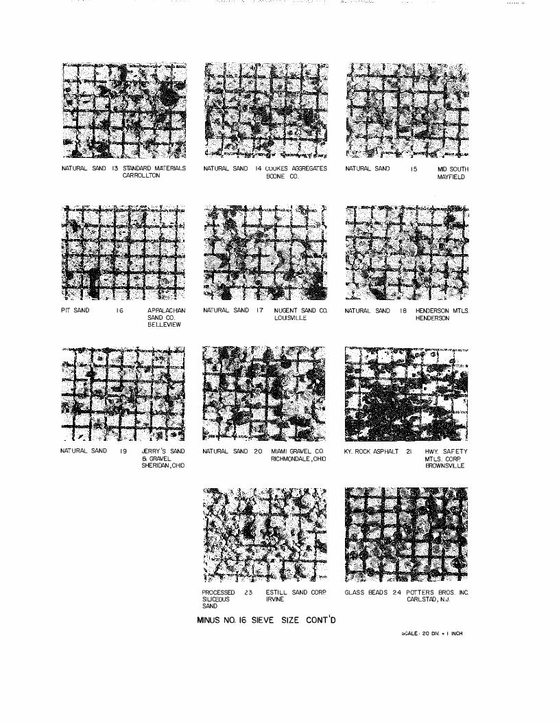
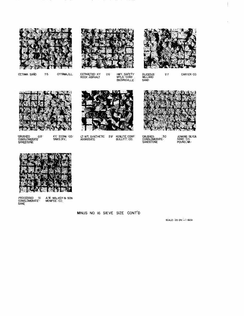
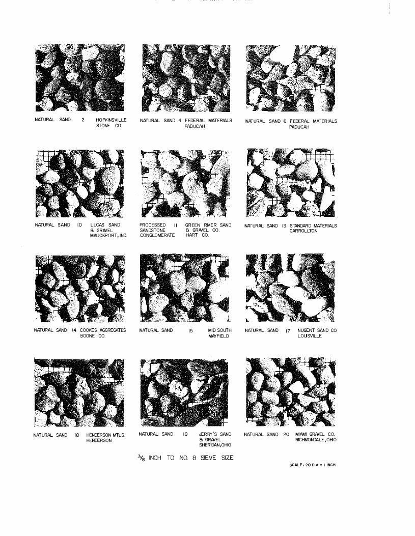
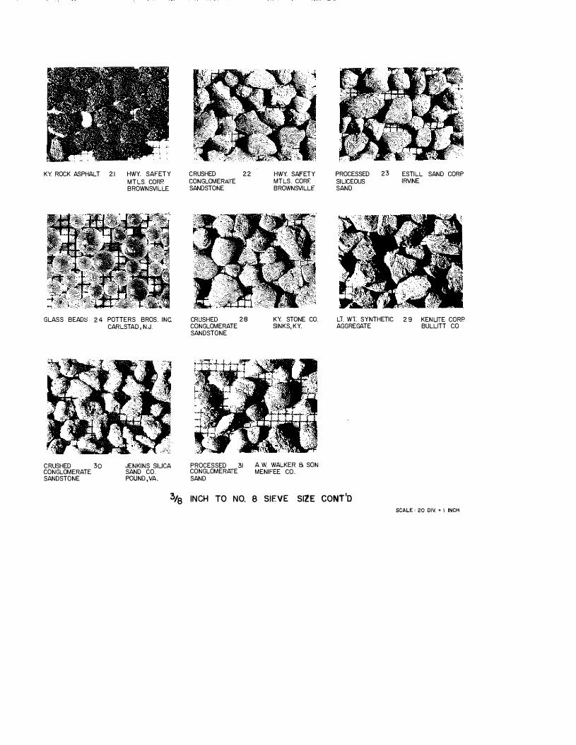
Magnified photographs were taken of approximately 30 native Kentucky sands, many of which have been used in bituminous concrete and sand-asphalt surfaces on state highways during the past
few years. Rounded and non-angular particles were found in surprising proportions -- particularity in the coarse fractions of many of the sands. In general, the river and terrace sands have unfavorable shapes. Sands produced from crushing conglomeritic sandstones, Kentucky rock asphalt, and lightweight synthetic (expanded shale) aggregate were found to offer high levels of sharpness and angularity. Photographs and descriptions of the sands are contained in APPENDIX B.
The sands were visually arrayed according to shape, i.e., grading from angular to round. The sands were grouped into four categories -- angular, subangular, subround, and round. Representative sands were chosen from each category, and dry-bulking tests were conducted in accordance with the procedure outlined in Special Provision No. 66-B (8)*. Six samples were washed and dried thoroughly and separated into the following four sizes:
Four repeat determinations were made on each size of each sand. The average constituted a test value. A percent voids was calculated for each size as outlined in the test procedure (8 ). Average percent voids for the four sizes were also calculated for each sand.
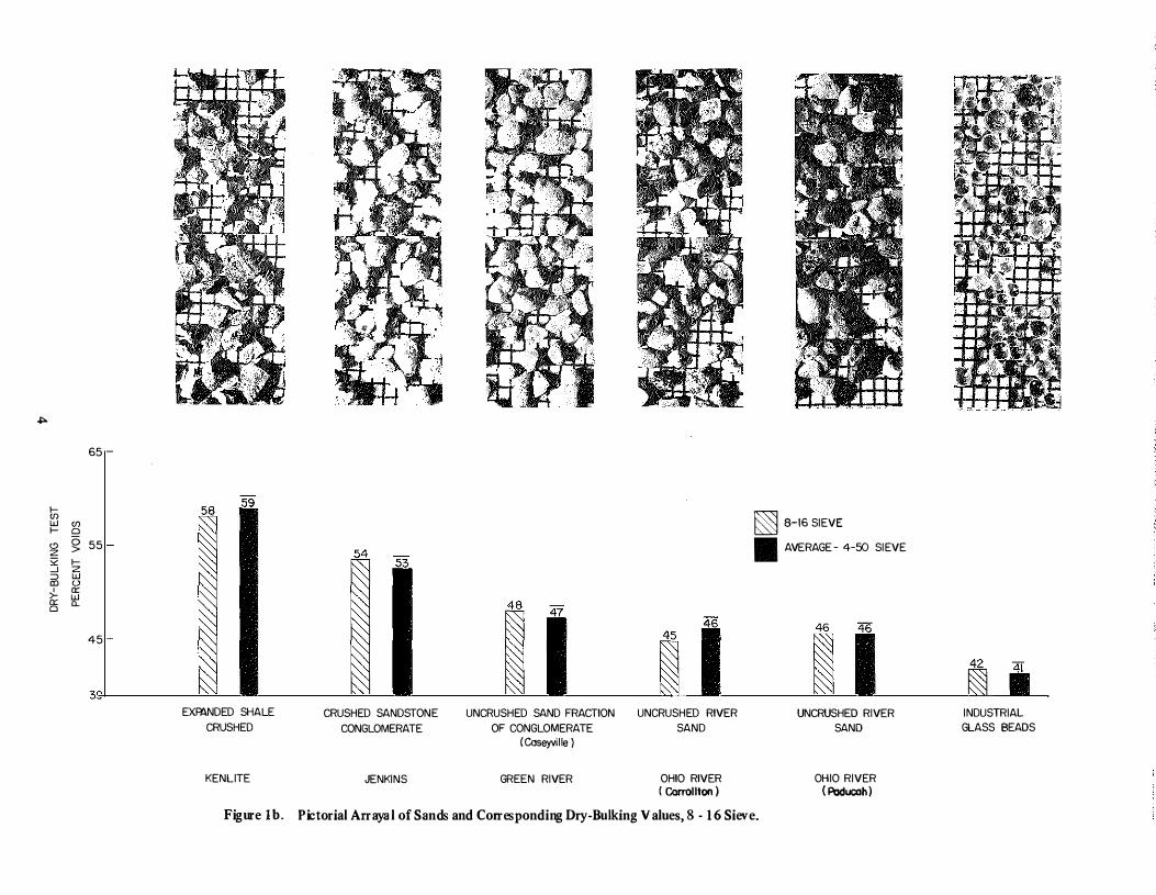
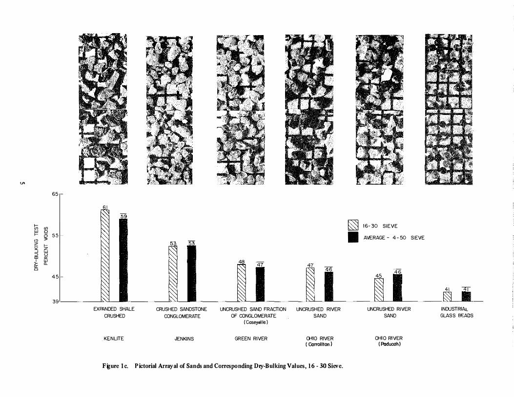
Percent voids for each sand size, along with average percent voids for each sand, in order of increasing roundness, were plotted. These pictorial arrayals of the sands were superimposed on the percent voids plots as shown in Figures la - ld. As the relative roundness -
based on visual analysis -- increases (left-to-right), the percent voids as calculated from the dry-bulking test decreases. Conversely, increasing voids are accompanied by noticeable increases in the angularity and sharpness of sand particles. Based on past skid-resistance performances of selected sands and judging the shape of the aggregates from the photographs, it was concluded that 50 percent voids or greater would be required to insure that a given aggregate would be sufficiently angular to perform satisfactorily from a skid resistance standpoint.
*Manufactured (Crushed) Limestone Fine Aggregate for Portland Cement Concrete. There, roundness is a preferred attribute.
2
Attached, as APPENDIX C, is a proposed specification for a skid-resistant sand-asphalt surface. It is recommended that the proposed specification replace Special Provision No. 22-A (Sand Asphalt Surface). In summary, the changes in Special Provision No. 22-A are as follows:
I. PAC-3 has been designated as the asphalt cement grade. This will increase the stability of the mix.
2. The minimum quartz content of the sand has been increased from 50 percent to 90 percent by visual count or 94 percent by chemical analysis. This will exclude soft aggregates.
3. The maximum amount of mineral filler in the aggregate combination has been decreased from 5 percent to 4 percent, and it shall only be used when required to meet the composition limits passing the No. 200 sieve. The composition limits have been changed as will be noted below.
4. The sand-equivalent and deleterious substances requirements have been deleted. With the high quartz requirement, these are not needed.
5. A particle shape requirement has been added, this being a minimum of 50 percent voids in the aggregate as determined by the dry-bulking test. This was necessitated by the fact that the rounded and subrounded sands are not providing the necessary traction. Only sharp, angular sands will meet this requirement.
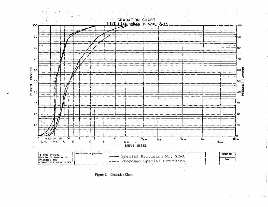
6. The aggregate gradation limits have been changed. More No. 8 and No. 16 and less No. 200 material will be admitted as indicated below and in Figure 2:
This coarser gradation on the No. 8 and 16 sieves will produce a mix with more voids. Requiring two percent or more passing the No. 200 sieve will increase stability.
7. The percent bitumen range has been widened from 7-10 to 6-10. The coarser gradation may require less asphalt.
Attached, as APPENDIX D, is a proposed specification for a skid-resistant Class I, Type A, Modified, bituminous surface containing lightweight aggregate. Several hundred lane miles of bituminous mixtures similar to that described in this specification have been placed in Texas and other states during recent years. Performance records indicate that they possess excellent non-skid properties for the life of the surface together with outstanding resistance against stability failures.
Lightweight aggregates, as stipulated in this specification, are typified by ASTM C 330. The cellular structure imparts a microMtexture to the aggregate surface.
The normal quidelines and design criteria for determining the optimum combination and gradation of aggregates and optimum percentages of asphalt are based on the unit weights (weight per unit volume) of typical or natural aggregates. These established weight-volume relationships are distorted somewhat when lightweight aggregates are substituted for a portion of the natural aggregates. When aggregates with widely different specific gravities are combined, the conventional gradation analysis based on weight measurements of the various size fractions cannot be used. A volumetric analysis must be used in order to obtain a realistic analysis of the gradation of the aggregate blend. In addition, the asphalt percentage should be controlled based on volumetric analysis. Procedures for ordinary field control are contained in the specification. The procedure proposed is basically similar to practices successfully employed in some districts in Texas.
DISCUSSION
Although high levels of aggregate angularity and sharpness have long been recognized as positive attributes to pavement skid resistance, quantitative measurements of these attributes from this standpoint have been largely nonexistent. Aggregate hardness has long been deemed an important consideration when predicting subsequent polish resistivity of aggregate types under traffic; however, this factor alone falls to assess the ultimate friction level of pavement surfaces.
8
Introduced herein is a test method for quantitatively assessing aggregate shape applicable to the skid resistance field. Pictorial arrayals of sands along with their respective shape values, as determined from the dry-bulking procedure, have been presented. It has been recommended that 50-percent voids as determined by the dry-bulking test be taken as the lower limit. This requirement would in essence rule out all uncrushed river, terrace, and pit sands. These materials have normally not proven to be skid resistant.
Materials meeting the requirements of this specification would be hard, angular, siliceous materials.
Specifications for skid-resistant, sand-asphalt surfaces and skid-resistant Class I, Type A, Modified, bituminous surfaces containing lightweight aggregates have been proposed.
R EFERENCES
I. Havens, J. H. and Williams, E. G., A Stndy of the Propert ies and Performance of Kentucky (Natural Sandstone) Rock Asphalt, Kentucky Department of Highways, February 1956.
2. Williams, E. G., A Test R oad for Evaluation of Sandstone as an Aggregate in Plant-Mix Bitnminous Pavements, Kentucky Department of Highways, April 1952.
3. Florence, R. L., The Design of Thin, Silica Sand-Asphalt Wearing Surfaces for Highway s Bridge Decks, Kentucky Department of Highways, July 1959.
4. Florence, R. L., Bridge Resurfacings with Silica Sand-Asphalt Mixture, Kentucky Department of Highways, March 1961.
5. Florence, R. L., Construction and Interim Performance of S il ica Sand-Asphalt Surfacing, Kentucky Department of Highways, February 1965.
6. Florence, R. L. and Southgate, H. F., Experimental Sand-Asphalt Surface, Kentucky Department of Highways, October 1970.
7. Standard Specifications for Road and Bridge Construction, Edition of 1965, Kentucky Department of Highways.
8. Manufactured Limestone Sand, Special Provision No. 66-B, Kentucky Department of Highways, March 1971.
9. Concrete and Mineral Aggregates, Standards, Part 10, American Society for Testing and Materials, November 1970.
10. Highway Materials, Part I - Specifications, lOth Edition, American Association of State Highway Officials, 1971.
11. Method of Test for Flat and Elongated Particles
in Coarse Aggregate, Designation CRD·Cll9-48, ·52, -53, Handbook for Concrete and Cement, Waterways Expertment Station, 1949, 1952, 1953.
12. Laughlin, G. R., Limestone Fine Aggregate in Portland Cement Concrete, Kentucky Department of Highways, February 1960.
13. Goldbeck, A. T., Stone Sand for Use as Fine
Aggregate, Concrete, Vol 59, 1951. 14. Shergold, F. A., The Percentage Voids in
Compacted Gravel as a Measure of Its Angularity,
Magazine of Concrete Research, No. 13, August 1953.
!5. Malhotra, V. M., Correlation between Particle
Shape and Surface Texture of Fine Aggregates and
Their Water Requirement, Materials Research and Standards, Vol 4, No. 12, 1964.
16. Huang, E. Y., An Improved Particle Index Test for
the Evaluation of Geometric Characteristics of
Aggregates, Journal of Materials, Vol 2, No. I, American Society for Testing and Materials, March 1967.
17. Moyer, R. A., and Shupe, J. W., Roughness and
Skid Resistance Measurements of Pavements in
California, Bulletin No. 37, Highway Research Board, 1951.
18. Shupe, J. W., and Goetz, W. H., A Laboratory
Investigation of Pavement Slipperiness, Bulletin No. 219, Highway Research Board, 1959.
19. Sabey, B. E., The Role of Temperature in Determining Seasonal Changes in Skid-Resistance Measured with t he Portable Tester, RN/3931, Road Research Laboratory, 1961.
20. White, A. M., and Thompson, H. 0., Tests for
Coefficients of Friction by the Skidding Car
Method on Wet and Dry Surfaces, Bulletin No. 186, Highway Research Board, 1958.
21. Mather, B., S hape, S urface Texture, and Coatings, STP No. 169, American Society for Testing and Materials, 1955.
22. Wadell, H., Volume, Shape, and Roundness of
Quartz Particles, Journal of Geology, Vol 43, 1935. 23. Krumbein, W. C., Measurement and Geological
24. Krumbein, W. C., and Sloss, L. L., St ratigraphy and Sedimentation, W. H. Freeman & Co., San Francisco, California, 1951.
9
25. Pettijohn, F. J., Sedimentary Rocks, Harper & Brothers, New York, N. Y., 1949.
26. Wentworth, C. K., A Method of Measuring and
Plotting the Shapes of Pebbles, Bulletin N o. 730, U. S. Geological Survey, 1922, Professional Paper No. 131, U. S. Geological Survey, 1923.
27. Wentworth, C. K., The Shapes of Rock Particles:
A Discussion, Journal of Geology, Vol 41, No. 3, April-May !933.
28. Wadell, H., Volume, Shape, and Roundness of
Rock Particles, Journal of Geology, Vol 40, 1932. 29. Wadell, H., Sphericity and Roundness of Rock
Particles, Journal of Geology,Vol 41, 1933. 30. Loudon, A. G., Geotechnique, Vol 3, No. 4,
December 1953. 31. Gray, J. E., and Bell, J. E., Stone Sand, Engineering
Bulletin 13, National Crushed Stone Association, 1964.
32. Rex, H. M., and Peck, R. A., A Laboratory Test
to Evaluate the Shape and Surface Texture of Fine
Aggregate Particles, Public Roads, Vol 29, No. 5, December 1956.
33. Huang, E. Y., A Test for Evaluating the Geometric
Characteristics of Coarse Aggregate Particles,
Proceedings, Vol 62, American Society for Testing and Materials, 1962.
34. Gray, J. E., Discussion of a paper by John G. Dempsey on The Effects of Fine Aggregate
Characteristics other than Grading on Strength and
Durability of Portland Cement Mortar, Proceedings, Vol 58, American Society for Testing and Materials, 1958.
35. Havens, J. H .. Discussion of Manufactured Stone Sand, Kentucky Department of Highways, April 1959.
APPENDIX A
Special Provision No. 22-A for
Sand Asphalt S nrface March 7, 1967
COMMONWEALTH OF KENTUCKY DEPARTMENT OF HIGHWAYS
SPECIAL PROVISION NO. 22-A
FOR
SAND ASPHALT S URFACE
This Special Provision covers the material requirements and construction methods for Hot-Mixed, Hot-Laid, Sand-Asphalt, Surface Course and shall be applicable to individual projecrs only when indicated on plans, proposals, or bidding invitations; and, when so indicated, it shall supersede all conflicting provisions of the Department's current Standard Specifications for Road and Bridge Construction. References herein are to the Department's Standard Specifications and approved addenda thereto.
I. DESCRIPTION
Hot-Mixed, Hot-Laid, Sand-Asphalt is intended to provide a fine-tex(ured, skid-resistant, wearing surface for pavements and bases. At least SO per cent of the sand therein shall consist of quartz (Si02). A proportion of the sand may consist of crushed limestone or slag sand. The sand, bituminous material, and the mixing and application thereof shall be in accordance with the respective requirements hereinafter described. The mixture shall be applied to the nominal, compacted thickness indicated on the plans or in the proposal; and the finished surface shall conform with the lines and grades shown on the plans or proposals.
II . . MATERIALS
A. Requirements.
I. Bituminous Materials. The asphalt cement to be mixed with the sand shall be of the grade specified on plans or proposals and shall meet the particular requirements of Section 621. The quantity of asphalt cement used shall be as directed by the Engineer.
Bituminous material for the tack coat shall meet the requirements of Section 621 for the particular type and grade specified on the plans or proposals.
2. Aggregate. The aggregate shall consist, by weight, of not less than SO per cent quartz (Si02). Quartz, to fulfill this requirement, shall be obtained from crushed sandstone, conglomeratic sand, bank sand, river sand or combinations thereof. The remaining portion of aggregate shall consist of quartz sand, limestone sand, slag sand, or blends thereof. Unless otherwise provided, mineral filler meeting the requirements of Article 6ll.S.O for quality may comprise not more than S per cent of the aggregate combination. Each aggregate, except mineral filler, shall have a minimum Sand-Equivalent value of l 0 as determined by AASHO T 176, and the total combined aggregate, including mineral filler, shall have a minimum Sand-Equivalent value of 3S. Deleterious substances retained on the No. 200 sieve shall not exceed the following percentages by weight of the total combined aggregate.
Clay lumps Other deleterious substances such as,
but not limited to, alkali, mica, shale, coated grains, soft and flaky particles
Per Cent by Weight
None
1.0
3. Admixture. A moisture controlling admixture such as silicone fluid ( dhnethyl siloxane polymer) shall be furnished by the Contractor to be blended with the mix when and as directed by the Engineer.
B. Approval of Materials. Silicone shall be of a type approved by the Department and shall be from a source approved by the Department.
At least one week prior to commencing production, the Contractor shall notify the Engineer that the aggregates, including blended natural sand if used, have been stocked at the job site. Prior to notification, at least 500 tons or one-half the anticipated project requirement, whichever is least, of each aggregate shall be stocked.
III. C ONSTRUCTION METHODS
The construction methods shall comply with the applicable requirements of Article 306.3.0, except as otherwise provided hereinafter and on the plans or in the proposals.
A. S easonal and Weather Limitations. No sand asphalt surface as defined by thls special provision shall be laid between September 30 and May I, nor when the temperature is below 60 degrees F., except by written permission of the Engineer, nor when the underlying course is wet, nor when other weather conditions are unsuitable.
B. Preparation of Mixture.
1. Composition of Mixture. The sand and asphalt cement shall be combined in such proportions that the composition of the mixture by weight shall be withln the general limits given in the following table. A job-mix formula, withln the specified composition limits, shall be established by the Engineer for each project; and the proportions and gradings so set shall be maintained withln the tolerances specified hereinafter. The percentages passing all sieve sizes shall be determined by dry sieving. These permissible tolerances from the job-mix formula shall not permit the use of any mixture which will be outside the specified composition lhnits. Once the job-mix formula has been established, it shall remain in effect until changed in writing by the Engineer. Deviations from the job-mix formula shall not exceed 0.5 percentage points in the asphalt content and 0.2 in fineness modulus of the sand gradation.
Sieve
1/4 inch No. 8 No. 16 No. 30 No. 50 No. 100 No. 200 Per Cent Bitumen
Composition Limits
Per C ent Passing
100 88-100 70-95 50-90 20-65
5-20 1-8 7-10
2. Preparation of Aggregates. If sands from two or more sources are blended, they shall be metered from individual cold bins in such proportions that will yield a product having the specified gradation. The sand shall be uniformly dried and heated to a temperature of not less than 280°F nor more than 325°F. If mineral filler is used, it shall be weighed or metered into the mix from a separate bin.
3. Temperature Requirements. Unless otherwise approved by the Engineer, the temperatures of the materials and the mixtures, in degrees Fahrenheit, shall be maintained within the ranges given in the following table:
Mixing and Laying Temperatures
Aggregates Asphalt Cement Mixture at Plant Mixture When Laid
C. Spreading and Finishing.
Min. 280 - Max. 325 Min. 265 · Max. 325 Min. 280 - Max. 325 Min. 280 · Max. 310
1. Paver Speed. Unless otherwise directed by the Engineer, the paver when placing the surface mix shall maintain a speed of 22 feet per minute, plus or minus 8 feet per minute.
2. Continuous Paver Operation. The plant production and the paver speed shall be synchronized in such a manner which will permit the paver to travel in a uniform continuous forward speed within the limits as required hereinbefore. The paver shall engage the hauling trucks while traveling forward. Every effort shall be made to keep the paver moving continuously. The paver should be permitted to stop only when a plant or paver breaks down or when some emergency or unavoidable condition exists.
3. Entrances and Crossovers. Entrances, crossovers, and other areas inaccessible to the paver which must be spread by hand, whether constructed of sand asphalt or other surface mixture, shall be constructed as a separate operation. The material for these areas shall be placed directly from the trucks. The paver shall not be stopped, side plates removed, and the material for these areas allowed to spill out to the side, or the paver shall not be stopped and material for these areas shoveled from the hopper.
4. Pavement Samples. Samples shall not be cut from the pavement unless directed by the Engineer.
5. Compaction. Unless otherwise directed or permitted by the Engineer, compaction, including breakdown rolling, shall be accomplished with a 3-wheel roller or a tandem roller weighing not Jess than 8 tons. Entrances, crossovers and other inaccessible areas spread by hand shall be compacted with roller weighing not less than 3 tons.
6. Leveling and Patching. Leveling and patching shall be performed in a manner, with the designated equipment and with the materials, as prescribed on the plans or in the proposal.
IV. METHOD OF MEASUREMENT
The sand asphalt will be weighed in accordance with Article 1.9 .1 Bituminous material, except that used in the sand-asphalt mixture, will be measured in gallons as specified in Section 621.
V. BASIS OF PAYMENT
The quantities thus measured and accepted, complete and in place, will be paid for at the contract unit price bid per gallon for "Bituminous Materials," per ton for 11Sand-Asphalt Mixture;11 which payment shall be full compensation for cleaning surface, for furnishing, hauling, and placing all materials, including
the silicone fluid, and for all labor, equipment, ,tools, and incidentals necessary to complete the work.
APPROVED March 7, 1967
A. 0. NEISER STATE IDGHWAY ENGINEER
APPENDIX B
I. Photomicrographs of Size-Fractions of Various Sands
2. Identification, Source, and Uses of Various Sands
BLOW SAND V\NCENNES,!ND.
NATURAL SAND 4 FEDERAL MATERIALS PA DUCAH
MORTAR SAND 7 STANDARD MATERIALS CARROLLTON
NATURAL SAND 10 LUCAS SAND S GRAVEL MAUCKPORT, IND.
NATURAL SAND
PIT SAND
KY. RIVER SAND
PRO CESSED I I SANDSTONE CONGLOMERATE
5
2
8
HOPKINSVILLE STONE co
REED PIT G ILBERTSVILLE
FRANKFORT
GREEN RIVER SAND S GRAVEL CO. HART CO.
MINUS NO. 16 SIEVE SIZE
PIT SAND 3 DeBURK PIT LEADBETTER,KY.
NATURAL SAND 6 FEDERAL MATERIALS PA DUCAH
01T SAND 9
PIT SAND 12
MILL�RS L ANE PIT LOUISVILLE SAND 9! GRAVEL
RaW PIT LOU ISVILLE
SCALE' 20 DIV. � I INCH
NATURAL SAND 13 STANDARD MATERIALS CARROLLTON
P IT SAND 16
NATURAL SAND 19
APPALACHIAN SAND CO. BELLEVIEW
JERRY's SAND a GRAVEL SHERIDAN ,OHIO
NATURAL SAND 14 GUUKES AGGREG ATES BOONE CO.
NATURAL SAND 17 NUGENT SAND CO. LOUISVILLE
NATURAL SAND 20 MIAMI GRAVEL CO.
PROCESSED 2 3 SILICEOUS SAND
RICHMONDALE ,OHIO
ESTILL SAND CORP. IRVINE
MINUS NO. 16 SIEVE SIZE CONT'D
NATURAL SAND 15 MID SOUTH MAYFIELD
NATURAL SAND IS HENDERSON MTLS.
KY. ROCK ASPHALT 21
HENDERSON
HWY. SAFETY MTLS. CORP. BROWNSVILLE
GLASS BEADS 24 POTTERS BROS. INC. CARLSTAD, N.J.
;:,GALE' 20 DIV. = I INCH
OTTAWA SAND ?5 O TTMA,ILL.
KY. STON�- co.· SINKS,KY.
PROCESSED 31 A W. WALKI';R a SON CONGLOMERAT£ MENIFEE CO; SANC
LT. WT. SYNTHETIC 2 9 KENLITE CORP. AGGREGATE BULLITT CO
3;8 INCH TO NO. 8 SIEVE SIZE CONT'D SCALE' 20 DIV. = l INCH
SAJID li!UMBER
1
2
3
4
5
6
7
8
9
10
11
12
13
14
15
DESCRIPTION-,
Blow Sand
Natural Sand
Pit sand
Natural Sand
Pit Sand
Natural River Sand
Mortar Sand
Ky. River Sand
Pit Sand
Natural Sand
Processed Sandstone Conglomerate
Pit Sand
Natural Sand
Natural-Sand
Natural Sand
SOURCE
Vincennes, Ind.
Hopkinsville Stone Co.
DeBurk Pit Leadbetter·, Ky.
Federal Materials Paducah
Reed Pit GilbertsVille
Federal Materials Paducah
Standard Materials Carrollton
Kentucky River (StoCkpile-at Carter's Plant)
Millers Lane Pit Louisville Sand & Gravel
Lucas Sand & Gravel Mauckport, -l:nd.
Green River Sand & Gravel Co. Jonesville, Ky. (Hart Co.)
R&W Pit Louisville
Standard Materials Carrollton
Cookes Aggregates Petersburg, Ky. (Boone Co.)
Fred Riley {Mid South} Mayfield, Ky.
USE
Sand-Asphalt Surface Madisonville-Hanson us 41
Sand-Asphalt Surface us 62
Sand-Asphalt Surface Ky 121 West of Murry
Sand-Asphalt Surface
Sand-Asphalt Surface
Sand-Asphalt Surface
Experimental SandAsphalt north of SOmerset US 27
Sand-Asphalt Surface Irvington - Ky 144 us 60 Sand-Asphalt Surface Lawrenceburg-Tyrone us 62 Sand-Asphalt Surface Cinn. Airport Rd. Ky 236
PROJECT
Hopkins SP 54-20
McCracken Sp 73-72-12
Calloway SP 18-123-5
SP 64-8 Bob Carter, Frankfort
Franklin SP 37-55
SP 64-8 Bob carter, Frankfort
Pulaski SP-100-535
Breckinridge-Meade SP 14-333-3, SP 82-423-3
Anderson SP 612-8
Boone-Kenton SP 8-270-5, SP 59-3215-4
DATE SAMPLED
Sept, 1966
' july, 1966
June, 1967
Aug, 1966
May, 1967
Aug, 1966
Aug, 1968
Oct, 1966
July, 1966
J:une, 1966
1970
APPENDIX C
Proposed Specification for Sand-Asphalt Snrface (Skid Resistant)
COMMONWEALTH OF KENTUCKY DEPARTMENT OF HIGHWAYS
SPECIAL PROVISION NO.
FOR
SAND·ASPHALT SURFACE (SKID RESISTANT)
This Special Provision covers the material requirements and construction methods for Hot·Mixed, Hot·Laid, Sand· Asphalt, Surface Course and shall be applicable to individual projects only when indicated on plans, proposals, or bidding invitations; and, when so indicated, it shall supersede all conflicting provisions of the Department's current S tandard Specifications for Road and Bridge Construction. References herein are to the Department's Standard Specifications and approved addenda thereto.
I. DESCRIPTION
Hot.Mixed, Hot·Laid, Sand·Asphalt is intended to provide a fine·textured, skid·resistant wearing surface for pavements and bases. The sand, bituminous material, and the mixing and application thereof shall be in accordance with the respective requirements hereinafter described. The mixture shall be applied to the nominal, compacted thickness indicated on the plans or in the proposal; and the fmished surface shall conform with the lines and grades shown on the plans or proposals.
II. MATERIALS
A. Requirements.
1. Bituminous Materials. The asphalt cement to be mixed with the sand shall be P AC·3 unless otherwise specified on plans or proposals and shall meet the particular requirements of Section 621. The quantity of asphalt cement used shall be as directed by the Engineer.
Bituminous material for the tack coat shall meet the requirements of Section 621 for the particular type and grade specified on the plans or proposals.
2. Aggregate. The aggregate shall consist of quartz (Si02) not less than 90 percent by visual count or 94 percent by chemical analysis. Quartz, to fulfill this requirement, shall be obtained from sandstone, conglomeratic sand, bank sand, river sand, or combinations ther.e·of. Unless otherwise provided, mineral filler meeting the requirements of Article 611.5.0 for quality may comprise not more than 4 percent of the aggregate combination. Mineral filler shall be added only when necessary to meet with the composition limits passing the No. 200 sieve. Pre-qualification of the aggregate source is required. Pre·qualification, here, means prior approval of the Engineer.
Particle shape and texture of each sand shall be so controlled that, when subjected to the dry·bulking test, the volume of voids shall be 50 percent or greater. The dry·bulking test shall be used as a source control test and thereafter shall be conducted as often as deemed necessary by the Engineer. The specified procedure follows:
I. Balance .. a balance having a capacity of 1500 grams and a sensitivity of 0.1 gram.
2. Drying Pans .. at least lSOO·gram capacity, suitable for drying samples.
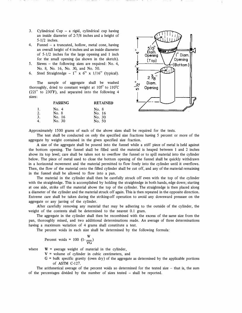
3. Cylindrical Cup .. a rigid, cylindrical cup having an inside diameter of 2-7/8 inches and a height of 5-1/2 inches.
4. Funnel ·· a truncated, hollow, metal cone, having an overall height of 4 inches and an inside diameter of 5-1/2 inches for the large opening and I inch for the small opening (as shown in the sketch).
5. Sieves ·· the following sizes are required: No. 4, No. 8, No. 16, No. 30, and No, 50.
6. Steel Straightedge .. !" x 6" x 1/16" (typical).
The sample of aggregate shall be washed thoroughly, dried to constant weight at 105° to IIOoC (22lo to 230oF), and separated into the following 4 sizes:
PASSING RETAINED
I. No.4 No. 8 2. No. 8 No. 16 3. No. 16 No. 30
4. No. 30 No. 50
=
=
i 2 'Ya" Diem.
Opening
_l
Approximately 1500 grams of each of the above sizes shall be required for the tests. The test shall be conducted on only the specified size fractions having 5 percent or more of the
aggregate by weight contained in the given specified size fraction. A size of the aggregate shall be poured into the funnel while a stiff piece of metal is held against
the bottom opening. The funnel shall be filled until the material is heaped between I and 2 inches above its top level; care shall be taken not to overflow the funnel or to spill material into the cylinder below. The piece of metal used to close the bottom opening of the funnel shall be quickly withdrawn in a horizontal movement and the material permitted to flow freely into the cylinder until it overflows. Then, the flow of the material onto the filled cylinder shall be cut off, and any of the material remaining in the funnel shall be allowed to flow into a pan.
The material in the cylinder shall then be carefully struck off even with the top of the cylinder with the straightedge. This is accomplished by holding the straightedge in both hands, edge down; starting at one side, strike off the material above the top of the cylinder. The straightedge is then placed along a diameter of the cylinder and the material struck off again. This is then repeated in the opposite direction. Extreme care shall be taken during the striking-off operation to avoid any downward pressure on the aggregate or any jarring of the cylinder.
After carefully removing any material that may be adhering to the outside of the cylinder, the weight of the contents shall be determined to the nearest 0.1 gram.
The aggregate in the cylinder shall then be recombined with the excess of the same size from the pan, thoroughly mixed, and two additional determinations made. An average of three determinations having a maximum variation of 4 grams shall constitute a test.
The percent voids in each size shall be determined by the following formula:
where
w Percent voids = 100 (I·-)
VG
W = average weight of material in the cylinder, V = volume of cylinder in cubic centimeters, and G = bulk specific gravity (oven dry) of the aggregate as determined by the applicable portions
of ASTM C-127. The aritinnetical average of the percent voids so determined for the tested size .. that is, the sum
of the percentages divided by the number of sizes tested .. shall be reported.
3. Admixture. A moisture-controlling admixture such as silicone oil (dimethyl siloxane polymer) shall be furnished by the Contractor to be blended with the mix when and as directed by the Engineer.
B. Approval of Materials. Silicone shall be of a type and from a source approved by the Department. At least one week prior to commencing production, the Contractor shall notify the Engineer
that the aggregates, including blended natural sand if used, have been stocked at the plant site. Prior to notification, at least 500 tons or one-half the anticipated project requirement, whichever is least, of each aggregate shall be stocked.
III. CONSTRUCTION METHODS
The construction methods shall comply with the applicable requirements of Article 306.3.0, except as otherwise provided hereinafter and on the plans or in the proposals.
A. S easonal and Weather Limitations. No sand-asphalt surface as defined by this special provision shall be laid between November 1 5 and May I, nor when the temperature is below 60°F, except by written permission of the Engineer, nor when the underlying course is wet, nor when other weather conditions are unsuitable.
B. Preparation of Mixture.
1. Cqmposition. The sand and asphalt cement shall be combined in such proportions that the composition of the mixture by weight shall be within the general limits given in the following table. A job-mix formula, within the specified composition limits, shall be established by the Engineer for each project; and the proportions and gradings so set shall be maintained within the tolerances specified hereinafter. The percentages passing all sieve sizes shall be determined by dry sieving. Once the job-mix formula has been established, it shall remain in effect until changed in writing by the Engineer. Deviations from the j ob-mix formula shall not exceed 0.5 percentage points in the asphalt content and 0.2 in fineness modulus of the sand gradation.
2. · Preparation of Aggregates. If sands from two or more sources are blended, they shall be metered from individual cold bins in such proportions that will yield a product having the specified gradation. The sand shall be uniformly dried and heated to a temperature of not less than 280op nor more than 325op. If mineral filler is used, it shall be weighed or metered into the mix from a separate bin.
3. Temperature Requirements. Unless otherwise approved by the Engineer, the temperatures of the materials and the mixtures, in degrees Fahrenheit, shall be maintained within the ranges given in the following table:
Mixing and Laying Temperatures
Aggregates Asphalt Cement Mixture at Plant Mixture When Laid
C. Spreading and Finishing.
Min. 280 - Max. 325 Min. 265 - Max. 325 Min. 280 · Max. 325 Min. 280 - Max. 31 0
I. Paver Speed. Unless otherwise directed by the Engineer, the paver, when placing the surface mix, shall maintain a speed of 22 feet per minute, plus or minus 8 feet per minute.
2. Continuous Paver Operation. The plant production and the paver speed shall be synchronized in such a manner which will permit the paver to travel in a uniform continuous forward speed within the lhnits as required hereinbefore. The paver shall engage the hauling trucks while traveling forward. Every effort shall be made to keep the paver moving continuously. The paver should be permitted to stop only when a plant or paver breaks down or when some emergency or unavoidable condition exists.
3. Entrances and Crossovers. Entrances, crossovers, and other areas inaccessible to the paver which must be spread by hand, whether constructed of sand asphalt or another surface mixture, shall be constructed as a separate operation. The material for these areas shall be placed directly from the turcks. The paver shall not be stopped, side plates removed, and the material for these areas allowed to spill out to the side, or the paver shall not be stopped and material for these areas shoveled from the hopper.
4. Pavement Samples. Samples shall not be cut from the pavement unless directed by the Engineer.
5. Compaction. Unless otherwise directed or permitted by the Engineer, compaction, including breakdown rolling, shall be accomplished with a 3-wheel roller or a tandem roller weighing not less than 8 tons. Entrances, crossovers and other inaccessible areas spread by hand shall be compacted with a roller weighing not less than 3 tons.
6. Leveling and Patching. Leveling and patching shall be performed in a manner, with the designated equipment, and with the materials as prescribed on the plans or in the proposal.
IV. METHOD OF MEASUREMENT
The sand asphalt will be weighed in accordance with Article 1.9.1. Bituminous material, except that used in the sand-asphalt mixture, will be measured in gallons as specified in Section 621.
V. BASIS OF PAYMENT
The quantities thus measured and accepted, complete and in place, will be paid for at the contract unit price bid per gallon for "Bituminous Materials11 and per ton for 11Sand-Asphalt Mixture," which payment shall be full compensation for cleaning surface; for furnishing, hauling, and placing all materials, including the silicone fluid; and for all labor, equipment, tools, and incidentals necessary to complete the work.
APPROVED
STATE IDGHWAY ENGINEER
APPENDIX D
Proposed Special Provision for
C lass I, Type A, Modified Snrface (Skid-Resistant, Lightweight Aggregate)
COMMONWEALTH OF KENTUCKY DEPARTMENT OF HIGHWAYS
SPECIAL PROVISION NO.
FOR
CLASS I, TYPE A, MODIFIED SURFACE (SKID-RESISTANT, LIGHTWEIGHT AGGREGATE)
This Special Provision covers the material requirements and construction methods for Hot-Mixed, Hot-Laid, Skid-Resistant, Class I, Type A Modified Bituminous Concrete Surface Course and shall be applicable to individual projects only when indicated on plans, proposals, or bidding invitations; and, when so indicated, it shall supersede all conflicting provisions of the Department's current Standard Specifications for Road and Bridge Construction. References herein are to the Department's Standard Specifications and approved addenda thereto.
I. DESCRIPTION
Hot-Mixed, Hot-Laid, Skid-Resistant, Class I, Type A, Modified Bituminous Concrete is intended to provide a skid-resistant wearing surface for pavements and bases. At least 40 percent by volume of the aggregate therein shall consist of lightweight aggregate prepared by expanding clay, shale, or slate by the rotary kiln process. The remaining portion of the aggregate shall meet the applicable requirements of Special Provision No. (Skid-Resistant Sand-Asphalt Surface). The aggregate, sand, bituminous material and the mixing and application thereof shall be in accordance with the respective requirements hereinafter described.' The mixture shall be applied to the nominal, compacted thickness indicated on the plans or in the proposal; and the finished surface shall conform with the lines and grades shown on the plans or proposals.
II. MATERIALS
A. Requirements.
I. Bituminous Materials. The asphalt cement to be mixed with the aggregate shall be PAC-5 (AC-10) 85-100 penetration unless otherwise specified on plans or proposals and shall meet the particular requirements of Section 621. The quantity of asphalt cement used shall be as directed by the Engineer.
Bituminous material for the tack coat shall meet the requirements of Section 621 for the partiuclar type and grade specified on the plans or proposals.
2. Aggregate. The aggregate shall consist, by volume, of not less than 40 percent of lightweight aggregate. Aggregate, to fulfill this requirement, shall be obtained by expanding clay, shale, or slate at an elevated temperature in a rotary kiin. The remaining portion of the aggregate shall meet the applicable requirements Special Provision No. . Unless otherwise provided, mineral filler meeting the requirements of Article 611.5.0 for quality may comprise not more than 5 percent by weight of the aggregate combination. Pre-qualifications of the aggregate sources are required. Pre-qualification, here, means prior approval of the Engineer.
The lightweight aggregate shall conform to the grading requirements for No. 8 coarse aggregate as follow :
Sieve
1/2 inch 3/8 inch No. 4 No. 8 No. 16
Percent Passing
100 85-100 10-30 0-10 0-5
In addition, the lightweight aggregate shall possess the following properties:
Loose unit weight - 35 pcf minhnum (ASTM Designation C 29 (shoveling procedure)) Los Angeles Abrasion, percent loss -- 35 minhnum (ASTM Designation C 1 3 1 )
The remaining portion o f the aggregate, including mineral filler, shall conform to the following grading requirements:
In addition, the remaining portion of the aggregate shall consist of quartz (Si02), not less than 90 percent by visual count or 94 percent by chemical analysis. Quartz, to fulfill this requirement, shall be obtained from sandstone, conglomeratic sand, bank sand, river sand, or combinations thereof.
Particle shape and texture of each aggregate type, excluding mineral filler, shall be so controlled that when subjected to the dry-bulking test, the volume of voids shall be 50 percent or greater. The dry-bulking test shall be used as a source control test and will be conducted at frequencies deemed necessary by the Engineer. The dry-bulking test shall be conducted in accordance with the procedure specified in Special Provision No.
3. Admixture. A moisture-controlling admixture such as silicone fluid (dimethyl siloxane polymer) shall be furnished by the Contractor to be blended with the mix when and as directed by the Engineer.
B. Approval of Materials. Silicone shall be of a type and from a source approved by the Department. At least one week prior to commencing production, the Contractor shall notify the Engineer
that the aggregates, including blended natural sand if used, have been stocked at the plant site. Prior to notification, at least 500 tons or one-half the anticipated project requirement, whichever is least, of each aggregate shall be stocked.
III. CONS TRUCTI ON METHODS
The construction methods shall comply with the applicable requirements of Article 306.3.0, except as otherwise provided hereinafter and on the plans or in the proposals.
A. Seasonal and Weather Limitations. No surface as defined by this special provision shall be laid between November 15 and May 1, nor when the temperature is below 60°F, except by written permission of the Engineer, nor when the underlying course is wet, nor when other weather conditions are unsuitable.
B. Preparation of Mixture.
1. Composition of Mixture. The aggregate and asphalt cement shall be combined in such proportions that the composition of the mixture by volume shall be within the general limits for Class I, Type A Modified Surface given in the following table. A job-mix formula, within the specified composition limits, shall be established by the Engineer for each project; and the proportions and gradings so set shall be maintained within the tolerances specified hereinafter. The percentages passing all sieve sizes shall be determined by dry sieving. Once the job-mix formula has been established, it shall remain in effect until changed in writing by the Engineer. Deviations from the job-mix formula shall not exceed 0.5 percentage points in the asphalt content and 0.2 in fineness modulus of the sand gradation.
2. Field Control of Mixture. The relative percentages of the different aggregates in the mixture shall be controlled at the cold feeds. The "procedure for calibration and checking of cold feed flow on a bituminous hot-mix plant" as outlined in the Bituminous Manual shall be used.
Aggregate samples for gradation analyses shall be taken from the hot bins. The procedure for "sampling of hot aggregate bins" as outlined in the Bituminous Manual shall be used. Samples from the bins shall be combined on a weight basis according to the particular design bin percentages. A volumetric sieve analysis of the combined aggregate shall then be performed according to the following procedure:
S cope:
TEST METHOD
VOLUMETRIC SIEVE ANALYSIS OF FINE AND COARSE AGGREGATES
This test method covers a procedure for the determination of the particle size distribution by volume of fine and coarse aggregate samples, using sieves with square openings. The method is also applicable for the sieve analysis of aggregate recovered from bituminous mixtures obtained from plant or roadway.
Apparatus: 1. Sample splitter, quartering cloth, shoveling method on clean surface, or quartering machine. 2. Set of Standard U.S. Sieves -- woven wire with square openings (ASTM Designation: E-ll). 3. Mechanical Sieve Shaker. 4. Drying oven capable of attaining a temperature of 200oF or more. 5. Graduate -- a plastic cylinder with a capacity of 4,000 ml graduated in increments of 50 ml
or less.
6. A wide·mouth funnel for transferring aggregates to graduate. 7. Solvent ·· Benzol, trichloroethane. 8. Round pans with diameter to fit sieves. 9. Scoop, brass wire brush, and hair brush.
Preparation of Sample: 1. Select a representative portion of processed aggregate for test. 2. Place the aggregate in oven and dry to constant weight at a temperature of 140o to 300°F.
Remove sample from oven and allow to cool to room temperature. 3. To quarter the material, use either the sample splitter, the quartering cloth, quartering machine,
or the method of manipulating the aggregate with a large flat scoop or shovel, blending it back and forth on a smooth clean surface until blended and then quartering mechanically with some straightedge, thus reducing the dry aggregate sample to laboratory testing size. It is permissible to thoroughly blend the fine material and to take small portions from several places covering the entire area of the pan to make up the test sample. Approximately 3000 ml of aggregate shall be used.
Procedure: 1. Place the set of sieves, with the largest opening on top, into a pan and pour the aggregate
onto the top sieve. Perform a sieve analysis on the aggregate sample by separating the material into a series of particle sizes using such sieves as are necessary to determine compliance with the specifications for the material. The hand sieve operation is done by means of a lateral ' and vertical motion of the sieves, accompanied by a jarring action so as to keep the material moving continuously over the surface of the sieves. In any case, do not turn or manipulate particles through the openings of the sieves by hand. Continue hand sieving until, by visual observation, no material continues to pass through the sieves in use. When mechanical sieving is used, shaking time should be established that will assure proper sieving of the material without degradation. Check the thoroughness of the sieving by the above described method.
2. Fill the graduate with solvent to a level to cover the entire sample of aggregate. Make an initial reading of the liquid level and record on work sheet. Place the aggregate retained on each sieve size and pan into the graduate, starting with the smallest size. After each size of aggregate is placed in the graduate, make a reading of the liquid level and record on the work sheet. For highly absorptive aggregates, each successive size of aggregates should be added at intervals of approximately 30 seconds and the liquid level reading taken approximately 1 5 seconds after each addition of aggregate. The same timing should be used on each test so that results will be comparable.
Care should be taken to eliminate entrapped air in the graduate, particularly after the fine aggregate is added. This can be done by gently rolling the graduate or stirring the aggregate prior to taking a reading of liquid level. After each test is completed, the solvent may be decanted or filtered and saved for reuse.
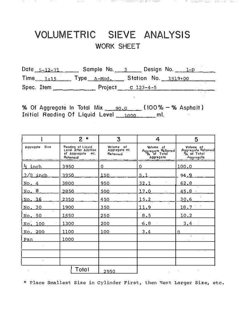
By subtracting the liquid reading prior to the addition of each size of aggregate from the liquid reading after the addition of aggregate, the volume of each size of aggregate may be determined. This information is to be entered in Column 3 of the work sheet. The difference in initial and final readings will be the total volume of the aggregate. Divide each volume of aggregate by total aggregate volume to determine percent retained on each sieve and enter in Column 4. This percent will be an expression of each size as a portion of the total aggregate. The cumulative percent passing each sieve is then calculated and entered in Column 5 . This gradation in Column 5 is to be compared with the volumetric composition limits for compliance with the specifications.
Asphalt content determination shall be made in accordance with the standard procedure. The asphalt content as determined by weight shall then be transformed to a volumetric percentage based on the volume of the total mixture. Sample calculations follows :
A. Asphalt Content (by weight) by extraction B. Specific Gravity of Asphalt
9.4% 1.026
VOLUMETR I C S IEVE ANALYS I S WORK SHEET
Date _..s.::.-.�o.l2"'-::..7!..!1�-- Sample No. 3 Desig n No. 1-n
Time -�1.._.· ..... 1""5__ Type A -Mod S tat ion No. _.=.1""5 1"'9"-'+'-!:o:.!<o ___ _
0/o Of Aggregate I n Total Mix 9o . o ( I O O <>t.:, - % Aspha lt ) Ini t i a l R ea d i n g O f Liqu id Level _ _.l ... o""oou._ __ ml .
I 2 * 3 4 5 Aggregate Si z e Reading of Liquid Volume of Volume of Volume of
Level After Addition Aggregate mi. A92t"e9cHe Retatn�Z.d A�9.-egqle R<1olo1n<d of Aggregate mi. Retam<�.d Yo of Total 7o Of Toto I Retatne.d Aggreg a te . Agsrego�
The volumetric asphalt content is to be compared with the volumetric composition limits for compliance with the specifications.
2. Preparation of Aggregates. If aggregates from two or more sources are blended, they shall be metered from individual cold bins in such proportions that will yield a product having the specified composition and gradation. The aggregates shall be uniformly dried and heated to a temperature of not less than 280oF nor more than 325oF. If mineral filler is used, it shall be weighed or metered into the mix from a separate bin.
3. Temperature Requirements. Unless otherwise approved by the Engineer, the temperatures of the materials and the mixtures, in degrees Fahrenheit, shall be maintained within the ranges given in the following table:
Mixing and Laying Temperatures
Aggregates Min. 280 Max. 325 Asphalt Cement Min. 265 Max. 325 Mixture at Plant Min. 280 Max. 325 Mixture When Laid Min. 280 - Max. 310
c. Spreading and Finishing.
1. Paver Speed. Unless otherwise directed by the Engineer, the paver when placing the surface mix shall maintain a speed of 22 feet per minute, plus or minus 8 feet per minute.
2. Continuous Paver Operation. The plant production and paver speed shall be synchronized in such a manner which will permit the paver to travel in a uniform continuous forward speed within the limits as required hereinbefore. The paver shall engage the hauling trucks while traveling forward. Every effort shall be made to keep the paver moving continuously. The paver should be permitted to stop only when a plant or paver breaks down or when some emergency or unavoidable conditions exists.
3. Entrances and Crossovers. Entrances, crossovers, and other areas inaccessible to the paver which must be spread by hand, whether constructed of this mixture or another surface mixture, shall be constructed as a separate operation. The material for these areas shall be placed directly from the trucks. The paver shall not be stopped, side plates removed, and the material for these areas allowed to spill out to the side, or the paver shall not be stopped and material for these areas shoveled from the hopper.
Engineer. 4. Pavement Samples. Samples shall not be cut from the pavement unless directed by the
5. Compaction. Unless otherwise directed or permitted by the Engineer, compaction, including breakdown rolling, shall be accomplished with a 3-wheel roller or a tandem roller weighing not less than 8 tons. Entrances, crossovers, and other inaccessible areas spread by hand shall be compacted with a roller weighing not less than 3 tons.
6. Leveling and Patching. Leveling and patching shall be performed in a manner, with the designated equipment, and with the materials as prescribed on the plans or in the proposal.
IV. METHOD OF MEASUREMENT
The mixture will be weighed in accordance with Article 1.9.1. Bituminous material, except that used in the mixture, will be measured in gallons as specified in Section 621.
V. BASIS OF PAYMENT
The quantities thus measured and accepted, complete and in place, will be paid for at the contract unit price bid per gallon for "Bituminous Materials" and per ton for 1 1Biturninous Mixture,11 which payment shall be full compensation for cleaning surface; for furnishing, hauling, and placing all materials, including the silicone fluid; and for all labor, equipment, tools, and incidentals necessary to complete the work.
APPROVED
STATE IDGHWAY ENGINEER
APPENDIX E
Discussion of Aggregate S hape and Skid Resistance
DISCUSSION OF AGGREGATE SHAPE AND SKID RESISTANCE
BACKGROUND
Two properties of aggregates appear to affect skid resistance the most: texture (and/or shape) and polishing characteristics. Currently it is popular to refer to the macrotexture of the pavement surfaces and the shape and microtexture of the individual aggregate particles.
Numerous studies have been conducted to determine the relative polish susceptibility of various aggregate types. A given aggregate type is considered to be one having similar mineralology, microtexture, and shape. Although the studies have generally indicated that most aggregates polish with increased traffic, it is also accepted that each aggregate type is more or less unique in its polish rate under constant flow of traffic.
Most all aggregate types tend to polish to a lesser or greater degree as traffic volumes increase. In general, the mineral constituents of the aggregate determine its polish susceptibility. Aggregates which contain a preponderance of soft minerals, such as calcite in limestones, polish quickly and easily; whereas aggregates which contain a preponderance of hard minerals, such as quartz (silica) in sandstones and gravels, resist polishing. It is assumed, however, that such aggregates have not been polished by natural forces before being used in a surface. On low traffic·volume roads, it is possible for the weathering rate and attendant roughening of aggregates containing soft minerals to exceed the polishing rate. This type surface, although containing a polish susceptible aggregate, would tend to remain relatively skid resistant.
Certain aggregates -- noteably sandstOnes, some rock asphalts, and synthetic aggregates .. undergo a slow erosion or wear of the surface. This wear imposed by vehicle tires is sufficient to slowly dislodge fine particles from the matrix and thus renew the wearing surface. Ideally this rejuvenation of the surface would occur before the forces on the aggregate are sufficient to polish the surface.
As mentioned earlier, microtexture and shape of aggregates, in addition to polishability, are used to characterize aggregate types from the standpoint of skid resistance. Microtexture is the roughness or fine-scaled texture inherent to the individual aggregate particles themselves and possibly includes the roughness attributable to the presence of very small particles of aggregate. Microtexture is considered to greatly
influence the initial friction level and is found lacking on polished, slick aggregates. It is believed that high microtexture materially increases wet-pavement skid resistance by providing small, sharp asperities which puncture the water fihn between the tire and pavement, thereby increasing the interaction at the tire-pavement interface. Implicitly procedures for adequately assessing the microtexture of aggregates are in tbe test and development stages. It is possible to see and feel macrotexture.
Shape is a variable aggregate property amj one which can be altered. Shape, as referred to here, is the relative degree of roundness or angularity of individual aggregate particles. It is naturally dependent on the inherent nature of aggregate deposits. River sand and gravel deposits are generally more rounded than crushed materials. Harder materials tend to retain their shape longer than softer materials. Shape can be induced to a degree by crushing naturally rounded aggregates. Shape or angularity of aggregates contribute to .skid resistance in much the same manners as microtexture. In addition, angularity provides for some measure of increased macrotexture in the finished pavement Surface. Macrotexture is considered advantageous for assisting drainage under tires during high-speed, wet-weather driving.
PERTINENT RESEARCH
Currently no ASTM methods exist by. which quantitative determinations of aggregate particle shape may be made. The inexperienced observer may recognize extremes in particle shapes from descriptions such as rounded or spherical, thin or flat, slivery, cubical, angular, and elongated. ASTM C-125-68, Definition of Terms (9 ), describes "Flat Piece" as one in which the ratio of tbe width to thickness of its circumscribing rectangular prism is greater than a specified _value and "Elongated Piece n as one in which the ratio of the length to width of its circumscribing rectangular prism is greater than a specified value. AASHO MSO (10), which pertains to coarse aggregates, simply. defines this in terms of lengths five times greater than the average thickness. The Corps of Engineers ( 11) uses proportional, or ratio, calipers which apparently are used as 11go" or "no go11 gages to measure individual pieces of aggregate. If the width-to-thickness (W /T) ratio or the length-to-width (L/W) ratio is greater than three (L > W > T ), pieces are classed as flat or elongated, respectively.
The Kentucky Department of Highway's 1965 Standard Specifications for Road and Bridge Construction (7), Section 612, limits the number of flat and elongated pieces in coarse aggregates to not more than 15 percent and defines such pieces as those having greatest dimensions greater than five times their thicknesses. Section 6 1 1 on fine aggregate limits the
•combined amount of deleterious substances including shale, alkali, mica, coated grains, soft and flaky particles to I percent but provides no specific test method for the latter.
The majority of the investigations of aggregate shape have been for the purposes of analyzing the relative effects of this factor on the stability and workability of bituminous mixes and the water requirements and workability of portland cement concrete (12, 13, 14, 15, 16). The effect of aggregaie shape on the skid resistance of pavement surfaces has also been discussed (17, 18, 19, 2 0).
Mather, in a treatise on shape of concrete aggregates (21), points out that the ASTM definitions are only descriptions of the basis for definitions because no "specified values" are given. 11Flat and elongated" refer to the sphericity of the aggregate particles. Wadel! (22) defined sphericity as the cube root of the ratio of the volume of the particle to the volume of the circumscribing sphere. If d equals the nominal diameter of a particle, that is, the diameter of a sphere of the same volume as the particle, and a equals the long dimension of the particle, that is, the diameter of the circumscribing sphere, then
Sphericity = 3� (rr/6) d3 f (n/6) a3 = d/a .
Kaumbein (23) has pointed out that for most particles d3 is approximately equal to abc, the product of the lengths along the three axes.
Sphericity, according to Mather (op. cit. ), alone fails to reveal the nature of any departure from spherical shape; furthermore, sphericity is independent of roundness (or angularity). Roundness has been defined (24) as the ratio of the average radius of curvature of the corners and edges of the particles to the radius of the maximum inscribed circle. This is expressed as:
P = 1: ( r i / R ) / N
where ri is the individual radii of the corners, N is the number of corners, and R is the radius of the maximum inscribed circle.
Pettijohn (25) introduced a descriptive characterization of roundness based on the following categories:
I. Angular (little evidence of wear), 2. Subangular (evidence of some wear, faces
in area), 4. Rounded (faces almost gone), and 5. Well rounded (no original faces). Analysis of roundness based on measurements of
radii of curvature has been described by Wentworth (26, 27) and Wadell (22, 28, 29). Loudon (30) reported on a procedure which provides an "angularity factor" based on specific surface. A method proposed by Shergold ( 14) involves determination, by a standard procedure, of the percentage of voids in compacted samples of individual sieve fractions of coarse aggregate. Shergold uses the term angularity number = percentage voids -33, a number ranging from 0 for welJ.rounded gravel to I I for very angular material.
Gray and Bell (31) introduced a test for the shape factor of fine aggregates in which the volume of voids in an aggregate are measured under prescribed conditions. Rex and Peck (32) initiated a time index indicator of shape based on the rate of free flow of aggregate through an orifice.
A method that has been developed by Huang ( 16, 33) more recently employs the concept of a particle index, representing on a numerical scale the total characteristics of shape, angularity, and surface texture of aggregate particles. The particle index is based on the idea that the rate of voids change in a uniform-sized aggregate, when rodded in a standard rhombohedron mold, indicates the geometrical shape of the aggregate. The particle index of a mass of single-sized highly polished aluminum spheres is taken as zero with the value becoming progressively greater as the aggregate particles become more irregular in shape, angularity, and surface roughness.
Another example of an empirical approach to determine aggregate shape (roundness) is a method proposed by Goldbeck ( 13) and referred to as the dry-bulking test. This method seems to offer practical advantages from the standpoint of simplicity and interpretation. Basically the method involves separating the sand into size fractions. Each fraction is then poured through a funnel, without vibration or compaction, into a right cylinder of known volume. After carefully striking-off the sample at the top of the cylinder, it is weighed and, from its bulk specific gravity, the volume of solids is computed. In general, for a near one·sized
material, the more angular the material the higher will be the percentage of voids.
Gray ( 34) reports that the Virginia Highway Department controls aggregate shape in portland cement concrete by limiting percentage of voids as determined
by the Goldbeck method. The Kentucky Department of Highways made similar use of the dry-bulking (Goldbeck) method ( 12, 35) and has included it as a special provision (8) for manufactured limestone sand
used in portland cement concrete. From the standpoint of use in portland cement concrete, a maximum void percentage of about 52 or 53 percent is generally allowed (8, 13, 34).