378
Agilent 5530 Dynamic Calibrator Measurements Reference Guide

Agilent 5530 Dynamic Calibrator
Measurements Reference Guide


Agilent 5530 Dynamic Calibrator
MeasurementsReference Guide
Agilent Technologies, Inc. 7.CD.L.03.11.97.R1.J.CW1FLSanta Clara Site5301 Stevens Creek BoulevardSanta Clara, California 95052-8059
©Copyright Agilent Technologies, Inc. 1992, 1996, 2000, 2001, 2008
All Rights Reserved. Reproduction, adaptation, or translations without prior written permission is prohibited, except as allowed under the copyright laws.
Printed: October 2008
Printed in USA
Manual part number10747-90077
Certificationand WarrantyCertificationAgilent Technologies, Inc. certifies that this product met its published specification at the time of shipment from the factory. Agilent further certifies that its calibration measurements are traceable to national standards administered by the U. S. NIST, NRC Canada, Euromet members (NPL, PTB, BNM, etc.) or other recognized standards laboratories.
WarrantyAgilent warrants Agilent hardware, accessories and supplies against defects in materials and workmanship for a period specified by each product from date of shipment. If Agilent receives notice of such defects during the warranty period, Agilent will, at its option, either repair or replace products which prove to be defective. Replacement products may be either new or like-new.
Agilent warrants that Agilent software will not fail to execute its programming instructions, for the period specified above, due to defects in material and workmanship when properly installed and used.
If Agilent receives notice of such defects during the warranty period, Agilent will replace software media which does not execute its programming instructions due to such defects.
For detailed warranty information, see back matter.
Safety ConsiderationsGeneralThis product and related documentation must be reviewed for familiarization with this safety markings and instructions before operation.
This product is a safety Class I instrument (provided with a protective earth terminal).
Before Applying PowerVerify that the product is set to match the available line voltage and the correct fuse is installed. Refer to instructions in Chapter 1 of the Manual.
Before CleaningDisconnect the product from operating power before cleaning.
Safety Earth GroundAn uninterruptible safety earth ground must be provided from the mains power source to the product input wiring terminals or supplied power cable.
Safety Considerations (contd)Warning Symbols That May Be Used In This Book
Instruction manual symbol; the product will be marked with this symbol when it is necessary for the user to refer to the instruction manual.
Indicates hazardous voltages.
Indicates earth (ground) terminal.
or
Indicates terminal is connected to chassis when such connection is not apparent.
Indicates Alternatingcurrent.
Indicates Direct current.
Safety Considerations (contd)
WARNINGBODILY INJURY OR DEATH MAY RESULT FROM FAILURE TO HEED A WARNING. DO NOT PROCEED BEYOND A WARNING UNTIL THE INDICATED CONDITIONS ARE FULLY UNDERSTOOD AND MET.
CAUTIONDamage to equipment, or incorrect measurement data, may result from failure to heed a caution. Do not proceed beyond a CAUTIONuntil the indicated conditions are fully understood and met.
These CAUTION labels are required by the United States Center for Devices and Radiological Health. Failure to follow their instructions may result in personal injury.
This symbol indicates laser radiation
.
For additional safety and acoustic noise information, see back matter.
CONTINOUS WAVE 1mW 670nm
CLASS II LASER PRODUCT
LASER RADIATION-DO NOTSTARE INTO BEAM
CAUTION

Contents
Measurements Reference Guide iii
About This Guide1 Planning Your Measurements
Introduction 1-2Measurement Planning Guidelines 1-2Planning and Storing a Calibration Program 1-4Coordinating Multiple Types of Measurements 1-4Triggering Options 1-5
Record button 5Auto 5Encoder 6
Using Online Help 1-7
2 Linear MeasurementsIntroduction 2-2Setting Up for the Measurement 2-3Placing and Using the Sensors 2-6Mounting and Aligning the Optics on the Target Machine 2-9
Mounting the optics 9Aligning the optics 20
Aligning the Laser Beam to the Machine’s Travel Path for Long-Range Measurements 2-23Aligning the Laser Beam to the Machine’s Travel Path for Short-Range Measurements 2-25Making the Measurement 2-26
3 Timebase MeasurementsIntroduction 3-2Setting Up for the Measurement 3-3

Contents
iv Measurements Reference Guide
Mounting and Aligning the Optics on the Target Machine 3-7Aligning the Laser Beam to the Machine’s Travel Path 3-7Making the Measurement 3-8Analyzing Timebase Measurement Data 3-13
Displaying timebase measurement data 14Understanding timebase measurement data 17
4 Angular MeasurementsIntroduction 4-2Setting Up for a Pitch or Yaw Measurement 4-4Mounting and Aligning the Optics on the Target Machine 4-6
Mounting the optics 6Aligning the optics 16
Aligning the Laser Beam to the Machine’s Travel Path for Long-Range Measurements 4-19Aligning the Laser Beam to the Machine’s Travel Path for Short-Range Measurements 4-20Making the Measurement 4-20Angular Position Measurements 4-24
Principles of operation 25Procedure — summary 31Programming the machine to be calibrated 32Initial setup of computer and laser head 35Mounting and aligning the precision index table on the target machine 37
Mounting and aligning on a rotary table 37Mounting and aligning on a machining center 39Choosing the moveable optic 42Mounting the moveable optic 42Creating the control link 45
Contents
Measurements Reference Guide v
Taking care of the measurement fixture’s clutch 45For parallel spindle and table axes 47For right-angle spindle and table axes 50
Mounting the fixed optic 54Aligning the laser beam 56Checking your installation 60
To set the machine’s relative zero point for your measurement 60To perform final optics alignment and integrity check 61
Controlling the machine during the measurement 62Manually stepping through the machine control program 62Running the machine control program 63
Making the measurement 63Storing the hardware 67Maintenance 67
Precision index table 67Clutch 68Clutch breakaway nut 71
5 Straightness MeasurementsIntroduction 5-2Setting Up for the Measurement 5-4Positioning the Laser Head and Target Machine 5-5
Positioning optics for X-axis and Y-axis measurements 6Positioning optics for vertical Z-Axis measurements 7Positioning optics for horizontal Z-axis measurements 8
Mounting and Aligning Optics for X-Axis or Y-Axis Measurements 5-10
Mounting the optics 10Aligning the optics 14
Making Vertical Axis Straightness Measurements 5-17
Contents
vi Measurements Reference Guide
Aligning the Laser Beam to the Machine’s Travel Path 5-22Checking the Alignment for Beam Strength 5-24Making the Measurement 5-25
6 Squareness Measurements in a Horizontal Plane
Introduction 6-2Setting Up for the Measurement 6-4Positioning the Laser Head and Target Machine 6-6Mounting and Aligning the Optical Square and Interferometer for the First Axis Measurement 6-10
Mounting and aligning optics on a machine with a vertical spindle 10
Mounting the optics 10Aligning the optics 12
Mounting and aligning optics on a machine with a horizontal spindle 14
Mounting the optics 14Aligning the optics 15
Aligning the Laser Beam to the Machine’s Travel Path for the First Axis Measurement 6-16Mounting and Aligning the Reflector for the First Axis Measurement 6-17
Mounting the reflector 17Aligning the reflector 17
Checking the Alignment for Beam Strength for the First Axis Measurement 6-20Making the First Axis Measurement 6-20Mounting and Aligning Optics for the Second Axis Measurement 6-24Aligning the Laser Beam to the Machine’s Travel Path for the Second Axis Measurement 6-26
Contents
Measurements Reference Guide vii
Checking the Alignment for Beam Strength for the Second Axis Measurement 6-27Making the Second Axis Measurement 6-27
7 Squareness Measurements in a Vertical PlaneIntroduction 7-2Setting Up for the Measurement 7-4Positioning the Laser Head and Target Machine 7-6Mounting and Aligning the Optics for the First Axis Measurement 7-7Aligning the Laser Beam to the Machine’s Travel Path for the First Axis Measurement 7-9Checking the Alignment for Beam Strength for the First Axis Measurement 7-9Making the First Axis Measurement 7-9Mounting and Aligning Optics for the Second Axis Measurement 7-13
Mounting the optics 13Aligning the optics 16
Aligning the Laser Beam to the Machine’s Travel Path for the Second Axis Measurement 7-22Checking the Alignment for Beam Strength for the Second Axis Measurement 7-23Making the Second Axis Measurement 7-24
8 Parallelism MeasurementsIntroduction 8-2Setting Up for the Measurement 8-4Positioning the Laser Head and Target Machine 8-6Mounting and Aligning Optics for Coplanar Parallelism Measurements 8-11Mounting and Aligning Optics for Spindle Parallelism Measurements 8-11
Contents
viii Measurements Reference Guide
Mounting the optics 11Aligning the optics 13
Aligning the Laser Beam to the Machine’s Travel Path 8-14Checking the Alignment for Beam Strength 8-14Making Spindle Parallelism Measurements 8-15
Making the first set of measurements 15Making the second set of measurements 19Making the third set of measurements 19Making the fourth set of measurements 20Calculating the total out-of-parallelism value 20
Making Coplanar Parallelism Measurements 8-20Making the first axis measurement 21Making the second axis measurement 22
9 Flatness MeasurementsIntroduction 9-2Setting Up for the Measurement 9-4
Creating the measurement grid 5Planning your measurement grid 6Determining grid border requirements 6Choosing a foot spacer 7Drawing the perimeter lines of the measurement grid 10Drawing the internal measurement lines 12
Assembling and Mounting the Optics 9-13Assembling the optics 13Mounting the optics 17
Positioning the Laser Head 9-20Aligning the Optics 9-22
Aligning the optics if you are not using flatness mirrors 23Aligning the optics if you are using flatness mirrors 24

Contents
Measurements Reference Guide ix
Aligning the Laser Beam to the Optics’ Travel Path 9-25Completing the Set Up Flatness Screen 9-26
Checking the alignment for beam strength 29Improving beam strength 30Making the measurement 31Measuring the first line on the grid 32Measuring the remaining lines on the grid 34
Analyzing Flatness Measurement Data 9-38Understanding the isometric format 38
Rotating the grid and plot 38Changing the AZ axis scale 39Typing measurement comments 39Viewing data analysis results 39
Understanding the numeric format 40
10 Way Straightness MeasurementsIntroduction 10-2Setting Up for the Measurement 10-3
Marking foot spacer intervals 3Assembling, Mounting, and Aligning the Optics on the Target Machine 10-4Positioning the Laser Head 10-5Aligning the Laser Beam to the Optics’ Travel Path 10-6Completing the Set Up Way Straightness screen 10-6Checking the Alignment for Beam Strength 10-8Making the Measurement 10-9
11 Diagonal MeasurementsIntroduction 11-2Background — Why Diagonal Measurements? 11-4Agilent 10768A Diagonal Measurement Kit 11-4

Contents
x Measurements Reference Guide
Agilent 10769A Beam Steering Mirror 11-8Agilent 10767B Lightweight Retroreflector 11-8Agilent 10744A Accessory Kit 11-8Setting Up for the Measurement 11-10Calculating Angles 11-11Placing and Using the Sensors 11-11Assembling the Interferometer, Reference Retroreflector and Beam Steering Arm 11-12Assembling the Interferometer, Post, Base and Clamp 11-17Assembling the Measurement Retroreflector and Ball-Joint 11-19
Agilent 10767A Linear Retroreflector 19Agilent 10767B Lightweight Retroreflector 19
Installing and Aligning the Optics on the Machine 11-21
Installing the measurement optics on the machine 22Mounting the interferometer assembly on the machine table 22Installing the measurement retroreflector 25
Installing and initially aligning the laser head 26Aligning the beam to the XY plane diagonal (azimuth angle, α) of the measurement 27Aligning the beam to the elevation angle (β) of the measurement 29
Making Your Measurement 11-31 Aligning for the Second Diagonal in the Same Plane 11-34Analyzing your data 11-35Slant-Bed Lathe 11-39Basics 11-42Characteristics 11-51

Contents
Measurements Reference Guide xi
Agilent 10768A Diagonal Measurement Kit and Agilent 10769A Beam-Steering Mirror 51
A Operating SpecificationsIntroduction 0-2
Index

Contents
xii Measurements Reference Guide

Measurements Reference Guide xiii
About This GuideThe Agilent 5530 Dynamic Calibrator Measurement Reference Guideexplains how to use the Agilent 5530 to make machine calibrations.
For complete installation instructions, refer to the Agilent 5530 Dynamic Calibrator Installation Guide. For an overview of the Agilent 5530 and basic software instructions, refer to the Agilent 5530 Dynamic Calibrator Getting Started Guide. For screen-by-screen help when using the Agilent 10747F Metrology Software, use the online help feature.
This guide includes the following chapters:
Chapter 1 Planning Your Measurements —
Provides guidelines to help you plan your measurement correctly.
Chapter 2 Linear Measurements —
Explains how to measure distances along a machine’s travel path.
Chapter 3 Timebase Measurements —
Explains how to make timebase-triggered linear, angular, and straightness measurements.
Chapter 4 Angular Measurements —
Explains how to make pitch and yaw measurements.
Chapter 5 Straightness Measurements —
Explains how to make straightness measurements. These measurements allow you to determine if a machine part is moving along a straight path.
Chapter 6 Squareness Measurements in a Horizontal Plane —
Explains how to determine if two machine parts in a horizontal plane move perpendicular to each other.
About This Guide
xiv Measurements Reference Guide
Chapter 7 Squareness Measurements in a Vertical Plane —
Explains how to determine if two machine parts in a vertical plane move perpendicular to each other.
Chapter 8 Parallelism Measurements —
Explains how to determine if two machine parts move parallel to each other. The chapter includes both spindle and coplanar parallelism measurements.
Chapter 9 Flatness Measurements —
Explains how to determine if a surface plate is flat.
Chapter 10 Way Straightness Measurements —
Explains how to determine if a machine part, such as a milling machine way, is straight.
Chapter 11 Diagonal Measurements —
Explains how to make diagonal measurements, used for volume analysis.
Appendix A Operating Specifications —
Lists operating specifications for the Agilent 5530 hardware. It also lists environmental compensation specifications.
Index

1
Planning Your Measurements
Chapter 1 Planning Your MeasurementsIntroduction
1-2 Measurements Reference Guide
IntroductionThis guide provides detailed instructions on making measurements with the Agilent 5530 Dynamic Calibrator. However, before you take a machine out of production and begin making measurements, it is important that you plan your measurement carefully. Planning is also an important factor in increasing efficiency.
This chapter provides guidelines to help you plan your measurement correctly. Refer to the Agilent 5530 Getting Started Guide for additional overview information.
Measurement Planning GuidelinesTo minimize machine downtime, before making a new measurement follow these guidelines:
• Determine the travel limits for each axis you will make measurements on.
• Determine the start position for each axis. Also, determine which direction is positive and which is negative.
• Make sure the machine’s limit switches are set at the correct positions.
• Determine what type of position feedback system the machine uses. Also, determine its thermal coefficient of expansion. To do this, refer to the machine’s maintenance or operations manual or call the manufacturer.
• Determine if the machine’s controller is designed to accept an error correction scheme. If it is, determine the type (for example, incremental errors or absolute errors).
Before you change the parameters or the error correction look-up table, refer to the machine tool manual.
• Determine the machine’s least programmable resolution unit.
Chapter 1 Planning Your MeasurementsMeasurement Planning Guidelines
Measurements Reference Guide 1-3
Note that the detection unit for the error correction table may be different from the least programmable unit. If it is, you must enter a correction factor in the Machine Units box on the Compensation Table screen. Refer to the Agilent 5530 Getting Started Guide and the Agilent 10747F Metrology Software’s online help system for more information on using this screen. Also, be aware that you may get round-off errors if you try to check a diagonal and disregard the resolution of the X-axis, Y-axis, or Z-axis.
• Determine which format the Agilent 10747F Metrology Software should use for its output. Examples are ISO, NMTBA, VDI, and BSI.
Note that the metrology software can easily switch between formats; however, it is easier to compare calibrations if you choose one format for all calibrations.
• Plan for as many data points as time allows; the more data points you collect the better.
The data points create a statistical and graphic illustration of machine tool performance. More data points provide a more detailed report of the machine tool’s movement (including, for example, its sweet spot and problem areas). Also, the accuracy of the statistical data increases as you include more points.
However, there is a level at which the data can appear overwhelming on the graph. Use the data analysis features of the metrology software and your experience to determine how many points and runs to include in your measurement. The industrial standard or compensation scheme you use may provide additional requirements.
• In determining the measurement interval, choose an interval that is not a multiple of the pitch of the lead screw.
Chapter 1 Planning Your MeasurementsPlanning and Storing a Calibration Program
1-4 Measurements Reference Guide
Planning and Storing a Calibration ProgramIf you are having a program written that will use an auxiliary relay on the machine to trigger the laser reading, do the following:
• Determine the dwell time.
• Map out the connections to the laser remote control switch before starting to test the program.
• Before having the programmer write the program to increment the machine, determine the number of measurements you want to make. Keep in mind that the interval between measurement points must not be an integer multiple of the pitch of the position feedback device. If it is, you might miss some cyclic errors. However, note that some older correction schemes require a fixed interval in order for correct error interpolation.
After the calibration program is written and debugged, you can store it in your CAM system so you can later recall it. It is important that you use the same machine program for each calibration so you can track accuracy and repeatability over time.
Coordinating Multiple Types of MeasurementsIf you plan to make more than one type of measurement on a machine, follow these guidelines:
• Make all measurements that require the same optics at the same time (one after the other). Then, change the optics to make other types of measurements.
There are three basic types of optics: linear, angular, and straightness. Linear measurements use the linear optics. Angular measurements use the angular optics. Straightness, squareness, and parallelism measurements use the straightness optics.
Chapter 1 Planning Your MeasurementsTriggering Options
Measurements Reference Guide 1-5
• If you plan to adjust the machine for angular errors, make the angular measurement first.
• Make linear measurements before making measurements requiring straightness optics.
Triggering OptionsThe Agilent 5530 offers three types of triggering options. You can select one of these options on the Set Up Measurement screen of the Agilent 10747F Metrology Software:
• record button
• auto
• encoder
The rest of this section summarizes each triggering option.
Record buttonThe record button triggering option allows you to record a measurement manually. With this option, you either press the record button on the remote control unit or select Record on the Collect Data screen to record the measurement. You can also use any switch closure or TTL equivalent with this option.
This is the only triggering option available for arbitrary travel. If the machine encoder is not enabled, you must use this triggering option for angular, straightness, squareness, and parallelism measurements.
The record button triggering option does not use the Trigger Dwell field on the Set Up Measurement screen. It does use the Target Window field.
AutoWhen you use the auto or “soft” trigger option, the system automatically makes a measurement when the machine tool is within range of the target and has stopped or slowed down sufficiently to take a stable reading.
Chapter 1 Planning Your MeasurementsTriggering Options
1-6 Measurements Reference Guide
You can use the auto triggering option for timebase measurements. If you do, you must enable the machine encoder for any measurement other than linear.
For linear measurements, the system uses the encoder position if you enable the encoder. Otherwise, the system uses the laser position.
The auto triggering option uses the Target Window and Trigger Dwell fields on the Set Up Measurement screen.
If repeatability is a problem, increase your dwell time (on the Set Up Measurement screen). You might have to do this several times to obtain good results.
EncoderWhen you use the encoder option, the machine tool’s encoder pulses serve as the position reference enabling you to make measurements “on-the-fly.” The machine does not stop and make a measurement; it automatically makes the measurement when the encoder reaches the target position.
Two types of encoders are supported: A-quad-B and Up/Down. If you are using the encoder triggering option, be sure the encoder resolution on the Set Up Laser screen matches the position distance of one encoder count.
The target list must be evenly spaced since a measurement is taken every nth encoder pulse.
Extended resolution cannot be used with the encoder triggering option since extended resolution requires the machine tool to be stopped at each measurement point.
The encoder triggering option does not use the Target Window or Trigger Dwell field on the Set Up Measurement screen.

Chapter 1 Planning Your MeasurementsUsing Online Help
Measurements Reference Guide 1-7
Using Online HelpThis guide shows the software screens you will use in making measurements, but it does not provide field-by-field descriptions. For information on completing or using a specific field, use the online help.
To access online help for an entire screen, select the information (i) button.
To access online help for a specific field or button, follow these steps:
1 Select the field or button you want help with. There are two ways of doing this:
• Tab to the field or button (but do not press Enter).
• Use the mouse to move the cursor to the field or button, then press and hold the left mouse button. Next, “drag” the mouse cursor off of the field or button and release the mouse button.
2 Press F1.
The help text for the field or button that is selected is displayed in a new window.
3 Close the help window by pressing Alt-F4. Or, use the mouse to select Exit on the File menu.

Chapter 1 Planning Your MeasurementsUsing Online Help
1-8 Measurements Reference Guide

2
Linear Measurements
Chapter 2 Linear MeasurementsIntroduction
2-2 Measurements Reference Guide
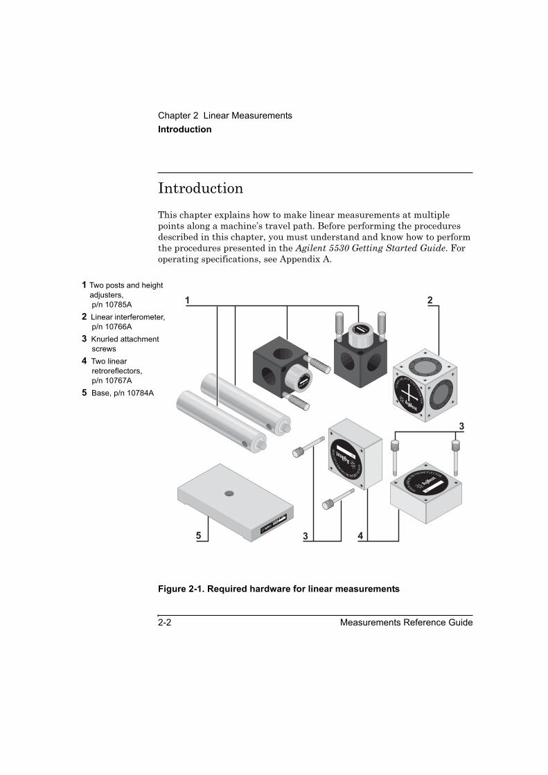
IntroductionThis chapter explains how to make linear measurements at multiple points along a machine’s travel path. Before performing the procedures described in this chapter, you must understand and know how to perform the procedures presented in the Agilent 5530 Getting Started Guide. For operating specifications, see Appendix A.
Figure 2-1. Required hardware for linear measurements
1 Two posts and height adjusters, p/n 10785A
2 Linear interferometer, p/n 10766A
3 Knurled attachment screws
4 Two linear retroreflectors, p/n 10767A
5 Base, p/n 10784A10
76
6ALINEAR INTER
FE
RO
ME
TE
R
10767ALIN
EARRETROREFLECTOR
1A
10785A
HEIG
HT ADJUSTER
A
10785AHEIGHT
ADJU
STER
A
1 2
45
10767ALINEARRETR
OR
EFLE
CTO
R
1A
3
3
2216A10784A B
ASE

Chapter 2 Linear MeasurementsSetting Up for the Measurement
Measurements Reference Guide 2-3
Setting Up for the MeasurementIf you have not already done so, perform the following setup procedures before using the rest of the instructions in this chapter to make a linear measurement. Refer to the Agilent 5530 Getting Started Guide for complete instructions when installing and starting the system for the first time.
1 Mount the laser head on the tripod and place the tripod near the target machine.
2 Connect the E1735A USB Axis Module and the E1736A USB Sensor Hub to the USB connectors on your PC. Connect the laser head and remote control unit to the axis module. Connect the sensors to the sensor hub.
3 Plug in and turn on all equipment.
4 Start the Agilent 10747F Metrology Software.
The Metrology Main Menu is displayed.
5 On the Metrology Main Menu, select Linear.
The Set Up Laser: LINEAR screen (Figure 2-2) is displayed.
Alternately, you can open an existing linear measurement setup file from your database by selecting Recall Data on the Main Menu.
6 Complete the fields on the Set Up Laser: LINEAR screen.
If necessary, use the online help.
Chapter 2 Linear MeasurementsSetting Up for the Measurement
2-4 Measurements Reference Guide
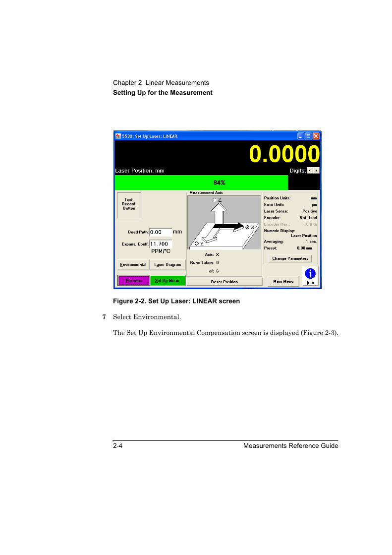
Figure 2-2. Set Up Laser: LINEAR screen
7 Select Environmental.
The Set Up Environmental Compensation screen is displayed (Figure 2-3).
Chapter 2 Linear MeasurementsSetting Up for the Measurement
Measurements Reference Guide 2-5
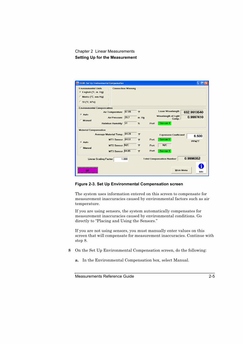
Figure 2-3. Set Up Environmental Compensation screen
The system uses information entered on this screen to compensate for measurement inaccuracies caused by environmental factors such as air temperature.
If you are using sensors, the system automatically compensates for measurement inaccuracies caused by environmental conditions. Go directly to “Placing and Using the Sensors.”
If you are not using sensors, you must manually enter values on this screen that will compensate for measurement inaccuracies. Continue with step 8.
8 On the Set Up Environmental Compensation screen, do the following:
a. In the Environmental Compensation box, select Manual.
Chapter 2 Linear MeasurementsPlacing and Using the Sensors
2-6 Measurements Reference Guide
b. Use the default values or enter new values in the following fields:
• Air Temperature
• Air Pressure
• Relative Humidity
c. In the Material Compensation box, select Manual.
d. Use the default values or enter new values in the following fields:
• Average Material Temp
• Expansion Coefficient
The system saves the values last entered on this screen. It uses them in all linear measurement calculations unless you enter new values or select Auto.
For instructions on completing the other fields on the screen, use the online help.
9 When you have completed the screen, select OK.
You are returned to the Set Up Laser: LINEAR screen.
You are now ready to mount and align the optics on the target machine. Go directly to “Mounting and Aligning the Optics on the Target Machine.”
Placing and Using the SensorsEnvironmental conditions in your work environment affect the accuracy of your linear measurement. These conditions include air temperature, air pressure, relative humidity, and material temperature. The Agilent 5530 uses optional air sensors and material temperature sensors to measure these conditions and adjust the measurements accordingly. If multiple sensors of the same type are used, the software averages their results.
Figure 2-4 shows typical air and material temperature sensors placement in a system.
Chapter 2 Linear MeasurementsPlacing and Using the Sensors
Measurements Reference Guide 2-7
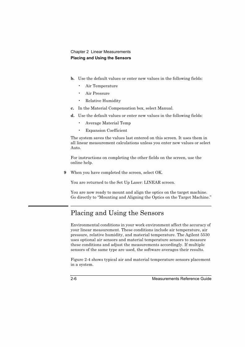
Figure 2-4. Air and material temperature sensors
Before using the following procedure, be sure the air and material temperature sensors are connected to your computer through the USB sensor hub. If they are not connected, refer to the Agilent 5530 Getting Started Guide for instructions.
To automatically adjust for the effects of environmental conditions on the laser reading, follow these steps:
CAUTION In placing the sensors on the machine, be sure the sensors and their cables will not be a hazard to people, will not interfere with your measurement, and will not be damaged by machine movement.
1 Laser head2 Air Sensor3 Material temperature
Sensor* Sensor cables
connected to USB Sensor Hub
3
1 2
3
*
*
*

Chapter 2 Linear MeasurementsPlacing and Using the Sensors
2-8 Measurements Reference Guide
1 Place the air sensor(s) as close as possible to the actual measurement path.
2 Never place an air sensor directly below the laser beam. The sensor is a source of heat and can cause inaccuracies in your measurements. For more information on placing the sensors, refer to the Agilent 5530 Getting Started Guide.
3 Place the material temperature sensors where recommended by calibration standards such as ANSI B-5.
For a machine with a table, it is usually sufficient to place the sensors on the table.
4 On the Set Up Environmental Compensation screen, select Auto in the Environmental Compensation and Material Compensation boxes. Use the default value, or enter a new value in the Expansion Coefficient box.
The sensors now provide the current environmental values to the metrology software. If multiple sensors of the same type are used, the software averages their results.
For instructions on completing the other fields on the screen, use the online help.
5 When you have completed the screen, select OK.
You are returned to the Set Up Laser: LINEAR screen.
You are now ready to mount and align the optics on the target machine.
Chapter 2 Linear MeasurementsMounting and Aligning the Optics on the Target Machine
Measurements Reference Guide 2-9
Mounting and Aligning the Optics on the Target Machine This section explains how to correctly mount and align the interferometer assembly and the separate retroreflector on the target machine before making a measurement.
The figures in this chapter use a machine with a spindle as an example. Although your machine may be different, the general procedures described here still apply.
If angular optics are already mounted on the target machine, you can install the linear optics by simply changing the optics without changing the mounting hardware.
Mounting the opticsTo mount the optics on the target machine, follow these steps:
CAUTION If you are not using the Agilent 5530 to test for machine vibration, then before mounting the optics or making a linear measurement be sure the laser head and the target machine are as stable and free of vibration as possible. Movement of the optics, even from slight vibration, reduces the accuracy of your measurement and may cause the receiver on the laser head to lose beam strength during the measurement.
1 Position the laser head along the axis most suitable for the measurement you want to make (Figure 2-5).
2 Adjust the laser head to the approximate height at which you will mount the optics.
3 Move the moveable part of the target machine as close as possible to the laser head.
This helps prevent the moveable part from hitting the laser head during alignment and measurement procedures.
Chapter 2 Linear MeasurementsMounting and Aligning the Optics on the Target Machine
2-10 Measurements Reference Guide
4 Determine how to position the optics. See Figure 2-5 for sample setups, and use the following guidelines:
• Mount one optic where the tool mounts. Mount the other optic where the work piece mounts. Make sure the interferometer assembly is between the retroreflector and the laser head.
• If you want to measure along an axis perpendicular to the laser beam as it leaves the laser head, mount the interferometer assembly on a part of the machine that does not move.

Chapter 2 Linear MeasurementsMounting and Aligning the Optics on the Target Machine
Measurements Reference Guide 2-11
Figure 2-5. Positioning of linear optics
A Measurement along the X-axis
B Measurement along the Y-axis with the laser beam bent horizontally 90° to the retroreflector
C Measurement along the Z-axis with the laser beam bent vertically 90° to the optics
***********************1 Retroreflector
mounted on a height adjuster with a base and post
2 Interferometer assembly mounted in a spindle
3 Laser beam4 Laser head5 Retroreflector
mounted in a spindle6 Interferometer
assembly mounted on a height adjuster with a base and post
2
2
1
6
5
4
4
4A
B
C
3
3
3
1
Chapter 2 Linear MeasurementsMounting and Aligning the Optics on the Target Machine
2-12 Measurements Reference Guide
5 Attach the interferometer to a retroreflector by following these steps:
Place one retroreflector on the interferometer so one of the arrows on the interferometer’s label points toward the retroreflector (Figure 2-6).
Attach the two optics using the knurled screws included with the retroreflector.
In the rest of this chapter, this assembly made up of the interferometer and the retroreflector is referred to as the “interferometer assembly.”

Chapter 2 Linear MeasurementsMounting and Aligning the Optics on the Target Machine
Measurements Reference Guide 2-13
Figure 2-6. Assembling the interferometer assembly
6 Depending on the axis along which you are measuring, do one of the following:
• Mount the interferometer assembly on the machine table as shown in Figure 2-7. The arrow on the interferometer’s label that does not point to the retroreflector must point to the external reflector; that is, away from the laser head.
1 Knurled screws2 Retroreflector3 Interferometer
1076
6ALINEAR INTER
FE
RO
ME
TE
R
10767ALIN
EARRETROREFLECTOR
1A
1
2
3

Chapter 2 Linear MeasurementsMounting and Aligning the Optics on the Target Machine
2-14 Measurements Reference Guide
• Or, assemble and mount the retroreflector on the machine table as shown in Figure 2-8.
NOTE If you plan on making a straightness or squareness measurement later, position the top of the height adjuster even with the top of the post so you can easily change optics. Then, use the adjustment knobs on the laser head so the return beam enters the laser head’s lower port.
Figure 2-7. Interferometer assembly table mounting
1 Interferometer assembly
2 Height adjuster and post
3 Base4 Laser head
10785A
HE
IGHTADJUSTER
A
1
2
3
4
1076
6ALINEAR INTER
FE
RO
ME
TE
R
10767ALINEARRETROREFL
EC
TOR
1A
Chapter 2 Linear MeasurementsMounting and Aligning the Optics on the Target Machine
Measurements Reference Guide 2-15
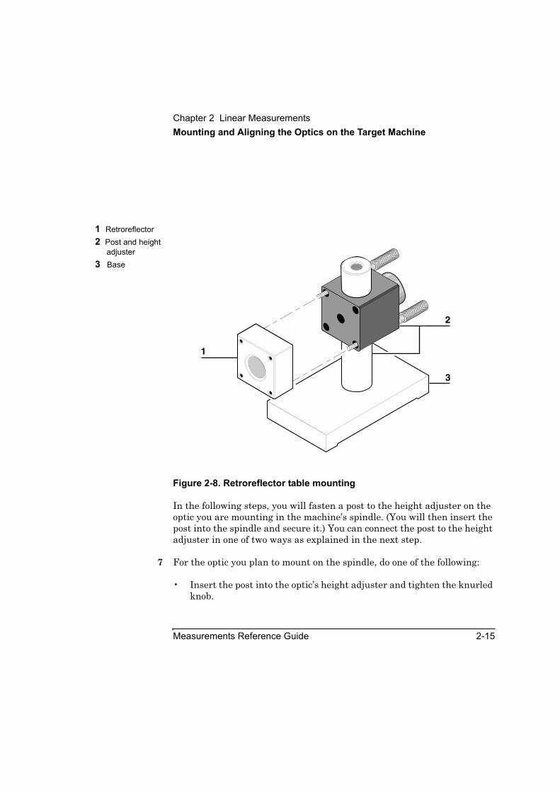
Figure 2-8. Retroreflector table mounting
In the following steps, you will fasten a post to the height adjuster on the optic you are mounting in the machine’s spindle. (You will then insert the post into the spindle and secure it.) You can connect the post to the height adjuster in one of two ways as explained in the next step.
7 For the optic you plan to mount on the spindle, do one of the following:
• Insert the post into the optic’s height adjuster and tighten the knurled knob.
1 Retroreflector2 Post and height
adjuster3 Base
10785A
HE
IGHTADJUSTER
A
1
3
2
Chapter 2 Linear MeasurementsMounting and Aligning the Optics on the Target Machine
2-16 Measurements Reference Guide
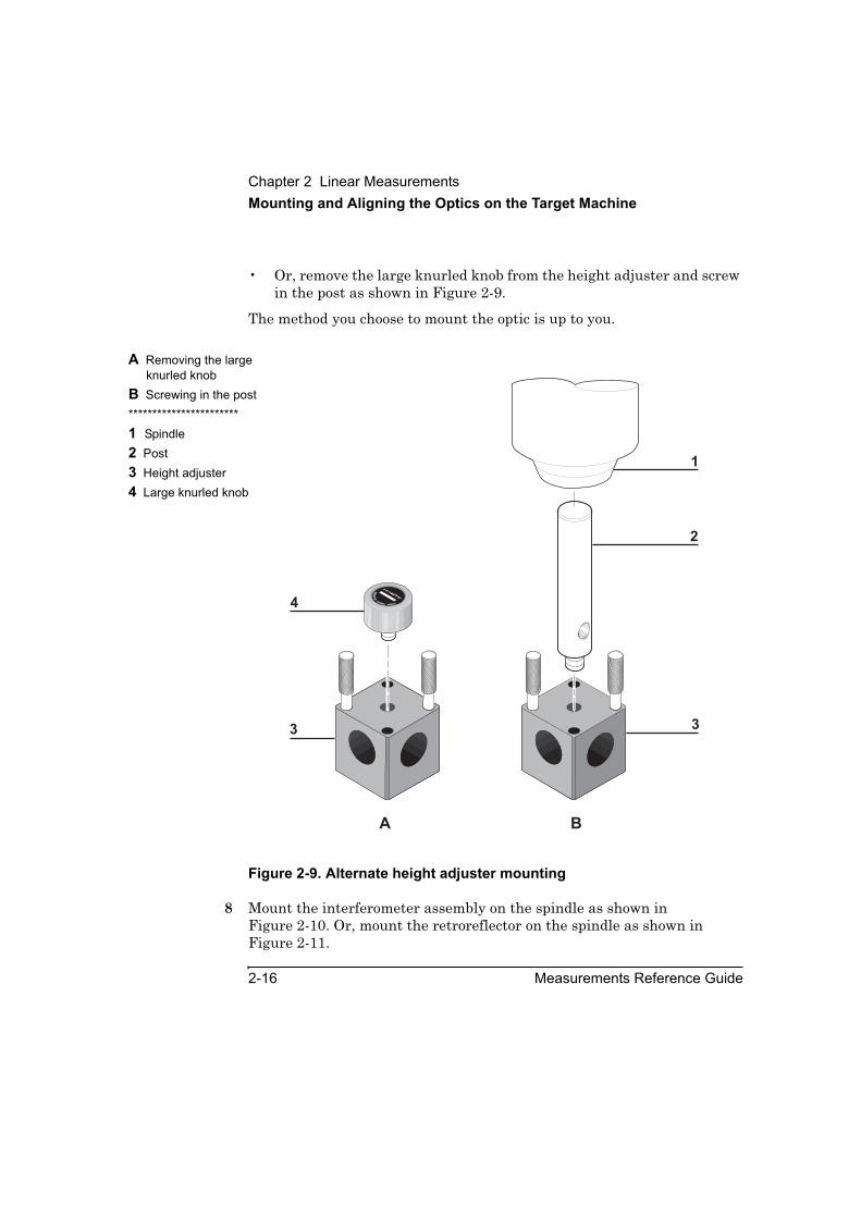
• Or, remove the large knurled knob from the height adjuster and screw in the post as shown in Figure 2-9.
The method you choose to mount the optic is up to you.
Figure 2-9. Alternate height adjuster mounting
8 Mount the interferometer assembly on the spindle as shown in Figure 2-10. Or, mount the retroreflector on the spindle as shown in Figure 2-11.
A Removing the large knurled knob
B Screwing in the post***********************1 Spindle2 Post3 Height adjuster4 Large knurled knob
2
1
3
10785AHEIGHT
ADJU
STER
A
4
3
A B

Chapter 2 Linear MeasurementsMounting and Aligning the Optics on the Target Machine
Measurements Reference Guide 2-17
.
Figure 2-10. Interferometer assembly spindle mounting
1 Post and height adjuster
2 Interferometer assembly
1
10767ALIN
EARRETROREFLECTOR
H E W L E T T - P A CKARD
1A
1076
6ALINEAR INTER
FE
RO
ME
TE
R
2

Chapter 2 Linear MeasurementsMounting and Aligning the Optics on the Target Machine
2-18 Measurements Reference Guide
Figure 2-11. Retroreflector spindle mounting
Although posts, bases, and height adjusters provide considerable adaptability for mounting optics, there may be some situations when you need added flexibility. Figure 2-12 shows how you can increase adaptability by using additional hardware.
1 Post and height adjuster
2 Retroreflector
10785A
HE
IGHTADJUSTER
A
10767ALIN
EAR RETROREFLECTOR
1
2
1
21A

Chapter 2 Linear MeasurementsMounting and Aligning the Optics on the Target Machine
Measurements Reference Guide 2-19
Figure 2-12. Increased mounting adaptability
9 Gently tap each optic with your finger to ensure its mounting is rigid and free of vibration.
If you feel any vibration, tighten all connections in the mounting.
You are now ready to align the optics.
1 C-clamp2 Base3 Post and height
adjuster4 Interferometer or
retroreflector
10785A
HEIG
HT ADJUSTER
A
HEWLETT
-P
AC
KA
R
1076
6ALINEAR INTER
FE
RO
ME
TE
R
10785AHEIGHT
ADJU
STER
A
1 2 3 4
3
Chapter 2 Linear MeasurementsMounting and Aligning the Optics on the Target Machine
2-20 Measurements Reference Guide
Aligning the opticsTo align the optics on the target machine, follow these steps:
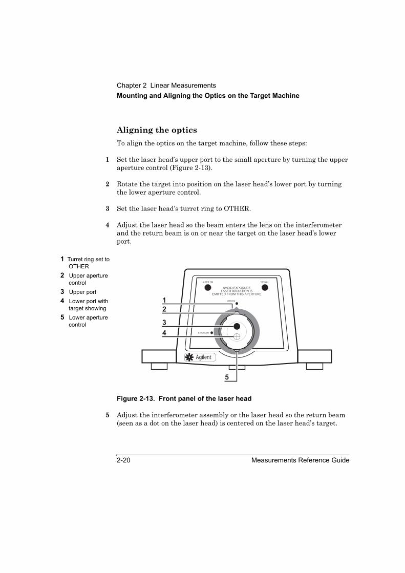
1 Set the laser head’s upper port to the small aperture by turning the upper aperture control (Figure 2-13).
2 Rotate the target into position on the laser head’s lower port by turning the lower aperture control.
3 Set the laser head’s turret ring to OTHER.
4 Adjust the laser head so the beam enters the lens on the interferometer and the return beam is on or near the target on the laser head’s lower port.
Figure 2-13. Front panel of the laser head
5 Adjust the interferometer assembly or the laser head so the return beam (seen as a dot on the laser head) is centered on the laser head’s target.
1 Turret ring set to OTHER
2 Upper aperture control
3 Upper port4 Lower port with
target showing5 Lower aperture
controlSTRAIGHT
AVOID EXPOSURELASER RADIATION IS
EMITTED FROM THIS APERTURE
LASER ON SIGNAL
OTHER
4
5
3
2
1
Agilent

Chapter 2 Linear MeasurementsMounting and Aligning the Optics on the Target Machine
Measurements Reference Guide 2-21
To adjust the interferometer up or down, loosen the large knob on the height adjuster, move the interferometer up or down, then tighten the knob. You can also move the interferometer left or right or rotate it left or right.
You can adjust the laser head by rotating it, translating it, or both.
6 Secure the interferometer assembly to the target machine, maintaining the laser beam’s position in the center of the laser head’s target.
To secure the interferometer assembly, use a clamp or similar device. Observe the following guidelines when securing the interferometer assembly:
• If you are securing the optic to the spindle, lock the spindle in place.
• If you are securing the optic to a surface such as a machine table, make sure the surface is flat so the optic will not rock.
• When using a clamp to secure the optic, try to cover as much of the optic’s base as possible with the clamp so the attachment is secure.
NOTE It is helpful to orient the lines visible in the window of the retroreflector as shown in Figure 2-14. If they are not, the retroreflector will absorb light from the laser rather than reflect the light. This renders the return dots fuzzy and makes alignment more difficult. If you need to reorient the retroreflector, follow these steps:
1. Remove the retroreflector from the height adjuster.
2. Rotate the retroreflector 90 degrees in either direction.
3. Reattach the retroreflector to the height adjuster.

Chapter 2 Linear MeasurementsMounting and Aligning the Optics on the Target Machine
2-22 Measurements Reference Guide
Figure 2-14. Correct retroreflector orientation
7 Move the retroreflector as close as possible to the interferometer assembly without allowing the two to touch. Less than 25 mm (1 inch) is preferred. Then, adjust the retroreflector so its return beam is centered on the target covering the laser head’s return port and overlays the interferometer return beam.
In the rest of this chapter, the position of the retroreflector near the interferometer assembly as described above is referred to as the “start position.”
NOTE To perform an alignment when the two optics are close together like this, adjust the optics only, not the laser head. Adjust the laser head only when the optics have been moved apart.
1 Correct orientation of internal lines
2 Retroreflector
2
1
HEWLETT-PA
CK
AR
D 10785A
HE
IGHTADJUSTER
A
Chapter 2 Linear MeasurementsAligning the Laser Beam to the Machine’s Travel Path for Long-Range Measurements
Measurements Reference Guide 2-23
8 Secure the retroreflector to the target machine, maintaining its return beam’s position in the center of the laser head’s target.
See the guidelines for securing an optic listed in step 6.
You are now ready to align the laser beam to the machine’s travel path.
If your measurement distance is less than 350 mm (14 inches), go directly to “Aligning the Laser Beam to the Machine’s Travel Path for Short-Range Measurements.”
If your measurement distance is greater than 350 mm (14 inches), continue with the next section, “Aligning the Laser Beam to the Machine’s Travel Path for Long-Range Measurements.”
Aligning the Laser Beam to the Machine’s Travel Path for Long-Range MeasurementsUse this procedure if your measurement distance is greater than 350 mm (14 inches). Before proceeding, make sure the machine is at the start position. To align the laser beam to the machine’s travel path, follow these steps:
1 While watching the return beam on the laser head, move the machine’s moveable part away from the laser head.
If the retroreflector’s dot moves away from the target cross hairs on the laser head, the laser beam is not aligned with the travel path. Continue with step 2.
If the dot does not move by the time the moveable part reaches the last measurement point, the laser beam is already aligned with the travel path. Skip the rest of these steps and go directly to “Making the Measurement.”

Chapter 2 Linear MeasurementsAligning the Laser Beam to the Machine’s Travel Path for Long-Range Measurements
2-24 Measurements Reference Guide
2 Make the following adjustments:
a. Carefully tilt the laser head up or down until the dot moves vertically twice the distance in the opposite direction it moved when you performed step 1.
For example, if the dot moved 25 mm (1 inch) below the target when you moved the machine’s moveable part, adjust the laser head until the dot is 25 mm (1 inch) above the target.
b. Carefully rotate the laser head left or right until the dot moves horizontally twice the distance in the opposite direction it moved when you performed step 1.
3 Move the machine’s moveable part back to its start position.
Usually, the dot will now be partially or completely off the target cross hairs.
4 Translate the laser head up or down and left or right until:
• the beam from the laser head completely enters the interferometer’s lens, and
• both dots overlap the cross hairs on the laser head’s target.
5 Repeat steps 1 through 4 until the machine’s moveable part reaches the last measurement point or the dots no longer move from their position on the cross hairs.
You are now ready to make the measurement. Go directly to “Making the Measurement.”
Chapter 2 Linear MeasurementsAligning the Laser Beam to the Machine’s Travel Path for Short-Range Measurements
Measurements Reference Guide 2-25
Aligning the Laser Beam to the Machine’s Travel Path for Short-Range MeasurementsUse this procedure if your measurement distance is less than 350 mm (14 inches). Before proceeding, make sure the machine is at the start position and the small aperture is in position over the upper port on the laser head. To align the laser beam to the machine’s travel path, follow these steps:
1 Place a reference mirror or a similar reflecting device between the interferometer and retroreflector.
2 Make sure the reflecting device you use:
• is aligned so its reflecting surface is perpendicular to the machine’s travel path, and
• reflects the beam parallel to the machine’s travel path back to the upper port on the laser head.
If you use a reference mirror and the machine has T slots, you can align the reference mirror so it is parallel to the T slots.
3 Tilt the laser head up or down and rotate it left or right until the return beam from the reference mirror forms a halo around the aperture in the upper port.
You are now ready to make the linear measurement.
Chapter 2 Linear MeasurementsMaking the Measurement
2-26 Measurements Reference Guide
Making the Measurement In this procedure, you make manual measurements as you move the machine’s moveable part. If you are using sensors, make sure they are properly placed and the software is set up correctly. (Refer to the Agilent 5530 Getting Started Guide for complete instructions on using the software and the sensors.)
This procedure explains how to make measurements using the Record button in the software and the optional remote control unit. See Chapter 1, “Planning Your Measurements,” for a description of other triggering methods.
To make the measurement, follow these steps:
1 Move the moveable optic so it is at its start position.
2 On the Set Up Laser: LINEAR screen, select Set Up Meas.
The Set Up Measurement: LINEAR screen is displayed (Figure 2-15).
Chapter 2 Linear MeasurementsMaking the Measurement
Measurements Reference Guide 2-27
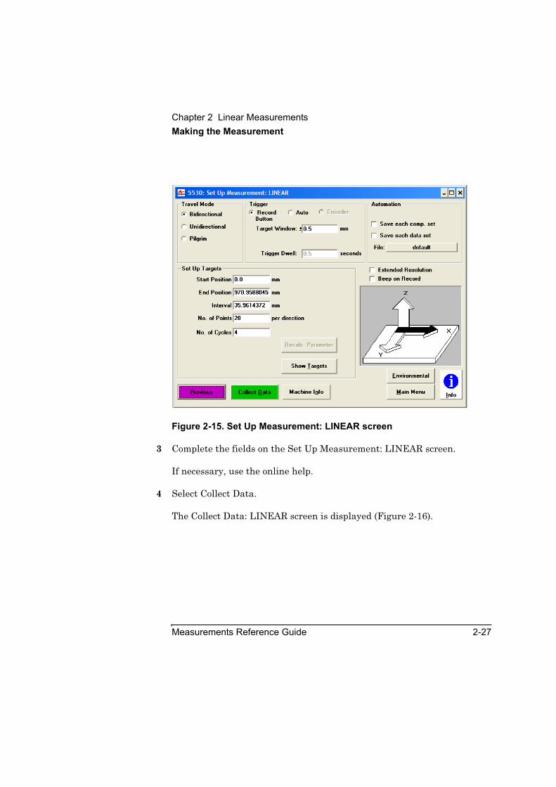
Figure 2-15. Set Up Measurement: LINEAR screen
3 Complete the fields on the Set Up Measurement: LINEAR screen.
If necessary, use the online help.
4 Select Collect Data.
The Collect Data: LINEAR screen is displayed (Figure 2-16).
Chapter 2 Linear MeasurementsMaking the Measurement
2-28 Measurements Reference Guide
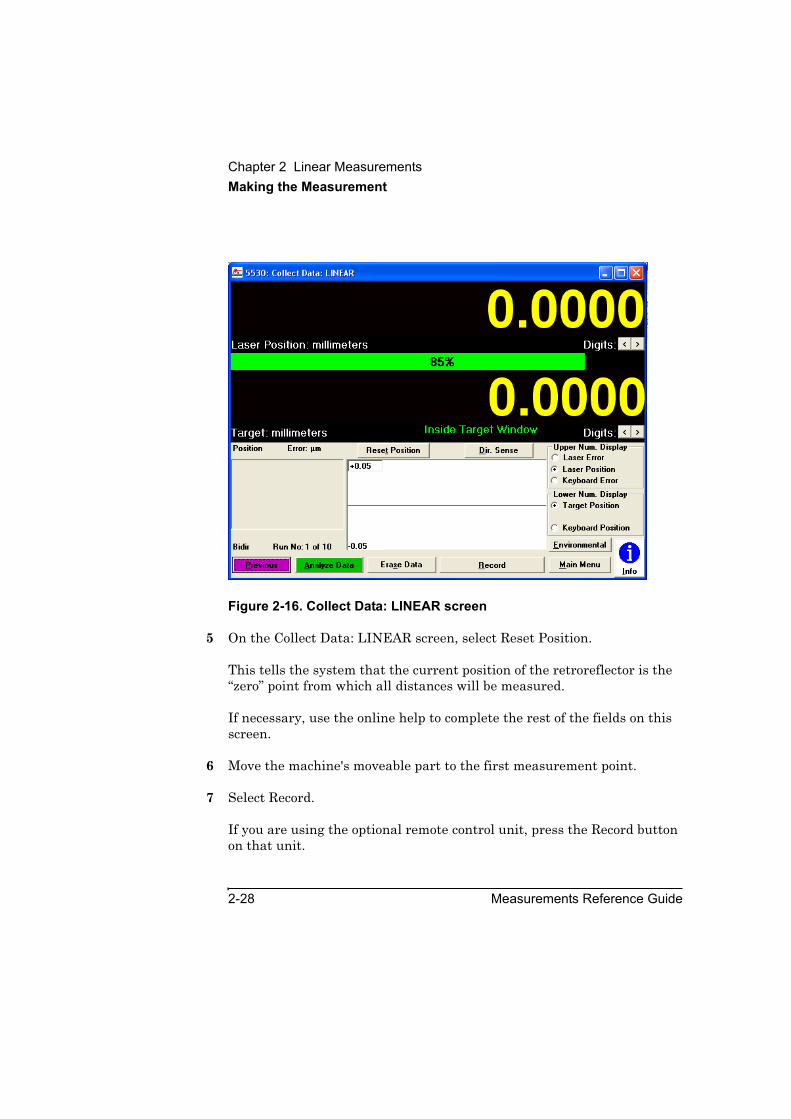
Figure 2-16. Collect Data: LINEAR screen
5 On the Collect Data: LINEAR screen, select Reset Position.
This tells the system that the current position of the retroreflector is the “zero” point from which all distances will be measured.
If necessary, use the online help to complete the rest of the fields on this screen.
6 Move the machine's moveable part to the first measurement point.
7 Select Record.
If you are using the optional remote control unit, press the Record button on that unit.

Chapter 2 Linear MeasurementsMaking the Measurement
Measurements Reference Guide 2-29
8 Continue moving the machine’s moveable part to each point and recording measurements until the machine has reached the last measurement position.
NOTE If at any point the Reset Laser message flashes, the laser beam path has been broken. Move the retroreflector back to the last position measured before the beam was broken, then select Reset Laser to reset the system.
After you record the last measurement, the Analyze Data: LINEAR screen is displayed (Figure 2-17).
Figure 2-17. Analyze Data: LINEAR screen
9 On the Analyze Data: LINEAR screen, select Save Data to create or update a data file with the measurement data.
Refer to the Agilent 5530 Getting Started Guide and online help for more information about using this screen. Otherwise, you are finished making the measurement.

Chapter 2 Linear MeasurementsMaking the Measurement
2-30 Measurements Reference Guide

3
Timebase Measurements
Chapter 3 Timebase MeasurementsIntroduction
3-2 Measurements Reference Guide
IntroductionThis chapter explains how to make timebase-triggered linear, angular, and straightness measurements. With timebase measurements you can determine the position, velocity, and acceleration of these variables as a function of time.
Timebase measurement data can assist you in deciding if your machine tools perform accurately. For example, you can determine how to properly tune servo drives and make necessary mechanical adjustments by analyzing the following elements:
• linear velocity profile and constant-velocity measurements
• feed rate adjustment
• relative vibrations (linear, angular, and straightness)
• “torque profile” (angle of rotation as a stage or gantry starts or stops rapidly)
Timebase measurement data is also helpful in machine drift testing. As you make measurements, you can create your own uses and applications for timebase measurements.
Because setup, optics mounting, and alignment procedures for timebase measurements are the same as those for other linear, angular, and straightness measurements, you are referred to the following chapters for most instructions: Chapter 2, “Linear Measurements,” Chapter 4, “Angular Measurements,” and Chapter 5, “Straightness Measurements.”
Before performing the procedures described in this chapter, you must fully understand and know how to perform the procedures presented in the Agilent 5530 Getting Started Guide.

Chapter 3 Timebase MeasurementsSetting Up for the Measurement
Measurements Reference Guide 3-3
Setting Up for the MeasurementIf you have not done so, perform the following setup procedures before using the rest of the instructions in this chapter to make a timebase measurement. Refer to the Agilent 5530 Getting Started Guide for complete instructions when installing and starting the system for the first time.
1 Mount the laser head on the tripod and place the tripod near the target machine.
2 Connect the E1735A USB Axis Module and the E1736A USB Sensor Hub to the USB connectors on your PC. Connect the laser head and remote control unit to the axis module. Connect the sensors to the sensor hub.
3 Plug in and turn on all equipment.
4 Start the Agilent 10747F Metrology Software.
The Metrology Main Menu is displayed.
5 On the Metrology Main Menu, select Other Meas.
The Other Measurements screen is displayed (Figure 3-1).
Or, you can open an existing timebase setup file by selecting Recall Data on the Main Menu.
Chapter 3 Timebase MeasurementsSetting Up for the Measurement
3-4 Measurements Reference Guide
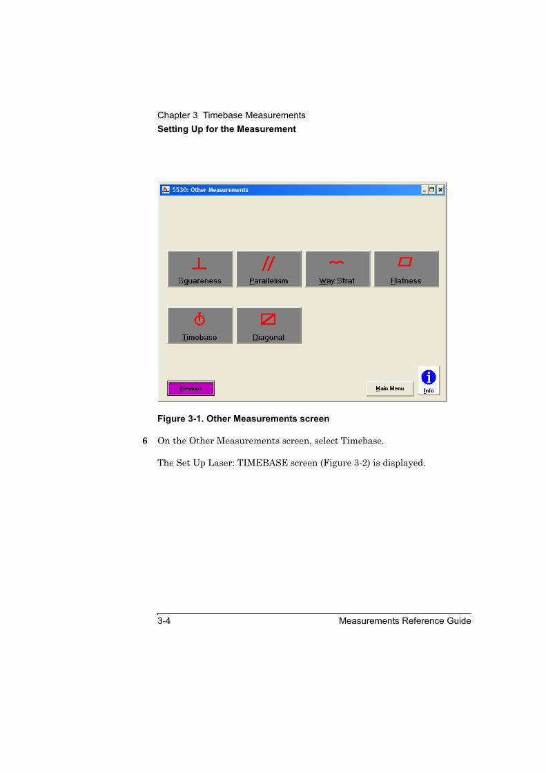
Figure 3-1. Other Measurements screen
6 On the Other Measurements screen, select Timebase.
The Set Up Laser: TIMEBASE screen (Figure 3-2) is displayed.
Chapter 3 Timebase MeasurementsSetting Up for the Measurement
Measurements Reference Guide 3-5
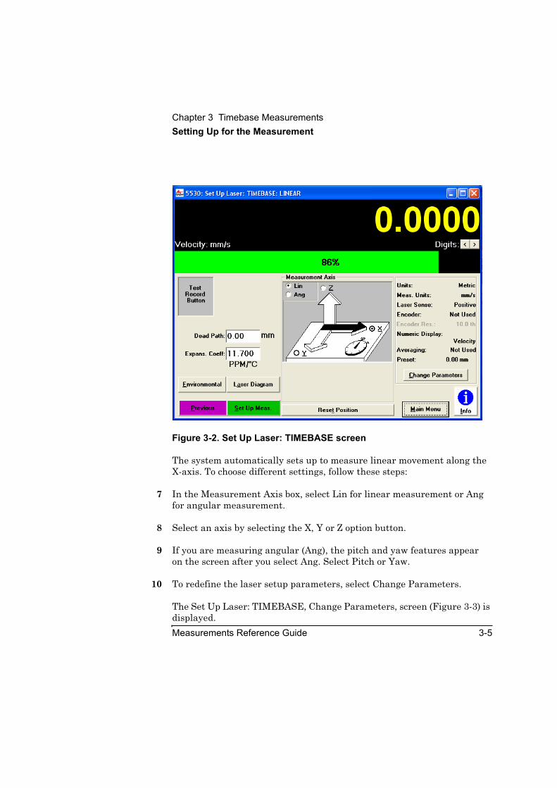
Figure 3-2. Set Up Laser: TIMEBASE screen
The system automatically sets up to measure linear movement along the X-axis. To choose different settings, follow these steps:
7 In the Measurement Axis box, select Lin for linear measurement or Ang for angular measurement.
8 Select an axis by selecting the X, Y or Z option button.
9 If you are measuring angular (Ang), the pitch and yaw features appearon the screen after you select Ang. Select Pitch or Yaw.
10 To redefine the laser setup parameters, select Change Parameters.
The Set Up Laser: TIMEBASE, Change Parameters, screen (Figure 3-3) is displayed.

Chapter 3 Timebase MeasurementsSetting Up for the Measurement
3-6 Measurements Reference Guide
Figure 3-3. Set Up Laser: TIMEBASE, Change Parameters screen
If necessary, use the online help.
NOTE The following options are not available for timebase measurements: encoder, averaging, and extended resolution.
If you selected linear, complete the Set Up Environmental Compensation screen following steps 7 through 9 in “Setting Up for the Measurement” in Chapter 2.
If you selected straightness, complete the instructions in “Positioning the Laser Head and Target Machine” in Chapter 5.
You are now ready to mount and align the optics on the target machine; continue with the next section.
Chapter 3 Timebase MeasurementsMounting and Aligning the Optics on the Target Machine
Measurements Reference Guide 3-7
Mounting and Aligning the Optics on the Target MachineFor linear measurements, complete the instructions in “Mounting and Aligning the Optics on the Target Machine” in Chapter 2.
For angular measurements, complete the instructions in “Mounting and Aligning the Optics on the Target Machine” in Chapter 4.
For straightness measurements, complete the instructions in “Mounting and Aligning Optics for X-Axis or Y-Axis Measurements” in Chapter 5.
You are now ready to align the laser beam to the machine’s travel path; continue with the next section.
Aligning the Laser Beam to the Machine’s Travel PathFor linear measurements, complete the instructions in “Aligning the Laser Beam to the Machine’s Travel Path for Long-Range Measurements” in Chapter 2 if your measurement is 350 mm (14 inches) or more. If your measurement distance is less than 350 mm (14 inches), follow the instructions in “Aligning the Laser Beam to the Machine’s Travel Path for Short-Range Measurements” in Chapter 2.
For angular measurements, complete the instructions in “Aligning the Laser Beam to the Machine’s Travel Path for Short-Range Measurements” in Chapter 2 regardless of the length of your measurement.
For straightness measurements, complete the instructions in “Aligning the Laser Beam to the Machine’s Travel Path” and “Checking the Alignment for Beam Strength” in Chapter 5.
You are now ready to make a timebase measurement; continue with the next section.
Chapter 3 Timebase MeasurementsMaking the Measurement
3-8 Measurements Reference Guide
Making the MeasurementThis section explains how to make a timebase measurement. If you are using sensors, make sure they are properly placed and the software is set up properly. (Refer to the Agilent 5530 Getting Started Guide for complete instructions on using the software and the sensors.)
To make a timebase measurement, follow these steps:
1 Place the moveable optic at its starting position.
2 On the Set Up Laser: TIMEBASE screen, select Set Up Meas.
The Set Up Measurement: TIMEBASE screen is displayed (Figure 3-4).

Chapter 3 Timebase MeasurementsMaking the Measurement
Measurements Reference Guide 3-9
Figure 3-4. Set Up Measurement: TIMEBASE screen
3 Complete the fields on the Set Up Measurement: TIMEBASE screen as follows:
a. To change the Sample Interval value, highlight the numbers you want to change and enter the new value.
This field specifies the time between two consecutive samples of laser position. For a slow machine tool movement, make sure the sample interval is long enough to collect an adequate amount of data. For a fast machine tool movement, make sure the sample interval is short enough to capture all changes. If necessary, see the online help to determine the range of values.
b. In the Start Timer box, specify the starting conditions from the choices available for your measurement.

Chapter 3 Timebase MeasurementsMaking the Measurement
3-10 Measurements Reference Guide
Record Button enables you to use either the remote control unit’s Record button or the Collect Data: TIMEBASE screen’s Start Timer button.
You may specify a threshold laser position value that the machine must cross in either direction in order to start the timer and begin collecting data via the Start Position field. When you choose Position, the Collect Data: TIMEBASE screen’s timer control button is labeled Arm Timer.
NOTE Position can only be used for linear measurements.
c. In the Stop Timer box, specify the ending conditions from the choices available for your measurement.
Record Button is similar in function to that described for the Start Timer box in step 3b. However, note that the Collect Data: TIMEBASE screen’s timer control button is labeled Stop Timer.
NOTE Regardless of the Stop Timer condition you selected on the Set Up Measurement: TIMEBASE screen, the remote control unit’s record button will always stop a measurement in progress. This is useful in case your specified Stop Timer condition is not met in a timely manner.
Exiting from the Collect Data: TIMEBASE screen will also stop a measurement.
Position is similar in function to that described for the Start Timer box in step 3b. However, note that you use the Stop Position field and that the Collect Data: TIMEBASE screen’s timer control button is labeled Stop Timer.
Total time requires you to specify the total time for your measurement in the Stop Position field.
No. of Points requires you to specify the number of position samples to be taken for a complete measurement.
d. In the Automation box you can choose to save each data set. This automatically saves data at the end of each complete measurement. Specify the file into which the data will be saved. Refer to the online

Chapter 3 Timebase MeasurementsMaking the Measurement
Measurements Reference Guide 3-11
help for more information. If the specified file already exists, the new data will replace it.
e. If you want to display or change information about your machine, select Machine Info.
4 When you have finished with the Set Up Measurement: TIMEBASE screen, select Collect Data.
The Collect Data: TIMEBASE screen is displayed (Figure 3-5).
Figure 3-5. Collect Data: TIMEBASE screen
Chapter 3 Timebase Measurements
Making the Measurement
3-12 Measurements Reference Guide
5 Complete the fields on the Collect Data: TIMEBASE screen.
If necessary, use the online help to complete these fields.
6 On the Collect Data: TIMEBASE screen, select Reset Position.
This tells the system that the current position of the reflector is the “zero” point from which all distances will be measured.
If necessary, use the online help to complete the rest of the fields on this screen.
NOTE If at any point the Reset Laser message flashes, the laser beam path has been broken. The system treats this as a Stop Timer condition. It exits from the Collect Data: TIMEBASE screen to the Analyze Data: TIMEBASE screen and analyzes the data it has taken. You cannot resume the interrupted measurement. Return the machine and measurement optics to the starting position and then restart the measurement.
7 Select the Start Timer or Arm Timer button or press the record button on your remote control unit.
This tells the system to clear the graph. The lower numeric display is set to zero. If Record Button was specified for Start Timer on the Set Up Measurement: TIMEBASE screen, the timer and data collection will start immediately. Otherwise, the timer is held off until the specified starting position is reached or crossed.
The timer stops automatically when the Stop Timer condition specified on the Set Up Measurement: TIMEBASE screen is met.
You can also stop the timer by performing one of the following actions:
• Press the Collect Data: TIMEBASE screen’s Stop Timer button.
• Exit from the Collect Data: TIMEBASE screen.
• Press the record button on the remote control unit.
8 On the Collect Data: TIMEBASE screen, select Analyze Data.
Chapter 3 Timebase MeasurementsAnalyzing Timebase Measurement Data
Measurements Reference Guide 3-13
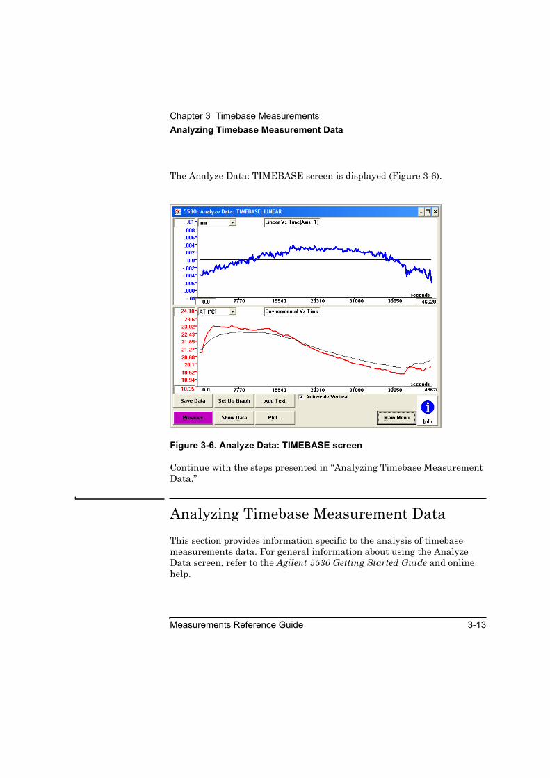
The Analyze Data: TIMEBASE screen is displayed (Figure 3-6).
Figure 3-6. Analyze Data: TIMEBASE screen
Continue with the steps presented in “Analyzing Timebase Measurement Data.”
Analyzing Timebase Measurement DataThis section provides information specific to the analysis of timebase measurements data. For general information about using the Analyze Data screen, refer to the Agilent 5530 Getting Started Guide and online help.
Chapter 3 Timebase MeasurementsAnalyzing Timebase Measurement Data
3-14 Measurements Reference Guide
Displaying timebase measurement dataBased on how you set up your measurement and what you select on the Set Up Graph: TIMEBASE screen, the Analyze Data: TIMEBASE screen presents laser and environmental data shown on separate graphs and tables.
If you are using sensors, the Analyze Data: TIMEBASE screen displays two areas:
• The top half of the screen displays a laser graph. This graph automatically shows the position of the machine tool (represented by a blue trace on color monitors and by a solid line on monochrome monitors). The horizontal axis of the graph always represents time; the vertical axis represents the measurement type (linear, angular, or straightness).
• The bottom half of the screen displays environmental data on a graph.
Use the Set Up Graph: TIMEBASE screen to specify additional analysis to be plotted on the graphs. For example, to add velocity and acceleration to the laser graph in Figure 3-6, follow these steps:
1 On the Analyze Data: TIMEBASE screen, select Set Up Graph.
The Set Up Graph: TIMEBASE screen (Figure 3-7) is displayed.

Chapter 3 Timebase MeasurementsAnalyzing Timebase Measurement Data
Measurements Reference Guide 3-15
Figure 3-7. Set Up Graph: TIMEBASE screen
2 In the LASER box, select one or more of the choices available.
This tells the system which data to graph. If you want the trace identification to be included on the graph, select Show Legend in the Plot Annotation box.
3 In the ENVIRONMENTAL box, select the data to graph.
Environmental data entered manually in the Set Up Laser: TIMEBASE screen is not graphed or displayed in the Show Data Set: TIMEBASE screen.
4 In the Stats (Statistics) box, select any additional numeric information you want for your laser or environmental data.
Chapter 3 Timebase MeasurementsAnalyzing Timebase Measurement Data
3-16 Measurements Reference Guide
5 In the Plot Annotation box, select any additional information you want to show on your graph.
Use the online help for more information about these choices.
6 If you want to display or change information about your machine, select Machine Info.
7 Select Previous to return to the Analyze Data: TIMBEBASE screen.
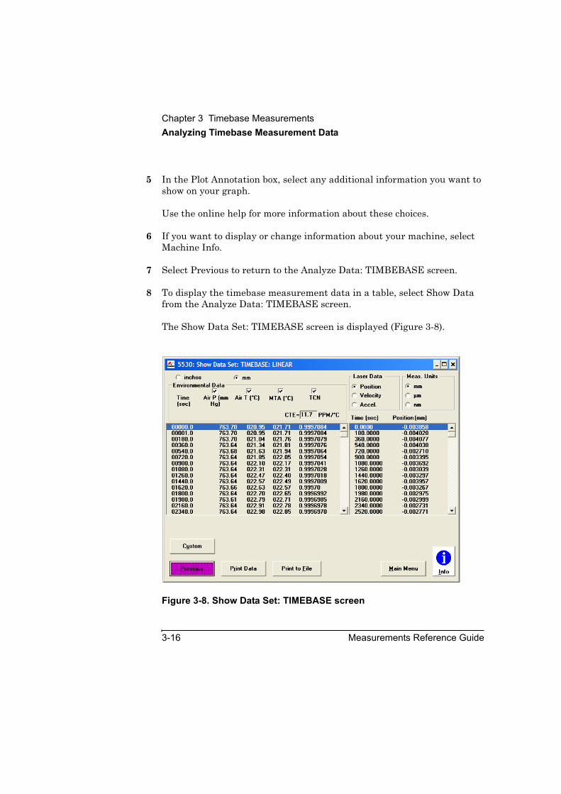
8 To display the timebase measurement data in a table, select Show Data from the Analyze Data: TIMEBASE screen.
The Show Data Set: TIMEBASE screen is displayed (Figure 3-8).
Figure 3-8. Show Data Set: TIMEBASE screen

Chapter 3 Timebase MeasurementsAnalyzing Timebase Measurement Data
Measurements Reference Guide 3-17
Refer to the online help for more information about using the Show Data Set: TIMEBASE screen. Otherwise, you are finished making the measurement.
Understanding timebase measurement dataWhen you make timebase measurements with the Agilent 5530, keep in mind the following mathematical formulas that express velocity and acceleration:
Velocity is the change in position (Dx = x2 − x1) per unit time interval (Dt = t2 − t1), expressed as follows:
v1 = Dx / Dt = (x2 − x1) / (t2 − t1)
On the Analyze Data: TIMEBASE screen, velocity is plotted midway between the position points. For example, the first velocity point v1 is plotted midway between t1 and t2. Note that what you measure with the Agilent 5530 is the average velocity during a specified time interval.
Acceleration is the change in velocity (Dv = v2 − v1) per unit time interval (Dt = t2 − t1), expressed as follows:
a2 = (Dv / Dt) = (v2 - v1) / Dt
Using the equation for velocity, you can also express acceleration as follows:
a2 = ((x3 − x2) - (x2 − x1)) / (Dt)2 = (x3 - 2x2 + x1) / (Dt)2
On the Analyze Data: TIMEBASE screen, acceleration is plotted midway between the velocity points. For example, the first acceleration point a2 is plotted at t2.
NOTE Position may be linear, angular, or straightness. The corresponding velocity and acceleration are linear, angular, or straightness.

Chapter 3 Timebase MeasurementsAnalyzing Timebase Measurement Data
3-18 Measurements Reference Guide

4
Angular Measurements

Chapter 4 Angular MeasurementsIntroduction
4-2 Measurements Reference Guide
IntroductionThis chapter explains how to make pitch, yaw, or angular position measurements.
Pitch or yaw measurements are made by making angular measurements at multiple points along a machine’s (linear) travel path.
Angular position (Angle) measurements are performed by making angular measurements at multiple points as the device being measured is rotated. Angular position measurements may require additional fixturing not required for pitch or yaw measurements. Also, the procedures are different from those for pitch or yaw measurements. Instructions for making an angular position measurement are given later in this chapter, following those for pitch or yaw measurements.
Before performing the procedures described in this chapter, you must understand and know how to perform the procedures presented in the Agilent 5530 Getting Started Guide.
For operating specifications, see Appendix A.
Figure 4-1 shows the required optics and hardware for angular (pitch or yaw) measurements.
Chapter 4 Angular MeasurementsIntroduction
Measurements Reference Guide 4-3
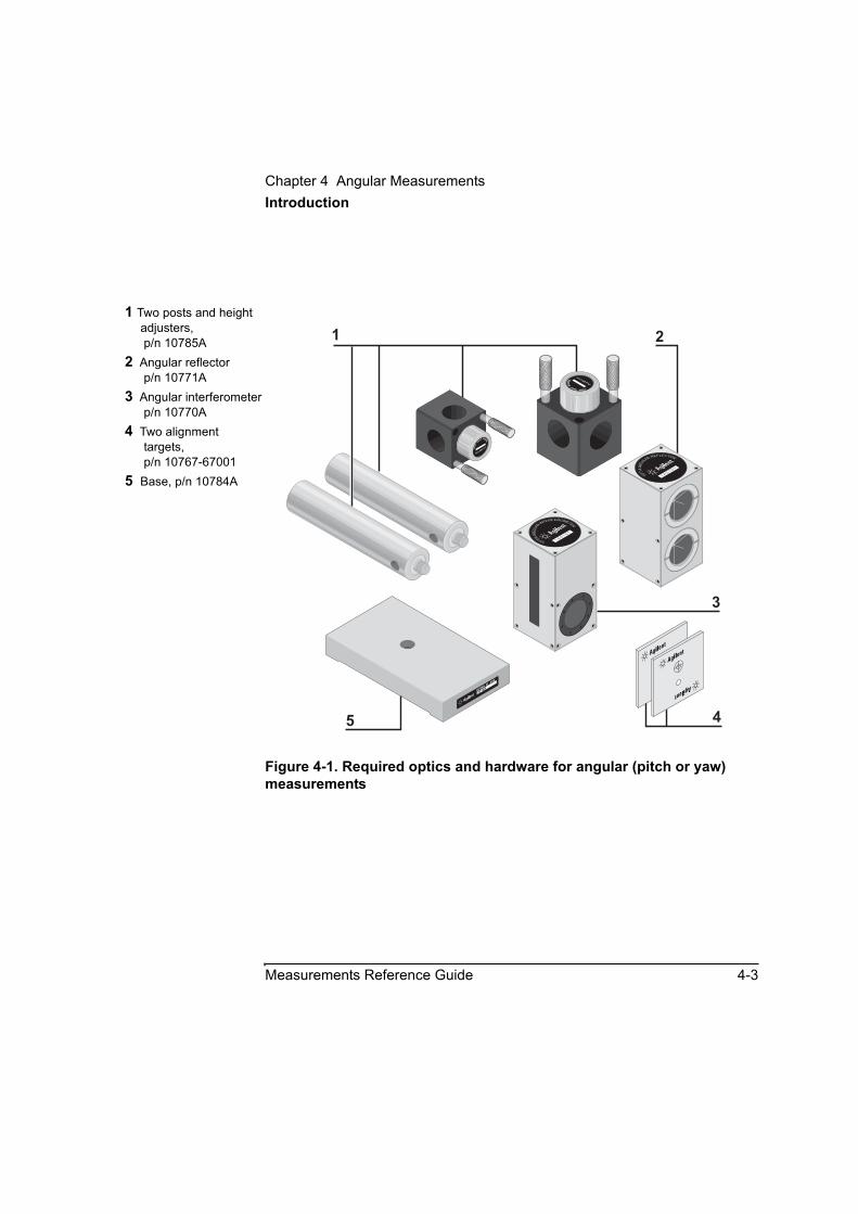
Figure 4-1. Required optics and hardware for angular (pitch or yaw) measurements
1 Two posts and height adjusters, p/n 10785A
2 Angular reflector p/n 10771A
3 Angular interferometer p/n 10770A
4 Two alignment targets, p/n 10767-67001
5 Base, p/n 10784A
2216A10784A B
ASE
10785AHEIGHT
ADJU
STER
A
1 2
3
5 4
10785A
HEIG
HT ADJUSTER
10771A
ANGU
LARREFLECTOR
1 A0 1
0 1
10770A
ANGU
LA
R INTE
RFEROMETER
1 A0 1
0 1

Chapter 4 Angular MeasurementsSetting Up for a Pitch or Yaw Measurement
4-4 Measurements Reference Guide
Setting Up for a Pitch or Yaw MeasurementIf you have not already done so, perform the following setup procedures before using the rest of the instructions in this chapter. Refer to the Agilent 5530 Getting Started Guide for complete instructions when installing and starting the system for the first time.
1 Mount the laser head on the tripod and place the tripod near the target machine.
2 Connect the E1735A USB Axis Module and the E1736A USB Sensor Hub to the USB connectors on your PC. Connect the laser head and remote control unit to the axis module. Connect the sensors to the sensor hub.
3 Plug in and turn on all equipment.
4 Start the Agilent 10747F Metrology Software.
The Metrology Main Menu is displayed.
5 On the Metrology Main Menu, select Angular.
The Set Up Laser: ANGULAR screen (Figure 4-2) is displayed.
Alternately, you can open an existing angular measurement setup file from your database by selecting Recall Data on the Main Menu.
Chapter 4 Angular MeasurementsSetting Up for a Pitch or Yaw Measurement
Measurements Reference Guide 4-5
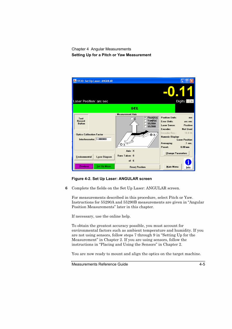
Figure 4-2. Set Up Laser: ANGULAR screen
6 Complete the fields on the Set Up Laser: ANGULAR screen.
For measurements described in this procedure, select Pitch or Yaw. Instructions for 55290A and 55290B measurements are given in “Angular Position Measurements” later in this chapter.
If necessary, use the online help.
To obtain the greatest accuracy possible, you must account for environmental factors such as ambient temperature and humidity. If you are not using sensors, follow steps 7 through 9 in “Setting Up for the Measurement” in Chapter 2. If you are using sensors, follow the instructions in “Placing and Using the Sensors” in Chapter 2.
You are now ready to mount and align the optics on the target machine.
Chapter 4 Angular MeasurementsMounting and Aligning the Optics on the Target Machine
4-6 Measurements Reference Guide
Mounting and Aligning the Optics on the Target MachineThis section explains how to correctly mount and align the interferometer and reflector on the target machine before making a pitch or yaw measurement.
NOTE • If linear optics are already mounted on the target machine, you can install the angular optics by simply changing the optics without changing the mounting hardware (Figures 4-3 and 4-4).
• Changes in the interferometer’s or the reflector’s temperature willaffect the accuracy of your measurements. To minimize this problem,(1) avoid excessive handling of the optics, and (2) keep the optics away from sources of heat and cold, such as air vents.
Mounting the opticsTo mount the optics on the target machine, follow these steps:
CAUTION Before mounting the optics or making an angular measurement, be sure the laser head and the target machine are as stable and free of vibration as possible. Movement of the optics, even from slight vibration, reduces the accuracy of your measurement and may cause the receiver on the laser head to lose beam strength during a measurement.
1 Position the laser head along the axis most suitable for the measurement that you want to make (Figures 4-3 and 4-4).
2 Adjust the laser head to the approximate height at which you will mount the optics.
3 Move the moveable part of the target machine as close as possible to the laser head.
Chapter 4 Angular MeasurementsMounting and Aligning the Optics on the Target Machine
Measurements Reference Guide 4-7
This helps prevent the moveable part from hitting the laser head during the alignment and measurement procedures.
4 Determine how to position the optics. See Figures 4-3 and 4-4 for sample setups, and use the following guidelines:
• Figures 4-3 and 4-4 show optic setups and positioning for a machine with a table top as the moving part. If the spindle is the moving part, the angular reflector must be mounted on it and the angular interferometer must be mounted on the table between the laser head and the angular reflector.
• Mount one optic where the tool mounts. Mount the other optic where the work piece mounts. Make sure the interferometer is between the reflector and the laser head.
• If you want to measure along an axis perpendicular to the laser beam as it leaves the laser head, mount the interferometer on a part of the machine that remains stationary.
Chapter 4 Angular MeasurementsMounting and Aligning the Optics on the Target Machine
4-8 Measurements Reference Guide
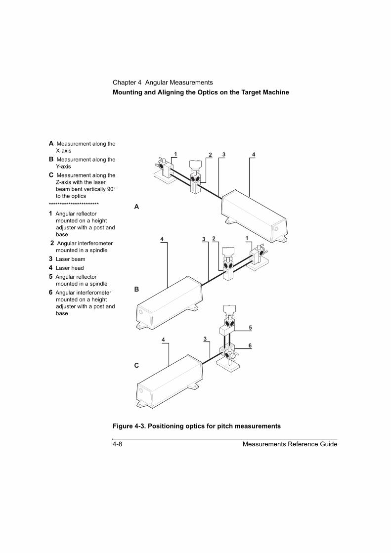
Figure 4-3. Positioning optics for pitch measurements
A Measurement along the X-axis
B Measurement along the Y-axis
C Measurement along the Z-axis with the laser beam bent vertically 90° to the optics
***********************1 Angular reflector
mounted on a height adjuster with a post and base
2 Angular interferometer mounted in a spindle
3 Laser beam4 Laser head5 Angular reflector
mounted in a spindle6 Angular interferometer
mounted on a height adjuster with a post and base
1 2 3 4
12
5
6
A
B
C
4 3
4 3
Chapter 4 Angular MeasurementsMounting and Aligning the Optics on the Target Machine
Measurements Reference Guide 4-9
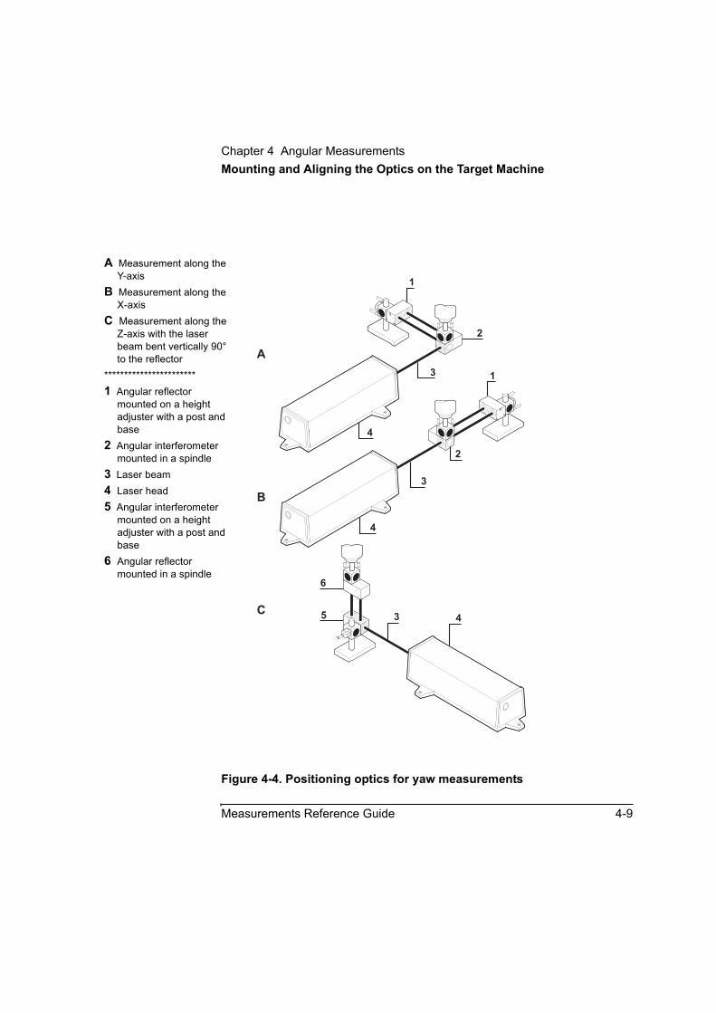
Figure 4-4. Positioning optics for yaw measurements
A Measurement along the Y-axis
B Measurement along the X-axis
C Measurement along the Z-axis with the laser beam bent vertically 90° to the reflector
***********************1 Angular reflector
mounted on a height adjuster with a post and base
2 Angular interferometer mounted in a spindle
3 Laser beam4 Laser head5 Angular interferometer
mounted on a height adjuster with a post and base
6 Angular reflector mounted in a spindle
1
2
6
5
110785A
HEIG
HT ADJUSTER
A
10785A
HE
IGHTADJUSTER
A
43
4
3
4
3
A
B
C
2
Chapter 4 Angular MeasurementsMounting and Aligning the Optics on the Target Machine
4-10 Measurements Reference Guide
5 Assemble the mounting hardware and optic you plan to mount on the table. Follow these steps:
a. Assemble the base, post, and height adjuster (Figure 4-5).
b. Attach either the interferometer or the reflector to this assembly.
• If you plan to mount the interferometer on the table, attach the interferometer to this assembly as shown in Figure 4-5 (pitch measurements) or Figure 4-6 (yaw measurements).
• If you plan to mount the reflector on the table, attach the reflector to this assembly as shown in Figure 4-7 (pitch measurements) or Figure 4-8 (yaw measurements).
6 Mount the optic you assembled in step 5 on the machine’s table top.
Keep the following in mind (see Figures 4-3 and 4-4):
• The side of the interferometer with the two openings must face the reflector.
• One of the single openings on the interferometer must face the laser head.
NOTE If you plan on making a straightness or squareness measurement later, position the height adjuster flush with the top of the post so you can easily change optics.
Chapter 4 Angular MeasurementsMounting and Aligning the Optics on the Target Machine
Measurements Reference Guide 4-11
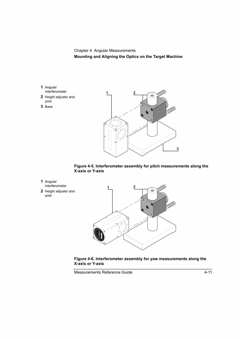
Figure 4-5. Interferometer assembly for pitch measurements along the X-axis or Y-axis
Figure 4-6. Interferometer assembly for yaw measurements along the X-axis or Y-axis
1 Angular interferometer
2 Height adjuster and post
3 Base 10785A
HE
IGHTADJUSTER
A
21
3
1 Angular interferometer
2 Height adjuster and post
21
10770A
A
NGULARINTE
RFEROMETER
1A0101
10785A
HE
IGHTADJUSTER
A
Chapter 4 Angular MeasurementsMounting and Aligning the Optics on the Target Machine
4-12 Measurements Reference Guide
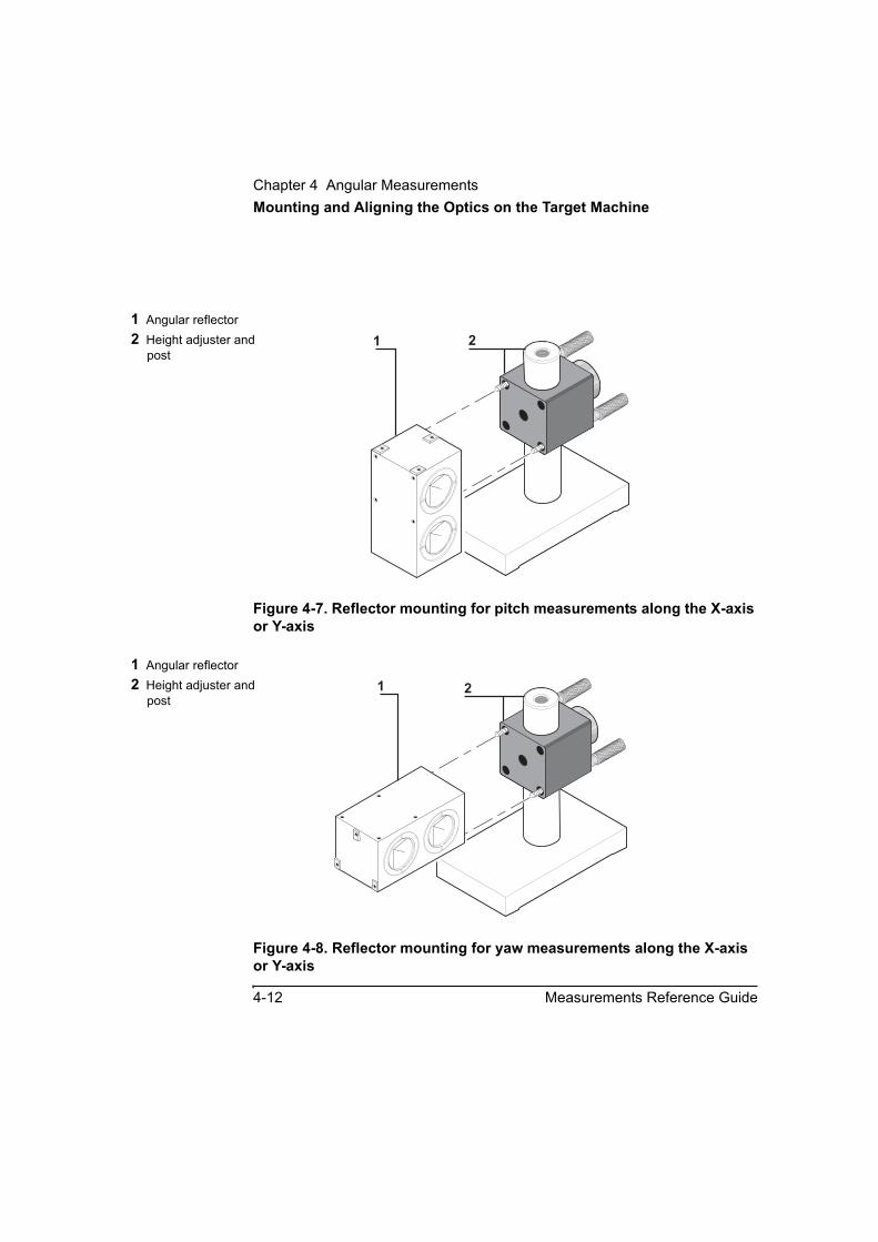
Figure 4-7. Reflector mounting for pitch measurements along the X-axis or Y-axis
Figure 4-8. Reflector mounting for yaw measurements along the X-axis or Y-axis
1 Angular reflector2 Height adjuster and
post
10785A
HE
IGHTADJUSTER
A
1 2
1 Angular reflector2 Height adjuster and
post
10785A
HE
IGHTADJUSTER
A
21

Chapter 4 Angular MeasurementsMounting and Aligning the Optics on the Target Machine
Measurements Reference Guide 4-13
In the following steps, you will fasten a post to the height adjuster on the optic you plan to mount in the machine’s spindle. (You can then insert the post into the spindle and secure it.) You can connect the post to the height adjuster in one of two ways, as explained in the next step.
7 Either insert the post into the optics height adjuster and tighten the knurled knob, or remove the large knurled knob from the height adjuster and screw in the post as shown in Figure 4-9.
The method you choose to mount the optic is up to you.
Figure 4-9. Alternate height adjuster mounting
A Removing the large knurled knob
B Screwing in the post***********************1 Spindle2 Post3 Height adjuster4 Large knurled knob
10785AHEIGHT
ADJU
STER
A
4
3
1
2
3
A B
Chapter 4 Angular MeasurementsMounting and Aligning the Optics on the Target Machine
4-14 Measurements Reference Guide
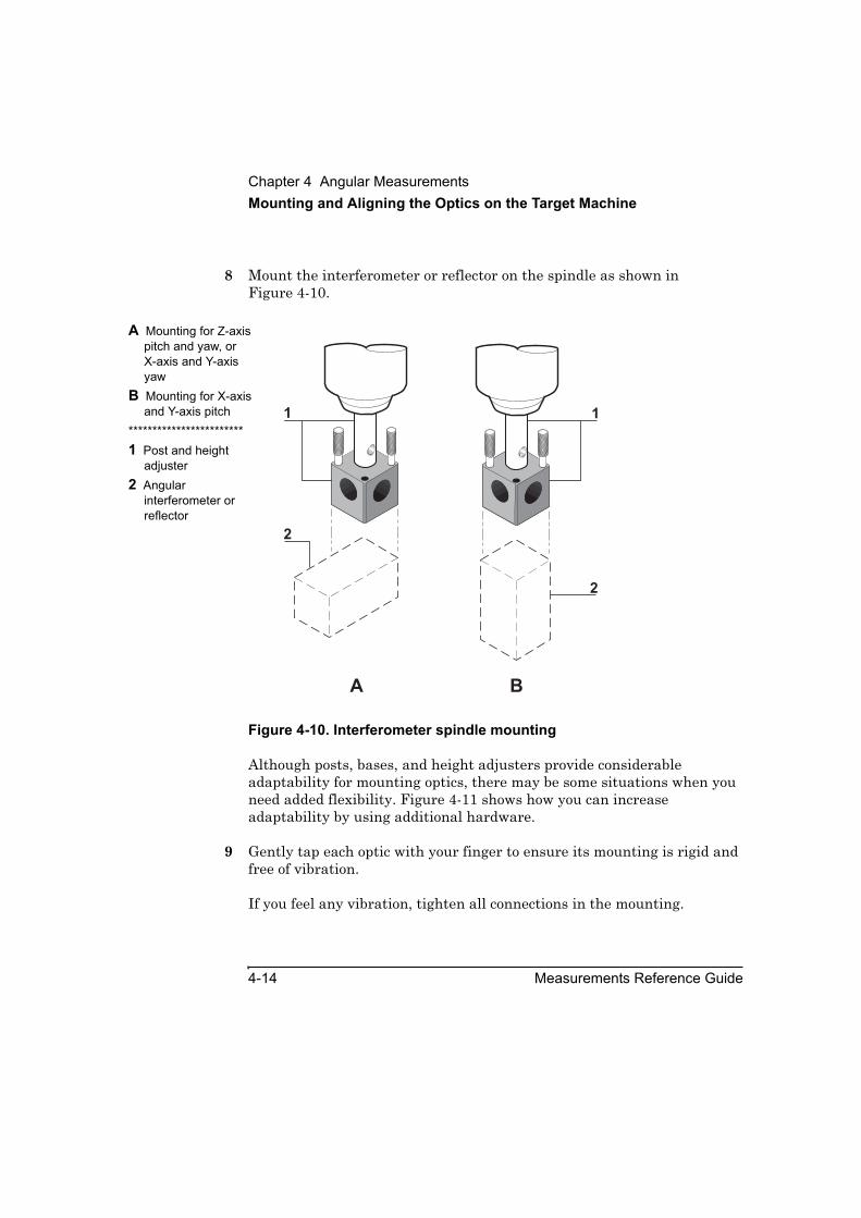
8 Mount the interferometer or reflector on the spindle as shown in Figure 4-10.
Figure 4-10. Interferometer spindle mounting
Although posts, bases, and height adjusters provide considerable adaptability for mounting optics, there may be some situations when you need added flexibility. Figure 4-11 shows how you can increase adaptability by using additional hardware.
9 Gently tap each optic with your finger to ensure its mounting is rigid and free of vibration.
If you feel any vibration, tighten all connections in the mounting.
A Mounting for Z-axis pitch and yaw, or X-axis and Y-axis yaw
B Mounting for X-axis and Y-axis pitch
************************1 Post and height
adjuster2 Angular
interferometer or reflector
2
2
1
BA
1

Chapter 4 Angular MeasurementsMounting and Aligning the Optics on the Target Machine
Measurements Reference Guide 4-15
If you previously made linear measurements using the mounting hardware the angular optics are now on, the optics are already aligned. Since you aligned the laser beam to the machine’s travel path prior to making the linear measurement, you can go directly to “Making the Measurement” later in this chapter.
Figure 4-11. Added mounting flexibility
If you did not previously make linear measurements, you must align the optics. Continue with the next section, “Aligning the optics.”
1 C-clamp2 Base3 Post and height
adjuster4 Interferometer or
retroreflector
10785A
HEIG
HT ADJUSTER
A
HEWLETT
-P
AC
KA
R
10785AHEIGHT
ADJU
STER
A
1 2 3 4
3

Chapter 4 Angular MeasurementsMounting and Aligning the Optics on the Target Machine
4-16 Measurements Reference Guide
Aligning the opticsTo align the optics, follow these steps:
1 Set the laser head’s upper port to the small aperture by turning the upper aperture control (Figure 2-13 in Chapter 2).
2 Rotate the target into position on laser head’s lower port by turning the lower aperture control.
3 Set the laser head’s turret ring to OTHER.
4 Attach a target to the interferometer on the side facing the laser head so the target’s cross hairs are below the target’s hole and the edges of the target line up as evenly as possible with the edge of the interferometer (Figure 4-12).

Chapter 4 Angular MeasurementsMounting and Aligning the Optics on the Target Machine
Measurements Reference Guide 4-17
Figure 4-12. Attaching a target to the interferometer
A Pitch measurementB Yaw measurementC Perpendicular yaw
measurement 10770A
ANGU
LARINT
ERFEROMETER
1 A0 1
0 1
A
B
C
Chapter 4 Angular MeasurementsMounting and Aligning the Optics on the Target Machine
4-18 Measurements Reference Guide
5 Adjust the interferometer or laser head so that:
• the laser beam enters the hole of the target on the interferometer
• the interferometer is as perpendicular as possible to the beam
To adjust the interferometer up or down, loosen the large knob on the height adjuster, move the interferometer up or down, then tighten the knob. You can also move the interferometer left or right or rotate it left or right.
You can adjust the laser head by rotating it, translating it, or both.
6 Secure the interferometer to the target machine, maintaining the laser beam’s position in the center of the interferometer’s target.
To secure the interferometer to a machine table, use a clamp or similar instrument. Observe the following guidelines when securing the interferometer:
• If you are securing the optic to the spindle, lock the spindle in place.
• If you are securing the optic to a surface such as a machine table, make sure the surface is flat so the optic will not rock.
• When using a clamp to secure the optic, try to cover as much of the optic’s base as possible with the clamp so the attachment is secure.
7 Remove the target from the interferometer.
8 Move the reflector as close as possible to the interferometer, and line up the edges of the reflector with the edges of the interferometer.
In the rest of this chapter, the position of the reflector near the interferometer as described above will be referred to as the “start position.”

Chapter 4 Angular MeasurementsAligning the Laser Beam to the Machine’s Travel Path for Long-Range Measurements
Measurements Reference Guide 4-19
9 Adjust the reflector so that:
• its return beam centers on the target covering the laser head’s return port, and
• the reflector is as perpendicular as possible to the beam coming from the interferometer
10 You can adjust the reflector the same way you adjusted the interferometer.
Secure the reflector to the target machine, maintaining the return beam’s position in the center of the laser head’s target.
See the guidelines for securing an optic listed in step 6.
You are now ready to align the laser beam to the laser beam’s travel path.
If your measurement distance is less than 350 mm (14 inches), go directly to “Aligning the Laser Beam to the Machine’s Travel Path for Short-Range Measurements.”
If your measurement distance is greater than 350 mm (14 inches), continue with the next section, “Aligning the Laser Beam to the Machine’s Travel Path for Long-Range Measurements.”
Aligning the Laser Beam to the Machine’s Travel Path for Long-Range MeasurementsFollow the instructions in “Aligning the Laser Beam to the Machine’s Travel Path for Long-Range Measurements” in Chapter 2.
You are now ready to make the measurement. Go directly to “Making the Measurement.”

Chapter 4 Angular MeasurementsAligning the Laser Beam to the Machine’s Travel Path for Short-Range Measurements
4-20 Measurements Reference Guide
Aligning the Laser Beam to the Machine’s Travel Path for Short-Range MeasurementsFollow the instructions in “Aligning the Laser Beam to the Machine’s Travel Path for Short-Range Measurements” in Chapter 2.
You are now ready to make the measurement. Continue with the next section, “Making the Measurement.”
Making the Measurement In this procedure, you make manual measurements as you move the machine’s moveable part. If you are using sensors, make sure they are properly placed and the software is set up correctly. (Refer to the Agilent 5530 Getting Started Guide for complete instructions on using the software and the sensors.)
This section explains how to make measurements using the Record button in the software and the optional remote control unit. See Chapter 1, “Planning Your Measurements,” for a description of other triggering methods.
To make the measurement, follow these steps:
1 Move the moveable optic so it is at its start position.
2 On the Set Up Laser: ANGULAR screen, select Set Up Meas.
The Set Up Measurement: ANGULAR screen is displayed (Figure 4-13).

Chapter 4 Angular Measurements
Making the Measurement
Measurements Reference Guide 4-21
Figure 4-13. Set Up Measurement: ANGULAR screen
3 Complete the fields on the Set Up Measurement: ANGULAR screen.
If necessary, use the online help.
4 Select Collect Data.
The Collect Data: ANGULAR screen is displayed (Figure 4-14).
5 On the Collect Data: ANGULAR screen, select Reset Position.
This tells the system that the current position of the reflector is the “zero” point from which all distances will be measured.
If necessary, use the online help to complete the rest of the fields on this screen.

Chapter 4 Angular Measurements
Making the Measurement
4-22 Measurements Reference Guide
Figure 4-14. Collect Data: ANGULAR screen
6 Move the machine's moveable part to the first measurement point.
7 Select Record.
If you are using the optional remote control unit, press the Record button.
8 Continue moving the machine’s moveable part to each point and recording measurements until the machine has reached the last measurement position.
NOTE If at any point the Reset Laser message flashes, the laser beam path has been broken. Move the moveable optic back to the last point measured, then select Reset Position to reset the system.

Chapter 4 Angular Measurements
Making the Measurement
Measurements Reference Guide 4-23
After the last measurement is recorded, the Analyze Data: ANGULAR screen is displayed (Figure 4-15).
Figure 4-15. Analyze Data: ANGULAR screen
9 On the Analyze Data: ANGULAR screen, select Save Data to create or update a data file with the measurement data.
Refer to the Agilent 5530 Getting Started Guide and online help for more information about using this screen. Otherwise, you are finished making the measurement.
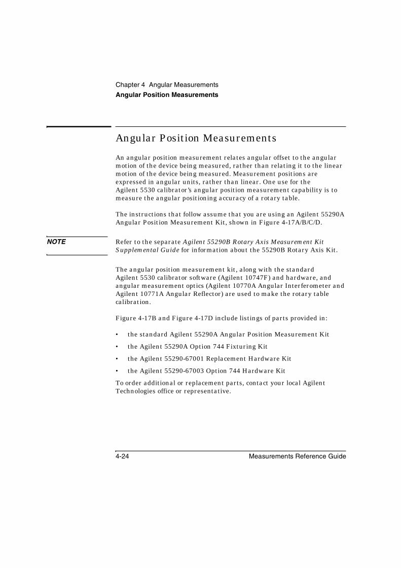
Chapter 4 Angular Measurements
Angular Position Measurements
4-24 Measurements Reference Guide
Angular Position Measurements
An angular position measurement relates angular offset to the angular motion of the device being measured, rather than relating it to the linear motion of the device being measured. Measurement positions are expressed in angular units, rather than linear. One use for the Agilent 5530 calibrator’s angular position measurement capability is to measure the angular positioning accuracy of a rotary table.
The instructions that follow assume that you are using an Agilent 55290A Angular Position Measurement Kit, shown in Figure 4-17A/B/C/D.
NOTE Refer to the separate Agilent 55290B Rotary Axis Measurement Kit Supplemental Guide for information about the 55290B Rotary Axis Kit.
The angular position measurement kit, along with the standard Agilent 5530 calibrator software (Agilent 10747F) and hardware, and angular measurement optics (Agilent 10770A Angular Interferometer and Agilent 10771A Angular Reflector) are used to make the rotary table calibration.
Figure 4-17B and Figure 4-17D include listings of parts provided in:
• the standard Agilent 55290A Angular Position Measurement Kit
• the Agilent 55290A Option 744 Fixturing Kit
• the Agilent 55290-67001 Replacement Hardware Kit
• the Agilent 55290-67003 Option 744 Hardware Kit
To order additional or replacement parts, contact your local Agilent Technologies office or representative.

Chapter 4 Angular MeasurementsAngular Position Measurements
Measurements Reference Guide 4-25
Principles of operationThe system described here measures the angular error of an angular position, not total angular rotation. Basic operation during an angular position measurement is simple and straightforward, and is diagrammed in Figure 4-16A and Figure 4-16B.
1. The precision index table has a Hirth coupling consisting of 360 precision-ground teeth. Its position resolution is one degree, within a ± 0.5 arc-second tolerance. The top of the precision index table, which carries the fixture holding the “moveable” optic, is disengaged from its base.
2. The machine part to be calibrated is rotated, turning the precision index table’s base with it. The table’s top, along with its “moveable” measurement optic is kept from turning by the friction clutch in the fixture.
3. The precision index table’s top is re-engaged with its base, and the fixture’s clutch is disengaged, allowing best engagement of the two parts of the table. The error measured is the combined error of the table under test and the precision index table.
4. The Agilent 5530 calibrator is instructed to record a measurement.
These four steps are repeated until all required data has been collected.

Chapter 4 Angular MeasurementsAngular Position Measurements
4-26 Measurements Reference Guide
Figure 4-16A. Angular position measurements—principles (Part 1 of 2)
0 10 20
350
30
40
50
60
70
8090
100
110
340
330
3200 10 20
350
30
40
50
60
70
8090
100
110
340
330
320
3
Y
Z X
1
Y
Z X
0 10 20
350
30
40
50
60
70
8090
100
110
340
330
320
2
Y
Z X
1a
1b
2a
2b
3a
3b
1 Table “neutral” position 2 Table “disengaged” position 3 Table base rotated
1a No force on clutchFor the machine control program shown in Figure 4-18, the clutch is depressed 1 mm from this position. This motion ensures appropriate engagement force between the table’s top and base.
2a Lift top 3 mm to allow base to rotate. First mm lift returns to “neutral” position and re-engages the clutch; remaining 2 mm provides clearance between table’s top and base, to allow base to rotate. Set the machine’s reference point (relative zero) for this axis after you have performed this lift.
3a Table top has been disengaged, as described in 2a.
1b Table top engaged with base 2b Top lifted to allow base to rotate, as described above.
3b Machine part being calibrated is rotated, turning the table’s base with it.

Chapter 4 Angular MeasurementsAngular Position Measurements
Measurements Reference Guide 4-27
Figure 4-16B. Angular position measurements—principles (Part 2 of 2)
5
4 Table “engaged” position 5 Instruct Agilent 5530 calibrator to collect data.
4a After base has rotated, provide 3.0 mm closing movement to provide sufficient engagement force between top and base.Allow enough dwell time for measurement data collection before beginning next lift-rotate-lower cycle.For remaining measurements, cycle controlling axis between this position and relative zero position.
For remaining measurements, repeat step 2 through this step until all data has been collected.
4b Table top engaged with base
0 10 20
350
30
40
50
60
70
8090
100
110
340
330
320
4
Y
Z X
4a
4b

Chapter 4 Angular MeasurementsAngular Position Measurements
4-28 Measurements Reference Guide
Figure 4-17A. Agilent 55290A or 55290B Angular Position Measurements Kit—(Part 1 of 4)
10 20 30
0
40 50
60
70
80
90100
110
120350
340
330
8
1
2
3
4
5
14
15
16
11
10
12 13
7 96
1718
7
2a
3a3b
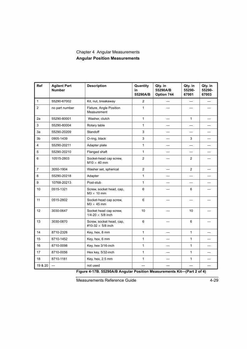
Chapter 4 Angular MeasurementsAngular Position Measurements
Measurements Reference Guide 4-29
Figure 4-17B. 55290A/B Angular Position Measurements Kit—(Part 2 of 4)
Ref Agilent Part Number
Description Quantity in 55290A/B
Qty. in 55290A/B Option 744
Qty. in 55290-67001
Qty. in 55290-67003
1 55290-67002 Kit, nut, breakaway 2 — — —
2 no part number Fixture, Angle Position Measurement
1 — — —
2a 55290-80001 Washer, clutch 1 — 1 —
3 55290-80004 Rotary table 1 — — —
3a 55290-20209 Standoff 3 — — —
3b 0905-1439 O-ring, black 3 — 3 —
4 55290-20211 Adapter plate 1 — — —
5 55290-20210 Flanged shaft 1 — — —
6 10515-2803 Socket-head cap screw, M10 × 40 mm
2 — 2 —
7 3050-1904 Washer set, spherical 2 — 2 —
8 55290-20218 Adapter 1 — — —
9 10768-20213 Post-stub 1 — — —
10 0515-1321 Screw, socket head, cap, M3 × 10 mm
6 — 6 —
11 0515-2802 Socket-head cap screw, M3 × 45 mm
6 — — —
12 3030-0647 Socket head cap screw,1/4-20 × 5/8 inch
10 — 10 —
13 3030-0870 Screw, socket head, cap, #10-32 × 5/8 inch
6 — 6 —
14 8710-2326 Key, hex, 8 mm 1 — 1 —
15 8710-1452 Key, hex, 6 mm 1 — 1 —
16 8710-0098 Key, hex 3/16-inch 1 — 1 —
17 8710-0056 Hex key, 5/32-inch 1 — 1 —
18 8710-1181 Key, hex, 2.5 mm 1 — 1 —
19 & 20 — not used — — — —

Chapter 4 Angular MeasurementsAngular Position Measurements
4-30 Measurements Reference Guide
Figure 4-17C. 55290A/B Angular Position Measurements Kit (option 744)—(Part 3 of 4)
25
21
22
23
22
24
26
27
10785A
HEIG
HT ADJUSTER
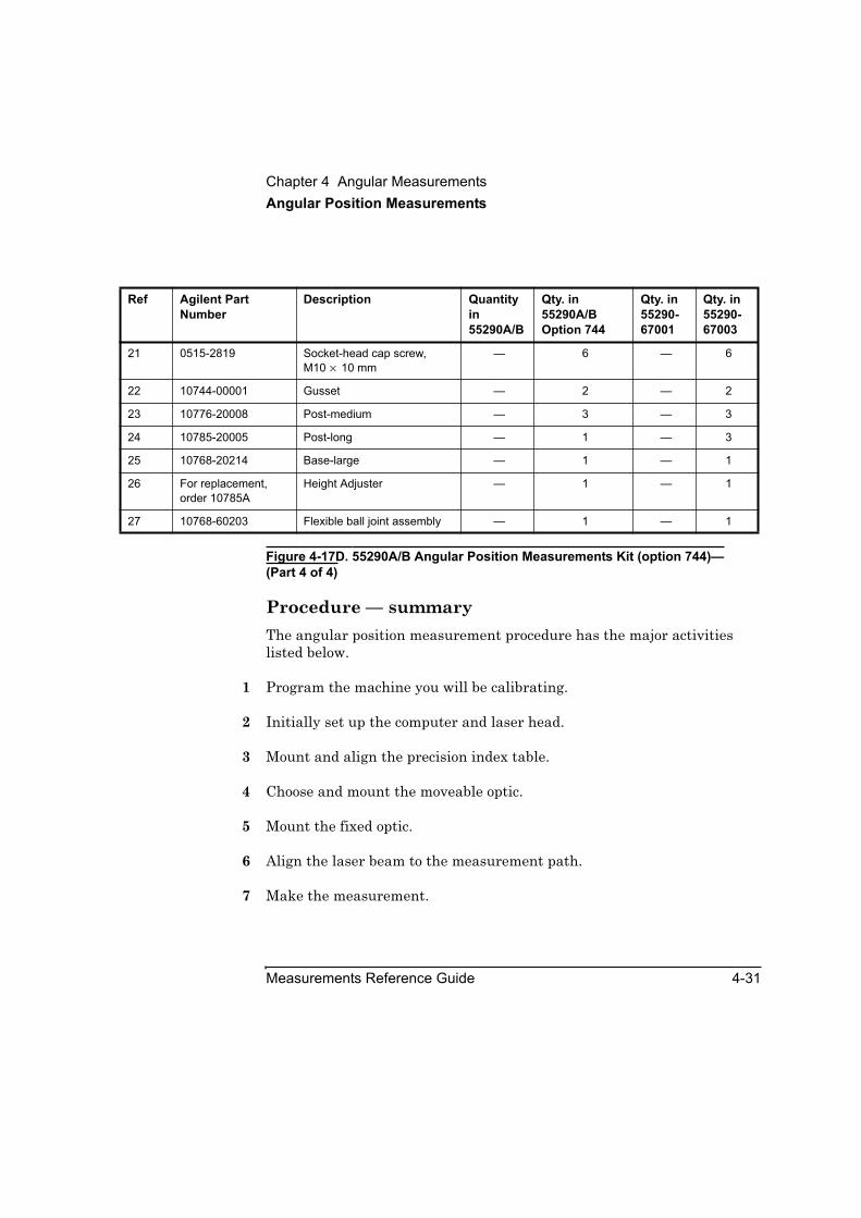
Chapter 4 Angular MeasurementsAngular Position Measurements
Measurements Reference Guide 4-31
Figure 4-17D. 55290A/B Angular Position Measurements Kit (option 744)—(Part 4 of 4)
Procedure — summaryThe angular position measurement procedure has the major activities listed below.
1 Program the machine you will be calibrating.
2 Initially set up the computer and laser head.
3 Mount and align the precision index table.
4 Choose and mount the moveable optic.
5 Mount the fixed optic.
6 Align the laser beam to the measurement path.
7 Make the measurement.
Ref Agilent Part Number
Description Quantity in 55290A/B
Qty. in 55290A/B Option 744
Qty. in 55290-67001
Qty. in 55290-67003
21 0515-2819 Socket-head cap screw, M10 × 10 mm
— 6 — 6
22 10744-00001 Gusset — 2 — 2
23 10776-20008 Post-medium — 3 — 3
24 10785-20005 Post-long — 1 — 3
25 10768-20214 Base-large — 1 — 1
26 For replacement, order 10785A
Height Adjuster — 1 — 1
27 10768-60203 Flexible ball joint assembly — 1 — 1

Chapter 4 Angular MeasurementsAngular Position Measurements
4-32 Measurements Reference Guide
Programming the machine to be calibratedBecause of the variety of controllers, it is not possible to present specific instructions for any particular one here. Apply the information presented here to your measurement situation.
Before you install hardware on your machine, you should program the machine to perform the basic movements it will be doing during the measurement. A description of the measurement steps is provided in the previous section “Procedure — summary”.
The example program in Figure 4-18 assumes that the machine’s relative zero was set with the machine holding the measurement fixture and the top of the precision index table in the position that allows the base of the table to rotate independently from the top. This position is 2 mm above the “neutral” position. Refer also to Figure 4-16A/B. The example program in Figure 4-18:
1. Starts from relative zero position set for your measurement, with the precision index table’s top lifted to allow clearance for its base to rotate independently.
2. Rotates the table’s base the number of degrees you specify.
3. Engages the table’s top and base, by lowering the top 3 mm. Feed rate and clamping force during engagement are important.
The feed rate during engagement is specified. Too slow a feed rate may result in poor engagement repeatability. Too fast a feed rate may damage measurement hardware or cause vibrations in the setup.
The correct clamping force is provided when the clutch is forced 1 mm below its “neutral” position.
4. Dwells at the engaged position for the time specified, to allow the Agilent 5530 calibrator to collect data.
5. Lifts the top of the precision index table 3 mm, to completely disengage it from the table’s base.

Chapter 4 Angular MeasurementsAngular Position Measurements
Measurements Reference Guide 4-33
NOTE The example program, in Figure 4-18, does not include setting the relative zero position, which you must do after you finish installing the measurement hardware.
The measurement fixture clutch is designed to apply the desired clamping force when the clutch control shaft has been pressed 1 mm in (down) from its “neutral” position.
The precision index table requires a lift (up) of 2 mm from the measurement fixture clutch’s “neutral” position. The program example assumes that you have set the Z-axis reference with that lift performed; that is, the Z-axis reference position is with the top of the precision table 2 mm above its neutral position.
The example program in Figure 4-18 does not automatically cycle.
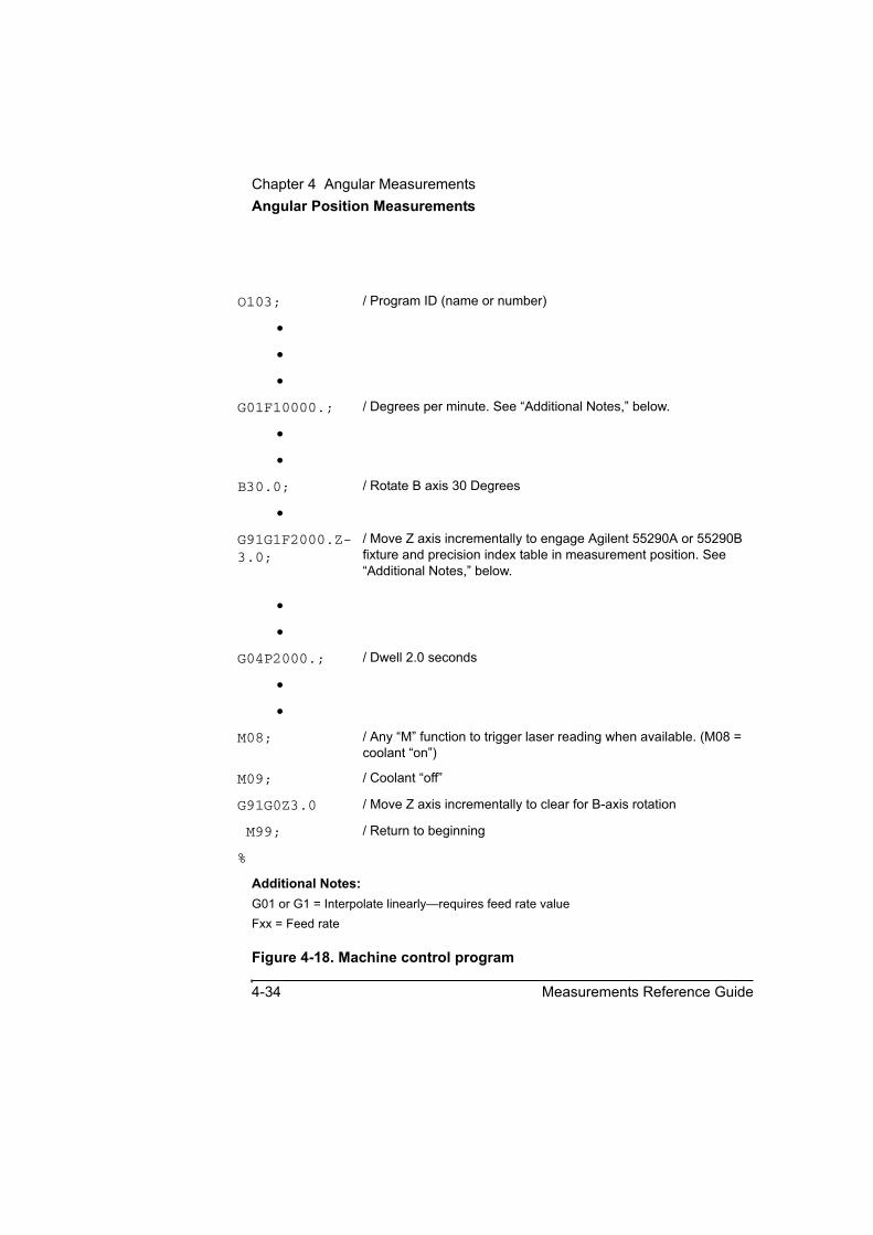
Chapter 4 Angular MeasurementsAngular Position Measurements
4-34 Measurements Reference Guide
Additional Notes:G01 or G1 = Interpolate linearly—requires feed rate valueFxx = Feed rate
Figure 4-18. Machine control program
O103; / Program ID (name or number)
•
•
•
G01F10000.; / Degrees per minute. See “Additional Notes,” below.
•
•
B30.0; / Rotate B axis 30 Degrees
•
G91G1F2000.Z-3.0;
/ Move Z axis incrementally to engage Agilent 55290A or 55290B fixture and precision index table in measurement position. See “Additional Notes,” below.
•
•
G04P2000.; / Dwell 2.0 seconds
•
•
M08; / Any “M” function to trigger laser reading when available. (M08 = coolant “on”)
M09; / Coolant “off”
G91G0Z3.0 / Move Z axis incrementally to clear for B-axis rotation
M99; / Return to beginning
%

Chapter 4 Angular MeasurementsAngular Position Measurements
Measurements Reference Guide 4-35
Initial setup of computer and laser headIf you have not already done so, perform the following setup procedures before using the rest of the instructions in this procedure. Refer to the Agilent 5530 Getting Started Guide for complete instructions on performing these steps.
1 Mount the laser head on the tripod and place the tripod near the target machine.
2 Connect the E1735A USB Axis Module and the E1736A USB Sensor Hub to the PC. Connect the laser head and remote control unit to the axis module. Connect the sensors to the sensor hub.
The appropriate connectors are either on the rear or the side of the PC.
3 Plug in and turn on all equipment.
4 Start the metrology software.
The Metrology Main Menu is displayed.
On the Metrology Main Menu, select Angular.
5 The Set Up Laser: ANGULAR screen is displayed.
Alternatively, you can open an existing angular measurement setup file from your database by selecting Recall Data on the Main Menu.
6 Complete the fields on the Set Up Laser: ANGULAR screen.
7 In the Measurement Axis box, select 55290A. The display changes to that shown in Figure 4-19. (Instructions for Pitch or Yaw measurements are given in “Setting Up for a Pitch or Yaw Measurement” earlier in this chapter.)
If necessary, use the Agilent 5530 calibrator’s online help.

Chapter 4 Angular MeasurementsAngular Position Measurements
4-36 Measurements Reference Guide
To obtain the greatest accuracy possible, you must account for environmental factors such as ambient temperature and humidity. If you are not using sensors, follow steps 7 through 9 in “Setting Up for the Measurement” in Chapter 2. If you are using sensors, follow the instructions in “Placing and Using the Sensors” in Chapter 2.
NOTE Changes in the interferometer’s or the reflector’s temperature willaffect the accuracy of your measurements. To minimize this problem,(1) avoid excessive handling of the optics, and (2) keep the optics away from sources of heat and cold, such as air vents.
You are now ready to mount and align the precision index table and optics on the target machine.
Figure 4-19. Set Up Laser: ANGULAR screen

Chapter 4 Angular MeasurementsAngular Position Measurements
Measurements Reference Guide 4-37
Mounting and aligning the precision index table on the target machineThis section explains how to correctly mount and align the precision index table on the target machine before making an angular position (Angle) measurement.
Mounting and aligning on a rotary table
NOTE We expect that most installations will require use of the adapter plate. If your rotary table already has mounting holes that allow proper centering of the precision index table, you do not need to use the adapter plate.
1 Fasten the adapter plate to your machine’s rotary table. (See Figure 4-20.)
2 Center the adapter plate on the rotary table’s rotation axis.
3 Remove the locking ring at the bottom of the precision index table. (See Figure 4-22.)
4 Separate the precision index table’s top and base and inspect their Hirth coupling teeth for cleanliness. If necessary, clean the teeth. A procedure for cleaning the Hirth coupling teeth is given in the “Maintenance” section of this chapter.
5 Rejoin the precision index table’s top and base and use the locking loops to hold them together. (See Figure 4-22.)
6 Fasten the precision index table to the adapter plate. (See Figure 4-20.)
7 Center the precision index table within 25.4 μm (0.001 inch) on your machine’s rotary table rotation axis.
8 Go to “Choosing the moveable optic” below.

Chapter 4 Angular MeasurementsAngular Position Measurements
4-38 Measurements Reference Guide
Figure 4-20. Mounting on a rotary table
1 Socket-head cap screw, 1/4 - 20 × 5/8-inch
2 Precision index table3 Adapter plate4 Rotary table to be
calibrated5 Locking loop(s)
10 20 30
0
40 50
60
70
80
90100
110
120350
340
3302
1
3
4
5
Chapter 4 Angular MeasurementsAngular Position Measurements
Measurements Reference Guide 4-39
Mounting and aligning on a machining center1 Fasten the adapter plate to the flanged shaft. (See Figure 4-21.)
2 Insert the flanged shaft into your machine’s work piece spindle.
3 Use the locking loops to hold the precision index table top and base together. (SeeFigure 4-22.)
4 Remove the locking ring at the bottom of the precision index table. (See Figure 4-22.)
5 Fasten the precision index table to the adapter plate. (See Figure 4-21.)
6 Center the precision index table within 25.4 μm (0.001 inch) on your machine’s work piece spindle rotation axis.
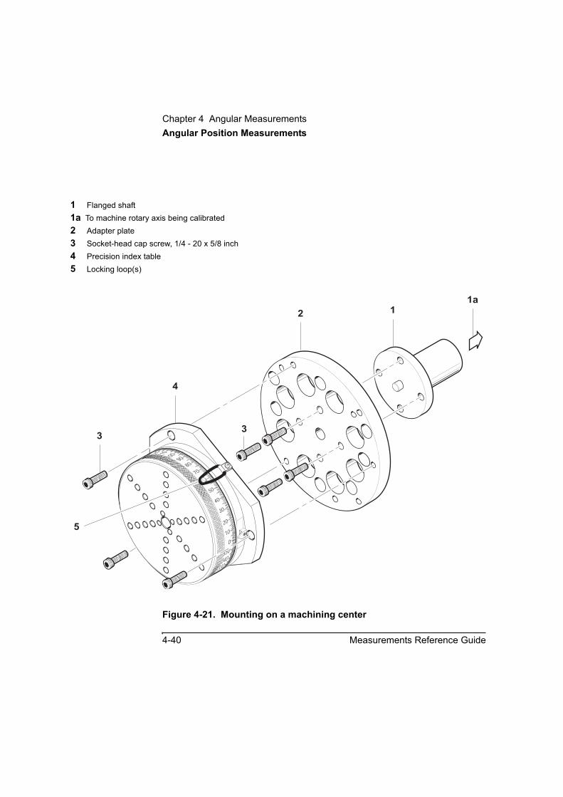
Chapter 4 Angular MeasurementsAngular Position Measurements
4-40 Measurements Reference Guide
Figure 4-21. Mounting on a machining center
1 Flanged shaft1a To machine rotary axis being calibrated2 Adapter plate3 Socket-head cap screw, 1/4 - 20 x 5/8 inch4 Precision index table5 Locking loop(s)
10
20
30
0
40
50
60
7080
90100110120
350
340330
12
4
33
1a
5
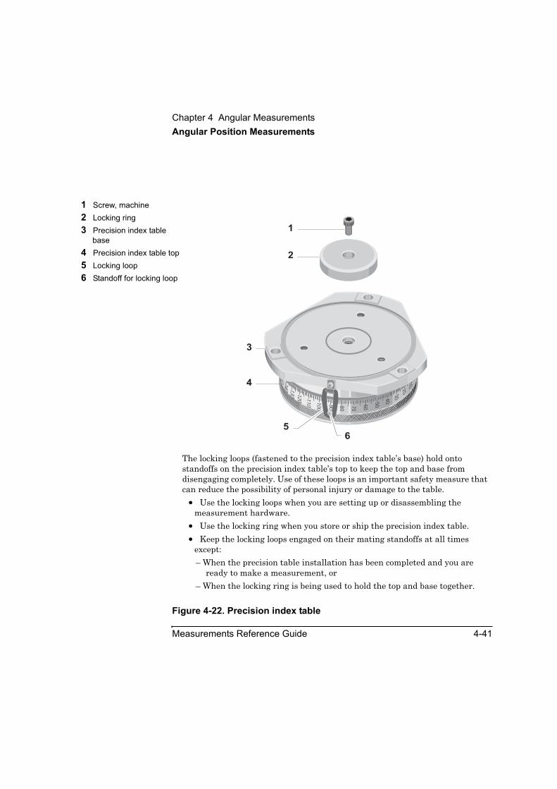
Chapter 4 Angular MeasurementsAngular Position Measurements
Measurements Reference Guide 4-41
Figure 4-22. Precision index table
1 Screw, machine2 Locking ring3 Precision index table
base4 Precision index table top5 Locking loop6 Standoff for locking loop
The locking loops (fastened to the precision index table’s base) hold onto standoffs on the precision index table’s top to keep the top and base from disengaging completely. Use of these loops is an important safety measure that can reduce the possibility of personal injury or damage to the table. • Use the locking loops when you are setting up or disassembling the
measurement hardware. • Use the locking ring when you store or ship the precision index table. • Keep the locking loops engaged on their mating standoffs at all times
except:– When the precision table installation has been completed and you are
ready to make a measurement, or– When the locking ring is being used to hold the top and base together.
110 100
90
120
80 70
60
50
40
3020
100
130
140
150
1
2
3
4
56
Chapter 4 Angular MeasurementsAngular Position Measurements
4-42 Measurements Reference Guide
Choosing the moveable opticUse the Agilent 10771A Angular reflector as the moveable optic whenever possible. This setup can easily accommodate the 2 mm lift required for clearance between the top and base of the precision index table.
A setup with the Angular reflector as the moveable optic can handle lifts greater than 2 mm. However, since moving (translating) the reflector translates the return beam at the Laser Head by twice the amount of the lift, you may not be able to maintain adequate return beam strength throughout your measurement.
If the lift required by your measurement causes so much return beam loss that you lose the measurement signal, you can try using the Agilent 10770A Angular interferometer as the moveable optic, with the Laser Head set for STRAIGHTness, and the beam pointed directly into the reflector’s “corner” so the return beam is along the same path. (See Figure 4-30A/B.) Be aware, however, that the interferometer’s specification for this use is not as good as that of the reflector, and you will have to perform an additional calibration procedure.
When the Angular interferometer is the moveable optic, the return beam is not translated when the optic is moved. The primary limit to lift distance in this situation is the difference in diameter between the laser beam (6 mm) and the diameter of the interferometer’s clear aperture (about 20.83 mm). Environmental conditions and alignment can also affect maximum lift with this configuration.
Mounting the moveable opticFigure 4-23 shows two different arrangements that can be used for mounting the moveable optic in the angular position measurements fixture. Screws for both mounting arrangements are included in the Agilent 55290A or 55290B kit.
The top-screw mounting arrangement is recommended for use with newer versions of the retroreflector, whose housings have the required hole configuration.

Chapter 4 Angular MeasurementsAngular Position Measurements
Measurements Reference Guide 4-43
The bottom-screw mounting arrangement is required for any of the measurement optic whose housing does not have the hole configuration required for top-screw mounting.
Figure 4-23. Mounting the moveable optic in the measurement fixture
1 Cap-head machine screw, M3 x 45 mm2 Fixture top 3 Moveable optic4 Fixture base5 Cap-head machine screw, M3 x 10 mm
* **Mounting methods—use the appropriate one* top-screw mounting—newer optics only** bottom-screw mounting—older or newer optics
1
2
3
5
3
4

Chapter 4 Angular MeasurementsAngular Position Measurements
4-44 Measurements Reference Guide
After mounting the moveable optic in the angular position measurements fixture, mount the fixture on the precision index table.
Figure 4-24. Mounting the measurement fixture on the precision index table
1 Socket-head cap screw, 10-32 x 5/8-inch
2 Measurement fixture3 Precision index table top
0 10 20
350
30
40
50
60
70
8090
100
110
340
330
320
2
1
3
Chapter 4 Angular MeasurementsAngular Position Measurements
Measurements Reference Guide 4-45
Creating the control linkThe main goal of the procedures below is to connect the angular position measurement fixture to the machine’s spindle or other lifting mechanism while ensuring there is no outside force on the clutch control shaft in any direction. The fixturing aids listed in Figure 4-17A/B/C/D are provided to help you do this.
In long linkages, the Agilent posts may be too flexible, so custom fixturing may be needed.
Taking care of the measurement fixture’s clutchSee Figure 4-25.
The angular position measurements fixture’s friction clutch prevents unwanted movement of the precision index table’s top when it is disengaged from the table’s base.
NOTE The clutch must never carry any of the weight of the linkage after final assembly and tightening of the linkage.
To prolong clutch life, do not rotate the clutch control shaft with respect to the rest of the fixture when the clutch is engaged. The clutch is normally engaged. To disengage it, rock the control shaft or press it toward the fixture’s base.
If the clutch has not been used for more than about two days, it may be difficult to disengage it. Before using the clutch, you should manually disengage it. In this case, you can rock the clutch by manually tilting the clutch control shaft with respect to the rest of the angular measurement fixture.
To keep the clutch from being rocked or disengaged during installation, whether due to the weight of the linkage assembly or due to tightening, hand-tighten the clutch breakaway nut onto the clutch shaft.

Chapter 4 Angular MeasurementsAngular Position Measurements
4-46 Measurements Reference Guide
CAUTION Never use an ordinary nut in place of the clutch breakaway nut. The ordinary nut is not designed to provide the breakaway-under-load protection provided by the Agilent-provided nut.
After you have assembled and tightened the linkage, unscrew the clutch breakaway nut and position it about 5 mm (1/4-inch) up the shaft, so it does not interfere with operation of the clutch.
Spherical washer sets are particularly useful in right-angle situations, when used with the Agilent-provided adapter, or on complex linkages where out-of-squareness can be a problem.
Figure 4-25. Clutch
1 Clutch control shaft2 Clutch breakaway nut3 Clutch washer4 Top of measurement fixture
* ** ***
“Neutral” positionSide force rocking (jogging) clutchBreakaway nut tightened to lock clutch in its engaged position.This is done for setups only. Do not lock the clutch during measurements.
2
3
1
4
* ** ***

Chapter 4 Angular MeasurementsAngular Position Measurements
Measurements Reference Guide 4-47
For parallel spindle and table axesSee Figure 4-26.
1 Perform all appropriate steps of the setup, mounting, and aligning procedures above.
NOTE The clutch breakaway nut is not required for a setup having both the table axis and the spindle axis vertical. However, you may use it in this situation with no problem. If you choose not to use the clutch breakaway nut, modify this procedure accordingly. You should use the clutch breakaway nut in any setup where the table axis is horizontal.
2 Place the clutch breakaway nut on the clutch control shaft, if it is not already there, but do not tighten it.
3 Screw the stub post onto the small threaded portion at the end of the clutch control shaft. Without allowing the shaft to rotate with respect to the rest of the fixture, tighten the stub post onto the shaft.
4 If necessary, jog the clutch control shaft to position it in the center of its hole in the angular position measurements fixture.
5 Tighten the clutch breakaway nut on the clutch control shaft against the top of the angular position measurements fixture. This locks the clutch in its engaged position, and prevents any load from the linkage hardware from affecting the shaft’s position.
6 Insert a post in the spindle, with its externally-threaded end extended.
7 Position the machine parts as necessary to center the stub post’s mating hole at the end of the post in the spindle.
8 If necessary, loosen the post in the spindle so it can be brought into contact with the stub post on the clutch control shaft.

Chapter 4 Angular MeasurementsAngular Position Measurements
4-48 Measurements Reference Guide
9 Without allowing the clutch control shaft to turn, screw the end of the post into the end of the stub post on the shaft. Without allowing the clutch control shaft to turn, tighten the post onto the stub post.
10 Tighten the post in the spindle.
11 Loosen the clutch breakaway nut and run it about 5 mm (1/4-inch) along the clutch control shaft.
12 Disengage the locking loops that have been holding the top and bottom of the precision index table together.
13 Proceed to the “Mounting the fixed optic” instructions below.

Chapter 4 Angular MeasurementsAngular Position Measurements
Measurements Reference Guide 4-49
Figure 4-26. Control linkage for parallel axes
Ref Description Procedure step number
1 Spindle 6 7 8 9 10
2 Post 6 7 8 9 10
3 Post-stub 3 7 8 9
4 Clutch breakaway nut 2 5 11
5 Clutch control shaft 2 3 4 5 9 11
6 Fixture
7 Precision index table
8 Adapter plate
9 Locking loop(s) 12
7
8
6
10 20 30
0
40 50
60
70
80
90100
110
120350
340
330
1
2
3
4
5
9

Chapter 4 Angular MeasurementsAngular Position Measurements
4-50 Measurements Reference Guide
For right-angle spindle and table axesSee Figure 4-27 or Figure 4-28.
This case is similar to the parallel-axes case above, except in how the clutch control shaft is connected to the machine’s spindle or other part that will control it.
1 Perform all appropriate steps of the setup, mounting, and aligning procedures above.
2 Place the clutch breakaway nut on the clutch control shaft, if it is not already there, but do not tighten it.
3 Place the adapter on the clutch control shaft, if it is not already there. Use an open-end wrench to keep the shaft from turning while you use a second wrench to tighten the adapter onto the shaft.
4 If necessary, jog the clutch control shaft to position it in the center of its hole in the angular position measurements fixture.
5 Insert a post in the spindle, with its externally-threaded end extended.
6 Add a stub post to the post in the spindle. Using a wrench or similar tool through the hole in each post, tighten the posts together.
7 If necessary, loosen the post assembly in the spindle so its end can touch the adapter on the clutch control shaft.
8 Rotate the adapter (and clutch control shaft) so the adapter’s mating face is parallel with the end of the post assembly in the spindle and the clearance hole lines up correctly. If more than a few degrees of turning is necessary, jog the control shaft as you turn it, to reduce clutch engagement. Turning the shaft with the clutch engaged increases wear on the clutch, shortening its useful life.
9 Position the machine as necessary to center the adapter’s clearance hole on the end of the post assembly in the spindle.

Chapter 4 Angular MeasurementsAngular Position Measurements
Measurements Reference Guide 4-51
10 Back the post assembly away from the adapter, so it does not exert any force on the clutch control shaft.
11 Tighten the clutch breakaway nut on the clutch control shaft against the top of the angular position measurements fixture.
This locks the clutch in its engaged position, and prevents any load from the linkage hardware from affecting the shaft’s position.
12 Fasten the adapter to the stub post at the end of the post assembly, using the spherical washers and bolt provided.
13 Tighten the post assembly in the spindle.
14 Loosen the clutch breakaway nut and run it about 5 mm (1/4-inch) along the clutch control shaft.
15 Disengage the locking loops that have been holding the top and bottom of the precision index table together.
16 Proceed to the “Mounting the fixed optic” instructions below.
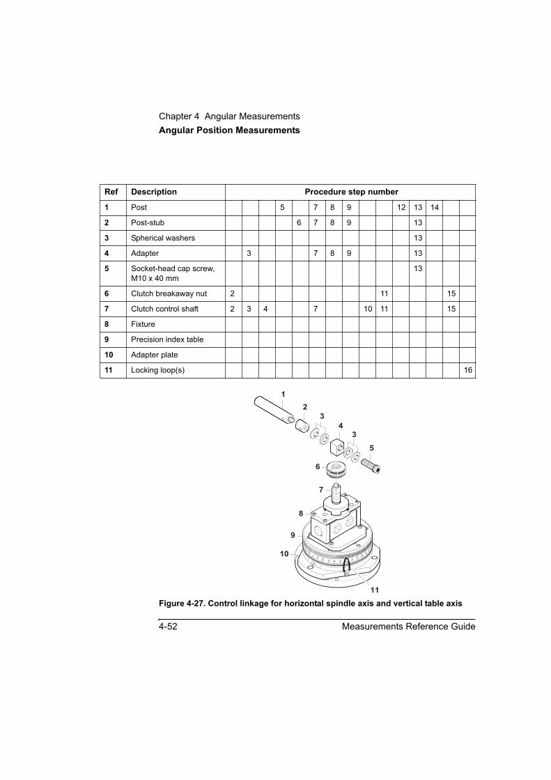
Chapter 4 Angular MeasurementsAngular Position Measurements
4-52 Measurements Reference Guide
Figure 4-27. Control linkage for horizontal spindle axis and vertical table axis
Ref Description Procedure step number
1 Post 5 7 8 9 12 13 14
2 Post-stub 6 7 8 9 13
3 Spherical washers 13
4 Adapter 3 7 8 9 13
5 Socket-head cap screw, M10 x 40 mm
13
6 Clutch breakaway nut 2 11 15
7 Clutch control shaft 2 3 4 7 10 11 15
8 Fixture
9 Precision index table
10 Adapter plate
11 Locking loop(s) 16
1
10 20 30
0
40 50
60
70
80
90100
110
120350
340
330
2
4
3
5
6
7
8
9
10
3
11

Chapter 4 Angular MeasurementsAngular Position Measurements
Measurements Reference Guide 4-53
Figure 4-28. Control linkage for vertical spindle axis and horizontal table axis
Ref Description Procedure step number
1 Post 6 8 9 10 11 12 14 15
2 Post-stub 7 8 9 10 11 12 14
3 Spherical washers 14
4 Adapter 4 8 9 10 11 12 14
5 Socket-head cap screw, M10 x 40 mm
14
6 Clutch breakaway nut 3 13 16
7 Clutch control shaft 3 5 8 13
8 Fixture, with optic installed 2
9 Precision index table 2
10 Adapter plate
11 Locking loop(s) 17
1
2
4
5
6
10
20
30
0
40
50
60
7080
90100110120
350
340330
78
910
3
3
11
Chapter 4 Angular MeasurementsAngular Position Measurements
4-54 Measurements Reference Guide
Mounting the fixed optic1 Create the supporting arrangement for the fixed optic.
For the best measurement accuracy, this arrangement must minimize any possible movement of the fixed optic. A multi-post arrangement (see Figure 4-29) will usually provide a much stiffer support than a single post.
2 Attach the fixed optic to its support.
3 Place the fixed optic in its position in the laser path, as close to the moveable optic as possible.
CAUTION Be sure to position the fixed optic so it will not be hit by any moving part. Be sure to provide enough clearance between the fixed optic and the angular position measurement fixture’s base.
NOTE This procedure was presented here for the majority of expected setups, where the angular reflector is the moveable optic and the angular interferometer is the fixed optic. If the angular reflector is the fixed optic, perform the optics alignment procedure above after you install it.
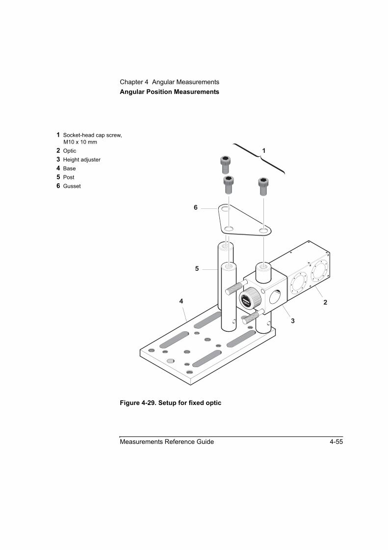
Chapter 4 Angular MeasurementsAngular Position Measurements
Measurements Reference Guide 4-55
Figure 4-29. Setup for fixed optic
1 Socket-head cap screw, M10 x 10 mm
2 Optic3 Height adjuster4 Base5 Post6 Gusset
1
6
5
4 2
3
10785
A HEIGHTAD
JUSTER
Chapter 4 Angular MeasurementsAngular Position Measurements
4-56 Measurements Reference Guide
Aligning the laser beam
NOTE This procedure is presented here for the majority of expected setups, where the angular reflector is the moveable optic and the angular interferometer is the fixed optic. If the angular reflector is the fixed optic, perform this procedure after you install it.
NOTE This procedure assumes setups as shown in Figure 4-30A/B.

Chapter 4 Angular MeasurementsAngular Position Measurements
Measurements Reference Guide 4-57
Figure 4-30A. Typical setups for vertical and horizontal table axes (Part 1 of 2)
* Retroreflector as moving optic
** Interferometer as moving optic
*1 Laser head2 Angular interferometer2a Laser beam(s) at
interferometer3 Angular reflector3a Laser beam(s) at reflector
**
1
1 2
2
3
3
STRAIGHT
OTHER
STRAIGHT
OTHER
2a 3a
2a 3a
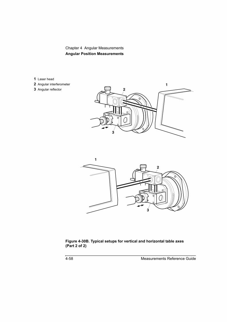
Chapter 4 Angular MeasurementsAngular Position Measurements
4-58 Measurements Reference Guide
Figure 4-30B. Typical setups for vertical and horizontal table axes (Part 2 of 2)
1 Laser head2 Angular interferometer3 Angular reflector 2
3
1
3a
2
1
3
3a

Chapter 4 Angular MeasurementsAngular Position Measurements
Measurements Reference Guide 4-59
To align the laser beam, follow these steps:
1 Orient the angular reflector as you want it to be for your measurement.
2 Mount the interferometer in the beam path, so the beam passes through it to the reflector. No other alignment is needed at this time.
3 Set the laser head’s upper port to the small aperture by turning the upper aperture control (see Figure 2–13).
4 Rotate the target into position on laser head’s lower port by turning the lower aperture control.
5 Set the laser head’s turret ring to OTHER.
6 Position and align the laser head so its beam enters one of the reflector’s ports and is perpendicular to the port’s surface.
7 Place a gage block over the port so it can reflect the laser beam back to the laser head.
8 Rotate the laser head so the beam from the gage block reflects back to its upper (output) port.
9 Remove the gage block from the angular reflector.
10 Translate the laser head so the return beam centers on the target at its lower (return) port.
11 Secure the reflector to the target machine, maintaining the return beam’s position in the center of the laser head’s target.
12 You can adjust the interferometer the same way you adjusted the angular reflector.
You are now ready to align the laser beam to the machine’s travel path.
If your measurement distance is less than 350 mm (14 inches), go directly to “Aligning the Laser Beam to the Machine’s Travel Path for Short-Range Measurements,” in Chapter 2.
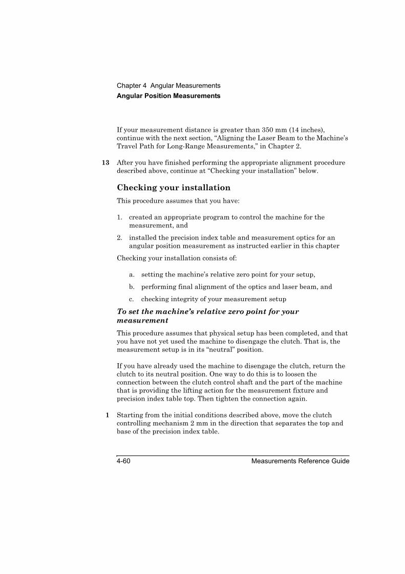
Chapter 4 Angular MeasurementsAngular Position Measurements
4-60 Measurements Reference Guide
If your measurement distance is greater than 350 mm (14 inches), continue with the next section, “Aligning the Laser Beam to the Machine’s Travel Path for Long-Range Measurements,” in Chapter 2.
13 After you have finished performing the appropriate alignment procedure described above, continue at “Checking your installation” below.
Checking your installationThis procedure assumes that you have:
1. created an appropriate program to control the machine for the measurement, and
2. installed the precision index table and measurement optics for an angular position measurement as instructed earlier in this chapter
Checking your installation consists of:
a. setting the machine’s relative zero point for your setup,
b. performing final alignment of the optics and laser beam, and
c. checking integrity of your measurement setup
To set the machine’s relative zero point for your measurementThis procedure assumes that physical setup has been completed, and that you have not yet used the machine to disengage the clutch. That is, the measurement setup is in its “neutral” position.
If you have already used the machine to disengage the clutch, return the clutch to its neutral position. One way to do this is to loosen the connection between the clutch control shaft and the part of the machine that is providing the lifting action for the measurement fixture and precision index table top. Then tighten the connection again.
1 Starting from the initial conditions described above, move the clutch controlling mechanism 2 mm in the direction that separates the top and base of the precision index table.
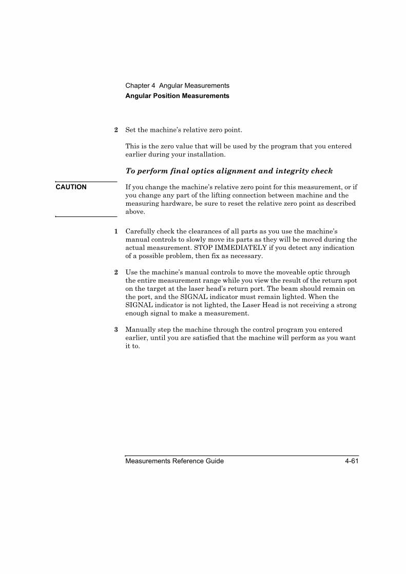
Chapter 4 Angular MeasurementsAngular Position Measurements
Measurements Reference Guide 4-61
2 Set the machine’s relative zero point.
This is the zero value that will be used by the program that you entered earlier during your installation.
To perform final optics alignment and integrity check
CAUTION If you change the machine’s relative zero point for this measurement, or if you change any part of the lifting connection between machine and the measuring hardware, be sure to reset the relative zero point as described above.
1 Carefully check the clearances of all parts as you use the machine’s manual controls to slowly move its parts as they will be moved during the actual measurement. STOP IMMEDIATELY if you detect any indication of a possible problem, then fix as necessary.
2 Use the machine’s manual controls to move the moveable optic through the entire measurement range while you view the result of the return spot on the target at the laser head’s return port. The beam should remain on the port, and the SIGNAL indicator must remain lighted. When the SIGNAL indicator is not lighted, the Laser Head is not receiving a strong enough signal to make a measurement.
3 Manually step the machine through the control program you entered earlier, until you are satisfied that the machine will perform as you want it to.

Chapter 4 Angular MeasurementsAngular Position Measurements
4-62 Measurements Reference Guide
Controlling the machine during the measurementBecause of the variety of controllers, it is not possible to present specific instructions for any particular one here. Apply the information presented here to your measurement situation.
As described earlier in this manual chapter, making a measurement consists of these activities:
1. Disengaging the precision index table top from its base.
For the hardware described in this manual chapter, disengagement requires 2 mm (0.08 inch) of movement from the “neutral” closed position. (See Figure 4-31.)
2. Rotating the precision index table’s base with respect to its top.
Although the optic mounted on the table is considered the “moveable” optic, its movement is minimal, compared to some other applications.
3. Engaging the precision index table top and base, and applying a clamping force to disengage the clutch and ensure good seating of the two parts of the table.
For the hardware described in this chapter, engagement requires moving the clutch control shaft 1.0 mm (0.04 inch) past the “neutral” closed position. (See Figure 4-31.)
4. Commanding the Agilent 5530 calibrator to record the measurement data.
Manually stepping through the machine control programStep through your machine control program manually before you run it automatically. While you are doing this, be sure to check the physical integrity of your setup, to be sure the program has not introduced any problems you did not encounter during your earlier manual check. Fix any problem that you detect.

Chapter 4 Angular MeasurementsAngular Position Measurements
Measurements Reference Guide 4-63
Running the machine control programAfter your program has passed your manual operation check, run it automatically. While you are doing this, you can also check to be sure you have set the Agilent 5530 calibrator to record data at the appropriate times. Be sure your program has enough dwell time for the Agilent 5530 to record an appropriate value.
Making the measurementIn this procedure, you make automatic measurements as you rotate the precision index table’s base. If you are using sensors, make sure they are properly placed and the software is set up correctly. (Refer to the Agilent 5530 Getting Started Guide for complete instructions on using the software and the sensors.)
This section explains how to make measurements using the Record button in the software and the optional remote control unit. See Chapter 1, “Planning Your Measurements,” for a description of other triggering methods.
To make the measurement, follow these steps:
1 Perform one measurement cycle, to place the measurement optic at its start position.
2 On the Set Up Laser: ANGULAR window, select Set Up Meas.
The Set Up Measurement: ANGULAR screen is displayed (Figure 4-31).
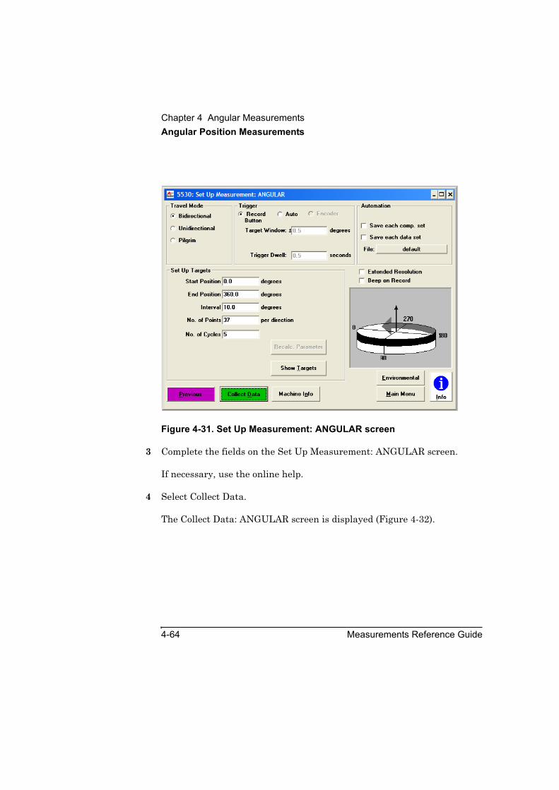
Chapter 4 Angular MeasurementsAngular Position Measurements
4-64 Measurements Reference Guide
Figure 4-31. Set Up Measurement: ANGULAR screen
3 Complete the fields on the Set Up Measurement: ANGULAR screen.
If necessary, use the online help.
4 Select Collect Data.
The Collect Data: ANGULAR screen is displayed (Figure 4-32).

Chapter 4 Angular MeasurementsAngular Position Measurements
Measurements Reference Guide 4-65
Figure 4-32. Collect Data: ANGULAR screen
5 On the Collect Data: ANGULAR screen, select Reset Position.
This tells the Agilent 5530 calibrator that the current position of the moveable optic (the machine’s relative zero point) is the “zero” point from which all angular positions will be measured.
If necessary, use the online help to complete the rest of the fields on this screen.
6 Move the precision index table’s base to the first measurement point.
7 Select Record.
If you are using the optional remote control unit, press the Record button.
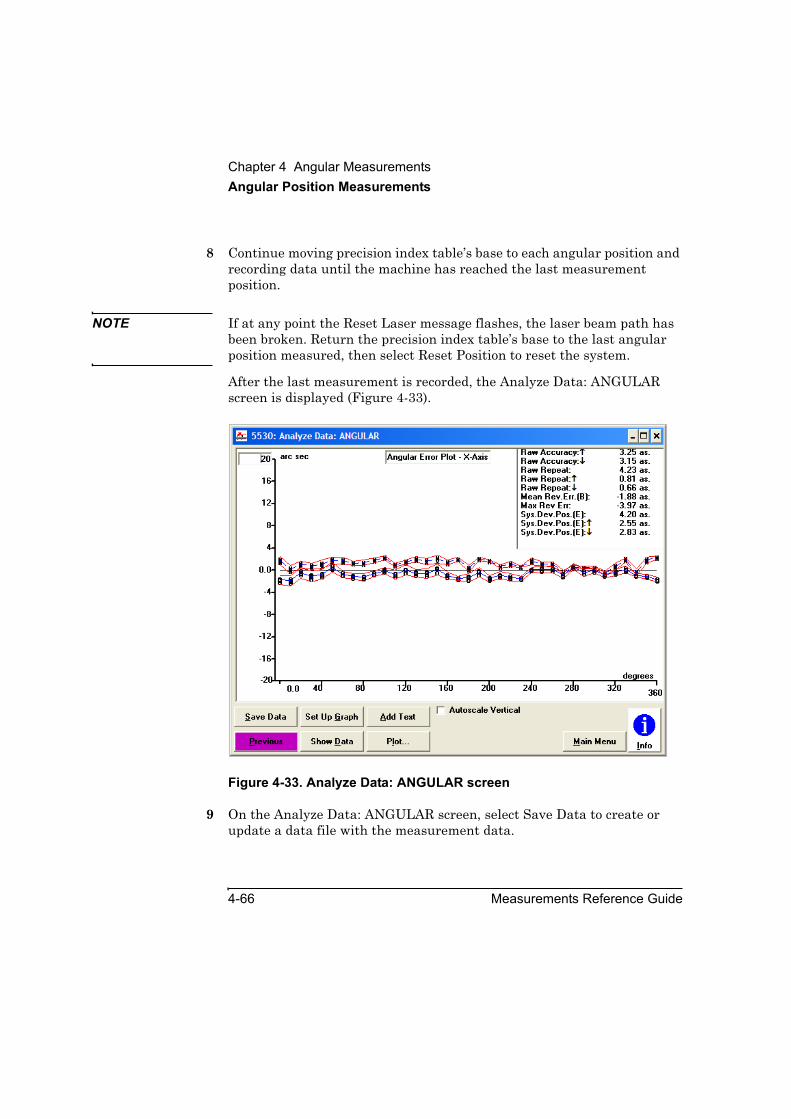
Chapter 4 Angular MeasurementsAngular Position Measurements
4-66 Measurements Reference Guide
8 Continue moving precision index table’s base to each angular position and recording data until the machine has reached the last measurement position.
NOTE If at any point the Reset Laser message flashes, the laser beam path has been broken. Return the precision index table’s base to the last angular position measured, then select Reset Position to reset the system.
After the last measurement is recorded, the Analyze Data: ANGULAR screen is displayed (Figure 4-33).
Figure 4-33. Analyze Data: ANGULAR screen
9 On the Analyze Data: ANGULAR screen, select Save Data to create or update a data file with the measurement data.

Chapter 4 Angular MeasurementsAngular Position Measurements
Measurements Reference Guide 4-67
Refer to the Agilent 5530 Getting Started Guide and online help for more information about using this screen. Otherwise, you are finished making the measurement.
Storing the hardwareReturn the angular position measurement kit components to the kit case when you have finished using them.
NOTE Before you store the precision index table:
1. Install the locking ring and bolt to hold the top and bottom together. Tighten the bolt securely.
2. After performing step 1, disengage the locking loops. This helps extend their useful life.
MaintenancePrecision index tableThe precision index table’s top and base have 360 matching teeth comprising a Hirth coupling. For best performance of the table, these teeth should be as clean as possible. You should visually inspect the teeth each time you use the table. The procedure below is recommended for cleaning Hirth coupling teeth.
WARNING BE SURE TO WEAR APPROPRIATE PROTECTIVE SHIELDING AND CLOTHING WHEN WORKING WITH COMPRESSED AIR AND ACETONE.
1 With the precision index table’s top and bottom separated, use compressed air to blow loose material from the Hirth coupling teeth.
2 If necessary, use an acid brush to remove material from the teeth.
3 If necessary, use acetone and the acid brush to remove material from the teeth.

Chapter 4 Angular MeasurementsAngular Position Measurements
4-68 Measurements Reference Guide
4 Rejoin the precision index table’s top and base, and use the locking loops to hold them together. If you will be storing the table, be sure to read the storage instructions above.
ClutchThe angular position measurements fixture’s clutch uses a nonmetallic washer glued to the end of the clutch control shaft. Occasionally, due to wear or contamination, you may have to clean or replace this washer. The procedures to do this are given below.
Disassembly
1 Remove the fixture from the precision index table, if necessary.
2 Remove any optic mounted in the fixture, if necessary.
NOTE The clutch spring exerts slight pressure between the retainer ring and the fixture’s top plate.
3 Remove the four M4 hex-drive cap-head screws that fasten the clutch retainer ring to the top plate.
4 Remove the clutch shaft from the retainer ring.
5 Perform the cleaning or replacement procedures below.
Cleaning the clutch washer
1 If necessary, perform the disassembly procedure above.
2 Using suitable solvent such as soap, wash, then dry the clutch washer and its mating surface on the underside of the clutch retainer ring. Be careful to thoroughly dry these parts and not to contaminate their surfaces with fingerprints or anything else that may act as a lubricant.
3 Replace the clutch control shaft in the retainer ring and re-attach the retainer ring to the fixture’s top plate. Only slight pressure is required to overcome the pressure of the clutch spring that tends to push the ring and plate apart.
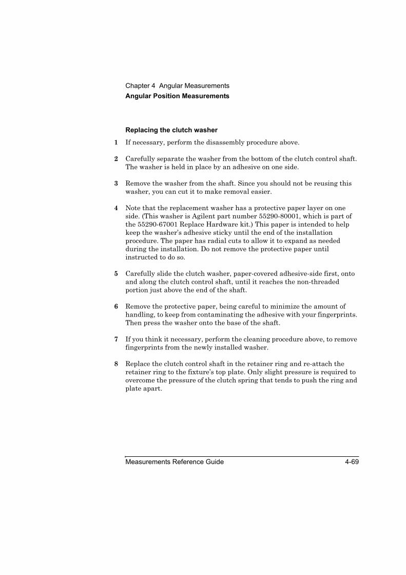
Chapter 4 Angular MeasurementsAngular Position Measurements
Measurements Reference Guide 4-69
Replacing the clutch washer
1 If necessary, perform the disassembly procedure above.
2 Carefully separate the washer from the bottom of the clutch control shaft. The washer is held in place by an adhesive on one side.
3 Remove the washer from the shaft. Since you should not be reusing this washer, you can cut it to make removal easier.
4 Note that the replacement washer has a protective paper layer on one side. (This washer is Agilent part number 55290-80001, which is part of the 55290-67001 Replace Hardware kit.) This paper is intended to help keep the washer’s adhesive sticky until the end of the installation procedure. The paper has radial cuts to allow it to expand as needed during the installation. Do not remove the protective paper until instructed to do so.
5 Carefully slide the clutch washer, paper-covered adhesive-side first, onto and along the clutch control shaft, until it reaches the non-threaded portion just above the end of the shaft.
6 Remove the protective paper, being careful to minimize the amount of handling, to keep from contaminating the adhesive with your fingerprints. Then press the washer onto the base of the shaft.
7 If you think it necessary, perform the cleaning procedure above, to remove fingerprints from the newly installed washer.
8 Replace the clutch control shaft in the retainer ring and re-attach the retainer ring to the fixture’s top plate. Only slight pressure is required to overcome the pressure of the clutch spring that tends to push the ring and plate apart.
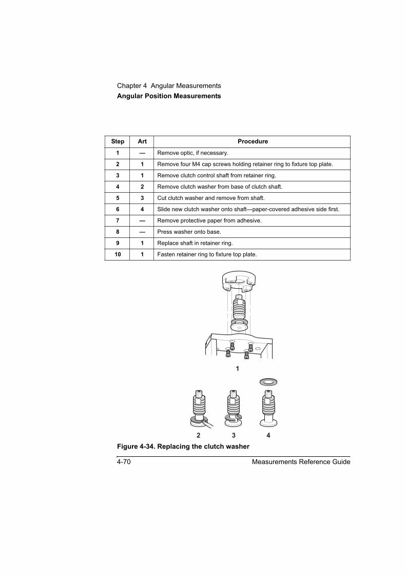
Chapter 4 Angular MeasurementsAngular Position Measurements
4-70 Measurements Reference Guide
Figure 4-34. Replacing the clutch washer
Step Art Procedure
1 — Remove optic, if necessary.
2 1 Remove four M4 cap screws holding retainer ring to fixture top plate.
3 1 Remove clutch control shaft from retainer ring.
4 2 Remove clutch washer from base of clutch shaft.
5 3 Cut clutch washer and remove from shaft.
6 4 Slide new clutch washer onto shaft—paper-covered adhesive side first.
7 — Remove protective paper from adhesive.
8 — Press washer onto base.
9 1 Replace shaft in retainer ring.
10 1 Fasten retainer ring to fixture top plate.
1
2 3 4

Chapter 4 Angular MeasurementsAngular Position Measurements
Measurements Reference Guide 4-71
Clutch breakaway nutIf the clutch breakaway-nut breaks, order a replacement clutch breakaway-nut (Agilent part number 55290-67002).
CAUTION To prevent damage to your machine or the measurement apparatus, do not use any other type of device in place of the clutch breakaway-nut.
The clutch breakaway-nut O-ring is provided as a reminder to loosen the clutch breakaway-nut before you make a measurement. It does not contribute to the strength of the breakaway nut itself. If the O-ring breaks or is lost, you may continue to use the breakaway nut. The O-ring is not separately replaceable; it is supplied as part of the clutch breakaway-nut (Agilent part number 55290-67002).

Chapter 4 Angular MeasurementsAngular Position Measurements
4-72 Measurements Reference Guide

5
Straightness Measurements

Chapter 5 Straightness MeasurementsIntroduction
5-2 Measurements Reference Guide
IntroductionThis chapter explains how to make straightness measurements that allow you to determine if a machine’s moveable part is moving along a straight path. Before performing the procedures described in this chapter, you must fully understand and know how to perform the procedures presented in the Agilent 5530 Getting Started Guide. For operating specifications for straightness measurement optics, see Appendix A.
Straightness and squareness measurements are usually done together, since a squareness measurement is actually two straightness measurements perpendicular to each other.
The procedures in this chapter explain how to make straightness measurements only. Follow them in the event that you are not going to combine straightness and squareness measurements.
If you plan to make straightness and squareness measurements, you can perform the straightness measurements as part of a squareness measurement. Depending on whether your measurements are in a horizontal or vertical plane, go to either Chapter 6, “Squareness Measurements in a Horizontal Plane,” or Chapter 7, “Squareness Measurements in a Vertical Plane.”
Figure 5-1 shows the required hardware for straightness measurements.

Chapter 5 Straightness MeasurementsIntroduction
Measurements Reference Guide 5-3Figure 5-1. Required hardware for straightness measurements
Straightness accessory kit,p/n 10776A:
1 Reflector mount, p/n 10776-67002
2 Retroreflector, p/n 10776-67001
3 Interferometer base plate, p/n 10776-20011
4 Reflector base and posts, p/n 10776-67008
************************Long range optics kit,p/n 10775A:
5 Long range reflector6 Long range
interferometer ************************
Short range optics kit, p/n 10774A:
7 Short range reflector 8 Short range
interferometer ************************9 Interferometer target,
p/n 10774-67001************************10 Height adjuster and
post, p/n 10785A************************
Turning mirror kit,p/n 10772A:
11 Turning mirror, p/n 10772-67002
12 Turning mirror base, p/n 10772-67001
7
10772A
TU
RNING MIRROR
1A10772-67002 ASSY
10785A
HEIG
HT ADJUSTER
A
2
12
11
10
9
3
5
6
8
1
4
S.R
.STRA
IGHTN
ESS REFLECTOR
1A
10774A
L.R. STRAIGHTNESS
INTERFEROMETER
1A0 0 9 0 0
L.R
.STR
AIGHTN
ESS REFLECTOR
2120A
10775A
S.R. STRAIGHTNESS
INTERFEROMETER
1A0 0 6 0 0
10776A STRAIGHTNESS ACCESSORY
10776-67001 STR. RETROREFLECTOR
SER. 2216A
10772-67001
Made in U.S.A. of domestic and foreign content
TURNING MIRROR MOUNT ASSEMBLY

Chapter 5 Straightness MeasurementsSetting Up for the Measurement
5-4 Measurements Reference Guide
Setting Up for the MeasurementIf you have not already done so, perform the following setup procedures before using the rest of the instructions in this chapter to make a straightness measurement. Refer to the Agilent 5530 Getting Started Guide for complete instructions when installing and starting the system for the first time.
1 Mount the laser head on the tripod and place the tripod near the target machine.
2 Connect the E1735A USB Axis Module and the E1736A USB Sensor Hub to the USB connectors on your PC. Connect the laser head and remote control unit to the axis module. Connect the sensors to the sensor hub.
3 Plug in and turn on all equipment.
4 Start the Agilent 10747F Metrology Software.
The Metrology Main Menu is displayed.
5 On the Metrology Main Menu, select Straightness.
The Set Up Laser: STRAIGHTNESS screen (Figure 5-2) is displayed.
Alternately, you can open an existing straightness measurement setup file by selecting Recall Data on the Main Menu.
6 Complete the fields on the Set Up Laser: STRAIGHTNESS screen.
If necessary, use the online help.

Chapter 5 Straightness MeasurementsPositioning the Laser Head and Target Machine
Measurements Reference Guide 5-5
Figure 5-2. Set Up Laser: STRAIGHTNESS screen
Positioning the Laser Head and Target MachineBefore you begin to assemble and mount optics, you must position the laser head and move the target machine to its initial position. Follow these steps:
1 Position the laser head along the axis most suitable for the measurement that you want to make (see Figure 5-3, 5-4, or 5-5).
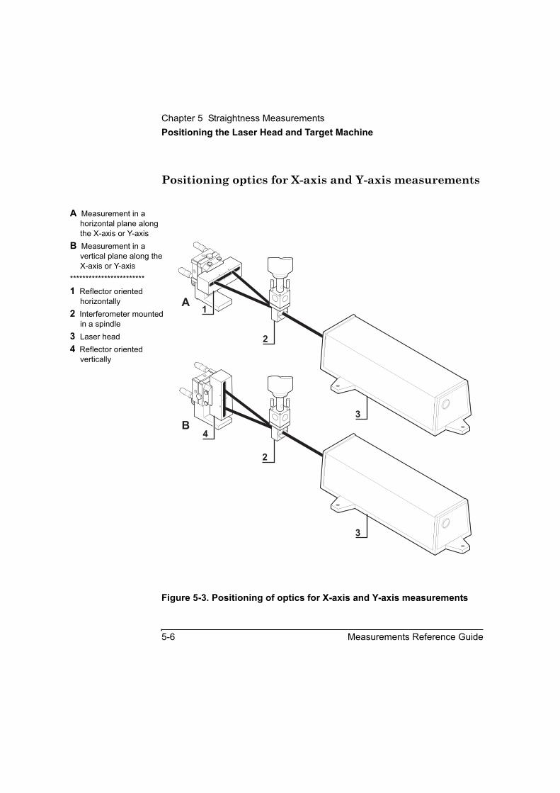
Chapter 5 Straightness MeasurementsPositioning the Laser Head and Target Machine
5-6 Measurements Reference Guide
Positioning optics for X-axis and Y-axis measurements
Figure 5-3. Positioning of optics for X-axis and Y-axis measurements
A Measurement in a horizontal plane along the X-axis or Y-axis
B Measurement in a vertical plane along the X-axis or Y-axis
************************1 Reflector oriented
horizontally2 Interferometer mounted
in a spindle3 Laser head4 Reflector oriented
vertically
1A
1A
4
2
B
A1
2
3
3

Chapter 5 Straightness MeasurementsPositioning the Laser Head and Target Machine
Measurements Reference Guide 5-7
Positioning optics for vertical Z-Axis measurements
Figure 5-4. Positioning of optics for a vertical Z-axis measurement
A Measurement perpendicular to the laser head along the Z-axis
B Measurement parallel to the laser head along the Z-axis
************************1 Interferometer assembly
mounted in a spindle2 Reflector oriented
perpendicular to the laser head
3 Laser beam4 Laser head5 Reflector oriented
parallel to laser head
A
B
10772ATURNING
M
IRR
OR
HE
W
LE
TT-PACKARD
1A
10772-67002ASSY
1A
10772A TURNINGMIRROR
HEW
LE
TT - P A C K A R D
1A
10772-67002 ASSY
1A
2
3 4
5
3
4
1
1

Chapter 5 Straightness MeasurementsPositioning the Laser Head and Target Machine
5-8 Measurements Reference Guide
Positioning optics for horizontal Z-axis measurements
Figure 5-5. Positioning of optics for a horizontal Z-axis measurement
A Measurement in a horizontal plane along the Z-axis
B Measurement in a vertical plane along the Z-axis
************************1 Interferometer assembly
oriented horizontally in a spindle
2 Interferometer assembly oriented vertically in a spindle
3 Reflector oriented vertically
4 Laser head5 Reflector oriented
horizontally
10776A STRAIGHTNESS ACCESSORY
10776A STRAIGHTNESS ACCESSORY
10776-67001 STR. RETROREFLECTOR
10776-67001 STR. RETROREFLECTOR
H E W L E T T - P A C K A R D
H E W L E T T - P A C K A R D
SER. 2216A
SER. 2216A
4
1
4
5
A
B
2
3
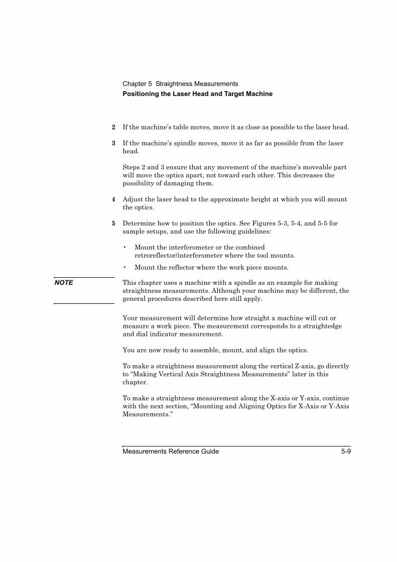
Chapter 5 Straightness MeasurementsPositioning the Laser Head and Target Machine
Measurements Reference Guide 5-9
2 If the machine’s table moves, move it as close as possible to the laser head.
3 If the machine’s spindle moves, move it as far as possible from the laser head.
Steps 2 and 3 ensure that any movement of the machine’s moveable part will move the optics apart, not toward each other. This decreases the possibility of damaging them.
4 Adjust the laser head to the approximate height at which you will mount the optics.
5 Determine how to position the optics. See Figures 5-3, 5-4, and 5-5 for sample setups, and use the following guidelines:
• Mount the interferometer or the combined retroreflector/interferometer where the tool mounts.
• Mount the reflector where the work piece mounts.
NOTE This chapter uses a machine with a spindle as an example for making straightness measurements. Although your machine may be different, the general procedures described here still apply.
Your measurement will determine how straight a machine will cut or measure a work piece. The measurement corresponds to a straightedge and dial indicator measurement.
You are now ready to assemble, mount, and align the optics.
To make a straightness measurement along the vertical Z-axis, go directly to “Making Vertical Axis Straightness Measurements” later in this chapter.
To make a straightness measurement along the X-axis or Y-axis, continue with the next section, “Mounting and Aligning Optics for X-Axis or Y-Axis Measurements.”

Chapter 5 Straightness MeasurementsMounting and Aligning Optics for X-Axis or Y-Axis Measurements
5-10 Measurements Reference Guide
Mounting and Aligning Optics for X-Axis or Y-Axis MeasurementsThis section explains how to assemble, mount, and align optics for straightness measurements along the X-axis or Y-axis.
Mounting the opticsTo assemble the optics and mount them on the machine, follow these steps:
1 Connect the interferometer to its base using the attachment screws provided (Figure 5-6).
2 Connect the post to the interferometer using either of the following methods (one method uses the height adjuster, the other does not):
• Remove the large knurled knob from the height adjuster, connect the height adjuster to the interferometer’s base plate using the attachment screws, and screw the post into the height adjuster (Figure 5–6). Use this method if you plan to make other types of measurements later; it will take less time to change the optics.
• Screw the post directly into the interferometer’s base plate (Figure 5-7).
3 Secure the post in the machine spindle.
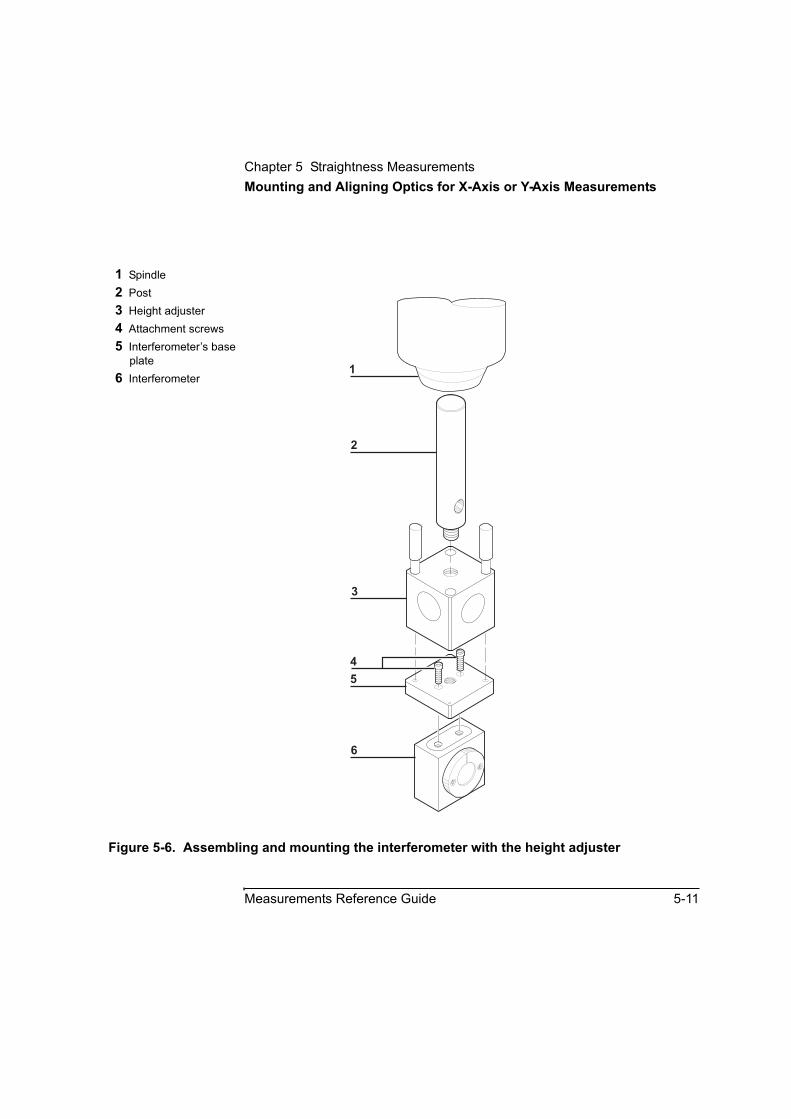
Chapter 5 Straightness MeasurementsMounting and Aligning Optics for X-Axis or Y-Axis Measurements
Measurements Reference Guide 5-11
Figure 5-6. Assembling and mounting the interferometer with the height adjuster
1 Spindle2 Post3 Height adjuster4 Attachment screws5 Interferometer’s base
plate6 Interferometer
2
3
4
5
6
1
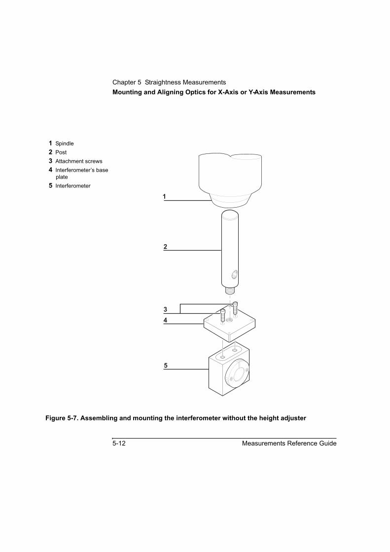
Chapter 5 Straightness MeasurementsMounting and Aligning Optics for X-Axis or Y-Axis Measurements
5-12 Measurements Reference Guide
Figure 5-7. Assembling and mounting the interferometer without the height adjuster
1 Spindle2 Post3 Attachment screws4 Interferometer’s base
plate5 Interferometer
1
2
3
4
5
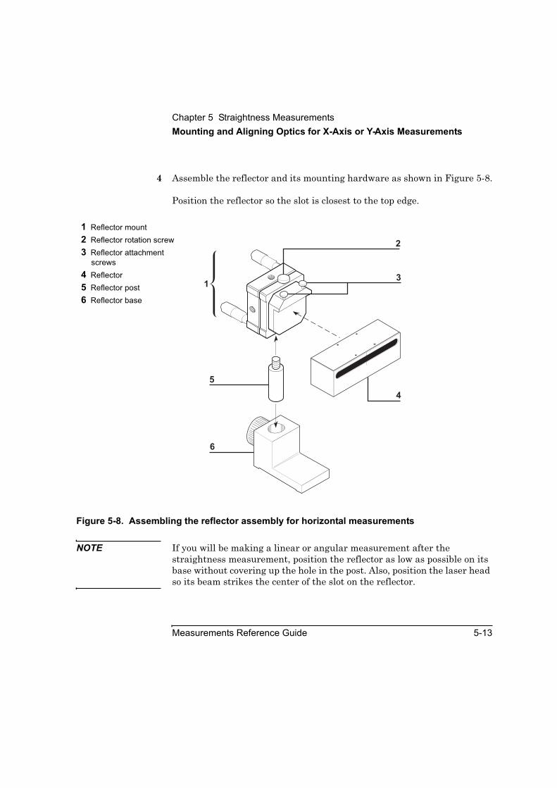
Chapter 5 Straightness MeasurementsMounting and Aligning Optics for X-Axis or Y-Axis Measurements
Measurements Reference Guide 5-13
4 Assemble the reflector and its mounting hardware as shown in Figure 5-8.
Position the reflector so the slot is closest to the top edge.
Figure 5-8. Assembling the reflector assembly for horizontal measurements
NOTE If you will be making a linear or angular measurement after the straightness measurement, position the reflector as low as possible on its base without covering up the hole in the post. Also, position the laser head so its beam strikes the center of the slot on the reflector.
1 Reflector mount2 Reflector rotation screw3 Reflector attachment
screws4 Reflector5 Reflector post6 Reflector base
13
4
5
6
2
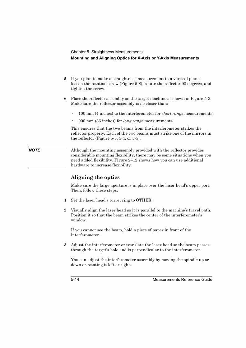
Chapter 5 Straightness MeasurementsMounting and Aligning Optics for X-Axis or Y-Axis Measurements
5-14 Measurements Reference Guide
5 If you plan to make a straightness measurement in a vertical plane, loosen the rotation screw (Figure 5-8), rotate the reflector 90 degrees, and tighten the screw.
6 Place the reflector assembly on the target machine as shown in Figure 5-3. Make sure the reflector assembly is no closer than:
• 100 mm (4 inches) to the interferometer for short range measurements
• 900 mm (36 inches) for long range measurements.
This ensures that the two beams from the interferometer strikes the reflector properly. Each of the two beams must strike one of the mirrors in the reflector (Figure 5-3, 5-4, or 5-5).
NOTE Although the mounting assembly provided with the reflector provides considerable mounting flexibility, there may be some situations when you need added flexibility. Figure 2–12 shows how you can use additional hardware to increase flexibility.
Aligning the opticsMake sure the large aperture is in place over the laser head’s upper port. Then, follow these steps:
1 Set the laser head’s turret ring to OTHER.
2 Visually align the laser head so it is parallel to the machine’s travel path. Position it so that the beam strikes the center of the interferometer’s window.
If you cannot see the beam, hold a piece of paper in front of the interferometer.
3 Adjust the interferometer or translate the laser head so the beam passes through the target’s hole and is perpendicular to the interferometer.
You can adjust the interferometer assembly by moving the spindle up or down or rotating it left or right.

Chapter 5 Straightness MeasurementsMounting and Aligning Optics for X-Axis or Y-Axis Measurements
Measurements Reference Guide 5-15
4 Lock the spindle in place, using, for example, a hose clamp and wedging material. Then, remove the target from the interferometer.
5 Gently tap the interferometer assembly to ensure that its mounting is rigid and free of vibration.
If you feel any vibration, tighten all connections in the mounting.
6 Set the laser head’s upper port to the large aperture.
7 Rotate the interferometer’s bezel (Figure 5-9) so the scribe line is perpendicular to the reflector’s slot.
Two beams should now be exiting the interferometer in a plane perpendicular to the interferometer’s slot. The beams appear as dots on the reflector. If you cannot see the beams, hold a piece of paper in front of the reflector.
Figure 5-9. Interferometer bezel with scribe line
8 Move the reflector back and forth or side to side until the dots are aligned vertically between the midpoint notches in the reflector’s slot (Figure 5-10).
By doing this, you ensure that the beams strike the junction of the two mirrors in the reflector.
1 Scribe line2 Interferometer’s window3 Interferometer’s bezel
L.R. STRAIGHTNESS
INTERFEROMETER
1A0 0 9 0 0
1
3 2
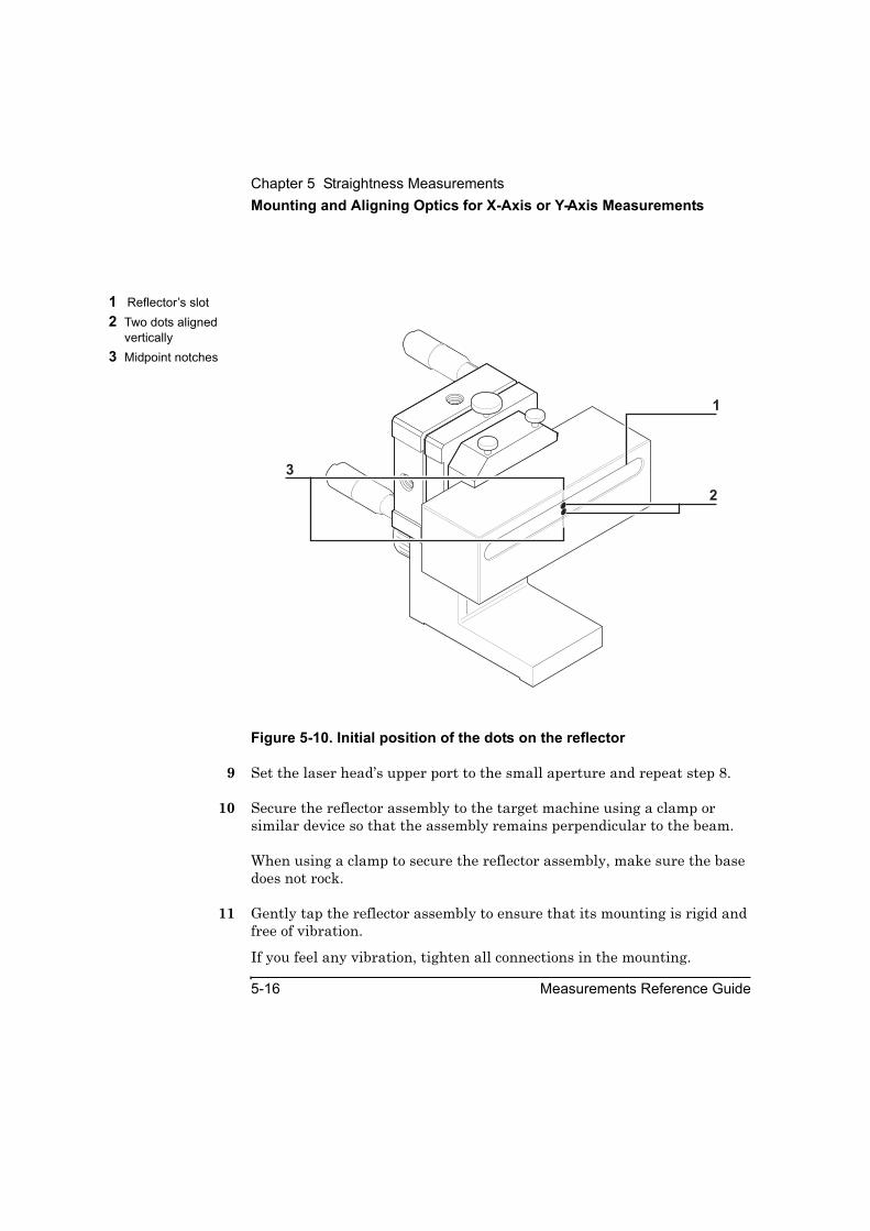
Chapter 5 Straightness MeasurementsMounting and Aligning Optics for X-Axis or Y-Axis Measurements
5-16 Measurements Reference Guide
Figure 5-10. Initial position of the dots on the reflector
9 Set the laser head’s upper port to the small aperture and repeat step 8.
10 Secure the reflector assembly to the target machine using a clamp or similar device so that the assembly remains perpendicular to the beam.
When using a clamp to secure the reflector assembly, make sure the base does not rock.
11 Gently tap the reflector assembly to ensure that its mounting is rigid and free of vibration.
If you feel any vibration, tighten all connections in the mounting.
1 Reflector’s slot2 Two dots aligned
vertically3 Midpoint notches
1
2
3

Chapter 5 Straightness MeasurementsMaking Vertical Axis Straightness Measurements
Measurements Reference Guide 5-17
You are now ready to align the laser beam to the machine’s travel path. Go directly to “Aligning the Laser Beam to the Machine’s Travel Path” later in this chapter.
Making Vertical Axis Straightness MeasurementsIf you have an optical square, you can make a vertical axis straightness measurement as part of a squareness measurement. Follow the instructions in Chapter 7, “Squareness Measurements in a Vertical Plane.”
If you do not have an optical square, refer to Figures 5-11 through 5-16 for guidance in optical setup and hardware assembly. Adapt the procedure in “Mounting and Aligning Optics for X-Axis or Y-Axis Measurements” as required.
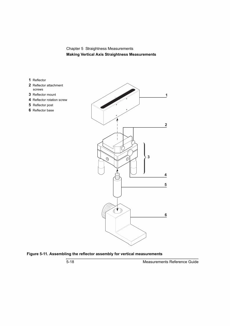
Chapter 5 Straightness MeasurementsMaking Vertical Axis Straightness Measurements
5-18 Measurements Reference Guide
Figure 5-11. Assembling the reflector assembly for vertical measurements
1 Reflector2 Reflector attachment
screws3 Reflector mount4 Reflector rotation screw5 Reflector post6 Reflector base
1
2
3
4
6
5
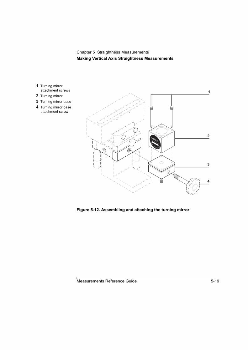
Chapter 5 Straightness MeasurementsMaking Vertical Axis Straightness Measurements
Measurements Reference Guide 5-19
Figure 5-12. Assembling and attaching the turning mirror
1 Turning mirror attachment screws
2 Turning mirror 3 Turning mirror base4 Turning mirror base
attachment screw
10772ATURNING
M
IRR
OR 1A
10772-67002ASSY
1
2
3
4

Chapter 5 Straightness MeasurementsMaking Vertical Axis Straightness Measurements
5-20 Measurements Reference Guide
Figure 5-13. Attaching the interferometer to the retroreflector
Figure 5-14. Adjusting screw on the turning mirror’s base
1 Attachment screws2 Retroreflector3 Interferometer
2
1
1A
3
1 Adjusting screw
10772ATURNING
M
IRR
OR
1A10772-67002ASSY
1

Chapter 5 Straightness MeasurementsMaking Vertical Axis Straightness Measurements
Measurements Reference Guide 5-21
Figure 5-15. Alignment ring on the retroreflector
Figure 5-16. Initial position of the dots on the reflector
1 Alignment ring2 Interferometer3 Retroreflector 1
L.R. STRAIGHTNESS
INTERFEROMETER
1A0 0 9 0 0
2
3
10776A STRAIGHTNESS ACCESSORY
10776-67001 STR. RETROREFLECTOR
SER. 2216A
1 Two dots
10772ATURNING
M
IRR
OR
1A10772-67002ASSY
1

Chapter 5 Straightness MeasurementsAligning the Laser Beam to the Machine’s Travel Path
5-22 Measurements Reference Guide
Aligning the Laser Beam to the Machine’s Travel PathBefore using the following instructions, make sure the turret ring on the laser head is set to OTHER and the small opening is in place over the upper aperture.
To align the laser beam to the machine’s travel path, follow these steps:
1 Attach a target to the moving optic.
• If the interferometer is the moving optic, attach the round target to the side of the interferometer facing the laser head so the beam passes through the target’s hole.
• If the reflector is the moving optic, remove the interferometer. Then, attach the rectangular target to the side of the reflector facing the laser head.
2 While watching the two dots on the reflector’s surface, move the moveable optic away from its initial position.
As you move the optic, the two dots in the reflector’s slot separate (Figure 5-10). Your goal is to make sure that (1) they remain in the plane of the midpoint notches on the reflector, and (2) both dots remain at an equal distance from the center of the slot.
• If the two dots on the reflector’s surface begin to move out of this pattern, tilt the laser head vertically or rotate it left or right to adjust the dots to their correct position.
• If you are using a retroreflector and the beam moves out of the alignment ring on the retroreflector’s surface, translate the laser head vertically and horizontally until the beam passes through the alignment ring.

Chapter 5 Straightness Measurements
Aligning the Laser Beam to the Machine’s Travel Path
Measurements Reference Guide 5-23
3 Repeat step 2 until the machine reaches the end of the travel path.
The laser beam is now aligned to the machine’s travel path. Your goal in the rest of this procedure is to ensure the following:
• One beam enters the interferometer.
• Two beams exit the interferometer and strike the two mirrors in the reflector equally spaced from the midpoint notches.
• Two beams enter the interferometer from the reflector.
4 While watching the front of the laser head, rotate the interferometer’s bezel so that two dots overlap each other over the upper port on the laser head.
5 If you cannot see the dots, follow these steps:
a. In the middle of a piece of paper, cut a round hole the size of the interferometer’s lens.
b. Place the paper between the reflector and the interferometer, close to the interferometer so that the beams pass through the hole in the paper.
Be sure the paper does not block the beam from the interferometer to the reflector.
You should see either one or two dots on the paper.
c. If necessary, adjust the tilt of the reflector using the two large micrometer knobs on the back of the reflector’s mounting until the dots disappear into the interferometer.
d. Remove the paper.
Two dots now appear on the front of the laser head.
e. Slowly turn the interferometer’s bezel until the dots overlap.
6 Adjust the reflector’s tilt until the overlapping dots are centered on the laser head’s upper port and create a small halo around it.
Chapter 5 Straightness Measurements
Checking the Alignment for Beam Strength
5-24 Measurements Reference Guide
7 Set the laser head’s turret ring to STRAIGHT.
8 Set the laser head’s upper port to the large aperture.
9 Slowly turn the bezel until the beam strength displayed on the Set Up Laser: STRAIGHTNESS screen is at least 60 percent.
Make sure you do not turn the bezel too far.
10 Adjust the reflector’s tilt until you achieve the highest beam strength possible.
11 Remove the target from the moveable optic.
12 If you had to remove the interferometer, reattach it to its mounting.
You are now ready to check the alignment for beam strength.
Checking the Alignment for Beam Strength
Before checking the alignment for laser beam strength, ensure that the moveable optic is at its initial position. Then, follow these steps:
1 Set the laser head’s upper port to the large aperture.
2 Move the moveable optic along the travel path and check the laser beam strength indicator on the Set Up Laser: STRAIGHTNESS screen.
If the beam strength is at least 60 percent, go directly to “Making the Measurement.” If the beam strength indicator falls below 60 percent, ensure the following:
• The reflector is positioned so each of the two beams from the interferometer strike one of the mirrors in the reflector (Figure 5-3, 5-4, or 5-5). If they do not, repeat the steps in “Aligning the optics.”
Chapter 5 Straightness Measurements
Making the Measurement
Measurements Reference Guide 5-25
• The optics are securely mounted. If are not, remount them and repeat the steps in “Aligning the optics.”
• The optics are clean. To clean the optics, follow the directions in the Agilent 5530 Getting Started Guide.
If you used the preceding methods and you still cannot obtain 60 percent beam strength, call your local support person or Agilent Technologies customer support. Refer to the back of this guide for a list of Agilent Technologies service and support centers.
Making the Measurement
In this procedure, you make manual measurements as you advance the machine’s moveable part. The instructions explain how to make measurements using either the Record button displayed on the screen or the optional remote control unit. See Chapter 1, “Planning Your Measurements,” for a description of other triggering methods.
To make the measurement, follow these steps:
1 Move the moveable optic so it is at the initial position.
2 On the Set Up Laser: STRAIGHTNESS screen, select Set Up Meas.
The Set Up Measurement: STRAIGHTNESS screen is displayed (Figure 5-17).
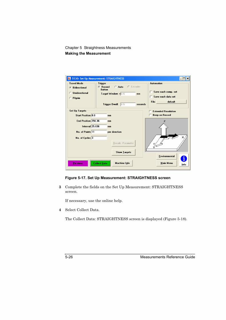
Chapter 5 Straightness MeasurementsMaking the Measurement
5-26 Measurements Reference Guide
Figure 5-17. Set Up Measurement: STRAIGHTNESS screen
3 Complete the fields on the Set Up Measurement: STRAIGHTNESS screen.
If necessary, use the online help.
4 Select Collect Data.
The Collect Data: STRAIGHTNESS screen is displayed (Figure 5-18).

Chapter 5 Straightness MeasurementsMaking the Measurement
Measurements Reference Guide 5-27
Figure 5-18. Collect Data: STRAIGHTNESS screen
5 On the Collect Data: STRAIGHTNESS screen, select Reset Position.
This tells the system that the current position of the reflector is the “zero” point from which all distances will be measured.
If necessary, use the online help to complete the rest of the fields on this screen.
6 Move the machine to the first measurement point.

Chapter 5 Straightness MeasurementsMaking the Measurement
5-28 Measurements Reference Guide
7 Select Record.
If you are using the optional remote control unit, press the Record button.
8 Continue moving the machine to each point and recording measurements until the machine has reached the last measurement position.
NOTE If at any point the Reset Laser message flashes, the laser beam path has been broken. Move the retroreflector back to the last position measured before the beam was broken, then select Reset Laser to reset the system.
After you record the last measurement, the Analyze Data: STRAIGHTNESS screen is displayed (Figure 5-19).
Figure 5-19. Analyze Data: STRAIGHTNESS screen
9 Select Save Data to create or update a data file with the measurement data. Refer to the Agilent 5530 Getting Started Guide for more information about using this screen. Otherwise, you are finished making the measurement.

6
Squareness Measurements in a Horizontal Plane
Chapter 6 Squareness Measurements in a Horizontal PlaneIntroduction
6-2 Measurements Reference Guide
IntroductionThis chapter explains how to make squareness measurements in a horizontal plane. These measurements allow you to determine if two machine axes are oriented, and move, perpendicular to each other. An example of a machine with two perpendicular axes is a milling machine with a horizontal spindle and a bed that moves perpendicular to the spindle.
Chapter 7, “Squareness Measurements in a Vertical Plane,” explains how to determine if two machine axes that are perpendicular to each other in a vertical plane are oriented, and move, perpendicular to each other.
Before performing the procedures described in this chapter, you must fully understand and know how to perform the procedures presented in the Agilent 5530 Getting Started Guide.
For operating specifications for squareness measurement optics, see Appendix A.
Figure 6-1 shows the required hardware for squareness measurements in a horizontal plane.

Chapter 6 Squareness Measurements in a Horizontal PlaneIntroduction
Measurements Reference Guide 6-3
Figure 6-1. Required hardware for squareness measurements in a horizontal plane
Optical square kit,p/n 10777A
1 Optical square base2 Optical square************************
Straightness accessory kit,p/n 10776A
3 Reflector mount, p/n 10776-67002
4 Straightness retroreflector, p/n 10776-67001
5 Interferometer base plate, p/n 10776-20011
6 Reflector base and posts************************
Long range optics kit,p/n 10775A
7 Long range reflector8 Long range
interferometer************************
Short range optics kit, p/n 10774A
9 Short range reflector10 Short range
interferometer ************************11 Interferometer target,
p/n 10774-67001************************12 Height adjuster and
post, p/n 10785A13 Reflector target,
p/n 10774-20021 10
S.R
.STRA
IGHTN
ESS REFLECTOR
1A
10774A
L.R. STRAIGHTNESS
INTERFEROMETER
1A0 0 9 0 0
4
5
3
7
8
9
1
12
11
6
290
OPTICAL S
QUARE
10777A
HEWLETT-P
ACKARD
10785A
HEIG
HT ADJUSTER
S.R. STRAIGHTNESS
INTERFEROMETER
1A0 0 6 0 0
13
L.R
.STRA
IGHTN
ESS REFLECTOR
2120A
10775A
10776A STRAIGHTNESS ACCESSORY
10776-67001 STR. RETROREFLECTOR
SER. 2216A

Chapter 6 Squareness Measurements in a Horizontal PlaneSetting Up for the Measurement
6-4 Measurements Reference Guide
Setting Up for the MeasurementIf you have not already done so, perform the following setup procedures before using the rest of the instructions in this chapter to make a squareness measurement. Refer to the Agilent 5530 Getting Started Guidefor complete instructions when installing and starting the system for the first time.
1 Mount the laser head on the tripod and place the tripod near the target machine.
2 Connect the E1735A USB Axis Module and the E1736A USB Sensor Hub to the USB connectors on your PC. Connect the laser head and remote control unit to the axis module. Connect the sensors to the sensor hub.
3 Plug in and turn on all equipment.
4 Start the Agilent 10747F Metrology Software.
The Metrology Main Menu is displayed.
5 On the Metrology Main Menu, select Other Meas.
The Other Measurements screen is displayed (Figure 6-2).
Alternately, you can open an existing squareness setup file by selecting Recall Data on the Main Menu.

Chapter 6 Squareness Measurements in a Horizontal PlaneSetting Up for the Measurement
Measurements Reference Guide 6-5
Figure 6-2. Other Measurements screen
6 On the Other Measurements screen, select Squareness.
The Set Up Laser: SQUARENESS screen is displayed (Figure 6-3).
7 Complete the fields on the Set Up Laser: SQUARENESS screen.
If necessary, use the online help.
You are now ready to position the laser head and target machine.
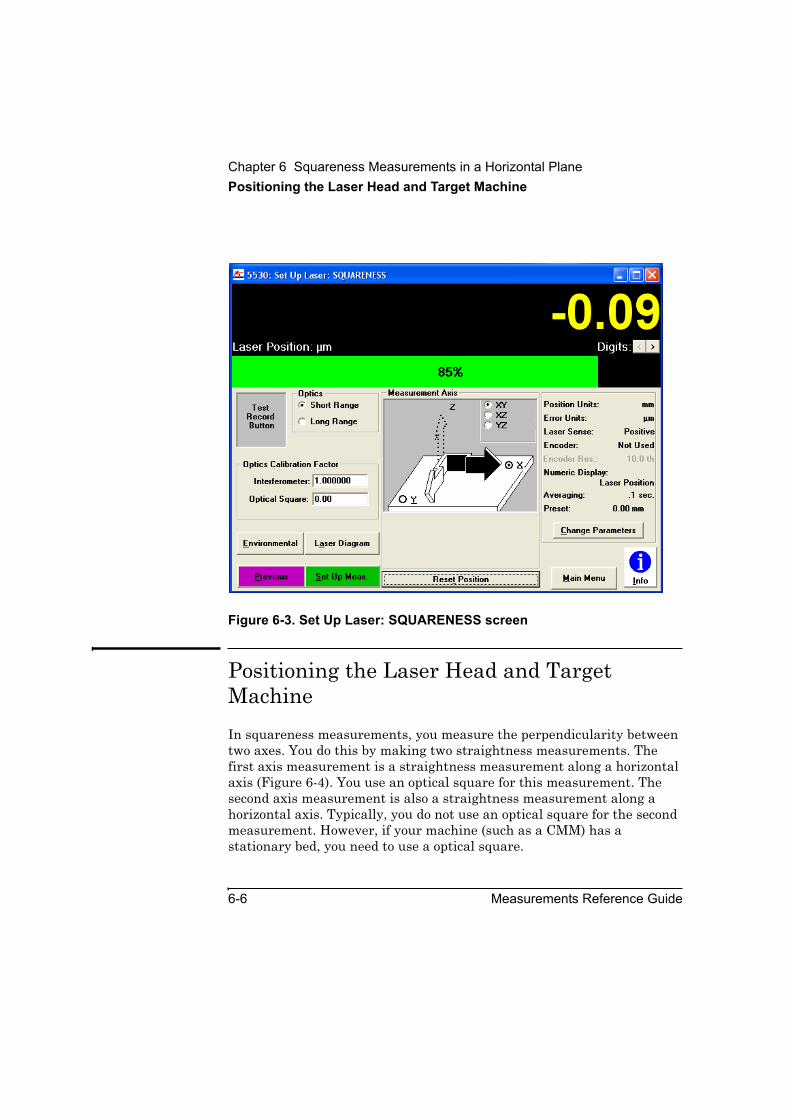
Chapter 6 Squareness Measurements in a Horizontal PlanePositioning the Laser Head and Target Machine
6-6 Measurements Reference Guide
Figure 6-3. Set Up Laser: SQUARENESS screen
Positioning the Laser Head and Target MachineIn squareness measurements, you measure the perpendicularity between two axes. You do this by making two straightness measurements. The first axis measurement is a straightness measurement along a horizontal axis (Figure 6-4). You use an optical square for this measurement. The second axis measurement is also a straightness measurement along a horizontal axis. Typically, you do not use an optical square for the second measurement. However, if your machine (such as a CMM) has a stationary bed, you need to use a optical square.

Chapter 6 Squareness Measurements in a Horizontal PlanePositioning the Laser Head and Target Machine
Measurements Reference Guide 6-7
Before you begin to assemble and mount the optics, you must position the laser head and move the moveable part of the target machine to its start position. Follow these steps:
This chapter uses a machine with a spindle as an example for making squareness measurements. Although your machine may be different, the general procedures described here still apply.
1 Position the laser head for the first axis measurement (Figure 6-4 or 6-5).
The way you position the laser head depends on whether the machine has a vertical or horizontal spindle.
2 Adjust the laser head to the approximate height at which you will mount the optics.
3 Determine how to position the optics. See Figure 6-4 or 6-5 for sample setups, and use the following guidelines:
• A machine with a vertical spindle typically has room to mount both the reflector and the optical square on the table (Figure 6-4). If yours does not, you will need to improvise some kind of table extension.
• Typically, a machine with a horizontal spindle allows you to position the laser head and optics as shown in Figure 6-5.
You are now ready to assemble, mount, and align the optical square and interferometer assembly for the first axis measurement.

Chapter 6 Squareness Measurements in a Horizontal PlanePositioning the Laser Head and Target Machine
6-8 Measurements Reference Guide
Figure 6-4. First axis positioning of optics on a machine with a vertical spindle
1 Reflector oriented horizontally
2 Optical square oriented horizontally
3 Interferometer mounted in a spindle
4 Laser head
90
OPTICAL SQUARE
10777A
HEWLETT-PACKARD
9090
2
3
4
1
1A

Chapter 6 Squareness Measurements in a Horizontal PlanePositioning the Laser Head and Target Machine
Measurements Reference Guide 6-9
Figure 6-5. First axis positioning of optics on a machine with a horizontal spindle
1 Spindle2 Retroreflector mounted
horizontally in a spindle3 Interferometer4 Optical square oriented
horizontally5 Laser head6 Reflector oriented
horizontally
10776ASTRAIGHTNESS ACCESSORY
10776ASTRAIGHTNESSACCESSORY
10776-67001 STR. RETROREFLECTOR
10776-67001STR.RETROREFLECTOR
HEWLETT-PACKARD
HEWLETT-PACKARD
SER. 2216A
SER.2216A
90
OPTICAL S
QUARE
10777A
HEWLETT-P
ACKARD
90903
6
1 2
4 5

Chapter 6 Squareness Measurements in a Horizontal PlaneMounting and Aligning the Optical Square and Interferometer for the First Axis Measurement
6-10 Measurements Reference Guide
Mounting and Aligning the Optical Square and Interferometer for the First Axis MeasurementIf your machine has a vertical spindle, continue with the instructions in the next section, “Mounting and aligning optics on a machine with a vertical spindle.”
If your machine has a horizontal spindle, go directly to the instructions in “Mounting and aligning optics on a machine with a horizontal spindle” in this chapter.
Mounting and aligning optics on a machine with a vertical spindle This section explains how to assemble, mount, and align the optical square and interferometer on a machine with a vertical spindle.
Mounting the optics To assemble the optical square and interferometer and mount them on the machine, follow these steps:
1 Attach the optical square to its mount using the attachment screw (Figure 6-6).
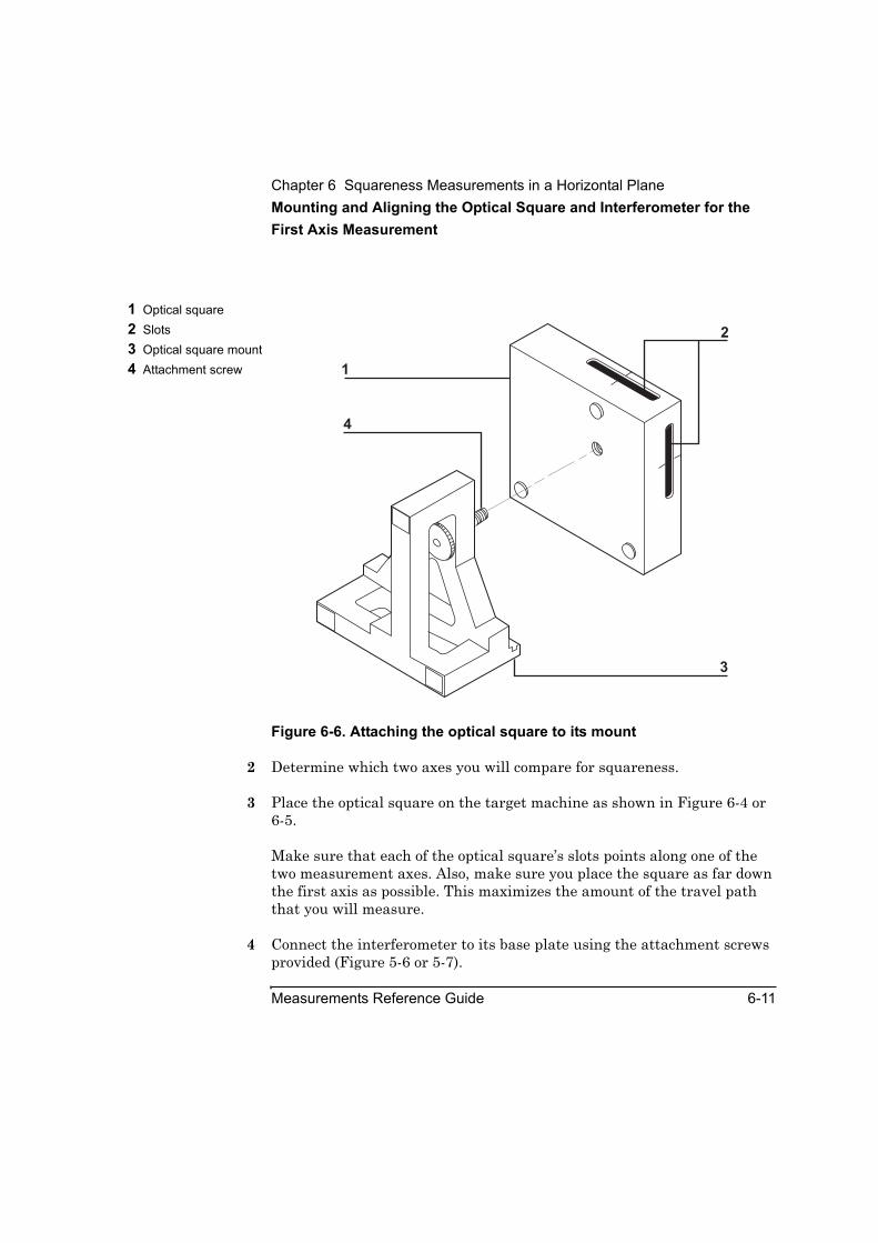
Chapter 6 Squareness Measurements in a Horizontal PlaneMounting and Aligning the Optical Square and Interferometer for the First Axis Measurement
Measurements Reference Guide 6-11
Figure 6-6. Attaching the optical square to its mount
2 Determine which two axes you will compare for squareness.
3 Place the optical square on the target machine as shown in Figure 6-4 or 6-5.
Make sure that each of the optical square’s slots points along one of the two measurement axes. Also, make sure you place the square as far down the first axis as possible. This maximizes the amount of the travel path that you will measure.
4 Connect the interferometer to its base plate using the attachment screws provided (Figure 5-6 or 5-7).
1 Optical square2 Slots3 Optical square mount4 Attachment screw 1
2
4
3
Chapter 6 Squareness Measurements in a Horizontal PlaneMounting and Aligning the Optical Square and Interferometer for the First Axis Measurement
6-12 Measurements Reference Guide
5 Connect the post to the interferometer using either of the following methods (one method uses the height adjuster; the other does not):
• Remove the large knurled knob from the height adjuster, connect the height adjuster to the interferometer base using the attachment screws, and screw the post into the height adjuster (Figure 5-6). Because this method makes it easier to change optics, use it if you plan to make linear or angular measurements later on.
• Screw the post directly into the interferometer’s base plate (Figure 5-7).
6 Position the interferometer assembly close enough to the optical square to line up the center of the interferometer’s window with the midpoint notches on the optical square.
7 Orient the interferometer so it is perpendicular to the beam from the laser head.
8 Position the optical square so that:
• the side facing the interferometer is parallel to the interferometer, and
• the optical square is square to the machine.
You are now ready to align the optics.
Aligning the opticsTo align the optics, follow these steps:
1 Set the laser head’s upper port to the large aperture by turning the upper aperture control (Figure 2-13).
2 Set the turret ring to OTHER.
This provides the highest beam intensity possible.
3 Visually align the laser head so it is parallel to the machine’s table. Position it so that the beam strikes the center of the interferometer’s window.If you cannot see the beam, hold a piece of paper in front of the interferometer.

Chapter 6 Squareness Measurements in a Horizontal PlaneMounting and Aligning the Optical Square and Interferometer for the First Axis Measurement
Measurements Reference Guide 6-13
4 Attach the target to the interferometer on the side facing the laser head. Make sure that the edges of the target line up as evenly as possible with the edges of the interferometer’s bezel (Figure 5-9).
5 Rotate the interferometer’s bezel so the scribe line is perpendicular to the reflector’s slot.
Two beams now exit the interferometer in a plane perpendicular to the optical square’s slot. If you cannot see the beams, hold a piece of paper in front of the optical square.
6 Move the optical square back and forth or side to side until the dots are centered between the midpoint notches on the optical square’s surface (Figure 6-7).
Figure 6-7. Initial position of the dots on the optical square
7 Secure the optical square to the target machine using a clamp or similar device so that it is perpendicular to the beam from the laser head.
1 Two dots
90
OPTICAL S
QUARE
10777A
HEWLETT-P
ACKARD
9090
1

Chapter 6 Squareness Measurements in a Horizontal PlaneMounting and Aligning the Optical Square and Interferometer for the First Axis Measurement
6-14 Measurements Reference Guide
When using a clamp to secure the optical square, cover as much of the assembly’s base as possible with the clamp so the attachment is secure.
8 Lock the spindle in place using, for example, a hose clamp and wedging material.
9 Gently tap the interferometer and optical square assemblies to ensure that their mountings are rigid and free of vibration.
If you feel any vibration, tighten all connections in the mounting.
You are now ready to go directly to the instructions in “Aligning the Laser Beam to the Machine’s Travel Path for the First Axis Measurement.”
Mounting and aligning optics on a machine with a horizontal spindle This section explains how to assemble, mount, and align the optical square, interferometer, and straightness retroreflector on a machine with a horizontal spindle.
NOTE These procedures include the use of a large retroreflector as well as a reflector. The retroreflector is the wedge-shaped optic with the large round window (Figure 6-1).
Mounting the opticsTo assemble the optical square and interferometer and mount them on the machine, follow these steps:
1 Attach the optical square to its mount using the attachment screw (Figure 6-6).
2 Determine which two axes you will compare for squareness.
3 Place the optical square on the target machine so that it faces, and is in line with, the spindle.
Make sure that each of the optical square’s slots points along one of the two measurement axes. Also, make sure you place the square so as to maximize travel along the axis.
Chapter 6 Squareness Measurements in a Horizontal PlaneMounting and Aligning the Optical Square and Interferometer for the First Axis Measurement
Measurements Reference Guide 6-15
4 If your machine has T slots that run along to the machine’s travel path, place the optical square so its side is parallel to one of the T slots.
To do this, place two base plates (p/n 10782A) against the edge of a slot and butt the optical square’s mount against the base plates. This ensures that the optical square is parallel to the machine’s travel path.
5 Attach the interferometer to the retroreflector using the screws provided (Figure 5-13).
Throughout the rest of this chapter, this unit is referred to as the “interferometer assembly.”
6 Mount the interferometer assembly on the spindle so that it is as perpendicular as possible to the beam from the laser head.
7 Lock the spindle in place using, for example, a hose clamp and wedging material.
8 Position the optical square at the near end of travel, close enough to the interferometer assembly to line up the midpoint notches on the optical square with the center of the interferometer’s window.
You are now ready to align the optics.
Aligning the opticsTo align the optics, follow these steps:
1 Set the laser head’s upper port to the large aperture by turning the upper aperture control (Figure 2-13).
2 Set the turret ring to OTHER.
This provides the highest beam strength possible.
3 Visually align the laser head so it is parallel to the machine’s table. Position it so that the beam passes over the optical square (Figure 6-5) and through the retroreflector’s alignment ring (Figure 5-15).

Chapter 6 Squareness Measurements in a Horizontal PlaneAligning the Laser Beam to the Machine’s Travel Path for the First Axis Measurement
6-16 Measurements Reference Guide
You are now ready to align the laser beam to the machine’s travel path. Continue with the next section, “Aligning the Laser Beam to the Machine’s Travel Path for the First Axis Measurement.”
Aligning the Laser Beam to the Machine’s Travel Path for the First Axis MeasurementBefore using the following instructions, make sure that the turret ring on the laser head is set to OTHER, the small opening is in place over the upper aperture, and the optical square is square to the machine. To ensure that the optical square is square to the machine, you can use T slots (if available) or a dial indicator.
To align the laser beam to the machine’s travel path, follow these steps:
1 Place a gauge block on the optical square.
• If your optics are set up as shown in Figure 5-4, place the gauge block over the midpoint notches on the optical square on the side facing the laser head. To secure the gauge block, you can use a rubber band. Then, remove the interferometer from its base plate.
• If your optics are set up as shown in Figure 5-5, place the gauge block over the midpoint notches on the optical square on the side facing the retroreflector. Then, remove the interferometer from the retroreflector.
2 Rotate or translate the laser head until the beam reflects off the gauge block and enters the upper port on the laser’s head.
3 Remount the interferometer.
You are now ready to mount and align the reflector for the first axis measurement.

Chapter 6 Squareness Measurements in a Horizontal PlaneMounting and Aligning the Reflector for the First Axis Measurement
Measurements Reference Guide 6-17
Mounting and Aligning the Reflector for the First Axis MeasurementThis section explains how to mount and align the reflector for first axis measurements for machines with a horizontal or vertical spindle.
Mounting the reflectorTo assemble and mount the reflector on the machine, follow these steps:
1 Assemble the reflector and its mounting hardware as shown in Figure 5-8.
Position the reflector so the slot is closest to the top edge.
2 Place the reflector assembly on the target machine as shown in Figure 6-4 or 6-5.
Aligning the reflectorBefore using the following procedures, make sure that:
• the turret ring on the laser head is set to OTHER,
• the small opening is in place over the upper aperture
• the scribe line on the interferometer’s bezel is perpendicular to the optical square’s slot, and
• the optics are at the start position.
To align the reflector, follow these steps:
1 Move the optics close enough together so that the two dots pass through the slot on the optical square on the side facing the interferometer.
2 Place the reflector at the end of the second axis (Figure 6-4 or 6-5).
3 Move the reflector back and forth or side to side until the two beams from the optical square overlay the midpoint notches on the reflector.The dots overlay the notches the same as they did on the optical square when you were aligning it (Figure 6-8).

Chapter 6 Squareness Measurements in a Horizontal PlaneMounting and Aligning the Reflector for the First Axis Measurement
6-18 Measurements Reference Guide
If you cannot get the two dots to strike the front of the reflector, remove the interferometer and move the reflector back and forth or side to side until the single beam from the optical square overlays the midpoint notches on the reflector.
4 If necessary, reattach the interferometer to the spindle.
5 Rotate the reflector left or right so that it is perpendicular to the optical square.
6 Secure the reflector to the machine using a clamp or similar device so that the assembly remains perpendicular to the beam.
When using a clamp to secure the reflector, cover as much of the assembly’s base as possible with the clamp so the attachment is secure.
Your goal in the rest of this procedure is to center the two return beams on the laser head’s upper port.
7 Turn the interferometer’s bezel so that the scribed line is parallel to the optical square’s slot.
Two overlapping dots should now appear on the side of the optical square facing the reflector.
If you cannot see the dots, adjust the tilt of the reflector using the two micrometer knobs on the back of the reflector mount until you see the dots on the optical square.
8 Turn the interferometer’s bezel until the two dots are parallel to the slot in the optical square.
9 Adjust the tilt of the reflector (using the two micrometer knobs on the back of the reflector) mount until the dots:
• appear on the surface of the optical square (Figure 6-8), and
• are at an equal distance from the midpoint notches.

Chapter 6 Squareness Measurements in a Horizontal PlaneMounting and Aligning the Reflector for the First Axis Measurement
Measurements Reference Guide 6-19
Figure 6-8. Position of the two dots after adjusting the reflector
10 Adjust the tilt of the reflector (using the micrometer knobs on the back of the reflector mount) until the dots disappear into the slot on the optical square.
Two dots now appear on the front panel of the laser head. If you cannot see the dots, it is because the beams from the optical square are not entering the interferometer. To correct this problem, follow these steps:
a. Look at the side of the interferometer facing the optical square.
You should see one dot or two dots very close together on the face of the interferometer.
b. Adjust the tilt of the reflector (using the two micrometer knobs on the back of the reflector’s mount) until the dots disappear into the interferometer’s window.
You should see the dot(s) on the front of the laser head.
1 Two dots
90
OPTICAL S
QUARE
10777A
HEWLETT-P
ACKARD
9090
1

Chapter 6 Squareness Measurements in a Horizontal PlaneChecking the Alignment for Beam Strength for the First Axis Measurement
6-20 Measurements Reference Guide
11 If you see one dot, go directly to step 12. If you see two dots, slowly turn the bezel until they overlap. Then go to step 12.
12 Adjust the reflector’s tilt until the overlapping dots are centered on the exit port and create a small halo around it.
13 Set the laser head’s turret ring to STRAIGHT.
14 Set the laser head’s upper port to the large aperture.
15 Turn the bezel slightly until the beam strength displayed on the Set Up Laser: SQUARENESS screen is at least 60 percent.
16 Adjust the tilt until you achieve the highest beam strength possible.
You are now ready to check the alignment for beam strength.
Checking the Alignment for Beam Strength for the First Axis MeasurementFollow the instructions in “Checking the Alignment for Beam Strength” in Chapter 5.
You are now ready to make the first axis measurement.
Making the First Axis MeasurementIn this procedure, you will make manual measurements as you advance the machine’s moveable part. The instructions explain how to make measurements using either the Record button displayed on the screen or the optional remote control unit. See Chapter 1, “Planning Your Measurements,” for a description of other triggering methods.
To make the squareness measurement for the first axis, follow these steps:
1 Move the moveable optic so it is at the start position.
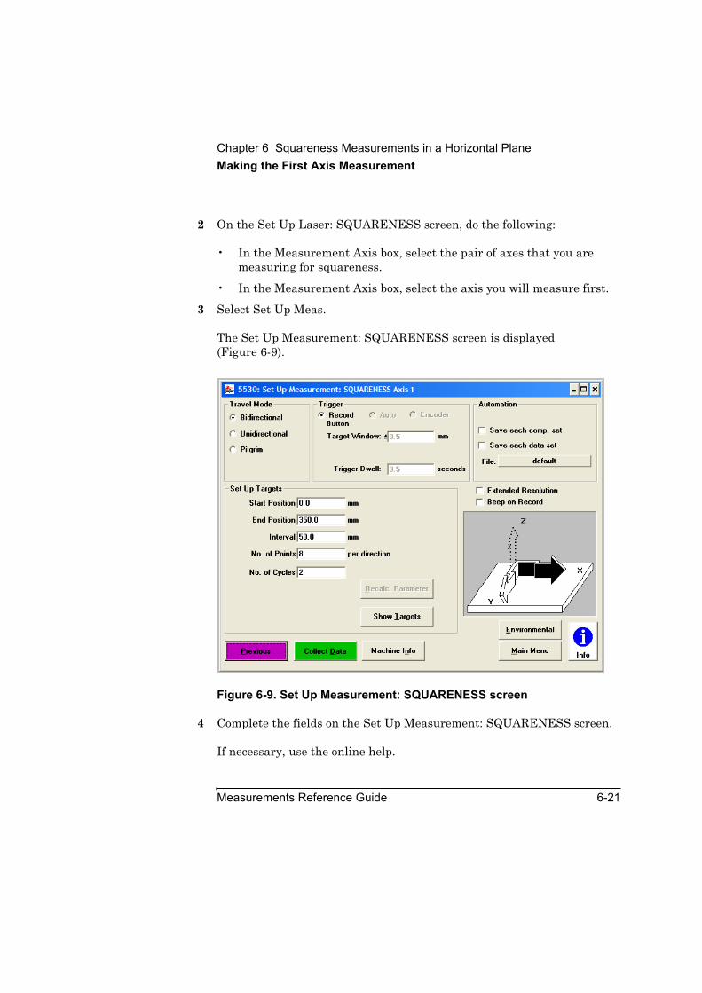
Chapter 6 Squareness Measurements in a Horizontal PlaneMaking the First Axis Measurement
Measurements Reference Guide 6-21
2 On the Set Up Laser: SQUARENESS screen, do the following:
• In the Measurement Axis box, select the pair of axes that you are measuring for squareness.
• In the Measurement Axis box, select the axis you will measure first.
3 Select Set Up Meas.
The Set Up Measurement: SQUARENESS screen is displayed (Figure 6-9).
Figure 6-9. Set Up Measurement: SQUARENESS screen
4 Complete the fields on the Set Up Measurement: SQUARENESS screen.
If necessary, use the online help.
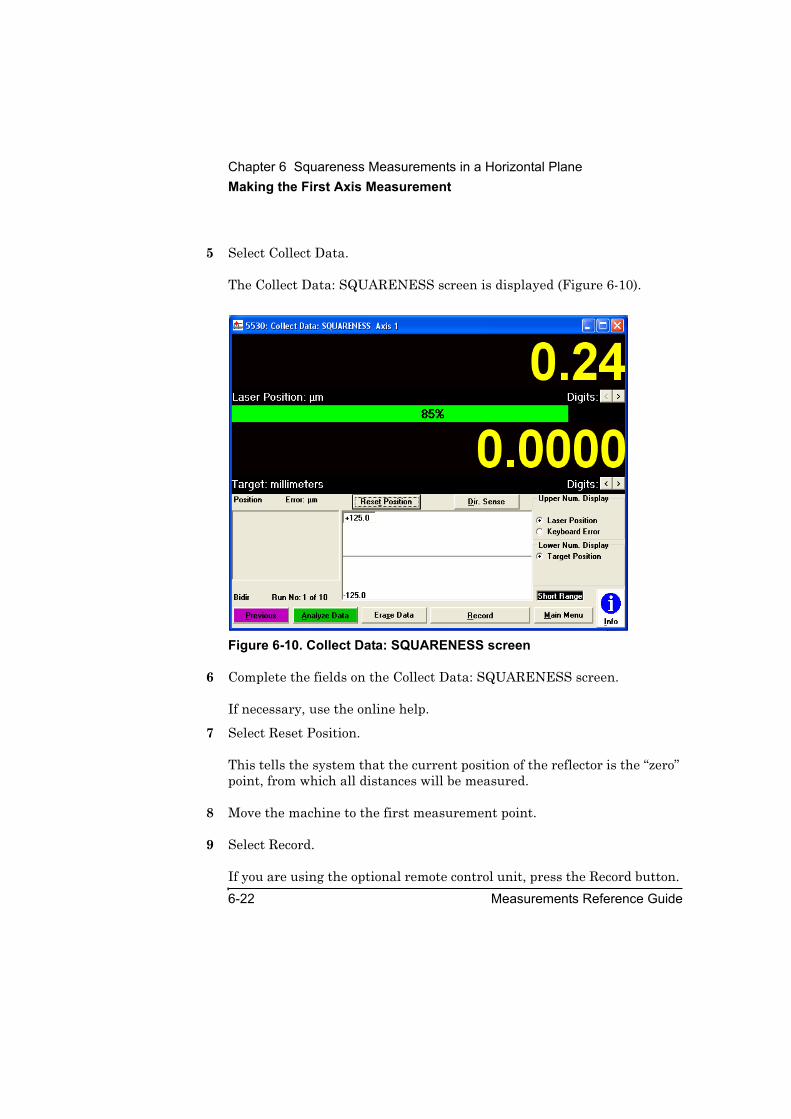
Chapter 6 Squareness Measurements in a Horizontal PlaneMaking the First Axis Measurement
6-22 Measurements Reference Guide
5 Select Collect Data.
The Collect Data: SQUARENESS screen is displayed (Figure 6-10).
Figure 6-10. Collect Data: SQUARENESS screen
6 Complete the fields on the Collect Data: SQUARENESS screen.
If necessary, use the online help.
7 Select Reset Position.
This tells the system that the current position of the reflector is the “zero” point, from which all distances will be measured.
8 Move the machine to the first measurement point.
9 Select Record.
If you are using the optional remote control unit, press the Record button.
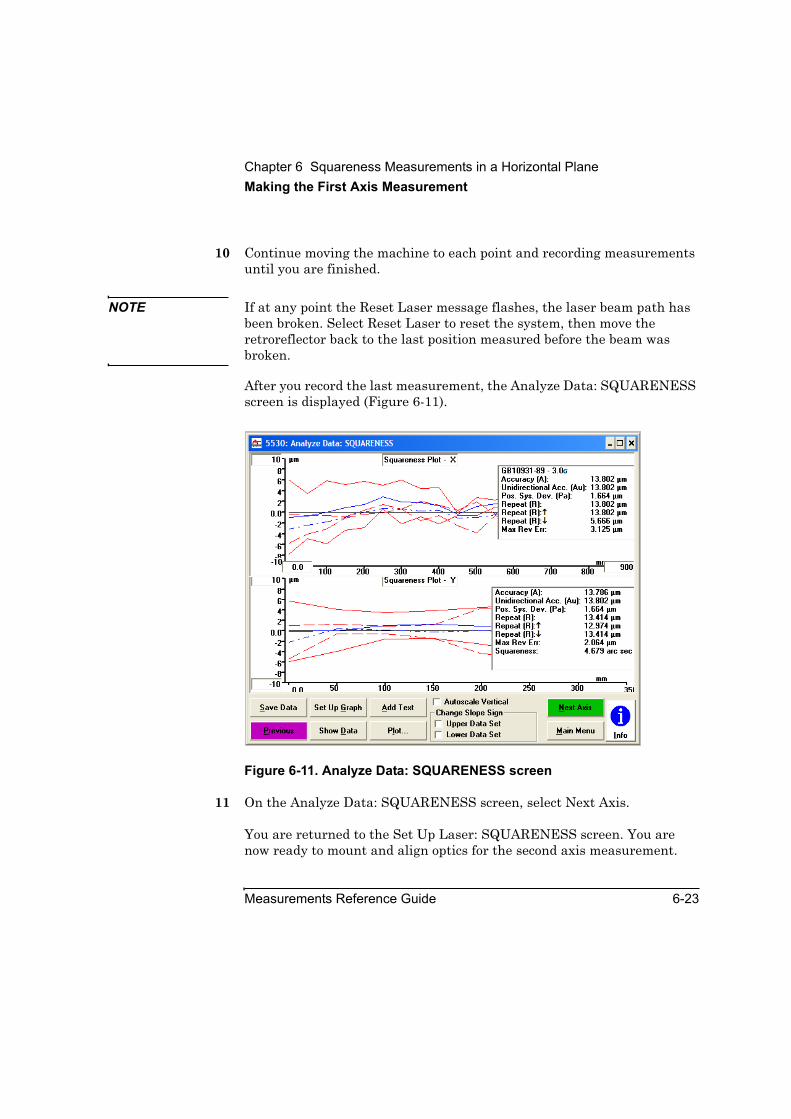
Chapter 6 Squareness Measurements in a Horizontal PlaneMaking the First Axis Measurement
Measurements Reference Guide 6-23
10 Continue moving the machine to each point and recording measurements until you are finished.
NOTE If at any point the Reset Laser message flashes, the laser beam path has been broken. Select Reset Laser to reset the system, then move the retroreflector back to the last position measured before the beam was broken.
After you record the last measurement, the Analyze Data: SQUARENESS screen is displayed (Figure 6-11).
Figure 6-11. Analyze Data: SQUARENESS screen
11 On the Analyze Data: SQUARENESS screen, select Next Axis.
You are returned to the Set Up Laser: SQUARENESS screen. You are now ready to mount and align optics for the second axis measurement.
Chapter 6 Squareness Measurements in a Horizontal PlaneMounting and Aligning Optics for the Second Axis Measurement
6-24 Measurements Reference Guide
Mounting and Aligning Optics for the Second Axis MeasurementUse this procedure to mount and align optics for machines with a horizontal or a vertical spindle.
The second axis measurement is simply a horizontal straightness measurement along the axis on which you previously mounted the reflector.
CAUTION Do not move or adjust the reflector while preparing for or making the second axis measurement. The reflector is the reference for the squareness measurement. If you move the reflector, you lose your reference.
To mount and align optics for the second axis measurement, follow these steps:
1 Remove the optical square and, for machines with a horizontal spindle, the interferometer assembly.
Do not move or adjust the reflector.
2 Move the laser head so it is oriented along the second axis (Figure 6-12 or 6-13).
3 Adjust the laser head so the beam is centered between the reflector’s midpoint notches.
4 Follow the instructions in “Mounting and Aligning Optics for X-Axis or Y-Axis Measurements” in Chapter 5.
CAUTION Do not try to align the laser beam to the travel path of the second axis as instructed at the end of “Mounting and Aligning Optics for X-Axis or Y-Axis Measurements” in Chapter 5. If you do, the software will not be able to calculate squareness between the two axes. Instead, go directly to “Checking the Alignment for Beam Strength for the First Axis Measurement” in this chapter.
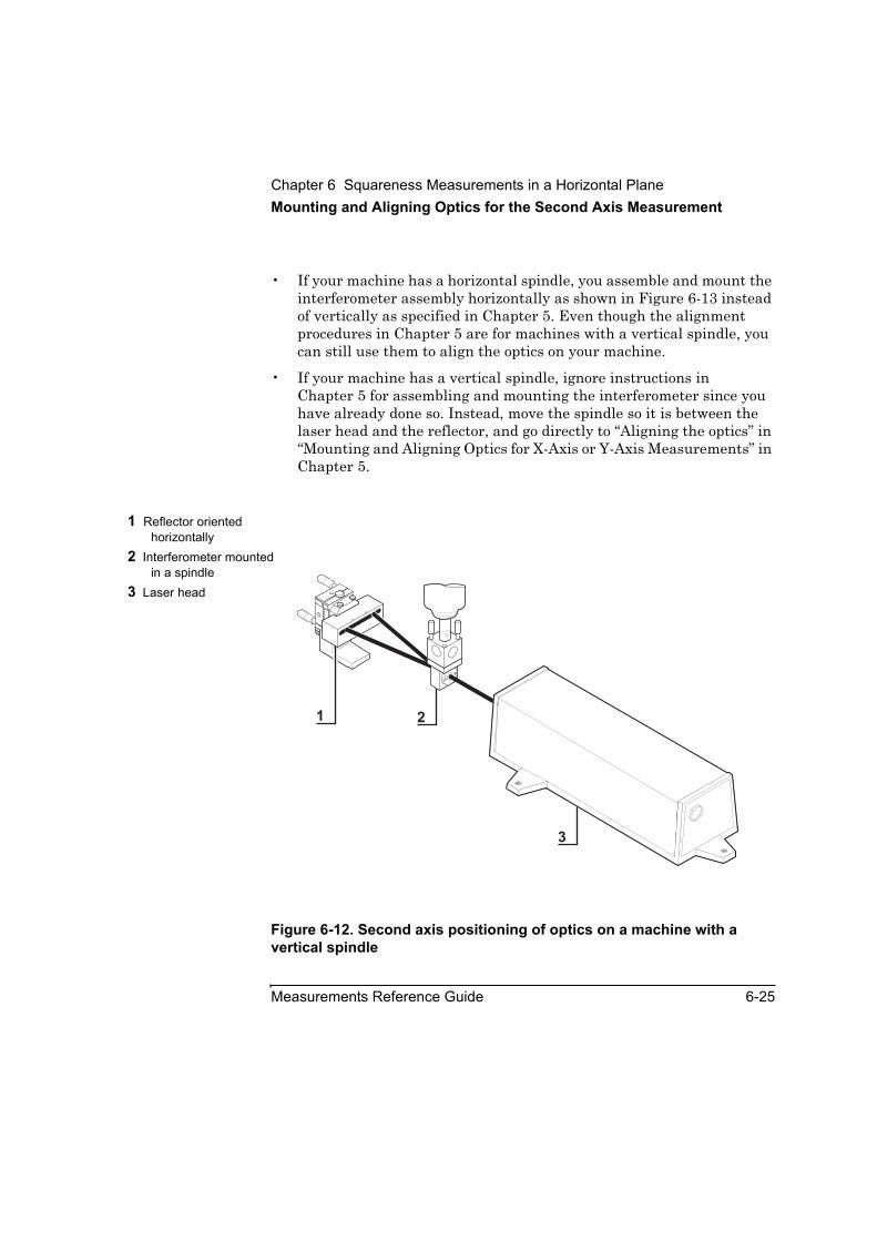
Chapter 6 Squareness Measurements in a Horizontal PlaneMounting and Aligning Optics for the Second Axis Measurement
Measurements Reference Guide 6-25
• If your machine has a horizontal spindle, you assemble and mount the interferometer assembly horizontally as shown in Figure 6-13 instead of vertically as specified in Chapter 5. Even though the alignment procedures in Chapter 5 are for machines with a vertical spindle, you can still use them to align the optics on your machine.
• If your machine has a vertical spindle, ignore instructions in Chapter 5 for assembling and mounting the interferometer since you have already done so. Instead, move the spindle so it is between the laser head and the reflector, and go directly to “Aligning the optics” in “Mounting and Aligning Optics for X-Axis or Y-Axis Measurements” in Chapter 5.
Figure 6-12. Second axis positioning of optics on a machine with a vertical spindle
1 Reflector oriented horizontally
2 Interferometer mounted in a spindle
3 Laser head
1 2
3
1A
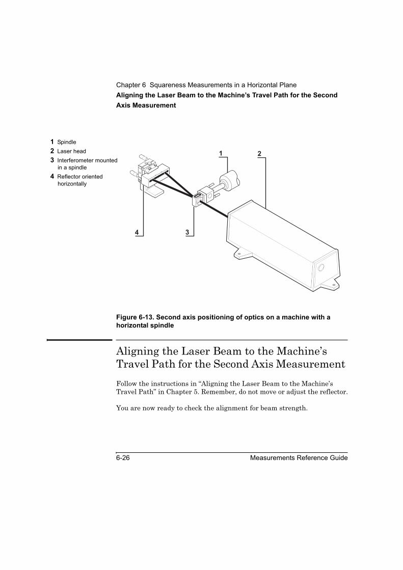
Chapter 6 Squareness Measurements in a Horizontal PlaneAligning the Laser Beam to the Machine’s Travel Path for the Second Axis Measurement
6-26 Measurements Reference Guide
Figure 6-13. Second axis positioning of optics on a machine with a horizontal spindle
Aligning the Laser Beam to the Machine’s Travel Path for the Second Axis Measurement Follow the instructions in “Aligning the Laser Beam to the Machine’s Travel Path” in Chapter 5. Remember, do not move or adjust the reflector.
You are now ready to check the alignment for beam strength.
1 Spindle2 Laser head3 Interferometer mounted
in a spindle4 Reflector oriented
horizontally
1A
4 3
21
Chapter 6 Squareness Measurements in a Horizontal PlaneChecking the Alignment for Beam Strength for the Second Axis Measurement
Measurements Reference Guide 6-27
Checking the Alignment for Beam Strength for the Second Axis MeasurementFollow the instructions in “Checking the Alignment for Beam Strength” in Chapter 5. Remember, do not move or adjust the reflector.
You are now ready to make the second axis measurement.
Making the Second Axis MeasurementTo make the second axis measurement, follow these steps:
1 On the Set Up Laser: SQUARENESS screen, select the second axis you are measuring.
2 Repeats steps 3 through 10 in “Making the First Axis Measurement.”
After you record the last measurement, the Analyze Data: SQUARENESS screen is displayed (Figure 6-11).
Refer to the Agilent 5530 Getting Started Guide and online help for more information about using this screen.
3 On the Analyze Data: SQUARENESS screen, select Save Data to create or update a data file with the measurement data.
Otherwise, you are finished making the measurement.

Chapter 6 Squareness Measurements in a Horizontal PlaneMaking the Second Axis Measurement
6-28 Measurements Reference Guide

7
Squareness Measurements in a Vertical Plane

Chapter 7 Squareness Measurements in a Vertical PlaneIntroduction
7-2 Measurements Reference Guide
IntroductionThis chapter explains how to make squareness measurements in a vertical plane. These measurements allow you to determine if two machine axes are oriented, and move, perpendicular to each other. An example of a machine with two perpendicular axes is a Coordinate Measurement Machine (CMM) with a probe that moves vertically, mounted on a bridge that moves horizontally.
Chapter 6, “Squareness Measurements in a Horizontal Plane,” explains how to determine if two machine axes that are perpendicular to each other in a horizontal plane are oriented, and move, perpendicular to each other.
Before performing the procedures described in this chapter, you must fully understand and know how to perform the procedures presented in the Agilent 5530 Getting Started Guide.
For operating specifications for squareness measurement optics, see Appendix A.
Figure 7-1 shows the required hardware for squareness measurements in a vertical plane.
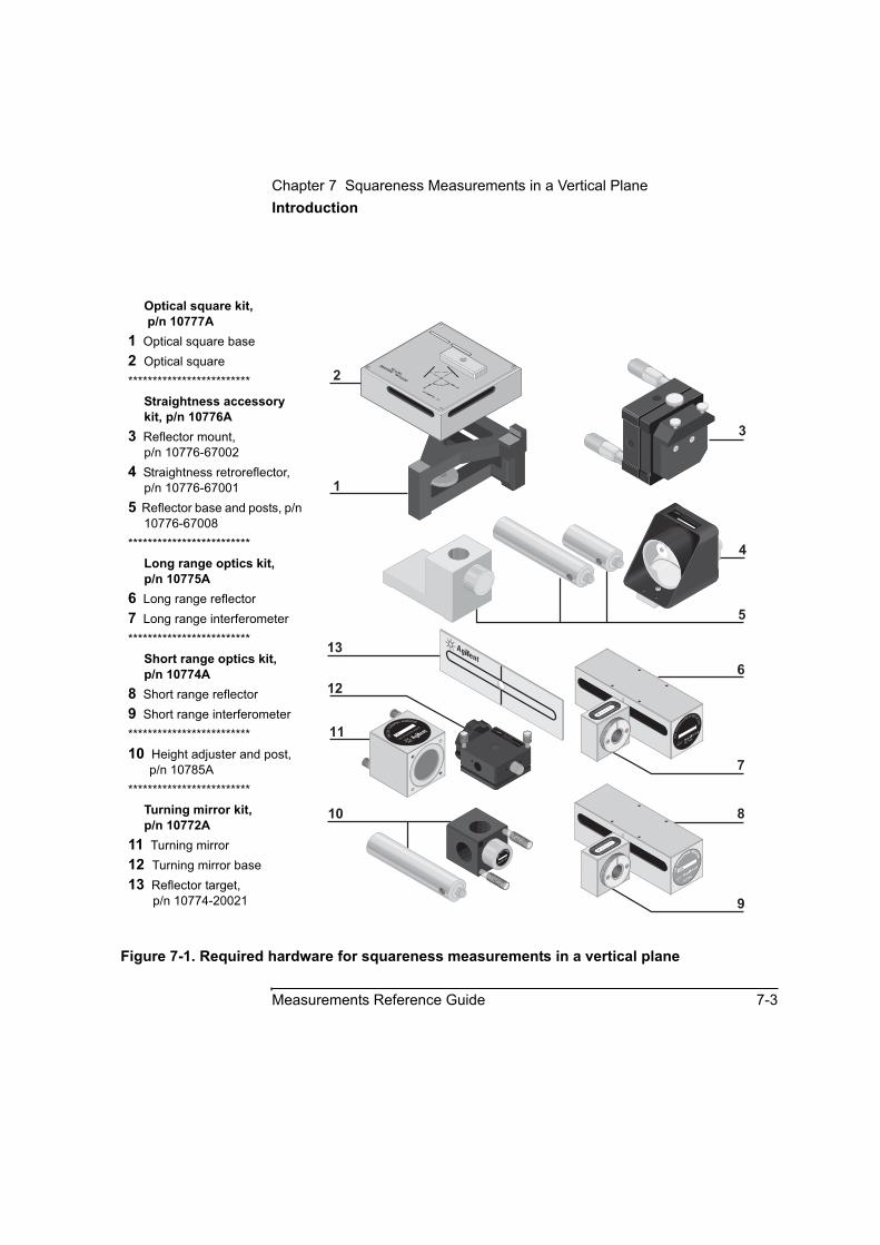
Chapter 7 Squareness Measurements in a Vertical PlaneIntroduction
Measurements Reference Guide 7-3
Figure 7-1. Required hardware for squareness measurements in a vertical plane
Optical square kit, p/n 10777A
1 Optical square base2 Optical square*************************
Straightness accessory kit, p/n 10776A
3 Reflector mount,p/n 10776-67002
4 Straightness retroreflector, p/n 10776-67001
5 Reflector base and posts, p/n 10776-67008
*************************Long range optics kit, p/n 10775A
6 Long range reflector7 Long range interferometer*************************
Short range optics kit, p/n 10774A
8 Short range reflector9 Short range interferometer *************************10 Height adjuster and post,
p/n 10785A*************************
Turning mirror kit, p/n 10772A
11 Turning mirror12 Turning mirror base13 Reflector target,
p/n 10774-20021
6
12
11
10
7
8
9
10772A
TU
RNING MIRROR
1A10772-67002 ASSY
S.R
.STR
A
IGHTN
ESS REFLECTOR
L.R
.STR
AIGHTN
ESS REFLECTOR
2120A
10775A
L.R. STRAIGHTNESS
INTERFEROMETER
1A0 0 9 0 0
S.R. STRAIGHTNESS
INTERFEROMETER
1A0 0 6 0 0
10785A
HEIG
HT ADJUSTER
3
4
5
90
OPTICAL SQUARE
10777A
1
2
13
10776A STRAIGHTNESS ACCESSORY
10776-67001 STR. RETROREFLECTOR
SER. 2216A
10772-67001
Made in U.S.A. of domestic and foreign content
TURNING MIRROR MOUNT ASSEMBLY10774A
Chapter 7 Squareness Measurements in a Vertical PlaneSetting Up for the Measurement
7-4 Measurements Reference Guide
Setting Up for the MeasurementIf you have not already done so, perform the following setup procedures before using the rest of the instructions in this chapter to make a squareness measurement. Refer to the Agilent 5530 Getting Started Guidefor complete instructions when installing and starting the system for the first time.
1 Mount the laser head on the tripod and place the tripod near the target machine.
2 Connect the E1735A USB Axis Module and the E1736A USB Sensor Hub to the USB connectors on your PC. Connect the laser head and remote control unit to the axis module. Connect the sensors to the sensor hub.
3 Plug in and turn on all equipment.
4 Start the Agilent 10747F Metrology Software.
The Metrology Main Menu is displayed.
5 On the Metrology Main Menu, select Other Meas.
The Other Measurements screen is displayed (Figure 7-2).
Alternately, you can open an existing squareness setup file by selecting Recall Data on the Main Menu.
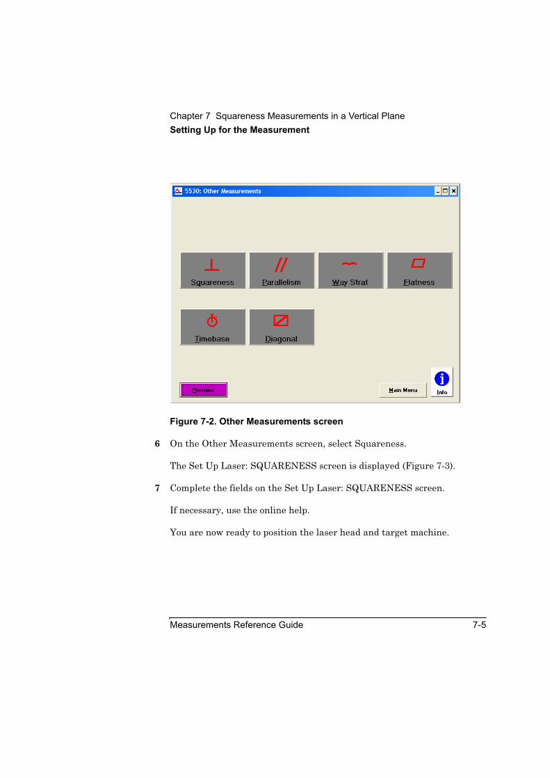
Chapter 7 Squareness Measurements in a Vertical PlaneSetting Up for the Measurement
Measurements Reference Guide 7-5
Figure 7-2. Other Measurements screen
6 On the Other Measurements screen, select Squareness.
The Set Up Laser: SQUARENESS screen is displayed (Figure 7-3).
7 Complete the fields on the Set Up Laser: SQUARENESS screen.
If necessary, use the online help.
You are now ready to position the laser head and target machine.

Chapter 7 Squareness Measurements in a Vertical PlanePositioning the Laser Head and Target Machine
7-6 Measurements Reference Guide
Figure 7-3. Set Up Laser: SQUARENESS screen
Positioning the Laser Head and Target MachineIn squareness measurements, you measure the perpendicularity between two axes. You do this by making a straightness measurement along each of the two axes. The first axis measurement is a straightness measurement along a horizontal axis (Figures 5-3, 5-4, and 5-5). In this measurement, you use a reflector assembly and an interferometer assembly. The second axis measurement is a straightness measurement along the axis perpendicular to the first axis. In this measurement, you use the reflector assembly, an optical square/turning mirror assembly, and an interferometer/retroreflector assembly (Figure 7-9).
Chapter 7 Squareness Measurements in a Vertical Plane
Mounting and Aligning the Optics for the First Axis Measurement
Measurements Reference Guide 7-7
Before you begin to assemble and mount the optics, you must position the laser head and move the moveable part of the target machine to its start position. Follow these steps:
NOTE This chapter uses a machine with a spindle as an example for making squareness measurements. Although your machine may be different, the general procedures described here still apply.
1 Position the laser head for the first axis measurement (Figure 5-3).
2 Adjust the laser head to the approximate height at which you will mount the optics.
3 Determine how to position the optics. See Figure 5-3 for an illustration of the optics setup, and use the following guidelines:
• Mount the combined retroreflector/interferometer where the tool mounts.
• Mount the reflector where the work piece mounts.
You are now ready to mount and align the optics for the first axis measurement.
Mounting and Aligning the Optics for the First Axis Measurement
This section explains how to assemble, mount, and align the optics for the first axis measurement. Follow these steps:
1 Complete steps 1 through 5 in “Mounting and Aligning Optics for X-Axis or Y-Axis Measurements” in Chapter 5.
Keep in mind that the first axis measurement is a measurement in a vertical plane along the X-axis.

Chapter 7 Squareness Measurements in a Vertical PlaneMounting and Aligning the Optics for the First Axis Measurement
7-8 Measurements Reference Guide
2 Attach the optical square to its mount using the attachment screw (Figure 6-6).
3 Place the optical square vertically on the machine close to the reflector assembly. Then line up the midpoint notches on the reflector with the midpoint notches on the optical square.
To line up the notches, adjust the height of the reflector by loosening the large knob on the height adjuster, moving the interferometer up or down, then tightening the knob.
4 Remove the optical square from the machine.
5 Place the reflector assembly on the target machine as shown in Figure 5-3. Make sure the reflector assembly is no closer to the interferometer than:
• 100 mm (4 inches) for short range measurements, and
• 900 mm (36 inches) for long range measurements.
This ensures that the two beams from the interferometer strike the reflector properly. Each of the two beams must strike one of the mirrors in the reflector (Figure 5-3, 5-4, or 5-5).
NOTE Although the mounting assembly provided with the reflector provides considerable mounting flexibility, there may be some situations when you need added flexibility. Figure 2-12 shows how you can use additional hardware to increase flexibility.
6 Complete the steps in “Aligning the optics” in “Mounting and Aligning Optics for X-Axis or Y-Axis Measurements” in Chapter 5.
You are now ready to align the laser beam to the machine’s travel path.

Chapter 7 Squareness Measurements in a Vertical PlaneAligning the Laser Beam to the Machine’s Travel Path for the First Axis Measurement
Measurements Reference Guide 7-9
Aligning the Laser Beam to the Machine’s Travel Path for the First Axis Measurement Follow the instructions in “Aligning the Laser Beam to the Machine’s Travel Path” in Chapter 5. (Although Chapter 5 refers to straightness software screens instead of squareness screens, the instructions still apply.)
You are now ready to check the alignment for beam strength.
Checking the Alignment for Beam Strength for the First Axis MeasurementFollow the instructions in “Checking the Alignment for Beam Strength” in Chapter 5. (Although Chapter 5 refers to straightness software screens instead of squareness screens, the instructions still apply.)
You are now ready to make the first axis measurement.
Making the First Axis MeasurementIn this procedure, you will make manual measurements as you advance the machine’s moveable part. The instructions explain how to make measurements using either the Record button displayed on the screen or the optional remote control unit. See Chapter 1, “Planning Your Measurements,” for a description of other triggering methods.
To make the first axis measurement, follow these steps:
1 Move the moveable optic so it is at the start position.
2 On the Set Up Laser: SQUARENESS screen, do the following:
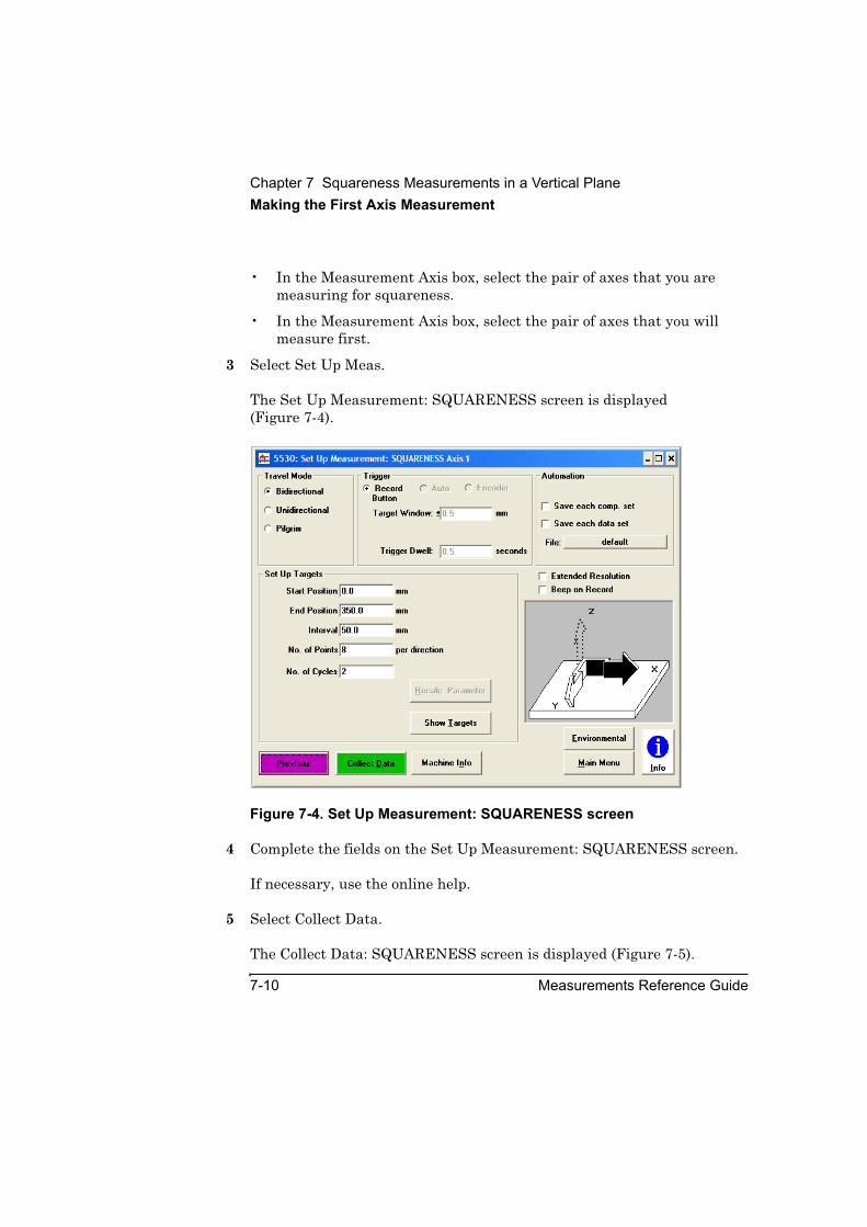
Chapter 7 Squareness Measurements in a Vertical PlaneMaking the First Axis Measurement
7-10 Measurements Reference Guide
• In the Measurement Axis box, select the pair of axes that you are measuring for squareness.
• In the Measurement Axis box, select the pair of axes that you will measure first.
3 Select Set Up Meas.
The Set Up Measurement: SQUARENESS screen is displayed (Figure 7-4).
Figure 7-4. Set Up Measurement: SQUARENESS screen
4 Complete the fields on the Set Up Measurement: SQUARENESS screen.
If necessary, use the online help.
5 Select Collect Data.
The Collect Data: SQUARENESS screen is displayed (Figure 7-5).

Chapter 7 Squareness Measurements in a Vertical PlaneMaking the First Axis Measurement
Measurements Reference Guide 7-11
Figure 7-5. Collect Data: SQUARENESS screen
6 Complete the fields on the Collect Data: SQUARENESS screen.
If necessary, use the online help.
7 Select Reset Position.
This tells the system that the current position of the reflector is the “zero” point, from which all distances will be measured.
8 Move the machine to the first measurement point.
9 Select Record.
If you are using the optional remote control unit, press the Record button.
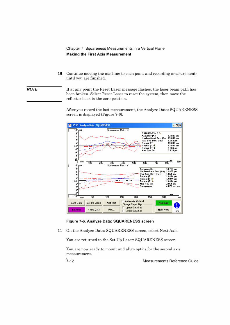
Chapter 7 Squareness Measurements in a Vertical PlaneMaking the First Axis Measurement
7-12 Measurements Reference Guide
10 Continue moving the machine to each point and recording measurements until you are finished.
NOTE If at any point the Reset Laser message flashes, the laser beam path has been broken. Select Reset Laser to reset the system, then move the reflector back to the zero position.
After you record the last measurement, the Analyze Data: SQUARENESS screen is displayed (Figure 7-6).
Figure 7-6. Analyze Data: SQUARENESS screen
11 On the Analyze Data: SQUARENESS screen, select Next Axis.
You are returned to the Set Up Laser: SQUARENESS screen.
You are now ready to mount and align optics for the second axis measurement.

Chapter 7 Squareness Measurements in a Vertical PlaneMounting and Aligning Optics for the Second Axis Measurement
Measurements Reference Guide 7-13
Mounting and Aligning Optics for the Second Axis MeasurementThis section explains how to mount and align the optics for the second axis measurement.
Mounting the opticsTo mount the optics for the second axis measurement, follow these steps:
1 Move the moveable part of the machine to its start position.
2 Remove the current interferometer assembly from the spindle and disassemble the assembly.
3 Attach the turning mirror base to the optical square using the turning mirror attachment screw (Figure 7-7).
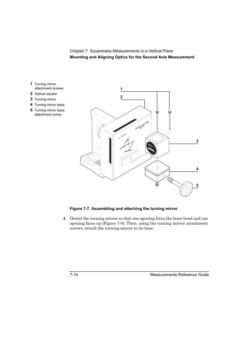
Chapter 7 Squareness Measurements in a Vertical PlaneMounting and Aligning Optics for the Second Axis Measurement
7-14 Measurements Reference Guide
Figure 7-7. Assembling and attaching the turning mirror
4 Orient the turning mirror so that one opening faces the laser head and one opening faces up (Figure 7-8). Then, using the turning mirror attachment screws, attach the turning mirror to its base.
1 Turning mirror attachment screws
2 Optical square3 Turning mirror4 Turning mirror base5 Turning mirror base
attachment screw
90
OPTICAL S
QUARE
10777A
9090
10772ATURNING
M
IRR
OR
1A10772-67002 ASSY
1
2
3
4
5
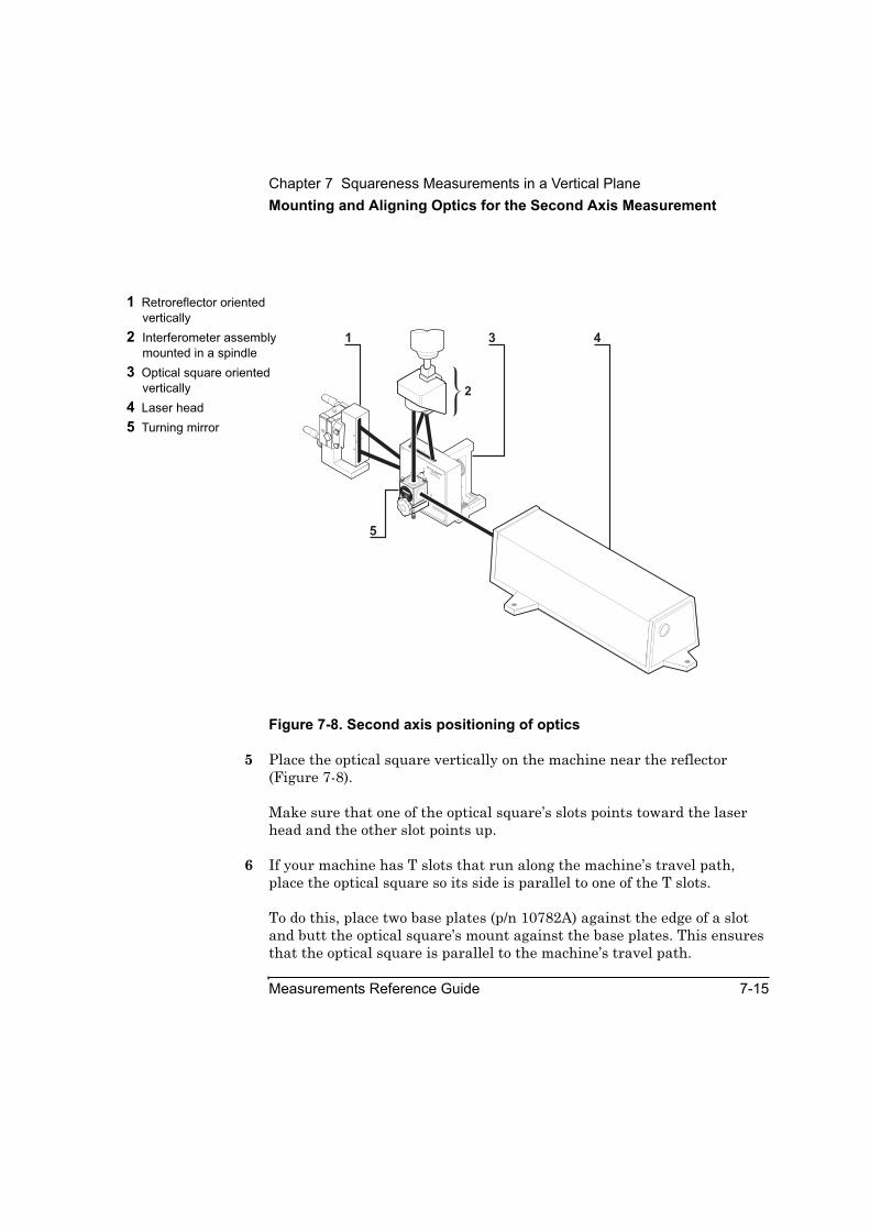
Chapter 7 Squareness Measurements in a Vertical PlaneMounting and Aligning Optics for the Second Axis Measurement
Measurements Reference Guide 7-15
Figure 7-8. Second axis positioning of optics
5 Place the optical square vertically on the machine near the reflector (Figure 7-8).
Make sure that one of the optical square’s slots points toward the laser head and the other slot points up.
6 If your machine has T slots that run along the machine’s travel path, place the optical square so its side is parallel to one of the T slots.
To do this, place two base plates (p/n 10782A) against the edge of a slot and butt the optical square’s mount against the base plates. This ensures that the optical square is parallel to the machine’s travel path.
1 Retroreflector oriented vertically
2 Interferometer assembly mounted in a spindle
3 Optical square oriented vertically
4 Laser head5 Turning mirror
31 4
5
2
OPTICAL SQUARE
10777AHEW
LETT-PACKARD
90
10772ATURNING
M
IRR
OR
HE
W
LE
TT-PACKARD
1A
10772-67002ASSY
1A
Chapter 7 Squareness Measurements in a Vertical PlaneMounting and Aligning Optics for the Second Axis Measurement
7-16 Measurements Reference Guide
7 Attach the interferometer to the retroreflector (Figure 5-13) using the two screws provided. Then, mount the assembly in the spindle.
In the rest of this chapter, this assembly made up of the interferometer and the retroreflector is referred to as the “interferometer assembly.”
NOTE Perform steps 8 through 10 as accurately as possible. They are critical for proper alignment of the optics.
8 Position the interferometer assembly above the optical square as shown in Figure 7-8 so that:
• the interferometer is directly above the turning mirror, and
• the exposed portion of the retroreflector window is directly above the turning mirror
9 Move the interferometer assembly close to the optical square. Then align the center of the interferometer’s window with the midpoint notches on the optical square.
10 Ensure that:
• the top opening in the turning mirror points straight to the interferometer and is not tilted to either side, and
• the top side of the turning mirror is parallel to the top of the optical square
If necessary, adjust the tilt of the turning mirror with the two screws in the bottom of its base (Figure 5-14).
You are now ready to align the optics.
Aligning the opticsTo align the optics, follow these steps:
1 Set the laser head’s upper port to the small aperture by turning the upper aperture control (Figure 2-13).
2 Set the turret ring to STRAIGHT.
Chapter 7 Squareness Measurements in a Vertical PlaneMounting and Aligning Optics for the Second Axis Measurement
Measurements Reference Guide 7-17
3 Visually align the laser head so it is parallel to the machine’s table. Position it so that the beam strikes the center of the turning mirror’s opening.
4 Translate the laser head horizontally so that its beam enters the threaded hole on the side of the optical square facing the laser head.
5 Place a gauge block over the threaded hole and secure it in place using a rubber band (Figure 7-9).
Make sure the rubber band does not cover the area of the gauge block where the laser beam strikes.
The gauge block reflects the beam back to the laser head. The beam appears as a dot on the face of the laser head. If you cannot see the beam, hold a piece of paper in front of the laser head.

Chapter 7 Squareness Measurements in a Vertical PlaneMounting and Aligning Optics for the Second Axis Measurement
7-18 Measurements Reference Guide
Figure 7-9. Gauge block attached to the side of the optical square
6 Turn the optical square left and right until the dot enters the upper port on the laser head.
This makes the optical square perpendicular to the laser beam.
7 If you cannot get the dot to enter the upper port on the laser head, follow these steps:
a. Remove the interferometer assembly from the spindle.
b. Mount a dial indicator in the spindle.
1 Optical square2 Interferometer assembly3 Gauge block4 Laser head
31 4
2
OPTICAL SQ
UARE
10777AHEW
LETT-PACKARD
90
10772ATURNING
M
IRR
OR
HE
W
LE
TT-PACKARD
1A
10772-67002ASSY
1A
Chapter 7 Squareness Measurements in a Vertical PlaneMounting and Aligning Optics for the Second Axis Measurement
Measurements Reference Guide 7-19
c. While moving the table back and forth along the horizontal axis, sweep the side of the optical square.
d. Turn the optical square left or right until it is parallel to the direction of travel.
e. Return the table to its start position.
f. Remove the indicator and remount the interferometer in the spindle.
g. Repeat steps 6 through 8 in the previous section, “Mounting the optics.”
8 Remove the gauge block.
9 Secure the optical square to the machine using a clamp or similar device.
When using a clamp to secure the optical square, cover as much of its base as possible with the clamp so the attachment is secure.
10 Gently tap the reflector assembly to ensure that its mounting is rigid and free of vibration.
If you feel any vibration, tighten all connections in the mounting.
11 Translate the laser head horizontally until the beam strikes the center of the turning mirror.
If you cannot see the beam, hold a piece of paper in front of the turning mirror.
Your goal in steps 12 through 16 is to make the beam from the turning mirror pass through the alignment ring on the retroreflector, through the interferometer, and through the center of the optical square’s top slot.
12 Using the adjusting screws on the turning mirror’s base (Figure 5-14), orient the mirror so that the beam passes through the alignment ring on the retroreflector (Figure 5-15).
13 Remove the interferometer from the retroreflector.
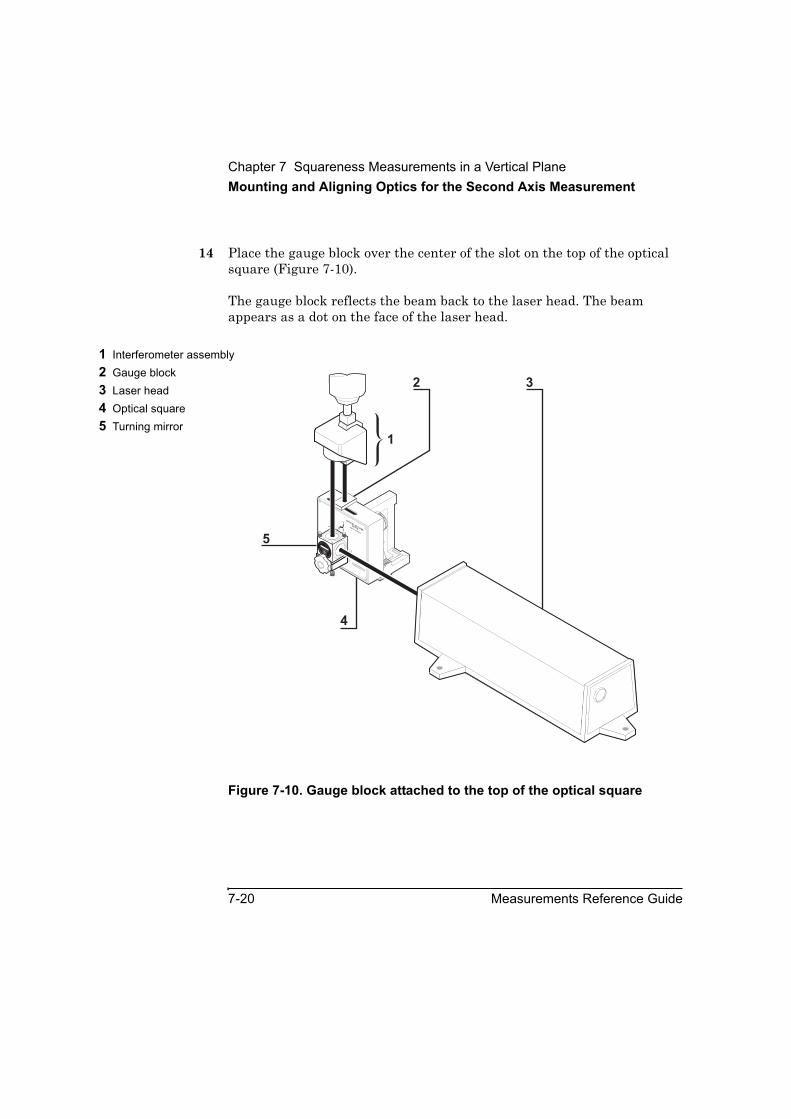
Chapter 7 Squareness Measurements in a Vertical PlaneMounting and Aligning Optics for the Second Axis Measurement
7-20 Measurements Reference Guide
14 Place the gauge block over the center of the slot on the top of the optical square (Figure 7-10).
The gauge block reflects the beam back to the laser head. The beam appears as a dot on the face of the laser head.
Figure 7-10. Gauge block attached to the top of the optical square
1 Interferometer assembly2 Gauge block3 Laser head4 Optical square5 Turning mirror
2 3
1
OPTICAL SQ
UARE
10777AHEW
LETT-PACKARD
90
10772ATURNING
M
IRR
OR
HE
W
LE
TT-PACKARD
1A
10772-67002ASSY
1A
4
5

Chapter 7 Squareness Measurements in a Vertical PlaneMounting and Aligning Optics for the Second Axis Measurement
Measurements Reference Guide 7-21
15 Using the adjusting screws on the turning mirror’s base (Figure 5-14), orient the mirror so that the reflected beam enters the upper port on the laser head.
16 If you cannot get the return beam to enter the upper port, follow these steps:
a. Remove the gauge block.
b. Attach the interferometer to the retroreflector.
c. Rotate the interferometer’s bezel (Figure 5-9) so the scribe line is perpendicular to the optical square’s slot.
d. Translate the laser head horizontally and vertically until the two dots are centered between the midpoint notches on the optical square’s slot (Figure 7-11).
Figure 7-11. Initial position of the dots on the optical square
1 Two dots
90
OPTICAL S
QUARE
10777A
9090
10772ATURNING
M
IRR
OR
1A 10772-67002ASSY
1

Chapter 7 Squareness Measurements in a Vertical PlaneAligning the Laser Beam to the Machine’s Travel Path for the Second Axis Measurement
7-22 Measurements Reference Guide
17 If you cannot get the return beam to enter the upper port using step 16, follow these steps:
a. Repeat steps 8 through 10 in the last section, “Mounting the optics.”
b. Repeat steps 1 through 15 in this section.
When the beam enters the upper port of the laser head, you are ready to align the laser beam to the machine’s travel path.
Aligning the Laser Beam to the Machine’s Travel Path for the Second Axis Measurement Before using the following instructions, make sure that the turret ring on the laser head is set to STRAIGHT and the large opening is in place over the upper aperture.
To align the laser beam to the machine’s travel path, follow these steps:
1 While watching the two dots on the optical square’s surface, move the interferometer away from its start position.
As you move the optic, the two dots in the optical square’s slot separate (Figure 7-12). Your goal is to make sure that (1) they remain in the plane of the midpoint notches on the optical square and (2) both dots remain at an equal distance from the center of the slot.
• If the two dots on the optical square’s surface begin to move out of this pattern, tilt the laser head vertically or rotate it left and right to adjust the dots to their correct position.
• If the beam from the turning mirror moves out of the alignment ring on the retroreflector, translate the laser head vertically or horizontally until the beam reenters the ring.
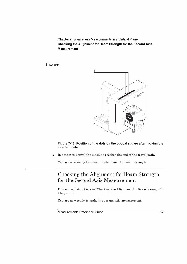
Chapter 7 Squareness Measurements in a Vertical PlaneChecking the Alignment for Beam Strength for the Second Axis Measurement
Measurements Reference Guide 7-23
Figure 7-12. Position of the dots on the optical square after moving the interferometer
2 Repeat step 1 until the machine reaches the end of the travel path.
You are now ready to check the alignment for beam strength.
Checking the Alignment for Beam Strength for the Second Axis Measurement Follow the instructions in “Checking the Alignment for Beam Strength” in Chapter 5.
You are now ready to make the second axis measurement.
1 Two dots
90
OPTICAL S
QUARE
10777A
9090
10772ATURNING
M
IRR
OR
1A10772-67002 ASSY
1

Chapter 7 Squareness Measurements in a Vertical PlaneMaking the Second Axis Measurement
7-24 Measurements Reference Guide
Making the Second Axis MeasurementTo make the second axis measurement, follow these steps:
1 On the Set Up Laser: SQUARENESS screen, select the second axis you are measuring.
2 Repeats steps 3 through 10 in “Making the First Axis Measurement.”
After you record the last measurement, the Analyze Data: SQUARENESS screen is displayed (Figure 7-6).
3 Select Save Data to create or update a data file with the measurement data.
Refer to the Agilent 5530 Getting Started Guide and online help for more information about using the Analyze Data: SQUARENESS screen. Otherwise, you are finished making the measurement.

8
Parallelism Measurements

Chapter 8 Parallelism MeasurementsIntroduction
8-2 Measurements Reference Guide
IntroductionThis chapter explains how to make two types of parallelism measurements: coplanar and spindle. Coplanar parallelism measurements determine if two machine axes move parallel to each other. Spindle parallelism measurements determine if a machine’s spindle (on a lathe, for example) is parallel to the travel path of the machine’s tool.
Before performing the procedures described in this chapter, you must fully understand and know how to perform the procedures presented in the Agilent 5530 Getting Started Guide.
For operating specifications for straightness measurement optics, see Appendix A.
Figure 8-1 shows the required hardware for parallelism measurements.

Chapter 8 Parallelism MeasurementsIntroduction
Measurements Reference Guide 8-3
Figure 8-1. Required hardware for parallelism measurements
1 Optical square (optional), p/n 10777A
************************Straightness accessory kit, p/n 10776A
2 Reflector mount, p/n 10776-67002
3 Straightness retroreflector, p/n 10776-67001
4 Reflector base and posts,p/n 10776-67008
************************Long range optics kit, p/n 10775A
5 Long range reflector6 Long range interferometer************************
Short range optics kit, p/n 10774A
7 Short range reflector8 Short range interferometer ************************9 Height adjuster and post,
p/n 10785A************************
Turning mirror kit, p/n 10772A
10 Turning mirror11 Turning mirror base
10776A STRAIGHTNESS ACCESSORY
10776-67001 STR. RETROREFLECTOR
SER. 2216A
10772A
TU
RNING MIRROR
1A10772-67002 ASSY
10772-67001
Made in U.S.A. of domestic and foreign content
TURNING MIRROR MOUNT ASSEMBLYS
.R.STR
A
IGHTN
ESS REFLECTOR
10774A
L.R
.STR
AIGHTN
ESS REFLECTOR
10775A
L.R. STRAIGHTNESS
INTERFEROMETER
1A0 0 9 0 0
S.R. STRAIGHTNESS
INTERFEROMETER
1A0 0 6 0 0
10785A
HEIG
HT ADJUSTER
290
OPTICAL SQUARE
10777A
3
5
6
7
8
9
10
4
1
11
Chapter 8 Parallelism MeasurementsSetting Up for the Measurement
8-4 Measurements Reference Guide
Setting Up for the MeasurementIf you have not already done so, perform the following setup procedures before using the rest of the instructions in this chapter to make a parallelism measurement. Refer to the Agilent 5530 Getting Started Guidefor complete instructions when installing and starting the system for the first time.
4 Mount the laser head on the tripod and place the tripod near the target machine.
5 Connect the E1735A USB Axis Module and the E1736A USB Sensor Hub to the USB connectors on your PC. Connect the laser head and remote control unit to the axis module. Connect the sensors to the sensor hub.
6 Plug in and turn on all equipment.
7 Start the Agilent 10747F Metrology Software.
The Metrology Main Menu is displayed.
8 On the Metrology Main Menu, select Other Meas.
The Other Measurements screen is displayed (Figure 8-2).
Alternately, you can open an existing parallelism setup file by selecting Recall Data on the Main Menu.
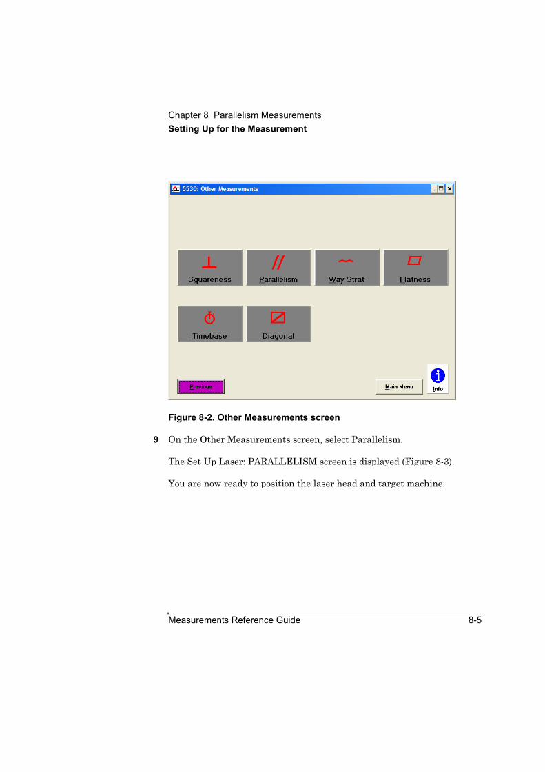
Chapter 8 Parallelism MeasurementsSetting Up for the Measurement
Measurements Reference Guide 8-5
Figure 8-2. Other Measurements screen
9 On the Other Measurements screen, select Parallelism.
The Set Up Laser: PARALLELISM screen is displayed (Figure 8-3).
You are now ready to position the laser head and target machine.
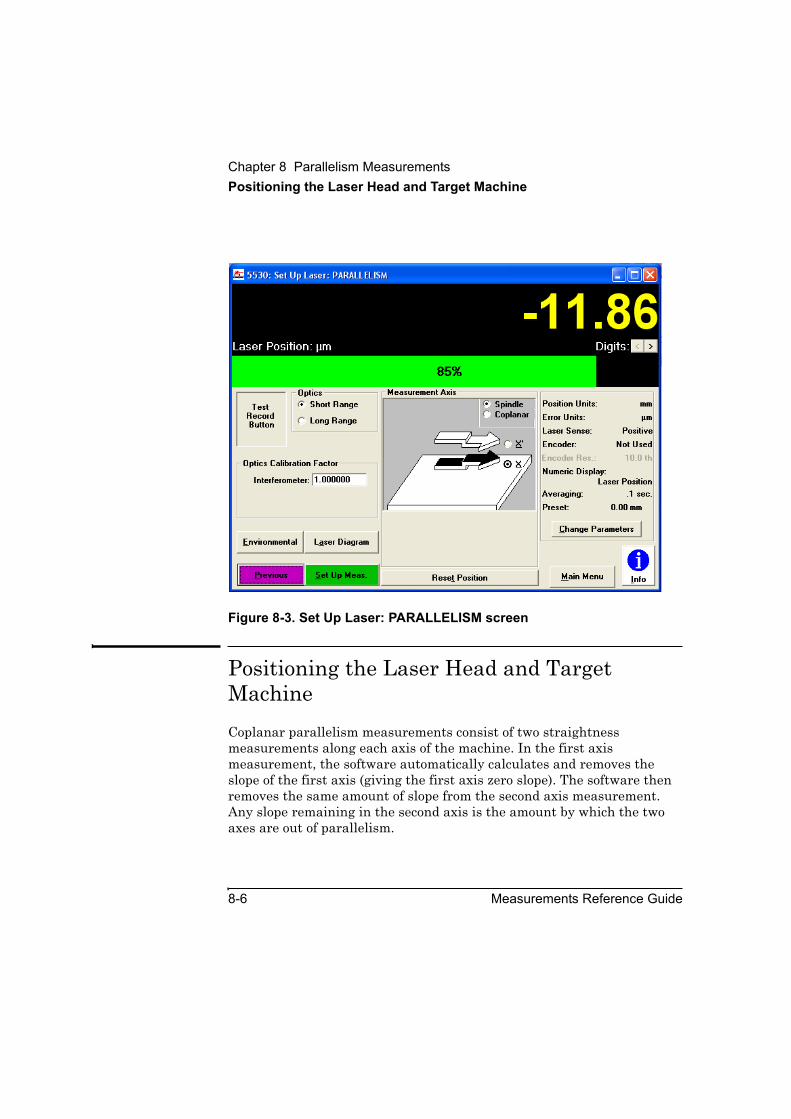
Chapter 8 Parallelism MeasurementsPositioning the Laser Head and Target Machine
8-6 Measurements Reference Guide
Figure 8-3. Set Up Laser: PARALLELISM screen
Positioning the Laser Head and Target MachineCoplanar parallelism measurements consist of two straightness measurements along each axis of the machine. In the first axis measurement, the software automatically calculates and removes the slope of the first axis (giving the first axis zero slope). The software then removes the same amount of slope from the second axis measurement. Any slope remaining in the second axis is the amount by which the two axes are out of parallelism.
Chapter 8 Parallelism MeasurementsPositioning the Laser Head and Target Machine
Measurements Reference Guide 8-7
Spindle parallelism measurements also consist of two measurements; however, both measurements are along the same axis. In one measurement, the optics are oriented to determine how much the spindle is out of vertical alignment with the tool travel path. In the second measurement, the optics are aligned to determine how much the spindle is out of horizontal alignment with the tool travel path. The combination of the two out-of-alignment values is the total out-of-parallelism value.
Before you begin to assemble and mount optics for either type of parallelism measurement, you must position the laser head and move the moveable part of the target machine to its start position. Follow these steps:
NOTE This chapter uses a milling-type machine with a spindle as an example for making coplanar parallelism measurements and a lathe as an example for making spindle parallelism measurements. Although your machine may be different, the general procedures described here still apply.
1 Position the laser head along the axis most suitable for the measurement you want to make (Figure 8-4 or 8-5).
2 Move the moveable part of the machine to its start position.
3 Adjust the laser head to the approximate height at which you will mount the optics.
4 Determine how to position the optics. See Figures 8-4, 8-5, and 8-6 for illustrations of optics setups, and use the following guidelines:
• Mount the interferometer or the combined retroreflector/interferometer assembly where the tool mounts.
• Mount the reflector where the work piece mounts.

Chapter 8 Parallelism MeasurementsPositioning the Laser Head and Target Machine
8-8 Measurements Reference Guide
Figure 8-4. Positioning of optics for coplanar parallelism measurements
A Measurement in a horizontal plane along the Z-axis
B Measurement in a vertical plane along the Z-axis
************************1 Interferometer assembly
oriented horizontally in a spindle
2 Interferometer assembly oriented vertically in a spindle
3 Reflector oriented vertically4 Laser head5 Reflector oriented
horizontally
10776A STRAIGHTNESS ACCESSORY
10776A STRAIGHTNESS ACCESSORY
10776-67001 STR. RETROREFLECTOR
10776-67001 STR. RETROREFLECTOR
H E W L E T T - P A C K A R D
H E W L E T T - P A C K A R D
SER. 2216A
SER. 2216A
4
1
4
5
A
B
2
3

Chapter 8 Parallelism MeasurementsPositioning the Laser Head and Target Machine
Measurements Reference Guide 8-9
Figure 8-5. Positioning of optics for spindle parallelism measurements—solid or heavy tailstock, or no tailstock
1 Reflector mounted horizontally
2 Interferometer mounted where tool mounts
3 Turning mirror4 Laser head placed
perpendicular to spindle
1 2 3
4
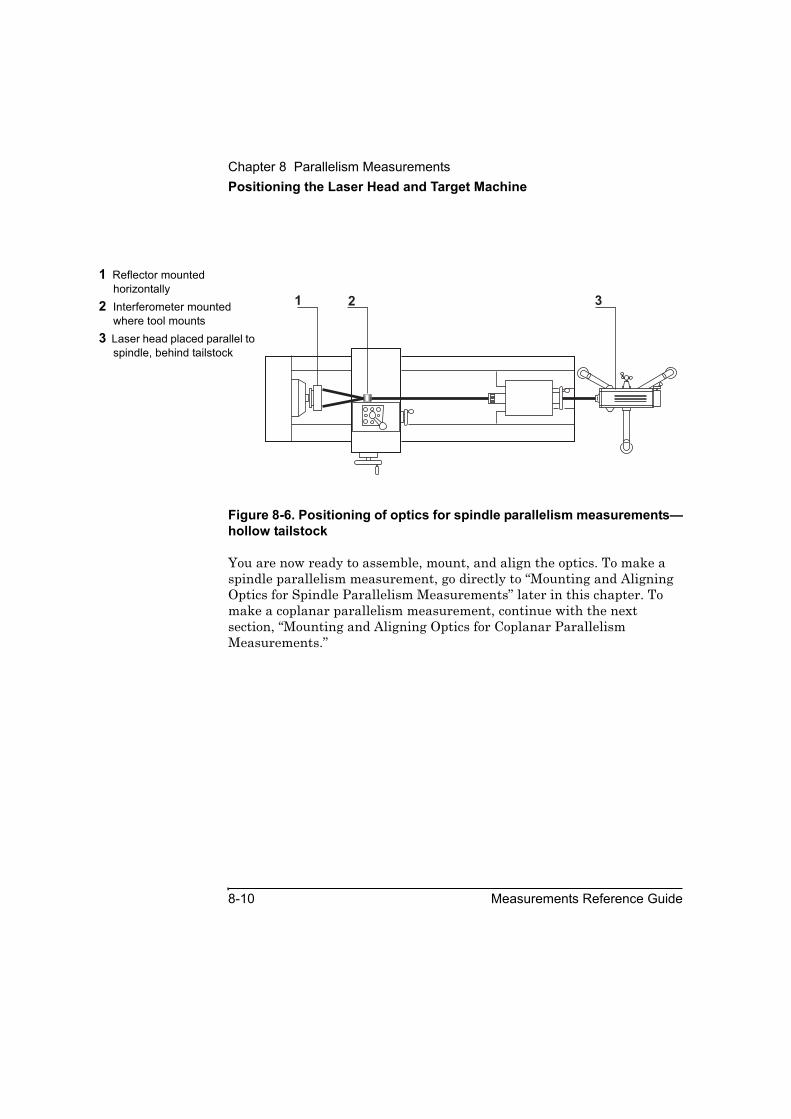
Chapter 8 Parallelism MeasurementsPositioning the Laser Head and Target Machine
8-10 Measurements Reference Guide
Figure 8-6. Positioning of optics for spindle parallelism measurements—hollow tailstock
You are now ready to assemble, mount, and align the optics. To make a spindle parallelism measurement, go directly to “Mounting and Aligning Optics for Spindle Parallelism Measurements” later in this chapter. To make a coplanar parallelism measurement, continue with the next section, “Mounting and Aligning Optics for Coplanar Parallelism Measurements.”
1 Reflector mounted horizontally
2 Interferometer mounted where tool mounts
3 Laser head placed parallel to spindle, behind tailstock
1 2 3
Chapter 8 Parallelism MeasurementsMounting and Aligning Optics for Coplanar Parallelism Measurements
Measurements Reference Guide 8-11
Mounting and Aligning Optics for Coplanar Parallelism MeasurementsDepending on the two axes you want to compare for parallelism and the type of target machine, follow the instructions in one of the following sections in Chapter 5, “Straightness Measurements”:
• “Mounting and Aligning Optics for X-Axis or Y-Axis Measurements”
• “Positioning optics for X-axis and Y-axis measurements”
• “Positioning optics for vertical Z-Axis measurements”
• “Making Vertical Axis Straightness Measurements”
After you mount and align the optics, you are ready to align the laser beam to the machine’s travel path. Go directly to “Aligning the Laser Beam to the Machine’s Travel Path” later in this chapter.
Mounting and Aligning Optics for Spindle Parallelism MeasurementsThis section explains how to assemble, mount, and align the optics necessary for a spindle parallelism first axis measurement.
Mounting the opticsTo mount the optics for spindle parallelism measurements, follow these steps:
1 Place the laser head along the most suitable axis according to the following guidelines:
• If the tailstock is not hollow or is too heavy, place the laser head at the end of the tool’s travel path so the laser head is perpendicular to the spindle (Figure 8-5).

Chapter 8 Parallelism MeasurementsMounting and Aligning Optics for Spindle Parallelism Measurements
8-12 Measurements Reference Guide
• If the tailstock is hollow, place the laser head behind it, parallel to the spindle (Figure 8-6). With this configuration, you direct the laser beam through the tailstock.
• If the tailstock is light, remove it. Then place the laser head at the end of the lathe, parallel to the spindle (Figure 8-6).
CAUTION If the tailstock is heavy enough so that one end of the lathe rises even a small distance after you take it off, your measurement will not be accurate. Therefore, do not remove the tailstock if you think removing it would cause the end of the machine to rise.
• If your lathe does not have a tailstock, place the laser head at the end of the lathe so it is parallel to the spindle (Figure 8-6).
2 Adjust the laser head to the approximate height at which you will mount the optics.
3 Attach the reflector to the reflector mount using the two attachment screws on the top of the reflector mount (Figure 5-8).
Position the reflector so the slot is closest to the top edge.
4 Screw the reflector mounting post into the back of the reflector mount.
Throughout the rest of this chapter, this unit is referred to as the “reflector assembly.”
5 Mount the reflector assembly horizontally or vertically in the spindle (Figure 8-5 or 8-6).
Although Figure 8-5 shows the reflector mounted horizontally, you may mount it horizontally or vertically.
6 Mount the interferometer on the tool post so the beam passes through it (Figure 8-5 or 8-6).
The mounting hardware that you use depends on the type of machine you are calibrating.
Chapter 8 Parallelism MeasurementsMounting and Aligning Optics for Spindle Parallelism Measurements
Measurements Reference Guide 8-13
7 If you did not remove the tailstock, attach the turning mirror to its base and mount it on the tailstock. Follow these steps:
a. Remove the large knob from the turning mirror’s base and screw in a post.
b. Mount the post in the tailstock so the turning mirror’s base is oriented horizontally.
c. Place the turning mirror on the turning mirror base so that one opening faces the laser head and one opening faces the spindle.
d. Attach the turning mirror to its base using the two attachment screws.
You are now ready to align the optics.
Aligning the opticsTo align the optics, follow these steps:
1 If you are using a turning mirror, follow these steps (otherwise, go directly to step 2):
a. Ensure that the side of the turning mirror facing the laser head is not tilted up or down.
b. Adjust the laser head’s position so that the beam is perpendicular to the turning mirror and strikes the center of the turning mirror.
2 Remove the interferometer from the interferometer assembly.
3 Adjust the laser head so that the beam is centered between the midpoint notches on the reflector.
If you are using a turning mirror, you can also center the beam by adjusting the turning mirror’s tilt.
4 Reattach the interferometer to the interferometer assembly.
You are now ready to align the laser beam to the machine’s travel path.
Chapter 8 Parallelism MeasurementsAligning the Laser Beam to the Machine’s Travel Path
8-14 Measurements Reference Guide
Aligning the Laser Beam to the Machine’s Travel PathIf you are making a coplanar parallelism measurement, you must align the laser beam to the travel path of one axis only. It is best to align the laser beam to the longer of the two axes.
If you are making a spindle parallelism measurement, you must align the laser beam to the axis of the tool’s travel path only.
To align the laser beam to the machine’s travel path, follow the instructions in “Aligning the Laser Beam to the Machine’s Travel Path” in Chapter 5. (Although Chapter 5 refers to straightness software screens instead of PARALLELISM screens, the instructions still apply).
You are now ready to check the alignment for beam strength.
Checking the Alignment for Beam StrengthIf you are making a coplanar parallelism measurement, you must check for beam strength along both measurement axes. You can check either axis first.
If you are making a spindle parallelism measurement, you must check for beam strength along the axis of the tool’s travel path only.
To align the laser beam to the machine’s travel path, follow the instructions in “Aligning the Laser Beam to the Machine’s Travel Path” in Chapter 5. (Although Chapter 5 refers to straightness software screens instead of PARALLELISM screens, the instructions still apply).
You are now ready to make parallelism measurements. To make coplanar parallelism measurements, go directly to “Making Coplanar Parallelism Measurements.” To make spindle parallelism measurements, continue with “Making Spindle Parallelism Measurements.”
Chapter 8 Parallelism MeasurementsMaking Spindle Parallelism Measurements
Measurements Reference Guide 8-15
Making Spindle Parallelism MeasurementsIn spindle parallelism measurements, you make four sets of measurements with the reflector oriented as follows:
1 In the first set, the reflector is oriented either horizontally or vertically.
2 In the second set, the reflector is rotated 180 degrees relative to the first set.
3 In the third set, the reflector is rotated 90 degrees relative to the second set.
4 In the fourth set, the reflector is rotated 180 degrees relative to the third set.
It does not matter whether you begin with the horizontal or vertical measurements.
You make manual measurements as you advance the machine’s moveable part. The instructions explain how to make measurements using either the Record button displayed on the screen or the optional remote control unit. See Chapter 1, “Planning Your Measurements,” for a description of other triggering methods.
Making the first set of measurementsTo make the first set of measurements, follow these steps:
1 On the Set Up Laser: PARALLELISM screen, do the following:
• In the Measurement Axis box, select Spindle.
• In the Measurement Axis box, select X.
For instructions on completing the other fields on the screen, use the online help.
2 Select Set Up Meas.
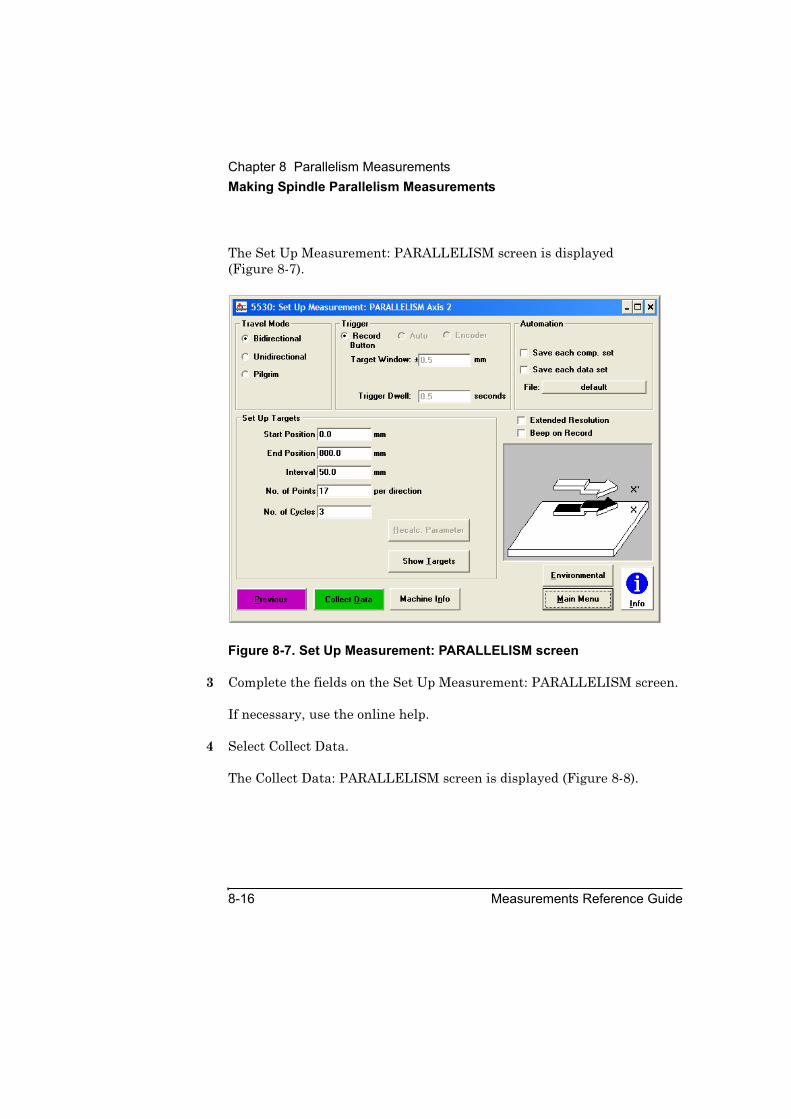
Chapter 8 Parallelism MeasurementsMaking Spindle Parallelism Measurements
8-16 Measurements Reference Guide
The Set Up Measurement: PARALLELISM screen is displayed (Figure 8-7).
Figure 8-7. Set Up Measurement: PARALLELISM screen
3 Complete the fields on the Set Up Measurement: PARALLELISM screen.
If necessary, use the online help.
4 Select Collect Data.
The Collect Data: PARALLELISM screen is displayed (Figure 8-8).

Chapter 8 Parallelism MeasurementsMaking Spindle Parallelism Measurements
Measurements Reference Guide 8-17
Figure 8-8. Collect Data: PARALLELISM screen
5 On the Collect Data: PARALLELISM screen, select Reset Position.
This tells the system that the current position of the reflector is the “zero” point, from which all distances will be measured.
If necessary, use the online help to complete the rest of the fields on this screen.
6 Move the machine’s moveable part to the first measurement point.
7 Select Record.
If you are using the optional remote control unit, press the Record button.
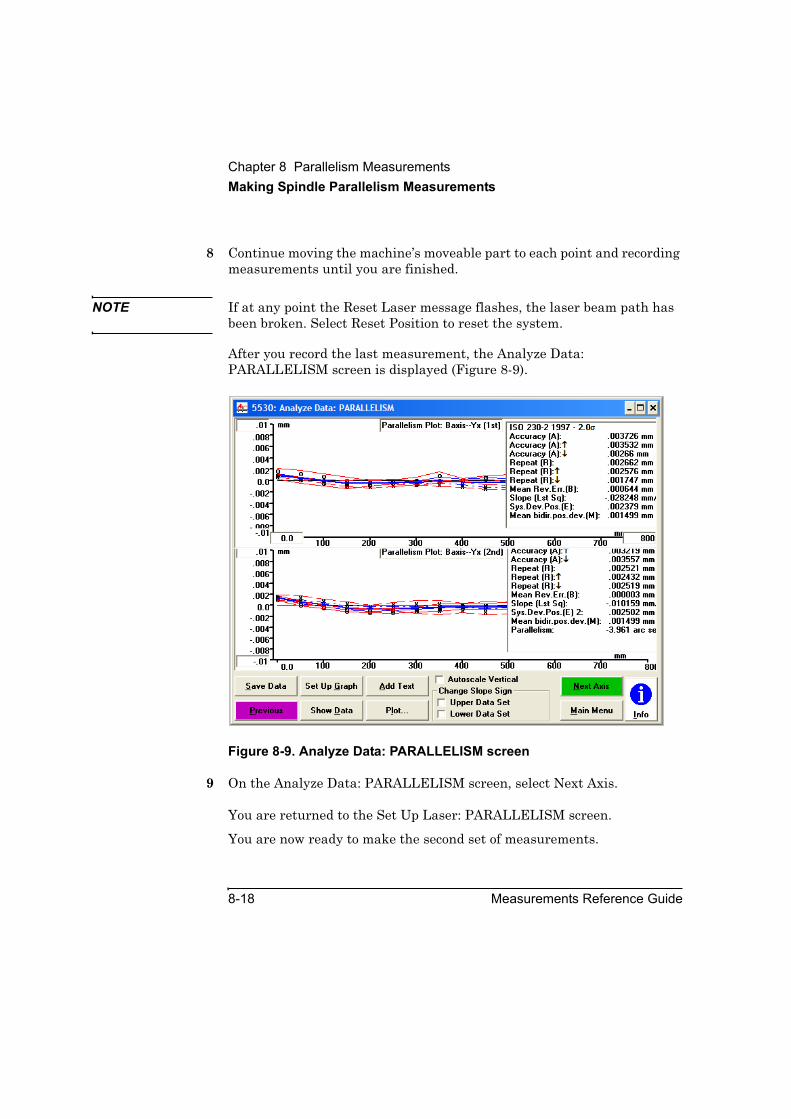
Chapter 8 Parallelism MeasurementsMaking Spindle Parallelism Measurements
8-18 Measurements Reference Guide
8 Continue moving the machine’s moveable part to each point and recording measurements until you are finished.
NOTE If at any point the Reset Laser message flashes, the laser beam path has been broken. Select Reset Position to reset the system.
After you record the last measurement, the Analyze Data: PARALLELISM screen is displayed (Figure 8-9).
Figure 8-9. Analyze Data: PARALLELISM screen
9 On the Analyze Data: PARALLELISM screen, select Next Axis.
You are returned to the Set Up Laser: PARALLELISM screen.
You are now ready to make the second set of measurements.

Chapter 8 Parallelism MeasurementsMaking Spindle Parallelism Measurements
Measurements Reference Guide 8-19
Making the second set of measurementsTo make the second set of measurements, follow these steps:
1 Rotate the reflector 180 degrees.
2 Select X' on the Set Up Laser: PARALLELISM screen.
3 Repeat steps 2 through 8 in “Making the first set of measurements.”
A pop-up window is displayed. The parallelism measurement value is displayed in the Parallelism field.
4 Write down the number displayed in the Parallelism field.
5 Select Previous.
You are now ready to make the third set of measurements.
Making the third set of measurementsTo make the third set of measurements, follow these steps:
1 Rotate the reflector 90 degrees.
2 On the Analyze Data: PARALLELISM screen, select Main Menu.
The Metrology Main Menu is displayed.
3 On the Metrology Main Menu, select Other Meas, then select Parallelism.
The Set Up Laser: PARALLELISM screen is displayed (Figure 8-3).
4 Repeat steps 1 through 9 in “Making the first set of measurements.”
5 On the Analyze Data: PARALLELISM screen, select Next Axis.
You are now ready to make the fourth set of measurements.

Chapter 8 Parallelism MeasurementsMaking Coplanar Parallelism Measurements
8-20 Measurements Reference Guide
Making the fourth set of measurementsTo make the fourth set of measurements, repeat the steps in “Making the second set of measurements.” After you make the fourth set of measurements, the Analyze Data: PARALLELISM screen is displayed.
You are now ready to calculate the total out-of-parallelism value.
Calculating the total out-of-parallelism valueTo calculate the total out of parallelism value, follow these steps:
1 Square the parallelism value that you obtained from the first set of measurements.
2 Square the parallelism value that you obtained from the second set of measurements.
3 Add the two figures together.
4 Calculate the square root of the sum.
5 On the Analyze Data: PARALLELISM screen, Select Save Data to create or update a data file with the measurement data.
Refer to the Agilent 5530 Getting Started Guide and online help for more information about using the Analyze Data: PARALLELISM screen. Otherwise you are finished making the measurement.
Making Coplanar Parallelism MeasurementsIn coplanar parallelism measurements, you can measure either axis first. You make manual measurements as you advance the machine’s moveable part. The instructions explain how to make measurements using either the Record button displayed on the screen or the optional remote control unit. See Chapter 1, “Planning Your Measurements,” for a description of other triggering methods.
Chapter 8 Parallelism MeasurementsMaking Coplanar Parallelism Measurements
Measurements Reference Guide 8-21
Making the first axis measurementTo make the first axis measurement, follow these steps:
1 Return each of the two moveable parts to its start position.
2 On the Set Up Laser: PARALLELISM screen, do the following:
• In the Measurement Axis box, select Coplanar.
• In the Measurement Axis box, select X.
“X” tells the system this is the first axis measurement.
For instructions on completing the other fields on the screen, use the online help.
3 On the Set Up Laser: PARALLELISM screen, select Set Up Meas.
The Set Up Measurement: PARALLELISM screen is displayed (Figure 8-7).
4 Complete the fields on the Set Up Measurement: PARALLELISM screen.
If necessary, use the online help.
5 Select Collect Data.
The Collect Data: PARALLELISM screen is displayed (Figure 8-8).
6 On the Collect Data: PARALLELISM screen, select Reset Position.
This tells the system that the current position of the reflector is the “zero” point, from which all distances will be measured.
For instructions on completing the other fields on the screen, use the online help.
7 Move the machine’s moveable part until the machine has reached the first measurement position.
8 Select Record.
If you are using the optional remote control unit, press the Record button.

Chapter 8 Parallelism MeasurementsMaking Coplanar Parallelism Measurements
8-22 Measurements Reference Guide
9 Continue moving the machine’s moveable part to each point and recording measurements until you are finished.
NOTE If at any point the Reset Laser message flashes, the laser beam path has been broken. Move the reflector back to the zero position then select Reset Position to reset the system.
After you record the last measurement, the Analyze Data: PARALLELISM screen is displayed (Figure 8-9).
10 On the Analyze Data: PARALLELISM screen, select Next Axis.
You are returned to the Set Up Laser: PARALLELISM screen.
You are now ready to make the second axis measurement.
Making the second axis measurement To make the second axis measurement, follow these steps:
1 Move the first axis moveable part to its start position.
2 On the Set Up Laser: PARALLELISM screen, do the following:
• In the Measurement Axis box, select Coplanar.
• In the Measurement Axis box, select W.
“W” tells the system this is the second axis measurement.
3 Repeat steps 3 through 8 in the last section, “Making the first axis measurement.”
Move the second axis moveable part. A pop-up window is displayed. The parallelism value for the two axes is displayed in the Parallelism field.
4 Select Save Data to create or update a data file with the measurement data. Refer to the Agilent 5530 Getting Started Guide and online help for more information about using the Analyze Data: PARALLELISM screen. Otherwise, you are finished making the measurement.

9
Flatness Measurements
Chapter 9 Flatness MeasurementsIntroduction
9-2 Measurements Reference Guide
IntroductionThis chapter explains how to make flatness measurements at multiple points along measurement lines of a grid on a surface plate. You make flatness measurements to check the flatness of a surface plate or similar object. You would do this, for example, to ensure that the object meets flatness specifications or requirements.
Before performing the procedures described in this chapter, you should fully understand and know how to perform the procedures presented in the Agilent 5530 Getting Started Guide.
Since you use the angular interferometer and reflector to make flatness measurements, see angular measurement specifications for these optics in Appendix A. See the flatness measurement specifications for flatness specifications.
Figure 9-1 shows the required hardware for flatness measurements.

Chapter 9 Flatness MeasurementsIntroduction
Measurements Reference Guide 9-3
Figure 9-1. Required hardware for flatness measurements
1 Foot spacing kit,p/n 10759A
2 Angular interferometer, p/n 10770A
3 Angular reflector,p/n 10771A
4 Two alignment targets, p/n 10767-67001
5 Two flatness mirrors with base, p/n 10773A
1
3
5
4
10771A
ANGU
LAR REFLECTOR
1 A 0 1 0 1
10770AAN
GULAR
INTERFEROMETER
1 A 0 1 0 1
2
1077
0AAN
GULAR INTERFEROMETER
1 A 0 1 0 1

Chapter 9 Flatness MeasurementsSetting Up for the Measurement
9-4 Measurements Reference Guide
Setting Up for the MeasurementIf you have not already done so, perform the following setup procedures before using the rest of the instructions in this chapter to make a flatness measurement. Refer to the Agilent 5530 Getting Started Guide for complete instructions when installing and starting the system for the first time.
1 Mount the laser head on the tripod and place the tripod near the target machine.
2 Connect the E1735A USB Axis Module and the E1736A USB Sensor Hub to the USB connectors on your PC. Connect the laser head and remote control unit to the axis module. Connect the sensors to the sensor hub.
3 Plug in and turn on all equipment.
4 Start the Agilent 10747F Metrology Software.
The Metrology Main Menu is displayed.
5 On the Metrology Main Menu, select Other Meas.
The Other Measurements screen (Figure 9-2) is displayed.
Alternatively, you can open an existing flatness measurement setup file by selecting Recall Data on the Main Menu, then selecting the file.
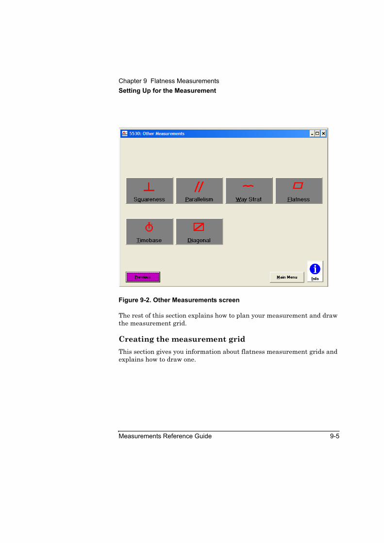
Chapter 9 Flatness MeasurementsSetting Up for the Measurement
Measurements Reference Guide 9-5
Figure 9-2. Other Measurements screen
The rest of this section explains how to plan your measurement and draw the measurement grid.
Creating the measurement gridThis section gives you information about flatness measurement grids and explains how to draw one.
Chapter 9 Flatness MeasurementsSetting Up for the Measurement
9-6 Measurements Reference Guide
Planning your measurement gridTo measure the flatness of a surface plate, you must draw the lines along which you will make measurements on the surface plate. The border of the grid is determined by whether or not you can align the laser head with each of the measurement lines by moving the laser head around the surface plate. Usually, the floor area around the surface plate is clear enough to allow you to move the laser head from line to line around the surface plate in order to make measurements.
Sometimes, however, the surface plate is in a corner or has equipment by it that prevents you from moving the laser head around all sides of the surface plate. If this is the case, first measure the axes along which you can align the laser beam. Then, line up the laser head with one side of the surface plate and use flatness mirrors to direct the laser beam along each remaining measurement axis.
NOTE Measurements using flatness mirrors are more complicated and take longer to perform than measurements without flatness mirrors. Use flatness mirrors only if it is necessary.
After you have determined whether you will use flatness mirrors, you are ready to draw the measurement grid.
Determining grid border requirementsIn order to properly position the optics on the surface plate, you must leave a border between the measurement grid perimeter lines and the edge of the surface plate.
If you can move the laser head to each measurement line, leave at least a 51 to 76 mm (2 to 3 inch) border. The border allows sufficient room for you to place optics for measurements along the perimeter lines. Figure 9-3 shows an example of a measurement grid with 76 mm (3 inch) borders.

Chapter 9 Flatness MeasurementsSetting Up for the Measurement
Measurements Reference Guide 9-7
Choosing a foot spacerBefore you draw the measurement lines, choose a foot spacer. You use the foot spacers to mark the measurement points, called “stations,” on the lines as you are drawing the grid. The foot spacer kit includes three foot spacers: 51 mm (2 inch), 102 mm (4 inch), and 152 mm (6 inch). These sizes are actually the distances between the scribe lines on the leading and trailing feet of the foot spacers rather than the overall length of the foot spacers.
When choosing a foot spacer, remember that the smaller the foot spacer, the longer it will take you to perform the entire measurement process, but the better your measurement resolution will be.
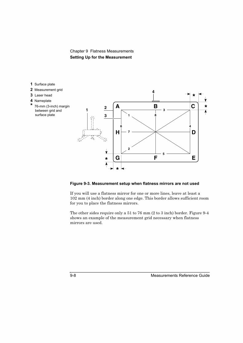
Chapter 9 Flatness MeasurementsSetting Up for the Measurement
9-8 Measurements Reference Guide
Figure 9-3. Measurement setup when flatness mirrors are not used
If you will use a flatness mirror for one or more lines, leave at least a 102 mm (4 inch) border along one edge. This border allows sufficient room for you to place the flatness mirrors.
The other sides require only a 51 to 76 mm (2 to 3 inch) border. Figure 9-4 shows an example of the measurement grid necessary when flatness mirrors are used.
1 Surface plate2 Measurement grid3 Laser head4 Nameplate* 76-mm (3-inch) margin
between grid and surface plate
**
**A B C
G F E
H D
8
7
1
2
2
33
4
5
6
1
4
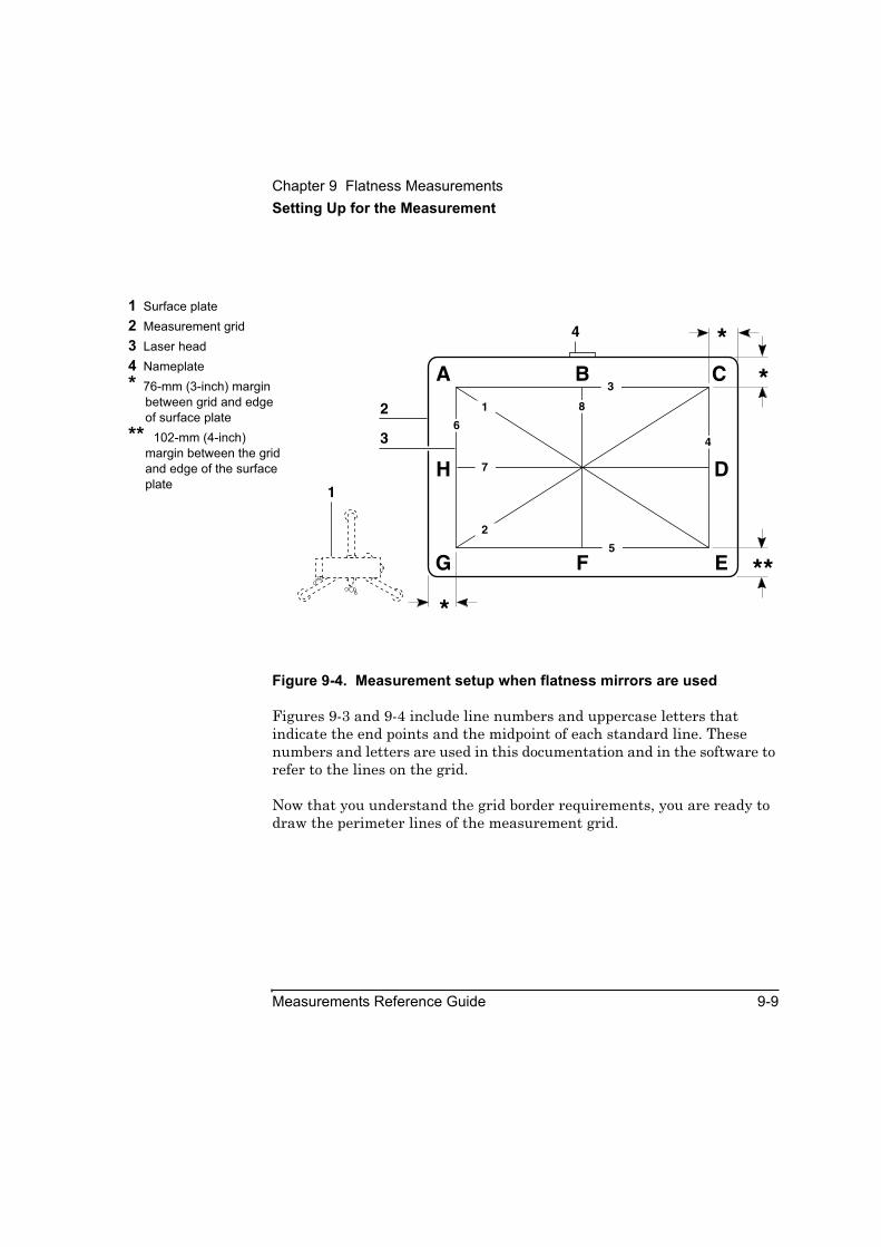
Chapter 9 Flatness MeasurementsSetting Up for the Measurement
Measurements Reference Guide 9-9
Figure 9-4. Measurement setup when flatness mirrors are used
Figures 9-3 and 9-4 include line numbers and uppercase letters that indicate the end points and the midpoint of each standard line. These numbers and letters are used in this documentation and in the software to refer to the lines on the grid.
Now that you understand the grid border requirements, you are ready to draw the perimeter lines of the measurement grid.
1 Surface plate2 Measurement grid3 Laser head4 Nameplate* 76-mm (3-inch) margin
between grid and edge of surface plate
** 102-mm (4-inch) margin between the grid and edge of the surface plate
***
**A B C
G F E
H D
8
3
6
7
5
1
2
2
3
1
4
4

Chapter 9 Flatness MeasurementsSetting Up for the Measurement
9-10 Measurements Reference Guide
Drawing the perimeter lines of the measurement gridAlthough you have already approximated the border for your measurement, in this section you draw the lines that define the actual border for your measurement (lines 3 through 6). To correctly draw the measurement grid, you must first draw the perimeter lines of the measurement grid. To do so, refer to Figures 9-3 and 9-4, and follow these steps:
1 Use the foot spacer to mark stations on the straightedge.
You can then use the straightedge to mark these stations on the surface plate. Remember, the size of the interval is the distance between the scribe lines on the foot spacer you chose.
2 Using a straightedge and a pencil or chalk, draw a perimeter line on the side closest to the surface plate's nameplate (Line 3).
Be sure to leave the correct size border between the line and the edges of the surface plate.
3 Mark the foot spacer stations on the line by following these steps:
a. Mark the midpoint of Line 3 (Point B).
b. Align the center of the straightedge with this midpoint.
c. Starting at the midpoint, mark your measurement stations in both directions on the line.
Remember, the size of the intervals is the distance between the scribe lines on the foot spacer you chose.
Do not mark within your border. If marking a station extends the line into the border between the measurement grid and the edge of the surface plate, the previous station is now the end of the line (points A and C).
Note the number of stations marked.
d. Mark the end points of Line 3.

Chapter 9 Flatness MeasurementsSetting Up for the Measurement
Measurements Reference Guide 9-11
e. Write down the length of the line in millimeters or inches. You enter this length in the Set Up FLATNESS screen.
The length of the line is the number of stations multiplied by the distance between stations.
4 Starting at the end (Point C) of the first perimeter line (Line 3), draw a second line perpendicular to the first line (Line 4).
Be sure to leave the correct size border between the end of the line and the edge of the surface plate.
5 Mark stations on Line 4 by following these steps:
a. Starting at the end of the line that connects with Line 3 (Point C), mark your measurement stations along this line. Be sure to mark an even number of stations.
The last station you mark is now the end of Line 4 (Point E).
Note the number of stations marked.
b. Mark the midpoint of the line (Point D).
6 Draw the third perimeter line (Line 6) the same length as and parallel to Line 4.
This line must be perpendicular to the first line.
7 Using Line 4 as a guide, mark stations at the same locations on this line.
Write down the length of the line in millimeters or inches. You enter this length in the Set Up FLATNESS screen later.
The length of the line is the number of stations multiplied by the distance between stations.
8 Draw Line 5 by connecting the ends of Lines 4 and 6.
9 Using Line 3 as a guide, mark stations at the same locations on this line.
You should have a rectangle with pairs of equal sides and an equal number of stations on opposing sides. If you do not, recheck your work.

Chapter 9 Flatness MeasurementsSetting Up for the Measurement
9-12 Measurements Reference Guide
You are now ready to draw the internal measurement lines.
Drawing the internal measurement linesTo draw the internal measurement lines, follow these steps:
1 Draw diagonal lines to connect opposite corners of the grid (AE and GC in Figure 9-3 or 9-4).
2 Mark stations on each of the diagonals, following these guidelines:
• Mark stations outward from the intersection point of the two diagonals.
• Both halves of a diagonal must have the same number of stations.
• If you cannot mark a whole number of stations on the diagonal, you can either stop short of or continue past the end of the diagonal. The software indicates the number of stations you should mark on the diagonal.
• You must have the same number of stations on each diagonal. If not, all corners of the measurement grid may not be 90 degrees; recheck your work.
3 Draw lines to connect the midpoints of opposite sides of the grid (lines 7 and 8 in Figure 9-3 or 9-4).
4 Mark stations on Lines 7 and 8.
The number of stations on Lines 7 and 8 must equal the number of stations on the perimeter lines that parallel them.
If not, recheck your work.
You are now ready to assemble and mount the optics.

Chapter 9 Flatness MeasurementsAssembling and Mounting the Optics
Measurements Reference Guide 9-13
Assembling and Mounting the OpticsThis section explains how to assemble the optics and mount them on the surface plate.
NOTE The foot spacers in the foot spacer kit have three feet. One side of each foot spacer has two feet, the opposite side has one foot centered between the other two feet. In the rest of this chapter, these two feet are referred to as the “measurement line feet.”
Assembling the opticsTo assemble the optics, follow these steps:
1 Using the screws provided, attach the angular reflector to the foot spacer you chose (Figure 9-5). Follow these guidelines.
Attach the reflector to the foot spacer so that after you place the reflector and foot spacer on the surface plate:
• The side of the reflector with two openings faces the laser beam.
• The measurement line feet are centered over the measurement line (Figure 9-6).
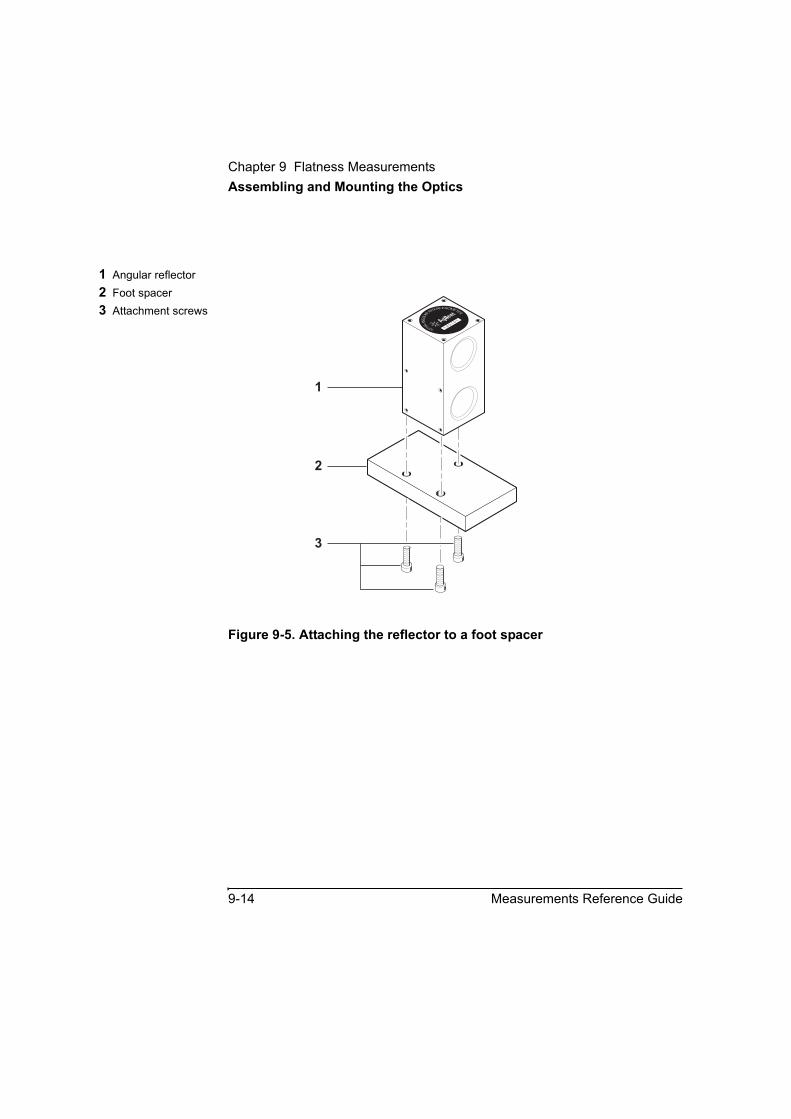
Chapter 9 Flatness MeasurementsAssembling and Mounting the Optics
9-14 Measurements Reference Guide
Figure 9-5. Attaching the reflector to a foot spacer
1 Angular reflector2 Foot spacer3 Attachment screws
1
2
10770AAN
GULAR
INTERFEROMETER
1 A 0 1 0 1
3

Chapter 9 Flatness MeasurementsAssembling and Mounting the Optics
Measurements Reference Guide 9-15
Figure 9-6. Centering the leading and trailing feet over the measurement line
2 Attach the angular interferometer to a flatness mirror base (Figure 9-7). Follow these guidelines.
If you are not using flatness mirrors, attach the interferometer so the side of the interferometer with one opening faces the laser head and one of the closed sides faces the flatness mirror.
If you are using flatness mirrors, attach the interferometer so the side of the interferometer with one opening faces the flatness mirror. In the remainder of this chapter, this assembly of the interferometer, flatness mirror, and flatness mirror base is referred to as the “interferometer assembly.”
1 Foot spacer2 Trailing foot3 Leading foot4 Measurement line5 Station6 Direction of travel
1
23
56
4

Chapter 9 Flatness MeasurementsAssembling and Mounting the Optics
9-16 Measurements Reference Guide
Figure 9-7. Attaching the interferometer to a flatness mirror base
A Attaching the interferometer if using a flatness mirror
B Attaching the interferometer if not using a flatness mirror
**********************1 Angular interferometer2 Turning mirror3 Turning mirror base4 Attachment screws
110770A
ANGU
LARINTERFEROMETER
1 A 0 1 0 1
2
3
4
1
2
3
A
B
10770A ANGULAR INTERFEROMETER

Chapter 9 Flatness MeasurementsAssembling and Mounting the Optics
Measurements Reference Guide 9-17
You are now ready to position the straightedge and mount the optics.
Mounting the opticsTo mount the optics, follow these steps:
1 Position the straightedge as shown in Figure 9-8 or 9-9.
Leave a gap of approximately 5 mm (3/16 inch) between the straightedge and the measurement line. The gap leaves room to properly position and move the optics along the measurement line.
2 Depending on whether or not you are using flatness mirrors, place the optics on the surface plate using the following guidelines. Figures 9-8 and 9-9 show two possible setups.
• The side of the foot spacer having two feet should be parallel to the line being measured, and the line should pass under the centers of those two feet.
• If you are using flatness mirrors, the flatness mirror that first deflects the laser beam is referred to later in the chapter as the “first flatness mirror.” For one way to set up the flatness mirror when the far corners of the surface are inaccessible, see Figure 9-9.
3 Adjust the straightedge so that it is parallel to the measurement line at both ends of the line and is flush with the edge of the foot spacer facing the straightedge.
Remember that the foot spacer measurement line feet must be centered over and resting on the measurement line, as described earlier.

Chapter 9 Flatness MeasurementsAssembling and Mounting the Optics
9-18 Measurements Reference Guide
Figure 9-8. Positioning optics if flatness mirrors are not required
1 Straightedge2 Surface plate3 Reflector mounted on a
foot spacer4 Interferometer mounted
on a flatness mirror base5 Laser head
10770AAN
GULAR
INTERFEROMETER
HEWLETT-PACKARD
1 A 0 1 0 1
21
53 4
1077
0AAN
GULAR INTERFEROMETER
HEWLETT-PACKARD
1 A 0 1 0 1
10770AAN
GULAR
INTERFEROMETER
HEWLETT-PACKARD
1 A 0 1 0 1
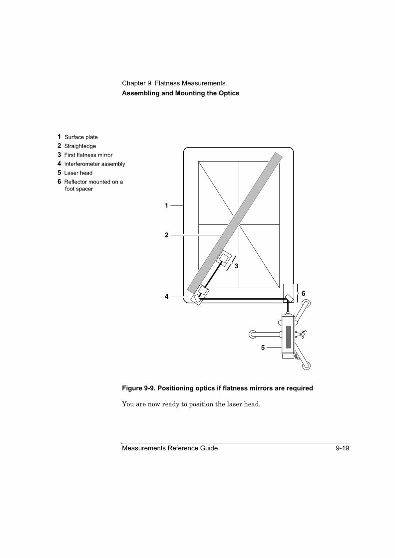
Chapter 9 Flatness MeasurementsAssembling and Mounting the Optics
Measurements Reference Guide 9-19
Figure 9-9. Positioning optics if flatness mirrors are required
You are now ready to position the laser head.
1 Surface plate2 Straightedge3 First flatness mirror 4 Interferometer assembly5 Laser head6 Reflector mounted on a
foot spacer
1
2
5
4 6
3
Chapter 9 Flatness MeasurementsPositioning the Laser Head
9-20 Measurements Reference Guide
Positioning the Laser HeadAfter you assemble and mount the optics, you must position the laser head and place the straightedge along the first measurement line.
NOTE To ensure that you can properly set up the optics, the straightedge you use must be long enough to extend past the ends of the diagonals, or you may need more than one straightedge. This allows you to position the interferometer outside of the measurement grid.
Follow these steps:
1 Position the laser head along your first measurement line.
When positioning the laser head, follow these guidelines:
• If you can align the laser head with a measurement line, choose a line and position the laser head so it points along the line (Figure 9-10). Although Figure 9-10 uses the center line as an example, you can choose any line.
• If you cannot align the laser head with a measurement line, choose an edge and position the laser along it (Figure 9-11). Visually align the laser head so the laser beam is approximately 25 mm (1 inch) above the edge of the surface plate. The 25 mm (1 inch) gap leaves room to properly position a flatness mirror. After you have assembled and mounted the optics, you will adjust the laser head more precisely.

Chapter 9 Flatness MeasurementsPositioning the Laser Head
Measurements Reference Guide 9-21
Figure 9-10. Initially positioning the laser head and straightedge if flatness mirrors are not required
1 Laser head2 Surface plate3 Straightedge positioned
along the first measurement line
4 Nameplate
1 2 3 4
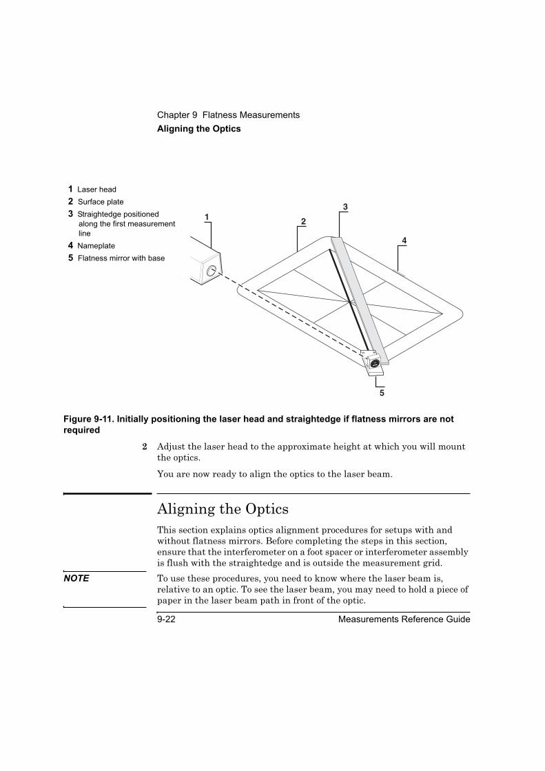
Chapter 9 Flatness MeasurementsAligning the Optics
9-22 Measurements Reference Guide
Figure 9-11. Initially positioning the laser head and straightedge if flatness mirrors are not required
2 Adjust the laser head to the approximate height at which you will mount the optics.
You are now ready to align the optics to the laser beam.
Aligning the OpticsThis section explains optics alignment procedures for setups with and without flatness mirrors. Before completing the steps in this section, ensure that the interferometer on a foot spacer or interferometer assembly is flush with the straightedge and is outside the measurement grid.
NOTE To use these procedures, you need to know where the laser beam is, relative to an optic. To see the laser beam, you may need to hold a piece of paper in the laser beam path in front of the optic.
1 Laser head2 Surface plate3 Straightedge positioned
along the first measurement line
4 Nameplate5 Flatness mirror with base
31 2
1077
0AANG
ULA
R INTERFEROMETER
HEWLETT-PACKARD1 A 0 1 0 1
5
4

Chapter 9 Flatness MeasurementsAligning the Optics
Measurements Reference Guide 9-23
WARNING DO NOT STARE DIRECTLY AT THE LASER LIGHT BEAM OR THE BEAM REFLECTED FROM A POLISHED SURFACE. (IT IS SAFE TO LOOK AT THE DOTS OF LIGHT REFLECTED ON AN UNPOLISHED SURFACE.)
To align the optics, begin by following these steps:
1 Set the laser head’s upper port to the small aperture by turning the upper aperture control (Figure 2-13).
2 Rotate the target into position on the laser head’s lower port by turning the lower aperture control (Figure 2-13).
3 Set the laser head’s turret ring to OTHER (Figure 2-13).
4 Attach a target to the interferometer on the side facing the laser beam coming from the laser head so the target’s cross hairs are below the target’s opening and the edges of the target line up as evenly as possible with the edge of the interferometer.
If you are not using flatness mirrors, continue with the next section, “Aligning the optics if you are not using flatness mirrors.”
If you are using flatness mirrors, go directly to “Aligning the optics if you are using flatness mirrors.”
Aligning the optics if you are not using flatness mirrorsTo align the optics if you are not using flatness mirrors, follow these steps:
1 Adjust the laser head so the laser beam enters the hole of the target mounted on the interferometer.
You can adjust the laser head by pitching, yawing, or translating it, or all three.
2 Move the reflector so its foot spacer touches the interferometer assembly’s base.
Chapter 9 Flatness MeasurementsAligning the Optics
9-24 Measurements Reference Guide
3 Adjust the laser head so:
• the return beam is centered on the target covering the laser head’s return port (you can temporarily remove the target to see the return beam), and
• the laser beam maintains its position in the center of the interferometer’s target.
You can adjust the laser head by tilting, turning, or translating it, or all three.
You are now ready to align the laser beam to the optics’ travel path. Go directly to “Aligning the Laser Beam to the Optics’ Travel Path.”
Aligning the optics if you are using flatness mirrors This section explains how to align the optics using either one or two flatness mirrors.
1 Align the laser head so the beam strikes the first flatness mirror.
If you are using just one flatness mirror, align the laser head so the beam strikes the center of that flatness mirror.
2 Move the reflector so its foot spacer touches the interferometer assembly’s base.
3 Position the flatness mirror.
• If you are using two flatness mirrors, turn the first flatness mirror so the laser beam is vertically in line with the flatness mirror on the interferometer assembly. Continue with step 4.
• If you are using just one flatness mirror, turn it so the beam is vertically in line with the hole in the interferometer’s target. Then, skip to step 6.
4 Tilt the laser head so the beam enters the flatness mirror on the interferometer assembly.
Chapter 9 Flatness MeasurementsAligning the Laser Beam to the Optics’ Travel Path
Measurements Reference Guide 9-25
If the beam moves out of the first flatness mirror, translate the laser head vertically until the beam enters the first flatness mirror again.
5 Turn the flatness mirror on the interferometer assembly so that the beam is vertically in line with the hole in the interferometer’s target.
6 Translate the laser head vertically so the beam enters the hole in the interferometer’s target.
7 Remove the target from the interferometer.
8 Turn the flatness mirror on the interferometer assembly so that the return beam is vertically in line with the target covering the laser head’s return port.
Temporarily re-install the target and verify that the beam is still in the hole on the target. If not, rotate the flatness mirror(s) so the beam maintains its position in the target’s hole.
9 Tilt the laser head up or down until the return beam centers on the target covering the laser head’s return port.
Be sure the beam maintains its position in the center of the flatness mirror and the target’s hole.
10 Secure the first flatness mirror and the interferometer assembly to the surface plate, maintaining the return beam’s position in the center of the laser head’s target.
You are now ready to align the laser beam to the optics’ travel path.
Aligning the Laser Beam to the Optics’ Travel PathFollow the instructions in “Aligning the Laser Beam to the Machine’s Travel Path for Long-Range Measurements” in Chapter 2. However, note these exceptions:
Chapter 9 Flatness MeasurementsCompleting the Set Up Flatness Screen
9-26 Measurements Reference Guide
• Use the procedures in Chapter 2 regardless of the length of your measurement line.
• Instead of moving the machine’s moveable part, move the reflector.
You are now ready to complete the Set Up FLATNESS screen.
Completing the Set Up Flatness ScreenBefore checking the alignment for beam strength, you must complete the Set Up FLATNESS screen. This screen allows you to supply the software with general measurement setup information, such as the foot spacer length. To complete this screen, follow these steps:
1 On the Other Measurements screen, select Flatness.
The Set Up FLATNESS screen is displayed (Figure 9-12).
2 In the Measurement Units box, select either English or Metric.
Your selection indicates the units for angles and for foot spacer and line lengths. It also determines the display units for the diagonal length on the Set Up FLATNESS screen and the Laser Error and Target position units on the Collect Data: FLATNESS screen.

Chapter 9 Flatness MeasurementsCompleting the Set Up Flatness Screen
Measurements Reference Guide 9-27
Figure 9-12. Set Up FLATNESS screen
3 In the Axis Lengths box, enter the lengths of perimeter lines 3 and 6 (see Figure 9-3 or 9-4).
You can enter data into either field first. Whenever you enter data in either box, the diagonal field goes blank. The diagonal data re-displays when you press Enter or tab out of this field.
After you complete both fields, the software calculates the length of the diagonal and displays it below the AG field.

Chapter 9 Flatness MeasurementsCompleting the Set Up Flatness Screen
9-28 Measurements Reference Guide
4 In the Optics box, do the following:
a. In the Foot Spacing field, enter the size of the foot spacer you chose.
b. If your interferometer has a calibration factor stamped on it, enter the factor here. Otherwise, leave this field at 1.
Your optics will only have a calibration factor if you have had them calibrated. This calibration provides accuracy within 0.2% of your reading.
5 Select the line you plan to measure by clicking the corresponding numbered button on the diagram.
Be sure that the number of stations in the Line Setup box (labeled Line #) equals the number of stations for that line on your measurement grid. If it does not, recheck your foot spacer and line lengths.
NOTE If you have already measured one or more lines, these lines are grayed out. If you want, you can select one of these lines to measure again, for example, to average the measurement data with the existing data.
After you select a line, the number of stations on the line is displayed in the Line Setup box. If you selected a line that you have already measured, an option box is displayed in the Line Setup box.
6 In the Line Setup box, do the following:
a. Indicate the optic’s direction of travel for this measurement by selecting the appropriate button on the left side of the Line Setup box.
b. If you selected a line that you have already measured, indicate how you want the software to process the measurement data you are about to collect:
• To overwrite the existing data with the data you are about to collect, select Overwrite Existing Data.
• To average the data you are about to collect with the existing data, select Average with Existing Data.
You are now ready to check the alignment for beam strength.

Chapter 9 Flatness MeasurementsCompleting the Set Up Flatness Screen
Measurements Reference Guide 9-29
Checking the alignment for beam strengthBefore completing the steps in this section, ensure that the reflector is at its initial position.
1 Set the laser head’s upper port to the large aperture.
2 Move the reflector along the travel path and check the Beam Strength indicator on the Set Up FLATNESS screen.
• If the beam strength is greater than 60 percent (and the indicator area is green if you have a color monitor), go directly to “Making the measurement.”
• If the beam strength is 20 to 60 percent (and the indicator area is yellow if you have a color monitor), you can make the measurement, but you risk losing the laser beam return signal during a measurement. If you lose the signal during a measurement, you will have to improve the laser beam alignment and take data starting at the last valid point. You may want to follow the steps in “Improving beam strength.” Otherwise, go directly to “Making the measurement.”
• If the beam strength is less than 20 percent (and the indicator area is red if you have a color monitor), follow the steps in “Improving beam strength.”
When you have completed the Set Up FLATNESS screen, choose Collect Data.
The Collect Data: FLATNESS screen is displayed (Figure 9-13).

Chapter 9 Flatness MeasurementsCompleting the Set Up Flatness Screen
9-30 Measurements Reference Guide
Figure 9-13. Collect Data: FLATNESS screen
Improving beam strengthTo improve beam strength, do the following:
• The optics are positioned so that the laser beam passes cleanly through the optics (Figures 9-8 and 9-9, or 9-16 through 9-18). If they are not, repeat the steps in “Mounting the optics.”
• The optics are securely assembled and mounted. If they are not, remount the optics, tighten the attachment screws, and repeat the steps in “Aligning the optics if you are not using flatness mirrors” or Aligning the optics if you are using flatness mirrors.
• The optics are clean. To clean the optics, follow the directions in the Agilent 5530 Getting Started Guide.
Chapter 9 Flatness MeasurementsCompleting the Set Up Flatness Screen
Measurements Reference Guide 9-31
If you cannot obtain 60 percent beam strength, call your local support person or Agilent Technologies customer support. Refer to back of this guide for a list of Agilent Technologies service and support centers.
Making the measurementIn this procedure, you make manual measurements as you move the reflector. This section explains how to make measurements using the Record button in the software and on the optional remote control unit.
Before making your measurement, check two things:
1. The repeatability of the optics at rest — Be sure that the reading displayed does not change when the optics are still. If the display does change, do the following:
• Ensure that the foot spacer is sitting flat on the surface plate.
• The optic is securely fastened to the foot spacer.
• The surface plate is clean.
• The optics are thermally stable — 15 ° to 25 °C (59 ° to 77 °F)
2. The optics coming to rest at a station — Check your measurement’s repeatability by stopping at each station along the travel path and looping back to the previous station to ensure that the readings are the same. There will be some variation since you are manually moving the optics, but try to place the optics in the same spot each time.
Non-repeatable readings can also be caused by dirt, dust, granite flakes under the feet, or temperature variations in the optics. Minimize finger contact with the optics.

Chapter 9 Flatness MeasurementsCompleting the Set Up Flatness Screen
9-32 Measurements Reference Guide
Measuring the first line on the gridTo make the measurement, follow these steps:
1 Move the reflector to the first station.
2 On the Collect Data: FLATNESS screen, select Reset Position.
This tells the system that the current position of the reflector is the “zero” point from which the surface plate flatness will be measured (that is, the first data point for this line).
If necessary, use the online help to complete the rest of the fields on this screen.
3 Select Record.
If you are using the optional remote control unit, press the Record button.
4 Move the reflector to the second data point on the line to be measured.
5 Select Record.
6 Continue, moving the reflector to each station along the line and recording measurements until you have recorded data at the last station on the line.
After the last measurement on each line is recorded, the Analyze Data: FLATNESS screen is displayed (Figure 9-14).
NOTE If at any point the Reset Laser message flashes, the laser beam path has been broken. Move the reflector back to the first point measured, then select Reset Position to reset the system. Now you can return to the last station you measured (check your repeatability) and continue taking measurements.
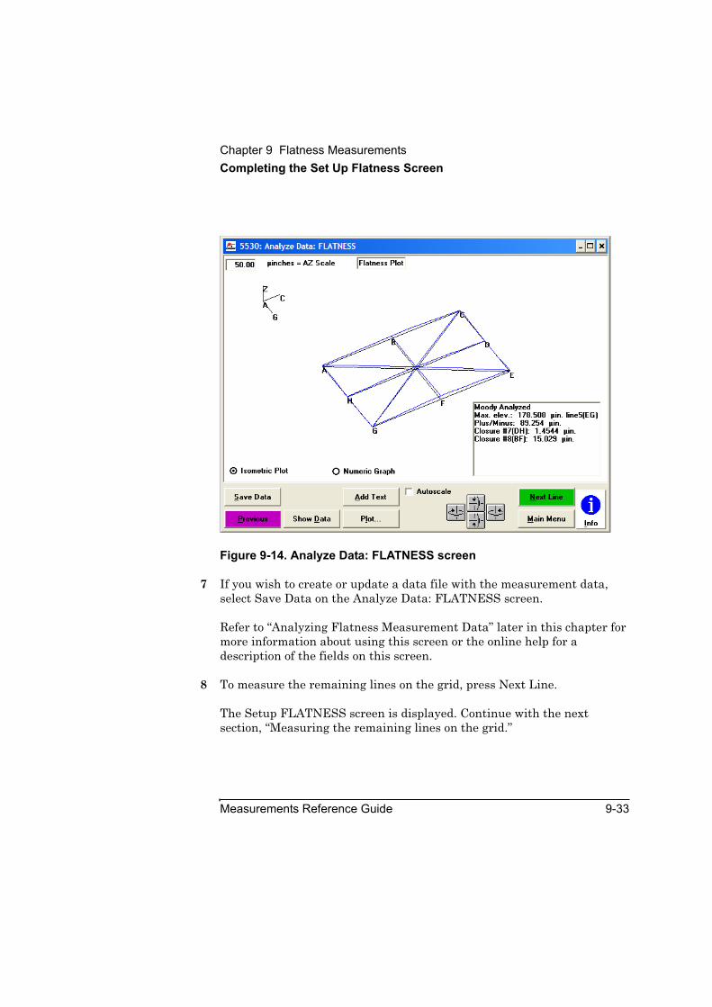
Chapter 9 Flatness MeasurementsCompleting the Set Up Flatness Screen
Measurements Reference Guide 9-33
Figure 9-14. Analyze Data: FLATNESS screen
7 If you wish to create or update a data file with the measurement data, select Save Data on the Analyze Data: FLATNESS screen.
Refer to “Analyzing Flatness Measurement Data” later in this chapter for more information about using this screen or the online help for a description of the fields on this screen.
8 To measure the remaining lines on the grid, press Next Line.
The Setup FLATNESS screen is displayed. Continue with the next section, “Measuring the remaining lines on the grid.”
Chapter 9 Flatness MeasurementsCompleting the Set Up Flatness Screen
9-34 Measurements Reference Guide
Measuring the remaining lines on the gridTo measure the remaining lines on the grid, follow these steps:
1 If you have not already done so, select Next Line on the Analyze Data: FLATNESS screen.
The Set Up FLATNESS screen (Figure 9-12) is displayed.
You can change the measurement units and optics’ direction of travel on the Set Up FLATNESS screen using the instructions in “Completing the Set Up Flatness Screen,” earlier in this chapter.
2 If you are not using flatness mirrors, move the laser head so it points along the next measurement line.
If you are using flatness mirrors, continue with step 3.
3 Set up the optics for the measurement.
If you are not using flatness mirrors, set up the optics using the appropriate instructions in “Mounting the optics,” and “Aligning the optics if you are not using flatness mirrors” or” “Aligning the optics if you are using flatness mirrors” earlier in this chapter.
If you are using flatness mirrors, set up the optics using one of the setups shown in Figures 9-15 through 9-17.
4 Align the optics using the instructions in “Aligning the Optics,” earlier in this chapter.
5 Align the laser beam to the optics’ travel path using the instructions in “Aligning the Laser Beam to the Optics’ Travel Path,” earlier in this chapter.
6 Check the alignment for beam strength using the instructions in “Checking the alignment for beam strength,” earlier in this chapter.
7 Repeat the steps in “Measuring the first line on the grid.”

Chapter 9 Flatness MeasurementsCompleting the Set Up Flatness Screen
Measurements Reference Guide 9-35
8 Repeat steps 1 through 8 in this section until you have measured all of the measurement lines.
When the Analyze Data: Flatness window displays after you measure the last line, continue with the steps in “Analyzing Flatness Measurement Data.”
Figure 9-15. Positioning optics for measuring diagonal lines (lines 1 and 2) when using flatness mirrors
1 Laser head2 Straightedge3 Interferometer assembly4 First flatness mirror5 Reflector mounted on a
foot spacer
2
1
5
4
3

Chapter 9 Flatness MeasurementsCompleting the Set Up Flatness Screen
9-36 Measurements Reference Guide
Figure 9-16. Positioning optics for measuring lines parallel to the laser head (lines 3, 5, and 7) when using flatness mirrors
1 Laser head2 Interferometer assembly3 Reflector mounted on a
foot spacer4 Straightedge5 First flatness mirror
4
1
5
2
3
10770AAN
GULAR
INTERFEROMETER
HEWLETT-PACKARD
1 A 0 1 0 1
1077
0AAN
GULAR INTERFEROMETER
HEWLETT-PACKARD
1 A 0 1 0 1
10770AAN
GULAR
INTERFEROMETER
HEWLETT-PACKARD
1 A 0 1 0 1
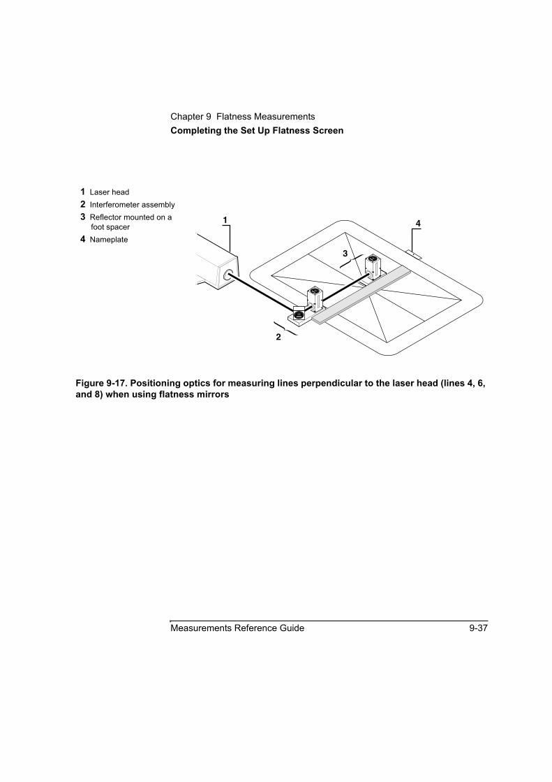
Chapter 9 Flatness MeasurementsCompleting the Set Up Flatness Screen
Measurements Reference Guide 9-37
Figure 9-17. Positioning optics for measuring lines perpendicular to the laser head (lines 4, 6, and 8) when using flatness mirrors
1 Laser head2 Interferometer assembly3 Reflector mounted on a
foot spacer4 Nameplate
41
2
310770A
ANGULAR
INTERFEROMETER
HEWLETT-PACKARD
1A0101
10770AANGU
LARINTERFEROMETER
HEWLETT-PACKARD
1A0101
1077
0AAN
GULAR INTERFEROMETER
HEWLETT-PACKARD
1 A 0 1 0 1

Chapter 9 Flatness MeasurementsAnalyzing Flatness Measurement Data
9-38 Measurements Reference Guide
Analyzing Flatness Measurement DataThe Analyze Data: FLATNESS screen presents a graphical data display and a numerical analysis of the measurement data set. You can display data in two formats: isometric and numeric.
• To view data in the graphic format, select Isometric Plot from the option box above the Save Data button in the lower left corner of the screen.
• To view data in the numeric format, select Numeric Graph from the option box above the Add Text button in the lower left corner of the screen.
As with Analyze Data screens for all other measurements, you can use this screen to display the measurement dataset. To do this, select Show Data (or press Alt D).
Understanding the isometric formatThe isometric format shows the measurement grid with an isometric plot of the measurement data as shown in Figure 9-14. The functions available with this format are explained below.
Rotating the grid and plotAt the bottom of the screen, below the Autoscale checkbox, are four rotation buttons. Use these to rotate the grid and plot vertically and horizontally to show different views of the display.
Because rotating the grid and plot can hide line identification letters and make it difficult to know how the grid and plot are oriented, the three axes below the AZ Scale box show the current orientation of the grid and plot. As you rotate the grid and plot, the three axes rotate.
Chapter 9 Flatness MeasurementsAnalyzing Flatness Measurement Data
Measurements Reference Guide 9-39
Changing the AZ axis scaleTo better view the plot of the measurement data, you can change the AZ axis scale. The distance in the AZ scale box is equivalent to the length of the AZ segment immediately below it. The isometric graph is plotted using the same AZ scale.
This exaggerates the distance of the plot from the grid, making it easier to see how the measurement data deviates from the zero point.
Use the AZ Scale box to change the AZ axis scale. To change the AZ axis scale, do the following:
1 Place the cursor in the AZ Scale box.
2 Enter a number from .001 to 1000, then press Enter.
Alternatively, you can let the software automatically change the AZ axis scaling to an optimal value. To do so, select the Autoscale checkbox. This checkbox is at the bottom of the screen to the right of the Add Text button.
Typing measurement commentsIn the upper right corner of the screen is a box in which you can type comments or other information pertinent to the measurement. To enter information in this box, select the Add Text button (or press Alt A).
If necessary, you can move the box. To do so, place the cursor in the box, press the mouse button, drag the box to where you want to move it, then release the mouse button.
Viewing data analysis resultsBelow the grid is a box that gives the following measurement analysis information (the box can be moved to a convenient location by using the mouse to click and drag it):
• the greatest vertical deviation from the zero point and the line that contains this deviation, and
• the closure error for Lines 7 and 8
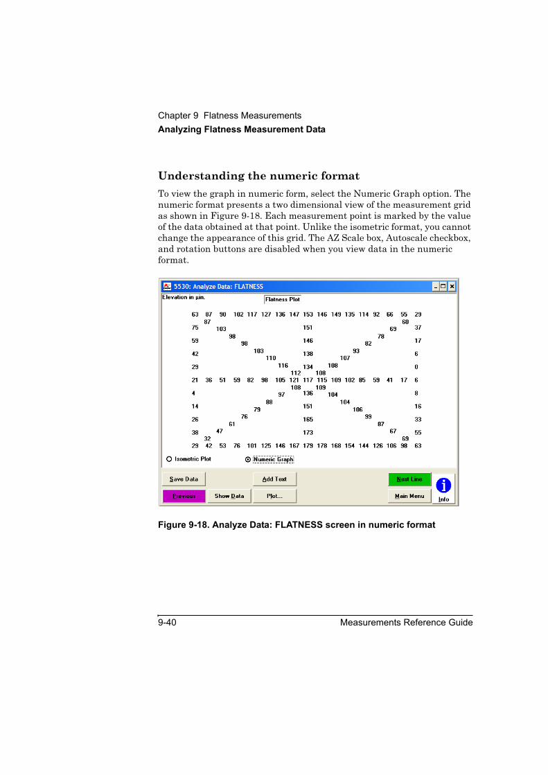
Chapter 9 Flatness MeasurementsAnalyzing Flatness Measurement Data
9-40 Measurements Reference Guide
Understanding the numeric formatTo view the graph in numeric form, select the Numeric Graph option. The numeric format presents a two dimensional view of the measurement grid as shown in Figure 9-18. Each measurement point is marked by the value of the data obtained at that point. Unlike the isometric format, you cannot change the appearance of this grid. The AZ Scale box, Autoscale checkbox, and rotation buttons are disabled when you view data in the numeric format.
Figure 9-18. Analyze Data: FLATNESS screen in numeric format

10
Way Straightness Measurements

Chapter 10 Way Straightness Measurements
10-2 Measurements Reference Guide
IntroductionThis chapter explains how to make way straightness measurements at multiple points along a machine part such as a milling machine way. Since most of the procedures for way straightness measurements are similar to those for flatness measurements, you are referred to Chapter 9 for certain instructions.
Before performing the procedures described in this chapter, you must fully understand and know how to perform the procedures presented in the Agilent 5530 Getting Started Guide.
For measurement operating specifications, see the way straightness measurement specifications in Appendix A. Since you use the angular interferometer and reflector to make way straightness measurements, see the angular measurement specifications in Appendix A for optics specifications.
Figure 9-1 shows the required optics and mounting hardware for way straightness measurements.

Chapter 10 Way Straightness MeasurementsSetting Up for the Measurement
Measurements Reference Guide 10-3
Setting Up for the MeasurementTo set up for the measurement, follow these steps:
1 Follow steps 1 through 5 in “Setting Up for the Measurement” in Chapter 9.
2 Select Way Strat from the Other Measurements screen.
The Set Up WAY STRAIGHTNESS screen is displayed (Figure 10-1).
Figure 10-1. Set Up WAY STRAIGHTNESS screen
Marking foot spacer intervalsTo make measurements along the machine way, you must mark measurement points, called “stations” on the way. First, choose a foot spacer for the interferometer. The foot spacer kit includes three
Chapter 10 Way Straightness MeasurementsAssembling, Mounting, and Aligning the Optics on the Target Machine
10-4 Measurements Reference Guide
foot spacers: 50 mm (2 inch), 102 mm (4 inch), and 152 mm (6 inch). These sizes are actually the distances between the leading and trailing feet of the foot spacers rather than the overall length of the foot spacers.
When choosing a foot spacer, remember that the smaller the foot spacer, the longer it will take you to perform the entire measurement process, but the better your measurement resolution will be.
After you choose a foot spacer, mark the stations on the machine way. Make sure that the interval between the marks on the way is the same as the distance between the leading and trailing feet on the chosen foot spacer.
After you have marked the stations, calculate the combined length of the stations in millimeters or inches. Write down this length; you will need to enter it on the Set Up WAY STRAIGHTNESS screen.
NOTE The figures in this chapter use a milling machine way as an example. Although the equipment or machinery you are checking for way straightness may be different, the procedures described here still apply.
Assembling, Mounting, and Aligning the Optics on the Target MachineTo assemble, mount, and align the optics on the target machine, follow these steps:
1 To assemble the optics, attach the interferometer and reflector to foot spacers (Figure 9-7).
2 Mount the optics on the machine way (Figure 10-2).
You may need to make a special holder, similar to a way bearing, that follows the way and carries the reflector during the measurement. This also allows you to measure side to side flatness.
3 To align the optics, follow the instructions in “Aligning the Optics” then “Aligning the optics if you are not using flatness mirrors” in Chapter 9.

Chapter 10 Way Straightness MeasurementsPositioning the Laser Head
Measurements Reference Guide 10-5
Positioning the Laser HeadPosition the laser head at one end of the way you plan to measure (Figure 10-2).
Figure 10-2. Positioning optics for a way straightness measurement
1 Straightedge2 Angular reflector mounted on
a foot spacer3 Angular interferometer 4 Laser head5 Machine way
5
3
2
4
10770AAN
GULA
R INTERFEROMETER
1 A 0 1 0 1
10770AAN
GULA
R INTERFEROMETER
1 A 0 1 0 1
1
Chapter 10 Way Straightness MeasurementsAligning the Laser Beam to the Optics’ Travel Path
10-6 Measurements Reference Guide
Aligning the Laser Beam to the Optics’ Travel PathFollow the instructions in “Aligning the Laser Beam to the Machine’s Travel Path for Long-Range Measurements” in Chapter 2. However, note these exceptions:
• Use the procedures in Chapter 2 regardless of the length of your measurement line.
• Instead of moving the machine’s moveable part, move the reflector.
You are now ready to complete the Set Up WAY STRAIGHTNESS screen.
Completing the Set Up Way Straightness screenThis screen allows you to supply the software with general measurement setup information, such as the foot spacer length. To complete this screen, follow these steps:
1 On the Other Measurements screen, select Way Strat.
The Set Up WAY STRAIGHTNESS screen is displayed (Figure 10-3).

Chapter 10 Way Straightness MeasurementsCompleting the Set Up Way Straightness screen
Measurements Reference Guide 10-7
Figure 10-3. Set Up WAY STRAIGHTNESS screen
2 Complete the fields on this screen using the applicable instructions in “Completing the Set Up Flatness Screen,” in Chapter 9. However, in the Way Length field, type the combined length of the stations you marked on the way.
You are now ready to check the alignment for beam strength.
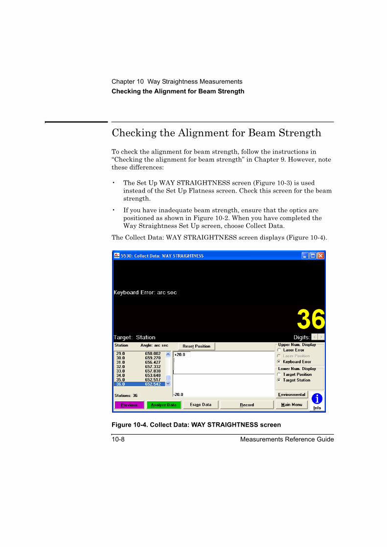
Chapter 10 Way Straightness MeasurementsChecking the Alignment for Beam Strength
10-8 Measurements Reference Guide
Checking the Alignment for Beam StrengthTo check the alignment for beam strength, follow the instructions in “Checking the alignment for beam strength” in Chapter 9. However, note these differences:
• The Set Up WAY STRAIGHTNESS screen (Figure 10-3) is used instead of the Set Up Flatness screen. Check this screen for the beam strength.
• If you have inadequate beam strength, ensure that the optics are positioned as shown in Figure 10-2. When you have completed the Way Straightness Set Up screen, choose Collect Data.
The Collect Data: WAY STRAIGHTNESS screen displays (Figure 10-4).
Figure 10-4. Collect Data: WAY STRAIGHTNESS screen

Chapter 10 Way Straightness MeasurementsMaking the Measurement
Measurements Reference Guide 10-9
Making the MeasurementTo make the measurement, follow the instructions in “Making the measurement” in Chapter 9. However, note these differences:
• Use the Reset Position and the Record buttons on the Collect Data: WAY STRAIGHTNESS screen (Figure 10-4) instead of on the Collect Data: Flatness screen.
• After you record the last measurement, the Analyze Data: WAY STRAIGHTNESS screen (Figure 10-5) is displayed. To create a data file with the measurement data or to update an existing data file, select Save Data on this screen. Refer to the Agilent 5530 Getting Started Guide and online help for more information about using this screen.
Ignore the instructions in “Measuring the remaining lines on the grid” in Chapter 9.
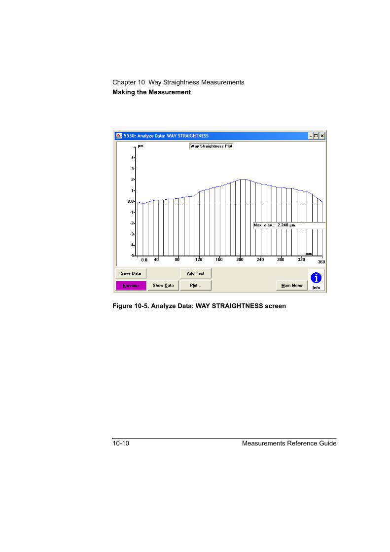
Chapter 10 Way Straightness MeasurementsMaking the Measurement
10-10 Measurements Reference Guide
Figure 10-5. Analyze Data: WAY STRAIGHTNESS screen

11
Diagonal Measurements
Chapter 11 Diagonal MeasurementsIntroduction
11-2 Measurements Reference Guide
IntroductionThis chapter explains how to make diagonal measurements, used for volumetric analysis, as described in ANSI standard B5.54. It also describes how to set up the measurement optics to make measurements on a slant-bed lathe.
Before performing the procedures described in this chapter, you must fully understand and know how to perform the procedures presented in the Agilent 5530 Getting Started Guide.
The Diagonal Measurement procedure differs from other Agilent 5530 calibrator measurement procedures in that it does not proceed along a single path from Set-Up Laser to Analyze Data. The data required for a diagonal measurement consists of the data from four linear measurements, each made along a body diagonal of the workspace you want to evaluate. If you already have existing data you want to analyze, you can simply recall it, using the Recall Data button on the Main Menu. If you need to acquire data for analysis, the preferred path is to start with the diagonal measurement’s Set Up Laser menu and then proceed along the Set Up Measurement-Collect Data-Analyze Data path; note that this process must be performed for each diagonal axis whose data you need.
To help visualize the major steps in making a diagonal measurement, refer to the flowchart in Figure 11-1.
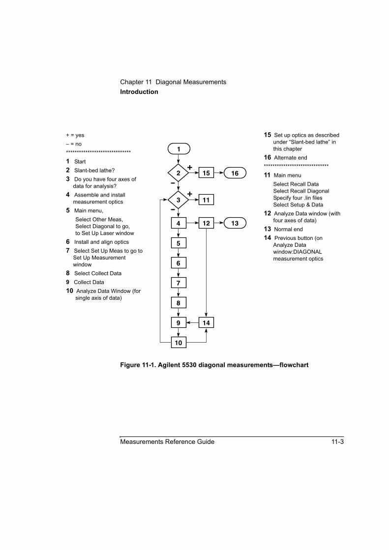
Chapter 11 Diagonal MeasurementsIntroduction
Measurements Reference Guide 11-3
Figure 11-1. Agilent 5530 diagonal measurements—flowchart
+ = yes– = no******************************1 Start2 Slant-bed lathe?3 Do you have four axes of
data for analysis?4 Assemble and install
measurement optics5 Main menu,
Select Other Meas,Select Diagonal to go,to Set Up Laser window
6 Install and align optics7 Select Set Up Meas to go to
Set Up Measurement window
8 Select Collect Data9 Collect Data10 Analyze Data Window (for
single axis of data)
15 Set up optics as described under “Slant-bed lathe” in this chapter
16 Alternate end******************************11 Main menu
Select Recall DataSelect Recall DiagonalSpecify four .lin filesSelect Setup & Data
12 Analyze Data window (with four axes of data)
13 Normal end14 Previous button (on
Analyze Data window:DIAGONAL measurement optics
13
1
2 15 16
3
5
6
7
8
9
11
12
14
10
4
+
--+
--

Chapter 11 Diagonal MeasurementsBackground — Why Diagonal Measurements?
11-4 Measurements Reference Guide
Background — Why Diagonal Measurements?The goal in calibrating a machine tool or coordinate measuring machine (CMM) is to determine its volumetric accuracy — that is, its ability to position accurately anywhere in the work zone. This cannot be done directly, but can be inferred by measuring the six degrees of freedom for each axis and the squareness of X, Y, and Z to each other. This can be a time-consuming process, and in many cases the time spent is not justified.
Thus, there is a need for a quick assessment of volumetric performance.
Measurement of work zone diagonals provides just such an assessment. As the spindle is traversed along a body diagonal of the work zone, all axes must move in concert in order to position accurately along the line. Diagonal measurements are useful in machine tool acceptance testing or in a periodic maintenance program to quickly assess the condition of a machine.
Agilent 10768A Diagonal Measurement KitThe Agilent 10768A Diagonal Measurement Kit, shown in Figure 11-2A/B, is an optical accessory to the Agilent 5530 Dynamic Calibrator. It enables precise alignment of the laser beam to the body diagonals of the work zone of a milling machine or CMM. It also simplifies calibration of slant-bed lathes. The optics can be repeatedly aligned to the same machine diagonals at future calibrations. The Agilent 10768A enables implementation of ANSI/ASME standards B89 and B.5 for CMMs and machine tools, respectively.
The Agilent 10768A Diagonal Measurement Kit provides hardware that allows you to use Agilent Technologies linear measurement optics (see Figure 11-3) in an Agilent 5530 Dynamic Calibrator to make distance measurements along any linear machine travel path.

Chapter 11 Diagonal MeasurementsAgilent 10768A Diagonal Measurement Kit
Measurements Reference Guide 11-5
A diagonal measurement is a linear displacement measurement along a line that is not necessarily parallel to nor perpendicular to one or more of the orthogonal major axes (X, Y, and Z) of the machine being calibrated. A typical diagonal measurement path is the body diagonal of a work zone (see Figure 11-4). A typical use for a diagonal measurement is to assess the volumetric performance of a machine tool or coordinate measuring machine. See ANSI/ASME Standard B5.54 for additional information about assessing volumetric performance using diagonal measurements.
The Agilent 10768A kit can also be used to simplify the calibration of a slant-bed lathe, as described in “Agilent 10769A Beam Steering Mirror.”
Much of the basic information you should know in order to perform a diagonal measurement is contained in Chapter 2, “Linear Measurements,” of this guide.

Chapter 11 Diagonal MeasurementsAgilent 10768A Diagonal Measurement Kit
11-6 Measurements Reference Guide
Figure 11-2A. Agilent 10768A Diagonal Measurement Kit (Part 1 of 2)
5
8
6
7
11
12
10
4
9
1
2
3
13

Chapter 11 Diagonal MeasurementsAgilent 10768A Diagonal Measurement Kit
Measurements Reference Guide 11-7
Figure 11-2B. Agilent 10768A Diagonal Measurement Kit (Part 2 of 2)
ReferenceNumber
Description Agilent Part Number
Quantity in 10768A
Quantity in 10769A
Quantity in 10744A
1 post-medium 10776-20008 2 0 2
2 post-long 10785-20005 1 1 5 (Option 005 adds 5)
3 post-stub 10768-20213 1 0 2
4 hex key 5 mm 8710-2040 1 1 1
5 hex key 4 mm 8710-2041 1 1 1
6 hex key 2.5 mm 8710-1181 1 1 1
7 right-angle clamp 10768-20207 2 0 3
8 beam-steering assembly 10768-60201 1 1 0
9 adapter plate 10768-20215 2 0 1
10 base-large 10768-20214 1 1 1
11 flexible ball-joint assembly 10768-60203 1 0 1
12 alignment target 10767-67001 1 1 0
13 gusset 10744-00001 0 0 3
not shown lens tissue 9281-0363 1 pkg 1 pkg 1 pkg
not shown adjustable triangle 9300-1730 1 0 0
not shown setscrew–brass tip, M10× 1.5 0515-2336 1 1 0
not shown setscrew–brass tip, M5× 0.8 0515-2358 1 1 0
not shown cap screw-socket-head-M3× 25 long
0515-2359 4 4 4
not shown setscrew M10× 20 0515-2362 1 0 3
not shown flathead screw-M3× 0.5× 16long
0515-0078 4 0 2
Chapter 11 Diagonal MeasurementsAgilent 10769A Beam Steering Mirror
11-8 Measurements Reference Guide
Agilent 10769A Beam Steering MirrorThe Agilent 10769A Beam Steering Mirror provides the beam-steering hardware from the Agilent 10768A kit, along with some mounting hardware. This combination of parts allows you to deflect a laser beam at any angle, in either the vertical or the horizontal polarization plane of the beam. One use of this hardware is for laser measurements and calibration of slant-bed lathes. In this case, the beam steering mirror is used to deflect the beam from the laser head upward, through the interferometer, along the lathe’s cross slide; the other measurement optics and hardware can be the same as for standard measurements.
You can use one or more Agilent 10769A mirrors to create a path from the laser head to an interferometer in an otherwise inaccessible position. A typical use is with the Agilent 10768A Diagonal Measurement Kit on a milling machine in which the table moves in only one axis.
Agilent 10767B Lightweight RetroreflectorThe Agilent 10767B Lightweight Retroreflector is intended for use as the measurement retroreflector in situations where the weight of the Agilent 10767A retroreflector might distort the machine — for instance, a small robot or a small coordinate measuring machine (CMM). The two retroreflectors use identical optical elements, the only difference is in their housings.
Agilent 10744A Accessory KitThe Agilent 10744A Accessory Kit provides mounting hardware you can use with many Agilent Technologies measurement optics to meet the physical needs of your measurement situation. For instance, with multiple posts and the large base, you can build a tall, rigid tower for mounting measurement optics high in the center of the machine’s work zone.
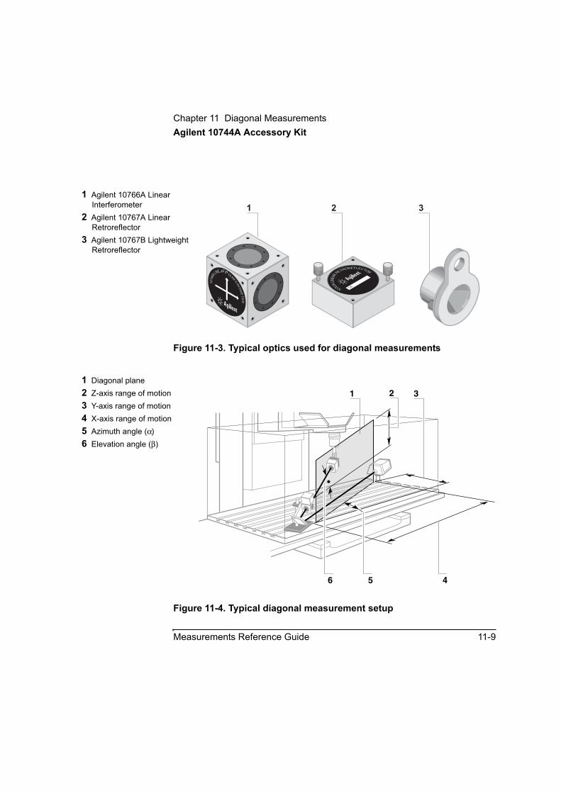
Chapter 11 Diagonal MeasurementsAgilent 10744A Accessory Kit
Measurements Reference Guide 11-9
Figure 11-3. Typical optics used for diagonal measurements
Figure 11-4. Typical diagonal measurement setup
1 Agilent 10766A Linear Interferometer
2 Agilent 10767A Linear Retroreflector
3 Agilent 10767B Lightweight Retroreflector
1076
6ALINEAR INTER
FE
RO
ME
TE
R
10767ALIN
EARRETROREFLECTOR
1A
1 2 3
1 Diagonal plane2 Z-axis range of motion3 Y-axis range of motion4 X-axis range of motion5 Azimuth angle (α)6 Elevation angle (β)
2
456
1 3

Chapter 11 Diagonal MeasurementsSetting Up for the Measurement
11-10 Measurements Reference Guide
Setting Up for the MeasurementGuide: This information relates to flowchart item 4 in Figure 11-1.
Previous experience in setting up and making non-diagonal linear measurements can help you learn to set up and make diagonal measurements.
If you have not already done so, perform the following setup procedures before using the rest of the instructions in this chapter to make a diagonal measurement. Refer to the Agilent 5530 Getting Started Guide for complete instructions when installing and starting the system for the first time.
1 Mount the laser head on the tripod and place the tripod near the target machine.
2 Connect the E1735A USB Axis Module and the E1736A USB Sensor Hub to the USB connectors on your PC. Connect the laser head and remote control unit to the axis module. Connect the sensors to the sensor hub.
3 Plug in and turn on all equipment.
Before you set up for diagonal measurements:
a. Determine:
• the type of machine you are working on, and
• which body diagonals or face diagonals will be measured (Figure 11-4)
Examples of machine types are:
• stacked-stage with vertical spindle—table moves in X and Y
• single-slide table—column moves in Y and Z, table moves in X only
Chapter 11 Diagonal MeasurementsCalculating Angles
Measurements Reference Guide 11-11
b. Use the Agilent 5530 calibrator’s Set Up Laser window to calculate the angles required for setup:
• the azimuth angle (α) of the body diagonal planes on the XY plane (Figure 11-4), and
• the elevation angle (β) of the body diagonals, in the diagonal planes
c. Program the machine to traverse the four body diagonals to be measured.
Calculating AnglesThe Agilent 5530 calibrator’s diagonal measurement software calculates the azimuth and elevation angles for you, as you enter the dimensions of the workspace to be analyzed. See distances 2, 3, and 4 in Figure 11-4.
Placing and Using the SensorsSensor placement for diagonal measurements is the same as that for Agilent 5530 calibrator linear measurements. Refer to Chapter 2, “Linear Measurements,” in this guide for information.
Chapter 11 Diagonal MeasurementsAssembling the Interferometer, Reference Retroreflector and Beam Steering Arm
11-12 Measurements Reference Guide
Assembling the Interferometer, Reference Retroreflector and Beam Steering Arm
1 Determine the setup you want to use for your measurement. Refer to Table 11-1 and Figures 11-5 through 11-7, or to notes about previous setups, to determine the interferometer and reference retroreflector assembly arrangement you want to use. Different combinations provide different angle range capabilities. The measurement shown in Figure 11-4 is “far low to near high,” on a stacked-stage, vertical-spindle machine, with the laser head at the right. (The symbol glossary at the end of this chapter describes the symbols used here and in other places in this chapter to indicate general configurations or interferometer configurations.)
2 Assemble the interferometer and reference retroreflector.
In addition to the figures referenced above, you can refer to Figure 11-21 for help. Be sure the retroreflector is tightly fastened to the interferometer.
3 Attach the interferometer assembly you created in step 2 to the beam steering arm, keeping in mind the configuration you want for your measurement. See Figures 11-5 through 11-7.
4 Set this assembly in a safe place while you assemble other pieces of the diagonal measurement hardware.
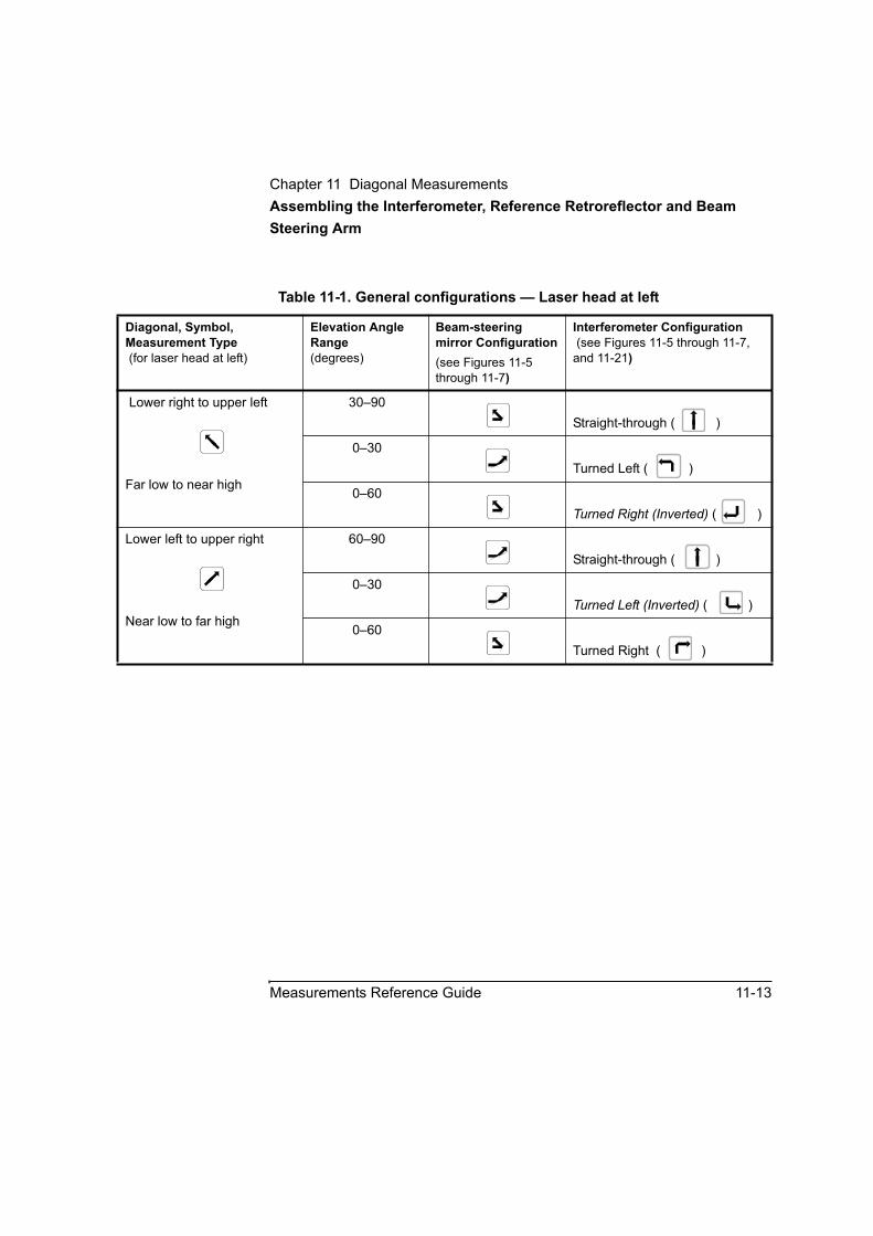
Chapter 11 Diagonal MeasurementsAssembling the Interferometer, Reference Retroreflector and Beam Steering Arm
Measurements Reference Guide 11-13
Table 11-1. General configurations — Laser head at left
Diagonal, Symbol, Measurement Type (for laser head at left)
Elevation Angle Range(degrees)
Beam-steering mirror Configuration(see Figures 11-5 through 11-7)
Interferometer Configuration(see Figures 11-5 through 11-7,
and 11-21)
Lower right to upper left
Far low to near high
30–90Straight-through ( )
0–30Turned Left ( )
0–60Turned Right (Inverted) ( )
Lower left to upper right
Near low to far high
60–90Straight-through ( )
0–30Turned Left (Inverted) ( )
0–60Turned Right ( )
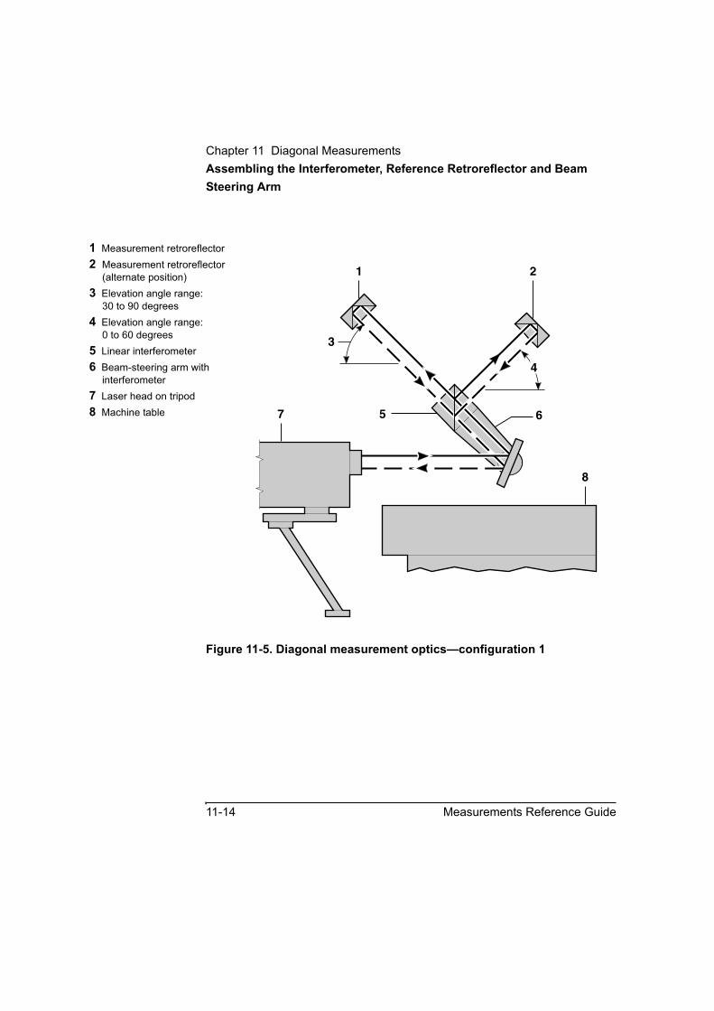
Chapter 11 Diagonal MeasurementsAssembling the Interferometer, Reference Retroreflector and Beam Steering Arm
11-14 Measurements Reference Guide
Figure 11-5. Diagonal measurement optics—configuration 1
1 Measurement retroreflector2 Measurement retroreflector
(alternate position)3 Elevation angle range:
30 to 90 degrees4 Elevation angle range:
0 to 60 degrees5 Linear interferometer6 Beam-steering arm with
interferometer7 Laser head on tripod8 Machine table 6
8
7 5
3
4
1 2

Chapter 11 Diagonal MeasurementsAssembling the Interferometer, Reference Retroreflector and Beam Steering Arm
Measurements Reference Guide 11-15
Figure 11-6. Diagonal measurement optics—configuration 2
1 Measurement retroreflector2 Measurement retroreflector
(alternate position)3 Elevation angle range:
30 to 90 degrees4 Elevation angle range:
0 to 60 degrees5 Linear interferometer6 Beam-steering arm with
interferometer7 Laser head on tripod8 Machine table
1
2
6
8
753
4
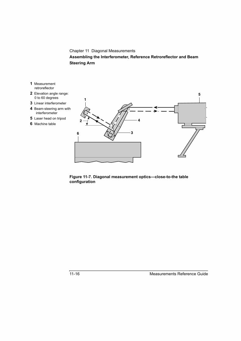
Chapter 11 Diagonal MeasurementsAssembling the Interferometer, Reference Retroreflector and Beam Steering Arm
11-16 Measurements Reference Guide
Figure 11-7. Diagonal measurement optics—close-to-the table configuration
1 Measurement retroreflector
2 Elevation angle range:0 to 60 degrees
3 Linear interferometer4 Beam-steering arm with
interferometer5 Laser head on tripod6 Machine table
6
1
2
5
4
3
Chapter 11 Diagonal MeasurementsAssembling the Interferometer, Post, Base and Clamp
Measurements Reference Guide 11-17
Assembling the Interferometer, Post, Base and ClampIf you are using the right-angle clamp in a post-and-base setup for mounting your interferometer (on the beam steering arm), align the clamp so its long edge is parallel to the edge of the base. This will make alignment of the interferometer to the XY diagonal of the measurement easier. Refer to Figure 11-8.
1 Assemble and tighten the post(s) and base.
2 Slide the right-angle clamp onto the post. Do not tighten the clamp at this time.
3 Tip the assembly on its side on a flat surface so the long edge of the base and the long edge of the clamp are both resting flatly on the surface. You may have to let the top of the post extend beyond the edge of the surface in order to be able to do this.
4 Position the clamp so it is about 11.5 cm (4.5 inches) above the base, then tighten the clamp to the post.
5 To reduce problems due to vibration and other causes, install the beam steering arm, with the interferometer attached, as close as possible to the right-angle clamp. Insert and clamp a post through the horizontal hole in the right-angle clamp, then fasten the beam-steering arm to it, using one M10 setscrew in the arm. At this time, tighten the setscrew just snugly, not tightly, so the arm can rotate about the post.
For greatest mounting stability, use only one setscrew to hold the arm to the post; this forces the post to the opposite side of the hole, providing three-point stability. The two setscrew holes are provided for improved flexibility and ease of use. For improved mounting stability, the hole for the post is not circular, but widened along the line of the setscrew holes; to see this, put a post in the hole. Using two setscrews—one in each hole—is likely to result in a less-stable setup, because the arm and post would have only two contact points instead of three, and the post could pivot around the axis of the setscrews.
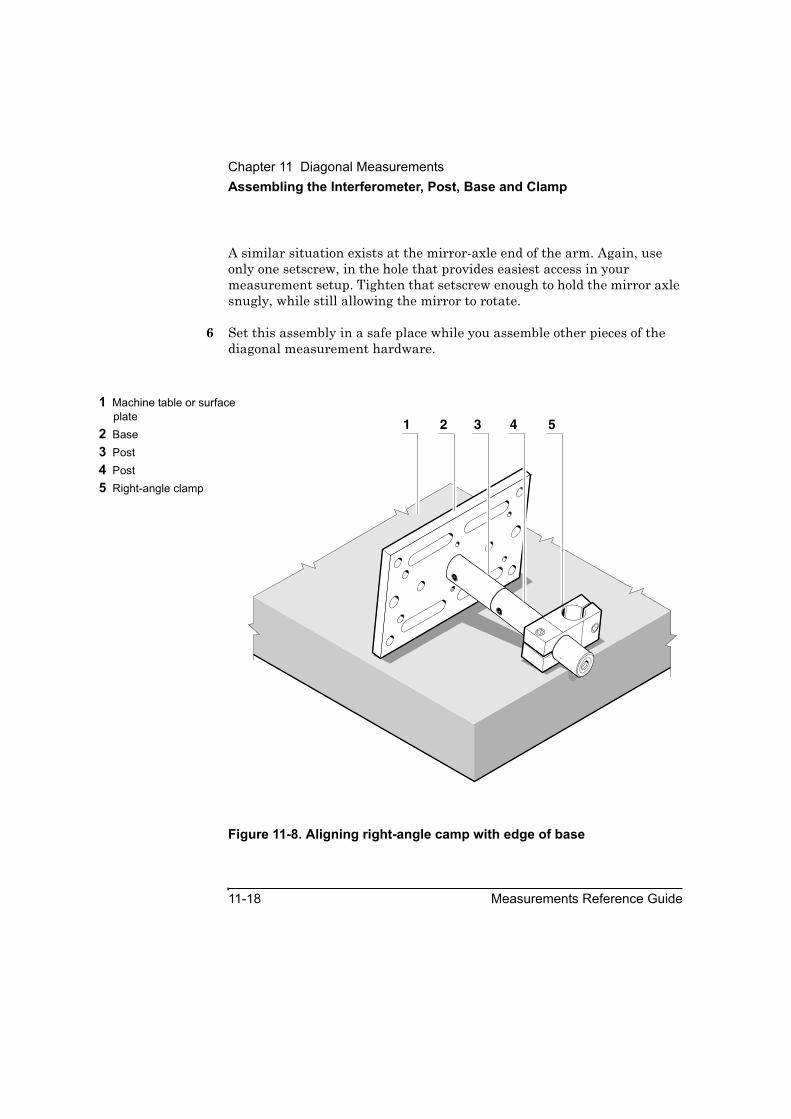
Chapter 11 Diagonal MeasurementsAssembling the Interferometer, Post, Base and Clamp
11-18 Measurements Reference Guide
A similar situation exists at the mirror-axle end of the arm. Again, use only one setscrew, in the hole that provides easiest access in your measurement setup. Tighten that setscrew enough to hold the mirror axle snugly, while still allowing the mirror to rotate.
6 Set this assembly in a safe place while you assemble other pieces of the diagonal measurement hardware.
Figure 11-8. Aligning right-angle camp with edge of base
1 Machine table or surface plate
2 Base3 Post4 Post5 Right-angle clamp
1 2 3 4 5

Chapter 11 Diagonal MeasurementsAssembling the Measurement Retroreflector and Ball-Joint
Measurements Reference Guide 11-19
Assembling the Measurement Retroreflector and Ball-JointUse the instructions below for the retroreflector you choose to use for your diagonal measurement. Refer to Figure 11-9 for these procedures.
Agilent 10767A Linear Retroreflector1 Remove any knurled-knob screw from the Agilent 10767A retroreflector.
2 Place the adapter plate over the back of the retroreflector so the countersunk holes are lined up with the retroreflector holes whose threads are most easily seen.
3 Use two M3× 0.5× 16 flathead screws to fasten the retroreflector to the adapter.
4 Screw the adapter plate onto one of the threaded ends of the ball-joint assembly. Tighten this connection securely, by hand.
5 Set this assembly in a safe place until you install it on the machine.
Agilent 10767B Lightweight Retroreflector1 Fasten the Agilent 10767B retroreflector on the ball-joint, using an
Agilent 10767-20203 Clamp Nut.
2 Set this assembly in a safe place until you install it on the machine.

Chapter 11 Diagonal MeasurementsAssembling the Measurement Retroreflector and Ball-Joint
11-20 Measurements Reference Guide
Figure 11-9. Assembling measurement retroreflector and ball-joint
1 Adapter plate2 Countersunk holes3 Center hole—threaded
M104 Threaded holes—M35 Ball-joint assembly6 Flathead screw—
M3× 0.5× 167 Agilent 10767A linear
retroreflector8 Laser beam from
interferometer9 Nodal point10 Agilent 10767B
lightweight retroreflector11 Center line of spindle
axis12 Clamp nut
2 43
4 2
1
7 8
5
10
12
8
9
11
1
5
6
6

Chapter 11 Diagonal MeasurementsInstalling and Aligning the Optics on the Machine
Measurements Reference Guide 11-21
Installing and Aligning the Optics on the MachineAll machines and measurement situations are not the same. Use the instructions here as a guide to help you in your specific application. Making notes and diagrams of how you set up the measurement hardware can help you or someone else make identical setups on the same machine or a similar one in the future, or can resolve any doubt about exactly what you did.
The procedure given here can be used for either “near low to far high” or “far low to near high” measurements. It aligns the laser measurement beam to the programmed path actually traversed by the machine, such as a body diagonal of the work zone volume. This technique allows you to save and reuse the machine control program for future calibrations. If you had to align the machine to the laser beam, you could not easily reuse the same program, and you could not repeat the same measurement; repeating the same measurement provides a valuable comparison for assessing changes in machine performance.
The general procedure has these major steps:
1. Installing the measurement optics on the machine.
2. Installing and initially aligning the laser head.
3. Aligning the beam to the XY plane diagonal (azimuth angle, α) of the measurement.
4. Aligning the beam to the elevation angle (β) of the measurement.
Chapter 11 Diagonal MeasurementsInstalling and Aligning the Optics on the Machine
11-22 Measurements Reference Guide
Installing the measurement optics on the machineThis procedure is for a stacked-stage milling machine; that is, one whose table can move in X and Y. Adapt the procedure as necessary when you want to use some other setup.
This procedure assumes that you have performed the assembly procedures earlier in this guide.
This procedure has these major steps:
1 Mounting the interferometer assembly on the machine table.
2 Installing the measurement retroreflector.
Mounting the interferometer assembly on the machine tableTo mount the interferometer assembly on the machine, follow these steps:
1 Turn on the PC and start the Agilent 5530 software running.
2 On the Main Menu, select Other Meas.
The Other Measurements screen (Figure 11-10) is displayed.
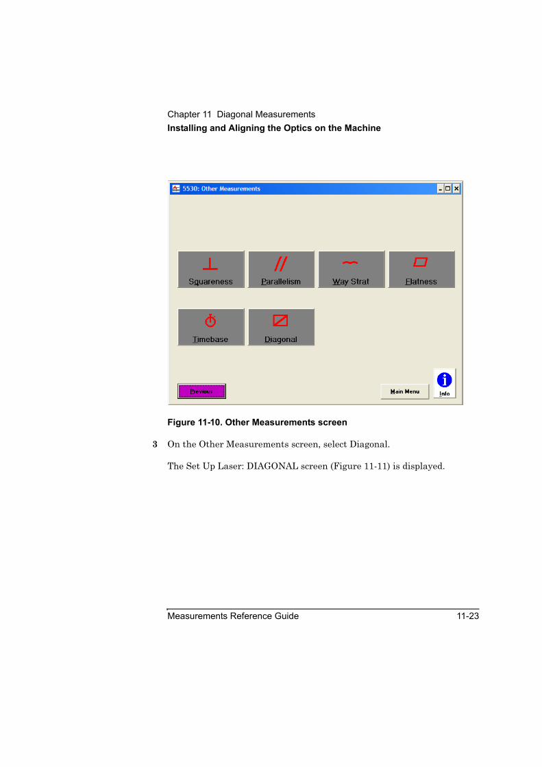
Chapter 11 Diagonal MeasurementsInstalling and Aligning the Optics on the Machine
Measurements Reference Guide 11-23
Figure 11-10. Other Measurements screen
3 On the Other Measurements screen, select Diagonal.
The Set Up Laser: DIAGONAL screen (Figure 11-11) is displayed.
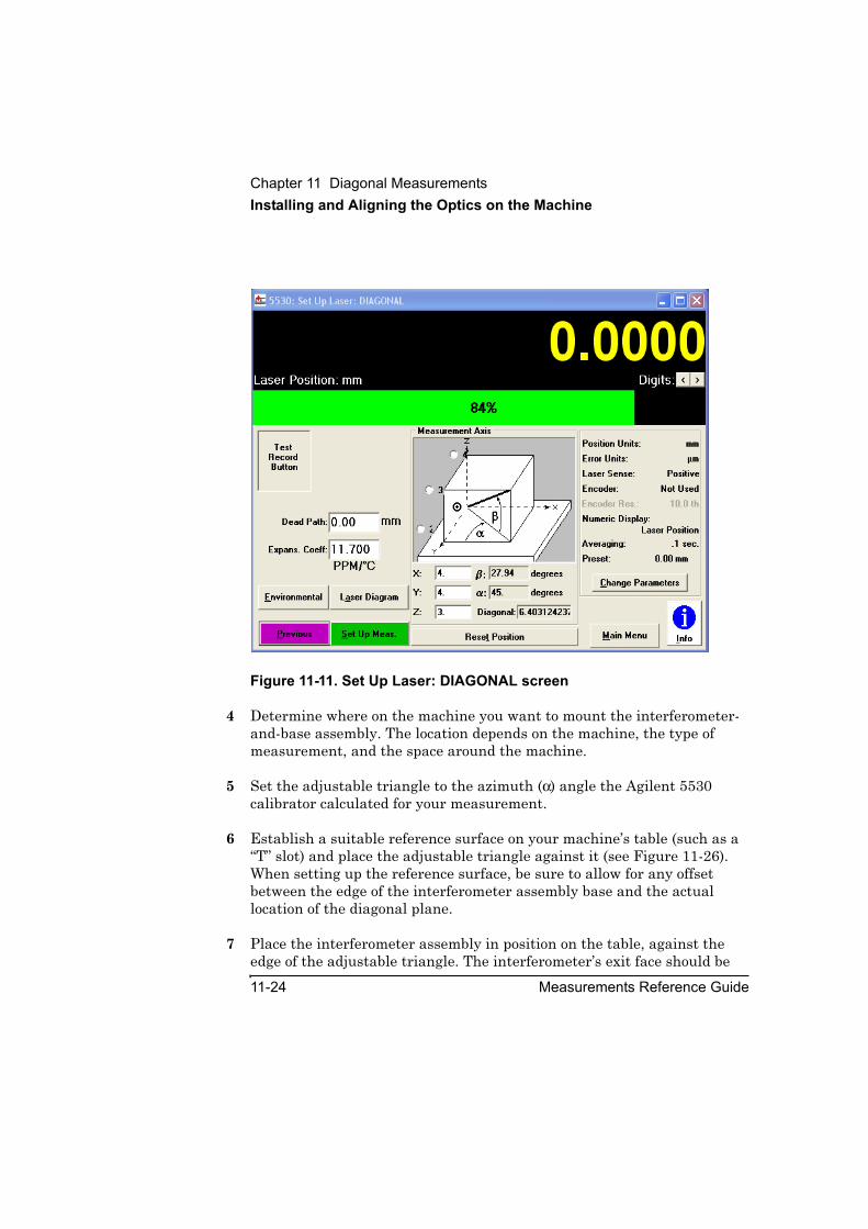
Chapter 11 Diagonal MeasurementsInstalling and Aligning the Optics on the Machine
11-24 Measurements Reference Guide
Figure 11-11. Set Up Laser: DIAGONAL screen
4 Determine where on the machine you want to mount the interferometer-and-base assembly. The location depends on the machine, the type of measurement, and the space around the machine.
5 Set the adjustable triangle to the azimuth (α) angle the Agilent 5530 calibrator calculated for your measurement.
6 Establish a suitable reference surface on your machine’s table (such as a “T” slot) and place the adjustable triangle against it (see Figure 11-26). When setting up the reference surface, be sure to allow for any offset between the edge of the interferometer assembly base and the actual location of the diagonal plane.
7 Place the interferometer assembly in position on the table, against the edge of the adjustable triangle. The interferometer’s exit face should be

Chapter 11 Diagonal MeasurementsInstalling and Aligning the Optics on the Machine
Measurements Reference Guide 11-25
pointing along the XY-plane diagonal of your measurement.
8 Carefully clamp the interferometer assembly base to the machine table.
9 Set the adjustable triangle to the elevation angle (β) the Agilent 5530 calibrator calculated for the body diagonal you are measuring.
10 Use the adjustable triangle to set the initial elevation angle of the interferometer assembly and beam steering arm (see Figure 11-27). For a coarser alignment, you can simply use the scale on the side of the beam steering arm assembly.
11 Set the adjustable triangle for 90 degrees.
12 Use the adjustable triangle against the table or the interferometer assembly base and the back of the beam steering mirror tray to set the beam steering mirror vertical.
13 Adjust the knob on the back of the beam steering mirror tray to set the mirror in its neutral position. The pointer on the knob should be in line with the mark on the tray.
You will refine these initial adjustments in the procedures below.
Installing the measurement retroreflectorThe measurement retroreflector is a cube corner having the property of redirecting an input beam back toward its source along a parallel line. Exact orientation of the retroreflector is not critical. This procedure assumes that you have already assembled the measurement retroreflector and ball-joint as described earlier.
1 If necessary, remove any tool in the spindle.
2 Insert the free end of the ball-joint assembly into the spindle and tighten it in place.
3 Point the measurement retroreflector’s face toward the interferometer’s measurement face, align the retroreflector so these faces are parallel, then tighten the ball-joint screw to hold this alignment.
Chapter 11 Diagonal MeasurementsInstalling and Aligning the Optics on the Machine
11-26 Measurements Reference Guide
NOTE You can slightly reduce the sensitivity of the measurement retroreflector to rotational motions of the spindle by placing the retroreflector’s nodal point on the spindle’s axis. In either retroreflector described here, the nodal point is about 12.6 mm (0.5 inch) behind the front surface of the glass. (See Figure 11-9.)
Installing and initially aligning the laser headUse this procedure to install the laser head on the tripod and perform the initial alignment of the laser beam to the XY plane face diagonal of the measurement and parallel to the XY plane (table) of the machine. This alignment is important during measurement as the table carrying the interferometer moves.
1 Place the tripod at the desired point for your measurement. The vertical center line of the tripod should be in or near the vertical plane containing the body diagonal you will be measuring. For this autoreflection alignment procedure, the longer the distance from the laser head to the interferometer, the more accurate the alignment can be; the ideal distance is from 1 to 4 meters (3 to 12 feet).
2 Set the laser head on the tripod and secure it. Refer to the Agilent 5530 Getting Started Guide for details.
3 Connect the laser to its power source and turn it on.
4 Select the laser head’s small output (upper) aperture, and the lower (return port) target, for alignment.
5 Adjust the laser head’s and tripod’s vertical and horizontal translation and pitch and yaw controls so the laser beam autoreflects from the beam steering mirror back to the laser head’s output (upper) port.
NOTE Never stare directly into the laser beam or any bright reflection of it. Failure to observe this warning may result in personal injury.
Chapter 11 Diagonal MeasurementsInstalling and Aligning the Optics on the Machine
Measurements Reference Guide 11-27
6 Place the Agilent 10767-67001 alignment target (shown in Figure 11-2A), with its hole up, over the front of the beam steering mirror. The front of the mirror tray has recesses that enable it to hold the target.
7 Adjust the tripod and laser head positioning controls so the beam autoreflects from the beam steering mirror back to the laser head’s output (upper) port, through the hole in the target.
8 Remove the alignment target from the beam steering mirror.
This completes the installation and initial alignment of the laser head.
Aligning the beam to the XY plane diagonal (azimuth angle, α) of the measurementUse this procedure to improve laser beam alignment along the XY plane face diagonal.
In this procedure, you move a cube corner—in this case, the reference retroreflector attached to the interferometer—along the XY plane face diagonal and check for drifting of the return beam at the laser head.
To perform this procedure:
1 Move the machine to place the interferometer assembly as close to the laser head as possible, without moving the laser head.
NOTE Do not use the mirror tilt adjustment knob on the bottom of the mirror tray until instructed to do so.
2 Rotate (pitch) the beam steering mirror so beam enters the interferometer perpendicular to its input face. The return beam from the reference retroreflector will produce a dot on the face of the laser head near the return (lower) port.
NOTE An alternate procedure that may be easier here is to use a rubber band to hold a small gage block to the input face of the interferometer and use autoreflection back through the beam steering mirror to the laser head input port. Be sure to remove the gage block when done.

Chapter 11 Diagonal MeasurementsInstalling and Aligning the Optics on the Machine
11-28 Measurements Reference Guide
3 Observe the return beam dot on the laser head’s lower (return) port as you move the machine’s table to increase the distance between interferometer and the laser head along the XY plane diagonal of the measurement. Continue moving the interferometer until you do not see the dot or until the end of travel is reached, whichever occurs first. If you lose sight of the dot before end of travel is reached, return the interferometer to the last position at which you saw the dot.
If the dot drifts as the interferometer moves, the laser beam is not perfectly aligned to the travel path. The remainder of this procedure corrects that alignment.
4 With the interferometer at its farthest travel point or at the last point at which a return dot was visible, yaw and pitch (turn and tilt) the laser head on the tripod as necessary to center the return beam on the lower port. You may speed your alignment procedure by doing some overcorrection, moving the dot to the other side of the lower port; experience will help you here.
5 Observe the return beam spot on the laser head’s face as you use the machine to move the interferometer toward the laser head.
6 If the return beam spot moves, translate the laser head horizontally and vertically, without turning it, so most or all of the return beam from the interferometer will enter the lower port. Do not overcorrect on your translation adjustments.
7 Repeat steps 3 through 7 until the return beam from the interferometer can enter the laser head’s lower port at all interferometer positions along the XY plane diagonal.
Now your setup is ready for aligning to the actual measurement (body) diagonal. Do not make any more changes to the laser head or tripod position controls until instructed to do so.

Chapter 11 Diagonal MeasurementsInstalling and Aligning the Optics on the Machine
Measurements Reference Guide 11-29
Aligning the beam to the elevation angle (β) of the measurementThis procedure assumes that you have performed the assembly, installation, and alignment procedures above. This means that the laser head has already been aligned to the XY diagonal (azimuth) path of your measurement, and you should only need to adjust the beam steering mirror to direct the beam toward the measurement retroreflector moving along the measurement diagonal.
It is likely that, no matter how precise you have tried to be in your setup, you will have to make some alignment adjustments. Here, previous experience performing distance (linear) alignments can be a help as you align the optics.
1 Move the machine spindle and table to place the measurement retroreflector close to the output face of the interferometer.
2 Adjust the measurement retroreflector so its face is parallel to and centered on the interferometer’s measurement face (the one facing along the measurement path).
3 At this time, the measurement retroreflector should be providing a return beam to the front of the laser head. If the return beams from the two retroreflectors overlap, you will see only one dot.
NOTE You may have to reposition the measurement retroreflector slightly in order to overlap the measurement beam dot and reference beam dot on the laser head’s input port.
NOTE If you want to see only the dot from the measurement path return beam, remove the reference retroreflector from the interferometer, being careful not to disturb the interferometer alignment. Be sure to replace this retroreflector before you try to make a measurement.
Another way to identify the measurement beam dot during alignment is to use your hand to momentarily interrupt the measurement path beam.

Chapter 11 Diagonal MeasurementsInstalling and Aligning the Optics on the Machine
11-30 Measurements Reference Guide
4 Observe the measurement beam dot as you move the machine to increase the distance between the interferometer and the measurement retroreflector along the body diagonal.
Continue moving the interferometer and measurement retroreflector until the moving dot disappears or until the end of travel is reached, whichever occurs first. If the dot disappears before end of travel is reached, return the interferometer to the last position at which you saw the dot.
Movement of the measurement beam dot indicates that the measurement beam was not perfectly aligned to the work zone body diagonal. If the dot moves, perform steps 5 through 9 below.
5 Slightly rotate the beam steering mirror to move the measurement return dot back to the laser head’s return port. You may also have to make a slight adjustment of the knob on the bottom of the mirror tray to do this.
6 Move the machine to return the measurement retroreflector and the interferometer to their close-together position.
7 If necessary, reposition the measurement retroreflector so its return dot overlaps the dot from the reference retroreflector attached to the interferometer. (If you removed the reference retroreflector earlier, you should re-attach it now.)
8 If necessary, slightly translate the laser head, without turning it, so the overlapping dots are over its lower (return) port.
9 Repeat steps 3 through 9 to verify satisfactory alignment, indicated by both dots remaining stationary on the laser head’s return port as the measurement optics are moved through the entire measurement travel range.
10 When the alignment is satisfactory:
a. Tighten all adjustment locks to keep settings from changing.
b. Repeat steps 3 through 8, to be sure nothing has changed.

Chapter 11 Diagonal MeasurementsMaking Your Measurement
Measurements Reference Guide 11-31
Making Your MeasurementGuide: This information relates to flowchart items 7 through 10 inFigure 11-1.
1 After you have finished aligning the measurement optics to the diagonal path to be measured, select Set Up Meas on the Agilent 5530’s Set Up Laser: DIAGONAL screen.
The Set Up Measurement: DIAGONAL screen (Figure 11-12) is displayed.
Figure 11-12. Set Up Measurement: DIAGONAL screen
2 Make any changes to the setup required for your situation, then press Collect Data.

Chapter 11 Diagonal MeasurementsMaking Your Measurement
11-32 Measurements Reference Guide
At its simplest, a diagonal measurement is a linear distance measurement along a line that is not necessarily parallel to nor perpendicular to one or more of the machine’s major axes (X, Y, or Z). As such, a diagonal measurement is subject to the same accuracy problems as any other laser linear distance measurement. For more information about this, read the appropriate information in your measurement system documentation. In particular, see the discussion of cosine error.
3 In the absence of any special instructions, record and save your diagonal measurement data in the same way you take your linear distance measurement data.
After the Agilent 5530 calibrator has finished collecting the required data, it will automatically switch to the Analyze Data: DIAGONAL screen shown in Figure 11-13.
Figure 11-13. Analyze Data: DIAGONAL screen (following Collect Data Window)
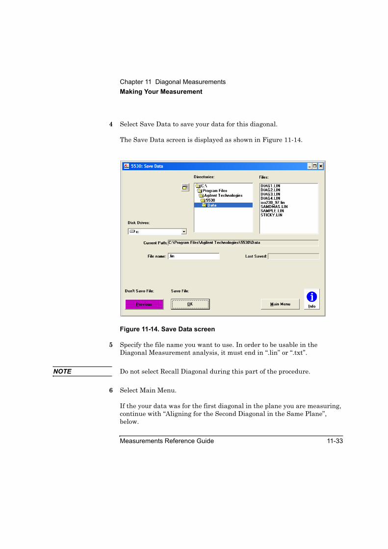
Chapter 11 Diagonal MeasurementsMaking Your Measurement
Measurements Reference Guide 11-33
4 Select Save Data to save your data for this diagonal.
The Save Data screen is displayed as shown in Figure 11-14.
Figure 11-14. Save Data screen
5 Specify the file name you want to use. In order to be usable in the Diagonal Measurement analysis, it must end in “.lin” or “.txt”.
NOTE Do not select Recall Diagonal during this part of the procedure.
6 Select Main Menu.
If the your data was for the first diagonal in the plane you are measuring, continue with “Aligning for the Second Diagonal in the Same Plane”, below.
Chapter 11 Diagonal MeasurementsAligning for the Second Diagonal in the Same Plane
11-34 Measurements Reference Guide
If your data was for the second diagonal in the first plane, you will have to move the laser head and begin the alignment procedure for the second plane. Go back to “Installing the measurement optics on the machine” text. Note that you must not change the measurement setup values from those of the previous measurements you have made for this diagonal analysis.
If your data was for the fourth diagonal to be used in your analysis, go to “Analyzing your data” below.
Aligning for the Second Diagonal in the Same PlaneAlignment to the “far low to near high” diagonal in this plane is similar to the procedure above for the first diagonal (“near low to far high”).
NOTE Do not move the laser head. The beam is already aligned for the second diagonal.
The difference is:
• The interferometer assembly is moved to the position on the table where it intersects the second diagonal; that is, the opposite end of the diagonal plane of the work zone being calibrated.
• The interferometer and beam steering mirror angles must be reset as required for the new measurement. Again, you can use the adjustable triangle to provide a more accurate initial setup. Refer to Figures 11-5 through 11-7 to determine what might be the best setup for your second-diagonal measurement.
• The measurement retroreflector must be reoriented, to return the measurement beam to the interferometer in its new location.

Chapter 11 Diagonal MeasurementsAnalyzing your data
Measurements Reference Guide 11-35
Analyzing your dataGuide: This information relates to flowchart items 12 through 14 in Figure 11-1.
If you are not already at the Agilent 5530 calibrator’s (or Metrology) Main Menu, open that screen (Figure 11-15).
Figure 11-15. Metrology Main Menu
7 Select Recall Data
The Recall Data screen (Figure 11-16) is displayed.

Chapter 11 Diagonal MeasurementsAnalyzing your data
11-36 Measurements Reference Guide
Figure 11-16. Recall Data screen
8 In the Data File Type box, select “Diag (4 *.lin)” to recall diagonal data.
A screen similar to Figure 11-17A is displayed.
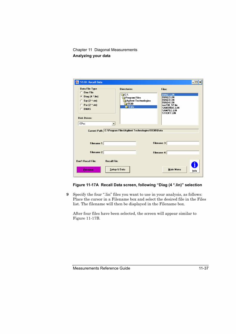
Chapter 11 Diagonal MeasurementsAnalyzing your data
Measurements Reference Guide 11-37
Figure 11-17A Recall Data screen, following “Diag (4 *.lin)” selection
9 Specify the four “.lin” files you want to use in your analysis, as follows: Place the cursor in a Filename box and select the desired file in the Files list. The filename will then be displayed in the Filename box.
After four files have been selected, the screen will appear similar to Figure 11-17B.

Chapter 11 Diagonal MeasurementsAnalyzing your data
11-38 Measurements Reference Guide
Figure 11-17B. Recall Data screen specifying four DIAGn.LIN files
10 Select Setup & Data.
The Analyze Data: DIAGONAL screen, showing the data from the four files you have selected, is displayed as shown in Figure 11-18.

Chapter 11 Diagonal MeasurementsSlant-Bed Lathe
Measurements Reference Guide 11-39
Figure 11-18. Analyze Data: DIAGONAL screen (following Recall Data)
Slant-Bed LatheGuide: This information relates to flowchart item 15 in Figure 11-1.
The Agilent 10768A kit optics can also be used to calibrate a slant-bed lathe without tilting the laser head.
The Agilent 10768-60201 Beam Steering Mirror Assembly that was developed for the Diagonal Measurement application is used to simplify the setup for measurements on a slant-bed lathe. (Slant-bed lathes can also be measured with the Agilent 10769A Beam Steering Mirror, which provides the beam steering assembly and some additional mounting hardware.)
Figures 11-19 and 11-20 show the slant-bed setup.
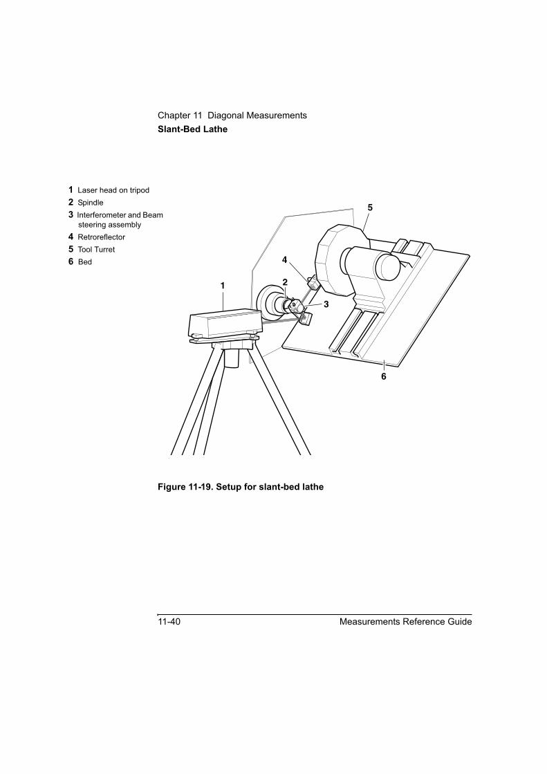
Chapter 11 Diagonal MeasurementsSlant-Bed Lathe
11-40 Measurements Reference Guide
Figure 11-19. Setup for slant-bed lathe
1 Laser head on tripod2 Spindle3 Interferometer and Beam
steering assembly4 Retroreflector5 Tool Turret6 Bed
1 2
5
6
4
3
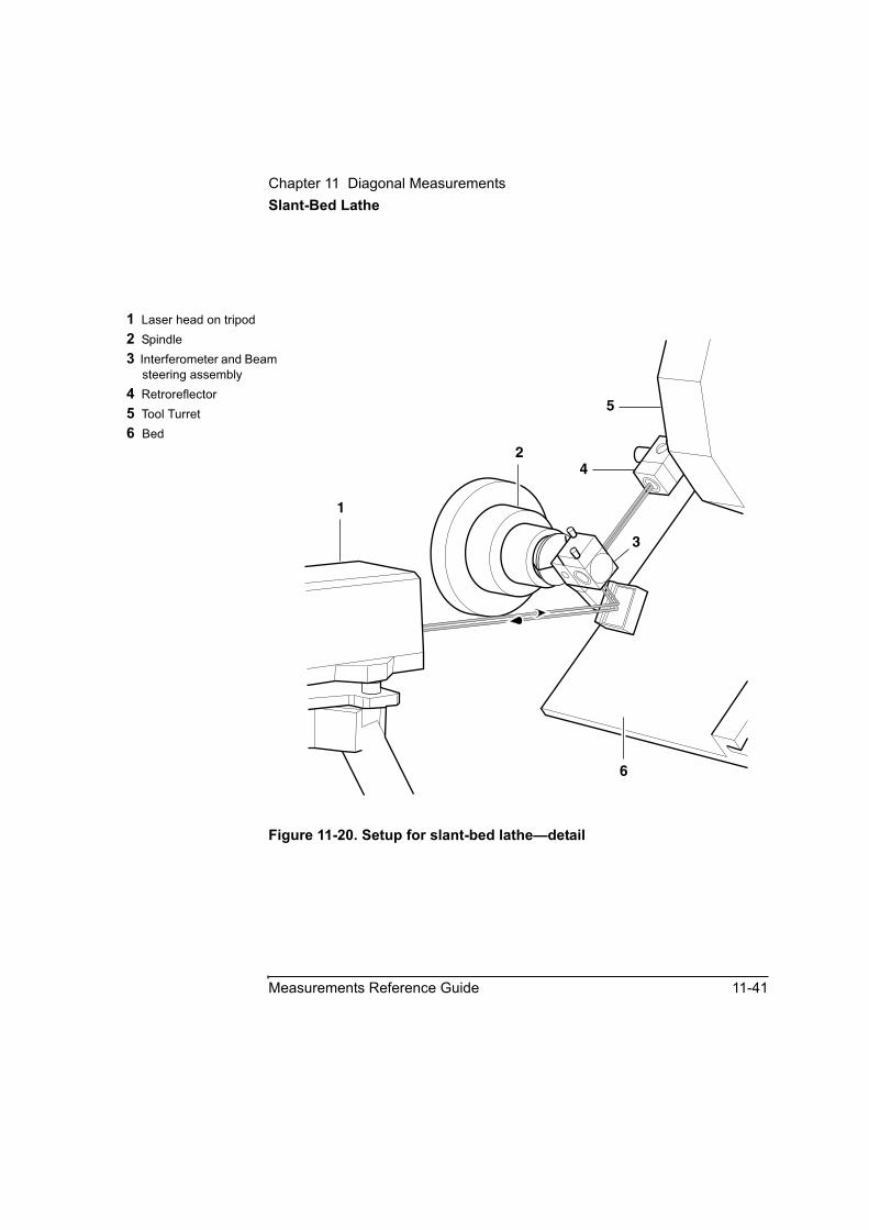
Chapter 11 Diagonal MeasurementsSlant-Bed Lathe
Measurements Reference Guide 11-41
Figure 11-20. Setup for slant-bed lathe—detail
1 Laser head on tripod2 Spindle3 Interferometer and Beam
steering assembly4 Retroreflector5 Tool Turret6 Bed
2
5
6
4
3
1
Chapter 11 Diagonal MeasurementsBasics
11-42 Measurements Reference Guide
Basics• The interferometer has three configurations (see Figure 11-10).
Configurations are named for the direction in which the beam from the laser head is bent, when viewed as shown.
• Laser beams enter and leave the interferometer perpendicular to its faces.
• The beam steering assembly allows a range of (elevation) angles between the laser head and the interferometer (see Figure 11-9). The minimum angle is just before the corner of the interferometer clips the beam between the laser head and the steering mirror. The maximum angle is just before the mirror no longer reflects enough of the beam to enable a measurement. Note that the angles shown in Figures 11-22 through 11-24 are only those between the interferometer and the incoming laser beam; the allowable measurement elevation angle can be anywhere from 0 to 180 degrees with respect to a horizontal plane, however, no single interferometer configuration allows the beam to be used throughout this range (see Figures 11-5 through 11-7, and Table 11-1).
• Two beam paths are involved in the interferometer’s measurement arm—the beam from the laser head and the beam returned to the receiver in the laser head.
• Whenever a measurement configuration (typically, a “far low to near high” general configuration) directs the measurement path back toward the laser head, the relationship of the two beams is inverted from that normally occurring at the interferometer (see Figure 11-25). Keeping this in mind can help you understand and use alignment procedures.
• For procedures in this chapter, azimuth angles (angles on the XY (horizontal plane) are measured with respect to the X-axis or a line parallel to it (see Figure 11-4 or 11-26).
• Elevation angles (measured in the vertical plane containing the diagonals) are measured with respect to the XY plane or a plane parallel to it. (See Figure 11-4 or 11-27.) The maximum elevation angle for any measurement type is 90 degrees. The minimum

Chapter 11 Diagonal MeasurementsBasics
Measurements Reference Guide 11-43
elevation angle is 0 degrees. When the elevation angle has crossed through either 90 or 0 degrees, the measurement configuration has changed; see Figures 11-5 through 11-7.
• When using the adjustable triangle for alignment, you can use secondary references as required. For example, if the azimuth angle is less than 45 degrees, you can use the Y-axis as the reference. (See Figure 11-26.)
• In general, aligning the laser beam for a body diagonal measurement is the same as aligning the beam for any other linear (distance) measurement, except—you have one more optical element, and the diagonal path doesn’t provide a reference surface that allows you to use true square for initial autoreflection alignment before placing the measurement optics. Thus, you must move the optics on the machine along the diagonal path to achieve final alignment.
• A pair of body diagonals is contained in a single vertical plane. The four body diagonals are contained in a pair of intersecting vertical planes.
• The laser beam must be aligned in the vertical plane containing the body diagonal(s) you are measuring (or in a plan parallel to it).
• The interferometer and beam steering assembly may be at either end of a diagonal path.
• The laser head may be to the left or right of the interferometer, when viewed from the side.
• Measurements and measurement setups in this chapter are identified in terms of the end points of the diagonal involved. The first term identifies the interferometer’s position, the second term identifies the measurement retroreflector’s position at the opposite end of the diagonal. “Near” and “far,” refer to end points of the body diagonals in relation to the laser head’s physical position. “Low” and “high” refer to the end points of a body diagonal in relation to each other.
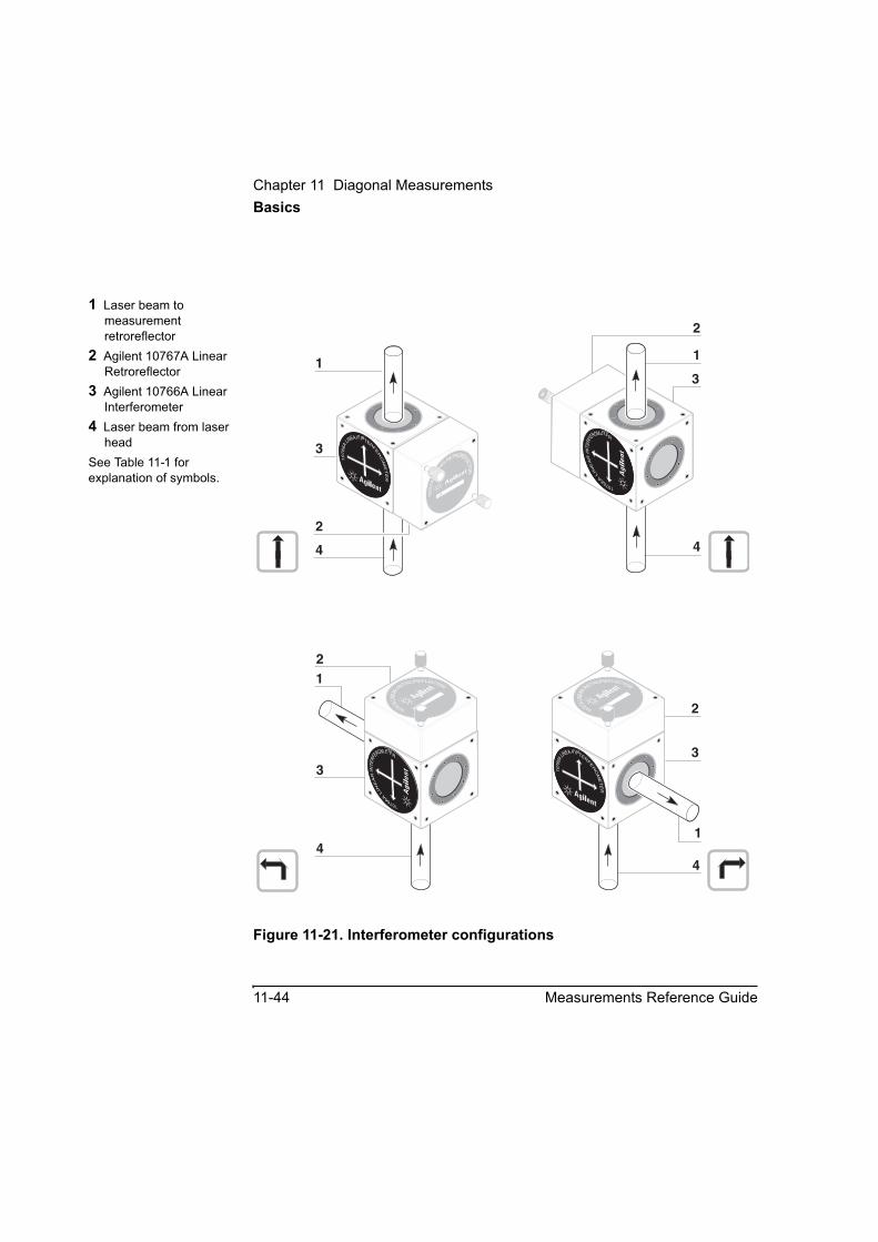
Chapter 11 Diagonal MeasurementsBasics
11-44 Measurements Reference Guide
Figure 11-21. Interferometer configurations
1 Laser beam to measurement retroreflector
2 Agilent 10767A Linear Retroreflector
3 Agilent 10766A Linear Interferometer
4 Laser beam from laser head
See Table 11-1 for explanation of symbols.
1076
6A
LIN
EA
RIN
TE
RFEROMETER
HEWLETT
-PA
CK
AR
D
1076
7A
LIN
EAR
RETROREFLECTOR
H E W L E T T - P AC
K
AR
D
1A1A
1076
6A
LIN
EA
RIN
TE
RFEROMETER
HEWLETT
-PA
CK
AR
D
1
2
3
4
1
3
4
21
3
4
2
3
1
4
10767ALIN
EARRETROREFLECTOR
1A
1076
6ALINEAR INTER
FE
RO
ME
TE
R
10767ALIN
EARRETROREFLECTOR
1A
1076
6ALINEAR INTER
FE
RO
ME
TE
R
1076
7A
LIN
EAR
RETROREFLECTOR
1A
2
10766
A
LIN
EA
RIN
TE
RFEROMETER
10766
A
LIN
EA
RIN
TE
RFEROMETER
10
766
ALIN
EAR INTERFE
RO
ME
TE
R
1076
6ALINEAR INTER
FE
RO
ME
TE
R
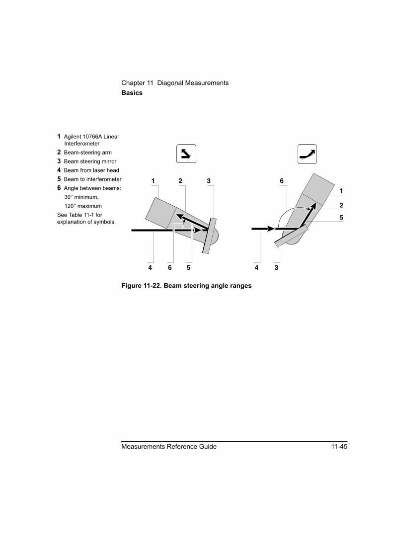
Chapter 11 Diagonal MeasurementsBasics
Measurements Reference Guide 11-45
Figure 11-22. Beam steering angle ranges
1 Agilent 10766A Linear Interferometer
2 Beam-steering arm3 Beam steering mirror4 Beam from laser head5 Beam to interferometer6 Angle between beams:
30° minimum, 120° maximum
See Table 11-1 for explanation of symbols.
1 2
1
3
2
4 34
6
5
6 5
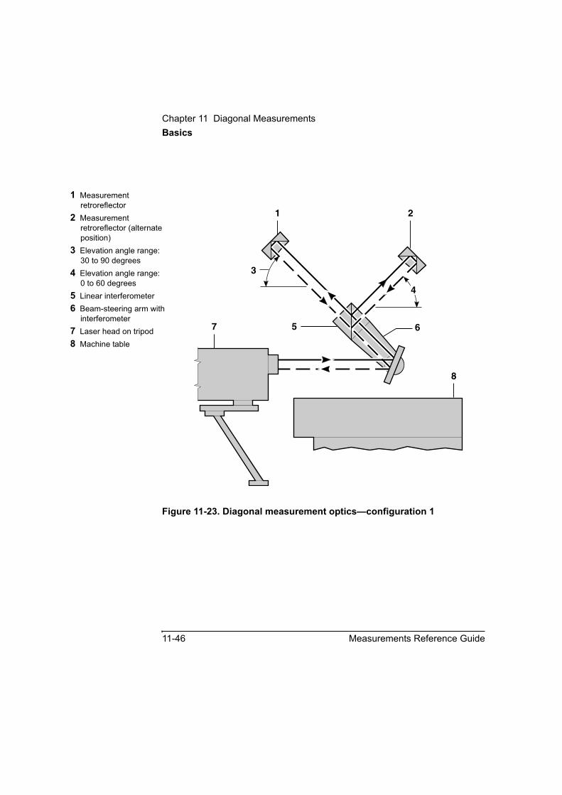
Chapter 11 Diagonal MeasurementsBasics
11-46 Measurements Reference Guide
Figure 11-23. Diagonal measurement optics—configuration 1
1 Measurement retroreflector
2 Measurement retroreflector (alternate position)
3 Elevation angle range:30 to 90 degrees
4 Elevation angle range:0 to 60 degrees
5 Linear interferometer6 Beam-steering arm with
interferometer7 Laser head on tripod8 Machine table
6
8
7 5
3
4
1 2

Chapter 11 Diagonal MeasurementsBasics
Measurements Reference Guide 11-47
Figure 11-24. Diagonal measurement optics—configuration 2
1 Measurement retroreflector
2 Measurement retroreflector (alternate position)
3 Elevation angle range:30 to 90 degrees
4 Elevation angle range:0 to 60 degrees
5 Linear interferometer6 Beam-steering arm with
interferometer7 Laser head on tripod8 Machine table
1
2
6
8
753
4

Chapter 11 Diagonal MeasurementsBasics
11-48 Measurements Reference Guide
Figure 11-25. Two beams
1 Measurement retroreflector
2 Return beam to laser head
3 Outgoing beam from laser head
4 Beam-steering arm assembly with interferometer
5 Laser headSee Table 11-1 for explanation of symbols.
1
5 4
231
5 4
2 3
1076
6ALI
NEAR INTERFERO
METE
R
1076
6ALI
NEAR INTERFERO
METE
R

Chapter 11 Diagonal MeasurementsBasics
Measurements Reference Guide 11-49
Figure 11-26. Setting the XY plane diagonal angle using the adjustable triangle
1 Laser beam along diagonal plane
2 Machine table top3 Base4 Y-axis or parallel line on
machine table top5 Laser Head6 Adjustable triangle7 X-axis or parallel line on
machine table top
2
4
5
67
45
45
1 3

Chapter 11 Diagonal MeasurementsBasics
11-50 Measurements Reference Guide
Figure 11-27. Setting the elevation angle using the adjustable triangle
1 Adjustable triangle2 Beam steering assembly
with interferometer and reference retroreflector
3 Beam to measurement retroreflector
4 Elevation angle between horizontal plane and beam
5 Horizontal reference plane
6 Beam from laser head
2 3
6 5
1
≤ 45°
4
≥ 45°
≤ 45°
≥ 45°
Chapter 11 Diagonal MeasurementsCharacteristics
Measurements Reference Guide 11-51
CharacteristicsAgilent 10768A Diagonal Measurement Kit and Agilent 10769A Beam-Steering Mirror
Weight: 10768-6020110768-2020710768-6020310768-2021510785-2000510776-2000810768-2021310767-6700110768-20214Agilent 10767B10767-20203
Beam steering assembly: 354 g (12.5 oz)Right angle clamp: 68 g (2.4 oz)Ball-joint assembly: 123 g (4.3 oz)Adapter plate: 36 g (1.3 oz)Post–long: 228 g (8.0 oz)Post–medium: 111 g (3.9 oz)Post–stub: 42 g (1.5 oz)Alignment Target: 11 g (0.39 oz)Base–large: 832 g (29.3 oz)Lightweight retroreflector: 34.7 g (1.2 oz)Clamp Nut (used with Agilent 10767B retroreflector): 4.6 g (0.16 oz)
Mirror: Coating: Hard dielectricClear aperture: central oval 25 mm × 45 mm (1.0 × 1.8 in)Flatness: 1/10 wavelength at 633 nmReflectance: ≥ 90% over incidence range of 0° to 60° at 633 nm (both s and p polarizations)
Adjustable Ball-joint threads: M10 × 1.5, M8 × 1.25
Modes of use: 1. Linear interferometer attached to beam-steering arm assembly for diagonal measurements.
2. Linear interferometer mounted remotely from beam-steering arm assembly for diagonal measurements.
3. Linear interferometer attached to beam-steering arm for slant-bed lathe calibration.
4. Beam-steering arm alone as beam-steering mirror.

Chapter 11 Diagonal MeasurementsCharacteristics
11-52 Measurements Reference Guide

A
Operating Specifications
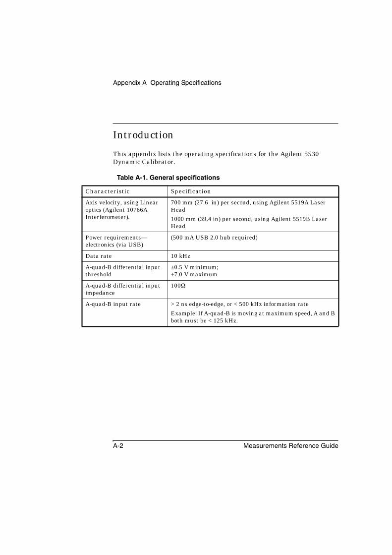
Appendix A Operating Specifications
A-2 Measurements Reference Guide
Introduction
This appendix lists the operating specifications for the Agilent 5530 Dynamic Calibrator.
Table A-1. General specifications
Characteristic Specification
Axis velocity, using Linear optics (Agilent 10766A Interferometer).
700 mm (27.6 in) per second, using Agilent 5519A Laser Head1000 mm (39.4 in) per second, using Agilent 5519B Laser Head
Power requirements—electronics (via USB)
(500 mA USB 2.0 hub required)
Data rate 10 kHz
A-quad-B differential input threshold
±0.5 V minimum;±7.0 V maximum
A-quad-B differential input impedance
100Ω
A-quad-B input rate > 2 ns edge-to-edge, or < 500 kHz information rateExample: If A-quad-B is moving at maximum speed, A and B both must be < 125 kHz.
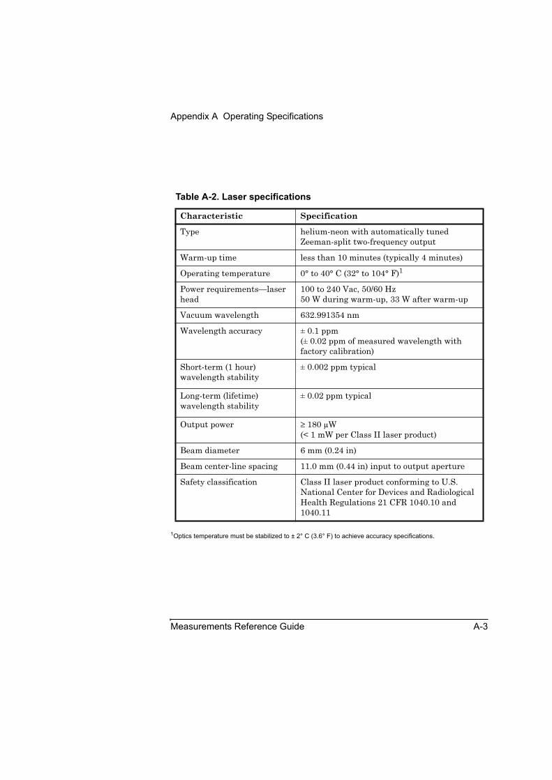
Appendix A Operating Specifications
Measurements Reference Guide A-3
1Optics temperature must be stabilized to ± 2° C (3.6° F) to achieve accuracy specifications.
Table A-2. Laser specifications
Characteristic Specification
Type helium-neon with automatically tuned Zeeman-split two-frequency output
Warm-up time less than 10 minutes (typically 4 minutes)
Operating temperature 0° to 40° C (32° to 104° F)1
Power requirements—laser head
100 to 240 Vac, 50/60 Hz50 W during warm-up, 33 W after warm-up
Vacuum wavelength 632.991354 nm
Wavelength accuracy ± 0.1 ppm(± 0.02 ppm of measured wavelength with factory calibration)
Short-term (1 hour) wavelength stability
± 0.002 ppm typical
Long-term (lifetime) wavelength stability
± 0.02 ppm typical
Output power ≥ 180 μW(< 1 mW per Class II laser product)
Beam diameter 6 mm (0.24 in)
Beam center-line spacing 11.0 mm (0.44 in) input to output aperture
Safety classification Class II laser product conforming to U.S. National Center for Devices and Radiological Health Regulations 21 CFR 1040.10 and 1040.11
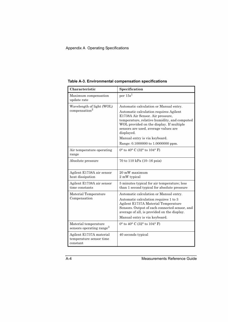
Appendix A Operating Specifications
A-4 Measurements Reference Guide
Table A-3. Environmental compensation specifications
Characteristic Specification
Maximum compensation update rate
per 15s1
Wavelength of light (WOL) compensation2
Automatic calculation or Manual entry.Automatic calculation requires Agilent E1738A Air Sensor. Air pressure, temperature, relative humidity, and computed WOL provided on the display. If multiple sensors are used, average values are displayed.Manual entry is via keyboard.Range: 0.1000000 to 1.0000000 ppm.
Air temperature operating range
0° to 40° C (32° to 104° F)
Absolute pressure 70 to 110 kPa (10–16 psia)
Agilent E1738A air sensor heat dissipation
20 mW maximum2 mW typical
Agilent E1738A air sensor time constants
5 minutes typical for air temperature; less than 1 second typical for absolute pressure
Material Temperature Compensation
Automatic calculation or Manual entry.Automatic calculation requires 1 to 3 Agilent E1737A Material Temperature Sensors. Output of each connected sensor, and average of all, is provided on the display.Manual entry is via keyboard.
Material temperature sensors operating range3
0° to 40° C (32° to 104° F)
Agilent E1737A material temperature sensor time constant
40 seconds typical

Appendix A Operating Specifications
Measurements Reference Guide A-5
1Combined wavelength of light (WOL) and material temperature compensation.
2 WOL compensation is based on the Agilent E1738A Air Sensor.
3 Material temperature compensation is based on the Agilent E1737A Material Temperature sensors
4 Based on a 12-month calibration cycle and taking into account the effects of sensor aging over 12 months.
Agilent E1737A material temperature sensor maximum error4
± 0.1° C (0.18° F) when calibrated
Material Expansion Coefficient:
Range: -100.0 to +100.0 ppm per °C or °F, manually entered.
Table A-3. Environmental compensation specifications (Continued)
Characteristic Specification
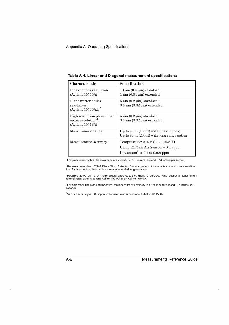
Appendix A Operating Specifications
A-6 Measurements Reference Guide
1For plane mirror optics, the maximum axis velocity is ±350 mm per second (±14 inches per second).
2Requires the Agilent 10724A Plane Mirror Reflector. Since alignment of these optics is much more sensitive than for linear optics, linear optics are recommended for general use.
3Requires the Agilent 10704A retroreflector attached to the Agilent 10705A-C03. Also requires a measurement retroreflector: either a second Agilent 10704A or an Agilent 10767A.
4For high resolution plane mirror optics, the maximum axis velocity is ± 175 mm per second (± 7 inches per second).
5Vacuum accuracy is ± 0.02 ppm if the laser head is calibrated to MIL-STD 45662.
Table A-4. Linear and Diagonal measurement specifications
Characteristic Specification
Linear optics resolution (Agilent 10766A)
10 nm (0.4 μin) standard;1 nm (0.04 μin) extended
Plane mirror optics resolution1
(Agilent 10706A,B2
5 nm (0.2 μin) standard;0.5 nm (0.02 μin) extended
High resolution plane mirror optics resolution4
(Agilent 10716A)2
5 nm (0.2 μin) standard;0.5 nm (0.02 μin) extended
Measurement range Up to 40 m (130 ft) with linear optics;Up to 80 m (260 ft) with long range option
Measurement accuracy Temperature: 0–40° C (32–104° F)Using E1738A Air Sensor: ± 0.4 ppmIn vacuum5: ± 0.1 (± 0.02) ppm
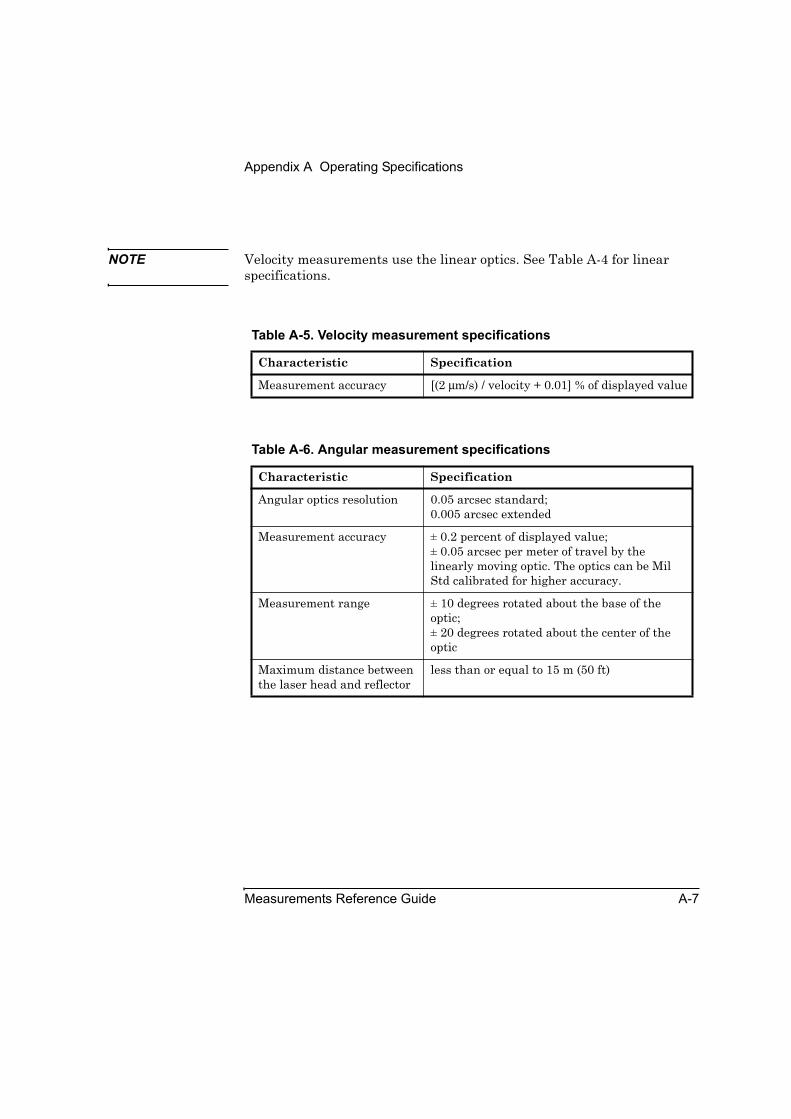
Appendix A Operating Specifications
Measurements Reference Guide A-7
NOTE Velocity measurements use the linear optics. See Table A-4 for linear specifications.
Table A-5. Velocity measurement specifications
Characteristic Specification
Measurement accuracy [(2 μm/s) / velocity + 0.01] % of displayed value
Table A-6. Angular measurement specifications
Characteristic Specification
Angular optics resolution 0.05 arcsec standard;0.005 arcsec extended
Measurement accuracy ± 0.2 percent of displayed value;± 0.05 arcsec per meter of travel by the linearly moving optic. The optics can be Mil Std calibrated for higher accuracy.
Measurement range ± 10 degrees rotated about the base of the optic; ± 20 degrees rotated about the center of the optic
Maximum distance between the laser head and reflector
less than or equal to 15 m (50 ft)

Appendix A Operating Specifications
A-8 Measurements Reference Guide
1Straightness measurement accuracy is analogous to the traditional straightedge and indicator method of measuring straightness.
Optical reference accuracy, listed in Table A-7, corresponds to straightedge accuracy. Optical reference accuracy can be eliminated by using straightedge (mirror) reversal techniques.
Measurement accuracy corresponds to the indicator accuracy. It depends on the optics being used, and the temperature range. See table A-8 or A-9.
2Axial separation is the distance between the interferometer and the reflector with proper alignment and air temperature between 15° and 25° C (59° and 77° F).
Table A-7. Straightness measurement specifications
Characteristic Specification
Straightness measurement range
± 1.5 mm (0.059 in)
Straightness measurement accuracy1
Overall accuracy = Optical reference accuracy + Measurement accuracy
Optical reference accuracy for short range optics1
± 0.15 M2 μm where M is the distance the moving optic has traveled in meters; ± 0.5 F2 μin where F is the distance the moving optic has traveled in feet
Optical reference accuracy for long range optics1
± 0.015 M2 μm where M is the distance the moving optic has traveled in meters; ± 0.05 F2 μin where F is the distance the moving optic has traveled in feet
Straightness measurement resolution for short-range optics
0.01 μm (0.4 μin)
Straightness measurement resolution for long-range optics
0.1 μm (4 μin)
Axial separation2 0.1 to 3 m (4 to 120 in) with short range optics, 1 to 30 m (3 to 100 ft) with long range optics

Appendix A Operating Specifications
Measurements Reference Guide A-9
Table A-8. Straightness measurement accuracy for short range optics
Characteristic Specification
Measurements between 0 and 10 μm (0 to 400 μin)
± 3.5 percent of displayed value at 0 to 40° C (32 to 104° F)
Measurements between 10 and 1,500 μm (400 to 60,000 μin)
±1 percent of displayed value ± 0.25 μm (10 μin) at 0 to 40° C (32 to 104° F)
Table A-9. Straightness measurement accuracy for long range optics
Characteristic Specification
Measurements between 0 and 100 μm (0 to 4000 μin)
± 5 percent of displayed value at 0 to 40° C (32 to 104° F))
Measurements between 100 and 1,500 μm (4000 to 60,000 μin)
± 2.5 percent of displayed value ± 2.5 μm (100 μin) at 0 to 40° C (32 to 104° F)
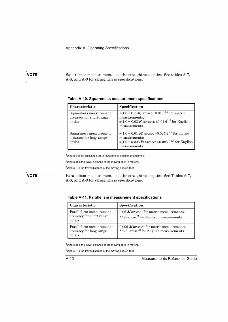
Appendix A Operating Specifications
A-10 Measurements Reference Guide
NOTE Squareness measurements use the straightness optics. See tables A-7,A-8, and A-9 for straightness specifications.
1Where θ is the calculated out-of-squareness angle in arcseconds.
2Where M is the travel distance of the moving optic in meters.
3Where F is the travel distance of the moving optic in feet.
NOTE Parallelism measurements use the straightness optics. See Tables A-7,A-8, and A-9 for straightness specifications.
1Where M is the travel distance of the moving optic in meters.
2Where F is the travel distance of the moving optic in feet.
Table A-10. Squareness measurement specifications
Characteristic Specification
Squareness measurement accuracy for short-range optics
±(1.0 + 0.1 M) arcsec ±0.01 θ1,2 for metric measurements;±(1.0 + 0.03 F) arcsecs ±0.01 θ1,3 for English measurements
Squareness measurement accuracy for long-range optics
±(1.0 + 0.01 M) arcsec ±0.025 θ1,2 for metric measurements;±(1.0 + 0.003 F) arcsecs ±0.025 θ1,3 for English measurements
Table A-11. Parallelism measurement specifications
Characteristic Specification
Parallelism measurement accuracy for short range optics
0.06 M arcsec1 for metric measurements;F/60 arcsec2 for English measurements
Parallelism measurement accuracy for long range optics
0.006 M arcsec1 for metric measurements; F/600 arcsec2 for English measurements
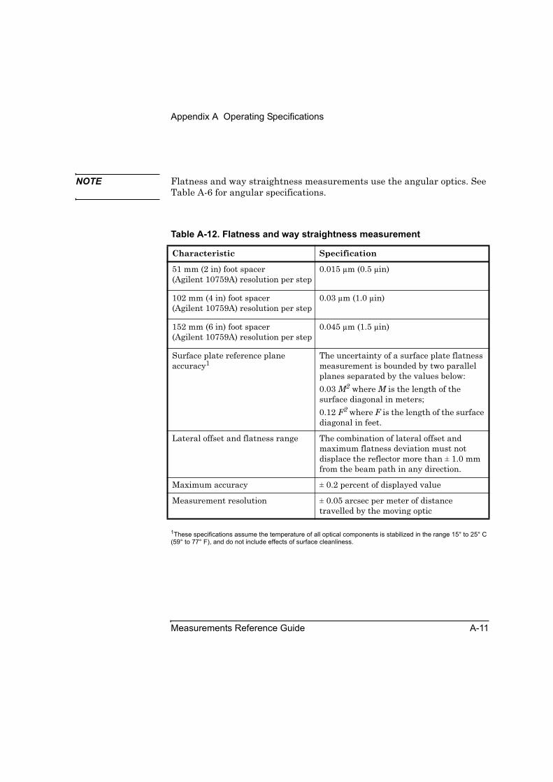
Appendix A Operating Specifications
Measurements Reference Guide A-11
NOTE Flatness and way straightness measurements use the angular optics. See Table A-6 for angular specifications.
1These specifications assume the temperature of all optical components is stabilized in the range 15° to 25° C (59° to 77° F), and do not include effects of surface cleanliness.
Table A-12. Flatness and way straightness measurement
Characteristic Specification
51 mm (2 in) foot spacer (Agilent 10759A) resolution per step
0.015 μm (0.5 μin)
102 mm (4 in) foot spacer (Agilent 10759A) resolution per step
0.03 μm (1.0 μin)
152 mm (6 in) foot spacer (Agilent 10759A) resolution per step
0.045 μm (1.5 μin)
Surface plate reference plane accuracy1
The uncertainty of a surface plate flatness measurement is bounded by two parallel planes separated by the values below:0.03 M2 where M is the length of the surface diagonal in meters;0.12 F2 where F is the length of the surface diagonal in feet.
Lateral offset and flatness range The combination of lateral offset and maximum flatness deviation must not displace the reflector more than ± 1.0 mm from the beam path in any direction.
Maximum accuracy ± 0.2 percent of displayed value
Measurement resolution ± 0.05 arcsec per meter of distance travelled by the moving optic

Appendix A Operating Specifications
A-12 Measurements Reference Guide

Measurements Reference Guide Index-1
IndexAabout this guide, preface, 1-xiiiaccuracy
volumeric, 11-10volumetric, 11-4
Agilent 10744A Accessory Kit, description, 11-8
Agilent 10767A retroreflector, 11-8Agilent 10767B Lightweight
Retroreflector, description, 11-8Agilent 10768A Diagonal Measurement
Kit, description, 11-4Agilent 10768A Diagonal Measurement
Kit, illustrated, 11-6Agilent 10769A Beam Steering
Mirror, 11-8description of, 11-8
Agilent 55290-67001 Replacement Hardware Kit, 4-24
Agilent 55290-67003 Option 744 Hardware Kit, 4-24
Agilent 55290A Angular Position Measurement Kit, 4-24
Agilent 55290A kit, 4-24Agilent 5529A/55292A Option 744
Fixturing Kit, 4-24aligning the laser beam
timebase measurements, 3-7aligning the optics, 3-7Analysis Data: DIAGONAL screen
(following Collect Data Window), illustrated, 11-32
Analyze Data: ANGULAR screen, illustrated, 4-23
Analyze Data: DIAGONAL screen (following Recall Data), illustrated, 11-39
Analyze Data: FLATNESS screen in numeric format, illustrated, 9-40
Analyze Data: FLATNESS screen, illustrated, 9-33
Analyze Data: LINEAR screen, illustrated, 2-29
Analyze Data: SQUARENESS screen, illustrated, 7-12
Analyze Data: STRAIGHTNESS screen, illustrated, 5-28
Analyze Data: TIMEBASE screen, illustrated, 3-13
Analyze Data:SQUARENESS screen, illustrated, 6-23
angluar measurementsinterferometer
attaching the target, illustrated, 4-17
angular measurements, 4-2aligning
laser for long-range measurements, 4-19
laser for short-range measurements, 4-20
optics, 4-16description, 4-2hardware required, 4-3height adjuster, mounting, 4-13interferometer
assembling, 4-10spindle mounting, 4-14
interferometer assemblymounting for pitch
measurements,illustrated, 4-11
mounting for yaw measurements,illustrated, 4-11
reflectorassembling, 4-10table mounting, 4-10
table mounting, 4-10

Index
Index-2 Measurements Reference Guide
mountingoptics, 4-6
mounting reflector for pitch measurements, illustrated, 4-12
mounting reflector for yaw measurements, illustrated, 4-12
opticspositioning for pitch
measurements,illustrated, 4-8
positioning for yaw measurements,illustrated, 4-9
pitch, 4-2precision index table, 4-67preparing for, 4-4programming the machine to be
calibrated, 4-32required hardware, 4-3required optics and hardware for
angular (pitch or yaw) measurements, 4-3
setting Pitch measurement, 4-4setting up, 4-4yaw, 4-2Yaw measurement, 4-4
angular offset, 4-24angular position measurement(s)
clutch breakaway-nut, 4-71clutch, maintenance, 4-68control link, creating, 4-45explained, 4-24fixed optic, mounting, 4-54fixture, 4-68kit ordering, 4-24maintenance
clutchdisassembly, 4-68
mounting and aligning the precision index table on the target machine, 4-37
moveable optic, 4-42parallel spindle and table axes, 4-47
principles of operation, 4-25procedure, 4-31programming the machine to be
calibrated, 4-32storing hardware, 4-67
angular position measurementsmounting and aligning on a
machining center, 4-39setup of computer and laser head,
initial, 4-35ANSI standard B5.54, 11-2ANSI/ASME standards, 11-4azimuth angle, 11-21, 11-27
Bball-joint, 11-19beam steering arm, assembly, 11-12body diagonals, 11-4
Ccalculating angles, diagonal
measurements, 11-11calibration program
planning, 1-4storing, 1-4
clutch, 4-68clutch washer
cleaning, 4-68replacement, 4-70
Collect Data: ANGULAR screen, illustrated, 4-22
Collect Data: FLATNESS screen, illustrated, 9-30
Collect Data: LINEAR screen, illustrated, 2-28
Collect Data: SQUARENESS screen, illustrated, 6-22, 7-11
Collect Data: STRAIGHTNESS screen, illustrated, 5-27
coordinate measuring machine (CMM), 11-8
Coplanar parallelism measurementsdescription, 8-6

Index
Measurements Reference Guide Index-3
Ddescription of angular
measurement, 4-2diagonal
body, 11-4diagonal measurements
Agilent 10744A Accessory Kit, 11-8Agilent 10767A retroreflector, 11-8Agilent 10767B Lightweight
Retroreflector, 11-8Agilent 10768A Diagonal
Measurement Kit, 11-4Agilent 10768A Diagonal
Measurement Kit, illustrated, 11-6Agilent 10769A Beam Steering
Mirror, 11-8
aligningfor second diagonal in the same
plane, 11-34optics on the machine, 11-21
aligning the beam to the elevation angle, 11-29
aligning the beam to the XY plane diagonal, 11-27
anglesazimuth, calculating, 11-11elevation, calculating, 11-11
ANSI standard B5.54, 11-2ANSI/ASME standards, 11-4assembling
base, 11-17clamp, 11-17interferometer, 11-17post, 11-17
azimuth angle, a, 11-21, 11-27ball-joint, assembling, 11-19basics, 11-42beam steering angle ranges,
illustrated, 11-45beam steering arm,
assembling, 11-12body diagonals, 11-4
calculating the azimuth and elevation angles, 11-11
CMM (coordinate measuring machine), 11-8
coordinate measuring machine (CMM), 11-8
description, 11-2diagonal measurement optics—close-
to-the table configuration, illustrated, 11-16
diagonal measurement optics—configuration 1, illustrated, 11-14
diagonal measurement optics—configuration 2, illustrated, 11-15
diagonal measurements—flowchart,illustrated, 11-3
diagonal, symbol, measurement type, 11-13
elevation angle (b), 11-21, 11-29elevation angle range, 11-13installing
measurementretroreflector, 11-25
optics on the machine, 11-21installing and initially aligning the
laser head, 11-26installing measurement optics on the
machine, 11-22interferometer configurations,
illustrated, 11-44interferometer, assembling, 11-12making your measurement, 11-31measurement type, 11-13mounting
interferometer assembly on the machine table, 11-22
placing and using the sensors, 11-11preparing for, 11-10range, elevation, 11-13reference retroreflector,
assembling, 11-12retroreflector, assembling, 11-19

Index
Index-4 Measurements Reference Guide
Set Up Measurement: DIAGONAL screen, illustrated, 11-31
setting the elevation angle using the adjustable triangle, illustrated, 11-50
setting the XY plane diagonal angle using the adjustable triangle, illustrated, 11-49
setting up, 11-10slant-bed lathe, 11-2, 11-4, 11-39two beams, illustrated, 11-48type, measurements, 11-13typical diagonal measurement setup,
illustrated, 11-9typical optics used for diagonal
measurements, illustrated, 11-9volumetric accuracy
diagonal measurementsdefinition, 11-4
volumetric analysis, 11-2XY plane diagonal, 11-27
diagonal, symbol, measurement type, 11-13
Eelevation angle, 11-21, 11-29elevation angle range, 11-13encoder option, 1-6
Fflatness measurements
aligning the laser, 9-26aligning the laser head, 9-20beam strength, checking, 9-29comments, typing, 9-39data
analyzing, 9-38averaging existing and
measurement, 9-29viewing, 9-39
description, 9-2flatness mirrors
aligning optics with, 9-24when to use, 9-6
footspacerselecting a size, 9-7stations, marking, 9-10
hardware required, 9-3interferometer
guidelines for attaching, 9-15making measurements
first axis, 9-31measurement grid
border requirements, 9-6drawing the internal
measurement lines, 9-12drawing the perimeter
lines, 9-10planning, 9-6
mounting the optics, 9-17optics
aligning using flatness mirrors, 9-24
aligning without flatness mirrors, 9-23
assembling, 9-13mounting, 9-17
reflector, mounting on a footspacer, 9-13
second axis, 9-34stations, marking, 9-10surface plate
mounting optics on, 9-13size of border, 9-8
targets, attaching to the interferometer, 9-23
opticsaligning, 9-22
overview, 9-2preparing for, 9-4required hardware, 9-3setting up, 9-4
front panel of laser head, 2-20
Hhardware required for
angular measurements, 4-3flatness measurements, 9-3

Index
Measurements Reference Guide Index-5
linear measurements, 2-2parallelism measurements, 8-3squareness measurements in a
horizontal plane, 6-3squareness measurements in a
vertical plane, 7-3straightness measurements, 5-3
Iinterferometer assembly
table mounting, 2-14
Kkits, angular position
measurements, 4-24
Llaser beam
aligningtimebase, 3-7
laser headfront panel, illustrated, 2-20mounting on a tripod. See the
Agilent 5529A/55292A Getting Started Guide, 2-20
linear measurementsaligning laser for long-range
measurements, 2-23aligning laser for short-range
measurements, 2-25description, 2-2hardware required, 2-2hardware required, illustrated, 2-2height adjuster mounting,
illustrated, 2-16interferometer assembly
assembly, illustrated, 2-13spindle mounting,
illustrated, 2-17interferometer, spindle
mounting, 2-17, 2-18making the measurement, 2-26optics
aligning, 2-20
mounting, 2-9positioning, illustrated, 2-11
preparing for, 2-3required hardware, 2-2retroflector
spindle mounting, 2-18retroreflector
assembling, illustrated, 2-15spindle mounting, 2-17spindle mounting,
illustrated, 2-17table mounting, 2-15
sensorspositioning, illustrated, 2-7
sensors, placing and using, 2-6setting up, 2-3
Mmeasurement
angular, 4-2pitch, 4-2yaw, 4-2
measurementscoordinating multiple, 1-4planning, 1-2
Metrology Main Menu, screen, illustrated, 11-35
Ooffset, angular, 4-24online help
help, online, 1-7operating specifications, 0-2
angular measurements, 0-7environmental compensation, 0-4flatness, 0-11general, 0-2laser, 0-3parallelism measurements, 0-10squareness measurements, 0-10straightness measurements, 0-8, 0-9velocity measurements, 0-7way straightness
measurements, 0-11

Index
Index-6 Measurements Reference Guide
opticsaligning, 2-20aligning and mounting, timebase
measurements, 3-7installing and aligning
installing, mounting, and aligning. See the specific measurement type (for example, linear measurements), 2-9
mounting, 2-9positioning, illustrated, 2-11
Other Measurement screen, illustrated, 3-4, 11-23
Other Measurements screen, illustrated, 6-5, 7-5, 9-5
Pparallelism measurements
description, 8-2hardware required, illustrated, 8-3operating specifications, 0-10positioning the laser head and target
machine, 8-6preparing for, 8-4required hardware, illustrated, 8-3setting up, 8-4
parts ordering, 4-24pitch measurement, 4-2
preparing for, 4-4setting up, 4-4
pitch measurementsmounting optics, illustrated, 4-8
placementsensors, 11-11
planning and storing a calibration program, 1-4
planning measurements, 1-2precision index table, 4-67preface, 1-xiiiproduct specifications, 0-2
Rrange, elevation, 11-13
Recall Data screen (following Recall Diagonal), illustrated, 11-37, 11-38
Recall Data screen, illustrated, 11-36required hardware, illustrated, 2-2rotary table, 4-29
mounting and aligningangular position
measurement(s)mounting and aligning a
rotary table, 4-37rotary table measurements, 4-24
SSave Data screen, illustrated, 11-33screens
Analysis Data: DIAGONAL screen (following Collect Data Window), illustrated, 11-32
Analyze DataANGULAR screen,
illustrated, 4-23Analyze Data: DIAGONAL screen
(following Recall Data), illustrated, 11-39
Analyze Data: FLATNESS screen in numeric format, illustrated, 9-40
Analyze Data: FLATNESS screen, illustrated, 9-33
Analyze Data: LINEAR screen, illustrated, 2-29
Analyze Data: SQUARENESS screen, illustrated, 6-23, 7-12
Analyze Data: STRAIGHTNESS screen, illustrated, 5-28
Analyze Data: TIMEBASE, illustrated, 3-13
Collect Data: ANGULAR screen, illustrated, 4-22
Collect Data: FLATNESS screen, illustrated, 9-30
Collect Data: LINEAR screen, illustrated, 2-28
Collect Data: SQUARENESS screen, illustrated, 6-22, 7-11

Index
Measurements Reference Guide Index-7
Collect Data: STRAIGHTNESS screen, illustrated, 5-27
Collect Data: TIMEBASE screen, illustrated, 3-11
Collect Data:TIMEBASE screen, illustrated, 3-11
Metrology Main Menu screen, illustrated, 11-35
Other Measurements screen, illustrated, 3-4, 6-5, 7-5, 9-5, 11-23
Recall Data screen (following Recall Diagonal), illustrated, 11-37, 11-38
Recall Data screen, illustrated, 11-36
Save Data screen, illustrated, 11-33Set Up Environmental
Compensation screen, illustrated, 2-5
Set Up FLATNESS screen, illustrated, 9-27
Set Up Graph: TIMEBASE, illustrated, 3-15
Set Up Laser: ANGULAR screen, illustrated, 4-5
Set Up Laser: DIAGONAL screen, illustrated, 11-24
Set Up Laser: LINEAR screen, illustrated, 2-4
Set Up Laser: SQUARENESS screen, 6-6
Set Up Laser: SQUARENESS screen, illustrated, 7-6
Set Up Laser: STRAIGHTNESS screen, illustrated, 5-5
Set Up Laser: TIMEBASE screen, illustrated, 3-5
Set Up Laser: TIMEBASE, Change Parameters, 3-6
Set Up Measurement: ANGULAR screen, illustrated, 4-21, 4-64
Set Up Measurement: DIAGONAL screen, illustrated, 11-31
Set Up Measurement: SQUARENESS screen, illustrated, 6-21, 7-10
Set Up Measurement: STRAIGHTNESS screen, illustrated, 5-26
Set Up Measurement: TIMEBASE screen, illustrated, 3-9
Show Data Set: TIMEBASE screen, illustrated, 3-16
Set Up Environmental Compensation screen, illustrated, 2-5
Set Up FLATNESS screen, illustrated, 9-27
Set Up Graph: TIMEBASE screen, illustrated, 3-15
Set Up Laser: ANGULAR scree, illustrated, 4-36
Set Up Laser: ANGULAR screen, illustrated, 4-5, 4-36
Set Up Laser: DIAGONAL screen, illustrated, 11-24
Set Up Laser: LINEAR screen, illustrated, 2-4
Set Up Laser: SQUARENESS, 6-6Set Up Laser: SQUARENESS screen,
illustrated, 7-6Set Up Laser: STRAIGHTNESS screen,
illustrated, 5-5Set Up Laser: TIMEBASE, Change
Parameters, screen, 3-6Set Up Measurement: ANGULAR
screen, illustrated, 4-21, 4-64Set Up Measurement: LINEAR screen,
illustrated, 2-27Set Up Measurement: SQUARENESS
screen, illustrated, 6-21, 7-10Set Up Measurement:
STRAIGHTNESS screen, illustrated, 5-26
Set Up Measurement: TIMEBASE screen, illustrated, 3-9

Index
Index-8 Measurements Reference Guide
Show Data Set: TIMEBASE screen, illustrated, 3-16
slant-bed lathe, 11-2, 11-4, 11-39specifications, 0-2
angular measurements, 0-7environmental compensation, 0-4flatness, 0-11general, 0-2laser, 0-3parallelism measurements, 0-10squareness measurements, 0-10straightness measurements, 0-8, 0-9velocity, 0-7way straightness
measurements, 0-11spindle parallelism measurements
aligninglaser beam, 8-14optics, 8-13
beam strength, checking, 8-14description, 8-7interferometer, mounting, 8-13making measurements, 8-15
calculating the total out of parallelism value, 8-20
mounting optics, 8-11optics
mounting and aligning, 8-11positioning, 8-10positioning, illustrated, 8-9
sqaureness measurements in a horizontal planemaking the first axis
measurement, 6-20second axis measurement for
machines with a vertical spindleoptics, positioning on a machine
with a vertical spindle, illustrated, 6-25
squareness measurementsSee squareness measurements in a
horizontal plane and squareness in a vertical plane, 6-2
squareness measurements in a horizontal planealigning
first axis measurement, 6-16second axis measurement, 6-26
beam strength, checkingfirst axis measurement, 6-20second axis measurement, 6-27
description, 6-2, 6-6first axis measurement
mounting optics, 6-14first axis measurement for machines
with a horizontal spindlealigning the optics, 6-15interferometer assembly,
assembling and mounting, 6-15
optics, aligning, 6-15optics, mounting interferometer,
and straightness retroreflector on a machine with a horizontal spindle, 6-14
optics, positioning, illustrated, 6-9
first axis measurement for machines with a vertical spindle
aligning the optics, 6-12initial position of the dots on the
optical square, illustrated, 6-13
interferometer, assembling and mounting, 6-11
mounting optics, 6-11optics, mounting, 6-10
first axis measurment for machines with a horizontal spindle
optical square, assembling and mounting, 6-14
first measurement for machines with a vertical spindle
optics, positioning, 6-8hardware required, illustrated, 6-3

Index
Measurements Reference Guide Index-9
making a second axis measurement, 6-27
positioning the laser head and target machine, first and second axes, 6-6
preparing for, 6-4reflector
aligning, 6-17assembling, 6-17mounting, 6-17position of dots after adjusting
the reflector, illustrated, 6-19required hardware, illustrated, 6-3Reset Laser message flashes, 6-23second axis measurement for
machines with a vertical spindlemounting and aligning the
optics, 6-24optics, mounting and
aligning, 6-24optics, positioning on a machine
with a horizontal spindle, 6-26setting up, 6-4
squareness measurements in a vertical plancefirst axis measurement
optical square, assembling and mounting, 7-8
squareness measurements in a vertical planealigning the laser beam, 7-22description, 7-2, 7-6first axis measurement
aligning laser beam, 7-9aligning optics, 7-8beam strength, checking, 7-9interferometer assembling,
assembling, 7-7interferometer assembly,
mounting, 7-7mounting optics, 7-7optics assembling and
mounting, 7-7optics, mounting, 7-7
reflector assembly, assembling and mounting, 7-8
hardware required, 7-3operating specifications, 0-10optics, aligning, 7-8positioning the laser head and target
machine, 7-6prepare for, 7-4reflector assembly, assembling and
mounting, 7-7required hardware, 7-3second axis measurement
aligning optics, 7-16aligning the optics, 7-22beam strength, checking, 7-23gauge block, attaching to the
side of the optic square, 7-17guage block, attaching to the top
of the optical square, illustrated, 7-20
initial position of the dots on the optical square, illustrated, 7-21
interferometer assembly, assembling, 7-15
interferometer assembly, mounting, 7-15
making a measurement, 7-24mounting the optics, 7-13optical square, 7-15optics, aligning, 7-16optics, mounting, 7-13optics, positioning,
illustrated, 7-15position of the dots on the optical
square after moving the interferometer,illustrated, 7-23
turning mirror, assembling and attaching to the optic square, 7-14
setting up, 7-4straightness measurements

Index
Index-10 Measurements Reference Guide
aligning the laser beam, 5-22bezel on the interferometer,
illustrated, 5-15description, 5-2hardware required, 5-3interferometer, illustrated, 5-15interferometer, mounting with the
height adjuster, illustrated, 5-11interferometer, mounting without
the height adjuster, illustrated, 5-12
laser beam strength, checking, 5-24making the measurement, 5-25optics, positioning
for horizontal Z-axis measurements,illustrated, 5-8
for vertical Z-Axis measurements,illustrated, 5-7
for X-axis and Y-axis measurements,illustrated, 5-6
positioning the laser head and target, 5-5
preparing for, 5-4reflector assembly
assembling for horizontal measurements,illustrated, 5-13
assembling for vertical measurements,illustrated, 5-18
required hardware, illustrated, 5-3Reset Laser message flashings, 5-28scribe line on the interferometer,
illustrated, 5-15setting up, 5-4vertical axis measurement
initial position of the dots on the reflector, illustrated, 5-21
interferometer, attaching to the retroreflector, 5-20
vertical axis measurementsaligning ring on the
retroreflector, illustrated, 5-21reflector assembly, assembling,
illustrated, 5-18turning mirror, adjusting screw
on base, illustrated, 5-20turning mirror, assembling and
attaching, illustrated, 5-19X-axis or Y-axis measurements
aligning optics, 5-14initial position of the dots on the
reflector, illustrated, 5-16mounting the optics, 5-10optics, aligning, 5-14optics, mounting, 5-10
Ttargets, attaching
angular targets, 4-16timebase measurements
aligning, 3-7aligning the laser beam, 3-7making the measurement, 3-8mounting and aligning optics
measurementsmounting, 3-7
preparing for, 3-3setting up, 3-3
triggering optionsauto, 1-5encoder, 1-6explained, 1-5Record button, 1-5
type of measurementcoordinating multiple, 1-4
Vvolumetric accuracy, 11-4volumetric analysis, 11-2
Wway straightness measurements
aligning

Index
Measurements Reference Guide Index-11
laser beam, 10-6laser head, 10-5optics, 10-4
beam strength, checking, 10-8description, 10-2footspacer
selecting a size, 10-4stations, marking, 10-3
making the measurement, 10-9mounting optics, 10-4optics, mounting and aligning, 10-4overview, 10-2preparing for, 10-3setting up, 10-3stations, marking footspacer, 10-3
XXY plane diagonal, 11-27
Yyaw measurement, 4-2
preparing for, 4-4setting up, 4-4
yaw measurementsmounting optics, illustrated, 4-9

Index
Index-12 Measurements Reference Guide

Printed in U.S.AData subject to changeRev 9/1/08
Contacting Agilent Technologies:For more information about Agilent test and measurement products, applications, and services, visit our web site atwww.parts.agilent.com.
Agilent’s Test Measurement Fax Service for United States and Canada:Technical information for test and measurement products and services is available 24 hours a day, 7 days a week, by calling1-800-829-4444.
Technical Support:If you need technical assistance with an Agilent test and measurement product or application, you can find a list of local servicerepresentatives on the web site listed above. If you do not have access to the Internet, one of the following centers can directyou to your nearest representative:
Asia Pacific:Hong Kong SAR
Tel: (852) 2599-7777Fax: (852) 2506-9284
Australia/New Zealand:Blackburn, Victoria, Australia
Tel: 61 3 9210 5555
Canada:Mississauga, ON, Canada
Tel: 877-894-4414Fax: (905) 206-4700
Europe:European Marketing OrganizationThe Netherlands
Tel: +31 20 547 2000Fax: +31 20 547 7799
Japan:Measurement Assistance CenterTokyo, Japan
Tel: 81-426-56-7832 Fax: 81-426-60-8747
United States:Test & Measurement Call CenterEnglewood, CO, U.S.A.
Tel: (800) 829-4444 (Toll free in US)

DECLARATION OF CONFORMITY According to ISO/IEC Guide 22 and CEN/CENELEC EN 45014
Manufacturer’s Name: Agilent Technologies, Incorporated Manufacturer’s Address: Supplier’s Address:
5301 Stevens Creek Boulevard Santa Clara, CA 95051 USA
Declares under sole responsibility that the product as originally delivered Product Name: 5530 Dynamic Calibrator Model Number: E1735A USB Axis Module, E1736A USB Sensor Hub,
E1737A Material Sensor, E1738A Air/Temp/Hum/Pres Sensor
Product Options: This declaration covers all options of the above products Complies with the essential requirements of the following applicable European Directives, and carries the CE marking accordingly:
• The Low Voltage Directive (2006/95/EC) • The EMC Directive 89/336/EEC, amended by 93/68/EEC
Conforms to the following product standards: EMC Standard Limit IEC 61326-1:2002/EN 61326:1997+A1:1998+A2:2001+A3:2003
CISPR 11:1990 / EN 55011:1990 Group 1 Class A IEC 61000-4-2: 1995+A1: 1998 / EN 61000-4-2:1995 4 kV CD, 8kV AD IEC 61000-4-3: 1995 / EN 61000-4-3: 1996 3 V/m, 80-1000MHz IEC 61000-4-4: 1995 / EN 61000-4-4: 1995 0.5 kV signal lines, 1 kV power lines IEC 61000-4-5: 1995 / EN 61000-4-5: 1995 0.5 kV line-line, 1kV line-ground IEC 61000-4-6: 1996 / EN 61000-4-6: 1996 3 V, 0.15-80 MHz 1 cycle, 100% IEC 61000-4-11: 1994 / EN 61000-4-11: 1994 Dips: 30% 10ms; 60% 100ms Interrupt: > 95%@5000ms Canada: ICES-001: 2004 Australia/New Zealand: AS/NZS CISPR 11: 2004 This product was tested in a typical configuration with Agilent Technologies test systems
Safety IEC 61010-1:2001 / EN 61010-1:2001 Canada: CSA C22.2 No. 61010-1-04
Supplementary Information: This DoC applies to above-listed products placed on the EU market after:
25 August 2008
Date Randall White
Product Regulations Manager
For further information, please contact your local Agilent Technologies sales office, agent or distributor, or Agilent Technologies Deutschland GmbH, Herrenberger Straße 130, D 71034 Böblingen, Germany.
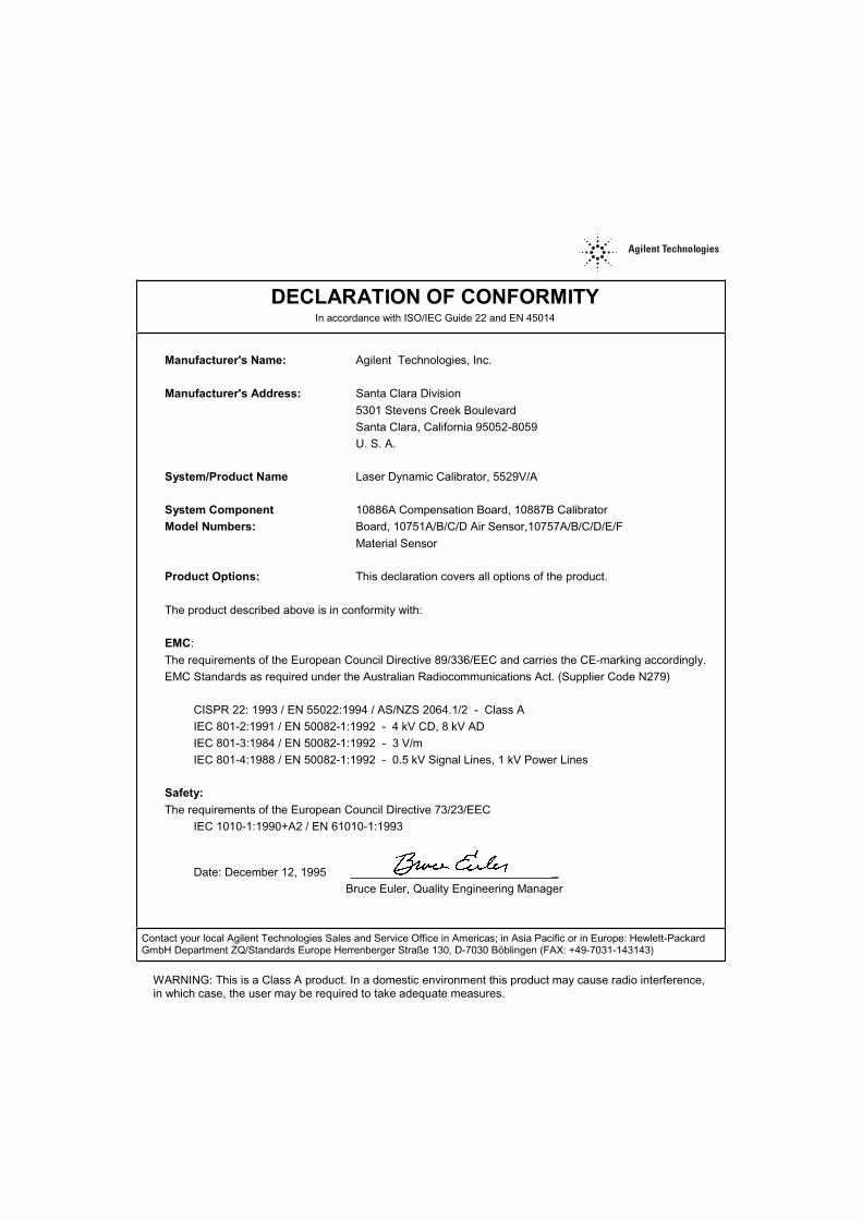
In accordance with ISO/IEC Guide 22 and EN 45014
Agilent Technologies, Inc.
Santa Clara Division
5301 Stevens Creek BoulevardSanta Clara, California 95052-8059U. S. A.
Laser Dynamic Calibrator, 5529V/A
10886A Compensation Board, 10887B CalibratorBoard, 10751A/B/C/D Air Sensor,10757A/B/C/D/E/F
Material Sensor
This declaration covers all options of the product.
The product described above is in conformity with:
:
The requirements of the European Council Directive 89/336/EEC and carries the CE-marking accordingly.EMC Standards as required under the Australian Radiocommunications Act. (Supplier Code N279)
CISPR 22: 1993 / EN 55022:1994 / AS/NZS 2064.1/2 - Class AIEC 801-2:1991 / EN 50082-1:1992 - 4 kV CD, 8 kV ADIEC 801-3:1984 / EN 50082-1:1992 - 3 V/mIEC 801-4:1988 / EN 50082-1:1992 - 0.5 kV Signal Lines, 1 kV Power Lines
The requirements of the European Council Directive 73/23/EECIEC 1010-1:1990+A2 / EN 61010-1:1993
Date: December 12, 1995 _
Bruce Euler, Quality Engineering Manager
Contact your local Agilent Technologies Sales and Service Office in Americas; in Asia Pacific or in Europe: Hewlett-PackardGmbH Department ZQ/Standards Europe Herrenberger Straße 130, D-7030 Böblingen (FAX: +49-7031-143143)
WARNING: This is a Class A product. In a domestic environment this product may cause radio interference,in which case, the user may be required to take adequate measures.

Continued from front matter. . .
7.NC.NL.A.03.11.97.R1.J.CW4B
Warranty (contd)Agilent does not warrant that the operation of Agilent products will be uninterrupted or error free. If Agilent is unable, within a reasonable time, to repair or replace any product to a condition as warranted, customer will be entitled to a refund of the purchase price upon prompt return of the product.
Agilent products may contain remanufactured parts equivalent to new in performance or may have been subjected to incidental use.
The warranty period begins on the date of delivery or on the date of installation if installed by Agilent. If customer schedules or delays Agilent installation more than 30 days after delivery, warranty begins on the 31st day from delivery.
Warranty does not apply to defects resulting from (a) improper or inadequate maintenance or calibration, (b) software, interfacing, parts or supplies not supplied by Agilent, (c) unauthorized modification or misuse, (d) operation outside of the published environmental specifications for the product, or (e) improper site preparation or maintenance.
TO THE EXTENT ALLOWED BY LOCAL LAW, THE ABOVE WARRANTIES ARE EXCLUSIVE AND NO OTHER WARRANTY OR CONDITION, WHETHER WRITTEN OR ORAL, IS EXPRESSED OR IMPLIED AND AGILENT SPECIFICALLY DISCLAIMS ANY IMPLIED WARRANTIES OR CONDITIONS OF MERCHANTABILITY,SATISFACTORY QUALITY, AND FITNESS FOR A PARTICULAR PURPOSE.
Agilent will be liable for damage to tangible property per incident up to the greater of $300,000 or the actual amount paid for the product that is the subject of the claim, and for damages for bodily injury or death, to the
extent that all such damages are determined by a court of competent jurisdiction to have been directly caused by a defective Agilent product.
TO THE EXTENT ALLOWED BY LOCAL LAW, THE REMEDIES IN THIS WARRANTY STATEMENT ARE CUSTOMER’S SOLE AND EXCLUSIVE REMEDIES. EXCEPT AS INDICATED ABOVE, IN NO EVENT WILL AGILENT OR ITS SUPPLIERS BE LIABLE FOR LOSS OF DATA OR FOR DIRECT, SPECIAL, INCIDENTAL, CONSEQUENTIAL (INCLUDING LOST PROFIT OR DATA), OR OTHER DAMAGE, WHETHER BASED IN CONTRACT, TORT, OR OTHERWISE.
For consumer transactions in Australia and New Zealand: the warranty terms contained in this statement, except to the extent lawfully permitted, do not exclude, restrict or modify and are in addition to the mandatory statutory rights applicable to the sale of this product to you.AssistanceProduct maintenance agreements and other customer assistance agreements are available for Agilent products.
For any assistance, contact your nearest Agilent Sales and Service Office.
Safety Considerations (contd)
WARNINGINSTRUCTIONS FOR ADJUSTMENTS WHILE COVERS ARE REMOVED AND FOR SERVICING ARE FOR USE BY SERVICE-TRAINED PERSONNEL ONLY. TO AVOID DANGEROUS ELECTRIC SHOCK, DO NOT PERFORM SUCH ADJUSTMENTS OR SERVICING UNLESS QUALIFIED TO DO SO.
Acoustic Noise EmissionsLpA<47 dB at operator position, at normal operation, tested per EN 27779. All data are the results from type test.
GeräuschemissionLpA<47 dB am Arbeits platz, normaler Betrieb, geprüft nach EN 27779. Die Angagen beruhen auf Ergebnissen von Typenprüfungen.


*10747-90077*Manual Part Number 10747-90077 Printed in U.S.A, OCTOBER 16, 2008


