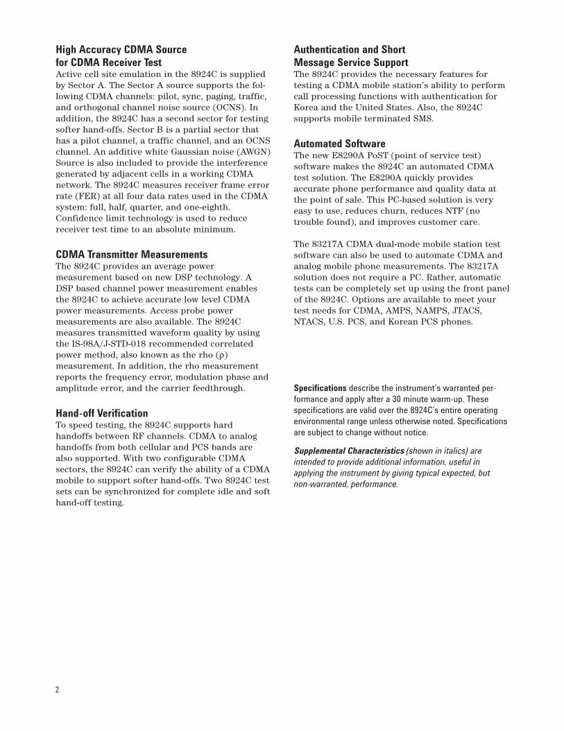
83236B PCS Interface 83217A CDMA Dual-Mode Mobile Station Test Software E8290A Point of Service Test (PoST) Software 30 MHz to 1000 MHz, 1700 MHz to 2000 MHz The Agilent Technologies 8924C CDMA mobile station test set provides the key set of measure- ments to verify the performance of dual-mode CDMA mobile phones operating from 500 to 1000 MHz. With the Agilent Technologies 83236B PCS Interface, the 8924C additionally offers CDMA mobile testing from 1700 to 2000 MHz. Acting as a calibrated, high performance CDMA base station, the 8924C verifies not only the parametric charac- teristics of CDMA phones, but also the functional aspects of phone performance. The 8924C’s full AMPS, NAMPS, EAMPS, TACS, NTACS, ETACS, and JTACS test capability saves you space, cost, and training expenses by allowing you to make both analog and CDMA digital measurements with the same instrument. For complete call processing verification, the 8924C supports both mobile and base station initiated call connect and disconnect. Once a phone call is established, verifying the overall functionality of a CDMA mobile is simple using the 8924C’s voice echo mode. For testing a variety of protocol formats, the 8924C offers six user selectable protocol stacks: IS-95, IS-95A, TSB-74, J-STD-008, ARIB T53, and KOREAN PCS. The 8924C also supports a number of service options, including 9600 BPS and 14,400 BPS traffic channel configurations. Agilent 8924C CDMA Mobile Station Test Set Data Sheet
Transcript
83236B PCS Interface 83217A CDMA Dual-Mode Mobile Station Test SoftwareE8290A Point of Service Test (PoST) Software
30 MHz to 1000 MHz, 1700 MHz to 2000 MHz
The Agilent Technologies 8924C CDMA mobile station test set provides the key set of measure-ments to verify the performance of dual-modeCDMA mobile phones operating from 500 to 1000
MHz. With the Agilent Technologies 83236B PCSInterface, the 8924C additionally offers CDMAmobile testing from 1700 to 2000 MHz. Acting as acalibrated, high performance CDMA base station,the 8924C verifies not only the parametric charac-teristics of CDMA phones, but also the functionalaspects of phone performance.
The 8924C’s full AMPS, NAMPS, EAMPS, TACS,NTACS, ETACS, and JTACS test capability savesyou space, cost, and training expenses by allowingyou to make both analog and CDMA digital measurements with the same instrument.
For complete call processing verification, the8924C supports both mobile and base station initiated call connect and disconnect. Once aphone call is established, verifying the overall functionality of a CDMA mobile is simple using the8924C’s voice echo mode. For testing a variety ofprotocol formats, the 8924C offers six user selectable protocol stacks: IS-95, IS-95A, TSB-74, J-STD-008, ARIB T53, and KOREAN PCS. The8924C also supports a number of service options,including 9600 BPS and 14,400 BPS traffic channelconfigurations.
Agilent 8924CCDMA Mobile Station Test SetData Sheet
2
High Accuracy CDMA Source for CDMA Receiver TestActive cell site emulation in the 8924C is suppliedby Sector A. The Sector A source supports the fol-lowing CDMA channels: pilot, sync, paging, traffic,and orthogonal channel noise source (OCNS). Inaddition, the 8924C has a second sector for testingsofter hand-offs. Sector B is a partial sector thathas a pilot channel, a traffic channel, and an OCNSchannel. An additive white Gaussian noise (AWGN)Source is also included to provide the interferencegenerated by adjacent cells in a working CDMAnetwork. The 8924C measures receiver frame errorrate (FER) at all four data rates used in the CDMAsystem: full, half, quarter, and one-eighth.Confidence limit technology is used to reducereceiver test time to an absolute minimum.
CDMA Transmitter MeasurementsThe 8924C provides an average power measurement based on new DSP technology. ADSP based channel power measurement enablesthe 8924C to achieve accurate low level CDMApower measurements. Access probe power measurements are also available. The 8924C measures transmitted waveform quality by usingthe IS-98A/J-STD-018 recommended correlatedpower method, also known as the rho (ρ) measurement. In addition, the rho measurementreports the frequency error, modulation phase andamplitude error, and the carrier feedthrough.
Hand-off VerificationTo speed testing, the 8924C supports hard handoffs between RF channels. CDMA to analoghandoffs from both cellular and PCS bands arealso supported. With two configurable CDMA sectors, the 8924C can verify the ability of a CDMAmobile to support softer hand-offs. Two 8924C testsets can be synchronized for complete idle and softhand-off testing.
Authentication and Short Message Service SupportThe 8924C provides the necessary features for testing a CDMA mobile station’s ability to performcall processing functions with authentication forKorea and the United States. Also, the 8924C supports mobile terminated SMS.
Automated SoftwareThe new E8290A PoST (point of service test) software makes the 8924C an automated CDMAtest solution. The E8290A quickly provides accurate phone performance and quality data atthe point of sale. This PC-based solution is veryeasy to use, reduces churn, reduces NTF (no trouble found), and improves customer care.
The 83217A CDMA dual-mode mobile station testsoftware can also be used to automate CDMA andanalog mobile phone measurements. The 83217Asolution does not require a PC. Rather, automatictests can be completely set up using the front panelof the 8924C. Options are available to meet yourtest needs for CDMA, AMPS, NAMPS, JTACS,NTACS, U.S. PCS, and Korean PCS phones.
Specifications describe the instrument’s warranted per-formance and apply after a 30 minute warm-up. Thesespecifications are valid over the 8924C’s entire operatingenvironmental range unless otherwise noted. Specificationsare subject to change without notice.
Supplemental Characteristics (shown in italics) are intended to provide additional information, useful in applying the instrument by giving typical expected, but non-warranted, performance.
3
8924C ANALOG MODE SPECIFICATIONSCall Processing FunctionalityStandards: AMPS, NAMPS, TACS, JTACS, and NTACS
Registration Support: Zone Registration
Call Control: BS call originate and disconnect, MS call originate and disconnect
Authentication: Registration, paging, origination,SSD update, and unique challenge
Orders: Power levels 0 through 7, maintenance, and alert
Hand-off Support: Hand-off to new frequency, between narrow channel and wide channel
Signal GeneratorRF FrequencyRange:
Standard: 30 MHz to 1000 MHzWith the 83236B:800 MHz to 960 MHz1710 MHz to 1785 MHz1805 MHz to 1910 MHz1930 MHz to 1990 MHzUsable from 1700 to 1999.999999 MHz
Accuracy and Stability: Same as reference oscillator±0.015 Hz
Switching Speed: <150 ms to be within 100 Hz ofcarrier frequency
Resolution: 1 Hz
OutputRF In/Out ConnectorLevel Range:
Standard: -127 dBm to -10.5 dBm into 50 ΩWith the 83236B: -130 dBm to -20 dBm into 50 Ω
Level Accuracy:Standard: ±1.2 dB (Level ≥-127 dBm)Typically ±1.0 dB for all levelsWith the 83236B:±1.8 dB, at 25° C ±10° C±2.0 dB, at 0° C to 55° C±1.0 dB typically
Reverse Power:Standard: 3 WWith the 83236B: 10 W
SWR:Standard: <1.5:1With the 83236B: <1.2:1
Duplex Out/RF Out Only ConnectorLevel Range:
Standard: -127 dBm to +3.5 dBm into 50 ΩWith the 83236B: -130 dBm to -10 dBm into 50 Ω
Level Accuracy:Standard: ±1.0 dBWith the 83236B:±1.8 dB, at 25 °C ±10 °C±2.0 dB, at 0 °C to 55 °C±1.0 dB typically
Reverse Power: 200 mW maximum
SWR: Standard: <2.0:1 (level <-7.5 dBm)With the 83236B: <1.6:1
Resolution: 0.1 dB (setable in 0.01 dB increments)
Spectral PurityAll specifications are for ≤-2.5 dBm output level at Duplex Out or ≤-16.5 dBm output level at RFIn/Out
Residual FM (CCITT, rms):Standard:<7 Hz for 500 MHz <fc≤1000 MHz<4 Hz for 250 MHz ≤fc ≤500 MHz<7 Hz for 30 MHz ≤fc <250 MHzWith the 83236B:<7 Hz for 810 MHz ≤fc ≤960 MHz<10 Hz for 1710 MHz ≤fc ≤1990 MHz
SSB Phase Noise:Standard: <-116 dBc/Hz (for >20 kHz offsets at a 1000 MHz carrier frequency)With the 83236B: <-100 dBc/Hz at >20 kHz offsets
FMMaximum FM Deviation (rates >25 Hz):
Standard:100 kHz; 30 to <249 MHz50 kHz; 249 to <501 MHz100 kHz; 501 to 1000 MHzWith the 83236B:100 kHz; 800 MHz to 960 MHz, 1710 MHz to 1785 MHz, 1805 MHz to 1910 MHz, 1930 MHz to 1990 MHz
FM Rate (1 kHz reference):Internal: DC to 25 kHz (1 dB BW)External:AC Coupled: 20 Hz to 75 kHz (typical -3 dB BW)DC Coupled: DC to 75 kHz (typical -3 dB BW)
FM Accuracy (1 kHz rate):≤10 kHz deviation: ±3.5% of setting ±50 Hz>10 kHz deviation ±3.5% of setting ±500 Hz
4
FM Distortion (THD+Noise, 0.3 to 3 kHz BW):<0.5 % at >4 kHz deviation and 1 kHz rate
Center Frequency Accuracy in DC FM Mode (externalsource impedance <1 kΩ): ±500 Hz (after DCFMzero), typically ±50 Hz
RF AnalyzerRF Frequency MeasurementMeasurement Range:
Standard: 30 MHz to 1000 MHzWith the 83236B:800 MHz to 960 MHz1710 MHz to 1785 MHz1805 MHz to 1910 MHz1930 MHz to 1990 MHzUsable from 1700 to 1999.999999 MHz
Level Range:Standard:RF In/Out: -10 dBm to +35 dBm (0.1 mW to 3 W)ANT In: -36 dBm to +20 dBmWith the 83236B:RF In/Out: -10 dBm to +40 dBm (0.1 mW to 10 W)
Accuracy: ±1 Hz plus timebase accuracy
Minimum Resolution: 1 Hz
RF Power MeasurementNote: To achieve the specified accuracy when measuring power at the RF In/Out port, the internal signal generator level must be 40 dB below the measured power or less than -20 dBm at theDuplex output port.
Frequency Range:Standard: 30 MHz to 1000 MHzWith the 83236B:800 MHz to 960 MHz1710 MHz to 1785 MHz1805 MHz to 1910 MHz1930 MHz to 1990 MHz
Input Connector: RF In/Out connector only
Measurement Range:Standard: -10 dBm to +35 dBm (0.1 mW to 3 W)With the 83236B: -13 dBm to +40 dBm (50 µW to 10 W)
Accuracy (after power meter zero):Standard:±5% of reading ±1 µW from 15° C to 35° C±10% of reading ±1 µW from 0° C to 55° CWith the 83236B:±5% of reading ±2.5 µW at 23° C ±10° C±10% of reading ±2.5 µW
SWR:Standard: <1.5:1With the 83236B: <1.2:1
Resolution:Standard:Power <10W: 1 mWPower <100 mW: 0.1 mWPower <10 mW: 0.01 mWWith the 83236B: 0.01 dB or 10 µW
FM MeasurementFrequency Range:
Standard: 30 MHz to 1000 MHzWith the 83236B:800 MHz to 960 MHz1710 MHz to 1785 MHz1805 MHz to 1910 MHz1930 MHz to 1990 MHz
Deviation Range: 20 Hz to 75 kHz
Sensitivity: 2 µV (15 kHz IF BW, High SensitivityMode, 0.3 to 3 kHz BW),1 Typically <1 µV (12 dBSINAD, fc ≥30 MHz)
1. Possible degradation in the 1700 to 1999 MHz bandwidth.
5
Accuracy (20 Hz to 25 kHz rates, deviation ≤25 kHz): ±4 %of reading plus residual FM and noise contribution
Bandwidth (3 dB): 2 Hz to 70 kHz (DCFM measurements also available)
THD+Noise: <1% for ≥5 kHz Deviation and 1 kHzrate in a 0.3 to 3 kHz BW1
Input Level Range for Specified Accuracy:Standard:-28 to +35 dBm at RF In/Out (1.6 µW to 3 W)-50 to +14 dBm at Ant InWith the 83236B: -36 dBm to +40 dBm
Residual FM and Noise (0.3 to 3 kHz, rms):Standard: <7 HzWith the 83236B: <10 Hz
Absolute MeasurementsLevel: Results of absolute power in watts or dBmare determined by adding the ACP ratio from theSpectrum Analyzer to the carrier power measurement obtained from the input section RF power detector.
Level Range:RF In/Out: -10 dBm to +35 dBmAntenna In: Not available
Channel Standards: MS AMPS, US PCS, Korean PCS 0, Korean PCS 1, Japan CDMA, MS NAMPSUpper/Middle/ Lower, MS TACS, MS ETACS, MSNTACS, MS JTACS, and User Defined (PCS bandsrequire the 83236B PCS Interface).
Base Station Parameters: NID, SID, BASE_ID, CountryCode, Network Code, SRCH_WIN_A, SRCH_WIN_N,SRCH_WIN_R, CDG Esc Mode on/off, Register SID,Register NID, and Power-On Registration on/off.
Access Probe Parameters: NOM_PWR,NOM_PWR_EXT, INIT_PWR, PWR_STEP, PAM_SZ,NUM_STEP, MAX_REQ_SEQ, and MAX_RSP_SEQ.
Paging Channel Parameters: Paging Data Rate (full orhalf rate), NUM_PAGES.
Hand-off Support:CDMA to CDMA Hard (RF Frequency)CDMA Softer (between two sectors)CDMA Soft (requires two units)CDMA to Analog (intra band)CDMA PCS to Analog cellular
CDMA to Analog Hand-off: Execute, System Type,Channel, SAT, and Power Level.
Authentication: Registration, paging, origination,SSD update, data burst, and unique challenge.
Short Message Service: Mobile terminated on pagingor traffic channel
Call Status Indicators: Transmitting (cell active),Registering, Page Sent, Access Probe Received,Connected, Softer Hand-off, Hard Hand-off, ServiceOption 002/009.
SMS In Progress, MS Acknowledge Received. Allindicators are also available over GPIB.
Speech Encoding: None (No vocoder)
Speech Echo Mode: Three user selectable fixeddelays: 0 seconds, 2 seconds, and 5 seconds.
CDMA Data Source:Pseudorandom data (CCITT 215–1 pattern)Voice Echo1 kHz Tone400 Hz ToneAudio Chirp (3 second sweep from 5 Hz to 3.75 kHz)
Closed Loop Power Control:Supports True Closed Loop Power ControlOpen Loop (Alternating 0 and 1 power control bits)Always UpAlways DownOff (no puncturing, requires special mode inmobile)
Closed Loop Change Modes:Step n Up (up to 150 bits)Step n Down (up to 150 bits)Ramp of n Up followed by n Down power (max. 150)
Open Loop Power Control: Supported through varyingthe level of CDMA Generator. CDMA analyzer auto-ranges to the ideal RF power level for the nominallyexpected open loop response.
8
Ideal Mobile Power Display: Reports the ideal openloop power for the mobile’s transmitter based uponthe forward link power set on the 8924C, the current protocol mode, and the set values ofNOM_PWR, NOM_PWR_EXT (J-STD-008 modeonly), and INIT_PWR.
Mobile Station FER Reporting: User selectable numberof frames (from predefined list). Report by numberof frames or by user defined number of errors.
Adjacent Cell Mobile Reporting: Displays status, PNoffset, strength, and keep bit for all pilots found bythe CDMA mobile and reported via pilot strengthmessages. Also displays the current user set PNoffsets and strengths of Sector A and Sector B toaid in verifying mobile performance.
Neighbor List Support: Automatically generates a listof seven neighbors based on the user entry ofSector A PN offset, Sector B PN offset, and PilotIncrement.
Mobile Station Identification: 10-digit phone number(IS-95 mode only), MIN (IS-95 mode only with hexentry), IMSI (MCC + MNC + MSIN), or AUTO (usespower-on or user initiated registration to obtainthe mobile ID).
Registration: Supports mobile power-on registration,timer-based registration (registration period parameter settable from 29 to 85, 12.18 to 199515seconds), implicit, or user-initiated registration(modulates SID to force the mobile to perform azone based registration) via GPIB command orfront panel button.
IMSI Support: Class 0 only in TSB-74 and J-STD-008protocols:
IMSI Mode: Class 0, Type 3 only
Auto Mode: The phone’s registration subclass is used by the instrument to page the phone.
Mobile Database: Upon registration, the databasecontains the following information:
IS-95 Mode: ESN, MIN1, MIN2, Phone Number, Dual-Mode, Slot Class, Slot Index, Protocol Revision, Power Class, Transmit Mode, and Called Number.
IS-95A, TSB74 and ARIB T-53 Modes: ESN, MCC, MNC, MSIN, Dual-mode, Slot Class, Slot Index, Protocol Revision, Power Class, Transmit Mode, and Called Number.
J-STD-008 and Korean PCS Modes: ESN, MCC,MNC, MSIN, Slot Class, Slot Index, ProtocolRevision, Band Class, EIRP Class, Operation Modes, and Called Number.
Retrievable Mobile Parameters:
IS-95/IS-95A Modes: MUX1_REV_(1 to 8, 11 to 14),MUX1_FOR_(1 to 14), PAG_(1 to 7), ACC_(1 to 8), and LAYER2_RTC(1 to 5).
TSB-74/J-STD-008 Modes: In addition to the aboveparameters, these parameters are available: MUX2_REV_(1 to 25), and MUX2_FOR_(1 to 26).
Protocol Logging: Two rear panel serial ports allowlogging of paging/access channel messages and forward/reverse traffic channel messages. Requiresan external PC running terminal emulation soft-ware connected to the rear panel serial ports.
CDMA Signal GeneratorCDMA ChannelsAdditive White Gaussian Noise
Sector A with Selectable PN Offset:Pilot Channel at Walsh Code 0Sync Channel at Walsh Code 32Paging Channel at Walsh Code 1Traffic Channel with selectable Walsh CodeOCNS Channel with selectable Walsh Code
Sector B with Selectable PN Offset:Pilot Channel at Walsh Code 0Traffic Channel with Selectable Walsh CodeOCNS Channel with Selectable Walsh Code
FrequencyFrequency Range:
Standard: 501 MHz to 1000 MHzUsable from 30 MHz to 248.9 MHzWith the 83236B:800 MHz to 960 MHz1710 MHz to 1785 MHz1805 MHz to 1910 MHz1930 MHz to 1990 MHzUsable from 1700 to 1999.999999 MHz
Frequency Resolution: 1 Hz
Frequency Accuracy: Same as reference oscillator accuracy ±0.015 Hz
AmplitudeComposite Signal Output Level Range:
Standard:RF In/Out: -109 dBm/1.23 MHz to -21.5 dBm/1.23 MHzDuplex Out: -109 dBm/1.23 MHz to -7.5 dBm/1.23 MHzWith the 83236B:RF In/Out: -109 dBm/1.23 MHz to -20.01 dBm/1.23 MHz (-23 dBm/1.23 MHz max. if AWGN only)RF Out Only: -109 dBm/1.23 MHz to -10.01 dBm/1.23 MHz (-13 dBm/1.23 MHz max. if AWGNonly)
9
Composite Signal Output Level Accuracy: (Using the IS-98A sensitivity setup)Standard:
AWGN Off: ±1.5 dB±1.0 dB typicallyAWGN On: ±2.0 dB
With the 83236B:AWGN Off: ±2.1 dB, at 25 °C ±10 °C±2.3 dB. at 0 °C to 55 °C±1.3 dB typicallyAWGN On:±2.6 dB. at 25 °C ±10 °C±2.8 dB. at 0 °C to 55 °C
Attenuator Hold:Standard: -15 dB from attenuator setting whenhold is enabled.
With the 83236B: Up to -60 dB from attenuator setting when hold is enabled depending upon the initial setting level. Holds mechanical attenuator in the 83236B and uses the electronic attenuator in the 8924C to provide low-transient amplitude transitions.
Composite Signal Output Power: Equal to the sum ofthe individually settable power levels for AWGN,Sector A, and Sector B.
Maximum Individual Signal Dynamic Range: The maxi-mum dynamic range of any CDMA channel (AWGN,Sector A: Pilot, Sync, Paging, Traffic, or OCNS,Sector B: Pilot, Traffic, or OCNS) is from 0 dB to -30 dB relative to the total composite output power.Paging and Traffic channels may have more or lessdynamic range depending on the data rate in use.
AWGN Bandwidth: Typically >1.8 MHz bandwidth. Because the reported total composite power andAWGN power is in terms of dBm in a 1.23 MHzbandwidth, the actual broadband output poweras seen by a power meter on the front panel willbe higher than reported on the front panel.
Sector A OCNS Channel Relative Level Range:Automatically calculated from other Sector A chan-nel relative levels to provide the set Sector A power.
Sector B OCNS Channel Relative Level Range:Automatically calculated from other Sector Bchannel relative levels to provide the set Sector Bpower.
Individual Channel Amplitude Resolution: 0.01 dB
Relative CDMA Channel Level Accuracy:AWGN to Traffic Channel: <0.2 dB, ±5 °C from the lasttemperature at which PCB_CAL was run for valuesof Eb/Nt from 1 dB to 10 dB.
Between any Two CDMA Channels: <0.2, dB ±5 °C fromthe last temperature at which PCB_CAL was run.
CDMA ModulationModulation Type: QPSK per TIA IS-95A/J-STD-008
Residual ρ: Better than 0.97, typically >0.98
Carrier Feedthrough: Better than -30 dBc, typicallybetter than -30 dBc
Adjacent Channel Spectral Purity: <-45 dBc at ±895kHz offset from carrier frequency relative to thetotal carrier power in a 1.23 MHz bandwidth.
Rate Set Support: Rate set 1 (9600 bps traffic -8 kbpsvoice)
Rate set 2 (14.4 kbps traffic -13 kbps voice)
Data Rate Transmission Modes: IS-95A/J-STD-008defined base station modes including full rate, halfrate, quarter rate, one-eighth rate data transmis-sion, and variable rate with equally weighted, randomly spaced occurrences of each rate.
Data Generator Patterns:Pseudorandom data (CCITT 215-1 pattern)1 kHz tone400 Hz tone
Audio Chirp (3 second sweep from 10 Hz to 3.75)
Tones and chirp conform to IS-96A (Service Option1), IS-127 (Service Option 3), and CDG-27 (ServiceOption 32768) vocoder standards
CDMA AnalyzerCDMA Average Power MeasurementNote: To achieve the specified accuracy when measuring power at the RF In/Out port of the8924C or the 83236B, the internal signal generatorlevel must be 40dB below the measured power orless than -20 dBm at the 8924C’s Duplex Outputport or the 83236B’s RF Out Only port.
Input Frequency Range: Standard: 30 MHz to 1000 MHzWith the 83236B:800 MHz to 960 MHz1710 MHz to 1785 MHz1805 MHz to 1910 MHz1930 MHz to 1990 MHz
Usable from 1700 to 1999.999999 MHz
Input Connector:Standard: RF In/Out connector on the 8924CWith the 83236B: RF In/Out connector on the 83236B
Measurement Bandwidth: Provides an accurate meas-ure of the total power for all present signals within±2 MHz of the specified operating frequency. Ifother signals are present outside of this frequencyrange, reduced measurement accuracy will result.
10
Maximum Input Level:Standard: +35 dBm (3 W continuous)With the 83236B: +37 dBm (5 W continuous)
Measurement Range:Standard: -10 dBm to +35 dBm.Usable to -20 dBm with degraded accuracyWith the 83236B: -13 dBm to +37 dBm
Measurement Method: Reports the overall averagepower for all active power control groups captured
Measurement Period: Measures over 1/2 of a CDMAframe (eight power control groups) in full, half,quarter, or one-eighth rate modes
Measurement Update Rate: Typically 1.5 readingsper second
Measurement Accuracy (after power meter zero): Standard:±5% ±1 µW at 25 °C ±10 °C±10% ±1 µW from 0 °C to +55 °CWith the 83236B:±5% ±2.5 µW at 23 °C ±10 °C±10% ±2.5 µW from 0 °C to +55 °C
CDMA Tuned Channel Power and Access Probe Power MeasurementsInput Frequency Range:
Standard: 30 MHz to 1000 MHzWith the 83236B:800 MHz to 960 MHz1710 MHz to 1785 MHz1805 MHz to 1910 MHz1930 MHz to 1990 MHzUsable from 1700 to 1999.999999 MHz
Input Connector: Standard: RF In/Out connector on the 8924CWith the 83236B: RF In/Out connector on the 83236B
Measurement Bandwidth: Measures the total powerin a 1.23 MHz bandwidth centered on the activereverse channel center frequency.
Maximum Input Level:Standard: +35 dBm (3 W continuous)With the 83236B: +37 dBm (5 W continuous)
Measurement Range:Standard: -50 dBm to +30 dBm, usable to -60 dBm
Measurement Update Rate: Typically two readingsper second
Measurement Accuracy: Relative Mode (Uncalibrated against average power):0 to -10 dB relative level: ±0.1 dB-10 to -20 dB relative level: ±0.2 dB-20 to -40 dB relative level: ±0.5 dB
Calibrated Mode (Calibrated against averagepower):
Standard: ±1.0 dB at ±10 °C from the calibration temperatureWith the 83236B Cellular bands (source level<-35 dBm/1.23 MHz): ±1.0 dB at ±10 °Cfrom the calibration temperatureWith the 83236B PCS bands (source level<-35 dBm/1.23 MHz): ±1.6 dB at ±10 °C from the calibration temperature
Temperature Drift: Typically 0.1 dB per 10 °C temperature change
Measurement Period: Measures power in a 1.23 MHzbandwidth over 1/2 of a CDMA frame (eight powercontrol groups) in full, half, quarter, or one-eighthrate modes.
Calibrate: Calibrates the channel power measure-ment over the entire operating frequency range ofthe currently selected RF Channel Standard. Thiscalibration requires the user to connect the DuplexOut Port to the RF In/Out port (or to connect theRF Out Only Port to the RF In/Out Port when usingthe 83236B) before initiating the calibration.
Alternate Channel Standard: Allows the selection of asecond channel standard to be calibrated when thechannel power calibration is performed. Alsoallows calibrating the entire cell band, PCS band,or all bands at one time. This allows switchingbetween to standards without having to recalibrateafter each RF Channel Standard change.
Uncalibrated Flag: Displays “Uncal” under theChannel Power measurement whenever the unitdetects that the channel power calibration has notbeen run for the currently set RF ChannelStandard.
Access Probe Power Measurement Triggering:Measurement automatically triggers above -55 dBm
CDMA Modulation MeasurementInput Frequency Range:
Standard: 30 MHz to 1000 MHzWith the 83236B:800 MHz to 960 MHz1710 MHz to 1785 MHz1805 MHz to 1910 MHz1930 MHz to 1990 MHzUsable from 1700 to 1999.999999 MHz
11
Modulation Measurement Format: OQPSK per TIA IS-95A/J-STD-008
ρ (rho) Measurement Input Level Range:Standard: -20 dBm to +35 dBmUsable to -25 dBm with degraded accuracyWith the 83236B: -25 dBm to +37 dBmUsable to -28 dBm with degraded accuracy
Range of ρ Measurement for Specified Accuracy:0.45 to 1.00
Measurement Update Rate: Typically 1.5 readingsper second
ρ Measurement Accuracy: ρ ±0.003
Frequency Error Measurement Range: ±1 kHz
Frequency Error Measurement Accuracy: ±30 Hz
Other Reported Parameters with ρ Measurement:Transmit time error (τ, time offset), frequencyerror, carrier feedthrough, amplitude error, andphase error
CDMA Frame Error Rate MeasurementFER Measurement Method: Data loopback per ServiceOption 002 or Service Option 009 supporting confidence limits as outlined in TIA/EIA-98-B.
Supported Data Rates for FER Measurement: Full, half,quarter, or one-eighth rate
Confidence Limit Range: User definable from 80.0% to99.9% and Off
Confidence Limit Statistical Model: Meets TIA/EIA-98-Bstatistical model parameters
FER Reported Parameters: Measured FER, number oferrors, number of frames tested, and one of the following: passed confidence limit, failed confi-dence limit, or max. frames (test indeterminate).
Conditions for Terminating FER Test (with confidence limits on):
Max Frames: Maximum number of frames to test completed, indicative of an indeterminate test result.Failed: Measured FER failed the specified FER limit with specified confidence.Passed: Measured FER passed the specified FER limit with specified confidence.
FER Measurement Indicators: Testing, passed, failed,and max. frames. All indicators are available overGPIB.
One Button Min/Max Power MeasurementMeasurement Method: Automatically sets the 8924Cto the nominal TIA/EIA-98-B test conditions forthe minimum power measurement and then maximum power measurement. Restores the 8924Cto the instrument state active before the measurement in initiated.
Measurement Output: Maximum TX power and minimum TX power measured
Measurement Rate: Approximately 7 seconds permeasurement
CDMA Reverse Channel Spectrum DisplayFrequency Range: Fixed to the active CDMA reversechannel setting. Not independently adjustable.
Frequency Span/Resolution Bandwidth (coupled, maximum span of 5 MHz):
Residual Responses: <-70 dBm (no input signal, 0 dBattenuation)
Image Rejection: >50 dB
Non-harmonic Spurious Responses: >70 dB (for input signals ≤-30 dBm)
Level Accuracy: ±2.5 dB
Log Scale Linearity: ±2 dB (for input levels ≤-30 dBmand/or 60 dB range)
Displayed Average Noise Level: <-114 dBm (≤50 kHz spans)
Other Features: Peak hold, marker with frequencyand level readout, marker to peak, marker tonext peak, trace comparison A-B.
CDMA TriggersOutput Trigger Signals: Open loop power trigger onAUX CONTROL connector (line toggles wheneverthe output level of the 8924C’s CDMA source ischanged)
12
8924C CDMA COMMON SPECIFICATIONSRemote ProgrammingGPIB: Agilent Technologies implementation of IEEEStandard 488.2
Remote Front Panel Lockout: Allows remote user todisable the front panel display to improve GPIBmeasurement speed.
RS-232: 3-wire RJ-11 connector used for serial datain and out (no hardware handshake capability; twoRS-232 ports available in standard mode, one RS- 232 port available with the 83236B).
Centronics Port: Industry standard parallel printerport for hardcopies of test results or screen dumps.
Timebase Subsystem(For proper operation, this reference must belocked to either the 8924C’s high stability 10 MHztimebase output on the rear panel or to an external, high quality reference.)
Frame Clock BNC Output (CDMA Mode Only): Userselectable output of one of the following clocks viathis BNC:
1.25 msec20 msec frame clock26.67 msec short sequence clock80 msec clockEvery even second (PP2S)
TTL Sub Min. D Connector: Individual pins for 1.25 msec, 20 msec frame clock, 26.67 msec shortsequence clock, 80 msec clock, and every even second (PP2S).
Ovenized ReferenceAging Rate: <0.005 ppm pk-pk/day, <±0.1 ppm peryear (±85 Hz at 850 MHz in one year)
Warm-up: ±0.1 ppm in 5 minutes, ±0.01 ppm in 15minutes
Temperature: <0.01 ppm
Supply Voltage: 2 x 10⁻⁹ (±1%)
Rear Panel BNC Connectors:Output Frequency: 10 MHzOutput Level: 0 dBm ±3 dB into 50 Ω
Store/RecallAvailable RAM: Approximately 928 Kbytes of useravailable RAM. When running the 83217A Dual-mode CDMA Mobile Station Test Software, about280 Kbytes of RAM is available for save/recall use.
Memory CardCard Compatibility: Single industry standard PCMCIA slot that accepts type I and type II SRAM and ROM cards.
Storage Capability: Allows for the storage andretrieval of IBASIC programs, IBASIC programparameter and results data, input of new calibra-tion data, and long-term storage of Store/Recallinformation.
Firmware Upgrades: Accepts PCMCIA memory cardsto allow automatic loading of new firmware for theHost CPU, Protocol CPU, DSP, and Channel CardCPU’s without opening the 8924C (order 8924 CRT Option R58 for latest version; contact AgilentTechnologies if unit contains firmware revisionA.02.37 or less).
13
General SpecificationsDimensions (HxWxD):
Standard: 177 H x 426 W x 629 D mm (7 x 16.75 x 24.75 inches)With the 83236B: 254 H x 426 W x 574 D mm(12 x 16.75 x 24.75 inches) using the optional bench-top cabinet
Power:8924C: 100 V to 240 V, 50/60 Hz, nominally 400 VA83236B: 90 V to 132 V, 198 V to 264 V, 47 to 63 Hz, 100 VA maximum
Calibration Interval: 24 months
EMI: Standard: Conducted and Radiated interferencemeets CISPR-11, IEC 801-2, IEC 801-3, and IEC801-4.With the 83236B: Conducted and Radiatedinterference meets IEC 801-3.
Leakage: At RF Generator output levels <-40 dBm,typical radiated leakage is <1 µV induced in aresonant dipole antenna 25 mm (one inch) awayfrom any surface except the rear panel. Spuriousleakage levels are typically <5 µV in a resonantdipole antenna 25 mm (1 inch) away from anysurface except the rear panel. Spurious leakagelevels at the rear panel are typically <5 µV in aresonant dipole antenna at a distance of 250 mm(ten inches).
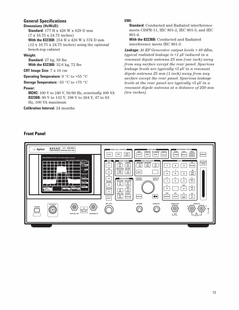
Front Panel
14
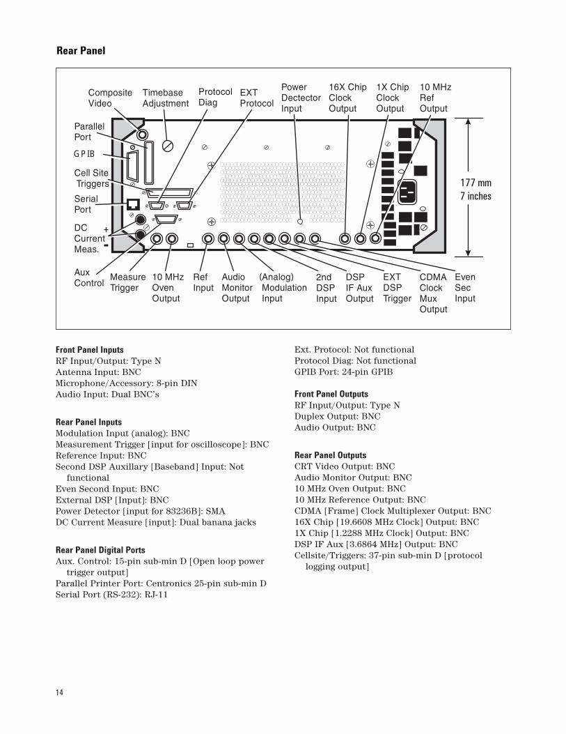
Front Panel InputsRF Input/Output: Type NAntenna Input: BNCMicrophone/Accessory: 8-pin DINAudio Input: Dual BNC’s
Rear Panel InputsModulation Input (analog): BNCMeasurement Trigger [input for oscilloscope]: BNCReference Input: BNCSecond DSP Auxillary [Baseband] Input: Not
functionalEven Second Input: BNCExternal DSP [Input]: BNCPower Detector [input for 83236B]: SMADC Current Measure [input]: Dual banana jacks
Rear Panel Digital PortsAux. Control: 15-pin sub-min D [Open loop power
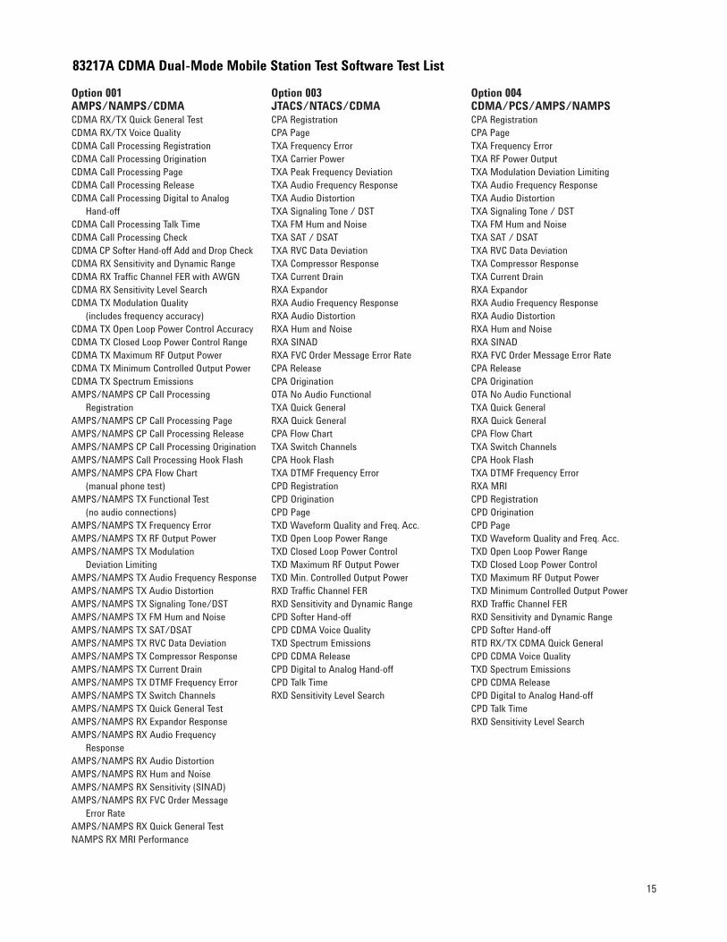
Option 001 AMPS/NAMPS/CDMACDMA RX/TX Quick General TestCDMA RX/TX Voice Quality CDMA Call Processing RegistrationCDMA Call Processing OriginationCDMA Call Processing PageCDMA Call Processing ReleaseCDMA Call Processing Digital to Analog
Hand-offCDMA Call Processing Talk TimeCDMA Call Processing CheckCDMA CP Softer Hand-off Add and Drop CheckCDMA RX Sensitivity and Dynamic RangeCDMA RX Traffic Channel FER with AWGNCDMA RX Sensitivity Level Search CDMA TX Modulation Quality
(includes frequency accuracy)CDMA TX Open Loop Power Control AccuracyCDMA TX Closed Loop Power Control RangeCDMA TX Maximum RF Output PowerCDMA TX Minimum Controlled Output PowerCDMA TX Spectrum EmissionsAMPS/NAMPS CP Call Processing
(no audio connections)AMPS/NAMPS TX Frequency ErrorAMPS/NAMPS TX RF Output PowerAMPS/NAMPS TX Modulation
Deviation LimitingAMPS/NAMPS TX Audio Frequency ResponseAMPS/NAMPS TX Audio DistortionAMPS/NAMPS TX Signaling Tone/DSTAMPS/NAMPS TX FM Hum and NoiseAMPS/NAMPS TX SAT/DSATAMPS/NAMPS TX RVC Data DeviationAMPS/NAMPS TX Compressor ResponseAMPS/NAMPS TX Current DrainAMPS/NAMPS TX DTMF Frequency ErrorAMPS/NAMPS TX Switch ChannelsAMPS/NAMPS TX Quick General TestAMPS/NAMPS RX Expandor ResponseAMPS/NAMPS RX Audio Frequency
ResponseAMPS/NAMPS RX Audio DistortionAMPS/NAMPS RX Hum and NoiseAMPS/NAMPS RX Sensitivity (SINAD)AMPS/NAMPS RX FVC Order Message
Error RateAMPS/NAMPS RX Quick General TestNAMPS RX MRI Performance
Option 003JTACS/NTACS/CDMACPA RegistrationCPA PageTXA Frequency ErrorTXA Carrier PowerTXA Peak Frequency DeviationTXA Audio Frequency ResponseTXA Audio DistortionTXA Signaling Tone / DSTTXA FM Hum and NoiseTXA SAT / DSATTXA RVC Data DeviationTXA Compressor ResponseTXA Current DrainRXA ExpandorRXA Audio Frequency ResponseRXA Audio DistortionRXA Hum and NoiseRXA SINADRXA FVC Order Message Error RateCPA Release CPA OriginationOTA No Audio FunctionalTXA Quick GeneralRXA Quick GeneralCPA Flow ChartTXA Switch ChannelsCPA Hook FlashTXA DTMF Frequency ErrorCPD RegistrationCPD OriginationCPD PageTXD Waveform Quality and Freq. Acc.TXD Open Loop Power RangeTXD Closed Loop Power ControlTXD Maximum RF Output PowerTXD Min. Controlled Output PowerRXD Traffic Channel FERRXD Sensitivity and Dynamic RangeCPD Softer Hand-offCPD CDMA Voice QualityTXD Spectrum EmissionsCPD CDMA ReleaseCPD Digital to Analog Hand-offCPD Talk TimeRXD Sensitivity Level Search
Option 004 CDMA/PCS/AMPS/NAMPSCPA RegistrationCPA PageTXA Frequency ErrorTXA RF Power OutputTXA Modulation Deviation LimitingTXA Audio Frequency ResponseTXA Audio DistortionTXA Signaling Tone / DST TXA FM Hum and NoiseTXA SAT / DSATTXA RVC Data DeviationTXA Compressor ResponseTXA Current DrainRXA ExpandorRXA Audio Frequency ResponseRXA Audio DistortionRXA Hum and NoiseRXA SINADRXA FVC Order Message Error RateCPA ReleaseCPA OriginationOTA No Audio FunctionalTXA Quick GeneralRXA Quick GeneralCPA Flow ChartTXA Switch ChannelsCPA Hook FlashTXA DTMF Frequency ErrorRXA MRICPD RegistrationCPD OriginationCPD PageTXD Waveform Quality and Freq. Acc.TXD Open Loop Power RangeTXD Closed Loop Power ControlTXD Maximum RF Output PowerTXD Minimum Controlled Output PowerRXD Traffic Channel FERRXD Sensitivity and Dynamic RangeCPD Softer Hand-offRTD RX/TX CDMA Quick GeneralCPD CDMA Voice QualityTXD Spectrum EmissionsCPD CDMA ReleaseCPD Digital to Analog Hand-offCPD Talk TimeRXD Sensitivity Level Search
83217A CDMA Dual-Mode Mobile Station Test Software Test List
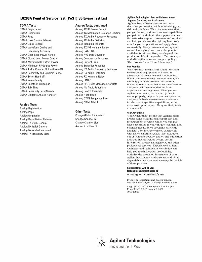
CDMA TestsCDMA RegistrationCDMA OriginationCDMA PageCDMA Base Station ReleaseCDMA Quick GeneralCDMA Waveform Quality and
Frequency AccuracyCDMA Open Loop Power RangeCDMA Closed Loop Power ControlCDMA Maximum RF Output PowerCDMA Minimum RF Output PowerCDMA Traffic Channel FER with AWGNCDMA Sensitivity and Dynamic RangeCDMA Softer Hand-offCDMA Voice QualityCDMA Spectrum EmissionsCDMA Talk TimeCDMA Sensitivity Level SearchCDMA Digital to Analog Hand-off
Analog TestsAnalog RegistrationAnalog PageAnalog Origination Analog Base Station ReleaseAnalog TX Quick GeneralAnalog RX Quick GeneralAnalog No Audio FunctionalAnalog TX Frequency Error
Analog Tests, continuedAnalog TX RF Power OutputAnalog TX Modulation Deviation LimitingAnalog TX Audio Frequency ResponseAnalog TX Audio DistortionAnalog Signaling Tone/DSTAnalog TX FM Hum and Noise Analog SAT/DSATAnalog RVC Data DeviationAnalog Compressor Response Analog Current Drain Analog Expandor Response Analog RX Audio Frequency ResponseAnalog RX Audio Distortion Analog RX Hum and Noise Analog SINADAnalog FVC Order Message Error RateAnalog No Audio FunctionalAnalog Switch ChannelsAnalog Hook FlashAnalog DTMF Frequency ErrorAnalog NAMPS MRI
Other TestsChange Global Parameters Change Channel ForChange Channel ListAccess to a User DLL
Agilent Technologies’ Test and MeasurementSupport, Services, and AssistanceAgilent Technologies aims to maximize the value you receive, while minimizing yourrisk and problems. We strive to ensure thatyou get the test and measurement capabilitiesyou paid for and obtain the support you need.Our extensive support resources and servicescan help you choose the right Agilent prod-ucts for your applications and apply themsuccessfully. Every instrument and systemwe sell has a global warranty. Support isavailable for at least five years beyond theproduction life of the product. Two conceptsunderlie Agilent’s overall support policy:“Our Promise” and “Your Advantage.”
Our Promise“Our Promise” means your Agilent test andmeasurement equipment will meet its advertised performance and functionality.When you are choosing new equipment, wewill help you with product information,including realistic performance specificationsand practical recommendations from experienced test engineers. When you useAgilent equipment, we can verify that itworks properly, help with product operation,and provide basic measurement assistancefor the use of specified capabilities, at noextra cost upon request. Many self-help toolsare available.
Your Advantage“Your Advantage” means that Agilent offers a wide range of additional expert test andmeasurement services, which you can pur-chase according to your unique technical andbusiness needs. Solve problems efficientlyand gain a competitive edge by contractingwith us for calibration, extra- cost upgrades,out-of-warranty repairs, and on-site educationand training, as well as design, system integration, project management, and otherprofessional services. Experienced Agilentengineers and technicians worldwide canhelp you maximize your productivity, optimize the return on investment of yourAgilent instruments and systems, and obtaindependable measurement accuracy for the lifeof those products.
Get assistance with all your test and measurement needs at: www.agilent.com/find/assist
Product specifications and descriptions in this document subject to change without notice.