138
Agilent Technologies Agilent B1505A Power Device Analyzer/ Curve Tracer Configuration and Connection Guide
Agilent B1505APower Device Analyzer/ Curve Tracer
Configuration and Connection Guide
Agilent Technologies

Notices© Agilent Technologies,2011, 2012
No part of this manual min any form or by any meelectronic storage and retion into a foreign languaagreement and written cAgilent Technologies, IncUnited States and intern
Inc. 2009, 2010,
ay be reproduced ans (including trieval or transla-ge) without prior onsent from . as governed by
ational copyright
Manual Part Number
B1505-90090
Edition
Edition 1, June 2009Edition 2, November 2009Edition 3, May 2010Edition 4, August 2010Edition 5, February 2011Edition 6, September 2012
Agilent Technologies, Inc.5301 Stevens Creek Blvd Santa Clara, CA 95051 USA
Warranty
The material contained in this docu-ment is provided “as is,” and is sub-ject to being changed, without notice, in future editions. Further, to the max-imum extent permitted by applicable law, Agilent disclaims all warran-ties, either express or implied, with regard to this manual and any infor-mation contained herein, including but not limited to the implied warran-ties of merchantability and fitness for a particular purpose. Agilent shall not be liable for errors or for incidental or consequential damages in connection with the furnishing, use, or perfor-mance of this document or of any information contained herein. Should Agilent and the user have a separate written agreement with warranty terms covering the material in this document that conflict with these terms, the warranty terms in the sep-arate agreement shall control.
Technology Licenses
The hardware and/or software described in this document are furnished under a license and may be used or copied only in accordance with the terms of such license.
Restricted Rights Legend
If software is for use in the performance of a U.S. Government prime contract or sub-
contract, Software is delivered and licensed as “Commercial computer soft-ware” as defined in DFAR 252.227-7014 (June 1995), or as a “commercial item” as defined in FAR 2.101(a) or as “Restricted computer software” as defined in FAR 52.227-19 (June 1987) or any equivalent agency regulation or contract clause. Use, duplication or disclosure of Software is subject to Agilent Technologies’ standard commercial license terms, and non-DOD Departments and Agencies of the U.S. Gov-ernment will receive no greater than Restricted Rights as defined in FAR 52.227-19(c)(1-2) (June 1987). U.S. Govern-ment users will receive no greater than Limited Rights as defined in FAR 52.227-14 (June 1987) or DFAR 252.227-7015 (b)(2) (November 1995), as applicable in any technical data.
laws.

In This DocumentThis document provides the following information about Agilent B1505A Power Device Analyzer/Curve Tracer.
• Chapter 1, “Configuration Guide.”
Describes how to configure the B1505A.
• Chapter 2, “N1259A Connection Guide.”
Describes how to connect the B1505A, the N1259A Test Fixture, and a device under test (DUT).
• Chapter 3, “N1265A Connection Guide.”
Describes how to connect the B1505A, the N1265A Test Fixture, and a device under test (DUT).
• Chapter 4, “Connection Guide for Wafer Prober and Your Own Test Fixture.”
Describes how to connect the B1505A, accessories, and a DUT interface such as wafer prober and your own test fixture.
• Chapter 5, “Accessory Dimensions.”
Describes dimensions and weight of accessories.


Contents
1. Configuration Guide2. N1259A Connection Guide
Input Connection . . . . . . . . . . . . . . . . . . . . . . . . . . . . . . . . . . . . . . . . . . . . . . . . . . . . . . 3-3To Connect Interlock Circuit . . . . . . . . . . . . . . . . . . . . . . . . . . . . . . . . . . . . . . . . . . . 3-4
Output Connection . . . . . . . . . . . . . . . . . . . . . . . . . . . . . . . . . . . . . . . . . . . . . . . . . . . . . 3-8To Connect DUT . . . . . . . . . . . . . . . . . . . . . . . . . . . . . . . . . . . . . . . . . . . . . . . . . . . . . 3-9To Use Options . . . . . . . . . . . . . . . . . . . . . . . . . . . . . . . . . . . . . . . . . . . . . . . . . . . . . 3-12N1259A-010 Inline Package Socket module. . . . . . . . . . . . . . . . . . . . . . . . . . . . . . 3-18N1259A-011 Universal Socket Module . . . . . . . . . . . . . . . . . . . . . . . . . . . . . . . . . . 3-19N1259A-012 Blank PTFE Board . . . . . . . . . . . . . . . . . . . . . . . . . . . . . . . . . . . . . . . . 3-20N1259A-013 Curve Tracer Test Adapter Socket Module . . . . . . . . . . . . . . . . . . . . 3-21
3. N1265A Connection Guide
Input Connection . . . . . . . . . . . . . . . . . . . . . . . . . . . . . . . . . . . . . . . . . . . . . . . . . . . . . . 4-4To Connect Interlock Circuit . . . . . . . . . . . . . . . . . . . . . . . . . . . . . . . . . . . . . . . . . . . 4-5
Output Connection . . . . . . . . . . . . . . . . . . . . . . . . . . . . . . . . . . . . . . . . . . . . . . . . . . . . . 4-9To Connect DUT . . . . . . . . . . . . . . . . . . . . . . . . . . . . . . . . . . . . . . . . . . . . . . . . . . . . 4-10Inline Package Socket module (N1265A-010) . . . . . . . . . . . . . . . . . . . . . . . . . . . . 4-17Universal Socket Module (N1265A-011). . . . . . . . . . . . . . . . . . . . . . . . . . . . . . . . . 4-18Curve Tracer Test Adapter Socket Module (N1265A-013) . . . . . . . . . . . . . . . . . . . 4-19Blank Silicon Plate (N1265A-002) . . . . . . . . . . . . . . . . . . . . . . . . . . . . . . . . . . . . . . 4-20Universal R-Box (N1265A-035) . . . . . . . . . . . . . . . . . . . . . . . . . . . . . . . . . . . . . . . . 4-21Protection Adapter (N1265A-040) . . . . . . . . . . . . . . . . . . . . . . . . . . . . . . . . . . . . . . 4-23Container (N1265A-045). . . . . . . . . . . . . . . . . . . . . . . . . . . . . . . . . . . . . . . . . . . . . . 4-23Prober System Cable (N1254A-524) . . . . . . . . . . . . . . . . . . . . . . . . . . . . . . . . . . . . 4-23
4. Connection Guide for Wafer Prober and Your Own Test Fixture
Connection Overview . . . . . . . . . . . . . . . . . . . . . . . . . . . . . . . . . . . . . . . . . . . . . . . . . . . 5-4
To Connect High Voltage R-Box . . . . . . . . . . . . . . . . . . . . . . . . . . . . . . . . . . . . . . . . . 5-13To Use Universal R-Box . . . . . . . . . . . . . . . . . . . . . . . . . . . . . . . . . . . . . . . . . . . . . . 5-14
To Connect HCSMU Adapter . . . . . . . . . . . . . . . . . . . . . . . . . . . . . . . . . . . . . . . . . . . . 5-16
To Connect Dual HCSMU Adapter. . . . . . . . . . . . . . . . . . . . . . . . . . . . . . . . . . . . . . . . 5-19To Connect 16493S-020 . . . . . . . . . . . . . . . . . . . . . . . . . . . . . . . . . . . . . . . . . . . . . . 5-19To Connect 16493S-021 . . . . . . . . . . . . . . . . . . . . . . . . . . . . . . . . . . . . . . . . . . . . . . 5-21
To Connect Protection Adapter . . . . . . . . . . . . . . . . . . . . . . . . . . . . . . . . . . . . . . . . . . 5-22
To Connect High Voltage Bias Tee . . . . . . . . . . . . . . . . . . . . . . . . . . . . . . . . . . . . . . . 5-24
To Connect Module Selector . . . . . . . . . . . . . . . . . . . . . . . . . . . . . . . . . . . . . . . . . . . . 5-26
Agilent B1505A Configuration and Connection Guide, Edition 6 Contents - 1

Contents
To Connect HVSMU/HCSMU Fast Switch . . . . . . . . . . . . . . . . . . . . . . . . . . . . . . . . . 5-31To Connect HVSMU Current Expander . . . . . . . . . . . . . . . . . . . . . . . . . . . . . . . . . . . . 5-33
To Connect Ultra High Current Expander . . . . . . . . . . . . . . . . . . . . . . . . . . . . . . . . . . 5-35Connecting System Cable to N1265A. . . . . . . . . . . . . . . . . . . . . . . . . . . . . . . . . . . 5-36
To Connect Ultra High Voltage Expander . . . . . . . . . . . . . . . . . . . . . . . . . . . . . . . . . . 5-37
To Install an Interlock Circuit . . . . . . . . . . . . . . . . . . . . . . . . . . . . . . . . . . . . . . . . . . . 5-39Procedure . . . . . . . . . . . . . . . . . . . . . . . . . . . . . . . . . . . . . . . . . . . . . . . . . . . . . . . . . 5-40To Connect Interlock Circuit . . . . . . . . . . . . . . . . . . . . . . . . . . . . . . . . . . . . . . . . . . 5-41
About Cable Connections . . . . . . . . . . . . . . . . . . . . . . . . . . . . . . . . . . . . . . . . . . . . . . 5-42To Make Connection to Reduce Leakage Current . . . . . . . . . . . . . . . . . . . . . . . . . 5-43To Make Connection to Measure Low Resistance . . . . . . . . . . . . . . . . . . . . . . . . 5-44To Connect UHVU/HVSMU/HVMCU Output . . . . . . . . . . . . . . . . . . . . . . . . . . . . . 5-45
5. Accessory Dimensions
Contents - 2 Agilent B1505A Configuration and Connection Guide, Edition 6

1 Configuration Guide
Information written in this chapter cannot cover the latest B1505A configuration.
This chapter will be updated soon.

Configuration Guide
Agilent B1505A Power Device Analyzer/Curve Tracer is a modular instrument which has ten slots for plug-in modules and four types of supported module. So you need to specify the module configuration and accessories you desire properly.
This chapter is the guide for configuring your B1505A, and consists of the following sections.
• “Furnished Accessories”
• “Modules and Mainframe Options”
• “Accessories for N1259A Test Fixture”
• “Accessories for Wafer Prober and Your Own Test Fixture”
• “Options and Accessories”
• “Retrofit Products for B1505A”
• “Upgrade Product from B1500A to B1505A”
• “Upgrade Kit for N1259AU Test Fixture”
• “Note for 4142B Users”
To make configuration of your B1505A
Follow the next steps. You can make the configuration of your B1505A as shown below.
Step Action
1 Make decision on the number of SMU modules to install. Two, three, or four?
2 Make decision on the type of module to install, high voltage, high current, high power, or all?
3 See “Modules and Mainframe Options” on page 1-6 and select the modules and the required options.
To confirm the furnished accessories, see “Furnished Accessories” on page 1-3.
4 For packaged device measurement:
Use the N1259A test fixture and the required accessories. See “Accessories for N1259A Test Fixture” on page 1-9 and select the required accessories.
If you use your own test fixture, see “Accessories for Wafer Prober and Your Own Test Fixture” on page 1-12 and select the accessories required and available for your measurement environment. Be careful about the connector type. The connector of accessories should be the same as or convertible to the connector of your own test fixture.
If you use a handler for production tests or others, consult a third party or a system integrator to make your measurement environment.
For on-wafer measurement:
Use a wafer prober. See “Accessories for Wafer Prober and Your Own Test Fixture” on page 1-12 and select the accessories required and available for the wafer prober. Be careful about the connector type. The connector of accessories should be the same as or convertible to the connector of the wafer prober. If you need, consult the wafer prober vendor.
1- 2 Agilent B1505A Configuration and Connection Guide, Edition 6

Configuration Guide
Furnished Accessories
Furnished AccessoriesThe B1505A is furnished with the accessories listed in the following tables. Table 1-1 lists the accessories for the B1505A mainframe. And Table 1-2 lists the measurement cables available for and furnished with the plug-in modules. Number of the furnished cables depends on the number of modules installed in the mainframe.
Table 1-1 Furnished Accessories
Description Qty. Description Qty.
16493J Interlock cable
1 16493L GNDU cable 1
16444A-001 USB keyboard
1 16444A-002 USB mouse
1
16444A-003 Stylus pen
1
Description Qty. Note
Manual CD 1 Stores electronic files of user manuals, literatures, and programming examples
Software CD 1 Desktop EasyEXPERT software CD-ROM
License sheet 1 License-to-use for Desktop EasyEXPERT Standard edition
Disk set 1 Disk set for Agilent 4155B/4155C/4156B/4156C firmware update
Label 1 Used to specify the SMU number. Only for the B1505A installed with SMU.
Power cable 1
Agilent B1505A Configuration and Connection Guide, Edition 6 1- 3

Configuration Guide
Furnished Accessories
Table 1-2 Measurement Cable Furnished with Modules
Description Quantity
16494A Triaxial cable, for HPSMU 2 ea./module
16493T HVSMU cable, for HVSMU 1 ea./module
16493S HCSMU cable, for HCSMU 1 ea./module
16493S-010 HCSMU Kelvin adapter, for HCSMU
Do not connect or put any conductor on the HCSMU Low Force and Low Sense terminals, outer conductor of the coaxial connectors. Connecting or putting conductor of circuit common, chassis ground, or any potential on causes the measurement error.
1 ea./module
N1300A CMU cable, for MFCMU 1 ea./module
1- 4 Agilent B1505A Configuration and Connection Guide, Edition 6
Configuration Guide
Furnished Accessories
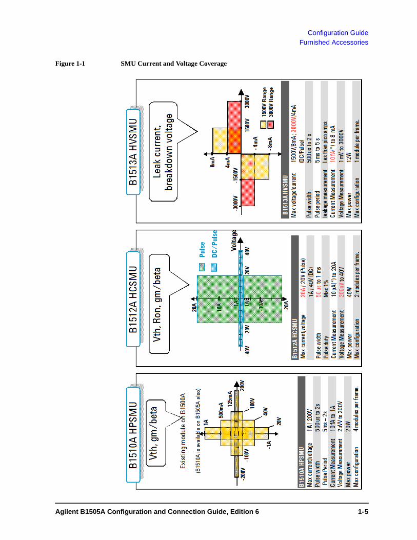
Figure 1-1 SMU Current and Voltage Coverage
4
Agilent B1505A Configuration and Connection Guide, Edition 6 1- 5

Configuration Guide
Modules and Mainframe Options
Modules and Mainframe OptionsThe B1505A can contain several combinations of modules; up to four dual-slot HPSMU modules, up to two dual-slot HCSMU modules, one dual-slot HVSMU, and one single-slot MFCMU.
• Select the modules to be installed in the B1505A mainframe
See Table 1-3 for the plug-in modules supported by the B1505A. See figures 1-1 and 1-2 for the key features of the modules.
• Specify cable length, 1.5 m or 3 m
See Table 1-4 for the options available for the B1505A.
• Select power line frequency, paper manual, rack mount kit, service options, and so on
See Table 1-4 for the options available for the B1505A.
Table 1-3 Plug-in Modules Supported by B1505A
NOTE Module Position
The installation order of the modules is: HPSMU, MFCMU, HCSMU, and HVSMU starting from the bottom of the mainframe.
Module type DescriptionSlots
occupied
Maximum number of modules installed
in B1505A 1
1. Total power consumption of all modules cannot exceed 84 W.
HPSMU 2
2. 4-HPSMU plus 1-HCSMU configuration and 3-HPSMU plus 2-HCSMU con-figuration are not supported.
High voltage source/monitor unit 2 4
HCSMU 2, 3
3. Dual HCSMU (DHCSMU) configuration is available if two HCSMU modules are installed in one mainframe and connected to the 16493S-020 Dual HCSMU Kelvin adapter or the 16493S-021 Dual HCSMU adapter. This configuration expands the maximum current up to ± 40 A (pulse), ± 2 A (DC).
High current source/monitor unit 2 2
HVSMU High power source/monitor unit 2 1
MFCMU Multi frequency capacitance measurement unit
1 1
GNDU 4
4. GNDU has been installed in the mainframe. You do not need to count for the number of slots occupied.
Ground unit - -
1- 6 Agilent B1505A Configuration and Connection Guide, Edition 6

Configuration Guide
Modules and Mainframe Options
Figure 1-2 High Voltage Capacitance Measurement (MFCMU + HVSMU)
•30
00V
DC b
iased
capa
citan
ce m
easu
reme
nt•
Spot
& S
weep
mea
sure
ment
•1 k
Hz -
5 M
Hz fr
eq. r
ange
•1p
F-10
nF w
ith 1
% ac
cura
cy (1
0 kH
z –1
MHz
) with
HV
Bias
•Le
ak m
easu
reme
nt w
hen
capa
citan
ce is
mea
sure
d. (u
A lev
Guar
dGu
ard
Forc
e Fo
rce
Coax
ial C
able
Man
ipul
ator
Man
ipul
ator
Bias
T
HVSM
U
S
Circ
uit c
omm
on
HV
Triax
. ca
ble
Hc Hp Lp Lc
CMU
R
C
Agilent B1505A Configuration and Connection Guide, Edition 6 1- 7

Configuration Guide
Modules and Mainframe Options
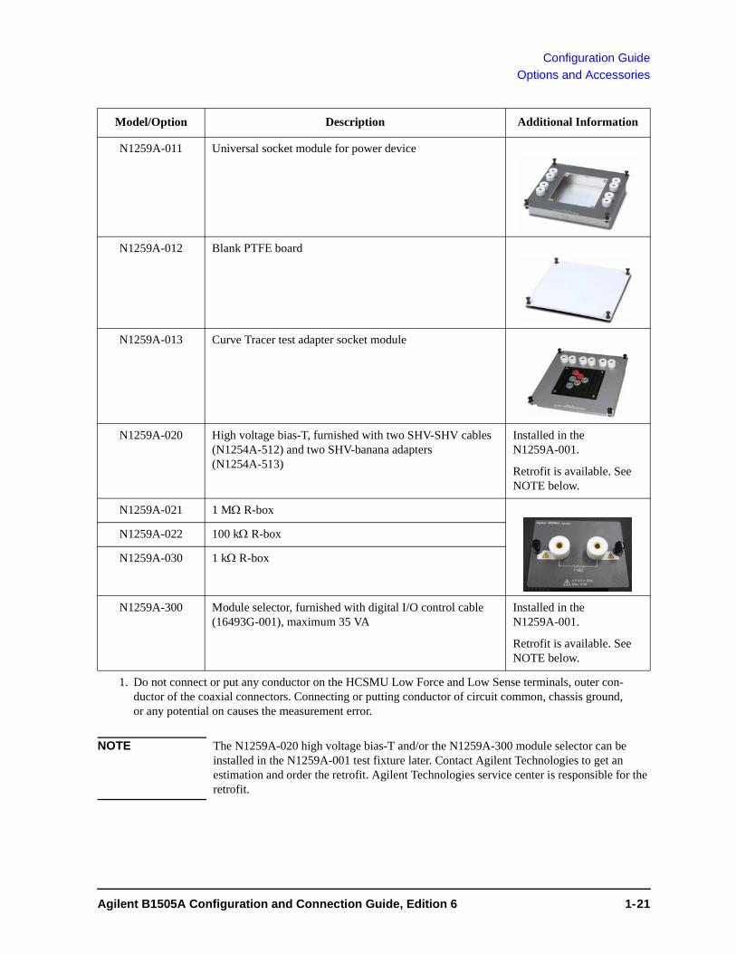
Table 1-4 Mainframe Options
DescriptionModel/ Option
Note
Mainframe
Power Device Analyzer/Curve Tracer B1505A See Table 1-1 on page 1-3 for furnished accessories.
Select modules (optional)
High Power Source/Monitor Unit module (HPSMU), 200V/1A
B1510A-FG Furnished with triaxial cable (16494A), 2 each. Four modules can be installed.
High Current Source/Monitor Unit module (HCSMU), 20A at 20V
B1512A-FG Furnished with HCSMU cable (16493S) and Kelvin adapter. Two modules can be installed.
High Voltage Source/Monitor Unit module (HVSMU), 3000V at 4mA
B1513A-FG Furnished with HVSMU cable (16493T). One module can be installed.
Multi Frequency Capacitance Measurement Unit module (MFCMU)
B1520A-FG Furnished with CMU cable (N1300A). One module can be installed.
Specify the cable length (mandatory)
1.5m cable 015 Same cable length for all furnished cables
3.0m cable 030
Specify the power line frequency (mandatory)
50Hz line frequency 050
60Hz line frequency 060
Select calibration options (optional)
ANSI Z540 compliant calibration A6J
Commercial calibration certificate with test data
UK6
Specify the language of the paper manuals if you need
Paper manual set, English ABA Printed manuals are optional. Order this option to get the paper manuals. Contains B1505A user guide, quick start guide, and self-paced training manual, EasyEXPERT user guide and self-paced training manual, and B1500 series programming guide.
Paper manual set, Japanese ABJ
Select rack mount kit (optional)
Rack mount kit 1CM
1- 8 Agilent B1505A Configuration and Connection Guide, Edition 6

Configuration Guide
Accessories for N1259A Test Fixture
Accessories for N1259A Test FixtureThe following table lists the accessories available for the N1259A test fixture. Select the required accessories. If you want to add options later, please refer to “Upgrade Kit for N1259AU Test Fixture” on page 1-25
Table 1-5 Accessories for N1259A Test Fixture
Description Model/Option Additional Information
Test Fixture, furnished with Kelvin socket module for inline package device (N1259A-010), four black connection wire (N1259A-509), six red connection wire (N1259A-508), built-in GNDUprotection adapter, and built-in HPSMUprotection adapter. Mandatory option.
N1259A-001
Kelvin socket module for inline package device (3pin)
N1259A-010
Universal socket module for power device N1259A-011
Agilent B1505A Configuration and Connection Guide, Edition 6 1- 9

Configuration Guide
Accessories for N1259A Test Fixture
Blank PTFE board N1259A-012
Curve tracer test adapter socket module N1259A-013
High voltage bias-T, furnished with two SHV-SHV cables (N1254A-512) and two SHV-banana adapters (N1254A-513)
N1259A-020 Installed in the N1259A-001.
Retrofit is available. See NOTE below.
1 M R-box N1259A-021
100 k R-box N1259A-022
1 k R-box N1259A-030
Module selector, furnished with digital I/O control cable (16493G-001), maximum 35 VA
N1259A-300 Installed in the N1259A-001.
Retrofit is available. See NOTE below.
Connection wire, red 1 ea. N1254A-508
Connection wire, black 1 ea. N1254A-509
Dolphin clip adapter, black 1 ea. and red 1ea. N1254A-510
Cable lag adapter, black 1 ea. and red 1ea. N1254A-511
Description Model/Option Additional Information
1- 10 Agilent B1505A Configuration and Connection Guide, Edition 6

Configuration Guide
Accessories for N1259A Test Fixture
NOTE The N1259A-020 high voltage bias-T and/or the N1259A-300 module selector can be installed in the N1259A-001 test fixture later. Contact Agilent Technologies to get an estimation and order the retrofit. Agilent Technologies service center is responsible for the retrofit.
SHV to SHV cable, 1 ea.
Two cables are furnished with the high voltage bias-T (N1259A-020).
The N1254A-513 adapter is required to connect the banana plug.
N1254A-512
SHV to banana adapter, 1 ea.
Two adapters are furnished with the high voltage bias-T (N1259A-020).
The N1254A-513 adapter is used with the N1254A-512 cable to connect the banana plug.
N1254A-513
Digital I/O control cable
The 16493G-001 cable is furnished with the module selector (N1259A-300).
16493G
Dual HCSMU combination adapter, for 40 A measurement
Output connectors are compatible with HCSMU.
This adapter is furnished with the dedicated cable, 30 cm for output connection.
Do not connect or put any conductor on the HCSMU Low Force and Low Sense terminals, outer conductor of the coaxial connectors. Connecting or putting conductor of circuit common, chassis ground, or any potential on causes the measurement error.
16493S-021
Description Model/Option Additional Information
Agilent B1505A Configuration and Connection Guide, Edition 6 1- 11
Configuration Guide
Accessories for Wafer Prober and Your Own Test Fixture
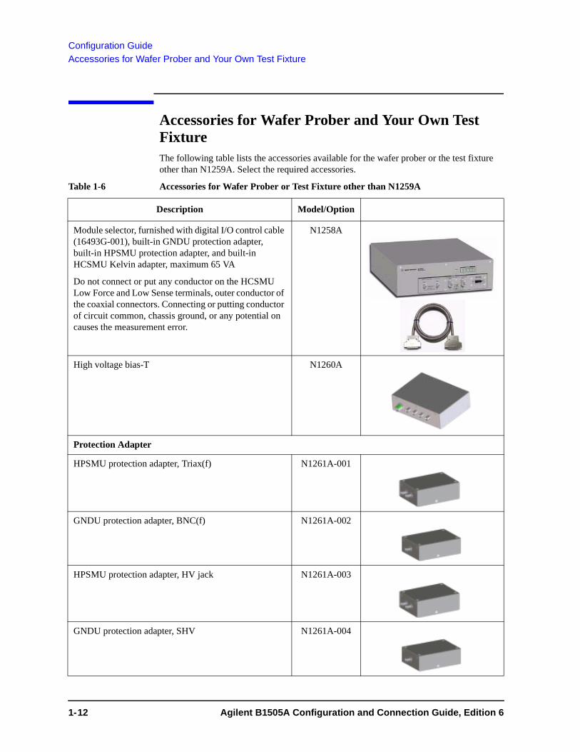
Accessories for Wafer Prober and Your Own Test FixtureThe following table lists the accessories available for the wafer prober or the test fixture other than N1259A. Select the required accessories.
Table 1-6 Accessories for Wafer Prober or Test Fixture other than N1259A
Description Model/Option
Module selector, furnished with digital I/O control cable (16493G-001), built-in GNDU protection adapter, built-in HPSMU protection adapter, and built-in HCSMU Kelvin adapter, maximum 65 VA
Do not connect or put any conductor on the HCSMU Low Force and Low Sense terminals, outer conductor of the coaxial connectors. Connecting or putting conductor of circuit common, chassis ground, or any potential on causes the measurement error.
N1258A
High voltage bias-T N1260A
Protection Adapter
HPSMU protection adapter, Triax(f) N1261A-001
GNDU protection adapter, BNC(f) N1261A-002
HPSMU protection adapter, HV jack N1261A-003
GNDU protection adapter, SHV N1261A-004
1- 12 Agilent B1505A Configuration and Connection Guide, Edition 6

Configuration Guide
Accessories for Wafer Prober and Your Own Test Fixture
High Voltage R-box
1 M R-box N1262A-001
100 k R-box N1262A-002
1 k R-box, Triax(f) N1262A-010
1 k R-box, SHV N1262A-011
HCSMU Adapter
HCSMU Kelvin adapter
Do not connect or put any conductor on the HCSMU Low Force and Low Sense terminals, outer conductor of the coaxial connectors. Connecting or putting conductor of circuit common, chassis ground, or any potential on causes the measurement error.
16493S-010
HCSMU non-Kelvin adapter
Do not connect or put any conductor on the HCSMU Low Force and Low Sense terminals, outer conductor of the coaxial connectors. Connecting or putting conductor of circuit common, chassis ground, or any potential on causes the measurement error.
16493S-011
Description Model/Option
16493S O pt 010H C S M U K e lvin A dapter
ForceS ense
From H C S M U
O utput
S igna l
C ircu itC om m on
H igh S ense H igh ForceLow S enseLow Force
A g ilent
40 V m ax
16493S O pt 010H C S M U K e lvin A dapter
ForceS ense
From H C S M U
O utput
S igna l
C ircu itC om m on
S igna l
C ircu itC om m on
H igh S ense H igh ForceLow S enseLow Force
A g ilent
40 V m ax40 V m ax
16493S O pt 011H C S M U N on-K e lv in A dapter
ForceS ense
From H C S M U
O utput
S igna l
C ircu itC om m on
H igh ForceLow Force
A g ilent
40 V m ax
16493S O pt 011H C S M U N on-K e lv in A dapter
ForceS ense
From H C S M U
O utput
S igna l
C ircu itC om m on
S igna l
C ircu itC om m on
H igh ForceLow Force
A g ilent
40 V m ax40 V m ax
Agilent B1505A Configuration and Connection Guide, Edition 6 1- 13

Configuration Guide
Accessories for Wafer Prober and Your Own Test Fixture
Dual HCSMU Adapter
Dual HCSMU Kelvin combination adapter, for 40 A measurement, for connecting wafer prober directly
Output connectors are compatible with N1258A module selector.
This adapter has built-in GNDU protection adapter and built-in HCSMU Kelvin adapter.
This adapter cannot be used with N1258A module selector and N1259A test fixture.
Do not connect or put any conductor on the HCSMU Low Force and Low Sense terminals, outer conductor of the coaxial connectors. Connecting or putting conductor of circuit common, chassis ground, or any potential on causes the measurement error.
16493S-020
Dual HCSMU combination adapter, for 40 A measurement, used with N1259A test fixture, N1258A module selector, or 16493S-010/011 HCSMU adapter
Output connectors are compatible with HCSMU.
This adapter is furnished with the dedicated cable, 30 cm for output connection.
Do not connect or put any conductor on the HCSMU Low Force and Low Sense terminals, outer conductor of the coaxial connectors. Connecting or putting conductor of circuit common, chassis ground, or any potential on causes the measurement error.
16493S-021
Description Model/Option
1- 14 Agilent B1505A Configuration and Connection Guide, Edition 6

Configuration Guide
Options and Accessories
Options and AccessoriesThe following table lists the options and accessories available for the B1505A.
Table 1-7 Options and Accessories
Model/Option Description Additional Information
Agilent EasyEXPERT software
B1540A-001 Standard edition
B1540A-002 Plus edition, adds support instrument (E5250A/E5252A switching matrix is supported)
Agilent Desktop EasyEXPERT software
B1541A-001 Standard edition
B1541A-002 Plus edition, adds support instrument and function (E5250A/E5252A switching matrix is supported, and 4155/4156 support function is expanded)
Accessories for B1500 series
16444A-001 USB keyboard
16444A-002 USB mouse
16444A-003 Stylus pen
Interlock cable
16493J-001 1.5 m length
16493J-002 3 m length
16493J-003 5 m length
Agilent B1505A Configuration and Connection Guide, Edition 6 1- 15

Configuration Guide
Options and Accessories
GNDU cable
16493L-001 1.5 m length
16493L-002 3 m length
16493L-003 5 m length
Triaxial cable for HPSMU
16494A-001 1.5 m length
16494A-002 3 m length
16494A-003 80 cm length
16494A-004 40 cm length
16494A-005 4 m length
Kelvin triaxial cable for HPSMU
16493K-001 1.5 m length
16493K-002 3 m length
HVSMU cable, HV plug to HV plug triaxial cable
16493T-001 1.5 m length
16493T-002 3 m length
Protection Adapter
N1261A-001 HPSMU protection adapter, Input: Triax(f) 2, Output: Triax(f) 2
N1261A-002 GNDU protection adapter, BNC(f)
Model/Option Description Additional Information
1- 16 Agilent B1505A Configuration and Connection Guide, Edition 6

Configuration Guide
Options and Accessories
N1261A-003 HPSMU protection adapter, HV jack
N1261A-004 GNDU protection adapter, SHV
High Voltage R-box
N1262A-001 1 M R-box
N1262A-002 100 k R-box
N1262A-010 1 k R-box, Triax(f)
N1262A-011 1 k R-box, SHV
HCSMU cable and adapter
16493S-001 1.5 m length
16493S-002 3 m length
16493S-010 1 HCSMU Kelvin adapter
16493S-011 1 HCSMU non-Kelvin adapter
Model/Option Description Additional Information
Agilent B1505A Configuration and Connection Guide, Edition 6 1- 17

Configuration Guide
Options and Accessories
16493S-020 1 Dual HCSMU Kelvin combination adapter, for 40 A measurement, for connecting wafer prober directly
Output connectors are compatible with N1258A module selector.
This adapter has built-in GNDU protection adapter and built-in HCSMU Kelvin adapter.
This adapter cannot be used with N1258A module selector and N1259A test fixture.
16493S-021 1 Dual HCSMU combination adapter, for 40 A measurement, used with N1259A test fixture, N1258A module selector, or 16493S-010/011 HCSMU adapter
Output connectors are compatible with HCSMU.
This adapter is furnished with the dedicated cable, 30 cm for output connection.
16493U-001 High current coaxial cable, BNC(m) to BNC(m), 1.5 m
16493U-002 High current coaxial cable, BNC(m) to BNC(m), 3 m
MFCMU cable and high voltage bias-T
N1300A-001 CMU cable, 1.5 m
N1300A-002 CMU cable, 3 m
N1260A High voltage bias-T
Accessories
N1254A-500 HV jack connector, panel mount, for soldering, 1 ea.
Model/Option Description Additional Information
1- 18 Agilent B1505A Configuration and Connection Guide, Edition 6

Configuration Guide
Options and Accessories
N1254A-501 HV jack to HV jack adapter, panel mount, 1 ea.
N1254A-502 HV plug connector, panel mount, for soldering, 1 ea.
N1254A-503 BNC(m) to no connector coaxial cable, 1.5 m, 1 ea.
N1254A-505 HV plug to no connector triaxial cable, 1.5 m, 1 ea.
N1254A-506 HV plug to no connector coaxial cable, 1.5 m, 1 ea.
N1254A-507 HV plug to HV plug coaxial cable, 1.5 m, 1 ea.
N1254A-508 Connection wire, red 1 ea.
N1254A-509 Connection wire, black 1 ea.
N1254A-510 Dolphin clip adapter, black 1 ea. and red 1ea.
N1254A-511 Cable lag adapter, black 1 ea. and red 1ea.
N1254A-512 SHV to SHV cable, 1 ea.
N1254A-513 SHV to banana adapter, 1 ea.
N1254A-514 BNC(m) to BNC(m) adapter, 1 ea.
Model/Option Description Additional Information
Agilent B1505A Configuration and Connection Guide, Edition 6 1- 19

Configuration Guide
Options and Accessories
N1254A-515 BNC(f)-BNC(m)-BNC(f) adapter, 1 ea.
N1254A-516 BNC(f)-BNC(f)-BNC(f) adapter, 1 ea.
1250-2405 BNC-T Plug(m)-BNC(f)-BNC(f) adapter, 1ea
1252-1419 Interlock receptacle connector
N1258A 1 Module selector, furnished with digital I/O control cable (16493G-001), built-in GNDU protection adapter, built-in HPSMU protection adapter, and built-in HCSMU Kelvin adapter, maximum 65 VA
Test Fixture
N1259A-001 Test Fixture, furnished with Kelvin socket module for inline package device (N1259A-010), four black connection wire (N1259A-509), six red connection wire (N1259A-508), built-in GNDUprotection adapter, and built-in HPSMUprotection adapter
N1259A-010 Kelvin socket module for inline package device
Model/Option Description Additional Information
1- 20 Agilent B1505A Configuration and Connection Guide, Edition 6
Configuration Guide
Options and Accessories
NOTE The N1259A-020 high voltage bias-T and/or the N1259A-300 module selector can be installed in the N1259A-001 test fixture later. Contact Agilent Technologies to get an estimation and order the retrofit. Agilent Technologies service center is responsible for the retrofit.
N1259A-011 Universal socket module for power device
N1259A-012 Blank PTFE board
N1259A-013 Curve Tracer test adapter socket module
N1259A-020 High voltage bias-T, furnished with two SHV-SHV cables (N1254A-512) and two SHV-banana adapters (N1254A-513)
Installed in the N1259A-001.
Retrofit is available. See NOTE below.
N1259A-021 1 M R-box
N1259A-022 100 k R-box
N1259A-030 1 k R-box
N1259A-300 Module selector, furnished with digital I/O control cable (16493G-001), maximum 35 VA
Installed in the N1259A-001.
Retrofit is available. See NOTE below.
1. Do not connect or put any conductor on the HCSMU Low Force and Low Sense terminals, outer con-ductor of the coaxial connectors. Connecting or putting conductor of circuit common, chassis ground,or any potential on causes the measurement error.
Model/Option Description Additional Information
Agilent B1505A Configuration and Connection Guide, Edition 6 1- 21

Configuration Guide
Retrofit Products for B1505A
Retrofit Products for B1505AThe Agilent B1505A has 10 slots so that users can install appropriate modules into mainframe. The module product is available to add more modules. These modules should be installed in Agilent Technologies service center to meet the specifications.
The following table lists the module products and the available accessories.
Table 1-8 Module products and available accessories
Model/Option
Description Note
Measurement module
B1510A High power source/monitor unit module (HPSMU), 200 V/1 A Modules are NOT furnished with any cables. Order the required cables and accessories separately.
B1512A High current source/monitor unit module (HCSMU), 20 A at 20 V
B1513A High voltage source/monitor unit module (HVSMU), 3000 V at 4 mA
B1520A Multi frequency capacitance measurement unit module (MFCMU)
B1510A HPSMU cables
16494A-001 1.5m length triaxial cable
16494A-002 3 m length triaxial cable
16494A-003 80 cm length triaxial cable
16494A-004 40 cm length triaxial cable
16494A-005 4 m length triaxial cable
16493K-001 1.5 m length Kelvin triaxial cable
16493K-002 3 m length Kelvin triaxial cable
B1512A HCSMU cables and adapters
16493S-001 1.5 m length
16493S-002 3 m length
16493S-010 1 HCSMU Kelvin adapter
16493S-011 1 HCSMU non-Kelvin adapter
16493S-020 1 Dual HCSMU Kelvin combination adapter, for 40 A measurement, for connecting wafer prober directly
16493S-021 1 Dual HCSMU combination adapter, for 40 A measurement, used with N1259A test fixture, N1258A module selector, or 16493S-010/011 HCSMU adapter
Furnished with the dedicated cable, 30 cm for output connection.
1- 22 Agilent B1505A Configuration and Connection Guide, Edition 6

Configuration Guide
Retrofit Products for B1505A
NOTE Agilent Technologies service center is responsible for module installation. Contact Agilent Technologies to get an estimation and order. Module products doesn’t include installation cost.
NOTE MPSMU (medium power SMU) and HRSMU (high resolution SMU) are not supported by the B1505A.
NOTE Under the total power consumption limit, there is configuration limitation. Please refer to Table 1-3 on page 1-6.
B1513A HVSMU cables
16493T-001 1.5 m length
16493T-002 3 m length
B1520A CMU cables
N1300A-001 1.5 m length
N1300A-002 3 m length
1. Do not connect or put any conductor on the HCSMU Low Force and Low Sense terminals, outer con-ductor of the coaxial connectors. Connecting or putting conductor of circuit common, chassis ground, or any potential on causes the measurement error.
Model/Option
Description Note
Agilent B1505A Configuration and Connection Guide, Edition 6 1- 23

Configuration Guide
Upgrade Product from B1500A to B1505A
Upgrade Product from B1500A to B1505AThe following table lists the requirements and the available accessories for remodelling the B1500A to the B1505A.
Table 1-9 Required and Available Accessories for Remodelling B1500A to B1505A
NOTE Agilent Technologies service center is responsible for remodelling and module installation. Contact Agilent Technologies to get an estimation and order remodelling. B1505AU doesn’t include installation cost.
NOTE The instrument firmware and software will be updated to the latest version at the service center. So make a back up of data saved in the built-in HDD by yourself before sending the instrument to the service center.
NOTE The 16442A/16442B test fixture cannot cover 3000 V / 40 A. So use the N1259A designed for supporting the B1505A. See “Accessories for N1259A Test Fixture”.
NOTE MPSMU (medium power SMU), HRSMU (high resolution SMU), WGFMU (Waveform Generator / Fast Measurement Unit), and SPGU (High Voltage Semiconductor Pulse Generator Unit) are not supported by the B1505A.
Model/Option
Description Note
B1505AU Conversion kit from B1500A to B1505A
Mainframe doesn’t include anything.
B1505AU-001 Conversion kit from B1500A to B1505A
Furnished with interlock cable and GNDU cable only.Mandatory option. It doesn’t include modules, other cables. Select modules or accessories separately. Please refer to “Retrofit Products for B1505A” on page 1-22.
1- 24 Agilent B1505A Configuration and Connection Guide, Edition 6

Configuration Guide
Upgrade Kit for N1259AU Test Fixture
Upgrade Kit for N1259AU Test FixtureThe following table lists upgrade kit options to expand own N1259A capability.
Table 1-10 Available options for upgrading N1259A
Model/Option
Description Note
N1259AU Upgrade Kit for N1259A Test Fixture This product is only available for N1259A owner. No furnished items in main product. Please select the following options.
N1259AU-010 Inline Package Socket Module (3 pin)
N1259AU-011 Universal Socket Module
N1259AU-012 Blank PTFE Board
N1259AU-013 Curve Tracer Test Adapter Socket Module
Agilent B1505A Configuration and Connection Guide, Edition 6 1- 25

Configuration Guide
Upgrade Kit for N1259AU Test Fixture
N1259AU-020 High Voltage Bias-Tee furnished with two SHV-SHV cables (N1254A-512) and two SHV-banana adapters (N1254A-513). Upgrade Info: Installation is performed at Agilent service center. Installation cost is not included in the price.
N1259AU-021 1Mohm R-box
N1259AU-022 100 kohm R-box
N1259AU-030 1 kohm R-box for gate
N1259AU-300 Module Selector furnished with digital I/O control cable (16493G-001), maximum 35 VA.Upgrade Info: Installation is performed at Agilent service center. Installation cost is not included in the pric
N1254A-508 Connection wire, red 1 ea.
N1254A-509 Connection wire, black 1 ea.
N1254A-510 Dolphin clip adapter, black 1 ea. and red 1ea.
N1254A-511 Cable lag adapter, black 1 ea. and red 1ea.
Model/Option
Description Note
1- 26 Agilent B1505A Configuration and Connection Guide, Edition 6

Configuration Guide
Upgrade Kit for N1259AU Test Fixture
NOTE Agilent Technologies service center is responsible for option 020 and 300 installation. Contact Agilent Technologies to get an estimation and order remodelling. B1505AU doesn’t include installation cost.
NOTE The instrument firmware and software will be updated to the latest version at the service center. So make a back up of data saved in the built-in HDD by yourself before sending the instrument to the service center.
N1254A-512 SHV to SHV cable, 1 ea.
Two cables are furnished with the high voltage bias-T (N1259A-020).
The N1254A-513 adapter is required to connect the banana plug.
N1254A-513 SHV to banana adapter, 1 ea.
Two adapters are furnished with the high voltage bias-T (N1259A-020).
The N1254A-513 adapter is used with the N1254A-512 cable to connect the banana plug.
16493G Digital I/O control cable
The 16493G-001 cable is furnished with the module selector (N1259A-300).
Model/Option
Description Note
Agilent B1505A Configuration and Connection Guide, Edition 6 1- 27

Configuration Guide
Note for 4142B Users
Note for 4142B UsersThe B1505A expands the maximum measurement range up to 40 A/3000 V from the range 10 A/1000 V covered by Agilent 4142B Modular DC Source/Monitor.
Because of the following reasons, the measurement setup and environments for the 4142B cannot be used with the B1505A. The test fixture and the connection path from connector plate to wafer prober must be designed, changed, or remade for the B1505A.
• Test fixture 16088A/B designed for the 4142B, cannot be used for the measurements over 10 A/1000 V.
• The connection path, connectors, cabling, and wiring will not support up to 40 A/3000 V.
• Connector types are different from the 4142B.
Table 1-11 Considering Connector Types
4142B B1505A
High current connector Dual triaxial BNC and triaxial
High voltage connector BNC and screwed-triaxial HV triaxial
Interlock connector BNC 6-pin
BNC female bulkhead-type
Triax. female bulkhead-type
Interlock receptacle: Agilent P/N:1252-1419 or Hirose, HR10A-7R-6S
HV Triax. female bulkhead-type (N1254A-500)
1- 28 Agilent B1505A Configuration and Connection Guide, Edition 6

2 N1259A Connection Guide

N1259A Connection Guide
This chapter describes the required information for connecting Agilent B1505A, N1259A, and a device under test (DUT).
• “Input Connection”
• “Output Connection”
The N1259A is a test fixture used for measurements of packaged devices. The fixture can be connected to GNDU, MFCMU, HP/MPSMU, HVSMU/HVMCU, and HC/MC/DHCSMU. And the fixture has built-in GNDU protection adapter and built-in HPSMU protection adapter. Also the fixture can install the module selector for switching the measurement resource connected to the DUT, the high voltage R-box for reducing the risk of device breakdown, and the high voltage bias-T for performing the high voltage capacitance measurement. General specifications of the N1259A are listed below.
• Dimensions: 420 mm (W) 272 mm (H) 410 mm (D)
• Weight: 12.0 kg
• Maximum volt-amps, only for N1259A-300 module selector: 35 VA
WARNING To avoid electrical shock and instrument damage, turn the all instruments off before connecting or disconnecting measurement cable.
WARNING There are potentially hazardous voltages of up to ± 3000 V (HVSMU), ± 2200 V (HVMCU), ± 200 V (HPSMU), or ± 100 V (MPSMU) at the Force, Guard, and Sense terminals. To prevent electrical shock, do not expose these lines.
WARNING To prevent electrical shock during use, connect the Interlock cable (see “To Connect Interlock Circuit” on page 2-4).
WARNING The B1505A is heavy and requires a two person lift.
CAUTION Do not grab the fixture cover when lifting the N1259A.
CAUTION Never connect the Guard terminal to any output, including circuit common, chassis ground, or any other guard terminal. Connecting anything may damage the module.
CAUTION Never connect the HVSMU Force and Guard terminals to any output, including circuit common, chassis ground, or any other module terminal. Connecting other module may damage the connected module.
NOTE Using Universal R-box and Universal Socket Module
The universal R-box and the universal socket module are the do-it-yourself kit for installing a resistor you want or mounting a socket you want.
You need to prepare the hexlobe (torx type) screwdriver T-10 to remove the cover.
After installing a resistor or mounting a socket, reattach the cover. Do not use the universal R-box and the universal socket module under the condition that the cover is removed.
2- 2 Agilent B1505A Configuration and Connection Guide, Edition 6

N1259A Connection Guide
Input Connection
Input ConnectionPrepare the required cables listed in the following tables and connect them between the B1505A terminals and the relative N1259A terminals. Table 2-1 shows the connections without module selector, fast switch, and HVMCU.
Table 2-2 shows the additional connections for using module selector (N1259A-300).
Table 2-3 shows the additional connections for using HVSMU/HCSMU fast switch (N1267A). For the additional information on the fast switch, see “To Connect HVSMU/HCSMU Fast Switch” on page 4-31.
Table 2-4 shows the additional connections for using HVMCU. For the additional information on the HVMCU, see “To Connect HVSMU Current Expander” on page 4-33.
Figure 2-1 N1259A Rear View
WARNING The connector cap must be connected to the unused input connectors.
NOTE For connecting HP/MPSMU, use either 16494A or 16493K.
For connecting MFCMU, use either AUX or MFCMU only for N1259A-020.
N10149
Interlock
HPSMU3±200 V Max
HVSMU2±3 kV Max
GNDU2
Module Selector Input
Force
Sense
HVSMU1±3 kV Max
GNDU1
Force
Sense
Force
Sense
Force
Sense
Force
Sense
Force
Sense
±25 V Max
HpotHcur
LpotLcur
Digital I/O
LINE100–240 V
50/60 Hz35 VA Max
MF CMU Input
Input
To avoid electrical shock and instrument damage,do not remove the short cap and cables during operation.
To avoid electrical shock and instrument damage,do not remove the short cap and cables during operation.
HPSMU1±200 V Max
HPSMU2±200 V Max
HCSMU1±40 V Max
AUX±200 V Max
HCSMU2±40 V Max
HCSMU3±40 V Max
1
2
Agilent B1505A Configuration and Connection Guide, Edition 6 2- 3

N1259A Connection Guide
Input Connection
CAUTION The GNDU can sink current of up to 4.2 A.
Use 16493L GNDU cable to connect the GNDU to an adapter, a test fixture, or a connector plate.
Do not use normal triaxial cable (16494A) because the maximum current rating of the cable is 1 A.
NOTE Do not put any conductor on the HCSMU Low Force and Low Sense terminals, outer conductor of the coaxial connectors. Putting conductor of circuit common, chassis ground, or any potential on causes the measurement error.
NOTE Dual HCSMU (DHCSMU)
DHCSMU can be configured by two HCSMU modules installed in one B1505A and connected to the 16493S-021 Dual HCSMU combination adapter. See “To Connect Dual HCSMU Adapter” on page 4-19 for connection. The adapter output connectors are compatible with HCSMU.
CAUTION If the DHCSMU is used with the built-in module selector, the maximum current must be ± 30 A to prevent the module selector from performance degradation and failure.
NOTE The B1505A needs to automatically detect and register the CMU cable type during boot process.
To Connect Interlock Circuit
The B1505A provides the Interlock connector to prevent you from receiving an electrical shock from high voltage (more than ± 42 V). If the interlock circuit is open, the B1505A cannot apply high voltage more than ± 42 V.
When using the N1259A test fixture, connect the 16493J interlock cable between the Interlock connectors of the B1505A and the N1259A.
2- 4 Agilent B1505A Configuration and Connection Guide, Edition 6

N1259A Connection Guide
Input Connection
Table 2-1 To Connect between B1505A and N1259A, without HVMCU and Module Selector
B1505A terminals Required cables N1259A terminals
Interlock 16493J Interlock cable, 3 m or 1.5 m, 1 ea. Interlock
GNDU 16493L GNDU cable, 3 m or 1.5 m, 1 ea. GNDU11
1. If the N1266A expander is used, connect the 16493L-001 cable from the N1266A Output Low.
HVSMU Force 16493T HVSMU cable, 3 m or 1.5 m, 1 ea. HVSMU12
2. If the N1266A expander is used, connect the 16493T-001 cable from the N1266A Output High.
HCSMU or
DHCSMU
Force For HCSMU, 16493S HCSMU cable, 3 m or 1.5 m, 1 ea.
For DHCSMU, 16493S HCSMU cable, 3 m or 1.5 m, 1 ea., and 16493S-021 Dual HCSMU adapter. See “To Connect 16493S-021” on page 4-21 for Dual HCSMU adapter.
HCSMU1 or
HCSMU2
Force
Sense Sense
MCSMU Force 16494A Triaxial cable, 3 m or 1.5 m, 1 ea. and N1254A-104 Triaxial(f)-BNC(m) adapter, 1 ea.
HCSMU1 or
HCSMU2
Force
Sense 16494A Triaxial cable, 3 m or 1.5 m, 1 ea. Sense
HPSMU or
MPSMU
Force 16494A Triaxial cable, 3 m or 1.5 m, 1 ea., for the non-Kelvin connection, connect it between the Force connectors.
For the Kelvin connection, prepare additional one more cable and connect it between the Sense connectors. Or use 16493K Kelvin triaxial cable instead of 16494A.
HPSMU1 or
HPSMU2
Force
Sense Sense
MFCMU Hpot/Hcur
N1300A CMU cable, 3 m or 1.5 m, 1 ea.
BNC(m)-(f)-(f) adapter, total 2 ea., 1 ea. for connecting Hpot, Hcur, and AUX1, and 1 ea. for connecting Lpot, Lcur, and AUX2.
It is not needed to connect the ground wire extended from the CMU cable.
AUX 1
Lpot/Lcur
AUX 2
MFCMU Hpot N1300A CMU cable, 3 m or 1.5 m, 1 ea.
It is not needed to connect the ground wire extended from the CMU cable.
MFCMU
Only for N1259A-
020
Hpot
Hcur Hcur
Lcur Lcur
Lpot Lpot
BNC cable, for connecting instruments other than the B1505A AUX 1 or 2
Agilent B1505A Configuration and Connection Guide, Edition 6 2- 5

N1259A Connection Guide
Input Connection
Table 2-2 To Connect between B1505A and N1259A for using Module Selector (N1259A-300)
Table 2-3 To Connect between B1505A and N1259A for using Fast Switch (N1267A)
B1505A terminals Required cables N1259A terminals
GNDU 16493L GNDU cable, 3 m or 1.5 m, 1 ea. GNDU21
1. If the N1266A expander is used, connect the 16493L-001 cable from the N1266A Output Low.
HVSMU Force 16493T HVSMU cable, 3 m or 1.5 m, 1 ea. HVSMU22
2. If the N1266A expander is used, connect the 16493T-001 cable from the N1266A Output High.
HCSMU or
DHCSMU
Force For HCSMU, 16493S HCSMU cable, 3 m or 1.5 m, 1 ea.
For DHCSMU, 16493S HCSMU cable, 3 m or 1.5 m, 1 ea., and 16493S-021 Dual HCSMU adapter. See “To Connect 16493S-021” on page 4-21 for Dual HCSMU adapter.
HCSMU3 Force
Sense Sense
HPSMU or
MPSMU
Force 16494A Triaxial cable, 3 m or 1.5 m, 1 ea., for the non-Kelvin connection, connect it between the Force connectors.
For the Kelvin connection, prepare additional one more cable and connect it between the Sense connectors. Or use 16493K Kelvin triaxial cable instead of 16494A.
HPSMU3 Force
Sense Sense
Digital I/O 16493G Digital I/O connection cable, 3 m or 1.5 m, 1 ea. Digital I/O3
3. If the N1266A expander is used, connect the 16493G-001 cable from the N1266A Digital I/O Output.
Power cable, 1 ea., for connecting to power line LINE
B1505A terminals Required cables N1267A terminals
MCSMU Force 16494A Triaxial cable, 3 m or 1.5 m, 1 ea. MCSMU Force
Sense 16494A Triaxial cable, 3 m or 1.5 m, 1 ea. Sense
HCSMU Force 16493S HCSMU cable, 3 m or 1.5 m, 1 ea. for HCSMU HCSMU Force
Sense Sense
HVSMU Force 16493T HVSMU cable, 3 m or 1.5 m, 1 ea. HVSMU
GNDU 16493L GNDU cable, 3 m or 1.5 m, 1 ea. GNDU
N1267A terminals Required cables/Description N1259A terminals
High Force 16493T-001 HVSMU cable, 1.5 m, 1 ea. HVSMU1
Low Force 16493U-001 HVSMU cable, 1.5 m, 1 ea. AUX 1 or 2
2- 6 Agilent B1505A Configuration and Connection Guide, Edition 6

N1259A Connection Guide
Input Connection
Table 2-4 To Connect between B1505A and N1259A for using HVMCU (N1266A)
B1505A terminals Required cables N1266A terminals1
1. To configure HVMCU, the N1266A current expander is required.
GNDU 16493L-001 GNDU cable, 1.5 m, 1 ea. GNDU
HVSMU Force 16493T-001 HVSMU cable, 1.5 m, 1 ea. HVSMU
MCSMU2
2. HCSMU is substitutable. Then use 16493S HCSMU cable, N1254A-103 adapter for Force, and N1254A-517 adapter for Sense.
Force 16494A-001 Triaxial cable, 1.5 m, 1 ea. I Control Force
Sense 16494A-001 Triaxial cable, 1.5 m, 1 ea. Sense
MCSMU2 Force 16494A-001 Triaxial cable, 1.5 m, 1 ea. V Control Force
Sense 16494A-001 Triaxial cable, 1.5 m, 1 ea. Sense
Digital I/O 16493G-001 Digital I/O connection cable, 1.5 m, 1 ea. Digital I/O Input
N1266A terminals Required cables N1259A terminals
Output High 16493T-001 HVSMU cable, 1.5 m, 1 ea. HVSMU1 or 2
Low 16493L-001 GNDU cable, 1.5 m, 1 ea. GNDU1 or 2
Digital I/O Output 16493G-001 Digital I/O connection cable, 1.5 m, 1 ea. Digital I/O1
1. This connection is required if the module selector (N1259A-300) is used.
LINE Power cable, 1 ea., for connecting to power line
Agilent B1505A Configuration and Connection Guide, Edition 6 2- 7

N1259A Connection Guide
Output Connection
Output ConnectionThe following parts are available for mounting a device under test (DUT) on the test fixture. Prepare the part suitable for your DUT and attach it to the test fixture. For details, see the following sections.
• “N1259A-010 Inline Package Socket module” on page 2-18
• “N1259A-011 Universal Socket Module” on page 2-19
• “N1259A-012 Blank PTFE Board” on page 2-20
• “N1259A-013 Curve Tracer Test Adapter Socket Module” on page 2-21
Required parts for making the output connections are listed in the following table.
Table 2-5 Required Parts
Model/Option Description
N1254A-508 Connection wire, red
N1254A-509 Connection wire, black
N1254A-512 and
N1254A-513
SHV(plug)-SHV(plug) cable and SHV(jack)-banana adapter, for high voltage capacitance measurement
N1254A-510 Dolphin clip adapter, red and black, for using blank board
N1254A-511 Cable lag adapter, red and black, for using blank board
2- 8 Agilent B1505A Configuration and Connection Guide, Edition 6

N1259A Connection Guide
Output Connection
To Connect DUT
WARNING Set the instrument output off before connecting or disconnecting connection wire.
Press the B1505A front panel Stop key to set the output off. And confirm that the B1505A front panel High Voltage indicator is not lit.
CAUTION Do not connect or disconnect your DUT while the B1505A is applying voltage or current. Otherwise, your DUT may be damaged.
CAUTION Do not touch the terminals of the cable and wire. Oil, perspiration, and dirt prevent good electrical contact, deteriorate insulation, and degrade measurement accuracy.
CAUTION Never connect the HVSMU Force and Guard terminals to any output, including circuit common, chassis ground, or any other module terminal. Connecting other module may damage the connected module.
NOTE HP/MP/HVSMU and HVMCU Guard terminal
Guard must be opened. You may extend it as close as possible to a DUT terminal for reducing the leakage current of the extension cable.
1. Set the instrument output off.
2. Open the fixture cover.
3. Set a socket module on the test fixture.
For using the blank PTFE board, see “N1259A-012 Blank PTFE Board” on page 2-20.
4. Connect a wire to an output terminal. And repeat this for all terminals connected to the measurement resources to be used. See Figure 2-2 for the output terminals.
5. Connect the wire to the socket module input terminal.
Confirm the DUT pin assignment and the measurement resource to be used and complete the connections of all measurement terminals without making misconnection.
For using the inline package socket module, also see “N1259A-010 Inline Package Socket module” on page 2-18.
For using the universal socket module, also see “N1259A-011 Universal Socket Module” on page 2-19.
6. Set the DUT on the socket.
7. Close the fixture cover.
To apply more than ± 42 V, close the fixture cover. Otherwise, the interlock function will stop the B1505A output over ± 42 V.
WARNING Make sure that the cover is closed properly before starting measurement. Do not perform the measurement when a wire is protruding from the fixture cover.
Agilent B1505A Configuration and Connection Guide, Edition 6 2- 9

N1259A Connection Guide
Output Connection
Figure 2-2 N1259A Output Terminals
1. HCSMU
2. HPSMU
3. HVSMU
4. GNDU
5. AUX
Signal
Signal
Force
Guard
Force
Sense
Guard
Force
Guard
SenseForce
High
Low
Sense
HCSMU1
HCSMU2 GNDU1
HVSMU1
HPSMU2
HPSMU1
Force Sense
High
Low
Force Sense±40 V Max
±40 V Max
±200 V Max ±200 V Max
±200 V Max±200 V Max
±3 kV Max
AUX2
AUX1
2- 10 Agilent B1505A Configuration and Connection Guide, Edition 6

N1259A Connection Guide
Output Connection
Figure 2-3 Kelvin Connection Example
NOTE Kelvin connection and non-Kelvin connection
If you want to simplify the connections, open the Sense terminals and use the Force terminals only. This is the non-Kelvin connection. The Force terminals can be used to apply and measure dc voltage or current. Note that the non-Kelvin connection is not available for GNDU and HCSMU.
If you perform the low resistance measurement or the high current measurement, use the Kelvin connection which can reduce the residual resistance effects of the cables and contacts by connecting the Force and Sense lines together as close as possible to the DUT terminal. The Kelvin connection can be made on the test fixture as shown in Figure 2-3.
Signal
Signal
Force
Guard
Force
Sense
Guard
Force
Guard
SenseForce
High
Low
Sense
HCSMU1
HCSMU2 GNDU1
HVSMU1
HPSMU2
HPSMU1
Force Sense
High
Low
Force Sense±40 V Max
±40 V Max
±200 V Max ±200 V Max
±200 V Max±200 V Max
±3 kV Max
AUX2
AUX1
Agilent B1505A Configuration and Connection Guide, Edition 6 2- 11
N1259A Connection Guide
Output Connection
To Use Options
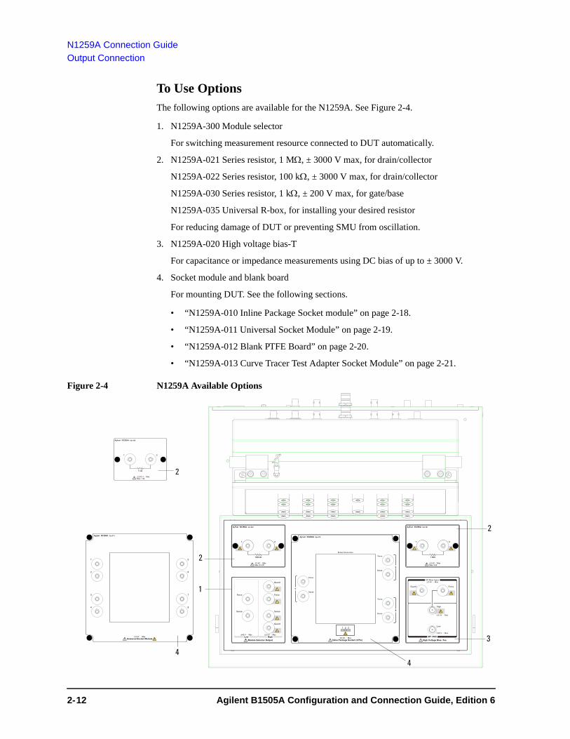
The following options are available for the N1259A. See Figure 2-4.
1. N1259A-300 Module selector
For switching measurement resource connected to DUT automatically.
2. N1259A-021 Series resistor, 1 M, ± 3000 V max, for drain/collector
N1259A-022 Series resistor, 100 k, ± 3000 V max, for drain/collector
N1259A-030 Series resistor, 1 k, ± 200 V max, for gate/base
N1259A-035 Universal R-box, for installing your desired resistor
For reducing damage of DUT or preventing SMU from oscillation.
3. N1259A-020 High voltage bias-T
For capacitance or impedance measurements using DC bias of up to ± 3000 V.
4. Socket module and blank board
For mounting DUT. See the following sections.
• “N1259A-010 Inline Package Socket module” on page 2-18.
• “N1259A-011 Universal Socket Module” on page 2-19.
• “N1259A-012 Blank PTFE Board” on page 2-20.
• “N1259A-013 Curve Tracer Test Adapter Socket Module” on page 2-21.
Figure 2-4 N1259A Available Options
2
1
2
3
4
High Voltage Bias–Tee
Guard
Module Selector Output
Force
Sense
Guard
Sense
Force
21
HighLow
21
±3 kV Max±40 V Max
N1259A Opt 022
±3 kV MaxMax: 6.4 W
±3 kV MaxMax: 9 W
N1259A Opt 021
N1259A Opt 010
Force
Sense
Force
Sense
Force
Sense1
2
3
1 2 3
±3 kV MaxInline Package Socket (3 Pin)
Kelvin Connection
MF CMU
DC Bias Input±3 kV Max
High
Low
Force
±3 kV Max
±25 V Max
Guard
4
2
51
2
3
4
6
7
8
N1259A Opt 011
±3 kV MaxUniversal Socket Module
21
±200 V MaxMax: 1 W
N1259A Opt 030
2- 12 Agilent B1505A Configuration and Connection Guide, Edition 6

N1259A Connection Guide
Output Connection
To Use Module Selector
The module selector is used to switch the measurement resource connected to a terminal of DUT. The measurement resource will be HP/MPSMU, HVSMU/HVMCU, or HC/DHCSMU connected to the Module Selector Input terminals (GNDU2, HPSMU3, HVSMU2, and HCSMU3 connectors, see Figure 2-1). The measurement resources must be connected to the Input terminals as shown in Table 2-2.
• Required parts:
N1254A-508 or N1254A-509 connection wire, 4 ea.
• Connection:
See Figure 2-5.
1. Connect a wire between the Low Force terminal and the low terminal of DUT.
2. Connect a wire between the Low Sense terminal and the low terminal of DUT.
3. Connect a wire between the High Force terminal and the high terminal of DUT.
4. Connect a wire between the High Sense terminal and the high terminal of DUT.
This connection is effective for all measurement performed by the modules connected to the module selector Input terminals. Connection change is not required. The module selector switching status is indicated by the Status indicator mounted on the front panel. See Figure 2-6 and Table 2-6 on page 2-14.
The Guard terminals must be opened. You may extend it as close as possible to a DUT terminal for reducing the leakage current of the extension cable.
Figure 2-5 Module Selector Connection Example
CAUTION Maximum current must be ± 30 A to prevent the module selector from performance degradation and failure.
High Voltage Bias–Tee
Guard
Module Selector Output
Force
Sense
Guard
Sense
Force
21
HighLow
21
±3 kV Max±40 V Max
N1259A Opt 022
±3 kV MaxMax: 6.4 W
±3 kV MaxMax: 9 W
N1259A Opt 021
N1259A Opt 010
Force
Sense
Force
Sense
Force
Sense1
2
3
1 2 3
±3 kV MaxInline Package Socket (3 Pin)
Kelvin Connection
MF CMU
DC Bias Input±3 kV Max
High
Low
Force
±3 kV Max
±25 V Max
Guard
Agilent B1505A Configuration and Connection Guide, Edition 6 2- 13
N1259A Connection Guide
Output Connection
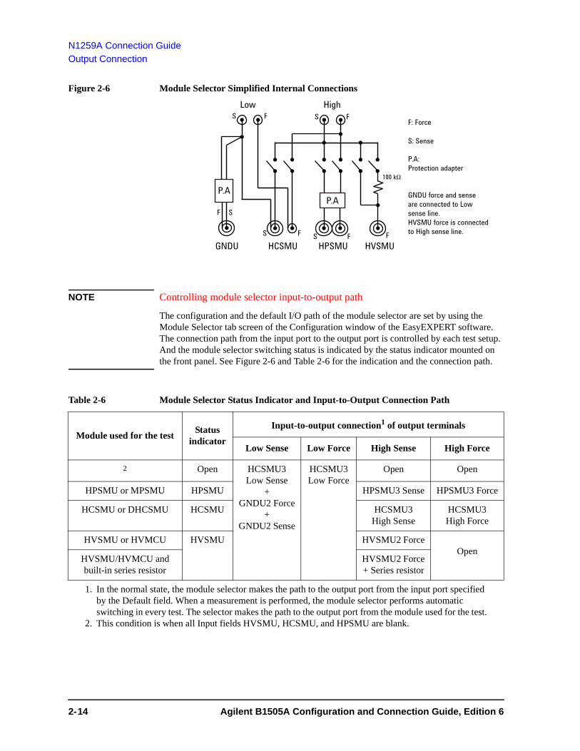
Figure 2-6 Module Selector Simplified Internal Connections
NOTE Controlling module selector input-to-output path
The configuration and the default I/O path of the module selector are set by using the Module Selector tab screen of the Configuration window of the EasyEXPERT software. The connection path from the input port to the output port is controlled by each test setup. And the module selector switching status is indicated by the status indicator mounted on the front panel. See Figure 2-6 and Table 2-6 for the indication and the connection path.
Table 2-6 Module Selector Status Indicator and Input-to-Output Connection Path
Low HighS F
S: Sense
F: Force
P.AP.A
GNDU HCSMU HPSMU HVSMUS FS F
SF
F
P.A:Protection adapter
S F
GNDU force and senseare connected to Lowsense line.HVSMU force is connected to High sense line.
100 kW
Module used for the testStatus
indicator
Input-to-output connection1 of output terminals
1. In the normal state, the module selector makes the path to the output port from the input port specified by the Default field. When a measurement is performed, the module selector performs automatic switching in every test. The selector makes the path to the output port from the module used for the test.
Low Sense Low Force High Sense High Force
2
2. This condition is when all Input fields HVSMU, HCSMU, and HPSMU are blank.
Open HCSMU3 Low Sense
+ GNDU2 Force
+ GNDU2 Sense
HCSMU3 Low Force
Open Open
HPSMU or MPSMU HPSMU HPSMU3 Sense HPSMU3 Force
HCSMU or DHCSMU HCSMU HCSMU3 High Sense
HCSMU3 High Force
HVSMU or HVMCU HVSMU HVSMU2 ForceOpen
HVSMU/HVMCU and built-in series resistor
HVSMU2 Force+ Series resistor
2- 14 Agilent B1505A Configuration and Connection Guide, Edition 6
N1259A Connection Guide
Output Connection
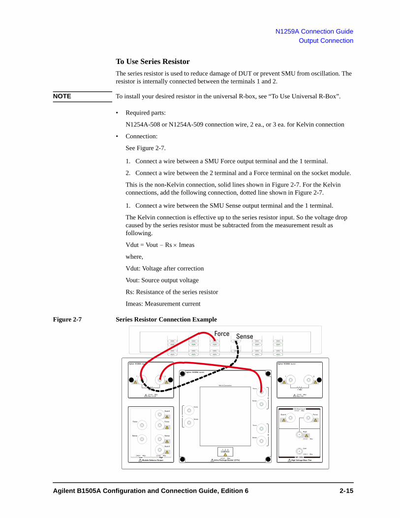
To Use Series Resistor
The series resistor is used to reduce damage of DUT or prevent SMU from oscillation. The resistor is internally connected between the terminals 1 and 2.
NOTE To install your desired resistor in the universal R-box, see “To Use Universal R-Box”.
• Required parts:
N1254A-508 or N1254A-509 connection wire, 2 ea., or 3 ea. for Kelvin connection
• Connection:
See Figure 2-7.
1. Connect a wire between a SMU Force output terminal and the 1 terminal.
2. Connect a wire between the 2 terminal and a Force terminal on the socket module.
This is the non-Kelvin connection, solid lines shown in Figure 2-7. For the Kelvin connections, add the following connection, dotted line shown in Figure 2-7.
1. Connect a wire between the SMU Sense output terminal and the 1 terminal.
The Kelvin connection is effective up to the series resistor input. So the voltage drop caused by the series resistor must be subtracted from the measurement result as following.
Vdut = Vout - Rs Imeas
where,
Vdut: Voltage after correction
Vout: Source output voltage
Rs: Resistance of the series resistor
Imeas: Measurement current
Figure 2-7 Series Resistor Connection Example
Agilent B1505A Configuration and Connection Guide, Edition 6 2- 15

N1259A Connection Guide
Output Connection
To Use Universal R-Box
The universal R-box is a blank box, kind of a do-it-yourself kit for installing your desired resistor.
To install the resistor, see the following simple instruction.
• Required parts:
your desired resistor, adequate rating
hexlobe (torx type) screwdriver T-10
label, for noting the resistance value
• Instruction:
1. Remove the cover bottom of the blank box.
2. Solder the resistor between the terminals 1 and 2.
To prevent discharge and any accident, make enough space between the resistor leads and the shield or chassis. For example, make space of about 6 mm from the leads for maximum 3000 V output.
3. Reattach the cover.
Make enough space between the resistor leads and the cover.
4. Write the resistance value in the label.
5. Affix the label to the top cover.
Figure 2-8 To Install Resistor in the N1259A-035 Universal R-Box
2- 16 Agilent B1505A Configuration and Connection Guide, Edition 6

N1259A Connection Guide
Output Connection
To Use High Voltage Bias-T
The high voltage bias-T is used to perform capacitance or impedance measurements using DC bias of up to ± 3000 V. The bias-T High terminal is internally connected to the MF CMU Hpot and Hcur input connectors. And the bias-T Low terminal is internally connected to the MF CMU Lpot and Lcur input connectors.
• Required parts:
N1254A-512 SHV(plug)-SHV(plug) cable, 2 ea.
N1254A-513 SHV(jack)-banana adapter, 2 ea.
N1254A-508 or N1254A-509 connection wire, 2 ea.
• Connection:
See Figure 2-9.
1. Attach the SHV-banana adapter to the SHV cable, and make two cables.
2. Connect a cable (solid line) between the bias-T Low terminal and the low terminal of DUT.
3. Connect a cable (solid line) between the bias-T High terminal and the high terminal of DUT.
4. Connect a wire (dotted line) between a SMU Force output terminal and the DC Bias Input High terminal. Use MPSMU for DC bias of up to ± 100 V, HPSMU for ± 200 V, or HVSMU for ± 3000 V.
5. Connect a wire (dotted line) between the SMU Guard output terminal and the DC Bias Input Guard terminal.
Figure 2-9 High Voltage Bias-T Connection Example
Agilent B1505A Configuration and Connection Guide, Edition 6 2- 17

N1259A Connection Guide
Output Connection
N1259A-010 Inline Package Socket module
This module provides a socket used for connecting three-terminal inline packaged device and three couples of the Force and Sense terminals. Socket module internal connection is shown in Figure 2-10.
Short bar is furnished with the module. It is used for performing the short correction before the impedance measurement. Set the short bar before the short correction and remove it after the correction.
To use this module, see the following simple instruction.
• Required parts:
N1254A-508 or N1254A-509 connection wire, 1 ea. for one connection
• Instruction:
1. Attach the socket module to the test fixture.
2. Connect wires between the socket module terminals and the fixture output terminals.
For making the Kelvin connection, Force and Sense must be connected to Force and Sense of the socket module respectively.
If MCSMU, HCSMU, or DHCSMU is used, High Force and Sense must be connected to Force and Sense used for the high terminal of a device under test (DUT), respectively. Low Force and GNDU Force must be connected to Force used for the low terminal of the DUT, and Low Sense and GNDU Sense must be connected to Sense used for the low terminal of the DUT. See Figure 2-3 for example.
3. Set the DUT on the socket.
4. Close the fixture cover and perform measurement.
CAUTION Do not apply voltage/current over the maximum limit of the socket module.
Figure 2-10 Inline Package Socket Module
2Force
Sense
3Force
Sense
1Force
Sense
165 mm
165 mm
3.48 mm1.78 mm
14 mm
Height: 34 mm(45 mm including terminal)(58 mm including socket)
Maximum voltage: 3000 VMaximum current: 40 A pulse, 2 A dc
2- 18 Agilent B1505A Configuration and Connection Guide, Edition 6

N1259A Connection Guide
Output Connection
N1259A-011 Universal Socket Module
This is a blank module, kind of a do-it-yourself kit for supporting variety of packaged devices. This module can be used by mounting your desired socket or packaged device and making connections same as the N1259A-010 Inline Package Socket Module.
To use this module, see the following simple instruction. For the component locations and dimensions, see Figure 2-11. Also see “N1259A-010 Inline Package Socket module” on page 2-18 to perform measurement.
• Required parts:
blank board suitable for mounting the socket or packaged device
screw M3, 4 ea., for fixing the blank board on the socket module
wire, adequate length and quantity, for making connections
hexlobe (torx type) screwdriver T-10
socket, if you use, and packaged device under test (DUT)
• Instruction:
1. Cut the blank board in 104 mm 89 mm square.
2. Make four screw holes on the board. The holes should be 4.5 mm inside from the edge.
3. Fix the board to the blank module.
4. Remove the cover bottom of the blank module.
5. Mount the socket or DUT on the board and solder wire between its terminals and the blank module terminals 1 to 8.
Make enough space between the socket/DUT terminal and the shield/chassis, for example, about 1 mm for maximum 200 V output and 6 mm for 3000 V, to prevent discharge and any accident.
6. Reattach the cover.
Figure 2-11 Universal Socket Module
90 mm
(Nut pitch: 95 mm)165 mm
165 mm
129 mm
160 mm
105 mm
Height: 34 mm (45 mm including terminal)
(Nut pitch: 80 mm)
21
34
56
78
Agilent B1505A Configuration and Connection Guide, Edition 6 2- 19

N1259A Connection Guide
Output Connection
N1259A-012 Blank PTFE Board
This is an insulation board used for placing a DUT.
To use this board, see the following simple instruction.
• Required parts:
N1254A-508 or N1254A-509 connection wire, 1 ea. for one connection
N1254A-510 dolphin clip adapter or N1254A-511 cable lag adapter, 1 ea. for one connection. Select one suitable for your DUT. See Table 2-5.
• Instruction:
1. Attach the blank PTFE board to the test fixture.
2. Connect adapters directly to the DUT and put it on the blank PTFE board.
3. Connect wires between the adapters and the fixture output terminals.
For making the Kelvin connection, Force and Sense must be connected together at the device terminal.
If MCSMU, HCSMU, or DHCSMU is used, High Force and Sense must be connected to the high terminal of a device under test (DUT). Low Force, Low Sense, GNDU Force, and GNDU Sense must be connected to the low terminal of the DUT. See Figure 2-3 for reference.
4. Make sure the DUT location. The DUT must be placed on the blank PTFE board properly.
Make enough space between the adapters, also between the adapter of high side and the shield/chassis, for example, about 1 mm for maximum 200 V output and 6 mm for 3000 V, to prevent discharge and any accident.
5. Close the fixture cover and perform measurement.
Figure 2-12 Blank PTFE Board
2- 20 Agilent B1505A Configuration and Connection Guide, Edition 6

N1259A Connection Guide
Output Connection
N1259A-013 Curve Tracer Test Adapter Socket Module
This module provides a socket available for connecting a test adapter designed for connecting to Tektronix 370 series curve tracers. Socket module internal connection is shown in Figure 2-13.
To use this module, see the following simple instruction.
• Required parts:
N1254A-508 or N1254A-509 connection wire, 1 ea. for one connection
• Instruction:
1. Attach the socket module to the test fixture.
2. Connect your test adapter to the socket.
3. Connect wires between the socket module terminals and the fixture output terminals.
For making the Kelvin connection, Force and Sense must be connected to Force and Sense of the socket module respectively.
If MCSMU, HCSMU, or DHCSMU is used, High Force and Sense must be connected to Force and Sense used for the high terminal of a device under test (DUT), respectively. Low Force and GNDU Force must be connected to Force used for the low terminal of the DUT, and Low Sense and GNDU Sense must be connected to Sense used for the low terminal of the DUT. See Figure 2-3 for example.
4. Set the DUT on your test adapter.
5. Close the fixture cover and perform measurement.
CAUTION Do not apply voltage/current over the maximum limit of the socket module.
Figure 2-13 Curve Tracer Test Adapter Socket Module
Collector / Drain Emi er / Source Base / Gate
Agilent N1259A Opt 013
Force Sense Force Sense Force Sense
Curve Tracer Test Adapter Socket
1 2
5 6
43
Internal connection1: Collector/Drain Force2: Collector/Drain Source3: Emitter/Source Force4: Emitter/Source Source5: Base/Gate Force6: Base/Gate Source
A
B C
Maximum voltage: 3000 VMaximum current: A-Force: 500 A pulse, 39 A dcA-Sense: 40 A pulse, 2 A dcB-Force: 500 A pulse, 39 A dcB-Sense: 40 A pulse, 2 A dcC-Force: 40 A pulse, 2 A dcC-Sense: 40 A pulse, 2 A dc
Agilent B1505A Configuration and Connection Guide, Edition 6 2- 21

N1259A Connection Guide
Output Connection
2- 22 Agilent B1505A Configuration and Connection Guide, Edition 6
3 N1265A Connection Guide

N1265A Connection Guide
This chapter describes the required information for connecting Agilent B1505A, N1265A, and a device under test (DUT).
• “Input Connection”
• “Output Connection”
The N1265A is a test fixture which contains the current expander to enable 500 A or 1500 A (option N1265A-015) output and measurement, and contains the selector to switch the measurement resource connected to the DUT.
The current expander is used to configure ultra high current unit (UHCU).
The selector is used to switch the measurement resource connected to the DUT. The measurement resource will be the UHCU, HVSMU/HVMCU, or HP/MPSMU. The selector output can be extended to your prober station by using the N1254A-524 ultra high current prober system cable.
The N1265A also provides the connection paths for UHVU, MFCMU via bias-tee, and HP/MP/HC/MC/DHCSMU.
• Dimensions: 420 mm (W) 285 mm (H) 575 mm (D)
• Weight: 30.0 kg
• Maximum volt-amps: 400 VA
WARNING To avoid electrical shock and instrument damage, turn the all instruments off before connecting or disconnecting measurement cable.
WARNING There are potentially hazardous voltages of up to ± 10 kV (UHVU), ± 3000 V (HVSMU), ± 2200 V (HVMCU), ± 200 V (HPSMU), or ± 100 V (MPSMU) at the High, Force, Guard, and Sense terminals. To prevent electrical shock, do not expose these lines.
WARNING To prevent electrical shock during use, connect the Interlock cable (see “To Connect Interlock Circuit” on page 3-5).
WARNING The B1505A and N1265A are heavy and require a two person lift.
CAUTION Do not grab the fixture cover when lifting the N1265A.
CAUTION Never connect the Guard terminal to any output, including circuit common, chassis ground, or any other guard terminal. Connecting anything may damage the instrument.
CAUTION Never connect the UHVU High, HVMCU High, and HVSMU Force and Guard terminals to any output, including circuit common, chassis ground, or any other measurement resource such as SMU. Connecting other measurement resource may damage the connected one.
CAUTION Never connect the UHVU Low terminal to any other measurement resource except for the N1269A or N1265A-040 adapter. Connecting other measurement resource may damage the connected one.
3- 2 Agilent B1505A Configuration and Connection Guide, Edition 6

N1265A Connection Guide
NOTE Using Universal R-box and Universal Socket Module
The universal R-box and the universal socket module are the do-it-yourself kit for installing a resistor you want or mounting a socket you want.
You need to prepare the hexlobe (torx type) screwdriver T-10 to remove the cover.
After installing a resistor or mounting a socket, reattach the cover. Do not use the universal R-box and the universal socket module under the condition that the cover is removed.
Agilent B1505A Configuration and Connection Guide, Edition 6 3- 3

N1265A Connection Guide
Input Connection
Input ConnectionPrepare the required cables listed in the following tables and connect them between the B1505A terminals and the relative N1265A terminals. Table 3-2 shows the connections without HVMCU and UHVU. Table 3-3 shows the additional connections for using HVMCU. And Table 3-4 shows the additional connections for using UHVU. For the additional information on the HVMCU, see “To Connect HVSMU Current Expander” on page 4-33. For the additional information on the UHVU, see “To Connect Ultra High Voltage Expander” on page 4-37.
Figure 3-1 N1265A Input Connectors on Rear Panel
SMU 1 ([1], [2]), 2 ([3], [4]), and 3 ([5], [6]) connectors are used for connecting the MPSMU, HPSMU, or MCSMU. Also SMU 3 ([5], [6]) connectors can be used for connecting HCSMU or DHCSMU. See Table 3-1 for the SMU signal assigned to the SMU input connector by the type of the connected SMU.
The connectors [1], [3], and [5] are for connecting Force, and the connectors [2], [4], and [6] are for connecting Sense of the measurement resource connected to the connectors [1], [3], and [5] respectively.
For connecting HP/MPSMU, the connectors [2], [4], and [6] can be also used to connect Force of other SMU for non-Kelvin connection.
NOTE For connecting MFCMU, use N1300A-001 CMU cable, N1260A high voltage bias-tee, and N1254A-518 SHV(plug)-SHV(plug) cable.
UHV Bias Tee SMU SMU1 2 3
±10 kV Max ±3 kV Max ±200 V Max 1 A±200 V Max
2 A dc 40 A Pulse
To avoid electrical shock and instrument damage,do not remove the cables during operation.
High
Low Low
High
To Use HPSMU/MPSMUConnect the N1261A-001 protection adapter between the SMUconnectors and HPSMU/MPSMU to prevent damage to the SMU.
CAUTION
KCC-REM-ATi-1H-ParaINSTR
Output Input
HVSMU V Control I ControlMCSMU/HCSMU MCSMU/HCSMU
SMU
GNDU
Force
Sense
Force
Sense
Force
Sense
Force
SenseN10149
LINE100-240 V
50/60 Hz400 VA Max
UHC Input
Interlock
GateDigital I/O
Selector Input
±3 kV Max ±200 V Max ±40 V Max ±40 V Max
3- 4 Agilent B1505A Configuration and Connection Guide, Edition 6

N1265A Connection Guide
Input Connection
CAUTION The GNDU can sink current of up to 4.2 A.
Use 16493L GNDU cable to connect the GNDU to an adapter, a test fixture, or a connector plate.
Do not use normal triaxial cable (16494A) because the maximum current rating of the cable is 1 A.
NOTE Do not put any conductor on the HCSMU Low Force and Low Sense terminals, outer conductor of the coaxial connectors. Putting conductor of circuit common, chassis ground, or any potential on causes the measurement error.
NOTE Dual HCSMU (DHCSMU)
DHCSMU can be configured by two HCSMU modules installed in one B1505A and connected to the 16493S-021 Dual HCSMU combination adapter. See “To Connect Dual HCSMU Adapter” on page 4-19 for connection. The adapter output connectors are compatible with HCSMU.
NOTE The B1505A needs to automatically detect and register the CMU cable type during boot process.
Table 3-1 SMU Input Connectors and Signals by SMU Type
To Connect Interlock Circuit
The B1505A provides the Interlock connector to prevent you from receiving an electrical shock from high voltage (more than ± 42 V). If the interlock circuit is open, the B1505A cannot apply high voltage more than ± 42 V.
When using the N1265A test fixture, connect the 16493J interlock cable between the Interlock connectors of the B1505A and the N1265A. If the N1268A expander is used, connect the cables between the B1505A and the N1268A, and between the N1268A and the N1265A.
Connected SMU
Connection method
1 2 3
[1] [2] [3] [4] [5] [6]
MPSMU Kelvin Force Sense Force Sense Force Sense
non-Kelvin Force Force Force Force Force Force
HPSMU Kelvin Force Sense Force Sense Force Sense
non-Kelvin Force Force Force Force Force Force
MCSMU Kelvin Force Sense Force Sense Force Sense
HCSMU Kelvin NA NA Force Sense
DHCSMU Kelvin NA NA Force Sense
Agilent B1505A Configuration and Connection Guide, Edition 6 3- 5

N1265A Connection Guide
Input Connection
Table 3-2 To Connect between B1505A and N1265A, without HVMCU and UHVU
B1505A terminals Required cables N1265A terminals
Interlock 16493J Interlock cable, 3 m or 1.5 m, 1 ea. Interlock1
GNDU 16493L GNDU cable, 3 m or 1.5 m, 1 ea. GNDU2
HVSMU Force 16493T HVSMU cable, 3 m or 1.5 m, 1 ea. Selector Input
HVSMU3
HPSMU or
MPSMU
Force 16494A Triaxial cable, 3 m or 1.5 m, 1 ea., for the non-Kelvin connection, connect it between the Force connectors.
For the Kelvin connection, prepare additional one more cable and connect it between the Sense connectors.
Selector Input SMU
Force
Sense Sense
MCSMU4 Force 16494A Triaxial cable, 3 m or 1.5 m, 1 ea. UHC Input
V Control
Force
Sense 16494A Triaxial cable, 3 m or 1.5 m, 1 ea. Sense
MCSMU4 Force 16494A Triaxial cable, 3 m or 1.5 m, 1 ea. UHC Input
I Control
Force
Sense 16494A Triaxial cable, 3 m or 1.5 m, 1 ea. Sense
MCSMU4 Force 16494A Triaxial cable, 3 m or 1.5 m, 1 ea. Gate Force
Sense 16494A Triaxial cable, 3 m or 1.5 m, 1 ea. Sense
MCSMU or
HPSMU or
MPSMU
Force To connect MCSMU, use two 16494A cables, 3 m or 1.5 m.
To connect HP/MPSMU, use N1261A-001 protection adapter and four 16494A triaxial cables for Kelvin connection or two 16494A cables for non-Kelvin connection. Recommended cable length is 1.5 m. See “To Connect Protection Adapter” on page 4-22 for protection adapter.
SMU 1/2/3
See Table 3-1.
[1]/[3]/[5]
Sense [2]/[4]/[6]
HCSMU or
DHCSMU
Force For HCSMU, 16493S HCSMU cable, 3 m or 1.5 m, 1 ea., N1254A-103 adapter for Force, and N1254A-517 adapter for Sense
For DHCSMU, 16493S HCSMU cable, 3 m or 1.5 m, 1 ea., 16493S-021 Dual HCSMU adapter, N1254A-103 adapter for Force, and N1254A-517 adapter for Sense. See “To Connect 16493S-021” on page 4-21 for Dual HCSMU adapter.
SMU 3 [5]
Sense [6]
MFCMU Hpot N1300A-001 CMU cable 1 ea., N1260A high voltage bias-tee 1 ea., and N1254A-518 SHV(plug)-SHV(plug) cable 2 ea. See “To Connect High Voltage Bias Tee” on page 4-24 for bias-tee.
It is not needed to connect the ground wire extended from the CMU cable.
Bias Tee High
Hcur
Lcur Low
Lpot
3- 6 Agilent B1505A Configuration and Connection Guide, Edition 6

N1265A Connection Guide
Input Connection
WARNING Connect a wire from an electrical ground (safety ground) to the earth terminal.
Table 3-3 To Connect between B1505A and N1265A for using HVMCU (N1266A)
Digital I/O 16493G Digital I/O connection cable, 3 m or 1.5 m, 1 ea. Digital I/O Input
Power cable, 1 ea., for connecting to power line LINE
Wire, 1 ea., for earthing (earth)
1. If the N1268A expander is used, connect the 16493J-001 cable from the N1268A Interlock Output.2. If the N1266A expander is used, connect the 16493L-001 cable from the N1266A Output Low.3. If the N1266A expander is used, connect the 16493T-001 cable from the N1266A Output High.4. HCSMU is substitutable. Then use 16493S HCSMU cable, N1254A-103 adapter for Force, and
N1254A-517 adapter for Sense.
B1505A terminals Required cables N1265A terminals
B1505A terminals Required cables N1266A terminals1
1. To configure HVMCU, the N1266A current expander is required.
GNDU 16493L-001 GNDU cable, 1.5 m, 1 ea. GNDU
HVSMU Force 16493T-001 HVSMU cable, 1.5 m, 1 ea. HVSMU
MCSMU2
2. HCSMU is substitutable. Then use 16493S HCSMU cable, N1254A-103 adapter for Force, and N1254A-517 adapter for Sense.
Force 16494A-001 Triaxial cable, 1.5 m, 1 ea. I Control Force
Sense 16494A-001 Triaxial cable, 1.5 m, 1 ea. Sense
MCSMU2 Force 16494A-001 Triaxial cable, 1.5 m, 1 ea. V Control Force
Sense 16494A-001 Triaxial cable, 1.5 m, 1 ea. Sense
N1266A terminals Required cables N1265A terminals
Output High 16493T-001 HVSMU cable, 1.5 m, 1 ea. Selector Input HVSMU
Low 16493L-001 GNDU cable, 1.5 m, 1 ea. GNDU
Digital I/O Input 16493G-001 Digital I/O connection cable, 1.5 m, 1 ea. Digital I/O Output
LINE Power cable, 1 ea., for connecting to power line
Agilent B1505A Configuration and Connection Guide, Edition 6 3- 7

N1265A Connection Guide
Input Connection
Table 3-4 To Connect between B1505A and N1265A for using UHVU (N1268A)
WARNING Connect a wire from an electrical ground (safety ground) to the earth terminal.
B1505A terminals Required cables N1268A terminals1
1. To configure UHVU, the N1268A ultra high voltage expander is required.
Interlock 16493J-001 Interlock cable, 1.5 m, 1 ea. Interlock Input
MCSMU Force 16494A-001 Triaxial cable, 1.5 m, 1 ea. I Control Force
Sense 16494A-001 Triaxial cable, 1.5 m, 1 ea. Sense
MCSMU2
2. HCSMU is substitutable. Then use 16493S HCSMU cable, N1254A-103 adapter for Force, and N1254A-517 adapter for Sense.
Force 16494A-001 Triaxial cable, 1.5 m, 1 ea. V Control Force
Sense 16494A-001 Triaxial cable, 1.5 m, 1 ea. Sense
N1268A terminals Required cables N1265A terminals
Interlock Output 16493J-001 Interlock cable, 1.5 m, 1 ea. Interlock
Output High UHV(plug)-UHV(plug) cable, 1.5 m, 1 ea. (part of 16493V-001) UHV High
Low SHV(plug)-SHV(plug) cable, 1.5 m, 1 ea. (part of 16493V-001) Low
Digital I/O1
1. If the N1266A expander is used, connect the 16493G-001 cable from the N1266A Digital I/O Output.
16493G-001 Digital I/O connection cable, 1.5 m, 1 ea. Digital I/O Output
LINE Power cable, 1 ea., for connecting to power line
(earth) Wire, 1 ea., for earthing
3- 8 Agilent B1505A Configuration and Connection Guide, Edition 6

N1265A Connection Guide
Output Connection
Output ConnectionThe following parts are available for mounting a device under test (DUT) on the test fixture. Prepare the part suitable for your DUT and attach it to the test fixture. For details, see the following sections.
• “Inline Package Socket module (N1265A-010)” on page 3-17
• “Universal Socket Module (N1265A-011)” on page 3-18
• “Curve Tracer Test Adapter Socket Module (N1265A-013)” on page 3-19
• “Blank Silicon Plate (N1265A-002)” on page 3-20
Required parts for making the output connections are listed in the following table.
Table 3-5 Required Parts
Model/Option Description
N1254A-508 Connection wire, red, do not use with UHCU/UHVU
N1254A-509 Connection wire, black, do not use with UHCU/UHVU
N1254A-522 Connection wire, 2 ea., for using UHCU
N1254A-512 and
N1254A-513
SHV(plug)-SHV(plug) cable and SHV(jack)-banana adapter, for high voltage capacitance measurement
N1254A-510 Dolphin clip adapter, red and black, for using blank plate
N1254A-511 Cable lag adapter, red and black, for using blank plate
N1254A-520 UHV(plug)/SHV(plug) to no connector cables, 1 m, for using UHVU and blank plate
N1254A-523 Banana to no connector wire, 1 m, 2 ea., for using UHCU and blank plate
Agilent B1505A Configuration and Connection Guide, Edition 6 3- 9

N1265A Connection Guide
Output Connection
To Connect DUT
WARNING Set the instrument output off before connecting or disconnecting connection wire.
Press the B1505A front panel Stop key to set the module output off. And confirm that the B1505A front panel High Voltage indicator is not lit.
If the N1268A is used, press the High Voltage Enable switch to disable the high voltage output. And confirm that this red switch is not lit.
CAUTION Do not connect or disconnect your DUT while the B1505A is applying voltage or current. Otherwise, your DUT may be damaged.
CAUTION Do not touch the terminals of the cable and wire. Oil, perspiration, and dirt prevent good electrical contact, deteriorate insulation, and degrade measurement accuracy.
CAUTION Never connect the Selector Output High Force, High Sense, and Guard terminals, Bias Tee High connector, and UHV High connector to any output, including circuit common, chassis ground, or any other measurement resource such as SMU. Connecting other measurement resource may damage the connected one.
NOTE SMU Guard terminals and Selector Output Guard terminal
Guard must be opened. You may extend it as close as possible to a DUT terminal for reducing the leakage current of the extension cable.
1. Set the instrument output off.
2. Open the fixture cover.
3. Set a socket module on the test fixture.
For using the blank silicon plate, see “Blank Silicon Plate (N1265A-002)” on page 3-20.
4. Connect a wire to an output terminal. And repeat this for all terminals connected to the measurement resources to be used. See Figure 3-2 for the output terminals.
5. Connect the wire to the socket module input terminal.
Confirm the DUT pin assignment and the measurement resource to be used and complete the connections of all measurement terminals without making misconnection.
For using the inline package socket module, also see “Inline Package Socket module (N1265A-010)” on page 3-17.
For using the universal socket module, also see “Universal Socket Module (N1265A-011)” on page 3-18.
6. Set the DUT on the socket.
7. Close the fixture cover.
To apply more than ± 42 V, close the fixture cover. Otherwise, the interlock function will stop the B1505A output over ± 42 V.
3- 10 Agilent B1505A Configuration and Connection Guide, Edition 6

N1265A Connection Guide
Output Connection
WARNING Make sure that the cover is closed properly before starting measurement. Do not perform the measurement when a wire is protruding from the fixture cover.
Figure 3-2 N1265A Output Terminals
SMU Terminals
Output terminals internally connected to the SMU input connectors on the rear panel. Force, Sense, and Guard terminals for HP/MPSMU. High Force, Low Force, High Sense, and Low Sense for HC/MC/DHCSMU. See Table 3-6.
For using HP/MPSMU, Force must be connected to a terminal of a DUT. And Guard must be opened. You may extend it as close as possible to the DUT terminal for reducing the leakage current of the extension cable. Also, Force and Sense should be connected together at the device end for making the Kelvin connection effective for low resistance and high current measurements.
For using HC/MC/DHCSMU, High Force and High Sense must be connected together at the high terminal of a DUT. And Low Force and Low Sense must be connected together at the low terminal of the DUT. Also, Selector Output Low Force and Sense must be connected to the low terminal for connecting GNDU.
Use a MCSMU for the gate or base terminal of active device measurement using UHVU. Then attach the N1265A-040 protection adapter on the SMU terminals used for the MCSMU. This adapter is designed for protecting the MCSMU from ultra high voltage. Also see “Protection Adapter (N1265A-040)” on page 3-23.
NOTE Kelvin connection and non-Kelvin connection
If you want to simplify the connections, open the Sense terminals and use the Force terminals only. This is the non-Kelvin connection. The Force terminals can be used to apply and measure dc voltage or current. Note that the non-Kelvin connection is not available for GNDU and MCSMU/HCSMU/DHCSMU.
If you perform the low resistance measurement or the high current measurement, use the Kelvin connection which can reduce the residual resistance effects of the cables and contacts by connecting the Force and Sense lines together as close as possible to the DUT terminal. The Kelvin connection can be made on the test fixture as shown in Figure 3-3.
Force
Guard
Force
Guard
Force
Guard
Force
Guard
Force
Guard
Force
Guard
SenseForce SenseForce SenseForce
±200 V Max 1 ASMU SMU
±200 V Max 2 Adc 40 A Pulse
Force
High
Low
High
Low
High
Low
High
Low
±40 V Max 1 A PulseGuardSense
±3 kV Max ±3 kV MaxSelector Output
LowHigh
1 2
K Thermocouple±3 V Max
Bias Tee
High
Low
±10 kV MaxUHV
1 2 3
Gate
Agilent B1505A Configuration and Connection Guide, Edition 6 3- 11
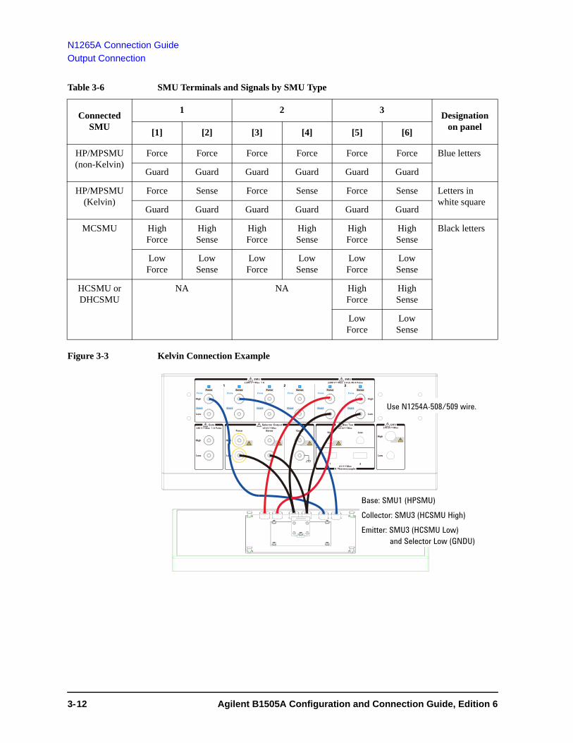
N1265A Connection Guide
Output Connection
Table 3-6 SMU Terminals and Signals by SMU Type
Figure 3-3 Kelvin Connection Example
Connected SMU
1 2 3Designation
on panel[1] [2] [3] [4] [5] [6]
HP/MPSMU (non-Kelvin)
Force Force Force Force Force Force Blue letters
Guard Guard Guard Guard Guard Guard
HP/MPSMU (Kelvin)
Force Sense Force Sense Force Sense Letters in white square
Guard Guard Guard Guard Guard Guard
MCSMU High Force
High Sense
High Force
High Sense
High Force
High Sense
Black letters
Low Force
Low Sense
Low Force
Low Sense
Low Force
Low Sense
HCSMU or DHCSMU
NA NA High Force
High Sense
Low Force
Low Sense
Force
Guard
Force
Guard
Force
Guard
Force
Guard
Force
Guard
Force
Guard
SenseForce SenseForce SenseForce
±200 V Max 1 ASMU SMU
±200 V Max 2 Adc 40 A Pulse
Force
High
Low
High
Low
High
Low
High
Low
±40 V Max 1 A PulseGuardSense
±3 kV Max ±3 kV MaxSelector Output
LowHigh
1 2
K Thermocouple±3 V Max
Bias Tee
High
Low
±10 kV MaxUHV
1 2 3
Gate
Base: SMU1 (HPSMU)Collector: SMU3 (HCSMU High)Emitter: SMU3 (HCSMU Low)
and Selector Low (GNDU)
Use N1254A-508/509 wire.
3- 12 Agilent B1505A Configuration and Connection Guide, Edition 6

N1265A Connection Guide
Output Connection
Gate Terminals
Output terminals internally connected to the Gate input connectors on the rear panel. High and Low terminals used for the gate drive.
Gate terminals are designed for using with the Selector Output terminals. See Figure 3-5. High should be connected to the gate or base terminal of a DUT. Low should be connected to the source or emitter terminal of the DUT. See Figure 3-4 for connection example.
CAUTION Open the Gate terminals for the ultra high voltage measurement using UHVU.
Figure 3-4 Gate and Selector Output Connection Example
Selector Output Terminals
Selector is used to switch the measurement resource connected to the DUT. See Figure 3-5 and Table 3-7 for the connection path. Also see Figure 3-4 for connection example.
CAUTION Open the terminals for the ultra high voltage measurement using UHVU.
1. Low Force and Low Sense output terminals
Force and Sense must be connected together at the low terminal of a DUT. Use the banana-banana wire (N1254A-522) to connect the Low Force terminal for performing the ultra high current measurement using UHCU.
2. High Force and High Sense output terminals
Force and Sense must be connected together at the high terminal of a DUT. Use the banana-banana wire (N1254A-522) to connect the High Force terminal for performing the ultra high current measurement using UHCU.
3. Guard terminal
Guard (high level) must be opened. You may extend it as close as possible to a DUT terminal for reducing the leakage current of the extension cable.
4. Chassis common terminal
Use for grounding or shielding.
Force
Guard
Force
Guard
Force
Guard
Force
Guard
Force
Guard
Force
Guard
SenseForce SenseForce SenseForce
±200 V Max 1 ASMU SMU
±200 V Max 2 Adc 40 A Pulse
Force
High
Low
High
Low
High
Low
High
Low
±40 V Max 1 A PulseGuardSense
±3 kV Max ±3 kV MaxSelector Output
LowHigh
1 2
K Thermocouple±3 V Max
Bias Tee
High
Low
±10 kV MaxUHV
1 2 3
Gate
Base: Gate High (MCSMU)Collector: Selector Output High Force and SenseEmitter: Selector Output Low Force and Sense and Gate Low (MCSMU)
Use N1254A-508/509 wire. Use N1254A-522 wire for High/Low Force.
Agilent B1505A Configuration and Connection Guide, Edition 6 3- 13

N1265A Connection Guide
Output Connection
NOTE Controlling selector input-to-output path
The configuration and the default I/O path of the selector are set by using the UHC Expander/Fixture tab screen of the Configuration window of the EasyEXPERT software. The connection path from the input port to the output port is controlled by each test setup. And the selector switching status is indicated by the status indicator mounted on the front panel. See Figure 3-5 and Table 3-7 for the indication and the connection path.
Figure 3-5 Built-in Selector Simplified Internal Connections
Table 3-7 Built-in Selector Status Indicator and Input-to-Output Connection Path
NOTE Selector may emit a noise sound during operation. However it is not abnormal status.
Measurement resource used for the test
Status indicator
Input-to-output connection1 of output terminals
1. In the normal state, the selector makes the path to the output port from the input port specified by the Default field. When a measurement is performed, the selector performs automatic switching in every test. The selector makes the path to the output port from the measurement resource used for the test.
Low Sense Low Force High Sense High Force
2
2. This condition is when the Default field is blank.
(off) Open Open Open Open
GNDU GNDU Sense GNDU Force Open Open
HPSMU or MPSMU SMU GNDU Sense GNDU Force SMU Sense SMU Force
UHCU UHC UHCU Low Sense
UHCU Low Force
UHCU High Sense
UHCU High Force
HVSMU or HVMCUHVSMU
GNDU Sense GNDU Force HVSMU Force Open
HVSMU/HVMCU and built-in series resistor
GNDU Sense GNDU Force HVSMU Force+ Series resistor
Open
Low HighSense Force
S: Sense
F: Force
P.A
GNDU
UHCU
SMU HVSMUS F
S FS F
F
P.A: Protection adapter
Sense Force
HVSMU force is connected to High sense line.
MCSMU MCSMUI-controlV-control
MCSMUFS
Low HighGate
100 kW
0 W10 W
100 Wor 1 kW
3- 14 Agilent B1505A Configuration and Connection Guide, Edition 6

N1265A Connection Guide
Output Connection
Bias Tee Terminals
Output terminals internally connected to the Bias Tee High and Low input connectors on the rear panel. The terminals should be connected to a DUT for performing the high voltage C-V measurement.
High and Low must be connected to the high and low terminals of a DUT respectively.
Use SHV(plug)-SHV(plug) cable (N1254A-512), 2 ea. and SHV(jack)-banana adapter (N1254A-513), 2 ea. for connection.
CAUTION Open the Bias Tee terminals for the ultra high voltage measurement using UHVU.
K Thermocouple Terminals
For connecting thermocouple (N1265A-041) to measure temperature around a DUT. Maximum temperature is approximately 180 C.
Agilent B1505A Configuration and Connection Guide, Edition 6 3- 15

N1265A Connection Guide
Output Connection
UHV Terminals
Output terminals internally connected to the UHV High and Low input connectors on the rear panel.
High and Low must be connected to the high and low terminals of a DUT respectively. Use the blank silicon plate and the UHV/SHV to no connector cables (N1254A-520) for connection. Figure 3-6 shows a connection example.
The ending of cables must be converted for connecting a DUT terminal. You may attach any adapter or solder a DUT terminal directly. See “Blank Silicon Plate (N1265A-002)” on page 3-20 and Figure 3-10 on page 3-21 for more information.
For the gate or base terminal of active device measurement using UHVU, use a MCSMU. Then attach the N1265A-040 protection adapter on the SMU terminals used for the MCSMU. This adapter is designed for protecting the MCSMU from ultra high voltage. Also see “Protection Adapter (N1265A-040)” on page 3-23 for the protection adapter.
Figure 3-6 UHV Connection Example
CAUTION Open the Gate terminals, the Selector Output terminals, and the Bias Tee terminals for the ultra high voltage measurement using the UHVU.
CAUTION Never connect the UHVU High terminal to any output, including circuit common, chassis ground, or any other measurement resource such as SMU. Connecting other measurement resource may damage the connected one.
Force
Guard
Force
Guard
Force
Guard
Force
Guard
Force
Guard
Force
Guard
SenseForce SenseForce SenseForce
±200 V Max 1 ASMU SMU
±200 V Max 2 Adc 40 A Pulse
Force
High
Low
High
Low
High
Low
High
Low
±40 V Max 1 A PulseGuardSense
±3 kV Max ±3 kV MaxSelector Output
LowHigh
1 2
K Thermocouple±3 V Max
Bias Tee
High
Low
±10 kV MaxUHV
1 2 3
Gate
High
Low
Force
High
Low
High
Low
±40 V Max 1 A PulseGuardSense
±3 kV MaxSelector OutputGate Selector OutputGate
Attach N1265A-040 Protection Adapter. Do not use Gate/Selector Output terminals.
SMU1 High
SMU1 Low UHVU High
UHVU Low
N1265A-002 Blank silicon plate
N1254A-520 SHV cableN1254A-508/509 wire
N1254A-520 UHV cable
N1254A-510/511 adapter
3- 16 Agilent B1505A Configuration and Connection Guide, Edition 6

N1265A Connection Guide
Output Connection
Inline Package Socket module (N1265A-010)
This module provides a socket used for connecting three-terminal inline packaged device and three couples of the Force and Sense terminals. Socket module internal connection is shown in Figure 3-7.
Short bar is furnished with the module. It is used for performing the short correction before the impedance measurement. Set the short bar before the short correction and remove it after the correction.
CAUTION Do not apply voltage/current over the maximum limit of the socket module.
Figure 3-7 Inline Package Socket Module
To use this module, see the following simple instruction.
1. Attach the socket module to the test fixture.
2. Connect wires between the socket module terminals and the fixture output terminals. Then use the following wire (furnished with the N1265A-010).
• 180 mm length wire (yellow) for Selector Output High/Low Force
• 180 mm length wire for Selector Output High/Low Sense
• 250 mm length wire for Gate, SMU, or chassis
For making the Kelvin connection, Force and Sense must be connected to Force and Sense of the socket module respectively.
For the high voltage capacitance measurement, use SHV(plug)-SHV(plug) cable (N1254A-512) and SHV(jack)-banana adapter (N1254A-513) for connection.
Selector Output and Gate should be connected as follows.
• Selector Output High to DUT high (ex. Collector/Drain)
• Selector Output Low to DUT low (ex. Emitter/Source)
• Gate High to DUT drive (ex. Base/Gate Force)
• Gate Low to DUT low (ex. Emitter/Source Force)
Collector / Drain Emi er / Source Base / Gate
Agilent N1265A Opt 010
Inline Package Socket (3 Pin)
1 2
5 6
43
3
F: ForceS: Sense
1
F S2
FS
165 mm
165 mm
3.48 mm1.78 mm
14 mm Height: 34 mm(45 mm including terminal)(58 mm including socket)
F S
1 32
Maximum current:1-F: 500 A pulse, 39 A dc1-S: 40 A pulse, 2 A dc2-F: 500 A pulse, 39 A dc2-S: 40 A pulse, 2 A dc3-F: 500 A pulse, 39 A dc3-S: 40 A pulse, 2 A dc
Maximum voltage: 3000 V
Agilent B1505A Configuration and Connection Guide, Edition 6 3- 17
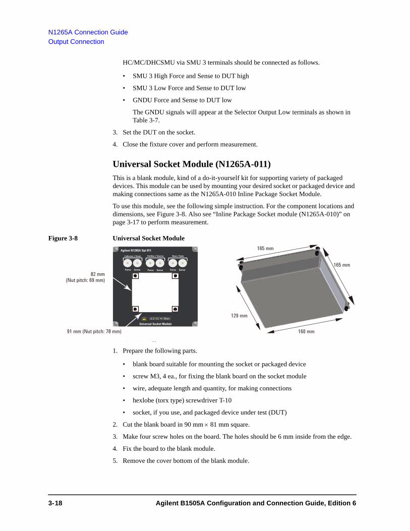
N1265A Connection Guide
Output Connection
HC/MC/DHCSMU via SMU 3 terminals should be connected as follows.
• SMU 3 High Force and Sense to DUT high
• SMU 3 Low Force and Sense to DUT low
• GNDU Force and Sense to DUT low
The GNDU signals will appear at the Selector Output Low terminals as shown in Table 3-7.
3. Set the DUT on the socket.
4. Close the fixture cover and perform measurement.
Universal Socket Module (N1265A-011)
This is a blank module, kind of a do-it-yourself kit for supporting variety of packaged devices. This module can be used by mounting your desired socket or packaged device and making connections same as the N1265A-010 Inline Package Socket Module.
To use this module, see the following simple instruction. For the component locations and dimensions, see Figure 3-8. Also see “Inline Package Socket module (N1265A-010)” on page 3-17 to perform measurement.
Figure 3-8 Universal Socket Module
1. Prepare the following parts.
• blank board suitable for mounting the socket or packaged device
• screw M3, 4 ea., for fixing the blank board on the socket module
• wire, adequate length and quantity, for making connections
• hexlobe (torx type) screwdriver T-10
• socket, if you use, and packaged device under test (DUT)
2. Cut the blank board in 90 mm 81 mm square.
3. Make four screw holes on the board. The holes should be 6 mm inside from the edge.
4. Fix the board to the blank module.
5. Remove the cover bottom of the blank module.
165 mm
165 mm
129 mm
160 mm
21
34
56
78
Collector / Drain Emi er / Source Base / Gate
Agilent N1265A Opt 011
Force Sense Force Sense Force Sense
Universal Socket Module
1 2
5 6
43
91 mm (Nut pitch: 78 mm)
(Nut pitch: 69 mm)82 mm
3- 18 Agilent B1505A Configuration and Connection Guide, Edition 6

N1265A Connection Guide
Output Connection
6. Mount the socket or DUT on the board and solder wire between its terminals and the blank module terminals.
Make enough space between the socket/DUT terminal and the shield/chassis, for example, about 1 mm for maximum 200 V output and 6 mm for 3000 V, to prevent discharge and any accident.
7. Reattach the cover.
Curve Tracer Test Adapter Socket Module (N1265A-013)
This module provides a socket available for connecting a test adapter designed for connecting to Tektronix 370B/371B curve tracers. Socket module internal connection is shown in Figure 3-9.
CAUTION Do not apply voltage/current over the maximum limit of the socket module.
Figure 3-9 Curve Tracer Test Adapter Socket Module
To use this module, see the following simple instruction.
1. Attach the socket module to the test fixture.
2. Connect your test adapter to the socket.
3. Connect wires between the socket module terminals and the fixture output terminals. Then use the following wire.
• N1254A-522 wire (yellow) for Selector Output High/Low Force
• N1254A-508 or 509 wire for Selector Output High/Low Sense, Gate, SMU, or chassis
For making the Kelvin connection, Force and Sense must be connected to Force and Sense of the socket module respectively.
For the high voltage capacitance measurement, use SHV(plug)-SHV(plug) cable (N1254A-512) and SHV(jack)-banana adapter (N1254A-513) for connection.
Selector Output and Gate should be connected as follows.
• Selector Output High to DUT high (ex. Collector/Drain)
• Selector Output Low to DUT low (ex. Emitter/Source)
Collector / Drain Emi er / Source Base / Gate
Agilent N1265A Opt 013
Force Sense Force Sense Force Sense
Curve Tracer Test Adapter Socket
1 2
5 6
43
Internal connection1: Collector/Drain Force2: Collector/Drain Source3: Emitter/Source Force4: Emitter/Source Source5: Base/Gate Force6: Base/Gate Source
Maximum voltage: 3000 VMaximum current: A-Force: 500 A pulse, 39 A dcA-Sense: 40 A pulse, 2 A dcB-Force: 500 A pulse, 39 A dcB-Sense: 40 A pulse, 2 A dcC-Force: 40 A pulse, 2 A dcC-Sense: 40 A pulse, 2 A dc
A
B C
Agilent B1505A Configuration and Connection Guide, Edition 6 3- 19

N1265A Connection Guide
Output Connection
• Gate High to DUT drive (ex. Base/Gate Force)
• Gate Low to DUT low (ex. Emitter/Source Force)
HC/MC/DHCSMU via SMU 3 terminals should be connected as follows.
• SMU 3 High Force and Sense to DUT high
• SMU 3 Low Force and Sense to DUT low
• GNDU Force and Sense to DUT low
The GNDU signals will appear at the Selector Output Low terminals as shown in Table 3-7.
4. Set the DUT on your test adapter.
5. Close the fixture cover and perform measurement.
Blank Silicon Plate (N1265A-002)
This is an insulation board used for placing a DUT. To use this board, see the following simple instruction.
1. Prepare a DUT and cable or wire, adequate length and quantity, for making connections. The following accessories are available.
• N1254A-520 UHV/SHV to no connector cables for UHV High/Low, see Figure 3-10 for connection. The cables need adapters or soldering to connect DUT.
• N1254A-522 banana-banana wire (yellow) or N1254A-523 banana to no connector wire (yellow) for Selector Output High/Low Force
• N1254A-508 or 509 connection wire for Selector Output High/Low Sense, Gate, SMU, and chassis
• N1254A-512 SHV cable and N1254A-513 adapter for capacitance measurement (Bias Tee terminals)
• N1254A-510 dolphin clip adapter or N1254A-511 cable lag adapter
2. Attach the blank silicon plate to the test fixture.
3. Connect cable/wire between the DUT and the fixture output terminals.
For making the Kelvin connection, Force and Sense must be connected to Force and Sense of the socket module respectively.
Selector Output and Gate should be connected as follows.
• Selector Output High to DUT high (ex. Collector/Drain)
• Selector Output Low to DUT low (ex. Emitter/Source)
• Gate High to DUT drive (ex. Base/Gate Force)
• Gate Low to DUT low (ex. Emitter/Source Force)
HC/MC/DHCSMU via SMU 3 terminals should be connected as follows.
• SMU 3 High Force and Sense to DUT high
• SMU 3 Low Force and Sense to DUT low
3- 20 Agilent B1505A Configuration and Connection Guide, Edition 6

N1265A Connection Guide
Output Connection
• GNDU Force and Sense to DUT low
The GNDU signals will appear at the Selector Output Low terminals as shown in Table 3-7.
4. Make sure the DUT location. The DUT must be placed on the blank silicon plate properly.
Make enough space between the cable ends, also between the high side cable end and the shield/chassis, for example, about 1 mm for maximum 200 V output, 6 mm for 3000 V, and 32 mm for 10 kV, to prevent discharge and any accident. Also the creepage distance must be more than 100 mm for 10 kV.
5. Close the fixture cover before starting measurement.
Figure 3-10 Space around Cable End
Universal R-Box (N1265A-035)
This is a blank box, kind of a do-it-yourself kit for installing a resistor you want. Generally, inserting a resister between SMU and DUT is effective for preventing SMU from oscillation. You can insert your desired resistor by using this box. This box is designed for using the MCSMU. See Figure 3-11 for connection example.
NOTE To install your desired resistor in the universal R-box, see “To Use Universal R-Box”.
The Kelvin connection is effective up to the R-box input. So the voltage drop caused by the series resistor must be subtracted from the measurement result as following.
Vdut = Vout - Rs Imeas
where,
Vdut: Voltage after correction
Vout: Source output voltage
Rs: Resistance of the series resistor
Imeas: Measurement current
To UHVU High To UHVU Low
DUT
Shield
Signal line
InsulatorSHV CableUHV Cable
Insulator
¡32 mm for 10 kV¡100 mm for 10 kV
Agilent B1505A Configuration and Connection Guide, Edition 6 3- 21

N1265A Connection Guide
Output Connection
Figure 3-11 Series Resistor Connection Example
To Use Universal R-Box
To install your desired resistor, see the following simple instruction.
• Required parts:
wire, adequate rating, length, and quantity
your desired resistor, adequate rating
hexlobe (torx type) screwdriver T-10
label, for noting resistance value
• Instruction:
1. Remove the cover of the universal R-box.
2. Solder the resistor and wire as shown below.
To prevent discharge and any accident, make enough space between the resistor leads and the shield or chassis. For example, make space of about 1 mm from the leads for maximum 200 V output.
Case 1: installing a series resistor on High, see Figure 3-12 on page 3-23.
• Connect a wire between Low Force and Low.
• Connect the resistor between High Force and High.
Case 2: installing a parallel resistor between High and Low
• Connect a wire between Low Force and Low.
• Connect a wire between High Force and High.
• Connect the resistor between High Force and Low Force.
Case 3: installing a series resistor on High and a parallel resistor between High and Low
• Connect a wire between Low Force and Low.
• Connect the parallel resistor between High and Low.
Force
Guard
Force
Guard
Force
Guard
Force
Guard
Force
Guard
Force
Guard
SenseForce SenseForce SenseForce
±200 V Max 1 ASMU SMU
±200 V Max 2 Adc 40 A Pulse
Force
High
Low
High
Low
High
Low
High
Low
±40 V Max 1 A PulseGuardSense
±3 kV Max ±3 kV MaxSelector Output
LowHigh
1 2
K Thermocouple±3 V Max
Bias Tee
High
Low
±10 kV MaxUHV
1 2 3
Gate
Attach N1265A-035 R-box.
Use N1254A-508/509 wire. Use N1254A-522 wire for High/Low Force.
High
Low
Base: SMU1 High (MCSMU)Collector: Selector Output High Force and SenseEmitter: Selector Output Low Force and Sense and SMU1 Low (MCSMU)
3- 22 Agilent B1505A Configuration and Connection Guide, Edition 6

N1265A Connection Guide
Output Connection
• Connect the series resistor between High Force and High.
Case 4: installing a series resistor on High and a parallel resistor between High Force and Low Force
• Connect a wire between Low Force and Low.
• Connect the parallel resistor between High Force and Low Force.
• Connect the series resistor between High Force and High.
3. Reattach the cover.
Make enough space between the resistor leads and the cover.
4. Write the resistance value in the label.
5. Affix the label to the top cover.
Figure 3-12 To Install Resistor in the N1265A-035 Universal R-Box, Connection for Case 1
Protection Adapter (N1265A-040)
This is the adapter for protecting SMU from ultra high voltage.
If a SMU is used for the gate drive when performing the ultra high voltage measurement using UHVU, this adapter must be connected to the SMU terminals for preventing SMU from damage. See Figure 3-6 for connection example.
This adapter is designed for using the MCSMU.
Container (N1265A-045)
This container can accommodate protection adapters and bias-tee which are used with the N1265A to make the measurement environment clean and safe.
Maximum superimposed load is 50 kg. The N1265A and the N1266A can be put on the top of the container.
Prober System Cable (N1254A-524)
This is the cable for extending the N1265A’s Selector Output and Gate terminals to a prober station. See “To Connect Ultra High Current Expander” on page 4-35 for more information.
CAUTION Do not apply voltage/current over the maximum limit of the cable. See Table 4-28.
High ForceLow Force
High SenseLow SenseHigh
Low
Agilent B1505A Configuration and Connection Guide, Edition 6 3- 23

N1265A Connection Guide
Output Connection
3- 24 Agilent B1505A Configuration and Connection Guide, Edition 6

4 Connection Guide for Wafer Prober and Your Own Test Fixture

Connection Guide for Wafer Prober and Your Own Test Fixture
This chapter describes how to make the measurement environment without using Agilent N1259A or N1265A test fixture.
For extending the measurement terminals to a device under test (DUT), you need to prepare connection cables, accessories, and your DUT interface such as wafer prober and your own test fixture. Also you need to install the interlock circuit and make the openings for the accessories on the shielding box of your DUT interface.
• “Connection Overview”
• “To Connect High Voltage R-Box”
• “To Connect HCSMU Adapter”
• “To Connect Dual HCSMU Adapter”
• “To Connect Protection Adapter”
• “To Connect High Voltage Bias Tee”
• “To Connect Module Selector”
• “To Connect HVSMU/HCSMU Fast Switch”
• “To Connect HVSMU Current Expander”
• “To Connect Ultra High Current Expander”
• “To Connect Ultra High Voltage Expander”
• “To Install an Interlock Circuit”
• “About Cable Connections”
For the dimensions of accessories, see Chapter 5, “Accessory Dimensions”.
WARNING To avoid electrical shock and instrument damage, turn the all instruments off before connecting or disconnecting measurement cable.
WARNING There are potentially hazardous voltages of up to ± 10 kV (UHVU), ± 3000 V (HVSMU), ± 2200 V (HVMCU), ± 200 V (HPSMU), or ± 100 V (MPSMU) at the High, Force, Guard, and Sense terminals. To prevent electrical shock, do not expose these lines.
WARNING To prevent electrical shock during use, install an interlock circuit (see p. 4-39) and connect the Interlock cable (see p. 4-41).
WARNING The B1505A, the N1265A ultra high current expander/fixture, and the N1268A ultra high voltage expander are heavy and require a two person lift.
CAUTION Never connect the Guard terminal to any output, including circuit common, chassis ground, or any other guard terminal. Connecting anything may damage the instrument.
NOTE To install the accessories, see Chapter 5, “Accessory Dimensions” and prepare the appropriate space in the shielding box of your DUT interface or make the openings for the accessories.
4- 2 Agilent B1505A Configuration and Connection Guide, Edition 6

Connection Guide for Wafer Prober and Your Own Test Fixture
NOTE Connecting the 16493G Digital I/O Connection Cable
If multiple accessories are used, the accessories must be connected together by using the Digital I/O cable. Then the cables must be connected from the B1505A to the accessories in the following sequence.
N1265A Ultra High Current Expander / Fixture, if used
N1266A HVSMU Current Expander, if used
N1268A Ultra High Current Expander, N1258A Module Selector, or N1259A test fixture
NOTE Using Universal R-box
The universal R-box is a blank box, kind of a do-it-yourself kit for installing a resistor you want.
You need to prepare the hexlobe (torx type) screwdriver T-10 to remove the cover.
After installing a resistor, reattach the cover. Do not use the universal R-box under the condition that the cover is removed.
NOTE Connecting or disconnecting the N1254A-524 Prober System Cable
The prober system cable is used to extend the UHCU (ultra high current unit) output to a prober station.
You need to prepare the box wrench (M5 hex) to connect or disconnect the system cable.
If the system cable is used, the 16493J interlock cable from the B1505A or the N1268A must be connected to the interlock circuit installed in the shielding box of the prober station. Do not connect the interlock cable to the N1265A.
Agilent B1505A Configuration and Connection Guide, Edition 6 4- 3

Connection Guide for Wafer Prober and Your Own Test Fixture
Connection Overview
Connection OverviewConnection image and requirements are shown in Table 4-1. Find and prepare required accessories and cables, and install and connect them to make the measurement environment. All available accessories are listed in Table 4-7.
CAUTION The GNDU can sink current of up to 4.2 A. Use 16493L GNDU cable to connect the GNDU to the N1261A-002/004.
Do not use normal triaxial cable (16494A) because the maximum current rating of the cable is 1 A.
NOTE Do not put any conductor on the HCSMU Low Force and Low Sense terminals, outer conductor of the coaxial connectors. Putting conductor of circuit common, chassis ground, or any potential on causes the measurement error.
NOTE Using Dual HCSMU (DHCSMU)
DHCSMU can be configured by two HCSMU modules installed in one B1505A and connected to the 16493S-020 Dual HCSMU Kelvin combination adapter or the 16493S-021 Dual HCSMU combination adapter. See “To Connect Dual HCSMU Adapter” for connection.
NOTE The B1505A needs to automatically detect and register the CMU cable type during boot process.
NOTE The N1258A module selector has built-in GNDU protection adapter, built-in HPSMU protection adapter, and built-in HCSMU Kelvin adapter. If you use the selector, you do not need the N1261A and 16493S-010/011 for the modules connected to it. See Table 4-3.
CAUTION Never connect the UHVU High, HVMCU High, and HVSMU Force and Guard terminals to any output, including circuit common, chassis ground, or any other measurement resource such as SMU. Connecting other measurement resource may damage the connected one.
CAUTION Never connect the UHVU Low terminal to any other measurement resource except for the N1269A or N1265A-040 adapter. Connecting other measurement resource may damage the connected one.
4- 4 Agilent B1505A Configuration and Connection Guide, Edition 6

Connection Guide for Wafer Prober and Your Own Test Fixture
Connection Overview
Table 4-1 Connection Image and Requirements
B1505A terminals
Required accessories and cablesConnection inside of
the shielding box
Interlock 16493J Interlock cable, 3 m or 1.5 m, 1 ea.
1252-1419 Interlock connector, 1 ea.
Interlock circuit
HVSMU
Also see Table 4-2 for HVMCU.
16493T HVSMU cable, 3 m or 1.5 m, 1 ea.
N1254A-501 HV(jack)-HV(jack) adapter, 1 ea.
N1262A-001/002 R-box and 16493T cable, optional
HV(plug) cable, 1 ea.
or SHV(plug) cable, 1 ea. for N1262A-001/002
MFCMU Hpot N1260A High voltage bias-T, 1ea.
N1300A CMU cable, 3 m or 1.5 m, 1 ea.
16493T HVSMU cable, 3 m or 1.5 m, 1 ea.
SHV(plug) cable, 3 ea.
High
Hcur Low
Lcur AC Guard
Lpot
HVSMU Force
HPSMU or
MPSMU
Force N1261A-001/003 HPSMU protection adapter, 1 ea.
16494A Triaxial cable, 3 m or 1.5 m, 2 ea. or 16493K Kelvin triaxial cable, 3 m or 1.5 m, 1 ea.
N1262A-010/011 R-box and 16494A/16493T cable, optional for non-Kelvin connection
Triaxial(m) cable, 2 ea. for N1261A-001 or
HV(plug) cable, 2 ea. for N1261A-003 or
Triaxial(m) cable, 1 ea. for N1262A-010 or
SHV(plug) cable, 1 ea. for N1262A-011
Sense
GNDU
Also see Table 4-2 for HVMCU.
N1261A-002/004 GNDU protection adapter, 1 ea.
16493L GNDU cable, 3 m or 1.5 m, 1 ea.
BNC(m) cable, 2 ea. for N1261A-002 or
SHV(plug) cable, 2 ea. for N1261A-004
HCSMU Force 16493S-010 HCSMU Kelvin adapter, 1 ea. or 16493S-011 HCSMU non-Kelvin adapter, 1 ea.
16493S HCSMU cable, 3 m or 1.5 m, 1 ea.
BNC(m) cable, 4 ea. for 16493S-010 or
BNC(m) cable, 2 ea. for 16493S-011
Sense
Shielding box
N1262A-010/011
DUT interface
N1260A
N1261A-002/004N1261A-001/003
16493S-010/011
Interlock circuit
N1254A, 16493U, or other cable
N1262A-001/002
16493S16493L
16494A/16493KN1300A, 16493T N1258A/N1267A
*3
*216493J16493T
N1266A
*1
*1: 16494A, 4 ea., 16493L, 16493T, and 16493G to configure HVMCU*2: 1252-1419*3: N1254A-501
B1505A
Agilent B1505A Configuration and Connection Guide, Edition 6 4- 5

Connection Guide for Wafer Prober and Your Own Test Fixture
Connection Overview
Also see the following tables.
• Table 4-2, “To Configure HVMCU by Using N1266A.”
• Table 4-3, “To Connect N1258A Module Selector.”
• Table 4-4, “To Connect N1267A Fast Switch.”
• Table 4-5, “To Make UHC Measurement Path.”
• Table 4-6, “To Make UHV Measurement Path.”
Table 4-2 To Configure HVMCU by Using N1266A
B1505A terminals Required cables N1266A terminals
MCSMU1
1. HCSMU is substitutable. Then use 16493S HCSMU cable, N1254A-103 adapter for Force, and N1254A-517 adapter for Sense.
Force 16494A-001 Triaxial cable, 1.5 m, 1 ea. I Control Force
Sense 16494A-001 Triaxial cable, 1.5 m, 1 ea. Sense
MCSMU1 Force 16494A-001 Triaxial cable, 1.5 m, 1 ea. V Control Force
Sense 16494A-001 Triaxial cable, 1.5 m, 1 ea. Sense
HVSMU Force 16493T-001 HVSMU cable, 1.5 m, 1 ea. HVSMU
GNDU 16493L-001 GNDU cable, 1.5 m, 1 ea. GNDU
Digital I/O 16493G-001 Digital I/O connection cable, 1.5 m, 1 ea. Digital I/O Input
N1266A terminals Required accessories and cables Connection inside of
the shielding box
Output High 16493T HVSMU cable, 3 m or 1.5 m, 1 ea.
N1254A-501 HV(jack)-HV(jack) adapter, 1 ea.
N1262A-001/002 R-box and 16493T cable, optional
HV(plug) cable, 1 ea.
or SHV(plug) cable, 1 ea. for N1262A-001/002
Low N1261A-002/004 GNDU protection adapter, 1 ea.
16493L GNDU cable, 3 m or 1.5 m, 1 ea.
BNC(m) cable, 2 ea. for N1261A-002 or
SHV(plug) cable, 2 ea. for N1261A-004
LINE Power cable, 1 ea., for connecting to power line
4- 6 Agilent B1505A Configuration and Connection Guide, Edition 6

Connection Guide for Wafer Prober and Your Own Test Fixture
Connection Overview
Table 4-3 To Connect N1258A Module Selector
B1505A terminals Required cables N1258A terminals
HPSMU or
MPSMU
Force 16494A Triaxial cable, 3 m or 1.5 m, 1 ea., for the non-Kelvin connection, connect it between the Force connectors.
For the Kelvin connection, prepare additional one more cable and connect it between the Sense connectors. Or use 16493K Kelvin triaxial cable instead of 16494A.
Use 16493K cable if the High output terminals are connected to the prober chuck.
HPSMU Force
Sense Sense
HCSMU or
DHCSMU
Force 16493S HCSMU cable, 3 m or 1.5 m, 1 ea. for HCSMU
16493S HCSMU cable, 3 m or 1.5 m, 2 ea. and 16493S-021 Dual HCSMU adapter, 1 ea. for DHCSMU
HCSMU Force
Sense Sense
HVSMU Force 16493T HVSMU cable, 3 m or 1.5 m, 1 ea. HVMCU can be used instead of HVSMU. See Table 4-2.
HVSMU
GNDU 16493L GNDU cable, 3 m or 1.5 m, 1 ea. Also see Table 4-2. GNDU
Digital I/O 16493G Digital I/O connection cable, 3 m or 1.5 m, 1 ea. Digital I/O
N1258A terminals Required cables/Description Connect to
Low Force Coaxial cable with BNC(m) connector. N1254A-503 can be used. DUT low terminal
(ex: source)1
1. Non-Kelvin connection is not allowed. GNDU Force and Sense are internally connected to Low Sense. See Table 4-22 on page 4-30.
Sense Coaxial cable with BNC(m) connector. N1254A-503 can be used.
High Force Coaxial cable with HV(plug) connector. N1254A-506 can be used. Use coaxial cable to minimize affect of inductance.
DUT high terminal
(ex: drain)1
Sense Triaxial cable with HV(plug) connector. N1254A-505 can be used.
LINE Power cable, 1 ea., for connecting to power line site AC power
Shielding boxB1505A
DUT interface N1258A
Interlock circuit
16493S16493T
SenseForce
Low
High
SenseForce *2
*1
*4
*1: 1252-1419*2: N1254A-506 or other cable, 1 ea.*3: N1254A-505 or other cable, 1 ea.*4: N1254A-503 or other cable, 2 ea.
16493G
16494A/16493K
16493L
*3
16493J
N1266A
*5
*5: 16494A, 4 ea., 16493L, 16493T, and 16493G to configure HVMCU.
Agilent B1505A Configuration and Connection Guide, Edition 6 4- 7

Connection Guide for Wafer Prober and Your Own Test Fixture
Connection Overview
Table 4-4 To Connect N1267A Fast Switch
B1505A terminals Required cables N1267A terminals
MCSMU Force 16494A Triaxial cable, 3 m or 1.5 m, 1 ea. MCSMU Force
Sense 16494A Triaxial cable, 3 m or 1.5 m, 1 ea. Sense
HCSMU Force 16493S HCSMU cable, 3 m or 1.5 m, 1 ea. for HCSMU HCSMU Force
Sense Sense
HVSMU Force 16493T HVSMU cable, 3 m or 1.5 m, 1 ea. HVSMU
GNDU 16493L GNDU cable, 3 m or 1.5 m, 1 ea. GNDU
N1267A terminals Required cables/Description Connect to
Low Force Coaxial cable with BNC(m) connector. N1254A-503 can be used. DUT low terminal (ex: source)
High Force Coaxial cable with HV(plug) connector. N1254A-506 can be used. Use coaxial cable to minimize affect of inductance.
DUT high terminal (ex: drain)
Shielding boxB1505A
DUT interface N1267A
Interlock circuit
16493T16493L
Low Force
High Force *2
*1
*3
*1: 1252-1419*2: N1254A-506 or other cable, 1 ea.*3: N1254A-503 or other cable, 2 ea.
16493S16494A
16493J
N1266A
*5
*5: 16494A, 4 ea., 16493L, 16493T, and 16493G to configure HVMCU.
4- 8 Agilent B1505A Configuration and Connection Guide, Edition 6

Connection Guide for Wafer Prober and Your Own Test Fixture
Connection Overview
Table 4-5 To Make UHC Measurement Path
B1505A terminals Required cables N1265A terminals
MCSMU1
1. HCSMU is substitutable. Then use 16493S HCSMU cable, N1254A-103 adapter for Force, and N1254A-517 adapter for Sense.
Force 16494A Triaxial cable, 1.5 m, 1 ea. UHC Input
I Control
Force
Sense 16494A Triaxial cable, 1.5 m, 1 ea. Sense
MCSMU1 Force 16494A Triaxial cable, 1.5 m, 1 ea. UHC Input
V Control
Force
Sense 16494A Triaxial cable, 1.5 m, 1 ea. Sense
MCSMU1 Force 16494A Triaxial cable, 1.5 m, 1 ea. Gate Force
Sense 16494A Triaxial cable, 1.5 m, 1 ea. Sense
GNDU 16493L GNDU cable, 1.5 m, 1 ea. Also see Table 4-2. GNDU
Digital I/O 16493G Digital I/O cable, 1.5 m, 1 ea. Also see Table 4-2. Digital I/O Input
Terminals Required cables/Description Connect to
Low Force Cable with banana connector. N1254A-523 can be used. DUT low terminal
(ex: source)2
2. Non-Kelvin connection is not allowed. GNDU Sense is internally connected to Low Sense.
Low Sense Coaxial cable with BNC(m) connector. N1254A-503 can be used.
High Force Cable with banana connector. N1254A-523 can be used. DUT high terminal
(ex: drain)2High Sense Triaxial cable with HV(plug) connector. N1254A-505 can be used.
Gate Coaxial cable with BNC(m) connector. N1254A-503 can be used. DUT gate or base
LINE Power cable, 1 ea., for connecting to power line site AC power
Earth Wire, 1 ea., for earthing site ground
B1505A Interlock 16493J Interlock cable, 3 m or 1.5 m, 1 ea., and 1252-1419 Interlock connector, 1 ea.
Interlock circuit
Shielding box
DUT interface
N1254A-524
Interlock circuit
SenseForceLow
HighSense
Force *2*1
*2
*3
16493J
N1265A
*1: 1252-1419*2: N1254A-523*3: N1254A-506*4: N1254A-503*5: 16494A, 6 ea., 16493L, and 16493G(needs more cables for using HVSMU/HVMCU or HP/MPSMU through selector of N1265A .)
*5 B1505A
*4
Gate *4
N1266A*6
*6: 16494A, 4 ea., 16493L, 16493T, and 16493G to configure HVMCU.
Agilent B1505A Configuration and Connection Guide, Edition 6 4- 9

Connection Guide for Wafer Prober and Your Own Test Fixture
Connection Overview
Table 4-6 To Make UHV Measurement Path
B1505A terminals Required cablesN1268A/N1269A
terminals
Interlock 16493J Interlock cable, 1.5 m, 1 ea. Interlock Input
MCSMU Force 16494A Triaxial cable, 1.5 m, 1 ea. I Control Force
Sense 16494A Triaxial cable, 1.5 m, 1 ea. Sense
MCSMU1
1. HCSMU is substitutable. Then use 16493S HCSMU cable, N1254A-103 adapter for Force, and N1254A-517 adapter for Sense.
Force 16494A Triaxial cable, 1.5 m, 1 ea. V Control Force
Sense 16494A Triaxial cable, 1.5 m, 1 ea. Sense
Digital I/O 16493G Digital I/O connection cable, 1.5 m, 1 ea. Digital I/O
MCSMU Force 16494A Triaxial cable, 1.5 m, 1 ea. N1269A Gate
Force
Sense 16494A Triaxial cable, 1.5 m, 1 ea. Sense
MCSMU Force 16494A Triaxial cable, 1.5 m, 1 ea. N1269A Chuck
Force
Sense 16494A Triaxial cable, 1.5 m, 1 ea. Sense
Terminals Required cables/Description Connect to
Interlock Output 16493J Interlock cable, 3 m or 1.5 m, 1 ea., and 1252-1419 Interlock connector, 1 ea.
Interlock circuit
Output Low SHV cable of 16494V, 3 m or 1.5 m, 1 ea. N1269A UHV Low
Output High UHV cable of 16494V, 3 m or 1.5 m, 1 ea., UHV adapter of N1254A-521, 1 ea., and UHV cable of N1254A-520
DUT high terminal (ex: drain)
LINE Power cable, 1 ea., for connecting to power line site AC power
Earth Wire, 1 ea., for earthing site ground
N1269A Source SHV cable of N1254A-520 DUT low terminal (ex: source)
N1269A Gate Coaxial cable with SHV connector or SHV cable of N1254A-520 DUT gate or base
N1269A Chuck Coaxial cable with SHV connector or SHV cable of N1254A-520 DUT chuck
Shielding box
DUT interface
N1269A
Interlock circuit
16494A
Source/Emitter
Chuck
Gate/Base
*2
*1
*4
*1: 1252-1419*2: UHV adapter of N1254A-521*3: UHV cable of N1254A-520*4: SHV cable of N1254A-520*5: 16494A, 4 ea., 16493J, and 16493G
*3
16493J*5
16493V (UHV) Drain/CollectorB1505A
N1268A
*4
*4
16493V (SHV)
4- 10 Agilent B1505A Configuration and Connection Guide, Edition 6
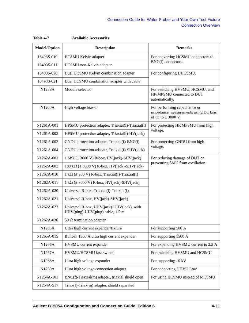
Connection Guide for Wafer Prober and Your Own Test Fixture
Connection Overview
Table 4-7 Available Accessories
Model/Option Description Remarks
16493S-010 HCSMU Kelvin adapter For converting HCSMU connectors to BNC(f) connectors.
16493S-011 HCSMU non-Kelvin adapter
16493S-020 Dual HCSMU Kelvin combination adapter For configuring DHCSMU.
16493S-021 Dual HCSMU combination adapter with cable
N1258A Module selector For switching HVSMU, HCSMU, and HP/MPSMU connected to DUT automatically.
N1260A High voltage bias-T For performing capacitance or impedance measurements using DC bias of up to ± 3000 V.
N1261A-001 HPSMU protection adapter, Triaxial(f)-Triaxial(f) For protecting HP/MPSMU from high voltage.
N1261A-003 HPSMU protection adapter, Triaxial(f)-HV(jack)
N1261A-002 GNDU protection adapter, Triaxial(f)-BNC(f) For protecting GNDU from high voltage.
N1261A-004 GNDU protection adapter, Triaxial(f)-SHV(jack)
N1262A-001 1 M (± 3000 V) R-box, HV(jack)-SHV(jack) For reducing damage of DUT or preventing SMU from oscillation.
N1262A-002 100 k (± 3000 V) R-box, HV(jack)-SHV(jack)
N1262A-010 1 k (± 200 V) R-box, Triaxial(f)-Triaxial(f)
N1262A-011 1 k (± 3000 V) R-box, HV(jack)-SHV(jack)
N1262A-020 Universal R-box, Triaxial(f)-Triaxial(f)
N1262A-021 Universal R-box, HV(jack)-SHV(jack)
N1262A-023 Universal R-box, UHV(jack)-UHV(jack), with UHV(plug)-UHV(plug) cable, 1.5 m
N1262A-036 50 termination adapter
N1265A Ultra high current expander/fixture For supporting 500 A
N1265A-015 Built-in 1500 A ultra high current expander For supporting 1500 A
N1266A HVSMU current expander For expanding HVSMU current to 2.5 A
N1267A HVSMU/HCSMU fast switch For switching HVSMU and HCSMU
N1268A Ultra high voltage expander For supporting 10 kV
N1269A Ultra high voltage connection adapter For connecting UHVU Low
N1254A-103 BNC(f)-Triaxial(m) adapter, triaxial shield open For using HCSMU instead of MCSMU
N1254A-517 Triax(f)-Triax(m) adapter, shield separated
Agilent B1505A Configuration and Connection Guide, Edition 6 4- 11

Connection Guide for Wafer Prober and Your Own Test Fixture
Connection Overview
N1254A-104 BNC(m)-Triaxial(f) adapter, triaxial shield open For using MCSMU instead of HCSMU
N1254A-106 BNC(f)-Triaxial(m) adapter, triaxial guard open For changing N1262A-010 triax to BNC
N1254A-402 Interlock micro switch For making interlock circuit. See “To Install an Interlock Circuit” on page 4-39.1252-1419 Interlock connector (6 pin, female)
1450-0641 LED (VF 2.1 V @ IF = 10 mA)
N1254A-500 HV(jack) connector, panel mount, for soldering For connecting HVSMU or accessory to your DUT interface.
N1254A-501 HV(jack)-HV(jack) adapter, panel mount
N1254A-502 HV(plug) connector, panel mount, for soldering
N1254A-503 BNC(m) to no connector coaxial cable, 1.5 m For connecting accessory to your DUT interface.
N1254A-504 HV(jack) to no connector coaxial cable, 1.5 m
N1254A-505 HV(plug) to no connector triaxial cable, 1.5 m
N1254A-506 HV(plug) to no connector coaxial cable, 1.5 m
N1254A-507 HV(plug)-HV(plug) coaxial cable, 1.5 m
N1254A-516 BNC(f)-(f)-(f) adapter
N1254A-518 SHV(plug)-SHV(plug) coaxial cable, 1.5 m For connecting N1260A to N1265A
N1254A-520 UHV(plug) to no connector cable, 1 m and SHV(plug) to no connector cable, 1 m
For connecting UHVU to your DUT interface.
N1254A-521 UHV(jack)-UHV(jack) adapter and SHV(jack)-SHV(jack) adapter
N1254A-523 Banana to no connector wire, 1 m, 2 ea. For connecting UHCU to prober station
N1254A-524 System cable for prober, 1.8 m
16493U-001 BNC(m)-BNC(m) coaxial cable, 1.5 m For connecting accessory to your DUT interface.
16493U-002 BNC(m)-BNC(m) coaxial cable, 3 m
1250-2405 BNC(m)-(f)-(f) adapter For connecting HCSMU adapter output and GNDU protection adapter output
8120-1838 or 8120-1839
BNC(m)-BNC(m) coaxial cable, 12 inch or 24 inch
Model/Option Description Remarks
4- 12 Agilent B1505A Configuration and Connection Guide, Edition 6

Connection Guide for Wafer Prober and Your Own Test Fixture
To Connect High Voltage R-Box
To Connect High Voltage R-BoxAgilent N1262A resistor box is used to reduce the risk of device breakdown or prevent SMU from oscillation. The N1262A should be installed in your DUT interface as shown in Table 4-1 on page 4-5.
N1262A-001: 1 M (± 3000 Vdc) resistor, HV(jack)-SHV(jack)
N1262A-002: 100 k (± 3000 Vdc) resistor, HV(jack)-SHV(jack)
N1262A-010: 1 k (± 200 Vdc) resistor, Triaxial(f)-Triaxial(f)
N1262A-011: 1 k (± 3000 Vdc) resistor, HV(jack)-SHV(jack)
N1262A-020: Universal R-box, Triaxial(f)-Triaxial(f)
N1262A-021: Universal R-box, HV(jack)-SHV(jack)
N1262A-023: Universal R-box, UHV(jack)-UHV(jack)
N1262A-036: 50 termination adapter
Universal R-box is kind of a do-it-yourself kit for installing a resistor you want. To install the resistor, see “To Use Universal R-Box” on page 4-14.
N1262A-036 termination adapter is a BNC(f)-BNC(m) adapter which contains 50 resistor between signal line and shield. If a SMU is used as the gate drive for the measurement using HVMCU, UHVU, or UHCU, the SMU may cause oscillation. Then this adapter should be connected between the gate drive output and a DUT terminal. This will be effective for preventing oscillation.
Table 4-8 To Connect N1262A Input
Connect from Required cables N1262A terminals
HVSMU Force 16493T-001 HVSMU cable, 1.5 m From HVSMU
N1261A-001 Force 16494A-001 Triaxial cable, 1.5 m, for N1262A-010 or N1262A-020
From SMU Force
N1261A-003 Force 16493T-001 HVSMU cable, 1.5 m
UHVU High UHV cable of 16493V-001 UHVU cable, 1.5 m From UHV
N 1262A O pt 001H igh V o ltage S eries R 1M
From H VS M U S igna l
C ircu itC om m on
3kV M ax
O utput
!!3kV M ax
A g ilen t
!!M ax : 9W
N 1262A O pt 001H igh V o ltage S eries R 1M
From H VS M U S igna l
C ircu itC om m on
S igna l
C ircu itC om m on
3kV M ax3kV M ax
O utput
!!3kV M ax
!!!3kV M ax3kV M ax
A g ilen t
!!!!!M ax : 9W
Agilent B1505A Configuration and Connection Guide, Edition 6 4- 13

Connection Guide for Wafer Prober and Your Own Test Fixture
To Connect High Voltage R-Box
Table 4-9 To Connect N1262A Output
Voltage drop caused by the R-box must be subtracted from the measurement result as following.
Vdut = Vout - Rs Imeas
where, Vdut: Voltage after correction, Vout: Source output voltage, Rs: Resistance of the series resistor, and Imeas: Measurement current
To Use Universal R-Box
To install your desired resistor, see the following simple instruction.
• Required parts:
wire, adequate rating, length, and quantity
your desired resistor, adequate rating
hexlobe (torx type) screwdriver T-10
label, for noting resistance value
• Instruction:
1. Remove the cover of the universal R-box.
2. Solder the resistor and wire as shown below.
To prevent discharge and any accident, make enough space between the resistor leads and the shield or chassis. For example, make space of about 1 mm from the leads for maximum 200 V output, 6 mm for 3000 V, and 32 mm for 10 kV.
Case 1: N1262A-020/021, see Figure 4-1.
• Connect a wire between a terminal and the center conductor of its near connector.
• Connect a wire between the other terminal and the center conductor of the other connector.
• Connect the resistor between the terminals.
Options Required cables/Description Connect to
N1262A-001 Coaxial cable with SHV(plug) connector. DUT terminal (ex: drain)
N1262A-002 Coaxial cable with SHV(plug) connector.
N1262A-010 Triaxial cable with Triaxial(m) connector. DUT terminal (ex: gate)
N1262A-011 Coaxial cable with SHV(plug) connector.
N1262A-020 Triaxial cable with Triaxial(m) connector.
N1262A-021 Coaxial cable with SHV(plug) connector.
N1262A-023 Coaxial cable with UHV(plug) connector.
4- 14 Agilent B1505A Configuration and Connection Guide, Edition 6

Connection Guide for Wafer Prober and Your Own Test Fixture
To Connect High Voltage R-Box
Case 2: N1262A-023, see Figure 4-2.
• Connect the resistor between the terminals.
3. Reattach the cover.
Make enough space between the resistor leads and the cover.
4. Write the resistance value in the label.
5. Affix the label to the top cover.
Figure 4-1 To Install Resistor in the N1262A-020 Universal R-Box
Figure 4-2 To Install Resistor in the N1262A-023 Universal R-Box
Agilent B1505A Configuration and Connection Guide, Edition 6 4- 15

Connection Guide for Wafer Prober and Your Own Test Fixture
To Connect HCSMU Adapter
To Connect HCSMU AdapterAgilent 16493S-010/011 HCSMU adapter is used to convert HCSMU connectors to BNC(f) connectors. The 16493S-010/011 should be installed near your DUT interface as shown in Table 4-1 on page 4-5.
16493S-010: Adapter for making the Kelvin connection of HCSMU path
16493S-011: Adapter for making the non-Kelvin connection of HCSMU path, available for the low current path such as the MOSFET gate terminal
Connection examples for using one HCSMU module are shown in Figure 4-3 for the Kelvin connection and in Figure 4-6 for the non-Kelvin connection. Also a connection example for using two HCSMU modules is shown in Figure 4-7.
NOTE Do not connect or put any conductor on the HCSMU Low Force and Low Sense terminals, outer conductor of the coaxial connectors. Connecting or putting conductor of circuit common, chassis ground, or any potential on causes the measurement error.
Table 4-10 To Connect 16493S-010/011 Input
Table 4-11 To Connect 16493S-010/011 Output
B1505A terminals Required cables Input terminals
HCSMU Force 16493S HCSMU cable, 3 m or 1.5 m From HCSMU
Force
Sense Sense
Output terminals Required cables/Description Connect to
Low Force Coaxial cable with BNC(m) connector. 16493U-001/002 or N1254A-503 can be used.
Low terminals must be grounded by using the GNDU. If you want to simplify the connection, connect the HCSMU adapter and the GNDU adapter as shown in Figure 4-4. It can remove the path from the GNDU adapter to the DUT interface.
DUT low terminal (ex: source)
Low Sense
High Force DUT high terminal (ex: drain)
High Sense
4- 16 Agilent B1505A Configuration and Connection Guide, Edition 6

Connection Guide for Wafer Prober and Your Own Test Fixture
To Connect HCSMU Adapter
The following connection example uses one HCSMU module and the 16493S-010 adapter for making the Kelvin connection. In this example, the GNDU path is prepared as a separate path. This GNDU connection is also effective for the connection using the 16493S-011 non-Kelvin adapter.
To simplify the GNDU connection, change the connection as shown in Figure 4-4. This connection can save one manipulator.
Figure 4-3 Typical Connection to Use One HCSMU, Kelvin connection
Figure 4-4 To Simplify GNDU Connection, Kelvin connection
Figure 4-5 To Simplify GNDU Connection, non-Kelvin connection
Shielding boxB1505A
DUT interface
GNDU adapter (N1261A-002)
16493S-010
Interlock circuit
16493S
16493LSense
Force
Low
High
SenseForce
*2
*1
*2
*1: 1252-1419*2: N1254A-503 or other cable, 5 ea.*3: N1254A-516, 1 ea. and 16493U-001, 2 ea.
*3*2
16493J
LowHigh
16493S-010Low Force
Low Sense
*2
*1
*1: N1254A-503 or other cable, 2 ea.*2: 1250-2405, 2 ea. and 8120-1838 or 1839, 2 ea.Force
Sense
GNDU adapter (N1261A-002)
To DUT interface
16493S-011Low Force
*2
*1
*1: N1254A-503 or other cable, 1 ea.*2: 1250-2405, 2 ea. and 8120-1838 or 1839, 2 ea.Force
Sense
GNDU adapter (N1261A-002)
To DUT interface
Agilent B1505A Configuration and Connection Guide, Edition 6 4- 17
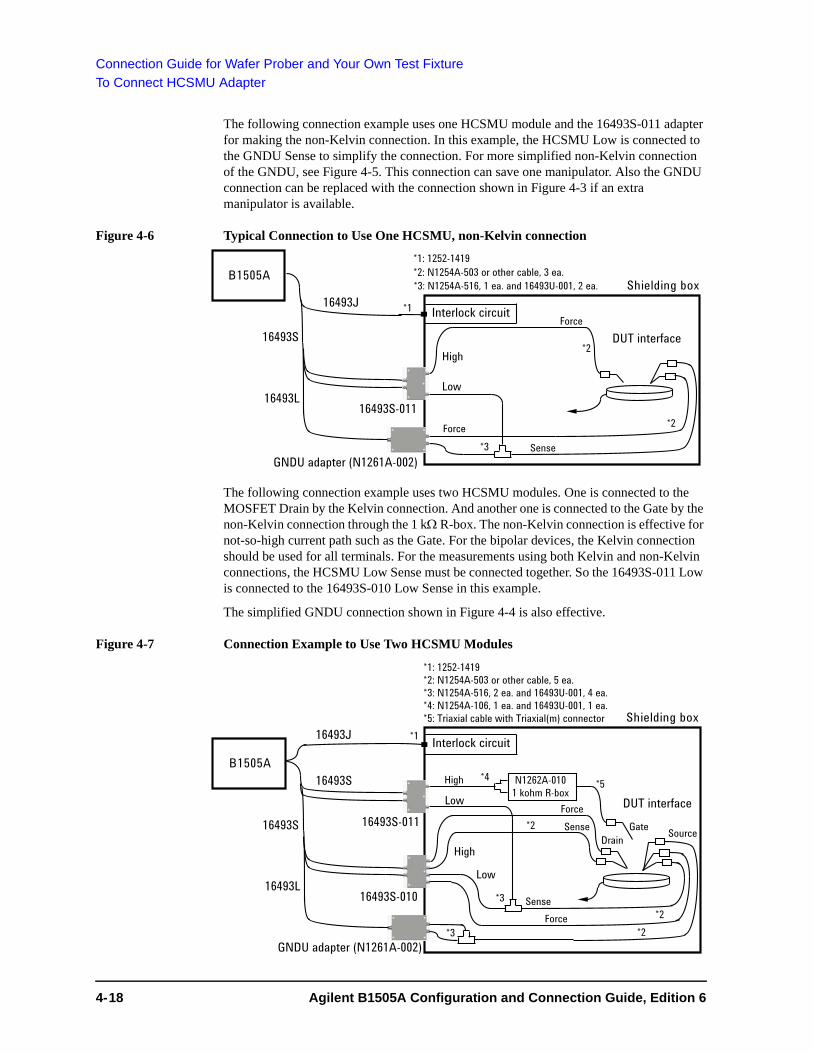
Connection Guide for Wafer Prober and Your Own Test Fixture
To Connect HCSMU Adapter
The following connection example uses one HCSMU module and the 16493S-011 adapter for making the non-Kelvin connection. In this example, the HCSMU Low is connected to the GNDU Sense to simplify the connection. For more simplified non-Kelvin connection of the GNDU, see Figure 4-5. This connection can save one manipulator. Also the GNDU connection can be replaced with the connection shown in Figure 4-3 if an extra manipulator is available.
Figure 4-6 Typical Connection to Use One HCSMU, non-Kelvin connection
The following connection example uses two HCSMU modules. One is connected to the MOSFET Drain by the Kelvin connection. And another one is connected to the Gate by the non-Kelvin connection through the 1 k R-box. The non-Kelvin connection is effective for not-so-high current path such as the Gate. For the bipolar devices, the Kelvin connection should be used for all terminals. For the measurements using both Kelvin and non-Kelvin connections, the HCSMU Low Sense must be connected together. So the 16493S-011 Low is connected to the 16493S-010 Low Sense in this example.
The simplified GNDU connection shown in Figure 4-4 is also effective.
Figure 4-7 Connection Example to Use Two HCSMU Modules
Shielding boxB1505A
DUT interface
16493S-011
Interlock circuit
16493L
*2: N1254A-503 or other cable, 3 ea.
Force
Low
High
Force
*3: N1254A-516, 1 ea. and 16493U-001, 2 ea.
*1: 1252-1419
*2
*1
*2
SenseGNDU adapter (N1261A-002)
*3
16493J
16493S
Shielding box
B1505A
DUT interface
16493S-010
16493S
16493L
Interlock circuit
SenseForce
Low
High
SenseForce
*2
*1
*2
*1: 1252-1419*2: N1254A-503 or other cable, 5 ea.*3: N1254A-516, 2 ea. and 16493U-001, 4 ea.*4: N1254A-106, 1 ea. and 16493U-001, 1 ea.*5: Triaxial cable with Triaxial(m) connector
*3*2
16493S-011
High
Low
*3
*5*4 N1262A-0101 kohm R-box
GateDrain Source
GNDU adapter (N1261A-002)
16493S
16493J
4- 18 Agilent B1505A Configuration and Connection Guide, Edition 6

Connection Guide for Wafer Prober and Your Own Test Fixture
To Connect Dual HCSMU Adapter
To Connect Dual HCSMU AdapterAgilent 16493S-020/021 Dual HCSMU adapter is used to configure the DHCSMU channel by connecting two HCSMU modules installed in one B1505A. Using two modules can expand the B1505A maximum current up to ± 40 A (pulse), ± 2 A (DC).
16493S-020: Dual HCSMU Kelvin combination adapter, for connecting a DUT interface such as your own test fixture and wafer prober, not the N1259A test fixture
16493S-021: Dual HCSMU combination adapter, for connecting the N1259A/N1265A test fixture, the N1258A module selector, or the 16493S-010/011 HCSMU adapter
NOTE Do not connect or put any conductor on the HCSMU Low Force and Low Sense terminals, outer conductor of the coaxial connectors. Connecting or putting conductor of circuit common, chassis ground, or any potential on causes the measurement error.
To Connect 16493S-020
The 16493S-020 adapter is used to connect a DUT interface such as your own test fixture and wafer prober. This adapter cannot be used with the N1258A module selector.
The adapter should be installed near your DUT interface and connected between the B1505A and your DUT interface as shown in Figure 4-8. This adapter has built-in GNDU protection adapter and built-in HCSMU Kelvin adapter. So the 16493S-010/011 and N1261A-002/004 adapters are not required.
Figure 4-8 Typical Connection of Dual HCSMU Kelvin Combination Adapter
Shielding boxB1505A
DUT interface
16493S-020
Interlock circuit
16493S, 2 ea.
16493L
Sense
ForceLow
High Sense
Force*2*1
*4
*1: 1252-1419*2: N1254A-506 or other cable, 1 ea.*3: N1254A-505 or other cable, 1 ea.*4: N1254A-503 or other cable, 2 ea.
*3
16493J
LowHigh
Agilent B1505A Configuration and Connection Guide, Edition 6 4- 19

Connection Guide for Wafer Prober and Your Own Test Fixture
To Connect Dual HCSMU Adapter
Table 4-12 To Connect 16493S-020 Input
Table 4-13 To Connect 16493S-020 Output
B1505A terminals Required cables Input terminals
HCSMU used for master
Force 16493S HCSMU cable, 3 m or 1.5 m HCSMU Master
Force
Sense Sense
HCSMU used for
slave
Force 16493S HCSMU cable, 3 m or 1.5 m HCSMU Slave
Force
Sense Sense
GNDU 16493L GNDU cable, 3 m or 1.5 m GNDU
Output terminals1
1. This is the DHCSMU channel. The connectors are compatible with the N1258A module selector output connectors.
Required cables/Description Connect to
Low Force Coaxial cable with BNC(m) connector. N1254A-503 can be used. DUT low terminal
(ex: source)2
2. Non-Kelvin connection is not allowed. GNDU Force and Sense are internally connected to Low Sense.
Sense Coaxial cable with BNC(m) connector. N1254A-503 can be used.
High Force Coaxial cable with HV(plug) connector. N1254A-506 can be used. Use coaxial cable to minimize affect of inductance.
DUT high terminal
(ex: drain)2
Sense Triaxial cable with HV(plug) connector. N1254A-505 can be used.
Forc
eSe
nse
Forc
eSe
nse
Sens
e/Fo
rce
Circ
uit
Com
mon
Se
nse/
Forc
e Ci
rcui
t Co
mm
on H
igh
Low
(±40
V
Max
)O
utpu
t
1649
3S O
pt 0
20
Dua
l HC
SMU
Kel
vin
Com
bina
tion
Ada
pter
ForceSense
ForceSense
Master
Slave
HCSM
UG
ND
UInput
4- 20 Agilent B1505A Configuration and Connection Guide, Edition 6

Connection Guide for Wafer Prober and Your Own Test Fixture
To Connect Dual HCSMU Adapter
To Connect 16493S-021
The 16493S-021 adapter is used with an accessory, 16493S-010/011 HCSMU adapter, N1258A module selector, or N1259A/N1265A test fixture. The adapter should be installed near the accessory.
Table 4-14 To Connect 16493S-021 Input
Table 4-15 To Connect 16493S-021 Output
CAUTION If DHCSMU is used with the N1258A or N1259A-300 module selector, the maximum current must be ± 30 A to prevent the module selector from performance degradation and failure.
B1505A terminals Required cables Input terminals
HCSMU used for master
Force 16493S HCSMU cable, 3 m or 1.5 m Master Force
Sense Sense
HCSMU used for
slave
Force 16493S HCSMU cable, 3 m or 1.5 m Slave Force
Sense Sense
Output terminals1
1. This is the DHCSMU channel. The connectors are compatible with HCSMU.
Required cables/Description Connect to
Output Force dedicated cable, 300 mm, furnished with 16493S-021
To connect N1265A, adapters N1254A-103 for Force and N1254A-517 for Sense are required.
HCSMU input connectors of
16493S-010/011, N1258A, N1259A,
or N1265A
Sense
1649
3S O
pt 0
21
Dua
l HC
SMU
Com
bina
tion
Ada
pter
Forc
eSe
nse
High
Se
nse
Low
Se
nse
HCSM
U
Circ
uit
Com
mon
Hig
hFo
rce
Low
Forc
e
±40
V
Max
O
utpu
t
SenseForce
SenseForce
Master
Slave
From H
CSMU
Agilent B1505A Configuration and Connection Guide, Edition 6 4- 21

Connection Guide for Wafer Prober and Your Own Test Fixture
To Connect Protection Adapter
To Connect Protection AdapterAgilent N1261A protection adapter is used to protect GNDU or HP/MPSMU module from high voltage. The N1261A should be installed near your DUT interface as shown in Table 4-1 on page 4-5.
The N1261A-001 is also used for the measurement using the N1265A test fixture. It must be connected between the HP/MPSMU and the N1265A SMU input. Then use four 16494A triaxial cables for Kelvin connection or two 16494A cables for non-Kelvin connection. Recommended cable length is 1.5 m. Ignore Table 4-17.
N1261A-001: HPSMU protection adapter, Triaxial(f)-Triaxial(f)
N1261A-002: GNDU protection adapter, Triaxial(f)-BNC(f)
N1261A-003: HPSMU protection adapter, Triaxial(f)-HV(jack)
N1261A-004: GNDU protection adapter, Triaxial(f)-SHV(jack)
Table 4-16 To Connect N1261A Input
NOTE For connecting HP/MPSMU, use either 16494A or 16493K. But the 16493K cannot be used for connecting the N1265A.
B1505A terminals Required cables N1261A terminals
HPSMU or
MPSMU
Force 16494A Triaxial cable, 3 m or 1.5 m, 1 ea., for the non-Kelvin connection, connect it between the Force connectors.
For the Kelvin connection, prepare additional one more cable and connect it between the Sense connectors. Or use 16493K Kelvin triaxial cable instead of 16494A.
From HPSMU
Force
Sense Sense
GNDU 16493L GNDU cable, 3 m or 1.5 m From GNDU
N 1261A O pt 001H P S M U P rotec tion A dapter
Force
S ense
F romH P S M U O utput
Guard
S ense/Force
C ircu itC om m on
!
Force200V m a x
S ense200V m a x
A g ilent
Inp utPeak 3kV=m ax
N 1261A O pt 001H P S M U P rotec tion A dapter
Force
S ense
F romH P S M U O utput
Guard
S ense/Force
C ircu itC om m on
!
Guard
S ense/Force
C ircu itC om m on
!!
Force200V m a x
Force200V m a x200V m a x
S ense200V m a x
S ense200V m a x200V m a x
A g ilent
Inp utPeak 3kV=m ax
N 1261A O pt 002G N D U P rotec tion A dapter
F rom G N D U O utput
Force
S ense
A g ilent
Force
S ense
C ircu itC om m on
S ense/Force
C ircu itC om m on
40 V m axInp utPeak 3kV=m a x
N 1261A O pt 002G N D U P rotec tion A dapter
F rom G N D U O utput
Force
S ense
A g ilent
Force
S ense
C ircu itC om m on
Force
S ense
C ircu itC om m on
S ense/Force
C ircu itC om m on
S ense/Force
C ircu itC om m on
40 V m ax40 V m axInp utPeak 3kV=m a x
4- 22 Agilent B1505A Configuration and Connection Guide, Edition 6

Connection Guide for Wafer Prober and Your Own Test Fixture
To Connect Protection Adapter
Table 4-17 To Connect N1261A Output
Options Required cables/Description Connect to
N1261A-001 Force Triaxial cable with Triaxial(m) connector. DUT terminal (ex: gate)
or
Prober chuck
Sense Triaxial cable with Triaxial(m) connector.
N1261A-003 Force Triaxial cable with HV(plug) connector. N1254A-505 can be used. Also 16493T-001 and N1254A-500 can be used.
Sense Triaxial cable with HV(plug) connector. N1254A-505 can be used. Also 16493T-001 and N1254A-500 can be used.
N1261A-0021
1. For connecting HCSMU adapter, see “To Connect HCSMU Adapter” on page 4-16.
Force Coaxial cable with BNC(m) connector. N1254A-503 can be used. DUT terminal (ex: source)
Non-Kelvin connection is not allowed.
Sense Coaxial cable with BNC(m) connector. N1254A-503 can be used.
N1261A-004 Force Coaxial cable with SHV(plug) connector.
Sense Coaxial cable with SHV(plug) connector.
N 1261A O pt 001H P S M U P rotec tion A dapter
Force
S ense
F romH P S M U O utput
Guard
S ense/Force
C ircu itC om m on
!
Force200V m a x
S ense200V m a x
A g ilent
Inp utPeak 3kV=m ax
N 1261A O pt 001H P S M U P rotec tion A dapter
Force
S ense
F romH P S M U O utput
Guard
S ense/Force
C ircu itC om m on
!
Guard
S ense/Force
C ircu itC om m on
!!
Force200V m a x
Force200V m a x200V m a x
S ense200V m a x
S ense200V m a x200V m a x
A g ilent
Inp utPeak 3kV=m ax
N 1261A O pt 002G N D U P rotec tion A dapter
F rom G N D U O utput
Force
S ense
A g ilent
Force
S ense
C ircu itC om m on
S ense/Force
C ircu itC om m on
40 V m axInp utPeak 3kV=m a x
N 1261A O pt 002G N D U P rotec tion A dapter
F rom G N D U O utput
Force
S ense
A g ilent
Force
S ense
C ircu itC om m on
Force
S ense
C ircu itC om m on
S ense/Force
C ircu itC om m on
S ense/Force
C ircu itC om m on
40 V m ax40 V m axInp utPeak 3kV=m a x
Agilent B1505A Configuration and Connection Guide, Edition 6 4- 23

Connection Guide for Wafer Prober and Your Own Test Fixture
To Connect High Voltage Bias Tee
To Connect High Voltage Bias TeeAgilent N1260A high voltage bias-tee is used to perform the high voltage C-V measurement. The C-V measurement of up to 3000 Vdc can be realized by using the bias-tee, MFCMU, and HVSMU. The N1260A should be installed near your DUT interface as shown in Table 4-1 on page 4-5. Also see Figure 4-9 for connection example.
The N1260A is also used for the high voltage C-V measurement using the N1265A test fixture. It must be connected between the MFCMU and the N1265A. Then use two N1254A-518 SHV cables to connect the N1260A output to the N1265A Bias Tee input. The N1260A input connection is same as Table 4-18. Ignore Table 4-19.
Table 4-18 To Connect N1260A Input
NOTE Turn the B1505A off before connecting the CMU cable.
Connect HVSMU to obtain DC bias input. Because the bias-tee cannot pass the MFCMU internal DC bias.
B1505A terminals Required cables N1260A terminals
HVSMU Force 16493T HVSMU cable, 3 m or 1.5 m From HVSMU
MFCMU Hcur N1300A CMU cable, 3 m or 1.5 m
It is not needed to connect the ground wire extended from the CMU cable.
From MFCMU
Hcur
Hpot Hpot
Lpot Lpot
Lcur Lcur
From HVSMU
Hcur Hpot Lpot Lcur
From MFCMU
3kV M ax3kV M ax
!!
4- 24 Agilent B1505A Configuration and Connection Guide, Edition 6

Connection Guide for Wafer Prober and Your Own Test Fixture
To Connect High Voltage Bias Tee
Table 4-19 To Connect N1260A Output
Figure 4-9 To Connect N1260A High Voltage Bias-Tee
N1260A terminals Required cables/Description Connect to
Output Low Coaxial cable with SHV(plug) connector. DUT low terminal (ex: source)
High Coaxial cable with SHV(plug) connector. DUT high terminal (ex: drain)
AC Guard Coaxial cable with SHV(plug) connector.
This terminal provides the AC guard (circuit common) signal of MFCMU. For the 3-terminal device measurement, the AC Guard must be extended to the device terminal which is not connected to Low or High.
DUT terminal (ex: gate)
AC Guard HighLow
Signal
AC Guard/Return
!!!
Output
3kV M ax
AC Guard HighLow
Signal
AC Guard/Return
!!!
Output
3kV M ax3kV M ax
B1505A
Hcur
MFCMU
N1260A High Voltage Bias-T
HVSMU
Force
N1300A
Hpot
Lpot
Lcur
HVSMU 16493T
High
Low DUT
AC Guard
Agilent B1505A Configuration and Connection Guide, Edition 6 4- 25

Connection Guide for Wafer Prober and Your Own Test Fixture
To Connect Module Selector
To Connect Module SelectorAgilent N1258A module selector is used to switch the measurement resource connected to the device under test (DUT) automatically. The measurement resource will be HP/MPSMU, HVSMU/HVMCU, or HC/DHCSMU. One selector provides one switching channel. Also the selector has built-in GNDU protection adapter, built-in HPSMU protection adapter, and built-in HCSMU Kelvin adapter.
The N1258A should be installed near your DUT interface as shown in Table 4-3 on page 4-7. Also see figures 4-11 and 4-12.
The output cable connection is effective for all measurement performed by the modules connected to the Input terminals. Connection change is not required. The module selector switching status is indicated by the Status indicator mounted on the front panel. See Table 4-22 on page 4-30.
Figure 4-10 Module Selector Circuit Diagram and Connections
CAUTION The GNDU can sink current of up to 4.2 A. Use 16493L GNDU cable to connect the GNDU to the N1258A.
Do not use normal triaxial cable (16494A) because the maximum current rating of the cable is 1 A.
CAUTION Maximum current must be ± 30 A to prevent the module selector from performance degradation and failure.
NOTE Using Dual HCSMU (DHCSMU)
DHCSMU can be configured by two HCSMU modules installed in one B1505A and connected to the 16493S-021 Dual HCSMU combination adapter. See “To Connect Dual HCSMU Adapter” for connection. The output connectors are compatible with HCSMU.
Front view
DUT high terminal
DUT highHPSMU
DUT low
Module Selector
Open
High
HVSMUHCSMU
GNDU
Low AC power
B1505A Digital I/OHCSMU Force+SenseHPSMU Force+SenseGNDU Force+SenseHVSMU Force
Rear view
DUT low terminal
Open
100 kW
4- 26 Agilent B1505A Configuration and Connection Guide, Edition 6

Connection Guide for Wafer Prober and Your Own Test Fixture
To Connect Module Selector
Figure 4-11 To Connect N1258A Module Selector
Figure 4-12 To Connect N1258A Module Selector, with N1261A-002 GNDU Adapter
NOTE Using GNDU Adapter
Generally, the connection of Figure 4-11 is used for the measurement using the module selector. And the connection of Figure 4-12 is effective for the accurate measurement over 10 mA using the HP/MPSMU or HVSMU.
CAUTION Never connect the HVSMU Force and Guard terminals and the HVMCU High terminal to any output, including circuit common, chassis ground, or any other measurement resource such as SMU. Connecting other measurement resource may damage the connected one.
NOTE Do not connect or put any conductor on the HCSMU Low Force and Low Sense terminals, outer conductor of the coaxial connectors. Connecting or putting conductor of circuit common, chassis ground, or any potential on causes the measurement error.
HCSMU Force
N1258A Module Selector
HVSMU Force
16493L
HCSMU Sense
HPSMU Force
HPSMU Sense
16493T
High Force
DUT
GNDU
16493S
16493K 1 ea.or 16494A 2 ea.
High Sense
Low Force
Low Sense
B1505A
HCSMU
ForceHVSMU
GNDU
HPSMU
ForceSense
ForceSense
B1505A
HCSMU Force
HCSMU
N1258A Module Selector
HVSMU Force
Force
16493L
HCSMU Sense
HPSMU Force
HPSMU Sense
HVSMU16493T
High Force
DUT
GNDU
HPSMU GNDU
ForceSense
ForceSense
16493S
16493K 1 ea.or 16494A 2 ea.
High Sense
Low Force
Low Sense
Force
Sense
N1261A-002GNDUProtection Adapter*1 : N1254A-516, 1 ea. and 16493U-001, 2 ea.
*2 : N1254A-503, or a coaxial cable with BNC(m) connector
*1
*2
Agilent B1505A Configuration and Connection Guide, Edition 6 4- 27

Connection Guide for Wafer Prober and Your Own Test Fixture
To Connect Module Selector
Table 4-20 To Connect N1258A Input
WARNING The connector cap must be connected to the unused input connectors.
If the Circuit Common terminal is not connected to the frame ground terminal (for floating measurement), a potential shock hazard may present. Do not touch any of measurement circuit at any time while a floating measurement is in progress.
CAUTION For floating measurement, do not apply voltage more than ± 42 V to the Circuit Common terminal. Failure to heed this caution may result in damage to the N1258A.
B1505A terminals Required cables N1258A terminals
Digital I/O 16493G Digital I/O connection cable, 3 m or 1.5 m Digital I/O
HCSMU or
DHCSMU
Force 16493S HCSMU cable, 3 m or 1.5 m, 1 ea. for HCSMU
16493S HCSMU cable, 3 m or 1.5 m, 2 ea. and 16493S-021 Dual HCSMU adapter, 1 ea. for DHCSMU
HCSMU Force
Sense Sense
HPSMU or
MPSMU
Force 16494A Triaxial cable, 3 m or 1.5 m, 1 ea., for the non-Kelvin connection, connect it between the Force connectors.
For the Kelvin connection, prepare additional one more cable and connect it between the Sense connectors. Or use 16493K Kelvin triaxial cable instead of 16494A.
Use 16493K cable if the High output terminals are connected to the prober chuck.
HPSMU Force
Sense Sense
HVSMU Force 16493T HVSMU cable, 3 m or 1.5 m HVSMU
HVMCU1
1. HVMCU is configured by using the N1266A, HVSMU, GNDU, and two MCSMU. See “To Connect HVSMU Current Expander” on page 4-33.
High
Low 16493L GNDU cable, 3 m or 1.5 m GNDU
GNDU
Power cable, for connecting to power line LINE, 65 VA Max.
GNDU
HPSMU±200 V Max
HCSMU±40 V Max
Digital I/OSenseForce SenseForce
N10149
HVSMU
LINE100–240 V50/60 Hz65 VA Max
CircuitCommon
For floating measurements disconnect shorting bar. Do not apply more than ±42 V to Circuit Common.
Input
±3 kV Max
4- 28 Agilent B1505A Configuration and Connection Guide, Edition 6
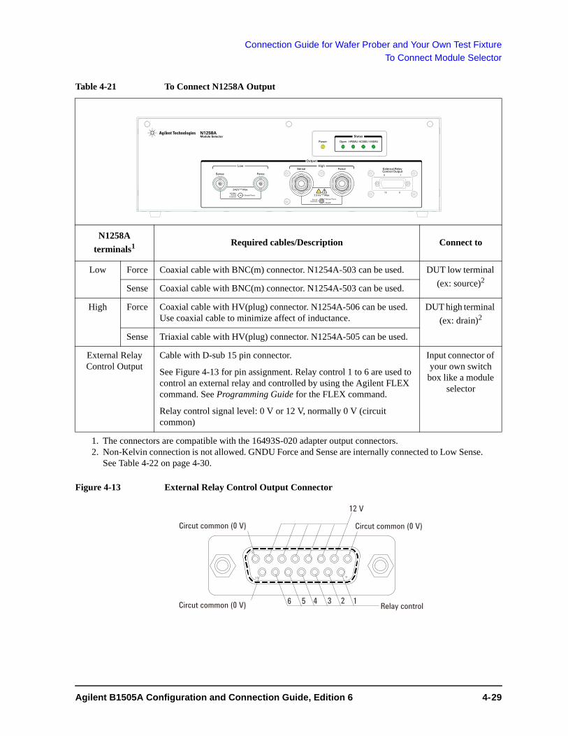
Connection Guide for Wafer Prober and Your Own Test Fixture
To Connect Module Selector
Table 4-21 To Connect N1258A Output
Figure 4-13 External Relay Control Output Connector
N1258A
terminals1
1. The connectors are compatible with the 16493S-020 adapter output connectors.
Required cables/Description Connect to
Low Force Coaxial cable with BNC(m) connector. N1254A-503 can be used. DUT low terminal
(ex: source)2
2. Non-Kelvin connection is not allowed. GNDU Force and Sense are internally connected to Low Sense. See Table 4-22 on page 4-30.
Sense Coaxial cable with BNC(m) connector. N1254A-503 can be used.
High Force Coaxial cable with HV(plug) connector. N1254A-506 can be used. Use coaxial cable to minimize affect of inductance.
DUT high terminal
(ex: drain)2
Sense Triaxial cable with HV(plug) connector. N1254A-505 can be used.
External Relay Control Output
Cable with D-sub 15 pin connector.
See Figure 4-13 for pin assignment. Relay control 1 to 6 are used to control an external relay and controlled by using the Agilent FLEX command. See Programming Guide for the FLEX command.
Relay control signal level: 0 V or 12 V, normally 0 V (circuit common)
Input connector of your own switch
box like a module selector
N1258AModule Selector
Force External Relay Control Output
Sense
ForceSense
Output
±3 kV Max Sense/Force
Guard Circuit
Common
Power HPSMU Open HCSMU HVSMU
Status
8 1
15 9Sense/Force
±42V Max
HighLow
HCSMUCircuit
Common
12 V
Circut common (0 V)Circut common (0 V)
Circut common (0 V) Relay control16 5 4 3 2
Agilent B1505A Configuration and Connection Guide, Edition 6 4- 29

Connection Guide for Wafer Prober and Your Own Test Fixture
To Connect Module Selector
NOTE Controlling N1258A input-to-output path
The configuration and the default I/O path of the N1258A are set by using the Module Selector tab screen of the Configuration window of the EasyEXPERT software. The connection path from the input port to the output port is controlled by each test setup. And the N1258A switching status is indicated by the Status indicator mounted on the front panel. See Figure 4-14 and Table 4-22 for the indication and the connection path.
Figure 4-14 Module Selector Simplified Internal Connections
Table 4-22 Module Selector Status Indicator and Input-to-Output Connection Path
Measurement resource used for the test
Status indicator
Input-to-output connection1 of output terminals
1. In the normal state, the N1258A makes the path to the output port from the input port specified by the Default field. When a measurement is performed, the N1258A performs automatic switching in every test. The N1258A makes the path to the output port from the measurement resource used for the test.
Low Sense Low Force High Sense High Force
2
2. This condition is when all Input fields HVSMU, HCSMU, and HPSMU are blank.
Open HCSMU Low Sense
+ GNDU Force+ GNDU Sense
HCSMU Low Force
Open Open
HPSMU or MPSMU HPSMU HPSMU Sense
HPSMU Force
HCSMU or DHCSMU HCSMU HCSMU High Sense
HCSMU High Force
HVSMU or HVMCU HVSMU HVSMU Force Open
HVSMU/HVMCU and built-in series resistor
HVSMU Force
+ Series resistor
Low HighS F
S: Sense
F: Force
P.AP.A
GNDU HCSMU HPSMU HVSMUS FS F
SF
F
P.A:Protection adapter
S F
GNDU force and senseare connected to Lowsense line.HVSMU force is connected to High sense line.
100 kW
4- 30 Agilent B1505A Configuration and Connection Guide, Edition 6

Connection Guide for Wafer Prober and Your Own Test Fixture
To Connect HVSMU/HCSMU Fast Switch
To Connect HVSMU/HCSMU Fast SwitchAgilent N1267A HVSMU/HCSMU fast switch is used to switch quickly and automatically the measurement resource, HVSMU or HCSMU, connected to the device under test (DUT). This is effective for the current collapse measurement of GaN power devices.
The N1267A can be used with the N1259A test fixture, but not with the N1265A test fixture. See Table 2-3 for the input output cable connections.
If you use your DUT interface, see Table 4-4 and Figure 4-15 for the connection image.
The output cable connection is effective for all measurement performed by the measurement resources connected to the Input terminals. Connection change is not required. See Figure 4-16 for the internal connection.
Figure 4-15 To Connect HVSMU/HCSMU Fast Switch
Figure 4-16 N1267A Simplified Internal Connections
HCSMU Force
N1267A Fast Switch
HVSMU Force
16493L
HCSMU Sense
MCSMU Force
MCSMU Sense
16493T
High Force
DUT
GNDU
16493S
16494A 2 ea.
Low Force
B1505A
HCSMU
ForceHVSMU
GNDU
MCSMU
ForceSense
ForceSense
Low HighF
F: Force
P.A
GNDU HCSMU HVSMUS F
SF
F
P.A:Protection adapter
F
When the HCSMU is used, N1267A steps down the High output voltage to the HCSMU high output voltage.
MCSMUS, F
SW control
S: Sense
Agilent B1505A Configuration and Connection Guide, Edition 6 4- 31

Connection Guide for Wafer Prober and Your Own Test Fixture
To Connect HVSMU/HCSMU Fast Switch
Table 4-23 To Connect N1267A Input
Table 4-24 To Connect N1267A Output
CAUTION The GNDU can sink current of up to 4.2 A. Use 16493L GNDU cable to connect the GNDU to the N1267A.
Do not use normal triaxial cable (16494A) because the maximum current rating of the cable is 1 A.
CAUTION Never connect the HVSMU Force and Guard terminals to any output, including circuit common, chassis ground, or any other measurement resource such as SMU. Connecting other measurement resource may damage the connected one.
NOTE Do not connect or put any conductor on the HCSMU Low Force and Low Sense terminals, outer conductor of the coaxial connectors. Connecting or putting conductor of circuit common, chassis ground, or any potential on causes the measurement error.
B1505A terminals Required cables N1267A terminals
HCSMU Force 16493S HCSMU cable, 3 m or 1.5 m, 1 ea. HCSMU Force
Sense Sense
HVSMU Force 16493T HVSMU cable, 3 m or 1.5 m HVSMU
GNDU 16493L GNDU cable, 3 m or 1.5 m GNDU
MCSMU Force 16494A Triaxial cable, 3 m or 1.5 m MCSMU Force
Sense 16494A Triaxial cable, 3 m or 1.5 m Sense
N1267A terminals
Required cables/Description Connect to
Low Force Coaxial cable with BNC(m) connector. N1254A-503 can be used. DUT low terminal (ex: source)
High Force Coaxial cable with HV(plug) connector. N1254A-506 can be used. Use coaxial cable to minimize affect of inductance.
DUT high terminal (ex: drain)
4- 32 Agilent B1505A Configuration and Connection Guide, Edition 6

Connection Guide for Wafer Prober and Your Own Test Fixture
To Connect HVSMU Current Expander
To Connect HVSMU Current ExpanderThe N1266A HVSMU current expander is used to configure the high voltage medium current unit (HVMCU) by using the HVSMU module and the MCSMU modules as shown in Figure 4-17. The N1266A should be installed near the B1505A.
The N1266A output can be selected from the HVSMU or HVMCU. The switching status is indicated by the Status indicator mounted on the front panel. See Table 4-25 for the internal connection.
NOTE To switch measurement resource
The configuration of the HVMCU is set by using the HVSMU Current Expander tab screen of the Configuration window of the EasyEXPERT software. The measurement resource HVMCU or HVSMU is controlled by each test setup. And the switching status is indicated by the Status indicator mounted on the front panel. See Table 4-25 for the indication and the connection path.
Figure 4-17 To Configure HVMCU
Table 4-25 N1266A Status Indicator and Input-to-Output Connection Path
Measurement resource used for the test
Status indicator
Input-to-output connection1 of output terminals
1. When a measurement is performed, the N1266A performs automatic switching in every test. The N1266A makes the path to the output port from the measure-ment resource used for the test.
Low High
GNDU only (off) GNDU Force + Sense
Open
HVMCU HVMC HVMCU High
HVSMU HVSMU HVSMU Force
HVSMU and built-in series resistor
HVSMU Force + Series resistor
N1266A HVSMU current expander
HVSMU
GNDU
V-controlI-control
Digital I/O Digital I/O
MC/HCSMUMC/HCSMU
B1505A
HVSMU
GNDULow
DUT Drain
Source
HighHVMCU
*1: N1261A-002/004 protection adapter is required for connecting prober.
N1261A-002or 004(*1)
Open
Agilent B1505A Configuration and Connection Guide, Edition 6 4- 33
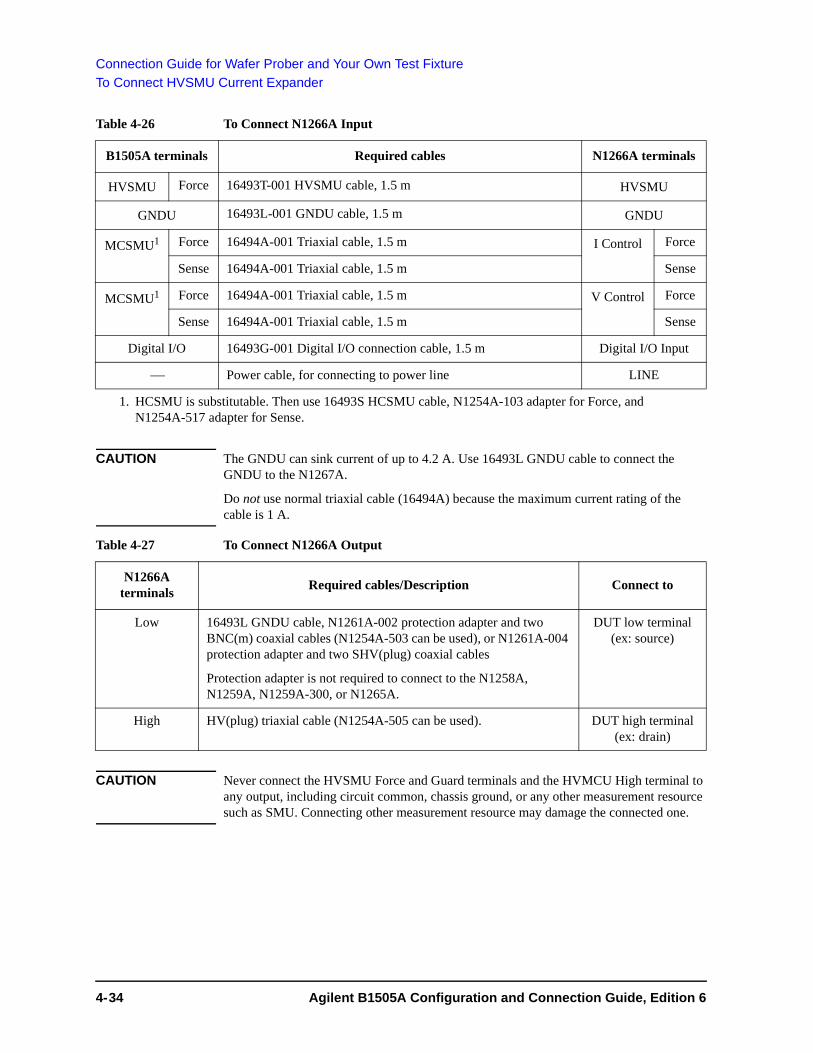
Connection Guide for Wafer Prober and Your Own Test Fixture
To Connect HVSMU Current Expander
Table 4-26 To Connect N1266A Input
CAUTION The GNDU can sink current of up to 4.2 A. Use 16493L GNDU cable to connect the GNDU to the N1267A.
Do not use normal triaxial cable (16494A) because the maximum current rating of the cable is 1 A.
Table 4-27 To Connect N1266A Output
CAUTION Never connect the HVSMU Force and Guard terminals and the HVMCU High terminal to any output, including circuit common, chassis ground, or any other measurement resource such as SMU. Connecting other measurement resource may damage the connected one.
B1505A terminals Required cables N1266A terminals
HVSMU Force 16493T-001 HVSMU cable, 1.5 m HVSMU
GNDU 16493L-001 GNDU cable, 1.5 m GNDU
MCSMU1
1. HCSMU is substitutable. Then use 16493S HCSMU cable, N1254A-103 adapter for Force, and N1254A-517 adapter for Sense.
Force 16494A-001 Triaxial cable, 1.5 m I Control Force
Sense 16494A-001 Triaxial cable, 1.5 m Sense
MCSMU1 Force 16494A-001 Triaxial cable, 1.5 m V Control Force
Sense 16494A-001 Triaxial cable, 1.5 m Sense
Digital I/O 16493G-001 Digital I/O connection cable, 1.5 m Digital I/O Input
Power cable, for connecting to power line LINE
N1266A terminals
Required cables/Description Connect to
Low 16493L GNDU cable, N1261A-002 protection adapter and two BNC(m) coaxial cables (N1254A-503 can be used), or N1261A-004 protection adapter and two SHV(plug) coaxial cables
Protection adapter is not required to connect to the N1258A, N1259A, N1259A-300, or N1265A.
DUT low terminal (ex: source)
High HV(plug) triaxial cable (N1254A-505 can be used). DUT high terminal (ex: drain)
4- 34 Agilent B1505A Configuration and Connection Guide, Edition 6

Connection Guide for Wafer Prober and Your Own Test Fixture
To Connect Ultra High Current Expander
To Connect Ultra High Current ExpanderThe ultra high current expander is built into the N1265A test fixture, and is used to configure the ultra high current unit (UHCU) with the MCSMU modules. The UHCU output can be applied from the Selector Output terminals of the N1265A, and extended by using the N1254A-524 Prober System Cable, 1.8 m. See “Selector Output Terminals” on page 3-13 for the selector itself and the output terminals.
The N1254A-524 system cable is used to extend the Selector Output and Gate terminals of the N1265A, and can be connected to these terminals directly. See “Connecting System Cable to N1265A” on page 4-36.
The other side, prober side, of the system cable is a connector box which provides the five connectors for connecting cables from manipulators. The connector box should be installed near your DUT interface. See Figure 4-18 for the connection image.
The prober side connector type, maximum voltage, and maximum current of the N1254A-524 are shown in Table 4-28. See Table 4-29 for the output connection cables.
CAUTION Do not apply voltage/current over the maximum limit of the cable. See Table 4-28.
Figure 4-18 To Extend Selector Output by using N1254A-524 Prober System Cable
Table 4-28 Prober Side Connectors and Maximum Voltage/Current of N1254A-524
Connector label
Connector type
N1265A output terminals to extend
Maximum voltage
Maximum current
High Force Banana(jack) Selector Output High Force 3000 V 39 A dc
Low Force Banana(jack) Selector Output Low Force 200 V
High Sense HV(jack) Selector Output High Sense 3000 V 1 A dc, 20 A pulse
Low Sense BNC(f) Selector Output Low Sense 200 V
Gate Low
Gate BNC(f) Gate High 200 V
N1254A-524 Prober System Cable
High Force
Guard
N1265A Test Fixture
Gate
Drain
Source
Selec
tor O
utpu
t
Chassis
Low Force
High SenseLow Sense
Gate HighGate Low High Force
Low Force
High Sense
Low Sense
Gate
Gate
DUT
Agilent B1505A Configuration and Connection Guide, Edition 6 4- 35

Connection Guide for Wafer Prober and Your Own Test Fixture
To Connect Ultra High Current Expander
Table 4-29 Cables for connecting Prober Side of N1254A-524 System Cable
CAUTION Never connect the High Force and High Sense terminals to any output, including circuit common, chassis ground, or any other measurement resource such as SMU. Connecting other measurement resource may damage the connected one.
CAUTION Do not grab the fixture cover when lifting the N1265A.
Connecting System Cable to N1265A
Requirements • Box wrench, M5 hex
• Clear plastic plate, 2 ea. (furnished with the N1254A-524 system cable)
Procedure 1. Turn the all instruments off.
2. Remove power cable from the all instruments.
3. Open the fixture cover of the N1265A.
4. Remove connection wire from the Selector Output and Gate terminals if the wire is connected.
5. Remove the clear plastic plate from the fixture cover. This makes opening for the N1254A-524 system cable.
Use the box wrench and unscrew six hex nuts to remove the plate.
6. Pass two connection boxes of the system cable through the opening.
7. Connect the connection boxes to the Selector Output and Gate terminals properly.
8. Set and fix two clear plastic plates instead of the original clear plastic plate to the fixture cover by using the hex nuts removed in the step 5. The plates close the excess opening, and make the opening requred for the cable only.
9. Close the fixture cover of the N1265A.
10. Connect the 16493J interlock cable from the B1505A or the N1268A to the interlock circuit installed in the shielding box of the prober station.
N1254A-524 connectors
Required cables/Description Connect to
Low Force Ultra high current cable with banana(plug). N1254A-523 can be used.
DUT low terminal (ex: source)
Low Sense Coaxial cable with BNC(m) connector. N1254A-503 can be used.
High Force Ultra high current cable with banana(plug). N1254A-523 can be used.
DUT high terminal (ex: drain)
High Sense Triaxial cable with HV(plug) connector. N1254A-505 can be used. Use coaxial cable to minimize affect of inductance.
Gate Coaxial cable with BNC(m) connector. N1254A-503 can be used. DUT drive terminal (ex: gate)
4- 36 Agilent B1505A Configuration and Connection Guide, Edition 6

Connection Guide for Wafer Prober and Your Own Test Fixture
To Connect Ultra High Voltage Expander
To Connect Ultra High Voltage ExpanderThe N1268A ultra high voltage expander is used to configure the ultra high voltage unit (UHVU) with the MCSMU modules. And the UHVU can be connected to prober as shown in Figure 4-19, by using the N1269A connection adapter. The N1268A should be installed near the B1505A. And the N1269A should be installed near prober as shown in “Connection Overview”.
Figure 4-19 To Configure UHVU
WARNING Connect a wire from an electrical ground (safety ground) to the earth terminal of the N1268A.
Table 4-30 To Connect N1268A/N1269A Input
B1505A terminals Required cables N1268A input
MCSMU Force 16494A-001 Triaxial cable, 1.5 m I Control Force
Sense 16494A-001 Triaxial cable, 1.5 m Sense
MCSMU1
1. HCSMU is substitutable. Then use 16493S HCSMU cable, N1254A-103 adapter for Force, and N1254A-517 adapter for Sense.
Force 16494A-001 Triaxial cable, 1.5 m V Control Force
Sense 16494A-001 Triaxial cable, 1.5 m Sense
Interlock 16493J-001 Interlock cable, 1.5 m Interlock Input
Digital I/O 16493G-001 Digital I/O connection cable, 1.5 m Digital I/O Input
Power cable, for connecting to power line LINE
Wire, 1 ea., for earthing (earth)
N1268A UHV expanderMCSMU
MC/HCSMU V-controlI-control
InterlockDigital I/O
Interlock InputDigital I/O
GateUHV Low
Chuck
Gate
ChuckSourceMCSMU
MCSMUN1269A UHV connection adapter
B1505A
LowDUT Drain
ChuckGate
Source
High
Interlock Output Interlock circuit
Agilent B1505A Configuration and Connection Guide, Edition 6 4- 37

Connection Guide for Wafer Prober and Your Own Test Fixture
To Connect Ultra High Voltage Expander
Table 4-31 To Connect N1268A/N1269A Output
CAUTION Never connect the High terminal to any output, including circuit common, chassis ground, or any other measurement resource such as SMU. Connecting other measurement resource may damage the connected one.
CAUTION Never connect the UHVU Low terminal to any other measurement resource except for the N1269A or N1265A-040 adapter. Connecting other measurement resource may damage the connected one.
B1505A/N1268A terminals
Required cables/Description N1269A input
MCSMU Force 16494A Triaxial cable, 1.5 m or 3 m Gate Force
Sense 16494A Triaxial cable, 1.5 m or 3 m Sense
MCSMU Force 16494A Triaxial cable, 1.5 m or 3 m Chuck Force
Sense 16494A Triaxial cable, 1.5 m or 3 m Sense
N1268A Output Low
SHV(jack)-SHV(jack) cable, 1.5 m or 3 m, of 16493V Low
N1268A output Required cables/Description Connect to
Interlock Output 16493J Interlock cable, 1.5 m or 3 m Interlock circuit
High Ultra high voltage coaxial cable with UHV(plug) connector. UHV cable of N1254A-520 can be used.
DUT high terminal (ex: drain)
N1269A output Required cables/Description Connect to
Gate Coaxial cable with SHV(plug) connector. SHV cable of N1254A-520 can be used.
DUT drive terminal (ex: gate)
Source Coaxial cable with SHV(plug) connector. SHV cable of N1254A-520 can be used.
DUT low terminal (ex: source)
Chuck Coaxial cable with SHV(plug) connector. SHV cable of N1254A-520 can be used.
DUT chuck terminal
4- 38 Agilent B1505A Configuration and Connection Guide, Edition 6

Connection Guide for Wafer Prober and Your Own Test Fixture
To Install an Interlock Circuit
To Install an Interlock Circuit The interlock circuit is designed to prevent electrical shock when a user touches the measurement terminals.
You must install an interlock circuit on a shielding box to prevent hazardous voltages when the door of the shielding box is open.
Figure 4-20 shows the pin assignments of the interlock connector that should be mounted on your DUT interface. And Table 4-32 lists the required parts to make the interlock circuit.
WARNING Potentially hazardous voltages may be present at the Force, Guard, and Sense terminals when the interlock terminals are shorted.
Figure 4-20 Interlock Connector Pin Assignments
Table 4-32 Recommended Parts
Agilent Part No. Description Quantity
N1254A-402 Interlock micro switch 2
1252-1419 Interlock connector (6 pin, female) 1
1450-0641 LED (VF 2.1 V @ IF = 10 mA) 1
Wire 24AWG, 600 V, 150 degree C or equivalent
1
2
34
5
6
Connector side
Interlock Switch
Wiring Side
LED
1
2
3 4
5
6
Agilent B1505A Configuration and Connection Guide, Edition 6 4- 39
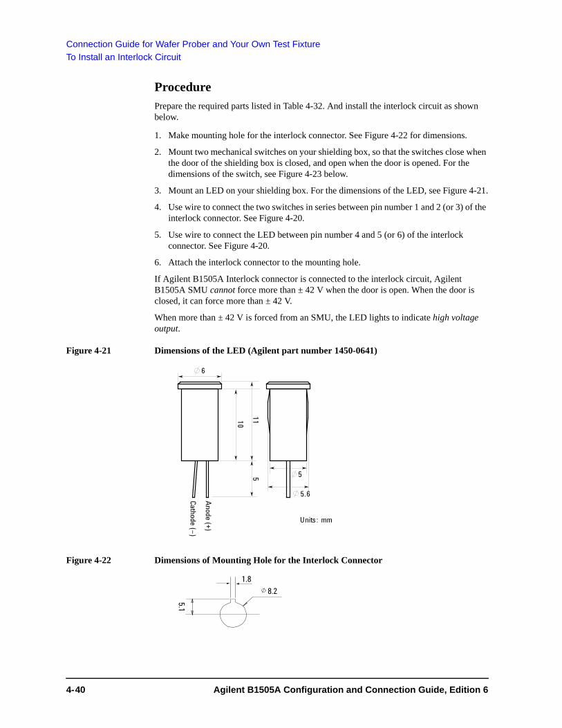
Connection Guide for Wafer Prober and Your Own Test Fixture
To Install an Interlock Circuit
Procedure
Prepare the required parts listed in Table 4-32. And install the interlock circuit as shown below.
1. Make mounting hole for the interlock connector. See Figure 4-22 for dimensions.
2. Mount two mechanical switches on your shielding box, so that the switches close when the door of the shielding box is closed, and open when the door is opened. For the dimensions of the switch, see Figure 4-23 below.
3. Mount an LED on your shielding box. For the dimensions of the LED, see Figure 4-21.
4. Use wire to connect the two switches in series between pin number 1 and 2 (or 3) of the interlock connector. See Figure 4-20.
5. Use wire to connect the LED between pin number 4 and 5 (or 6) of the interlock connector. See Figure 4-20.
6. Attach the interlock connector to the mounting hole.
If Agilent B1505A Interlock connector is connected to the interlock circuit, Agilent B1505A SMU cannot force more than ± 42 V when the door is open. When the door is closed, it can force more than ± 42 V.
When more than ± 42 V is forced from an SMU, the LED lights to indicate high voltage output.
Figure 4-21 Dimensions of the LED (Agilent part number 1450-0641)
Figure 4-22 Dimensions of Mounting Hole for the Interlock Connector
4- 40 Agilent B1505A Configuration and Connection Guide, Edition 6

Connection Guide for Wafer Prober and Your Own Test Fixture
To Install an Interlock Circuit
Figure 4-23 Dimensions of the Interlock Switch (Agilent N1254A-402)
To Connect Interlock Circuit
The B1505A provides the Interlock connector to prevent you from receiving an electrical shock from high voltage (more than ± 42 V). If the interlock circuit is open, the B1505A cannot apply high voltage more than ± 42 V.
Before performing measurement, connect the 16493J interlock cable between the B1505A Interlock connector and the interlock connector which is a part of the interlock circuit installed in your DUT interface as described in “Procedure” on page 4-40.
Agilent B1505A Configuration and Connection Guide, Edition 6 4- 41

Connection Guide for Wafer Prober and Your Own Test Fixture
About Cable Connections
About Cable ConnectionsPrepare the open end cable assemblies listed in Table 4-33 which contain the connector suitable for connecting the accessory, and connect it to your DUT interface.
• “To Make Connection to Reduce Leakage Current”
• “To Make Connection to Measure Low Resistance”
• “To Connect UHVU/HVSMU/HVMCU Output”
Table 4-33 Open End Cable Assemblies for Connecting Your DUT Interface
Cable assemblies Connect to Remarks
Coaxial cable with one BNC(m) N1258A Low Force/Sense N1254A-503
N1261A-002 Output Force/Sense
N1267A Low Force
N1254A-524 Low Sense and Gate
Triaxial cable with one HV(plug) N1261A-003 Output Force/Sense N1254A-505
N1258A High Sense
N1266A High
N1268A High Sense
N1254A-524 High Sense
Coaxial cable with one HV(plug) N1258A High Force N1254A-506
N1267A High Force
Triaxial cable with one Triaxial(m) N1261A-001 Output Force/Sense
N1262A-010/020 Output
Coaxial cable with one SHV(plug) N1260A Output Low/High/AC Guard N1254A-520
N1261A-004 Output Force/Sense
N1262A-001/002/011/021 Output
N1268A Low
N1269A Output Gate/Source/Chuck
Ultra high voltage cable with one UHV(plug) N1268A High N1254A-520
Ultra high current cable with one banana N1254A-524 High Force and Low Force N1254A-523
4- 42 Agilent B1505A Configuration and Connection Guide, Edition 6

Connection Guide for Wafer Prober and Your Own Test Fixture
About Cable Connections
To Make Connection to Reduce Leakage Current
To reduce the leakage current caused by connection cables, the guard technique is effective. Connect the probing needles to the coaxial cables as shown below:
1. Cut and trim end of the coaxial cable such as N1254A-503 and N1254A-506, so that the center conductor does not touch the outer conductor (connected to the guard terminal).
2. Connect the center conductor to tail of the probing needle. Never connect the outer conductor to the probing needle. However the outer conductor should be extended as close as possible to the probing needle.
3. Connect the outer conductor to the outer conductor of the probing needle if it is a coaxial probing needle.
Example The following example connection can be used to reduce the leakage current. Extend the outer conductor as close as possible to the probing needle. This also reduces the induced noise.
WARNING Do not touch the guard terminal with bare hands because you may be shocked by high voltage. The potential of the guard terminal is equal to the output voltage.
CAUTION Never connect the guard terminal to any other output, including circuit common, frame ground, or the terminals of any other unit.
Guarding Guarding reduces the leakage current between the measurement points and instrument. This is important when you measure low current.
The following figure shows the theory of guarding. The buffer amplifier (1) keeps the potential of the guard conductor at the same potential as the force conductor, so current does not flow between the force and guard conductors. Therefore, the current measured by SMU is same as current at measurement point because no current is leaked.
Probing needle
Contact pad
Outer conductorCenter conductor
Coaxial cable
Agilent B1505A Configuration and Connection Guide, Edition 6 4- 43

Connection Guide for Wafer Prober and Your Own Test Fixture
About Cable Connections
To Make Connection to Measure Low Resistance
When you measure a low resistance, high current flows through the DUT. This high current increases the measurement error caused by the residual resistance of cables. To cancel the effect of this resistance, you can use Kelvin connections (4-wire), which means the Force and Sense lines are extended separately to the DUT.
Connect the probing needles to the coaxial cables as shown below:
1. Cut and trim end of the coaxial cable such as N1254A-503 and N1254A-506, so that the center conductor does not touch the outer conductor (connected to the guard terminal).
2. Connect the center conductor to tail of the probing needle. Never connect the outer conductor to the probing needle. However the outer conductor should be extended as close as possible to the probing needle.
3. Connect the outer conductor to the outer conductor of the probing needle if it is a coaxial probing needle.
4. Perform 1 to 3 for both Force and Sense lines.
5. Contact the probing needles for the Force and Sense lines as close as possible to the DUT.
Example The following example connection can be used to measure low resistance. The Sense line is extended to the probing pad, and contacts the Force line through the pad, so the voltage drop due to the residual resistance caused by cables and wires is canceled.
Kelvin Connection Kelvin connections give good measurement results when you force high-current. The following figure shows the equivalent circuits for Kelvin and non-Kelvin connections.
Probing needleOuter conductorCenter conductor
Coaxial cable
Contact pad
Contact pad
4- 44 Agilent B1505A Configuration and Connection Guide, Edition 6

Connection Guide for Wafer Prober and Your Own Test Fixture
About Cable Connections
• For the non-Kelvin connection, the voltmeter measures the voltage drop of resistances rF1, RDUT, and rF2.
• For the Kelvin connection, the voltmeter measures the voltage drop of resistance RDUT only. The impedance of the voltmeter is very high, so the voltage drop of resistances rS1 and rS2 can be ignored.
The Kelvin connection is effective even when forcing voltage. The voltage drop due to the residual resistance of the Force line wiring is fed back to the voltage source via a comparator in the Sense line. The input impedance of comparator is high, and current flow into the Sense line is very low. So output error is not significant if the Sense line wiring has a residual resistance of 10 or less. Therefore, the specified voltage appears at the sense point (point where Sense line contacts Force line)
NOTE Kelvin connection and non-Kelvin connection
To make the Kelvin connection, use both Force and Sense terminals. Connecting the Force and Sense lines together at the terminal of the DUT (device under test) minimizes the measurement error caused by the residual resistance of the connection cables. The Kelvin connection is effective for the low resistance measurement and the high current measurement.
If you want to simplify the cable connections, open the Sense terminals and use the Force terminals only. This is the non-Kelvin connection. The Force terminals can be used to force and measure dc voltage or current.
To Connect UHVU/HVSMU/HVMCU Output
To prevent discharge and any accident, make enough space between the cable ends, also between the high side cable end and the shield or chassis. For example, make space of about 32 mm from the high side cable end for maximum 10 kV output. Also the creepage distance must be more than 100 mm for 10 kV.
Figure 4-24 Space around Cable End
To UHVU High To UHVU Low
DUT
Shield
Signal line
InsulatorSHV CableUHV Cable
Insulator
¡32 mm for 10 kV¡100 mm for 10 kV
Agilent B1505A Configuration and Connection Guide, Edition 6 4- 45

Connection Guide for Wafer Prober and Your Own Test Fixture
About Cable Connections
4- 46 Agilent B1505A Configuration and Connection Guide, Edition 6

5 Accessory Dimensions

Accessory Dimensions
This chapter describes the dimensions of accessories.
Dimensions and weight of accessories are listed in Table 5-1. Also you can find the dimensions of mounting hole and screw hole needed to fix the accessories in the following figures.
• “16493S-010 HCSMU Kelvin Adapter, in mm”
• “16493S-011 HCSMU non-Kelvin Adapter, in mm”
• “16493S-020 Dual HCSMU Kelvin Combination Adapter, in mm”
• “16493S-021 Dual HCSMU Combination Adapter, in mm”
• “N1254A-500/502 HV Connector for Soldering, mounting hole, in mm”
• “N1254A-501 HV jack - HV jack Adapter, mounting hole, in mm”
• “N1254A-521 UHV jack Adapter and SHV jack Adapter, mounting hole, in mm”
• “N1254A-524 Prober System Cable, Prober side, in mm”
• “N1258A Module Selector, in mm”
• “N1260A High Voltage Bias-T, in mm”
• “N1261A-001 HPSMU Protection Adapter, in mm”
• “N1261A-002 GNDU Protection Adapter, in mm”
• “N1261A-003 HPSMU Protection Adapter, HV Output, in mm”
• “N1261A-004 GNDU Protection Adapter, SHV Output, in mm”
• “N1262A-001/002/011/021 R-Box, HV-SHV, in mm”
• “N1262A-010/020 R-Box, Triaxial-Triax, in mm”
• “N1262A-023 R-Box, UHV-UHV, in mm”
• “N1267A HVSMU/HCSMU Fast Switch, in mm”
• “N1269A Ultra High Voltage Connection Adapter, in mm”
5- 2 Agilent B1505A Configuration and Connection Guide, Edition 6

Accessory Dimensions
Table 5-1 Dimensions and Weight of Accessories
Model/Option Description Dimensions1 in mm
1. Body size. Excluding connectors.
Weight in kg
16493S-010 HCSMU Kelvin adapter 104 (W) 38 (H) 60 (D) 0.3
16493S-011 HCSMU non-Kelvin adapter 104 (W) 38 (H) 60 (D) 0.3
16493S-020 Dual HCSMU Kelvin combination adapter 164 (W) 50 (H) 125 (D) 0.3
16493S-021 Dual HCSMU combination adapter 104 (W) 53 (H) 60 (D) 0.3
N1258A Module selector 330 (W) 102 (H) 372 (D) 5.0
N1260A High voltage bias-T 164 (W) 50 (H) 125 (D) 0.6
N1261A-001 HPSMU protection adapter, Triaxial(f) 80 (W) 40 (H) 120 (D) 0.3
N1261A-002 GNDU protection adapter, BNC(f) 80 (W) 40 (H) 120 (D) 0.3
N1261A-003 HPSMU protection adapter, HV(jack) 80 (W) 40 (H) 150 (D) 0.3
N1261A-004 GNDU protection adapter, SHV(jack) 80 (W) 40 (H) 125 (D) 0.3
N1262A-001 High voltage R-box, 1 M, SHV(jack) 50 (W) 40 (H) 125 (D) 0.3
N1262A-002 High voltage R-box, 100 k, SHV(jack) 50 (W) 40 (H) 125 (D) 0.3
N1262A-010 R-box, 1 k, Triaxial(f) 50 (W) 40 (H) 125 (D) 0.3
N1262A-011 High voltage R-box, 1 k, SHV(jack) 50 (W) 40 (H) 125 (D) 0.3
N1262A-020 Universal R-box, Triaxial(f) 50 (W) 40 (H) 125 (D) 0.3
N1262A-021 Universal R-box, SHV(jack) 50 (W) 40 (H) 125 (D) 0.3
N1262A-023 Universal R-box, UHV(jack) 214 (W) 103 (H) 125 (D) 0.3
N1265A Ultra high current expander/test fixture 420 (W) 285 (H) 575 (D) 30
N1266A HVSMU current expander 420 (W) 75 (H) 575 (D) 10
N1267A HVSMU/HCSMU fast switch 202 (W) 56 (H) 175 (D) 0.8
N1268A Ultra high voltage expander 420 (W) 222 (H) 482 (D) 18
N1269A Ultra high voltage connection adapter 134 (W) 56 (H) 150 (D) 0.4
Agilent B1505A Configuration and Connection Guide, Edition 6 5- 3

Accessory Dimensions
Figure 5-1 16493S-010 HCSMU Kelvin Adapter, in mm
Figure 5-2 16493S-011 HCSMU non-Kelvin Adapter, in mm
2290
40
80
24 12
22226
90104
12 24 38
22
M3 4 ea, < 10 mm
90
40
80
24 12
66
6
90104
12 24 38
22
M3 4 ea, < 10 mm
5- 4 Agilent B1505A Configuration and Connection Guide, Edition 6

Accessory Dimensions
Figure 5-3 16493S-020 Dual HCSMU Kelvin Combination Adapter, in mm
Figure 5-4 16493S-021 Dual HCSMU Combination Adapter, in mm
M3 4 ea, < 10 mm152
24.7
126
55.8 50
39.7
9.7
97
12
3860
10482
127164
112.5
12.5
125
3767
15212 M3 4 ea, < 10 mm
24.7
39.7
9.7
132
32
M3 4 ea, < 10 mm
97
18.2
10
59 53.2
45.2
6.2
7
4163
104
50
60
9212
M3 4 ea, < 10 mm
97
18.2
40.245
.26.2
7
4163
Agilent B1505A Configuration and Connection Guide, Edition 6 5- 5

Accessory Dimensions
Figure 5-5 N1254A-500/502 HV Connector for Soldering, mounting hole, in mm
Figure 5-6 N1254A-501 HV jack - HV jack Adapter, mounting hole, in mm
Figure 5-7 N1254A-521 UHV jack Adapter and SHV jack Adapter, mounting hole, in mm
Figure 5-8 N1254A-524 Prober System Cable, Prober side, in mm
13.7
16.0
18.218.2
4 - 3.218.2
13.816.0
4 - 3.216.0
11.412.7
4 - 3.012.7UHV SHV
120 80
80
20
100
10
5.8 56.2
5- 6 Agilent B1505A Configuration and Connection Guide, Edition 6

Accessory Dimensions
Figure 5-9 N1258A Module Selector, in mm
6
108.2
20(17.8
)
15
87.2
186.2
(17.8
)
357.4
(408
)
M3
5 e
a, <
10 m
m
330.2
372.4
Agilent B1505A Configuration and Connection Guide, Edition 6 5- 7

Accessory Dimensions
Figure 5-10 N1261A-001 HPSMU Protection Adapter, in mm
Figure 5-11 N1261A-002 GNDU Protection Adapter, in mm
120
126
52
4020
22
50
50
24
2280
M3 4 ea, < 10 mm
110
126
52
4020
50
50
24
22 80
M3 4 ea, < 10 mm
5- 8 Agilent B1505A Configuration and Connection Guide, Edition 6

Accessory Dimensions
Figure 5-12 N1261A-003 HPSMU Protection Adapter, HV Output, in mm
Figure 5-13 N1261A-004 GNDU Protection Adapter, SHV Output, in mm
150
126
52
4020
22
50
100
24
3080
125
126
52
4020
50
50
24
2280
M3 4 ea, < 10 mm
Agilent B1505A Configuration and Connection Guide, Edition 6 5- 9

Accessory Dimensions
Figure 5-14 N1260A High Voltage Bias-T, in mm
Figure 5-15 N1262A-001/002/011/021 R-Box, HV-SHV, in mm
12512
6140
100
50
164
100
M3 4 ea, < 10 mm
309.95
5- 10 Agilent B1505A Configuration and Connection Guide, Edition 6
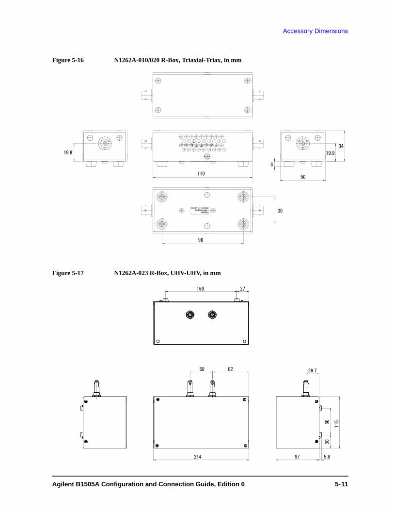
Accessory Dimensions
Figure 5-16 N1262A-010/020 R-Box, Triaxial-Triax, in mm
Figure 5-17 N1262A-023 R-Box, UHV-UHV, in mm
160 27
50 82
214 97
29.7
5.8
115
3060
Agilent B1505A Configuration and Connection Guide, Edition 6 5- 11

Accessory Dimensions
Figure 5-18 N1267A HVSMU/HCSMU Fast Switch, in mm
Figure 5-19 N1269A Ultra High Voltage Connection Adapter, in mm
178
4 - M330
178
4 - M3 30
202
9.7
150
138
175 9.7
5.850
100
134
17
15050
125 12.5
5.8
5- 12 Agilent B1505A Configuration and Connection Guide, Edition 6


