50
Agilent Technologies Agilent Dissolution Tester Driver
Agilent Technologies
Agilent Dissolution Tester Driver
Notices© Agilent Technologies, Inc. 2011
No part of this manual may be reproduced in any form or by any means (including elec-tronic storage and retrieval or translation into a foreign language) without prior agree-ment and written consent from Agilent Technologies, Inc. as governed by United States and international copyright laws.
Manual Part NumberG7900-90001
Edition05/11
Printed in Germany
Agilent TechnologiesHewlett-Packard-Strasse 8 76337 Waldbronn
This product may be used as a com-ponent of an in vitro diagnostic sys-tem if the system is registered with the appropriate authorities and com-plies with the relevant regulations. Otherwise, it is intended only for gen-eral laboratory use.
Warranty
The material contained in this docu-ment is provided “as is,” and is sub-ject to being changed, without notice, in future editions. Further, to the max-imum extent permitted by applicable law, Agilent disclaims all warranties, either express or implied, with regard to this manual and any information contained herein, including but not limited to the implied warranties of merchantability and fitness for a par-ticular purpose. Agilent shall not be liable for errors or for incidental or consequential damages in connection with the furnishing, use, or perfor-mance of this document or of any information contained herein. Should Agilent and the user have a separate written agreement with warranty terms covering the material in this document that conflict with these terms, the warranty terms in the sep-arate agreement shall control.
Technology Licenses The hardware and/or software described in this document are furnished under a license and may be used or copied only in accor-dance with the terms of such license.
Restricted Rights LegendIf software is for use in the performance of a U.S. Government prime contract or subcon-tract, Software is delivered and licensed as “Commercial computer software” as defined in DFAR 252.227-7014 (June 1995), or as a “commercial item” as defined in FAR 2.101(a) or as “Restricted computer soft-ware” as defined in FAR 52.227-19 (June 1987) or any equivalent agency regulation or contract clause. Use, duplication or dis-closure of Software is subject to Agilent Technologies’ standard commercial license terms, and non-DOD Departments and Agencies of the U.S. Government will
receive no greater than Restricted Rights as defined in FAR 52.227-19(c)(1-2) (June 1987). U.S. Government users will receive no greater than Limited Rights as defined in FAR 52.227-14 (June 1987) or DFAR 252.227-7015 (b)(2) (November 1995), as applicable in any technical data.
Safety Notices
CAUTION
A CAUTION notice denotes a hazard. It calls attention to an operating procedure, practice, or the like that, if not correctly per-formed or adhered to, could result in damage to the product or loss of important data. Do not proceed beyond a CAUTION notice until the indicated condi-tions are fully understood and met.
WARNING
A WARNING notice denotes a hazard. It calls attention to an operating procedure, practice, or the like that, if not correctly performed or adhered to, could result in personal injury or death. Do not proceed beyond a WARNING notice until the indi-cated conditions are fully under-stood and met.
Contents
Contents
1 Installation and Configuration 5
Introduction 6Site requirements 8Connecting your tester to the PC 9
2 Installation of the tester driver software 13
Installation of the tester driver software 14
3 Using the driver features 25
Using the driver features 26
4 Configuring a UV-visible ChemStation’s dissolution testing method for tester control 31
Monitoring of tester data 32Using UV-visible ChemStation dissolution software to control the tester parameter 33
5 Using the USB to Serial Adapter interface 35
Using the USB to Serial Adapter interface 36
6 Dissolution tester driver software removal 39
Dissolution tester driver software removal 40
7 Specifications 43
Specifications 44
8 Parts and Supplies 45
Parts and Supplies 46
3

Contents
4

1Installation and Configuration
Introduction 6
Site requirements 8
Connecting your tester to the PC 9
5Agilent Technologies
1 Installation and ConfigurationIntroduction
Introduction
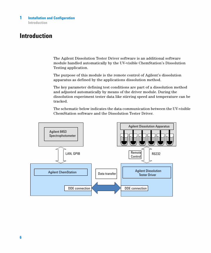
The Agilent Dissolution Tester Driver software is an additional software module handled automatically by the UV-visible ChemStation’s Dissolution Testing application.
The purpose of this module is the remote control of Agilent’s dissolution apparatus as defined by the applications dissolution method.
The key parameter defining test conditions are part of a dissolution method and adjusted automatically by means of the driver module. During the dissolution experiment tester data like stirring speed and temperature can be tracked.
The schematic below indicates the data communication between the UV-visible ChemStation software and the Dissolution Tester Driver.
6
Installation and Configuration 1Introduction
Before the Agilent Dissolution Tester Driver can be applied it must be installed on the PC the UV-visible ChemStation is residing. In addition the configuration for automatic launch is required.
The bath driver software is directly linked to a single tester. If multiple testers are connected for multibath operation each tester requires an execution of its own instance.
According to the testers attached, different tester driver can be applied for different models or tester brands.
NOTE This manual only describes the Agilent tester driver software features. Compatible tester models are Agilent 708-DS, VK7000, VK7010 and VK 7020.
7
1 Installation and ConfigurationSite requirements
Site requirements
An online dissolution system controlled by the UV-visible ChemStation’s Dissolution testing software including the dissolution tester must be installed.
The PC must have a CD-ROM drive for the installation.
The driver software is supported on Windows XP, Windows VISTA and Windows 7 in their professional editions.
The PC must have a serial RS232 communication port for interfacing the tester. The interface cable (RS 232 Tester connection cable (single tester) (p/n 5075-0552)) has a 9 pin Sub-D male connector to the PC and a 25 pin Sub-D male connector to the tester.
NOTE If no direct 9 pin RS232 connection is available, alternatively USB connections in combination with the Agilent converter interface (USB to Serial Adapter (p/n 8121-1013)) can be applied. For details of the installation of the converter interface see “Using the USB to Serial Adapter interface” on page 36.
8
Installation and Configuration 1Connecting your tester to the PC
Connecting your tester to the PC
Configuration with a single tester
1 Setup and align your tester first. Make sure it is in an operable condition and connected to line power.
2 Switch the PC and the tester off.
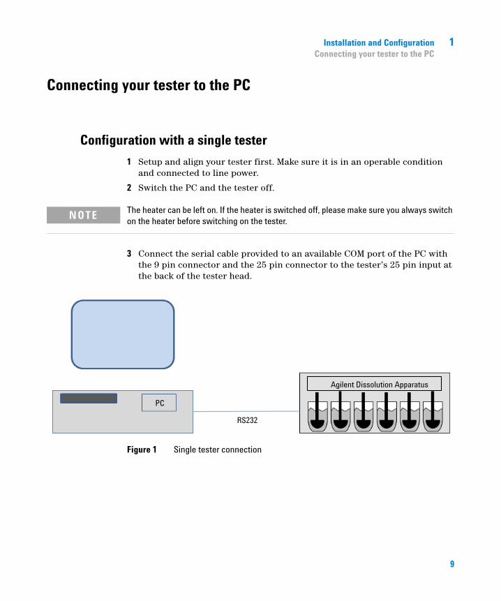
3 Connect the serial cable provided to an available COM port of the PC with the 9 pin connector and the 25 pin connector to the tester’s 25 pin input at the back of the tester head.
Figure 1 Single tester connection
NOTE The heater can be left on. If the heater is switched off, please make sure you always switch on the heater before switching on the tester.
9
1 Installation and ConfigurationConnecting your tester to the PC
Configurations with multiple testers
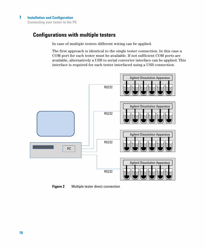
In case of multiple testers different wiring can be applied.
The first approach is identical to the single tester connection. In this case a COM port for each tester must be available. If not sufficient COM ports are available, alternatively a USB to serial converter interface can be applied. This interface is required for each tester interfaced using a USB connection.
Figure 2 Multiple tester direct connection
10
Installation and Configuration 1Connecting your tester to the PC
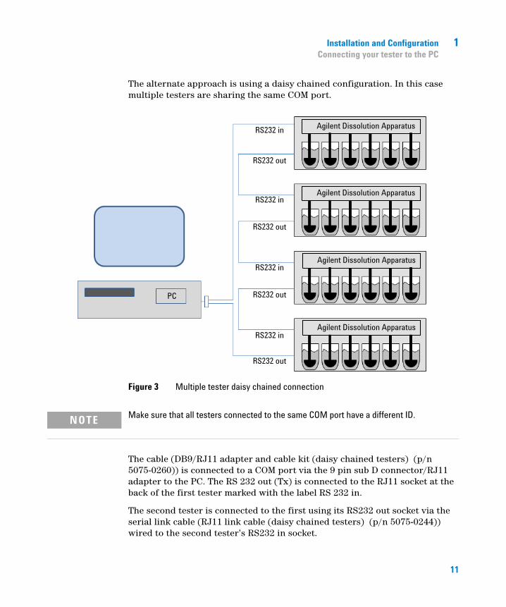
The alternate approach is using a daisy chained configuration. In this case multiple testers are sharing the same COM port.
Figure 3 Multiple tester daisy chained connection
The cable (DB9/RJ11 adapter and cable kit (daisy chained testers) (p/n 5075-0260)) is connected to a COM port via the 9 pin sub D connector/RJ11 adapter to the PC. The RS 232 out (Tx) is connected to the RJ11 socket at the back of the first tester marked with the label RS 232 in.
The second tester is connected to the first using its RS232 out socket via the serial link cable (RJ11 link cable (daisy chained testers) (p/n 5075-0244)) wired to the second tester’s RS232 in socket.
NOTE Make sure that all testers connected to the same COM port have a different ID.
11
1 Installation and ConfigurationConnecting your tester to the PC
Additional testers are hooked up the same way using the last wired testers RS232 out connecting to their RS232 in port.
The last tester’s RS232 out port is connected to the 9 pin sub D connector/adapter’s RS232 in (Rx) connection using the cable (DB9/RJ11 adapter and cable kit (daisy chained testers) (p/n 5075-0260)).
NOTE In this configuration all testers must be switched on for a proper operation!
12
2Installation of the tester driver software
Installation of the tester driver software 14
Single Bath Dissolution Testing Configuration 17
Multibath Dissolution Testing Configuration 18
Details of the command line entry 20
13Agilent Technologies

2 Installation of the tester driver softwareInstallation of the tester driver software
Installation of the tester driver software
1 Log on to the PC of the target system with local administrator rights.
2 Insert the Dissolution Tester Driver Software CD and run the Setup.exe program.
NOTE If you get the warning dialog below, press Run to continue.
14
Installation of the tester driver software 2Installation of the tester driver software
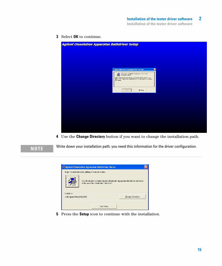
3 Select OK to continue.
4 Use the Change Directory button if you want to change the installation path.
5 Press the Setup icon to continue with the installation.
NOTE Write down your installation path; you need this information for the driver configuration.
15
2 Installation of the tester driver softwareInstallation of the tester driver software
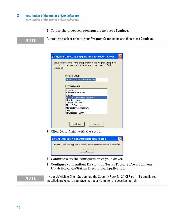
6 To use the proposed program group press Continue.
7 Click OK to finish with the setup.
8 Continue with the configuration of your driver.
9 Configure your Agilent Dissolution Tester Driver Software in your UV-visible ChemStation Dissolution Application.
NOTE Alternatively select or enter your Program Group name and then press Continue.
NOTE If your UV-visible ChemStation has the Security Pack for 21 CFR part 11 compliance installed, make sure you have manager rights for the session launch.
16

Installation of the tester driver software 2Installation of the tester driver software
Single Bath Dissolution Testing Configuration
1 Launch your UV-visible ChemStation in the online mode and switch to the Dissolution Testing mode.
2 Select the Bath command from the Config menu and enter the full qualified driver executable name, C:\Program Files\Agilent\AgtBath.exe /com:1 /address:1 by default.
3 Press OK to save your configuration.
NOTE The entered configuration becomes active only after a new launch of the UV-visible ChemStation’s Dissolution testing modes.
For launching the newly specified driver switch to Standard mode and back to Dissolution Testing.
17
2 Installation of the tester driver softwareInstallation of the tester driver software
Multibath Dissolution Testing Configuration
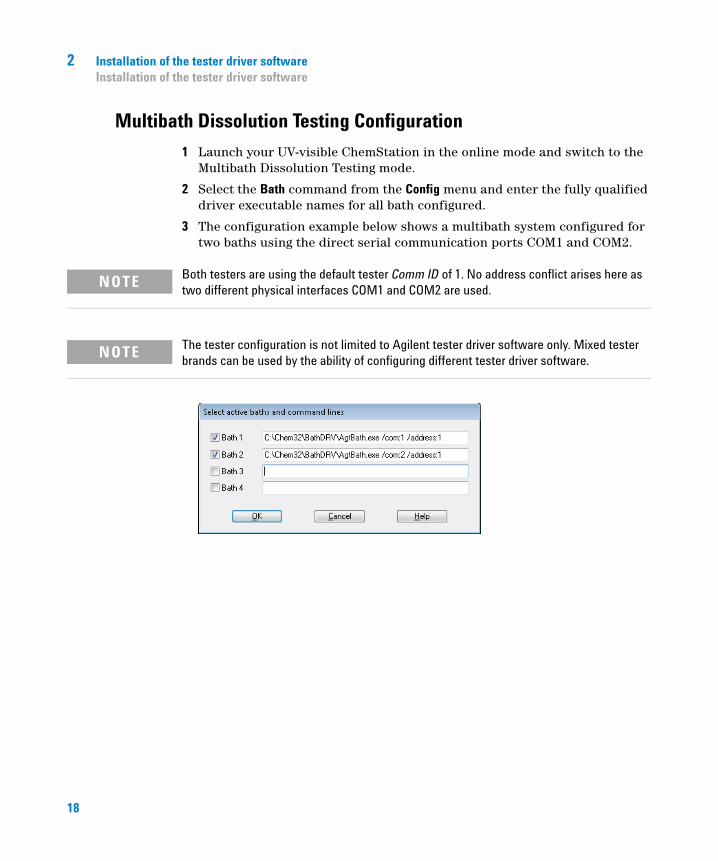
1 Launch your UV-visible ChemStation in the online mode and switch to the Multibath Dissolution Testing mode.
2 Select the Bath command from the Config menu and enter the fully qualified driver executable names for all bath configured.
3 The configuration example below shows a multibath system configured for two baths using the direct serial communication ports COM1 and COM2.
NOTE Both testers are using the default tester Comm ID of 1. No address conflict arises here as two different physical interfaces COM1 and COM2 are used.
NOTE The tester configuration is not limited to Agilent tester driver software only. Mixed tester brands can be used by the ability of configuring different tester driver software.
18
Installation of the tester driver software 2Installation of the tester driver software
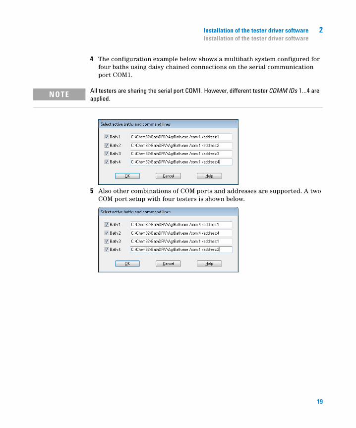
4 The configuration example below shows a multibath system configured for four baths using daisy chained connections on the serial communication port COM1.
5 Also other combinations of COM ports and addresses are supported. A two COM port setup with four testers is shown below.
NOTE All testers are sharing the serial port COM1. However, different tester COMM IDs 1…4 are applied.
19
2 Installation of the tester driver softwareInstallation of the tester driver software
Details of the command line entry
The command line is used for launching the dissolution tester communication software and passing required parameters to this application. The Agilent dissolution tester driver software is a standalone executable piece of software. It can be launched for multiple attached testers using different command line parameters.
By default two additional parameters are added by the UV-visible ChemStation’s dissolution applications. The first is the DDE server name stated as /DDE:<DDE server name>. The DDE server name is automatically generated by the operating system. The second is indicating the dissolution application mode. It is specified as /Mode:single for the dissolution testing mode or /Mode:multi<ID> where <ID> is the bath ID of the multibath dissolution testing mode.
These entries are not displayed with the bath driver configuration command line.
Required Entries
<Driver pathname>
The first entry in the command line dialog is the path name of the driver executable, C:\Program Files\Agilent\AgtBath.exe. Parameters can be added each separated by a blank.
For the Agilent Tester Driver Software two parameters are required.
/com:<value> The com parameter defines the COM port applied for the serial communication to the tester attached. The parameter is preceded by the respective identifier /com: followed by the value for the port used. In this example the parameter /com:1 refers to COM1.
/address:<value> The address parameter is the instrument’s Comm ID on the serial communication line. This parameter can be changed on the local interface of the dissolution tester. The Comm ID parameter can be adjusted using the Instrument Settings dialog of the tester’s Setup menu. The command line syntax of the identifier is /address:. In the above example a tester Comm ID of 1 is configured. The Comm ID 1 is default on the Agilent testers.
The above defined required parameter com and address can be specified in any sequence.
20
Installation of the tester driver software 2Installation of the tester driver software
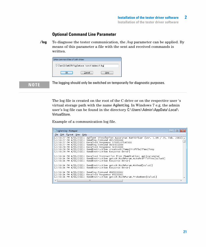
Optional Command Line Parameter
/log To diagnose the tester communication, the /log parameter can be applied. By means of this parameter a file with the sent and received commands is written.
The log file is created on the root of the C drive or on the respective user ‘s virtual storage path with the name Agilent.log. In Windows 7 e.g. the admin user’s log file can be found in the directory C:\Users\Admin\AppData\Local\VirtualStore.
Example of a communication log file.
NOTE The logging should only be switched on temporarily for diagnostic purposes.
21
2 Installation of the tester driver softwareInstallation of the tester driver software
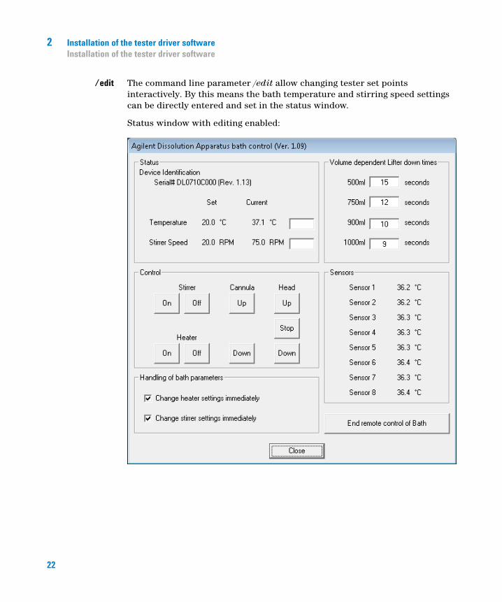
/edit The command line parameter /edit allow changing tester set points interactively. By this means the bath temperature and stirring speed settings can be directly entered and set in the status window.
Status window with editing enabled:
22
Installation of the tester driver software 2Installation of the tester driver software
This is more for testing purposes rather than in actual runs. In typical operation these settings are provided by the method applied.
NOTE Target settings for temperature and stirring speed can be entered using the entry fields adjacent to the current settings.
According to the check marks in the Handling of bath parameters section, the new set points may or may not become active immediately.
The entered set points will appear with a short delay under the Set column. If the change immediately option is checked, the values in the Current column will approach the target set values. This process is fast for changes of the stirring speed but slow for temperature changes.
23

2 Installation of the tester driver softwareInstallation of the tester driver software
24
3Using the driver features
Using the driver features 26
Using the dissolution tester driver software in combination with an automated run 30
25Agilent Technologies
3 Using the driver featuresUsing the driver features
Using the driver features
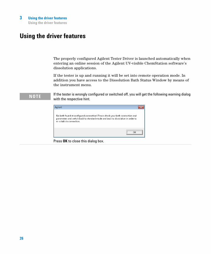
The properly configured Agilent Tester Driver is launched automatically when entering an online session of the Agilent UV-visible ChemStation software’s dissolution applications.
If the tester is up and running it will be set into remote operation mode. In addition you have access to the Dissolution Bath Status Window by means of the instrument menu.
NOTE If the tester is wrongly configured or switched off, you will get the following warning dialog with the respective hint.
Press OK to close this dialog box.
26

Using the driver features 3Using the driver features
After launching the Dissolution Bath Status by going to the Instrument menu and executing the Dissolution Bath Status a window similar to the one shown below will pop up.
If the application is currently indicating its Ready status, the status window can be used executing the following operations using the Control group of the window.
Stirring can be switched on or off by means of the On and Off buttons underneath the Stirrer label.
The heater can be switched on or off using the respective buttons adjacent to the Heater label.
NOTE Make sure the heater is switched on. It has a separate power switch.
27

3 Using the driver featuresUsing the driver features
If the manifold for the probes is installed, the probes can be raised and lowered into the vessel.
If temperature probes for the vessels are installed, individual readings are provided for the medium temperature in the vessel.
A motorized head can be raised and lowered using the Up and Down buttons.
The movement can be stopped immediately by means of the Stop button.
The Dissolution Tester Driver software is automatically terminated, if the dissolution application is closed.
NOTE The vessels must be filled with medium and the manifold must be in its down position. Be aware that the down position is a function of the vessel volume configured.
NOTE Temperatures below 30 °C are not available. Instead “n/a” is displayed.
NOTE Make sure nothing is in the way of the travelling head. Keep off the area between the vessel base and the head.
NOTE For performing a dissolution test run the drive head must be in its down position.
28
Using the driver features 3Using the driver features
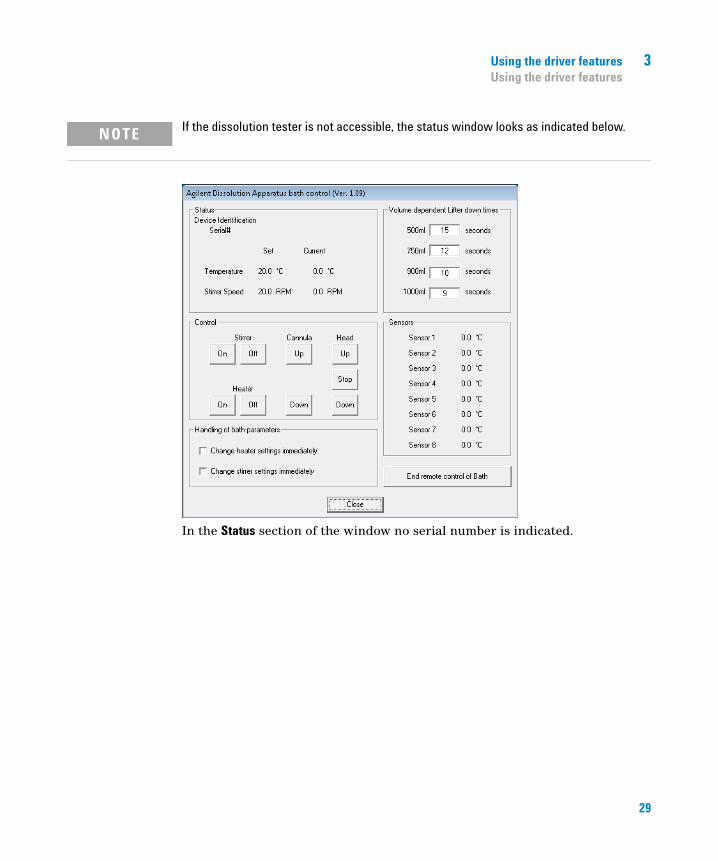
In the Status section of the window no serial number is indicated.
NOTE If the dissolution tester is not accessible, the status window looks as indicated below.
29
3 Using the driver featuresUsing the driver features
Using the dissolution tester driver software in combination with an automated run
Most useful is the driver software in combination with an on-line sampling system. In such a case the tester conditions of the method can be automatically handled by the Agilent UV-visible ChemStation Dissolution software. In addition test relevant conditions like bath temperature, vessel temperatures and stirring speed can be monitored at an adjustable frequency.
The monitoring data are becoming part of a dissolution testing results file. This is very useful diagnostics information in case of unexpected results.
30
4Configuring a UV-visible ChemStation’s dissolution testing method for tester control
Monitoring of tester data 32
Using UV-visible ChemStation dissolution software to control the tester parameter 33
31Agilent Technologies
4 Configuring a UV-visible ChemStation’s dissolution testing method for tester controlMonitoring of tester data
Monitoring of tester data
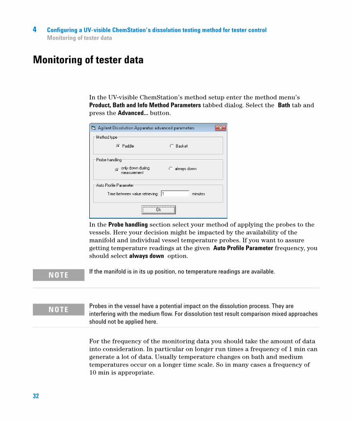
In the UV-visible ChemStation’s method setup enter the method menu’s Product, Bath and Info Method Parameters tabbed dialog. Select the Bath tab and press the Advanced... button.
In the Probe handling section select your method of applying the probes to the vessels. Here your decision might be impacted by the availability of the manifold and individual vessel temperature probes. If you want to assure getting temperature readings at the given Auto Profile Parameter frequency, you should select always down option.
For the frequency of the monitoring data you should take the amount of data into consideration. In particular on longer run times a frequency of 1 min can generate a lot of data. Usually temperature changes on bath and medium temperatures occur on a longer time scale. So in many cases a frequency of 10 min is appropriate.
NOTE If the manifold is in its up position, no temperature readings are available.
NOTE Probes in the vessel have a potential impact on the dissolution process. They are interfering with the medium flow. For dissolution test result comparison mixed approaches should not be applied here.
32
Configuring a UV-visible ChemStation’s dissolution testing method for tester control 4Using UV-visible ChemStation dissolution software to control the tester parameter
Using UV-visible ChemStation dissolution software to control the tester parameter
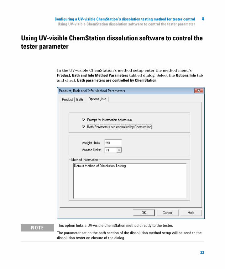
In the UV-visible ChemStation’s method setup enter the method menu’s Product, Bath and Info Method Parameters tabbed dialog. Select the Options Info tab and check Bath parameters are controlled by ChemStation.
NOTE This option links a UV-visible ChemStation method directly to the tester.
The parameter set on the bath section of the dissolution method setup will be send to the dissolution tester on closure of the dialog.
33
4 Configuring a UV-visible ChemStation’s dissolution testing method for tester controlUsing UV-visible ChemStation dissolution software to control the tester parameter
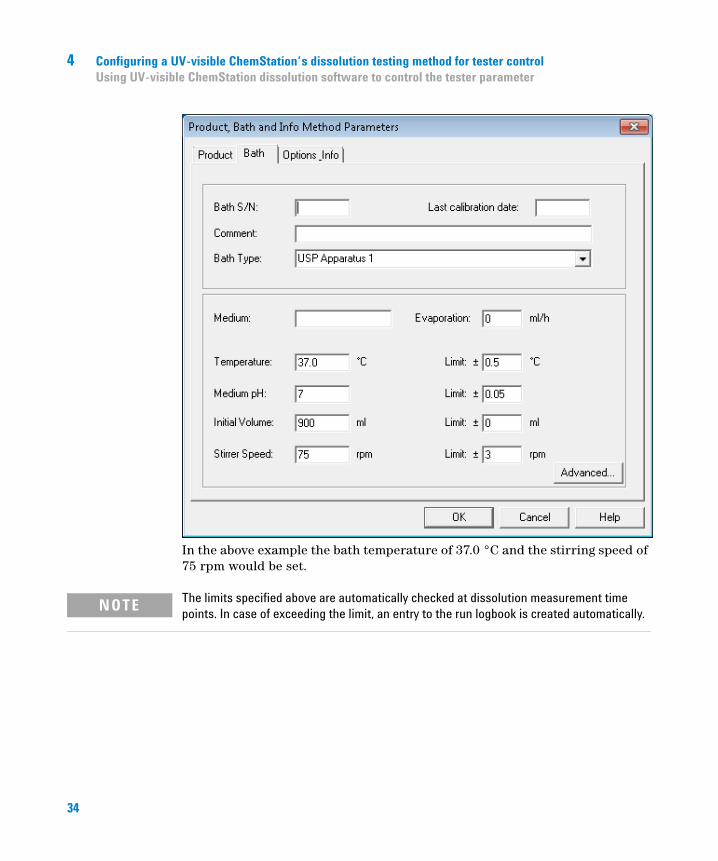
In the above example the bath temperature of 37.0 °C and the stirring speed of 75 rpm would be set.
NOTE The limits specified above are automatically checked at dissolution measurement time points. In case of exceeding the limit, an entry to the run logbook is created automatically.
34
5Using the USB to Serial Adapter interface
Using the USB to Serial Adapter interface 36
35Agilent Technologies
5 Using the USB to Serial Adapter interfaceUsing the USB to Serial Adapter interface
Using the USB to Serial Adapter interface
In case of multiple baths connected to a single PC or if no free COM port is available on your PC the USB to RS232 converter cable (USB to Serial Adapter (p/n 8121-1013)) can be applied.
The converter interface ships with a driver CD-ROM. Please make sure installing this driver before you first connect the interface to your PC.
Instructions are with the User Guide shipping with the interface.
After plugging in the USB to Serial adapter cable, automatically a new com port will be assigned to it.
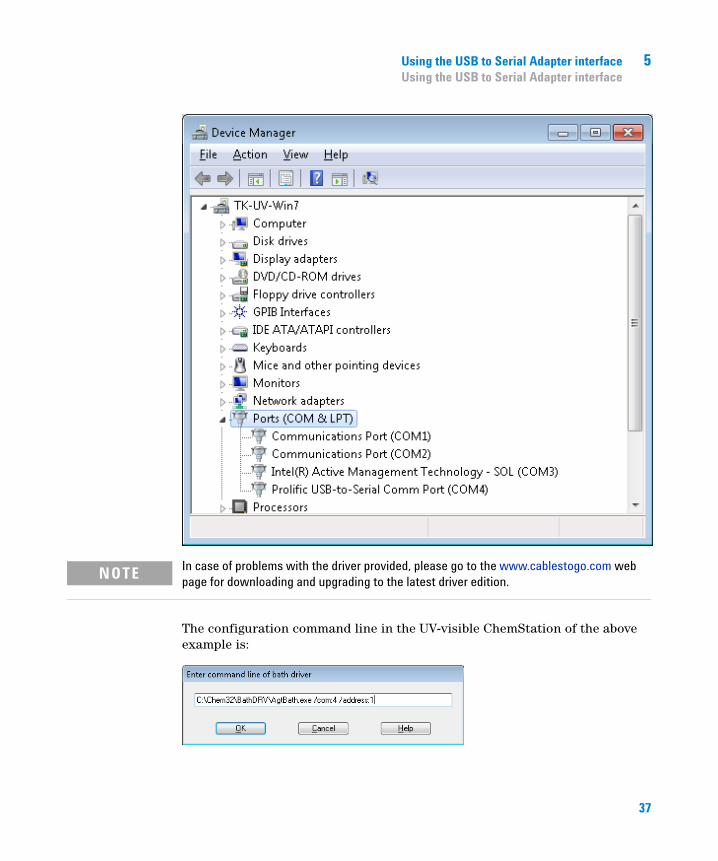
The Windows Device manger can be used for checking the device assignment as well as the proper installation. It should appear under the Ports (COM&LPT) section.
In the example below it appears as “Profilic USB-to-Serial Comm Port (COM4)”.
36
Using the USB to Serial Adapter interface 5Using the USB to Serial Adapter interface
The configuration command line in the UV-visible ChemStation of the above example is:
NOTE In case of problems with the driver provided, please go to the www.cablestogo.com web page for downloading and upgrading to the latest driver edition.
37

5 Using the USB to Serial Adapter interfaceUsing the USB to Serial Adapter interface
38

6Dissolution tester driver software removal
Dissolution tester driver software removal 40
39Agilent Technologies
6 Dissolution tester driver software removalDissolution tester driver software removal
Dissolution tester driver software removal
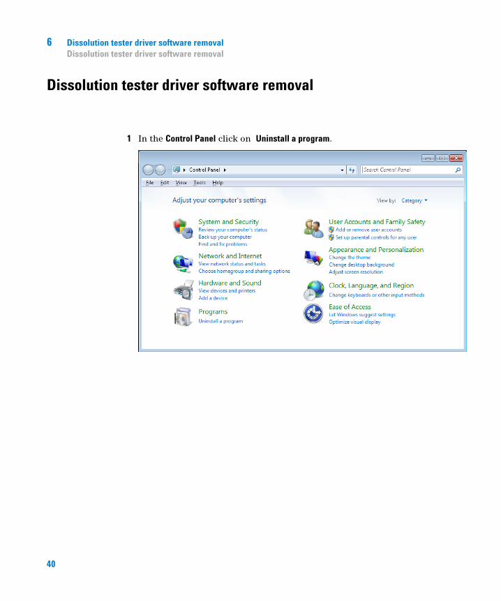
1 In the Control Panel click on Uninstall a program.
40
Dissolution tester driver software removal 6Dissolution tester driver software removal
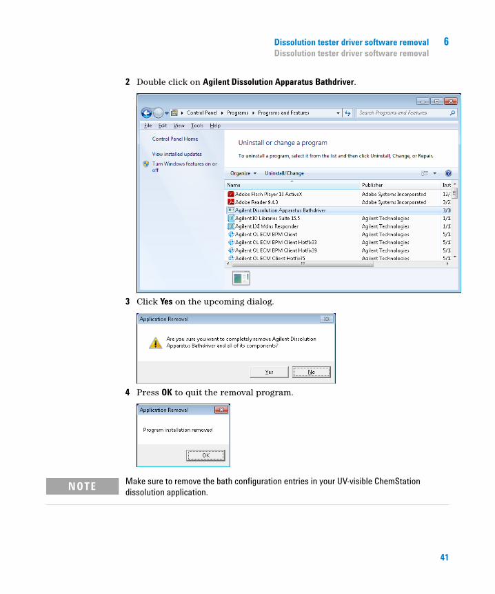
2 Double click on Agilent Dissolution Apparatus Bathdriver.
3 Click Yes on the upcoming dialog.
4 Press OK to quit the removal program.
NOTE Make sure to remove the bath configuration entries in your UV-visible ChemStation dissolution application.
41

6 Dissolution tester driver software removalDissolution tester driver software removal
42
7Specifications
Specifications 44
43Agilent Technologies
7 SpecificationsSpecifications
Specifications
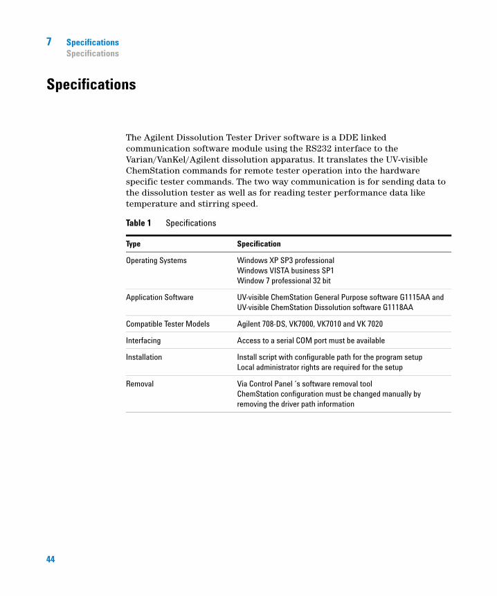
The Agilent Dissolution Tester Driver software is a DDE linked communication software module using the RS232 interface to the Varian/VanKel/Agilent dissolution apparatus. It translates the UV-visible ChemStation commands for remote tester operation into the hardware specific tester commands. The two way communication is for sending data to the dissolution tester as well as for reading tester performance data like temperature and stirring speed.
Table 1 Specifications
Type Specification
Operating Systems Windows XP SP3 professionalWindows VISTA business SP1Window 7 professional 32 bit
Application Software UV-visible ChemStation General Purpose software G1115AA andUV-visible ChemStation Dissolution software G1118AA
Compatible Tester Models Agilent 708-DS, VK7000, VK7010 and VK 7020
Interfacing Access to a serial COM port must be available
Installation Install script with configurable path for the program setupLocal administrator rights are required for the setup
Removal Via Control Panel ‘s software removal toolChemStation configuration must be changed manually by removing the driver path information
44
8Parts and Supplies
Parts and Supplies 46
45Agilent Technologies
8 Parts and SuppliesParts and Supplies
Parts and Supplies
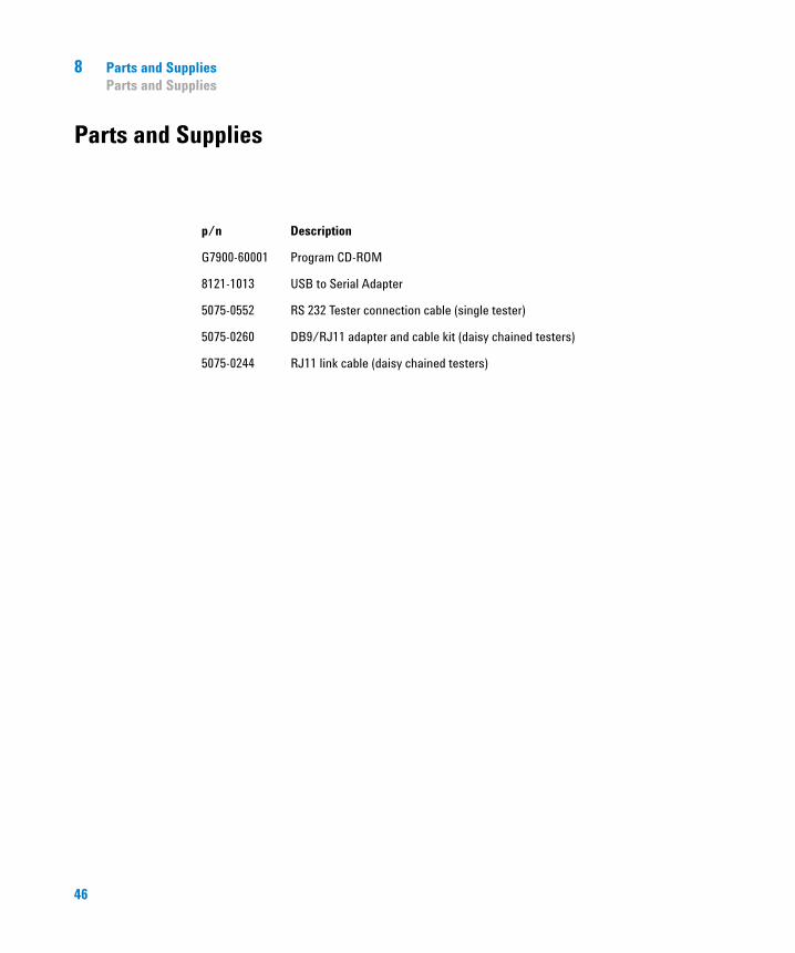
p/n Description
G7900-60001 Program CD-ROM
8121-1013 USB to Serial Adapter
5075-0552 RS 232 Tester connection cable (single tester)
5075-0260 DB9/RJ11 adapter and cable kit (daisy chained testers)
5075-0244 RJ11 link cable (daisy chained testers)
46
Index
Index
Aadapter
USB to serial 36USB to serial 8
address 20
adjustable frequency 30
Agilent VK 7020 44
Agilent VK7000 44
Agilent 708-DS 44
Agilent dissolution apparatus bathdriver 41
Agilent VK7010 44
Agilent.log 21
application mode 20
application software 44
Bbath configuration 41
buttonstop 28
Ccable 46
CD-ROM 8
changing set pointsinteractively 22
COM port 9, 10, 11, 20, 44
COM1 18, 19
COM2 18
COMM ID 19, 20
command line 20
commandbath 18
config menu 18
configuration 5
configuring 16
control panel 44
converterUSB to serial 10
Ddaisy chained 11, 19
data communication 6
DDE server name 20
DDE 44
device assignment 36
diagnose 21
diagnostics 30
dissolution testing mode 20
dissolution apparatus 6
dissolution method 6
dissolution testerlocal interface 20
dissolution testing results 30
down option 32
downloading 37
drive head 28
driver configuration 15
Eexceeding the limit 34
Ffile 21
frequencyadjustable 30
Hheater 27
Iindividual readings 28
installation path 15
installation 5, 8
instrument settings 20
interface cable 8
interfacing 8
Llaunching
automatically 26
limits 34
local administrator 44
log file 21
logging 21
logonadministrator rights 14
Mmanifold 28, 32
measurement time points 34
menuconfig 18
monitoringfrequency 32
motorized head 28lowering 28raising 28
multibath dissolution testing mode 20
multibath dissolution testing 18
47
Index
multibath system 18
multibathdaisy chained 19
Nnew com port
assign 36
Oon-line sampling system 30
online session 26
operating systems 44
Pparameter
address 20COM port 20com 20edit 22identifier 20value 20
probes 28lowering 28raising 28
programuninstall 40
Rready status 27
removal 41
required entries 20
resultsdissolution testing 30unexpected 30
RS232 8
run logbook 34
Sserial communication 20
serial number 29
setup menuinstrument settings 20
setup.exe 14
single bath 17
softwareremoval 40
status window 22
statusready 27
stirring speed 6, 22
stirring 27
stop button 28
Ttemperature probes 28
temperature readings 32
temperature 6, 22, 28
terminatingautomatically 28
tester models708-DS 7VK 7020 7VK7000 7VK7010 7
travelling head 28
Uunexpected results 30
uninstall program 40
upgrading 37
UV-visible ChemStation Dissolution software 44
UV-visible ChemStation General Purpose software 44
UV-visible ChemStation 6, 30
Vvessel temperature probes 32
virtual storage path 21
Wwarning dialog
switched off 26
Windows Device manger 36
Windows 7 8, 21
Windows VISTA 8
Windows XP 8
48

Index
49
www.agilent.com
In This Book
This manual contains information on the Agilent 7900 Dissolution Tester Driver
The manual describes the following:
• Installation and Configuration
• Installation of the software
• Using the driver features
• Configuring a method for tester control
• Interfaces
• Software removal
• Specifications
• Parts and Supply
Agilent Technologies 2011
Printed in Germany 05/11
*G7900-90001**G7900-90001*G7900-90001
Agilent Technologies


