Agilent E6701E/T GSM/GPRS Lab Application and E6704A EGPRS Lab Application Data Sheet For use with the E5515B/C (8960) wireless communication test The Agilent E6701E and E6701T GSM/GPRS (Optional E6704A EGPRS) Lab Applications provide the incredibly successful E5515 (8960) wireless communications test set with a long list of analysis features for RF, applications, mobility, services, and protocol. Whether you design, integrate, debug, or validate wireless devices, the E6701E and E6701T, with their breadth of capabilities, will help you deliver mobile devices that hit your market window. R&D managers – You will be pleasantly surprised by the number of engineers you can enable with a single instru- ment – from RF development all the way to signaling conformance. RF engineers – Get your transmitter and receiver validated before the mobile protocol stack is complete with our non-signaling modes. QA managers – Regression test all your device’s existing functionality including, AMR, SMS/MMS, plus the very latest GSM enhancements such as dual transfer mode (DTM), and the capability to test all of this during handovers and cell (re-)selection. Pre-conformance and conformance engineers – The 8960 can be used in Anite SAS/SAT conformance systems as well as in Agilent’s GS8800 pre-conformance system. Software application engineers – Test simultaneous voice or data connections while sending an SMS or MMS. Test end-to-end data, MMS, video, instant messaging (IM) or push-to-talk over cellular (PoC). Rapidly resolve inter-service or device-to-device interoperability issues with the included Wireless Protocol Advisor PC software for point-and-click simple analysis of mobile and cell protocol messaging from decoded L1 to IP. Latest Features • Dual transfer mode, including enhanced DTM • 2-cell handovers and cell (re-)selection. Requires two instruments • Delayed DL TBF and extended UL TBF, useful for push-to-talk over cellular (PoC) throughput and latency test • Support for (E)GPRS Class 30, 31, 32, and 33 • Combined or non-combined SDCCH calls • Repeating SACCH and FACCH • Multiple PDP contexts
For use with the E5515B/C (8960) wireless communication test
The Agilent E6701E and E6701TGSM/GPRS (Optional E6704A EGPRS)Lab Applications provide the incredibly successful E5515 (8960)wireless communications test setwith a long list of analysis featuresfor RF, applications, mobility, services,and protocol. Whether you design,integrate, debug, or validate wirelessdevices, the E6701E and E6701T,with their breadth of capabilities, will help you deliver mobile devicesthat hit your market window.
R&D managers – You will be pleasantlysurprised by the number of engineersyou can enable with a single instru-ment – from RF development all theway to signaling conformance.
RF engineers – Get your transmitterand receiver validated before themobile protocol stack is completewith our non-signaling modes.
QA managers – Regression test allyour device’s existing functionalityincluding, AMR, SMS/MMS, plus thevery latest GSM enhancements suchas dual transfer mode (DTM), and the capability to test all of this duringhandovers and cell (re-)selection.
Pre-conformance and conformanceengineers – The 8960 can be used inAnite SAS/SAT conformance systemsas well as in Agilent’s GS8800 pre-conformance system.
Software application engineers –Test simultaneous voice or data connections while sending an SMS orMMS. Test end-to-end data, MMS,video, instant messaging (IM) orpush-to-talk over cellular (PoC). Rapidly resolve inter-service ordevice-to-device interoperabilityissues with the included WirelessProtocol Advisor PC software forpoint-and-click simple analysis ofmobile and cell protocol messagingfrom decoded L1 to IP.
Latest Features• Dual transfer mode, including
enhanced DTM
• 2-cell handovers and cell (re-)selection. Requires two instruments
• Delayed DL TBF and extended UL TBF, useful for push-to-talk over cellular (PoC) throughput and latency test
• Support for (E)GPRS Class 30, 31, 32, and 33
• Combined or non-combined SDCCH calls
• Repeating SACCH and FACCH
• Multiple PDP contexts
Audio Functionality
• Choice of speech encoded on downlink TCH: none, echo, 300 Hz sine, 1 kHz sine, 3 kHz sine, PRBS-15, multi-tone, or custom
• GSM analog audio measurement (audio level, distortion, frequency,SINAD)
Receiver Measurements
• GSM bad frame indication (BFI)
• GSM FACCH frame erasure rate (FER)
• GSM burst-by-burst bit error ratio(fast BER)
• GSM bit error ratio (BER)
• (E)GPRS multislot bit error ratio (BER)
• (E)GPRS multislot block error ratio(BLER)
• AMR in-band frame error (AMR I-FER)
• USF BLER (assigned)
• USF BLER (unassigned)
Transmitter Measurements(Maximum of two uplink timeslots)
• Multislot transmit power
• EGPRS multislot-tolerant modulation accuracy (peak, rms, 95th percentile and sample EVM; frequency, magnitude, and phase errors; origin offset suppression; and IQ imbalance)
• GSM/GPRS multislot-tolerant frequency error
• GSM/GPRS multislot-tolerant phase error (peak and rms with confidence limits)
• Multislot-power versus time (burst mask comparison with settable masks)
• Burst timing
• Multislot-tolerant output RF spectrum due to modulation and switching
• IQ tuning
• GSM decoded audio level
• Dynamic power
• Frequency stability
• Enhanced measurement reports
• Packet enhanced measurementreports
• 3G neighbor SACCH measurements
Instruments
• Audio generator
• General-purpose spectrum monitor
• Data throughput monitor
• GSM multi-tone audio
Protocol Functionality
• Dual transfer mode (DTM)
• 2-cell handovers and cell (re)selection (using two instruments)
• (E)GPRS PS data channel
• GSM CS data channel
• Frequency hopping on TCH or PDTCH
• AMR voice echo
• Highly configurable GSM and (E)GPRS SMS
• RRLP layer for A-GPS and E-OTD
• Protocol event trigger outputs
• Protocol logging with WPA software
• SACCH and PACCH measurement reports
2
Figure 1. Verify your EGPRS device’s performance under various levels of downlink corruption withincremental redundancy.
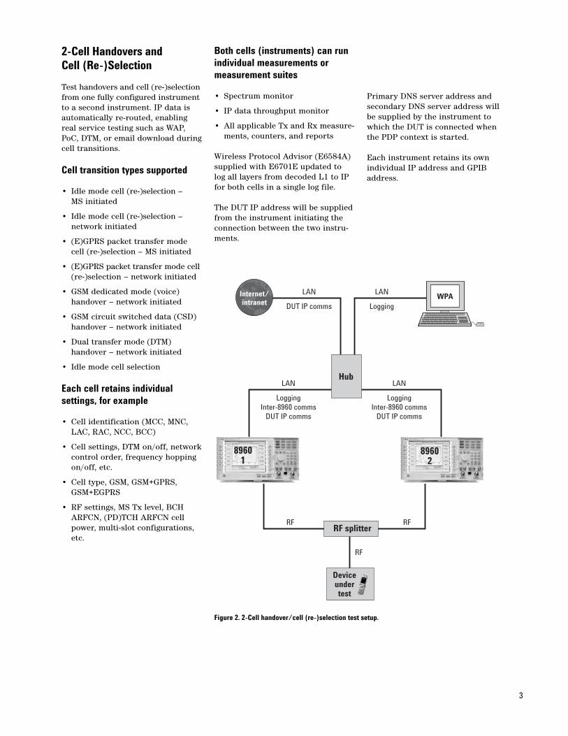
2-Cell Handovers and Cell (Re-)Selection
Test handovers and cell (re-)selectionfrom one fully configured instrumentto a second instrument. IP data isautomatically re-routed, enablingreal service testing such as WAP,PoC, DTM, or email download duringcell transitions.
• Cell settings, DTM on/off, networkcontrol order, frequency hopping on/off, etc.
• Cell type, GSM, GSM+GPRS, GSM+EGPRS
• RF settings, MS Tx level, BCH ARFCN, (PD)TCH ARFCN cell power, multi-slot configurations, etc.
Both cells (instruments) can runindividual measurements ormeasurement suites
• Spectrum monitor
• IP data throughput monitor
• All applicable Tx and Rx measure-ments, counters, and reports
Wireless Protocol Advisor (E6584A)supplied with E6701E updated tolog all layers from decoded L1 to IPfor both cells in a single log file.
The DUT IP address will be suppliedfrom the instrument initiating theconnection between the two instru-ments.
Primary DNS server address andsecondary DNS server address willbe supplied by the instrument towhich the DUT is connected whenthe PDP context is started.
Each instrument retains its ownindividual IP address and GPIBaddress.
3
Figure 2. 2-Cell handover/cell (re-)selection test setup.
Hub
89601
89602
LAN
LoggingInter-8960 comms
DUT IP comms
RF RF
RF
LAN
DUT IP comms
LAN
Logging
LAN
LoggingInter-8960 comms
DUT IP comms
Deviceundertest
RF splitter
Internet/intranet
WPA
Dual Transfer Mode (DTM)
Simultaneous GSM circuit switchedvoice call and (E)GPRS data connec-tion using contiguous timeslots onthe same ARFCN.
• Cell operation setting, DTM on or off
• Enhanced DTM on or off
• DTM operable with active cell settings GPRS or EGPRS
• DTM circuit switched MS Tx level settable from 0 to 31
• Selectable DTM circuit switched timeslot position
• Downlink timeslot count of 2, 3, 4, or 5
• Uplink timeslot count of 2, 3, or 4
• Active cell indicators:
• Connected/Attaching
• Connected/Attached
• Connected/Detaching
• Connected/PDP active
• Connected/Transfer
• Connected/Starting
• Connected/Ending
• Connected/Idle
• GPRS and EGPRS DTM multislot class report display
• Additional limited signaling operating modes
• GPRS BCH+PDTCH+TCH
• EGPRS BCH+PDTCH+TCH
GSM and (E)GPRS FrequencyHopping
Applies to a traffic channel, TCH orPDTCH. The following settings canbe changed when Cell Off operatingmode is selected.
• Cell allocation (CA) table: 1 to 16 settable traffic channel ARFCN(s) to be used within the cell
• Mobile allocation (MA) configuration: selection of manual(user configures MA table entries)or auto (automatically enable every applicable entry in the CA table)
• MA table: 1 to 16 entries settable to indicate which entries within the CA table are used for hopping
The following settings can bechanged at any time.
• Mobile allocation index offset (MAIO): settable between 0 and 15
• Hopping sequence number (HSN): settable between 0 and 63;0 corresponds to a cyclic hopping sequence, 1 to 63 correspond to a pseudo-random hopping sequence
• Measurement ARFCN: settable measurement frequency based on valid entries in the MA table
AMR Voice Echo
• Make MO and MT calls with speech received by the test set looped back to the mobile
• Use stress mode to force the mobile to change codec mode on the uplink as often as allowable
• MS request option configuresinstrument to respond to mobilerequests for codec rate changes
• In call changes of codec set, threshold or hysteresis values via RATSCCH signaling
• Current downlink and uplink AFScodec mode selectable as 4.75 kHz,5.15 kHz, 5.9 kHz, 6.7 kHz, 7.4 kHz,7.95 kHz, 10.2 kHz, 12.2 kHz, or stress mode
• Current downlink and uplink AHScodec mode selectable as 4.75 kHz,5.15 kHz, 5.9 kHz, 6.7 kHz, 7.4 kHz, 7.95 kHz, or stress mode
• AFS codec set: one to four codecsselectable as 4.75 kHz, 5.15 kHz, 5.9 kHz, 6.7 kHz, 7.4 kHz, 7.95 kHz,10.2 kHz, or 12.2 kHz
• AHS codec set: one to four codecs selectable as 4.75 kHz, 5.15 kHz, 5.9 kHz, 6.7 kHz, 7.4 kHz, or 7.95 kHz
• Threshold values: zero to three AFS threshold values or zero to three AHS threshold values are settable between 0 and 31.5 dB in0.5 dB steps; number of thresholdvalues settable is dependent on number of selected codec modes in the AFS or AHS codec set
• Hysteresis values: one to three AFS hysteresis values or one to three AHS hysteresis values are settable between 0 and 7.5 dB in 0.5 dB steps; number of thresholdvalues settable is dependent on number of selected codec modes in the AFS or AHS codec set
4
5
GSM and (E)GPRS SMS
Test WAP push, MMS, EMS messaging,and concatenated SMS with expandedGSM and (E)GPRS SMS functionality.
Use the 8960’s HTTP SMS interfacesto connect via Ethernet to a SMSgateway using industry standardprotocols. Use tools provided by theSMS gateway to automate messageconfiguration and content generationfor all types of MT SMS messages.Two instruments can be linked viaSMS gateway to enable phone tophone MMS test.
MT point-to-point SMS
• Determine the state of the last MTmessage sent as either idle, send, ack, nack, or reject
• Choose to send either GSM or (E)GPRS SMS
• Send UCS2 and binary MT SMS configured using a custom data GPIB command or send one of two fixed ASCII text messages or configure a custom ASCII text message using GPIB (TP-UD)
Fixed message 2: Agilent Technologies, your partner in wireless solutions
• Configure the message type of any MT SMS as SMS-DELIVER, SMS-SUBMIT-REPORT, or SMS-STATUS-REPORT with the option to configure the SMS-SUBMIT-REPORT as RP-ERR (negative) or RP-ACK (positive)
MO point-to-point SMS
• Choose to receive either GSM or (E)GPRS SMS
• Loop back MO SMS to the mobile as a new message
• View on the test set’s display all types of MO SMS received, including header content, as an ASCII string or string of hexadecimal characters
• Determine the header content of any MO SMS using GPIB queries for TP-DA, TP-DL, TP-DCS, TP-UDHI, TP-PID, TP-SRR, and TP-MR
• Determine the content of any MO SMS including header content andlength, filler data, and message content using GPIB queries
• Determine when MO SMS has been received by the test set usingGPIB interrupt or polling mechanisms
• SMS-SUBMIT-REPORT: respond automatically to an MO SMS or manually construct report and report type (RP-ACK or RP-ERR) and send when desired using GPIB
• SMS-STATUS-REPORT: send automatically when requested by the mobile in an MO SMS or manually construct and send when desired using GPIB
• Be sure to capture all concatenatedMO SMS by using message queuing
GSM cell broadcast SMS
• Send up to three messages simultaneously
• Send one of two fixed ASCII text messages or configure a custom ASCII text message or custom data message using GPIB
Fixed message 1:The quick brown fox jumps over the lazy dog
Fixed message 2:This instrument provides functional testing of broadcast SMS by sending up to three broadcast messages to the device under test. Two fixed messages and a user-defined message are available for selection. The secondfixed message spans multiple pages.
Figure 3. Test your device’s SMS performancewith configurable MO and MT SMS.
6
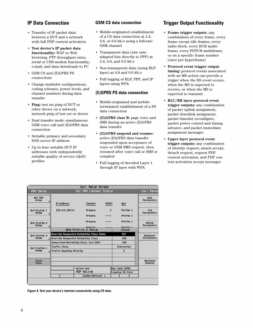
IP Data Connection
• Transfer of IP packet data between a DUT and a network with full PDP context activation
• Test device’s IP packet data functionality: WAP or Web browsing, FTP throughput rates, serial or USB modem functionality,e-mail, and data downloads to PC
• GSM CS and (E)GPRS PS connections
• Change multislot configurations, coding schemes, power levels, andchannel numbers during data transfer
• Ping: test set ping of DUT or other device on a network, network ping of test set or device
• Dual transfer mode: simultaneousGSM voice call and (E)GPRS data connection
• Settable primary and secondary DNS server IP address
• Up to four settable DUT IPaddresses with independentlysettable quality of service (QoS)profiles
GSM CS data connection
• Mobile-originated establishment of a CS data connection at 2.4, 4.8, or 9.6 kb/s using a full-rate GSM channel
• Transparent data (raw rate-adapted bits directly to PPP) at 2.4, 4.8, and 9.6 kb/s
• Non-transparent data (using RLP layer) at 4.8 and 9.6 kb/s
• Full logging of RLP, PPP, and IP layers using WPA
(E)GPRS PS data connection
• Mobile-originated and mobile-terminated establishment of a PS data connection
• (E)GPRS class B: page voice and SMS during an active (E)GPRS data transfer
• (E)GPRS suspend and resume: active (E)GPRS data transfer suspended upon acceptance of voice or GSM SMS request, then resumed after voice call or SMS iscomplete
• Full logging of decoded Layer 1 through IP layer with WPA
Trigger Output Functionality
• Frame trigger outputs: any combination of every frame, everyframe except idle frames, every radio block, every BCH multi-frame, every PDTCH multiframe, or on a specific frame number (once per hyperframe)
• Protocol event trigger output timing: protocol events associatedwith an MS action can provide a trigger when the BS event occurs, when the MS is expected to receive, or when the MS is expected to transmit
• RLC/RR layer protocol event trigger outputs: any combination of packet uplink assignment, packet downlink assignment, packet timeslot reconfigure, packet power control and timing advance, and packet immediate assignment messages
• Upper layer protocol event trigger outputs: any combination of identity request, attach accept, detach request, request PDP context activation, and PDP con-text activation accept messages
Figure 4. Test your device’s internet connectivity using CS data.
7
Integrated GSM and(E)GPRS Functionality
• Switch between GSM, GPRS or EGPRS serving cells
• Switch between data and voice connections without losing camp or attach
• Establish a voice or data connection after initial (E)GPRS attach
• Send SMS while on a voice call
• Send SMS while a PS data connection is active
• Initiate a voice call while a PS data connection is active; data transfer is suspended and resumes after the voice call is terminated
• Dual transfer mode (DTM),including enhanced DTM
GSM Functionality
Mobile station power output levelcontrol: meets GSM phase one andphase two power control levels
Traffic channels: TCH/FS–FR, EFR,HR, AFS, and AHS speech modes
Downlink PDTCH: one, two, three,four or five timeslots on the samePDTCH ARFCN with one or twoPDTCH amplitudes settable between 0 and 55 dB below BCHamplitude; amplitudes in adjacenttimeslots selectable as off, PRL(power reduction level) one, or PRL two
8
EGPRS Functionality
Multislot classes supported: 1 through 12 plus 30, 31, 32, and 33
Control channels: BCH on timeslot 0 on any ARFCN in any band
Downlink PDTCH: one, two, threefour or five timeslots on the samePDTCH ARFCN with one or twoPDTCH amplitudes user-settablebetween 0 and 42 dB below BCHamplitude; amplitudes in adjacenttime slots user-selectable as off,PRL (power reduction level) one orPRL two
GSM TCH parameters
• Settable downlink TCH power including power in adjacent bursts,uplink band, channel number, andpower level
• Channel modes of FR, EFR, AMR, and HR, plus HR subchannel of 0 or 1
• Settable uplink timeslot of 0 to 7
• Settable timing advance of 0 to 63
• Mobile loopback of off, type A, type B, or type C as defined in ETSI 04.14 or 3GPP 44.014
• First corrupted symbol settable between 1 and 148
• Number of symbols to corrupt settable between 1 and 148
• Corruption pattern selectable as all zeros, all ones, or invert
RLC/MAC protocol control
• Retransmission MCS switching: on or off
• Retransmissions before MCS switch: settable from 1 to 500
• Downlink resegmentation: on or off
• NACK good blocks: off or settablefrom 0.1 to 100%
• Window size: selectable from minimum or maximum
• EGPRS supplementary polling (ESP): selectable from (4 sub-bullets), 00-RRBP field invalid (nopolling), 01-RRBP field valid, extended Ack/Nack type FPB, 10-RRBP field valid, extended Ack/Nack type NPB, 11-RRBP field valid, NPB with meas reports
• MAC control: medium access control mode dynamic, dynamic (auto), fixed or extended dynamic,settable USF value, settable assigned USF value of 0 to 100 per-cent, selectable unassigned USF, random, or manual
• Handover control: packet time-slot reconfigure off or on, packet power timing advance off or on
• Uplink packet ACK/NACKinterval (EGPRS): 1 to 1023
• RLC/MAC header: off or on in GPRS BCH+PDTCH and EGPRS BCH+PDTCH operating modes
• Relative reserved block period (RRBP): settable from 0 to 3
• Uplink frame segmentation:asymmetric or symmetric
• EGPRS link quality measurementmodes: no measurements (00), interference measurements for timeslots 0-7 (01), bit error probability (BEP) measurements for allocated timeslots (10) or interference (alternate timeslots 0-3 and 4-7), and BEP (11) as defined in ETSI 05.08 or 3GPP 45.008
LLC protocol control
• FCS for BLER: valid or corrupt
• Payload patterns in ETSI B or for BLER with corrupt FCS: all zeros, all ones, alternate bits, alternate pairs, alternate quads, PRBS-15, fixed 2B (hex), custom, GMM information for BLER
GMM protocol control
• Attach accept: selectable GMM cause, reject IMSI for non-GPRS services off or on
• Attach reject: selectable GMM cause, reject all attach attempts off or on
• Detach request: selectable GMM cause
• Identity request: IMSI, IMEI, IMEISV, TMSI
SM protocol control
• Activate PDP context accept:override requested reliability class off or on with selectable value, selectable subscribed reliability class, includes acknowledged LLC
• Activate PDP context reject: selectable SM cause
E-OTD and A-GPS Functionality
• Partially customizable RRPL layer
• Configure and send measure position request and assistance data messages from the test set
• Ensure assistance data messages are acknowledged by the DUT
• Receive and display RRLP protocol error messages
• Retrieve parameters from the last measure position response message from the DUT
• GPIB access only
• The ESG series of RF signal generators and E4406A VSA transmitter tester also have E-OTD and A-GPS functionality that can be used with the 8960 test set
• ULTS UMTS location test system for A-GPS performance analysis of GSM/(E)GPRS mobile devices available through Spirent Communications at www.spirentcom.com
• Refer to Configuring the GSM/GPRS Lab Application for E-OTD Performance Testingapplication note (literature number 5988-8458EN) at www.agilent.com/find/e6701d
WPA Logging Software
Allows real-time protocol logging of GSM, GPRS, EGPRS, W-CDMA,and cdma2000 messages as well aspost-capture analysis of signaling.Please refer to the E6584A WirelessProtocol Advisor data sheet atwww.agilent.com/find/e6584a
Technical Specifications
These specifications apply to the following:
• E6701E GSM/GPRS Lab Application, revision E.01.XXoperating on E5515C mainframessupplied after November 2006
• E6701T GSM/GPRS Special HighData Rate Lab Application, revision T.02.xx operating on E5515C mainframe with Special High Data Rate hardwaresupplied after November 2006
• E6704A EGPRS Lab Application Extension
Depending on exact configuration,earlier E5515C and E5515B instruments may require hardwareupgrade to obtain certain features and capability. Features which mayrequire hardware upgrades include:spectrum monitor, E6704A EGPRSlab application extension, and RF out only port.
CAUTION: Loading an applicationonto your E5515 test set that is notcompatible with your E5515’s hard-ware revision can cause your E5515to lock up. For information on appli-cation/E5515 compatibility go tohttp://www.agilent.com/find/E5515and select the relevant link (eitherE5515B Release Notes or E5515CRelease Notes.) Always refer to thisinformation before loading an applica-tion.
The E6701T Lab Application specifiedperformance for all parameters communicated in this data sheetand the referred to E1968A datasheet is 25 °C ±5 °C. The 6701Toperating conditions are 0 to 35 °C.
All other technical specificationsand operating modes are included in the E1968A GSM/GPRS/EGPRSmobile test application data sheeton the Web atwww.agilent.com/find/e1968a
Transmitter and receiver measurement specifications
The time until a measurement times-out and returns control to the usercan be set independently for eachmeasurement. All measurementsreturn a measurement integrity resultindicating the accuracy and useful-ness of each measurement’s results.
Frequency coverage and amplitude range
Unless otherwise noted, all specifi-cations apply to frequencies of 450to 496 MHz, 700 to 960 MHz, and 1.7to 1.99 GHz, signals with peak inputpower at the test set’s RF IN/OUTnot higher than +37 dBm and temperatures of 0 to +55 °C. Inputsignal transmit power (defined asthe average power over the usefulpart of the burst) at the test set’s RF IN/OUT must be within ±3 dB of the test set’s expected power forwarranted performance.
12
All EGPRS features and capabilities are enabledthough optional E6704A license.
Receiver measurement specifications
GSM bad frame indication (BFI)measurement
Standards reference: bad frameindication on TCH/FS as per 3GPP51.010-1, section 14.1.1
Types of signals measured: GSMcarrier (TCH/FS) modulated withrandom data sent at 11 dB above thereference sensitivity level, SACCHand silence descriptor (SID) framessent at 20 dB above the referencesensitivity level with the mobile configured to signal bad frames andusing discontinuous transmission(DTX)
Minimum input level: all uplink signals at test set’s RF IN/OUT musthave transmit power ≥ –30 dBm
Mobile loopback: type A as definedin ETSI 04.14 or 3GPP 44.014
Speech frames delay: settablebetween 1 and 15
Numerical results: undetected badframe rate, number of frames sam-pled, number of SIDs sent, numberof undetected bad frames, numberof SIDs marked as BFI
Multi-measurement capabilities: 1 to 999,999 frames sampled
Concurrency capabilities: GSM BFImeasurements can be made concur-rently with all other measurements
Supplemental characteristics
Measurement resolution: 0.001 percent
AMR in-band frame error (I-FER)measurement data:
• Standards reference: reference sensitivity - TCH/AFS-INB as per 3GPP 51.010-1 section 14.2.19, reference sensitivity - TCH/AHS-INB as per 3GPP 51.010-1 section 14.2.20, TCH loop without signal-ing of erased frames for in-band channel error as per 3GPP 51-010-1 section 5.1.7a
• Types of signal measured:reference sensitivity of AMR channel with cycled sequence of CMI and CMC bits
• Minimum input level: all uplink signals at test set’s RF IN/OUT must have transmit power = –30 dBm
• Speech frames loopback delay: settable between 0 and 10
• Change period: settable period between codec mode changes, between 1 and 100