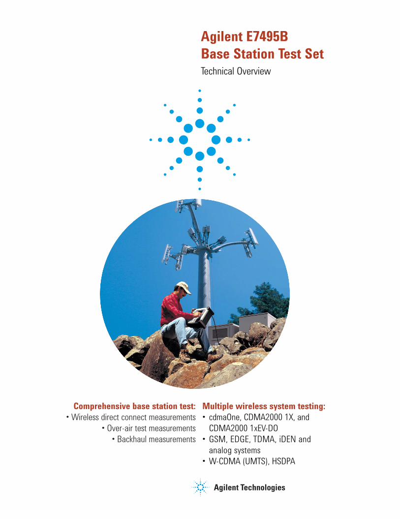
Agilent E7495B Base Station Test Set Technical Overview Comprehensive base station test: • Wireless direct connect measurements • Over-air test measurements • Backhaul measurements Multiple wireless system testing: • cdmaOne, CDMA2000 1X, and CDMA2000 1xEV-DO • GSM, EDGE, TDMA, iDEN and analog systems • W-CDMA (UMTS), HSDPA
Transcript
Agilent E7495B Base Station Test SetTechnical Overview
Comprehensive base station test:• Wireless direct connect measurements
• Over-air test measurements• Backhaul measurements
Multiple wireless system testing:• cdmaOne, CDMA2000 1X, and
CDMA2000 1xEV-DO• GSM, EDGE, TDMA, iDEN and
analog systems• W-CDMA (UMTS), HSDPA
2
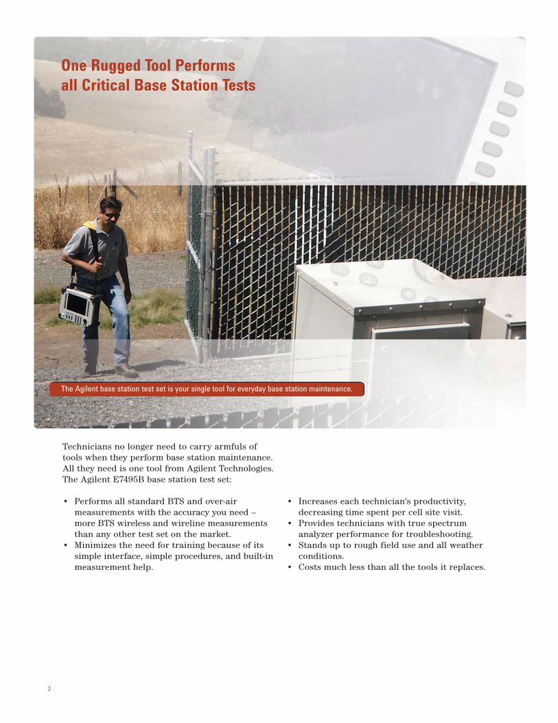
Technicians no longer need to carry armfuls oftools when they perform base station maintenance.All they need is one tool from Agilent Technologies.The Agilent E7495B base station test set:
• Performs all standard BTS and over-air measurements with the accuracy you need – more BTS wireless and wireline measurements than any other test set on the market.
• Minimizes the need for training because of its simple interface, simple procedures, and built-inmeasurement help.
• Increases each technician's productivity, decreasing time spent per cell site visit.
• Provides technicians with true spectrum analyzer performance for troubleshooting.
• Stands up to rough field use and all weather conditions.
• Costs much less than all the tools it replaces.
One Rugged Tool Performs all Critical Base Station Tests
The Agilent base station test set is your single tool for everyday base station maintenance.
3
Agilent E7495B Base Station Test Set
Compact Flash and PCMCIA card slot providesfor easy transfer of data to your PC.
Rubber bumpers help protect the unit from rough environments.
Large buttons enable easy navigation – even with gloves on.
High resolution, transflective color display stays viewable in direct sunlight and at wide viewing angles.
Magnesium alloy case provides strong, lightweight protection for internal components.
Help button displays step-by-step instructions for measurements.
Inside the case, extensive RF shielding helps reduce interference that could impact measurement accuracy.
Backlit keys, protected by a water-resistant rubber membrane, make it easy to perform tests under all lighting and weather conditions.
Battery light changes color to indicate battery life.
4
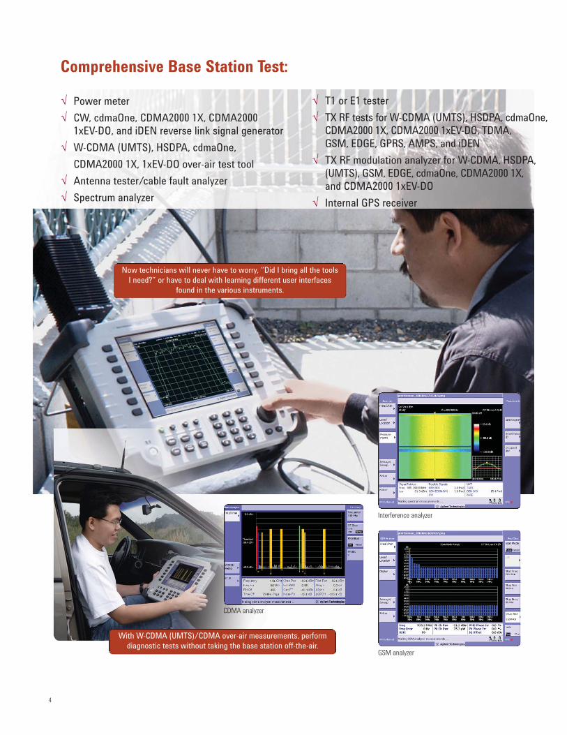
Comprehensive Base Station Test:
Now technicians will never have to worry, “Did I bring all the toolsI need?” or have to deal with learning different user interfaces
found in the various instruments.
With W-CDMA (UMTS)/CDMA over-air measurements, perform diagnostic tests without taking the base station off-the-air.
CDMA analyzer
GSM analyzer
√ T1 or E1 tester
√ TX RF tests for W-CDMA (UMTS), HSDPA, cdmaOne,CDMA2000 1X, CDMA2000 1xEV-DO, TDMA,GSM, EDGE, GPRS, AMPS, and iDEN
Power meter Replaces the need to carry a separate power meter, Accurate power settings help networks operatesimplifying maintenance and shortening site visits. at optimum capacity – reducing coverage holes Additionally, using an appropriate power sensor and minimizing the effects of interference.enables technicians to make power measurementsof microwave links.
CW, iDEN, cdmaOne, CDMA2000 1X, Provides the technician with a source to conduct Reverse link testing helps to ensure network and CDMA2000 1xEV-DO reverse sensitivity measurements. Additionally, allows a service quality. link signal generator technician to perform component level characterization
utilizing simultaneous spectrum analysis and built-in RF and CDMA sources.
W-CDMA (UMTS), HSDPA Provides fast measurements in less than five minutes. Problem areas can be identified without cdmaOne, andCDMA2000 1X Enables time for proactive maintenance and makes interrupting service.over-air test tool pole top testing practical.
Antenna tester with vector Lets your technicians evaluate one of the primary A healthy antenna and feed line networknetwork analysis capability BTS (node B) trouble spots in a matter of minutes. Dual yields improved voice quality, better system• cable tests • swept insertion loss port insertion loss allows technicians to sweep various reliability and reduced dropped calls.• distance to fault • swept insertion gain components like filters, duplexers, amps and more.
Spectrum analyzer Provides necessary functionality so your technicians Quick interference detection leads to don’t need to carry a separate spectrum analyzer. Built-in improved quality of service.masks and markers make it easy to use. Industry leading low noise figure receiver is capable of measuring downto –150 dBm, allowing technicians to identify and pull out low level, intermittent rogue interferers.
T1 or E1 Identifies and diagnoses T1 or E1 problems. Dual Fewer wireline problems mean reducedchannel capability allows “loop-back” measurements. service problems and down time.
Channel scanner for CDMA, W-CDMA Provides easy to interpret bar graph display The channel scanner quickly identifies improper (UMTS), cdmaOne, CDMA2000 1X, illustrating channel power versus frequency of user power levels that can adversely affect networkCDMA2000 1xEV-DO, TDMA, GSM, defined channels. performance.EDGE, GPRS, AMPS, and iDEN
Internal GPS receiver Provides position location, highly accurate For CDMA networks, the internal GPS receiverfrequency measurements and enables independent helps reduce dropped calls by identifying theverification of base station GPS receiver timing. “island cell” effect – improving the quality of service.
Interference analyzer Allows engineers and technicians to find intermittent, Eliminating interfering signals from the networkinterfering signals using a spectrogram display, signal improves quality of service.strength meter and signal ID capability.
6
The Agilent E7495B is the most functional one-boxtool on the market, eliminating the need for yourtechnicians to carry, manage and learn multipletest tools.
This helps reduce your asset costs, tracking costs, calibration and maintenance costs, and the trainingcosts associated with learning the specifics of separate instruments.
The E7495B has a remarkably short learning curvebecause of its simple interface and accessiblelearning tools. So your engineers and technicians –even those with limited knowledge or experience –will be performing BTS measurements in less time.In turn, experienced engineers can devote more oftheir time resolving chronic coverage problems,planning new sites, and expanding into new services and technologies.
The simple procedures plus exceptionally usablehardware combine to produce shorter net time percell site visit. Now each technician can handle morecell sites and have the time to conduct more proactive maintenance.
The field-rugged design means less downtime,more field time.
Engineered-in extensibility lets you do more todayand tomorrow. Today, a variety of I/O ports permitdata sharing with other tools and software. All feature upgrades will be done through hardwareor firmware inside the case, preserving thesingle-case convenience and reliability.
Dramatically Increase Technician Productivity and Maintain High Quality of Service
Having the most frequently used BTS tools in one boxdramatically increases your technicians' productivity.
7
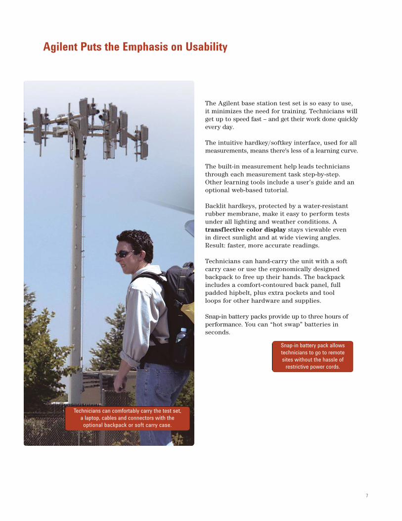
The Agilent base station test set is so easy to use,it minimizes the need for training. Technicians willget up to speed fast – and get their work done quicklyevery day.
The intuitive hardkey/softkey interface, used for allmeasurements, means there's less of a learning curve.
The built-in measurement help leads techniciansthrough each measurement task step-by-step.Other learning tools include a user’s guide and anoptional web-based tutorial.
Backlit hardkeys, protected by a water-resistantrubber membrane, make it easy to perform testsunder all lighting and weather conditions. A transflective color display stays viewable even in direct sunlight and at wide viewing angles.Result: faster, more accurate readings.
Technicians can hand-carry the unit with a softcarry case or use the ergonomically designed backpack to free up their hands. The backpackincludes a comfort-contoured back panel, fullpadded hipbelt, plus extra pockets and tool loops for other hardware and supplies.
Snap-in battery packs provide up to three hours of performance. You can “hot swap” batteries in seconds.
Agilent Puts the Emphasis on Usability
Technicians can comfortably carry the test set,a laptop, cables and connectors with the
optional backpack or soft carry case.
Snap-in battery pack allows technicians to go to remote sites without the hassle of
restrictive power cords.
8
A single-box measurement solution makes sense only if it can stand up to rough field use and unexpected weather. So we designed theAgilent base station test set to be rugged, durableand weather resistant.
A magnesium alloy case with extensive internal RF shielding protects the components, reducesinterference that could impact measurement accuracy, and makes the test set easy to handleand carry.
Gasketed ports, water-resistant rubber membrane, anddust-proof case design (no fan, no vents) add to theongoing confidence you can have in the measurements. The soft carry case or backpack protects the uniton the way to and from the site.
We know that you'll want to add new capabilitiesas your network evolves. So we made sure that allfunctionality upgrades will be implemented throughfirmware or hardware inside the case. The Agilenttest set grows in functionality without growing insize. The field-rugged design is never compromisedby awkward external modules.
The Agilent E7495B rugged design enables technicians to go anywhere, anytime regardless of the weather.
9
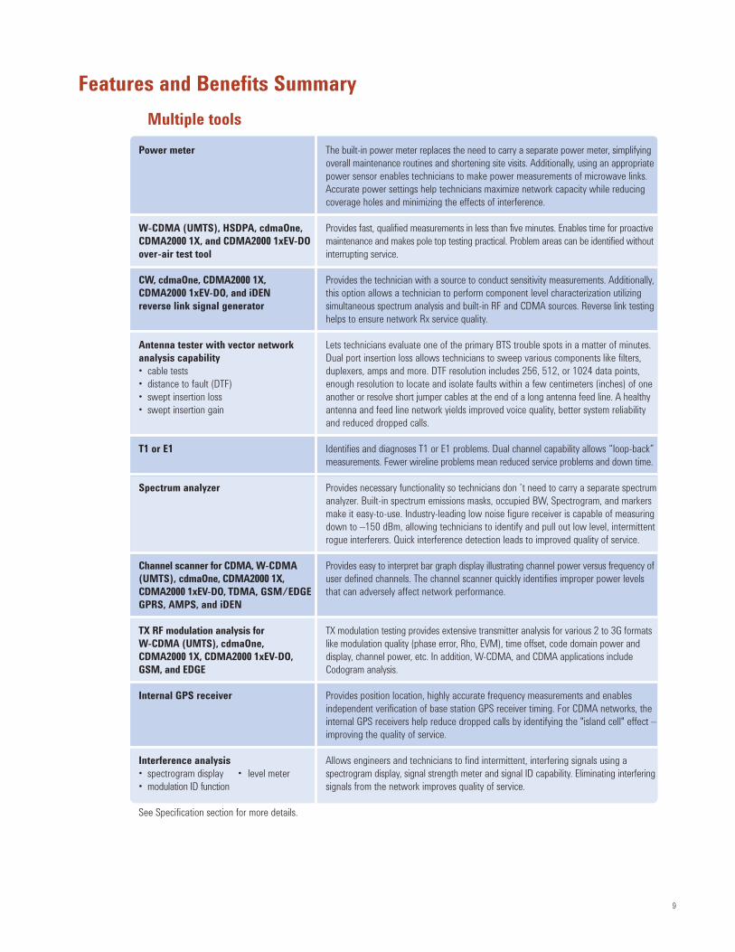
Features and Benefits Summary
Multiple tools
Power meter The built-in power meter replaces the need to carry a separate power meter, simplifyingoverall maintenance routines and shortening site visits. Additionally, using an appropriatepower sensor enables technicians to make power measurements of microwave links. Accurate power settings help technicians maximize network capacity while reducing coverage holes and minimizing the effects of interference.
W-CDMA (UMTS), HSDPA, cdmaOne, Provides fast, qualified measurements in less than five minutes. Enables time for proactiveCDMA2000 1X, and CDMA2000 1xEV-DO maintenance and makes pole top testing practical. Problem areas can be identified withoutover-air test tool interrupting service.
CW, cdmaOne, CDMA2000 1X, Provides the technician with a source to conduct sensitivity measurements. Additionally, CDMA2000 1xEV-DO, and iDEN this option allows a technician to perform component level characterization utilizing reverse link signal generator simultaneous spectrum analysis and built-in RF and CDMA sources. Reverse link testing
helps to ensure network Rx service quality.
Antenna tester with vector network Lets technicians evaluate one of the primary BTS trouble spots in a matter of minutes. analysis capability Dual port insertion loss allows technicians to sweep various components like filters, • cable tests duplexers, amps and more. DTF resolution includes 256, 512, or 1024 data points, • distance to fault (DTF) enough resolution to locate and isolate faults within a few centimeters (inches) of one • swept insertion loss another or resolve short jumper cables at the end of a long antenna feed line. A healthy• swept insertion gain antenna and feed line network yields improved voice quality, better system reliability
and reduced dropped calls.
T1 or E1 Identifies and diagnoses T1 or E1 problems. Dual channel capability allows “loop-back” measurements. Fewer wireline problems mean reduced service problems and down time.
Spectrum analyzer Provides necessary functionality so technicians don ’t need to carry a separate spectrumanalyzer. Built-in spectrum emissions masks, occupied BW, Spectrogram, and markers make it easy-to-use. Industry-leading low noise figure receiver is capable of measuring down to –150 dBm, allowing technicians to identify and pull out low level, intermittentrogue interferers. Quick interference detection leads to improved quality of service.
Channel scanner for CDMA, W-CDMA Provides easy to interpret bar graph display illustrating channel power versus frequency of(UMTS), cdmaOne, CDMA2000 1X, user defined channels. The channel scanner quickly identifies improper power levels CDMA2000 1xEV-DO, TDMA, GSM/EDGE that can adversely affect network performance.GPRS, AMPS, and iDEN
TX RF modulation analysis for TX modulation testing provides extensive transmitter analysis for various 2 to 3G formats W-CDMA (UMTS), cdmaOne, like modulation quality (phase error, Rho, EVM), time offset, code domain power and CDMA2000 1X, CDMA2000 1xEV-DO, display, channel power, etc. In addition, W-CDMA, and CDMA applications include GSM, and EDGE Codogram analysis.
Internal GPS receiver Provides position location, highly accurate frequency measurements and enables independent verification of base station GPS receiver timing. For CDMA networks, the internal GPS receivers help reduce dropped calls by identifying the "island cell" effect –improving the quality of service.
Interference analysis Allows engineers and technicians to find intermittent, interfering signals using a • spectrogram display • level meter spectrogram display, signal strength meter and signal ID capability. Eliminating interfering• modulation ID function signals from the network improves quality of service.
See Specification section for more details.
10
Features and Benefits Summary continued
Ease-of-use
Transflective color display Speeds up measurement readings because the display remains viewable in darkness, shade and direct sunlight.
Single hardkey user interface Provides easy navigation to perform quick and accurate measurements – even with gloves on.
Backlit keys Makes it easier to perform tests under all lighting and weather conditions.
Built-in measurement help Provides step-by-step instructions for measurements.
Rugged design
Magnesium alloy case Provides a lightweight yet strong enclosure; enhances heat distribution and RF shielding.
Water-resistant rubber membrane Enables technicians to go anywhere, anytime – regardless of the weather. key pad and sealed display Seals out water and dirt to help ensure measurement performance.
Dust-free case design (no vents or fan) Keeps the unit free of moisture and dirt.
Gasketed ports Protects components from moisture and harsh weather.
Wide operating temperature range Performs well even in extreme cold and hot conditions.–10 to 50 °C/14 to 122 °F
Entensive internal RF shielding Reduces RF interference that could impact measurement results.
Rubber bumpers Protects the unit while in rugged field environments.
Extensible
Flexible architecture Easily upgradeable to meet future network needs without growing in size.
Remote monitoring Allows technicians to remotely monitor problematic base stations from the comfort of their own desk.
Upgradeable Upgradeable in the field. With license key enabled upgrades, to test set does notneed to go back to the factory for upgraded funcationality
Linux operating system Provides a safe stable and efficient operation system.
Compact Flash, PCMCIA card slot, Makes saving and transferring measurement results to your PC or network quick and easy.and LAN connection Enables data to be easily captured and transmitted to your network.
Antenna test post processing tool Post processing software enables easy data collection and report generation
File export Allows you to easily save data to Microsoft® Excel files and images to PNG files for use with a PC.
See Specification section for more details.
11
Specifications describe the instrument’s warranted performance and are valid overthe entire operating/environmental range unless otherwise noted.
Characteristics and specifications are show as follows:• Bold type indicates a warranted, hard specification• Normal type indicates a nominal value. Nominal values are design center values
and are not normally tested during the manufacturing process• Supplemental characteristics are intended to provide additional information
useful in applying the instrument by giving typical, but not warranted, perform-ance parameters. These characteristics are show in italics or labelled as "typical," or "usable to."
General specificationsUnless otherwise noted the following specifications apply to allmeasurements/tools using port 2.
Frequency accuracy:Using internal time base: ≤ ± 1 ppm with > 15 minute warm-upInternal time base aging: ± 1 ppm aging/yearWith GPS lock for: > 15 minutes: ≤ ± 0 .03 ppm
Input frequency range: 10 MHz to 2700 MHz
Usable to 500 KHz (specifications and typical values do not apply below 375 MHz unless otherwise noted)
Maximum input level: +20 dBm (.1 W), +50 dBm w/supplied attenuatorMaximum input power without
damaging instrument: 100 W (with external attenuator)1W (without attenuator)
Frequency and time reference:Can use internal timebase or external signal:
Displayed average noise level: –150 dBm (30 Hz RBW, 375 MHz to 1.5 GHz)Port 2 VSWR: < 2:1
Antenna/cable analyzer1
Frequency range: 375 to 2500 MHzFrequency resolution: < 500 Hz Immunity to interfering signals: +20 dBm (with interference rejection turned on)Measurement speed:
Full span: < 17 mS60 MHz span: < 7 mS
Return loss (port1)With ≥ 16 averages: 375 to 2500 MHz
Range: > 40 dBVSWR: < 1.02
Resolution: 0.1 dBDisplay range: –5 to +150 dBSWR range: 1 to 500
Distance to fault (port1)Range (m): 1 m to 300 m
Resolution: (1.5x10⁸) (Vf)/(f2-f1) Hz where VF is relative propagation velocity of cable. (typically 1% of measurement distance)
VSWR: 1 to 500 Number of Data Points: 256, 512, 1024
Example table illustrating the effects of data points and span versus measured distance and resolution (Vf of 93.1%):Data Points Span Measured distance Resolution256 140 MHz 127.68 m 50 cm (19.6 inch)512 140 MHz 255.36 m 50 cm (19.6 inch)512 280 Mhz 127.68 m 25 cm (9.8 inch)1024 560 MHz 127.68 m 12.5 cm (4.9 inch)
Insertion loss (port 1 to port 2) Measurement uses supplied 10 dB padsUsable range: > 100 dB wide range modeAccuracy: ± 1 dB (over 0 to 60 dB, ≥ 16 averages)Average insertion loss (readout) accuracy:
Range: 0 to 40 dBFrequency: 824 to 960 MHz, 1710 to 2170 MHz
(mobile phone bands)Readout resolution: ± 0.1 dB
E7495B Base Station Test Set Specifications
1. For antenna/cable measurements, a short self-calibration procedure must berun prior to making the measurement. For more information about the calibrationprocedures and when they are needed, see sections 2 and 3 in the users manual or use the online help.
12
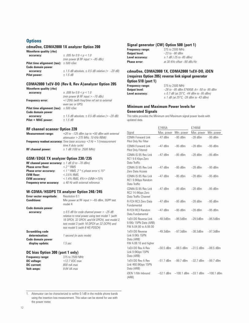
1. Attenuator can be characterized to within 0.1dB in the mobile phone bands using the insertion loss measurement. This value can be stored for use with the power meter.
W-CDMA/HSDPS TX analyzer Option 240/245Error vector magnitude: Resolution 0.1Conditions: Min power at RF input > –65 dBm, 3GPP test
model 4Code domain power
accuracy: ± 0.5 dB for code channel power > –25 dB relative to total power using test model 1 (with 16 DPCH, 32 DPCH, and 64 DPCH), test model 2, test model 3 (with 16 DPCH an 32 DCPH) andtest model 5 (with 8 HS-PDSCH)
Scrambling codedetermination: 1 second (in auto mode)
Code domain powerdisplay update: 1.5 sec
DC bias Option 300 (port 1 only)Frequency range: 375 to 2500 MHzDC voltage: +12.7 VDC maxDC current: 800 mA maxVolt-amps: 9.84 VA max
Signal generator (CW) Option 500 (port 1)Frequency range: 375 to 2500 MHzOutput level: –23 to –90 dBmLevel accuracy: ± 1 dB (-25 to -85 dBm)
Phase error: at 30 KHz offset –90 dBc/Hz
cdmaOne, CDMA2000 1X, CDMA2000 1xEV-DO, iDEN(requires Option 205) reverse link signal generator Option 510 (port 1)Frequency range: 375 to 2500 MHzOutput level: –28 to –95 dBm E7495B; A= -50 to -95 dBmLevel accuracy: ± 0.7 dB (at 25°C, -44 dBm to -95 dBm)
± 1 dB (at 25°C, -28 dBm to -43 dBm)
Minimum and Maximum Power levels for Generated SignalsThis table provides the Minimum and Maximum signal power levels with updated data.
E7495A E7495B
Signal Max. power Min. power Max. power Min. power
CDMA Forward Link –47 dBm –95 dBm –28 dBm –95 dBmPilot Only No Filter
CDMA Forward Link –47 dBm –95 dBm –28 dBm –95 dBmPilot Only Filtered
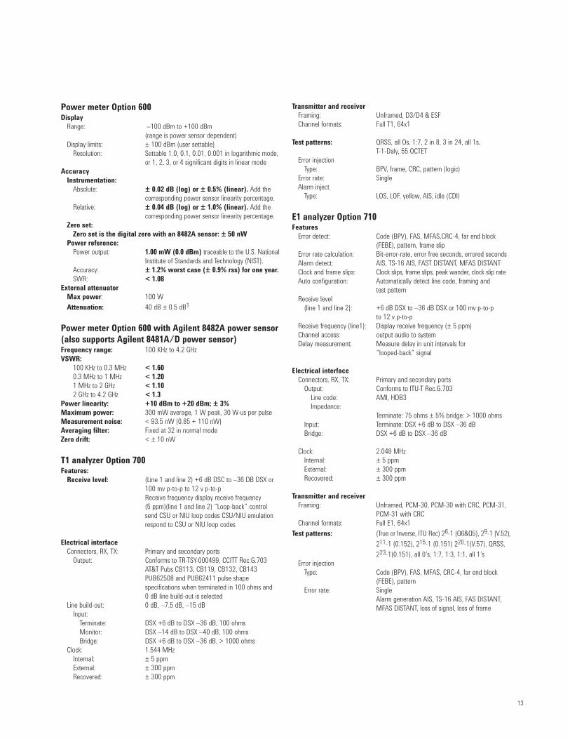
or 1, 2, 3, or 4 significant digits in linear modeAccuracy
Instrumentation:Absolute: ± 0.02 dB (log) or ± 0.5% (linear). Add the
corresponding power sensor linearity percentage.Relative: ± 0.04 dB (log) or ± 1.0% (linear). Add the
corresponding power sensor linearity percentage.Zero set:
Zero set is the digital zero with an 8482A sensor: ± 50 nWPower reference:
Power output: 1.00 mW (0.0 dBm) traceable to the U.S. National Institute of Standards and Technology (NIST).
Accuracy: ± 1.2% worst case (± 0.9% rss) for one year.SWR: < 1.08
External attenuatorMax power: 100 W
Attenuation: 40 dB ± 0.5 dB1
Power meter Option 600 with Agilent 8482A power sensor(also supports Agilent 8481A/D power sensor)Frequency range: 100 KHz to 4.2 GHzVSWR:
100 KHz to 0.3 MHz < 1.600.3 MHz to 1 MHz < 1.201 MHz to 2 GHz < 1.102 GHz to 4.2 GHz < 1.3
Power linearity: +10 dBm to +20 dBm; ± 3%Maximum power: 300 mW average, 1 W peak, 30 W-us per pulseMeasurement noise: < 93.5 nW (0.85 + 110 nW) Averaging filter: Fixed at 32 in normal modeZero drift: < ± 10 nW
T1 analyzer Option 700Features:
Receive level: (Line 1 and line 2) +6 dB DSC to –36 DB DSX or 100 mv p-to-p to 12 v p-to-pReceive frequency display receive frequency (5 ppm)(line 1 and line 2) “Loop-back” control send CSU or NIU loop codes CSU/NIU emulation respond to CSU or NIU loop codes
Electrical interfaceConnectors, RX, TX: Primary and secondary ports
Output: Conforms to TR-TSY-000499, CCITT Rec.G.703 AT&T Pubs CB113, CB119, CB132, CB143PUB62508 and PUB62411 pulse shape specifications when terminated in 100 ohms and 0 dB line build-out is selected
Line build-out: 0 dB, –7.5 dB, –15 dBInput:
Terminate: DSX +6 dB to DSX –36 dB, 100 ohmsMonitor: DSX –14 dB to DSX –40 dB, 100 ohmsBridge: DSX +6 dB to DSX –36 dB, > 1000 ohms
Error detect: Code (BPV), FAS, MFAS,CRC-4, far end block (FEBE), pattern, frame slip
Error rate calculation: Bit-error-rate, error free seconds, errored secondsAlarm detect: AIS, TS-16 AIS, FAST DISTANT, MFAS DISTANTClock and frame slips: Clock slips, frame slips, peak wander, clock slip rateAuto configuration: Automatically detect line code, framing and
test patternReceive level
(line 1 and line 2): +6 dB DSX to –36 dB DSX or 100 mv p-to-p to 12 v p-to-p
Receive frequency (line1): Display receive frequency (± 5 ppm)Channel access: output audio to systemDelay measurement: Measure delay in unit intervals for
“looped-back” signal
Electrical interfaceConnectors, RX, TX: Primary and secondary ports
Output: Conforms to ITU-T Rec.G.703Line code: AMI, HDB3Impedance:
Terminate: 75 ohms ± 5% bridge: > 1000 ohmsInput: Terminate: DSX +6 dB to DSX –36 dBBridge: DSX +6 dB to DSX –36 dB
Operating temperatureSpecified temperature range: –10 to 50 °C; 14 to 122 °F
Storage temperature–40 to 70 °C; –40 to 158 °F
CalibrationCycle: one year
WarrantyDuration: one year
Ordering information – E7495B base station test setStandard test set functionality includes spectrum analysis and antenna measurements
Standard accessories include:• PCMCIA 64 MB flash memory card• AC/DC converter• NI2040AG lithium ion battery• GPS antenna • 10 dB Coaxial attenuator (Q2)• Coax 50 ohm terminated N-male• Open/short M type N• Adapter storage box• Shoulder strap• Documentation (CD ROM)A• 2' M-N to M-N cables (Q2)• 10' M-N to M-N cable• N-female to N-female barrel (Q2)• Adapters
Ordering information – optionsNote: Upgrade options for the E7495A/B use the designation E7495XU before therespective option number.E7495B-200 cdmaOne and CDMA2000 1X TX analyzerE7495B-205 CDMA2000 1xEV-DO analyzer (RX testing requires Option 510,
adds OTA functionality if Option 210 is selected)E7495B-210 cdmaOne, CDMA2000 1X over-the-air test (requires Option 200,
recommend 813 or equivalent)E7495B-270 Interference analyzerE7495B-300 DC BiasE7495B-330 Nortel CDMA base station software (requires Option 200, 510, 600)E7495B-500 CW signal generatorE7495B-510 CW, cdmaOne, CDMA2000 1X, CDMA2000 1xEV-DO, iDEN
(requires Option 205) reverse link signal generatorE7495B-600 Power meter (requires 8481A/D or 8482A power sensors)E7495B-700 T1 analyzerE7495B-710 E1 analyzerE7495B-801 Soft carry caseE7495B-802 BackpackE7495B-803 40 dB 100 W attenuatorE7495B-805 Paper manualE7495B-810 Cellular antenna and pre-selector filter for Option 210E7495B-811 PCS antenna and pre-selector filter for Option 210E7495B-812 Korean PCS antenna and pre-selector filter
(required for Option 210)E7495B-813 Antenna and pre-selector filter (required for Option 250)E7495B-820 Battery pack, external battery charger, DC car adapterE7495B-840 Transit caseE7495B-51B Return to Agilent repairE7495B-50C Return to Agilent calibration8482A/8481A Power sensor
General
15
Additional Agilent Literature
CDAgilent Base Station Test Setliterature number 5988-7189EN
Photo CardAgilent E7495A/B Base Station Test Set:Option 330 Nortel CDMA Base Station Test Softwareliterature number 5988-1783EN
Agilent E7495B Base Station Test Set: E7495B Option 205-1xEV-DO AnalyzerE7495XU Option 205-1xEV-DO Analyzer upgradeE7495B Firmware upgrade 4.0literature number 5989-2846EN
Agilent E7495B Base Station Test Set: E7495B Option 240-W-CDMA Analyzer E7495B Option 245-HSDPA Analyzer E7495B Option 250-W-CDMA/HSDPA OTAliterature number 5989-4060EN
Agilent E7495A/B Base Station Test Set: E7495A/B Option 230-GSM AnanyzerE7495A/B Option 235-EDGE AnalyzerE7495A/B Option 270-Interference Analyzerliterature number 5989-4563EN
For More InformationFor more information about Agilent’s solutions for the communicationsindustry, visit our Web site at www.agilent.com.
For more information about the Agilent E7495B Base Station Test Set, go to: www.agilent.com/find/E7495B
www.agilent.com/find/open
Agilent Open simplifies the process of
connecting and programming test systems
to help engineers design, validate and
manufacture electronic products. Agilent
offers open connectivity for a broad range
of system-ready instruments, open industry
software, PC-standard I/O and global
support, which are combined to more easily
integrate test system development.
Microsoft® and Windows® are U.S. registered trademarks of MicrosoftCorporation.
Pentium® is a U.S. registered trademark of Intel Corporation.
www.agilent.com
For more information on Agilent
Technologies’ products, applications
or services, please contact your local
Agilent office. The complete list is
available at:
www.agilent.com/find/contactus
Phone or Fax
United States:(tel) 800 829 4444(fax) 800 829 4433