Agilent Technologies Agilent G2888A High Temperature Programmable Temperature Vaporizing (HT PTV) Inlet Installation Guide Introduction 2 Installation 4 HT PTV Inlet Specifications 22 Important Safety Warnings 23 This document provides the procedure for installing the Agilent G2888A High Temperature Programmable Temperature Vaporizing (HT PTV) inlet on an Agilent 6890N Gas Chromatograph (GC). NOTE Agilent supports the G2888A HT PTV inlet only when used with the Agilent SimDis System. See your G2887AA SimDis System Reference Manual (G2887-90010) for more information.
Transcript
Agilent G2888A High Temperature Programmable Temperature Vaporizing (HT PTV) Inlet
Installation Guide
Introduction 2
Installation 4
HT PTV Inlet Specifications 22
Important Safety Warnings 23
This document provides the procedure for installing the Agilent G2888A High Temperature Programmable Temperature Vaporizing (HT PTV) inlet on an Agilent 6890N Gas Chromatograph (GC).
NOTE Agilent supports the G2888A HT PTV inlet only when used with the Agilent SimDis System. See your G2887AA SimDis System Reference Manual (G2887-90010) for more information.
Agilent Technologies
Introduction
Parts identification
2
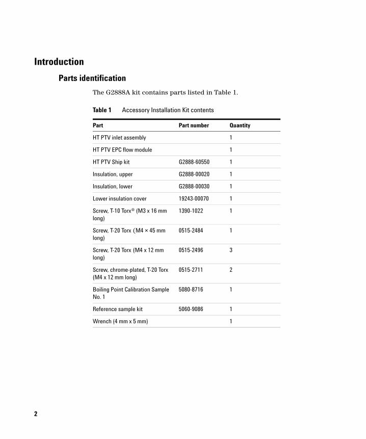
The G2888A kit contains parts listed in Table 1.
Table 1 Accessory Installation Kit contents
Part Part number Quantity
HT PTV inlet assembly 1
HT PTV EPC flow module 1
HT PTV Ship kit G2888-60550 1
Insulation, upper G2888-00020 1
Insulation, lower G2888-00030 1
Lower insulation cover 19243-00070 1
Screw, T-10 Torx® (M3 x 16 mm long)
1390-1022 1
Screw, T-20 Torx (M4 × 45 mm long)
0515-2484 1
Screw, T-20 Torx (M4 x 12 mm long)
0515-2496 3
Screw, chrome-plated, T-20 Torx (M4 x 12 mm long)
0515-2711 2
Boiling Point Calibration Sample No. 1
5080-8716 1
Reference sample kit 5060-9086 1
Wrench (4 mm x 5 mm) 1
Required tools
Installation will require the following tools:
• T-10 Torx screwdriver
• T-20 Torx screwdriver
GC requirements
The 6890N GC must have:
• A back inlet position for the HT PTV inlet
• Firmware revision N.05.05
NOTE If needed, visit the Agilent Web site ( www.agilent.com/chem/ ) to update your firmware.
3
Installation
4
Before beginning, read important safety information beginning on page 23.
Overview
WARNING
Following is an overview of the installation procedure. Subsequent sections explain these steps in detail.
1 Prepare the GC.
2 Remove an existing back inlet and flow module (if needed).
3 Install the EPC flow module and HT PTV inlet assembly.
4 Connect cabling.
5 Return the GC to operating condition.
Prepare the GC
WARNING The first step for this procedure is very important. Working on a GC without first switch-ing off and disconnecting power, and waiting for it to cool, can cause possible burns and exposure to dangerous voltages. For more information, see “Important Safety Warnings” on page 23.
To prepare the GC:
1 Turn off the GC and disconnect its power cord.
2 Wait for the GC to cool.
3 Turn off gas supplies.
4 If installed, remove sample injector(s) and tray.
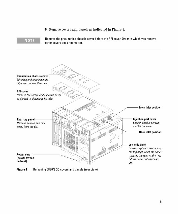
5 Remove covers and panels as indicated in Figure 1.
NOTE Remove the pneumatics chassis cover before the RFI cover. Order in which you remove other covers does not matter.
Figure 1 Removing 6890N GC covers and panels (rear view)
Front inlet position
Back inlet position
Power cord(power switchon front)
Pneumatics chassis coverLift each end to release the clips and remove the cover.
RFI coverRemove the screw, and slide the cover to the left to disengage its tabs.
Rear-top panelRemove screws and pull away from the GC.
Left-side panelLoosen captive screws alongthe top edge. Slide the panel towards the rear. At the top, tilt the panel outward and lift.
Injection port coverLoosen captive screws and lift the cover.
5
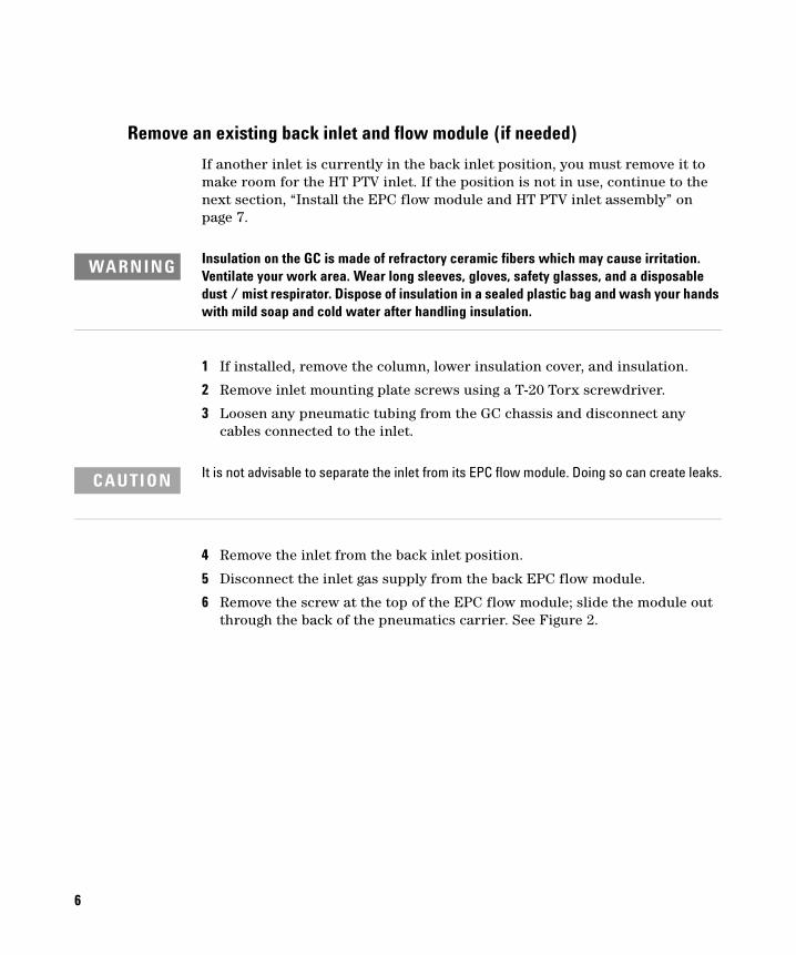
Remove an existing back inlet and flow module (if needed)
6
If another inlet is currently in the back inlet position, you must remove it to make room for the HT PTV inlet. If the position is not in use, continue to the next section, “Install the EPC flow module and HT PTV inlet assembly” on page 7.
WARNING Insulation on the GC is made of refractory ceramic fibers which may cause irritation. Ventilate your work area. Wear long sleeves, gloves, safety glasses, and a disposable dust / mist respirator. Dispose of insulation in a sealed plastic bag and wash your hands with mild soap and cold water after handling insulation.
1 If installed, remove the column, lower insulation cover, and insulation.
2 Remove inlet mounting plate screws using a T-20 Torx screwdriver.
3 Loosen any pneumatic tubing from the GC chassis and disconnect any cables connected to the inlet.
CAUTION It is not advisable to separate the inlet from its EPC flow module. Doing so can create leaks.
4 Remove the inlet from the back inlet position.
5 Disconnect the inlet gas supply from the back EPC flow module.
6 Remove the screw at the top of the EPC flow module; slide the module out through the back of the pneumatics carrier. See Figure 2.
If you are keeping the removed inlet, place all component parts in a sealable plastic bag and store in a safe, dry place.
Figure 2 EPC flow module (rear view)
Remove screw
EPC flow module
Install the EPC flow module and HT PTV inlet assembly
To avoid damaging GC electronics, use a grounded wrist strap (9300-1408) connected to a
CAUTIONbare metal surface on the GC.
EPC flow module
To install the EPC flow module:
1 Slide the EPC flow module into the back inlet position of the pneumatics carrier, lining up ridges and troughs.
2 Insert the ribbon cable connector into the back inlet connector. Lock the connector by moving its tabs to the center until they click into place.
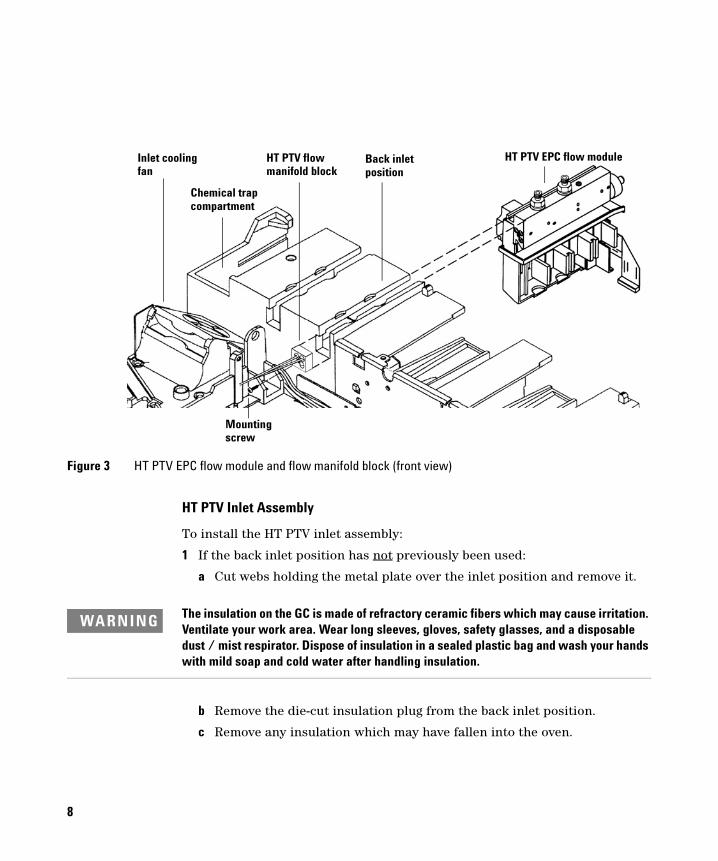
3 Install the 45-mm T-20 Torx screw (0515-2484) from the kit into the top of the EPC flow module. See Figure 3 on page 8.
1 If the back inlet position has not previously been used:
a Cut webs holding the metal plate over the inlet position and remove it.
WARNING The insulation on the GC is made of refractory ceramic fibers which may cause irritation. Ventilate your work area. Wear long sleeves, gloves, safety glasses, and a disposable dust / mist respirator. Dispose of insulation in a sealed plastic bag and wash your hands with mild soap and cold water after handling insulation.
b Remove the die-cut insulation plug from the back inlet position.
c Remove any insulation which may have fallen into the oven.
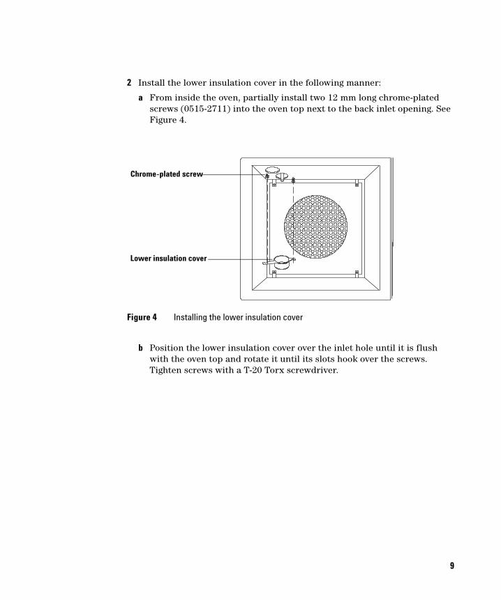
2 Install the lower insulation cover in the following manner:
a From inside the oven, partially install two 12 mm long chrome-plated screws (0515-2711) into the oven top next to the back inlet opening. See Figure 4.
b Position the lower insulation cover over the inlet hole until it is flush with the oven top and rotate it until its slots hook over the screws. Tighten screws with a T-20 Torx screwdriver.
Figure 4 Installing the lower insulation cover
Chrome-plated screw
Lower insulation cover
9
10
3 Assemble pre-formed upper and lower HT PTV inlet insulation pieces: the larger piece installs above the smaller one (see Figure 5).
4 Insert the larger insulation assembly into the inlet opening, with the upper, larger piece rotated as needed to align with the chassis as indicated in Figure 6.
Figure 5 Pre-formed inlet insulation pieces
Figure 6 Installed pre-formed insulation pieces
Upper insulation
Lower insulation
Inlet chassis
Upper insulation
Aligned edges
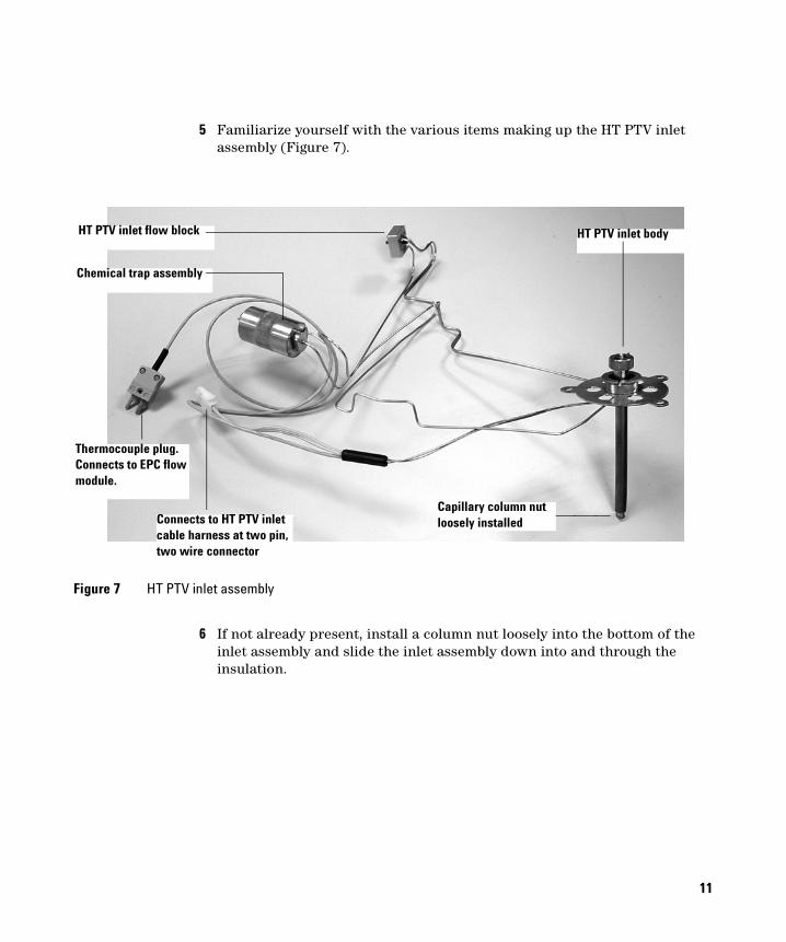
5 Familiarize yourself with the various items making up the HT PTV inlet assembly (Figure 7).
Figure 7 HT PTV inlet assembly
Thermocouple plug. Connects to EPC flow module.
HT PTV inlet flow block
Connects to HT PTV inlet cable harness at two pin, two wire connector
Chemical trap assembly
HT PTV inlet body
Capillary column nut loosely installed
6 If not already present, install a column nut loosely into the bottom of the inlet assembly and slide the inlet assembly down into and through the insulation.
11
12
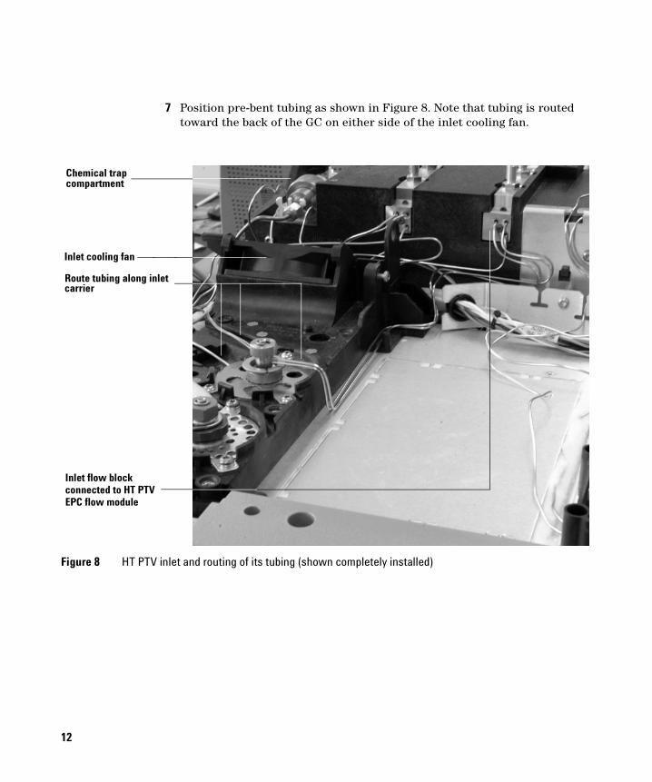
7 Position pre-bent tubing as shown in Figure 8. Note that tubing is routed toward the back of the GC on either side of the inlet cooling fan.
Figure 8 HT PTV inlet and routing of its tubing (shown completely installed)
Route tubing along inletcarrier
Inlet flow blockconnected to HT PTVEPC flow module
Inlet cooling fan
Chemical trapcompartment
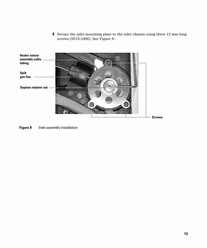
8 Secure the inlet mounting plate to the inlet chassis using three 12 mm long screws (0515-2496). See Figure 9.
Figure 9 Inlet assembly installation
Heater sensorassembly cable
Screws
Splitgas line
Septum retainer nut
tubing
13
14
9 Position the chemical trap inside the compartment directly behind the inlet cooling fan. See Figure 10.
10 Inspect the HT PTV inlet EPC module to make sure its three O-rings are properly seated within their recessed locations. If needed, extra O-rings (0905-1493) are supplied in the ship kit.
11 Secure the flow block to the EPC module using a 16 mm long T-10 Torx screw (1390-1022) and screwdriver. See Figure 3 and Figure 8.
Figure 10 Inlet filter compartment (viewed from instrument rear)
Inlet cooling fan
An existingChemical Trap
HT PTV chemical trapassembly
Connect cabling
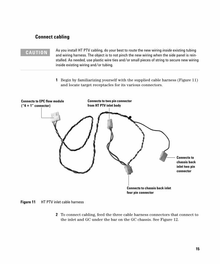
CAUTION As you install HT PTV cabling, do your best to route the new wiring inside existing tubing and wiring harness. The object is to not pinch the new wiring when the side panel is rein-stalled. As needed, use plastic wire ties and/or small pieces of string to secure new wiring inside existing wiring and/or tubing.
1 Begin by familiarizing yourself with the supplied cable harness (Figure 11) and locate target receptacles for its various connectors.
Figure 11 HT PTV inlet cable harness
Connects to EPC flow module (“4 × 1” connector)
Connects to two pin connector from HT PTV inlet body
Connects to chassis back inlet two pin connector
Connects to chassis back inlet four pin connector
2 To connect cabling, feed the three cable harness connectors that connect to the inlet and GC under the bar on the GC chassis. See Figure 12.
15
16
Figure 12 Feed the cable harness
Two pin connectorfrom inlet
Cable harnessconnectors fed upunder bar
Bar
3 Connect the harness to the HT PTV inlet and GC as shown in Figure 13. See also Figure 11.
Figure 13 Cable harness connected to inlet and GC
Cable harness two pin, two wire connector mates withinlet two pin connector
Cable harness four pin, fourwire connector mates to GC
Cable harness two pin,single wire connector mates to GC two pin connector
four pin connector
17
18
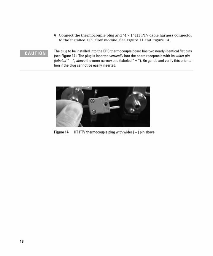
4 Connect the thermocouple plug and “4 × 1” HT PTV cable harness connector to the installed EPC flow module. See Figure 11 and Figure 14.
CAUTION The plug to be installed into the EPC thermocouple board has two nearly-identical flat pins (see Figure 14). The plug is inserted vertically into the board receptacle with its wider pin (labeled “ – “) above the more narrow one (labeled “ + “). Be gentle and verify this orienta-tion if the plug cannot be easily inserted.
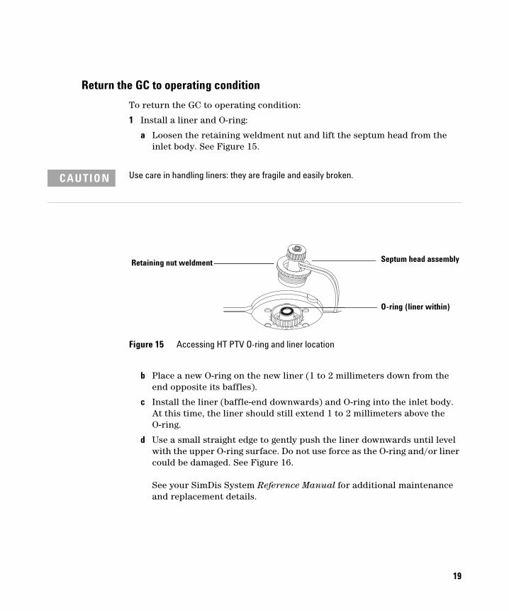
a Loosen the retaining weldment nut and lift the septum head from the inlet body. See Figure 15.
CAUTION Use care in handling liners: they are fragile and easily broken.
b Place a new O-ring on the new liner (1 to 2 millimeters down from the end opposite its baffles).
c Install the liner (baffle-end downwards) and O-ring into the inlet body. At this time, the liner should still extend 1 to 2 millimeters above the O-ring.
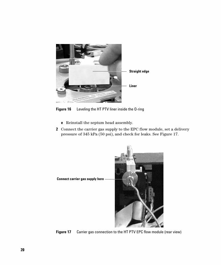
d Use a small straight edge to gently push the liner downwards until level with the upper O-ring surface. Do not use force as the O-ring and/or liner could be damaged. See Figure 16. See your SimDis System Reference Manual for additional maintenance and replacement details.
Figure 15 Accessing HT PTV O-ring and liner location
Retaining nut weldment Septum head assembly
O-ring (liner within)
19
20
e Reinstall the septum head assembly.
2 Connect the carrier gas supply to the EPC flow module, set a delivery pressure of 345 kPa (50 psi), and check for leaks. See Figure 17.
Figure 16 Leveling the HT PTV liner inside the O-ring
Figure 17 Carrier gas connection to the HT PTV EPC flow module (rear view)
Straight edge
Liner
Connect carrier gas supply here
3 Re-install covers and panels on the GC. Be careful to not pinch wiring with the left-side panel. Refer to Figure 1 on page 5 as needed.
4 Restore power to the GC.
5 Using the GC keypad, press [Config] [Back Inlet]. The GC should identify the inlet as a HT PTV inlet. If not, verify its electrical connections.
21
22
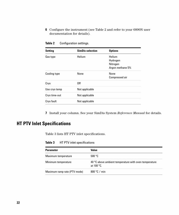
6 Configure the instrument (see Table 2 and refer to your 6890N user documentation for details).
7 Install your column. See your SimDis System Reference Manual for details.
Table 2 Configuration settings.
Setting SimDis selection Options
Gas type Helium Helium Hydrogen Nitrogen Argon methane 5%
Cooling type None NoneCompressed air
Cryo Off
Use cryo temp Not applicable
Cryo time-out Not applicable
Cryo fault Not applicable
HT PTV Inlet Specifications
Table 3 lists HT PTV inlet specifications.
Table 3 HT PTV inlet specifications
Parameter Value
Maximum temperature 500 °C
Minimum temperature 40 °C above ambient temperature with oven temperature at 100 °C.
Maximum ramp rate (PTV mode) 800 °C / min
Important Safety Warnings
There are several important safety notices to keep in mind during installation:
Many internal parts of the instrument carry dangerous voltages
If the instrument is connected to a power source, even if the power switch is off, potentially dangerous voltages exist on:
• Wiring between the power cord recptacle and AC power supply, the AC power supply itself, and wiring from the AC power supply to the power switch.
With the power switch on, potentially dangerous voltages also exist on:
• All electronics boards in the instrument.
• Internal wires and cables connected to these boards.
• Wires for any heater (oven, detector, inlet, valve box, and/or transfer line).
WARNING All these parts are shielded by covers. With the covers in place, it should be difficult to accidentally make contact with dangerous voltages. Unless specifically instructed to, never remove a cover unless the power cord is unplugged.
Electrostatic discharge is a threat to instrument electronics
WARNING If power cord insulation is frayed or worn, replace the cord. Contact your Agilent service representative.
Printed circuit (PC) boards in the instrument can be damaged by electrostatic discharge. Do not touch any of the board unless it is absolutely necessary. If you must handle them, wear a grounded wrist strap and take other antistatic precautions.
23
Many parts are dangerously hot
24
Many parts of the instrument operate at temperatures high enough to cause serious burns. These parts include, but are not limited to:
• Inlet(s)
• Oven and contents
• Detector(s)
• Fittings attaching the column to an inlet or detector
• A valve box or transfer line
Always cool these instrument areas to room temperature before working on them. If you must perform maintenance on hot parts, use a wrench and wear gloves.
WARNING Be careful when working behind the instrument. During oven cool-down, the instrument emits hot air exhaust which can cause burns.
WARNING The insulation around heated zones is made of refractory ceramic fibers which may cause irritation. To avoid inhaling fiber particles, ventilate your work area; wear long sleeves, gloves, safety glasses, and a disposable dust / mist respirator. Dispose of insu-lation in a sealed plastic bag and wash your hands with mild soap and cold water after handling insulation.
Symbols
Observe warnings in the manual or on the instrument during all phases of operation, service, and repair of this instrument. Failure to comply with these precautions violates design safety standards and intended use of the instrument. Agilent Technologies assumes no liability for your failure to comply with these requirements.
Table 4 Safety symbols
See accompanying instructions for more information.
Indicates a hot surface.
Indicates hazardous voltages.
Indicates earth (ground) terminal.
Indicates explosion hazard.
Indicates electrostatic discharge hazard.
Indicates a radioactivity hazard.
A WARNING notice denotes a hazard. It calls attention to an operating procedure, prac-
WARNINGtice, or the like that, if not correctly performed or adhered to, could result in personal injury or death. Do not proceed beyond a WARNING notice until the indicated conditions are fully understood and met.
A CAUTION notice denotes a hazard. It calls attention to an operating procedure, practice,
CAUTIONor the like which, if not correctly performed or adhered to, could result in damage to the product and/or loss of important data. Do not proceed beyond a CAUTION notice until indi-cated conditions are fully understood and met.
No part of this manual may be reproduced in any form or by any means (including electronic storage and retrieval or translation into a foreign language) without prior agreement and written consent from Agilent Technologies, Inc. as governed by United States and international copyright laws.
G2888-90030
First edition, June 2005
Printed in USA
Agilent Technologies, Inc. 2850 Centerville Road Wilmington, DE 19808-1610 USA
AcknowledgementTorx® is a U.S. registered trademark of Textron, Inc.