Agilent N4917A Optical Receiver Stress Test Solution Data Sheet Version 1.3 New: Extension to 8G Fibre Channel Repeatable optical receiver stress tests according to 10GbE IEEE 802.3ae, 8GFC and 10GFC standards • Targets 10 GbE -LR/ -ER / -SR, 8GFC, 10GFC • One E/O reference transmitter for 1310 nm and 1550 nm, single mode and one for 850 nm, multi mode • One O/E reference receiver for 750 nm to 1640 nm, single mode and multi mode • Data rates at standard’s target and up to 14.2 Gb/s in reference transmitter mode • Automation and adjustments included in the software • Conformance tests and characterization • Adjustable ER, OMA, sinusoidal interference (SI), periodic jitter (PJ) • Jitter tolerance and receiver sensitivity (BER vs OMA) result screens • Repeatable results Optical reference transmitter and receiver stress test solution
Transcript
Agilent N4917A Optical Receiver Stress Test Solution
Data Sheet Version 1.3New: Extension to 8G Fibre Channel
Repeatable optical receiver stress tests according to 10GbE IEEE 802.3ae, 8GFC and 10GFC standards
• Targets 10 GbE -LR/ -ER / -SR, 8GFC, 10GFC
• One E/O reference transmitter for 1310 nm and 1550 nm, single mode and one for 850 nm, multi mode
• One O/E reference receiver for 750 nm to 1640 nm, single mode and multi mode
• Data rates at standard’s target and up to 14.2 Gb/s in reference transmitter mode
• Automation and adjustments included in the software
• Conformance tests and characterization
• Adjustable ER, OMA, sinusoidal interference (SI), periodic jitter (PJ)
• Jitter tolerance and receiver sensitivity (BER vs OMA) result screens
• Repeatable results
Optical reference transmitter and receiver stress test solution
2 Agilent N4917A Optical Receiver Stress Test Solution
Optical Receiver Stress Test
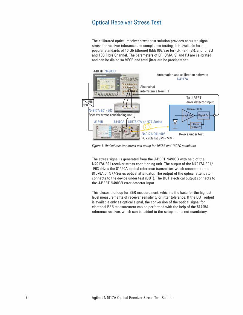
The calibrated optical receiver stress test solution provides accurate signal stress for receiver tolerance and compliance testing. It is available for the popular standards of 10 Gb Ethernet IEEE 802.3ae for -LR, -ER, -SR, and for 8G and 10G Fibre Channel. The parameters of ER, OMA, SI and PJ are calibrated and can be dialed so VECP and total jitter are be precisely set.
Figure 1. Optical receiver stress test setup for 10GbE and 10GFC standards
The stress signal is generated from the J-BERT N4903B with help of the N4917A-E01 receiver stress conditioning unit. The output of the N4917A-E01/ -E03 drives the 81490A optical reference transmitter, which connects to the 81576A or N77-Series optical attenuator. The output of the optical attenuator connects to the device under test (DUT). The DUT electrical output connects to the J-BERT N4903B error detector input.
This closes the loop for BER measurement, which is the base for the highest level measurements of receiver sensitivity or jitter tolerance. If the DUT output is available only as optical signal, the conversion of the optical signal for electrical BER measurement can be performed with the help of the 81495A reference receiver, which can be added to the setup, but is not mandatory.
J-BERT N4903B
8164B 81490A 81576/7A or N77-Series
N4917A-001/003FO cable kit SMF/MMF
Device under test
N4917A-E01/E03Receiver stress conditioning unit
Automation and calibration softwareN4917A
Sinusoidalinterference from P1
To J-BERTerror detector input USB
Receiver (RX)
Amplifier Digital Out
ClockRecovery
E/O Att
GPIB
3Agilent N4917A Optical Receiver Stress Test Solution
Optical Receiver Stress Test
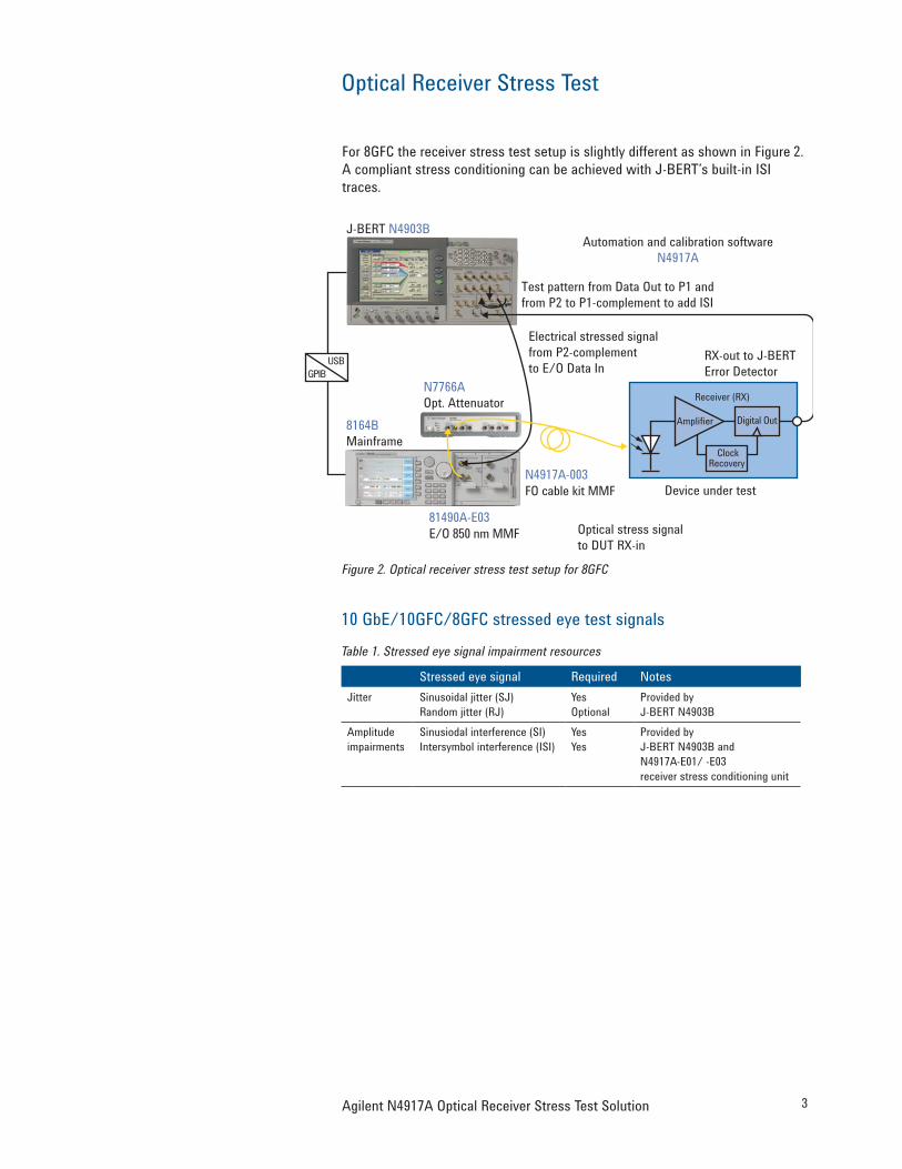
For 8GFC the receiver stress test setup is slightly different as shown in Figure 2. A compliant stress conditioning can be achieved with J-BERT’s built-in ISI traces.
Figure 2. Optical receiver stress test setup for 8GFC
10 GbE/10GFC/8GFC stressed eye test signalsTable 1. Stressed eye signal impairment resources
Stressed eye signal Required NotesJitter Sinusoidal jitter (SJ)
Provided by J-BERT N4903B and N4917A-E01/ -E03 receiver stress conditioning unit
J-BERT N4903B
8164B Mainframe
N7766A Opt. Attenuator
N4917A-003FO cable kit MMF Device under test
81490A-E03E/O 850 nm MMF
Automation and calibration softwareN4917A
Test pattern from Data Out to P1 and from P2 to P1-complement to add ISI
RX-out to J-BERTError Detector
USB
Receiver (RX)
Amplifier Digital Out
ClockRecovery
GPIB
Optical stress signalto DUT RX-in
Electrical stressed signal from P2-complement to E/O Data In
4 Agilent N4917A Optical Receiver Stress Test Solution
User Interface
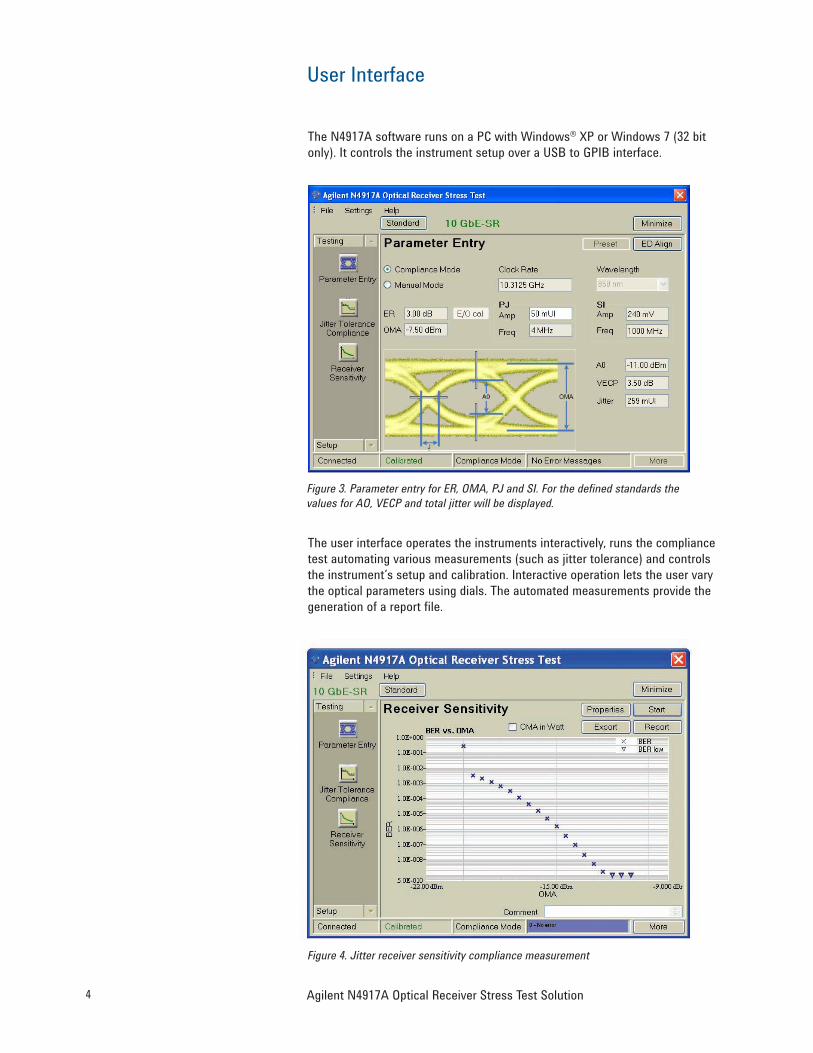
The N4917A software runs on a PC with Windows® XP or Windows 7 (32 bit only). It controls the instrument setup over a USB to GPIB interface.
Figure 3. Parameter entry for ER, OMA, PJ and SI. For the defined standards the values for AO, VECP and total jitter will be displayed.
The user interface operates the instruments interactively, runs the compliance test automating various measurements (such as jitter tolerance) and controls the instrument’s setup and calibration. Interactive operation lets the user vary the optical parameters using dials. The automated measurements provide the generation of a report file.
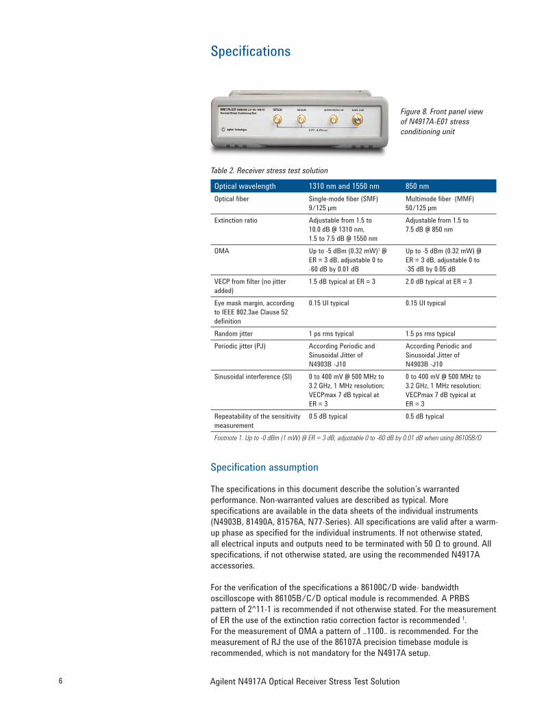
Extinction ratio Adjustable from 1.5 to 10.0 dB @ 1310 nm, 1.5 to 7.5 dB @ 1550 nm
Adjustable from 1.5 to 7.5 dB @ 850 nm
OMA Up to -5 dBm (0.32 mW)1 @ ER = 3 dB, adjustable 0 to -60 dB by 0.01 dB
Up to -5 dBm (0.32 mW) @ ER = 3 dB, adjustable 0 to -35 dB by 0.05 dB
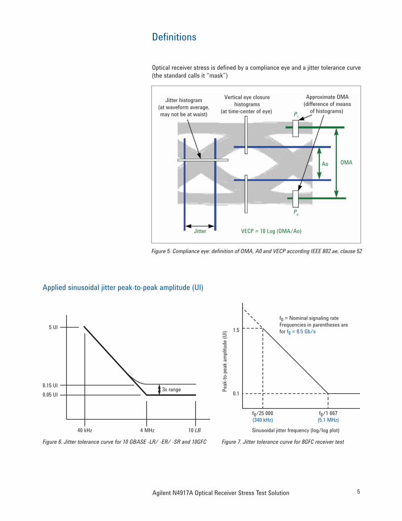
VECP from filter (no jitter added)
1.5 dB typical at ER = 3 2.0 dB typical at ER = 3
Eye mask margin, according to IEEE 802.3ae Clause 52 definition
0.15 UI typical 0.15 UI typical
Random jitter 1 ps rms typical 1.5 ps rms typical Periodic jitter (PJ) According Periodic and
Sinusoidal Jitter of N4903B -J10
According Periodic and Sinusoidal Jitter of N4903B -J10
Sinusoidal interference (SI) 0 to 400 mV @ 500 MHz to 3.2 GHz, 1 MHz resolution; VECPmax 7 dB typical at ER = 3
0 to 400 mV @ 500 MHz to 3.2 GHz, 1 MHz resolution; VECPmax 7 dB typical at ER = 3
Repeatability of the sensitivity measurement
0.5 dB typical 0.5 dB typical
Footnote 1. Up to -0 dBm (1 mW) @ ER = 3 dB, adjustable 0 to -60 dB by 0.01 dB when using 86105B/D
Specification assumption
The specifications in this document describe the solution’s warranted performance. Non-warranted values are described as typical. More specifications are available in the data sheets of the individual instruments (N4903B, 81490A, 81576A, N77-Series). All specifications are valid after a warm-up phase as specified for the individual instruments. If not otherwise stated, all electrical inputs and outputs need to be terminated with 50 Ω to ground. All specifications, if not otherwise stated, are using the recommended N4917A accessories.
For the verification of the specifications a 86100C/D wide- bandwidth oscilloscope with 86105B/C/D optical module is recommended. A PRBS pattern of 2^11-1 is recommended if not otherwise stated. For the measurement of ER the use of the extinction ratio correction factor is recommended 1. For the measurement of OMA a pattern of ..1100.. is recommended. For the measurement of RJ the use of the 86107A precision timebase module is recommended, which is not mandatory for the N4917A setup.
Figure 8. Front panel view of N4917A-E01 stress conditioning unit
7Agilent N4917A Optical Receiver Stress Test Solution
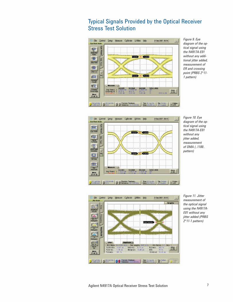
Typical Signals Provided by the Optical Receiver Stress Test Solution
Figure 9. Eye diagram of the op-tical signal using the N4917A-E01 without any addi-tional jitter added, measurement of ER and crossing point (PRBS 2^11-1 pattern)
Figure 10. Eye diagram of the op-tical signal using the N4917A-E01 without any jitter added, measurement of OMA (..1100.. pattern)
Figure 11. Jitter measurement of the optical signal using the N4917A-E01 without any jitter added (PRBS 2^11-1 pattern)
8 Agilent N4917A Optical Receiver Stress Test Solution
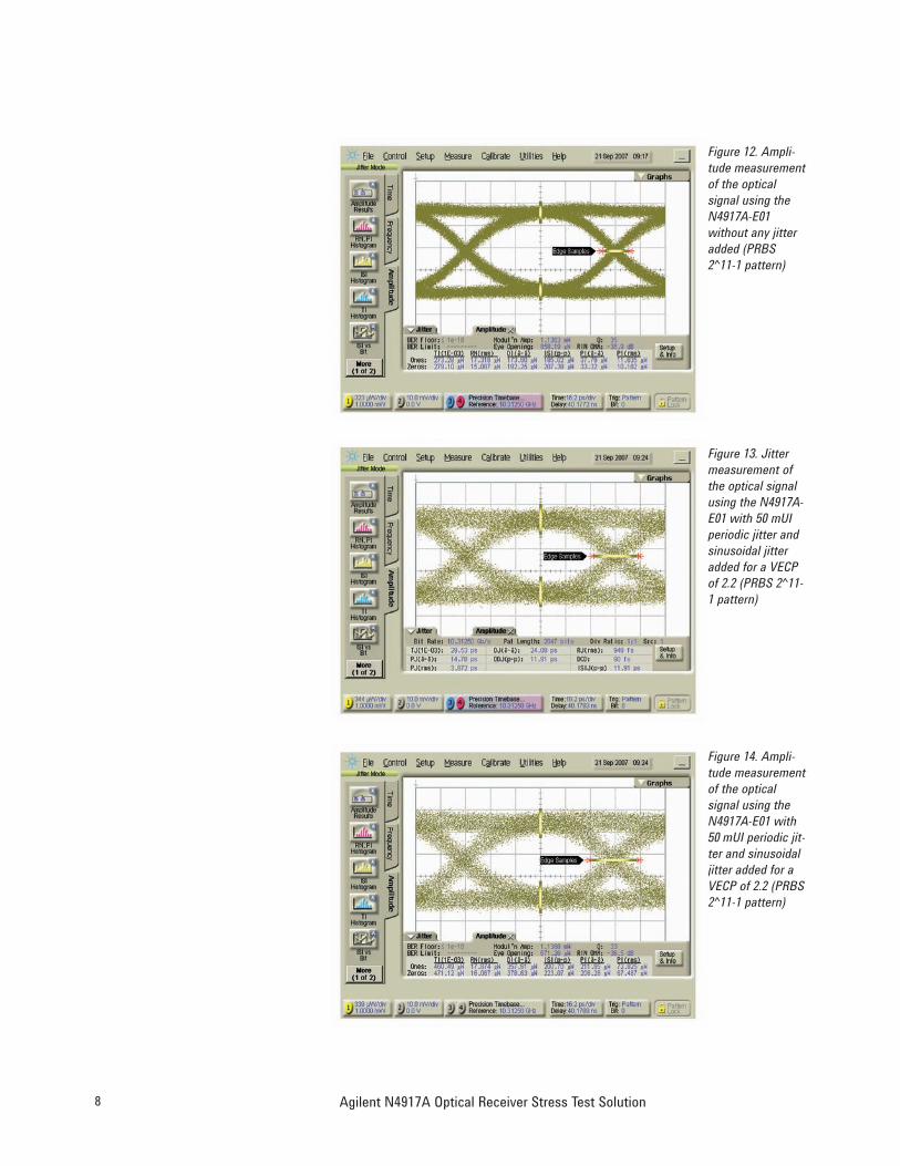
Figure 12. Ampli-tude measurement of the optical signal using the N4917A-E01 without any jitter added (PRBS 2^11-1 pattern)
Figure 13. Jitter measurement of the optical signal using the N4917A-E01 with 50 mUI periodic jitter and sinusoidal jitter added for a VECP of 2.2 (PRBS 2^11-1 pattern)
Figure 14. Ampli-tude measurement of the optical signal using the N4917A-E01 with 50 mUI periodic jit-ter and sinusoidal jitter added for a VECP of 2.2 (PRBS 2^11-1 pattern)
9Agilent N4917A Optical Receiver Stress Test Solution
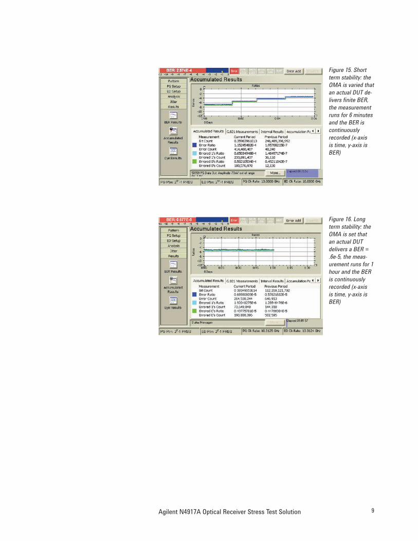
Figure 15. Short term stability: the OMA is varied that an actual DUT de-livers finite BER, the measurement runs for 6 minutes and the BER is continuously recorded (x-axis is time, y-axis is BER)
Figure 16. Long term stability: the OMA is set that an actual DUT delivers a BER = .6e-5, the meas-urement runs for 1 hour and the BER is continuously recorded (x-axis is time, y-axis is BER)
10 Agilent N4917A Optical Receiver Stress Test Solution
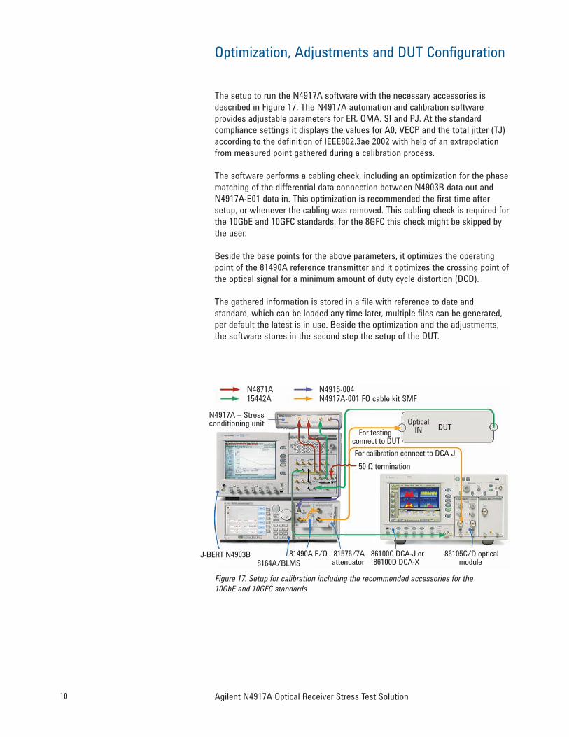
Optimization, Adjustments and DUT Configuration
The setup to run the N4917A software with the necessary accessories is described in Figure 17. The N4917A automation and calibration software provides adjustable parameters for ER, OMA, SI and PJ. At the standard compliance settings it displays the values for A0, VECP and the total jitter (TJ) according to the definition of IEEE802.3ae 2002 with help of an extrapolation from measured point gathered during a calibration process.
The software performs a cabling check, including an optimization for the phase matching of the differential data connection between N4903B data out and N4917A-E01 data in. This optimization is recommended the first time after setup, or whenever the cabling was removed. This cabling check is required for the 10GbE and 10GFC standards, for the 8GFC this check might be skipped by the user.
Beside the base points for the above parameters, it optimizes the operating point of the 81490A reference transmitter and it optimizes the crossing point of the optical signal for a minimum amount of duty cycle distortion (DCD).
The gathered information is stored in a file with reference to date and standard, which can be loaded any time later, multiple files can be generated, per default the latest is in use. Beside the optimization and the adjustments, the software stores in the second step the setup of the DUT.
Figure 17. Setup for calibration including the recommended accessories for the 10GbE and 10GFC standards
N4871A N4915-00415442A
N4917A – Stressconditioning unit
For testing connect to DUTFor calibration connect to DCA-J50 Ω termination
OpticalIN DUT
J-BERT N4903B8164A/BLMS
81576/7Aattenuator
86100C DCA-J or86100D DCA-X
86105C/D opticalmodule
81490A E/O
N4917A-001 FO cable kit SMF
11Agilent N4917A Optical Receiver Stress Test Solution
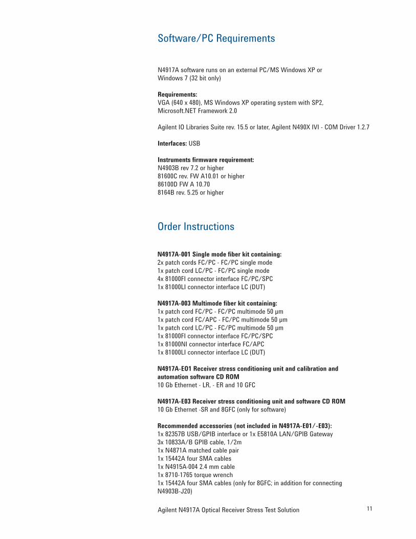
Software/PC Requirements
N4917A software runs on an external PC/MS Windows XP or Windows 7 (32 bit only)
Requirements:VGA (640 x 480), MS Windows XP operating system with SP2, Microsoft.NET Framework 2.0
Agilent IO Libraries Suite rev. 15.5 or later, Agilent N490X IVI - COM Driver 1.2.7
Interfaces: USB
Instruments firmware requirement:N4903B rev 7.2 or higher81600C rev. FW A10.01 or higher86100D FW A 10.708164B rev. 5.25 or higher
N4917A-001 Single mode fiber kit containing:2x patch cords FC/PC - FC/PC single mode1x patch cord LC/PC - FC/PC single mode4x 81000FI connector interface FC/PC/SPC1x 81000LI connector interface LC (DUT)
N4917A-EO1 Receiver stress conditioning unit and calibration and automation software CD ROM10 Gb Ethernet - LR, - ER and 10 GFC
N4917A-E03 Receiver stress conditioning unit and software CD ROM10 Gb Ethernet -SR and 8GFC (only for software)
Recommended accessories (not included in N4917A-E01/-E03):1x 82357B USB/GPIB interface or 1x E5810A LAN/GPIB Gateway3x 10833A/B GPIB cable, 1/2m1x N4871A matched cable pair1x 15442A four SMA cables1x N4915A-004 2.4 mm cable1x 8710-1765 torque wrench1x 15442A four SMA cables (only for 8GFC; in addition for connecting N4903B-J20)
Order Instructions
12 Agilent N4917A Optical Receiver Stress Test Solution
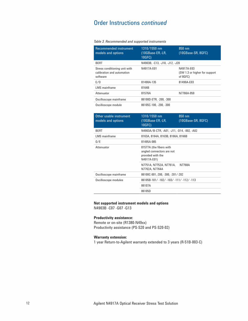
Table 3. Recommended and supported instruments
Recommended instrument models and options
1310/1550 nm (10GBase-ER,-LR, 10GFC)
850 nm (10GBase-SR, 8GFC)
BERT N4903B, -C13, -J10, -J12, -J20 Stress conditioning unit with calibration and automation software
N4917A-E01 N4917A-E03(SW 1.3 or higher for support of 8GFC)
Not supported instrument models and optionsN4903B -C07 -G07 -G13
Productivity assistance:Remote or on-site (R1380-N49xx)Productivity assistance (PS-S20 and PS-S20-02)
Warranty extension:1 year Return-to-Agilent warranty extended to 3 years (R-51B-003-C)
Order Instructions continued
For more information on Agilent Technologies’ products, applications or services, please contact your local Agilent office. The complete list is available at:www.agilent.com/find/contactus
Related Agilent Literature Pub.No.Improving the Accuracy of Optical Transceiver Extinction Ratio Measurements
5989-2602EN
Agilent J-BERT N4903BHigh-Performance Serial BERT with Complete Jitter Tolerance Testing Data Sheet
5990-3217EN
BERT Family Brochure 5988-9514ENAgilent 86100C Wide-Bandwidth Oscilloscope Mainframe and Modules Data Sheet
5989-0278EN
Agilent 86100D DCA-X Wide-Bandwidth Oscilloscope Data Sheet
Agilent Advantage Services is committed to your success throughout your equipment’s lifetime. To keep you competitive, we continually invest in tools and processes that speed up calibration and repair and reduce your cost of ownership. You can also use Infoline Web Services to manage equipment and services more effectively. By sharing our measurement and service expertise, we help you create the products that change our world.
www.agilent.com/quality
www.agilent.com/find/advantageservices
AmericasCanada (877) 894 4414 Brazil (11) 4197 3600Mexico 01800 5064 800 United States (800) 829 4444
Asia PacificAustralia 1 800 629 485China 800 810 0189Hong Kong 800 938 693India 1 800 112 929Japan 0120 (421) 345Korea 080 769 0800Malaysia 1 800 888 848Singapore 1 800 375 8100Taiwan 0800 047 866Other AP Countries (65) 375 8100
www.agilent.com/find/emailupdatesGet the latest information on the products and applications you select.
www.lxistandard.orgLAN eXtensions for Instruments puts the power of Ethernet and the Web inside your test systems. Agilent is a founding member of the LXI consortium.
Agilent Channel Partnerswww.agilent.com/find/channelpartnersGet the best of both worlds: Agilent’s measurement expertise and product breadth, combined with channel partner convenience.
Windows and MS Windows are U.S. registered trademarks of Microsoft Corporation.
Quality Management SystemQuality Management SysISO 9001:2008Agilent Electronic Measurement Group