Page 1 of 23 Salah, et al, Aging Effects Evaluation Of A Decommissioned Boeing CFRP 737-200 Horizontal Stabilizer (Phase II) AGING EFFECTS EVALUATION OF A DECOMMISSIONED BOEING CFRP 737-200 HORIZONTAL STABILIZER (Phase II) Lamia Salah and John Tomblin National Institute for Aviation Research, Wichita, KS Curtis Davies FAA William J. Hughes Technical Center, Atlantic City International Airport, NJ Abstract Most of the aging aircraft studies conducted so far have focused on metallic structures; however, as more composite components are certified and used on primary and secondary aircraft structures, it is crucial to address aging of composite structures as well. With these concerns in mind, the primary objective of this paper is to evaluate the aging effects, environmental and loading, on a composite stabilizer after 18 years of service. A prototype Boeing 737-200 graphite/epoxy stabilizer built as part of the NASA Aircraft Energy Efficiency (ACEE) program initiated in July 1977 is the subject of this investigation. The purpose of the prototype program was to challenge aircraft manufacturers to redesign existing aircraft components using lighter graphite/epoxy composites to reduce structural weight for fuel efficiency. Boeing manufactured and certified five shipsets in August 1982. These structures achieved 21.6% weight savings compared to their metal counterparts. Three shipsets have been retired and two are still in local service with a United States airline. This paper summarizes the ACEE program, the current investigative plan, details of the teardown activity, and results of the nondestructive inspection (NDI) as well as the destructive physical and thermal tests results obtained to date. A nondestructive evaluation in accordance with the recommended field methods verified the current damage state of the retired stabilizer. Additional sophisticated NDI techniques, such as 3-D photogrammetry, were also used to characterize the damage state. Destructive evaluation, using the same test methods as used to certify the stabilizer, will be used to establish the end of service life capabilities of the structure. Current NDI, mechanical, and physical test methods are compared with those used in the development program to assess differences attributable to the state of the art between 1982 and today. The ultimate goal is to understand the aging mechanisms, characterize their effects on the composite structure, and to give recommendations pertaining to characterizing composite aging. This will provide design and certification guidelines regarding the capability of aging composites.
Transcript
Page 1 of 23 Salah, et al, Aging Effects Evaluation Of A Decommissioned Boeing CFRP 737-200 Horizontal Stabilizer (Phase II)
AGING EFFECTS EVALUATION OF A DECOMMISSIONED BOEING CFRP 737-200 HORIZONTAL STABILIZER (Phase II)
Lamia Salah and John Tomblin National Institute for Aviation Research, Wichita, KS
Curtis Davies
FAA William J. Hughes Technical Center, Atlantic City International Airport, NJ
Abstract Most of the aging aircraft studies conducted so far have focused on metallic structures; however, as more composite components are certified and used on primary and secondary aircraft structures, it is crucial to address aging of composite structures as well. With these concerns in mind, the primary objective of this paper is to evaluate the aging effects, environmental and loading, on a composite stabilizer after 18 years of service. A prototype Boeing 737-200 graphite/epoxy stabilizer built as part of the NASA Aircraft Energy Efficiency (ACEE) program initiated in July 1977 is the subject of this investigation. The purpose of the prototype program was to challenge aircraft manufacturers to redesign existing aircraft components using lighter graphite/epoxy composites to reduce structural weight for fuel efficiency. Boeing manufactured and certified five shipsets in August 1982. These structures achieved 21.6% weight savings compared to their metal counterparts. Three shipsets have been retired and two are still in local service with a United States airline. This paper summarizes the ACEE program, the current investigative plan, details of the teardown activity, and results of the nondestructive inspection (NDI) as well as the destructive physical and thermal tests results obtained to date. A nondestructive evaluation in accordance with the recommended field methods verified the current damage state of the retired stabilizer. Additional sophisticated NDI techniques, such as 3-D photogrammetry, were also used to characterize the damage state. Destructive evaluation, using the same test methods as used to certify the stabilizer, will be used to establish the end of service life capabilities of the structure. Current NDI, mechanical, and physical test methods are compared with those used in the development program to assess differences attributable to the state of the art between 1982 and today. The ultimate goal is to understand the aging mechanisms, characterize their effects on the composite structure, and to give recommendations pertaining to characterizing composite aging. This will provide design and certification guidelines regarding the capability of aging composites.
Page 2 of 23 Salah, et al, Aging Effects Evaluation Of A Decommissioned Boeing CFRP 737-200 Horizontal Stabilizer (Phase II)
Introduction As more commercial and military airplanes are being used beyond their design life, it becomes necessary to answer the question of their continued airworthiness and structural integrity. Most of the aging aircraft studies conducted so far have focused on metallic structures; however, with the increasing use of composites in primary aircraft structures, it is crucial to address the aging effects for composite components. As an attempt to understand the aging effects on composite structures, the National Institute for Aviation Research (NIAR) is evaluating the structural health of a decommissioned B-737 graphite epoxy horizontal stabilizer after 18 years of service. The composite stabilizer is being evaluated using both NDI methods prior to teardown and a destructive evaluation after teardown. Data generated will be used to understand the aging mechanisms of composite structures currently in service, to evaluate the efficiency of field NDI methods to detect flaws, and to substantiate the original design and repair philosophies. NDI methods conducted on the stabilizer prior to teardown were performed at the Sandia National Laboratories and at the Boeing Company and included thermography, RapidScan, Laser UT, and pulse-echo ultrasonics. This work was reported in the Phase I presentation at the 2005 Aging Aircraft Conference [1, 2]. The photogrammetry system was also used by the NIAR as an NDI method to inspect areas of known defects in the part prior to its disassembly. The purpose was to compare the accuracy of the different field inspection methods in detecting flaws induced during either manufacture or service including delaminations, disbonds, impact damage, moisture ingression, corrosion of the aluminum lightning protection scheme, etc. This is essential to ensure the safety and airworthiness of a composite aircraft structure. A teardown of the stabilizer was conducted following the reverse of the structure’s original assembly sequence. The structure was then inspected both visually and using ultrasonic methods (through-transmission and pulse-echo). Results were compared to those obtained prior to the structure’s disassembly and a destructive evaluation was conducted to confirm the condition of the stabilizer. The destructive evaluation included thermal testing, image analysis, physical testing, and mechanical testing. Thermal Analysis used both dynamic mechanical analysis (DMA) and differential scanning calorimetry (DSC) to determine the aged material’s glass transition temperature and its degree of cure. Image Analysis was also performed to detect defects in the structure induced either during manufacture or service. Physical tests were performed to quantify the porosity levels identified by the different NDI methods and to correlate the aged material’s mechanical performance with its original mechanical capability. The ultimate goal is to understand the aging mechanism on the structure and to identify possible changes in the material properties with respect to its original design requirements
ACEE Program Overview The B-737-200 graphite/epoxy horizontal stabilizer used for this investigation was developed by Boeing as part of the NASA ACEE program. NASA initiated the comprehensive ACEE program in late 1975 with the purpose of developing new technologies to reduce fuel consumption in commercial transport aircraft. The ACEE program was subdivided into four development areas: laminar flow systems, advanced aerodynamics, flight controls, and composite structures [3], with the goal of yielding a 40% reduction in fuel consumption. The ACEE Composites program focused on achieving fuel efficiency through the use of lighter materials in existing aircraft structural components. Composite materials provide significant weight reductions thus decreasing drag for a given payload translating into lower energy consumption and direct operating cost.
Page 3 of 23 Salah, et al, Aging Effects Evaluation Of A Decommissioned Boeing CFRP 737-200 Horizontal Stabilizer (Phase II)
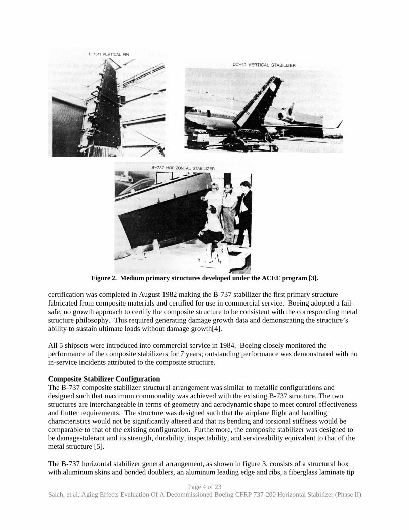
A building block approach was selected where composite structure development would start with lightly loaded secondary components followed by medium primary components and finally conclude with wing and fuselage development. Important intermediate developmental milestones were established in case the ACEE program was ended before the complete implementation of composites in wing and fuselage structures. The ACEE Composites program targeted six aircraft secondary and medium primary components as shown in figures 1 and 2: The upper aft rudder of the Douglas DC-10, the inboard ailerons of the Lockheed L-1011, and the elevators of the Boeing 727 were the selected secondary structures (figure 1). The vertical stabilizers of the Lockheed L-1011 and Douglas DC-10, and the horizontal stabilizer of the Boeing 737 were the selected medium primary structures (figure 2).
Figure 1. Secondary aircraft structures developed under the ACEE program [3].
The ACEE B-737 Composite Stabilizer Program targeted the following objectives:
• Achieve at least a 20% weight reduction with respect to the existing metal structure • Manufacture at least 40% (by weight) of the components from composite materials • Demonstrate cost competitiveness of the structure • Obtain FAA certification for the structure and to evaluate the structure in service
As part of the ACEE program, Boeing redesigned and manufactured 5½ shipsets of their 737-200 horizontal stabilizer using graphite-epoxy composites. The B-737 horizontal stabilizer program was initiated in July 1977, certification test requirements were completed by February 1982, and
Page 4 of 23 Salah, et al, Aging Effects Evaluation Of A Decommissioned Boeing CFRP 737-200 Horizontal Stabilizer (Phase II)
Figure 2. Medium primary structures developed under the ACEE program [3].
certification was completed in August 1982 making the B-737 stabilizer the first primary structure fabricated from composite materials and certified for use in commercial service. Boeing adopted a fail-safe, no growth approach to certify the composite structure to be consistent with the corresponding metal structure philosophy. This required generating damage growth data and demonstrating the structure’s ability to sustain ultimate loads without damage growth[4]. All 5 shipsets were introduced into commercial service in 1984. Boeing closely monitored the performance of the composite stabilizers for 7 years; outstanding performance was demonstrated with no in-service incidents attributed to the composite structure.
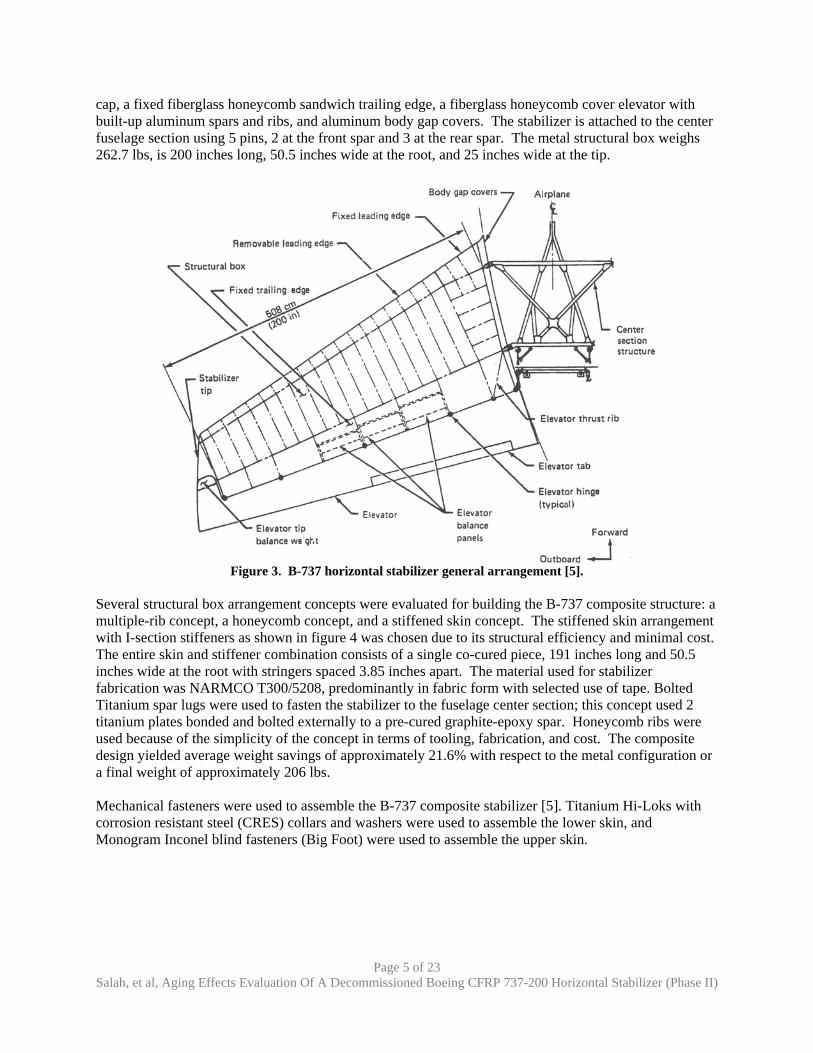
Composite Stabilizer Configuration The B-737 composite stabilizer structural arrangement was similar to metallic configurations and designed such that maximum commonality was achieved with the existing B-737 structure. The two structures are interchangeable in terms of geometry and aerodynamic shape to meet control effectiveness and flutter requirements. The structure was designed such that the airplane flight and handling characteristics would not be significantly altered and that its bending and torsional stiffness would be comparable to that of the existing configuration. Furthermore, the composite stabilizer was designed to be damage-tolerant and its strength, durability, inspectability, and serviceability equivalent to that of the metal structure [5]. The B-737 horizontal stabilizer general arrangement, as shown in figure 3, consists of a structural box with aluminum skins and bonded doublers, an aluminum leading edge and ribs, a fiberglass laminate tip
Page 5 of 23 Salah, et al, Aging Effects Evaluation Of A Decommissioned Boeing CFRP 737-200 Horizontal Stabilizer (Phase II)
cap, a fixed fiberglass honeycomb sandwich trailing edge, a fiberglass honeycomb cover elevator with built-up aluminum spars and ribs, and aluminum body gap covers. The stabilizer is attached to the center fuselage section using 5 pins, 2 at the front spar and 3 at the rear spar. The metal structural box weighs 262.7 lbs, is 200 inches long, 50.5 inches wide at the root, and 25 inches wide at the tip.
Figure 3. B-737 horizontal stabilizer general arrangement [5].
Several structural box arrangement concepts were evaluated for building the B-737 composite structure: a multiple-rib concept, a honeycomb concept, and a stiffened skin concept. The stiffened skin arrangement with I-section stiffeners as shown in figure 4 was chosen due to its structural efficiency and minimal cost. The entire skin and stiffener combination consists of a single co-cured piece, 191 inches long and 50.5 inches wide at the root with stringers spaced 3.85 inches apart. The material used for stabilizer fabrication was NARMCO T300/5208, predominantly in fabric form with selected use of tape. Bolted Titanium spar lugs were used to fasten the stabilizer to the fuselage center section; this concept used 2 titanium plates bonded and bolted externally to a pre-cured graphite-epoxy spar. Honeycomb ribs were used because of the simplicity of the concept in terms of tooling, fabrication, and cost. The composite design yielded average weight savings of approximately 21.6% with respect to the metal configuration or a final weight of approximately 206 lbs. Mechanical fasteners were used to assemble the B-737 composite stabilizer [5]. Titanium Hi-Loks with corrosion resistant steel (CRES) collars and washers were used to assemble the lower skin, and Monogram Inconel blind fasteners (Big Foot) were used to assemble the upper skin.
Page 6 of 23 Salah, et al, Aging Effects Evaluation Of A Decommissioned Boeing CFRP 737-200 Horizontal Stabilizer (Phase II)
Figure 4. B-737 composite structural arrangement.
Corrosion Protection Scheme The corrosion system, as shown in figure 5, was designed to isolate the graphite-epoxy surfaces from the aluminum structure thus minimizing galvanic corrosion. Corrosion protection was achieved by covering all graphite-epoxy surfaces mating to the aluminum structure with either a fiberglass ply co-cured with the graphite-epoxy or by painting the surface with a primer and epoxy enamel. All aluminum structure was anodized or alodine treated, primed, and enameled. Fasteners were installed with wet polysulfide sealant.
Figure 5. Corrosion protection system.
Page 7 of 23 Salah, et al, Aging Effects Evaluation Of A Decommissioned Boeing CFRP 737-200 Horizontal Stabilizer (Phase II)
Lightning Protection System An electrical path was provided around the entire perimeter of the structural box by means of bonding straps connecting the aluminum leading edge, the aluminum rib cap of the outboard closure rib, and the aluminum elevator spar. An Aluminum flame spray was used to protect the stabilizer’s critical strike area in the event of a lightning strike. The flame spray was applied on the outboard 18 inches of the upper and lower skins. The outboard skin panels were insulated using a layer of fiberglass co-cured to the parent structure prior to the application of the conductive coating [5].
Composite B-737 Horizontal Stabilizer Fleet Status Table 1 summarizes the status of the 5 composite stabilizers sets as of October 2004. Shipsets 3, 4, and 5 were retired after 19300, 55000 and 48000 flights respectively. Shipsets 1 and 2 are still in service with over 43000 accumulated flights each. Airlines are identified only as a letter designation due to information release requirements.
Table 1. B-737 fleet status as of October 31, 2004 Shipset / Production Line No.
Entry into Service Airline Status as of October 31, 2004
1/ 1003 2 May 1984 A In-service (58000 hours, 43000 flights) 2/ 1012 21 March 1984 A In-service (58000 hours, 44000 flights) 3/ 1025 11 May 1984 B Aircraft damaged beyond economical repair in
1990; partial teardown of stabilizer completed in 1991 (17300 hours, 19300 flights)
4/ 1036 17 July 1984 B & C Stabilizers removed from service in 2002 (approximately 39000 hours, 55000 flights); partial teardown of right-hand stabilizer unit at Boeing
5/ 1042 14 August 1984 B & D Stabilizers removed from service in 2002 (approximately 52000 hours, 48000 flights); teardown of left-hand stabilizer unit at Boeing; teardown of right-hand stabilizer unit at NIAR/Wichita State University
Teardown Objective The objective of the teardown of the right-hand side of the B-737 composite stabilizer is to evaluate the aging effects on the composite structure after 18 years of service. A picture of the right-hand stabilizer as delivered to the NIAR is shown in figure 6. The methodology is as follows:
• Conduct a thorough NDI to identify flaws induced during service prior to and after teardown
• Conduct physical and thermal tests to identify possible changes in the chemical composition of the material
• Conduct coupon level static and fatigue testing to investigate any degradation in the mechanical properties of the material
Page 8 of 23 Salah, et al, Aging Effects Evaluation Of A Decommissioned Boeing CFRP 737-200 Horizontal Stabilizer (Phase II)
Figure 6. Right-hand B-737 composite stabilizer after 18 years of service.
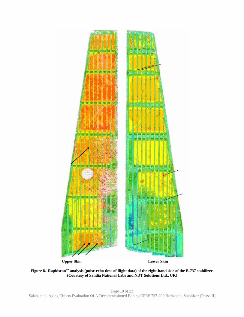
Nondestructive Evaluation Prior to Teardown Nondestructive evaluation was performed on the right-hand side of the stabilizer by the Boeing Company using pulse-echo at a frequency of 3.5 MHz as shown in figure 7. The pulse-echo scans shows a very porous upper skin compared to the lower skin. The upper skin scan also shows a repair implemented between rib stations 2 and 3 and stringers 5 and 8 (stringer 1 being the closest to the rear spar). Figure 8 illustrates the non-destructive inspection results obtained using RapidScan (Courtesy Sandia National Laboratories) and, similar to the Boeing scan, shows large amounts of porosity in the upper skin and several stringers disbonds (illustrated using the arrows). The results of the Phase I program [1] will be used in the evaluation of mechanical and physical tests performed during Phase II.
Page 9 of 23 Salah, et al, Aging Effects Evaluation Of A Decommissioned Boeing CFRP 737-200 Horizontal Stabilizer (Phase II)
Upper Skin Lower Skin
Figure 7. Pulse-echo amplitude scan of the right-hand side of the B-737 stabilizer performed at 3.5 MHz. (Courtesy The Boeing Company)
Page 10 of 23 Salah, et al, Aging Effects Evaluation Of A Decommissioned Boeing CFRP 737-200 Horizontal Stabilizer (Phase II)
Upper Skin Lower Skin
Figure 8. Rapidscantm analysis (pulse-echo time of flight data) of the right-hand side of the B-737 stabilizer. (Courtesy of Sandia National Labs and NDT Solutions Ltd., UK)
Page 11 of 23 Salah, et al, Aging Effects Evaluation Of A Decommissioned Boeing CFRP 737-200 Horizontal Stabilizer (Phase II)
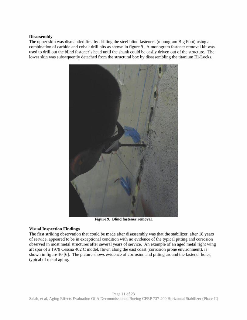
Disassembly The upper skin was dismantled first by drilling the steel blind fasteners (monogram Big Foot) using a combination of carbide and cobalt drill bits as shown in figure 9. A monogram fastener removal kit was used to drill out the blind fastener’s head until the shank could be easily driven out of the structure. The lower skin was subsequently detached from the structural box by disassembling the titanium Hi-Locks.
Figure 9. Blind fastener removal.
Visual Inspection Findings The first striking observation that could be made after disassembly was that the stabilizer, after 18 years of service, appeared to be in exceptional condition with no evidence of the typical pitting and corrosion observed in most metal structures after several years of service. An example of an aged metal right wing aft spar of a 1979 Cessna 402 C model, flown along the east coast (corrosion prone environment), is shown in figure 10 [6]. The picture shows evidence of corrosion and pitting around the fastener holes, typical of metal aging.
Page 12 of 23 Salah, et al, Aging Effects Evaluation Of A Decommissioned Boeing CFRP 737-200 Horizontal Stabilizer (Phase II)
Figure 10. Corroded right-wing aft spar of a 1979 Cessna 402C model aircraft.
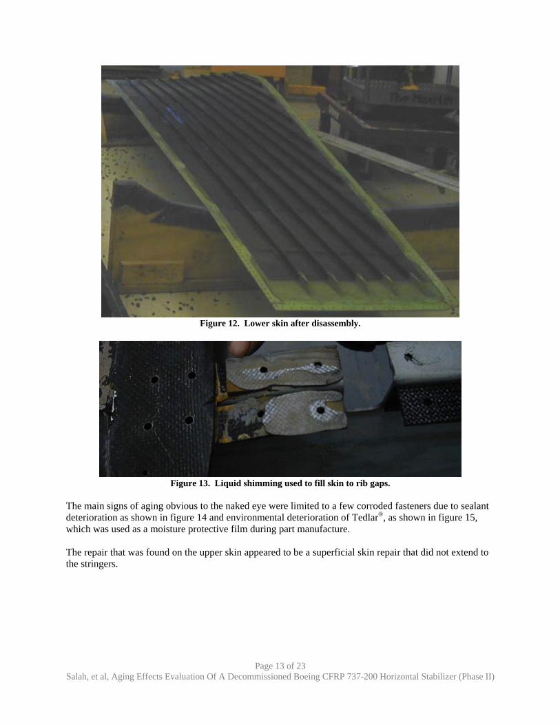
Compared to the left-hand stabilizer, minor residual strains were recorded on both the upper and lower skins as shown in figures 11 and 12, removed fasteners seemed in good condition with no evidence of corrosion, and a minimal amount of shims, as shown in figure 13, were used on the right-hand side of the stabilizer.
Figure 11. Upper skin after disassembly.
Page 13 of 23 Salah, et al, Aging Effects Evaluation Of A Decommissioned Boeing CFRP 737-200 Horizontal Stabilizer (Phase II)
Figure 12. Lower skin after disassembly.
Figure 13. Liquid shimming used to fill skin to rib gaps.
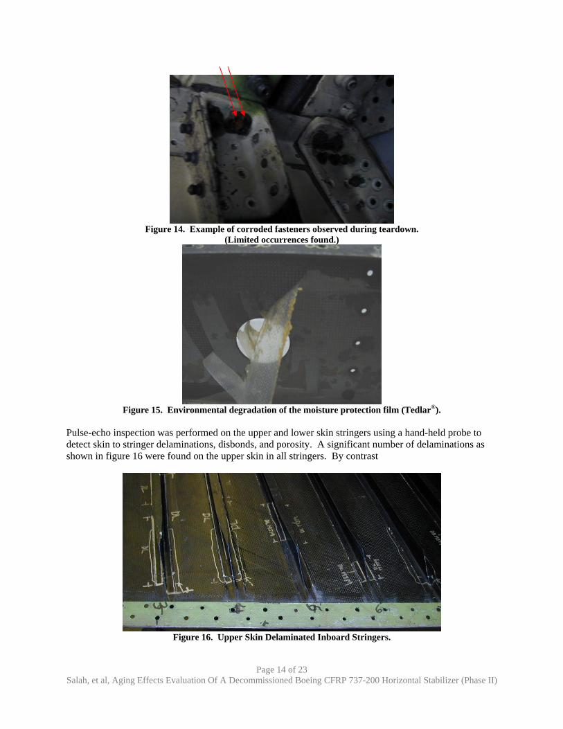
The main signs of aging obvious to the naked eye were limited to a few corroded fasteners due to sealant deterioration as shown in figure 14 and environmental deterioration of Tedlar®, as shown in figure 15, which was used as a moisture protective film during part manufacture. The repair that was found on the upper skin appeared to be a superficial skin repair that did not extend to the stringers.
Page 14 of 23 Salah, et al, Aging Effects Evaluation Of A Decommissioned Boeing CFRP 737-200 Horizontal Stabilizer (Phase II)
Figure 14. Example of corroded fasteners observed during teardown.
(Limited occurrences found.)
Figure 15. Environmental degradation of the moisture protection film (Tedlar®).
Pulse-echo inspection was performed on the upper and lower skin stringers using a hand-held probe to detect skin to stringer delaminations, disbonds, and porosity. A significant number of delaminations as shown in figure 16 were found on the upper skin in all stringers. By contrast
Page 15 of 23 Salah, et al, Aging Effects Evaluation Of A Decommissioned Boeing CFRP 737-200 Horizontal Stabilizer (Phase II)
few disbonds were detected in the lower skin (stringers 1, 2, 3, 5, 6 and 8). No major defects were detected in the stringer webs in the lower skin. Porosity and a few delaminations were recorded in the upper skin stringer web numbers 5, 8 and 9. Through-transmission and pulse-echo were subsequently used to inspect the unsupported areas of the skin and are reported in the next section.
Nondestructive Evaluation after Teardown Pulse-echo and through-transmission nondestructive methods were used to inspect the stabilizer using 2.25 MHz frequency transducers. Both methods confirmed the large amounts of porosity in the upper skin as was found in the Boeing and Sandia National Lab scans. Pulse-echo results obtained at NIAR confirmed the existence of the delaminated stringers and demonstrated the increased accuracy and sensitivity of the current inspection methods compared to those used in the 1980s as shown in figure 17
1980 2005
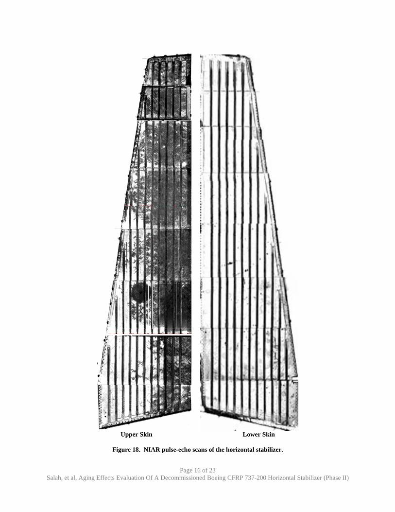
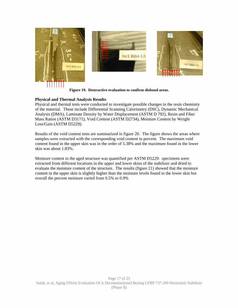
Figure 17. Ultrasonic inspection sensitivity of the 1980s versus today’s equipment capabilities. Similar to the Boeing scans, NDI pulse-echo scans conducted at NIAR, figure 18, showed significant levels of porosity in the upper skin compared to the lower skin. This difference in porosity was probably induced by tooling and process variability during the manufacturing process. Porosity levels were quantified using image analysis and physical tests. Destructive evaluation, as shown in figure 19, was conducted on sections of the stabilizer identified as containing disbonds from the NDI inspection to verify the existence of these delaminations. Destructive evaluation confirmed the NDI results.
Page 16 of 23 Salah, et al, Aging Effects Evaluation Of A Decommissioned Boeing CFRP 737-200 Horizontal Stabilizer (Phase II)
Upper Skin Lower Skin
Figure 18. NIAR pulse-echo scans of the horizontal stabilizer.
Page 17 of 23 Salah, et al, Aging Effects Evaluation Of A Decommissioned Boeing CFRP 737-200 Horizontal Stabilizer
(Phase II)
Figure 19. Destructive evaluation to confirm disbond areas.
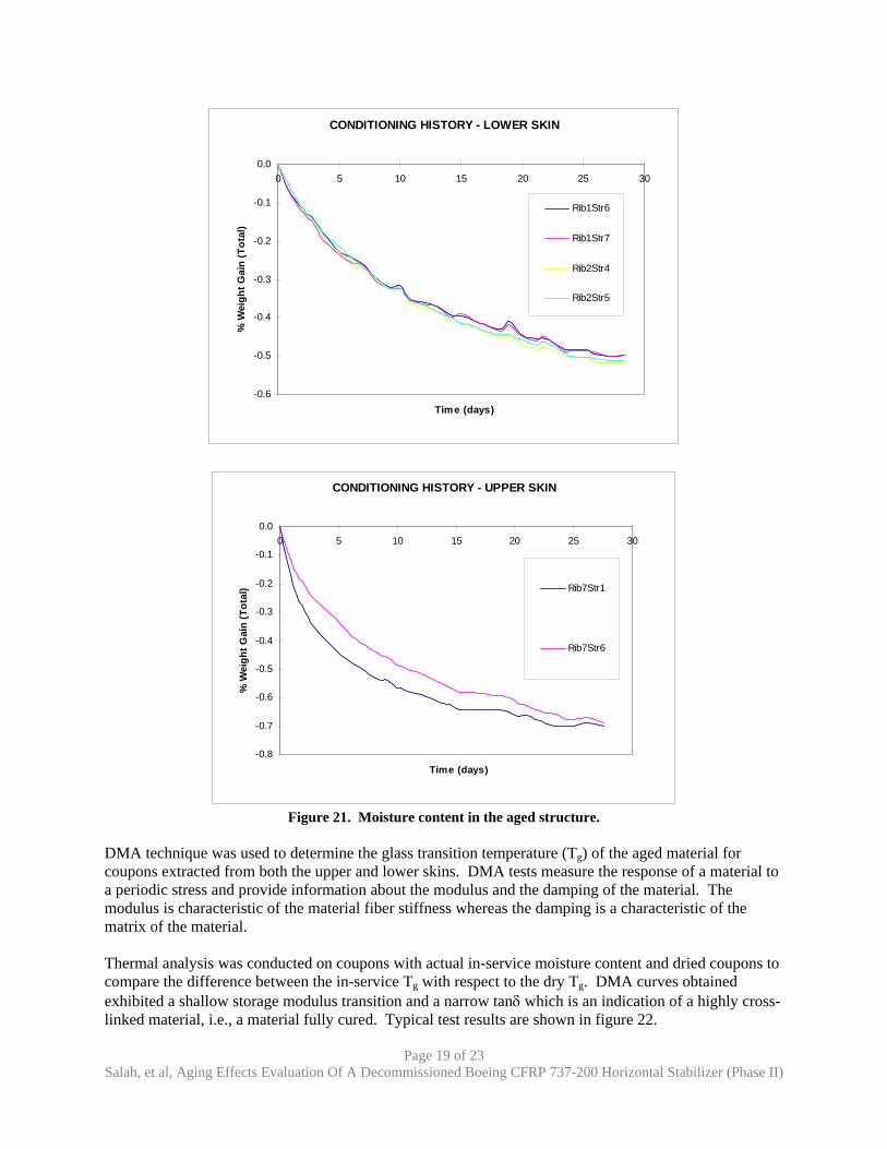
Physical and Thermal Analysis Results Physical and thermal tests were conducted to investigate possible changes in the resin chemistry of the material. These include Differential Scanning Calorimetry (DSC), Dynamic Mechanical Analysis (DMA), Laminate Density by Water Displacement (ASTM D 792), Resin and Fiber Mass Ratios (ASTM D3171), Void Content (ASTM D2734), Moisture Content by Weight Loss/Gain (ASTM D5229). Results of the void content tests are summarized in figure 20. The figure shows the areas where samples were extracted with the corresponding void content in percent. The maximum void content found in the upper skin was in the order of 5.38% and the maximum found in the lower skin was about 1.83%. Moisture content in the aged structure was quantified per ASTM D5229: specimens were extracted from different locations in the upper and lower skins of the stabilizer and dried to evaluate the moisture content of the structure. The results (figure 21) showed that the moisture content in the upper skin is slightly higher than the moisture levels found in the lower skin but overall the percent moisture varied from 0.5% to 0.9%
Page 18 of 23 Salah, et al, Aging Effects Evaluation Of A Decommissioned Boeing CFRP 737-200 Horizontal Stabilizer
(Phase II)
Upper Skin Lower Skin
Figure 20. Void content summary.
Page 19 of 23 Salah, et al, Aging Effects Evaluation Of A Decommissioned Boeing CFRP 737-200 Horizontal Stabilizer (Phase II)
CONDITIONING HISTORY - LOWER SKIN
-0.6
-0.5
-0.4
-0.3
-0.2
-0.1
0.00 5 10 15 20 25 30
Time (days)
% W
eigh
t Gai
n (T
otal
)
Rib1Str6
Rib1Str7
Rib2Str4
Rib2Str5
CONDITIONING HISTORY - UPPER SKIN
-0.8
-0.7
-0.6
-0.5
-0.4
-0.3
-0.2
-0.1
0.00 5 10 15 20 25 30
Time (days)
% W
eigh
t Gai
n (T
otal
) Rib7Str1
Rib7Str6
Figure 21. Moisture content in the aged structure.
DMA technique was used to determine the glass transition temperature (Tg) of the aged material for coupons extracted from both the upper and lower skins. DMA tests measure the response of a material to a periodic stress and provide information about the modulus and the damping of the material. The modulus is characteristic of the material fiber stiffness whereas the damping is a characteristic of the matrix of the material. Thermal analysis was conducted on coupons with actual in-service moisture content and dried coupons to compare the difference between the in-service Tg with respect to the dry Tg. DMA curves obtained exhibited a shallow storage modulus transition and a narrow tanδ which is an indication of a highly cross-linked material, i.e., a material fully cured. Typical test results are shown in figure 22.
Page 20 of 23 Salah, et al, Aging Effects Evaluation Of A Decommissioned Boeing CFRP 737-200 Horizontal Stabilizer (Phase II)
(a) As extracted material.
(b) Dry material.
Figure 22. Typical DMA results for as extracted and dry material. Figure 22(a) shows the DMA results of the as extracted material whereas figure 22(b) shows results for the dry material. The glass transition temperatures obtained from the storage modulus and the tanδ curves of the as extracted material were 176.79°C and 197.64°C respectively. The corresponding values for the dry material were 208.24°C and 226.52°C.
Page 21 of 23 Salah, et al, Aging Effects Evaluation Of A Decommissioned Boeing CFRP 737-200 Horizontal Stabilizer (Phase II)
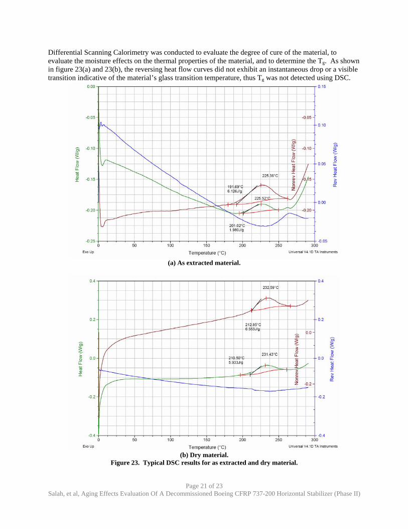
Differential Scanning Calorimetry was conducted to evaluate the degree of cure of the material, to evaluate the moisture effects on the thermal properties of the material, and to determine the Tg. As shown in figure 23(a) and 23(b), the reversing heat flow curves did not exhibit an instantaneous drop or a visible transition indicative of the material’s glass transition temperature, thus Tg was not detected using DSC.
(a) As extracted material.
(b) Dry material.
Figure 23. Typical DSC results for as extracted and dry material.
Page 22 of 23 Salah, et al, Aging Effects Evaluation Of A Decommissioned Boeing CFRP 737-200 Horizontal Stabilizer (Phase II)
Furthermore, the broadness of the signal is an indication that the material is highly cross-linked and thus supports the results obtained using DMA. The reversing heat flow curves shown in figure 23 characterize the chemical reactions occurring as the material is heated up which relates to the cure temperature of the material. Furthermore for both as extracted and dry materials, the DSC heat of reaction values were not significant indicating that the material was fully cured and highly cross-linked. Drying the specimen increased the cure onset as shown in figure 23b. However, water content did not affect the degree of cure as the DSC heat of reaction values remained extremely small (<6J/g) indicating a highly cross-linked material (fully cured).
Image Analysis Image analysis was conducted to inspect the structure for voids, microcracks, and any other evidence of aging. Samples were extracted from various locations in the structure, potted, polished, and viewed under the microscope for possible signs of aging. Figure 24 shows a cross section of upper skin stringer 2 at rib station 2 at a magnification of 50x. Both images show evidence of porosity throughout the laminate. The flange cross section also shows evidence of microcracking initiating in the void areas.
Stringer web flange
Figure 24. Cross section of stringer 2 at rib station 2 at a magnification of 50x.
Ongoing Efforts Coupon and element mechanical tests are planned to investigate any possible changes in the mechanical properties. All coupons will be heavily instrumented to characterize material deformation and possible strain gradients. Tests will include: static tension, static compression, stringer T pull-off testing to assess the strength of skin-to-stringer co-cured bond, rail shear tests, and lap shear tests. Fatigue on skin coupons will also be conducted at strain levels representative of in-service strains to assess the residual fatigue life of the structure. A limited number of element tests will be conducted including spar chord crippling tests and three-stringer stiffened panel tests to investigate skin panel to stiffener attachment static and fatigue strength under compression. All mechanical data generated as part of this study will be compared to the baseline mechanical data generated for the stabilizer certification. Testing of current T300/5208 material will also be conducted to evaluate the changes between the raw material 25 years ago and the current raw material to establish a baseline for any further testing which
Page 23 of 23 Salah, et al, Aging Effects Evaluation Of A Decommissioned Boeing CFRP 737-200 Horizontal Stabilizer (Phase II)
may be done with today’s material. A limited test matrix including static tension, static compression, rail shear, and interlaminar shear will be conducted for this comparison.
Conclusions Thus far, the teardown of the B-737 stabilizer revealed a composite structure that held up well in-service. It did not exhibit any obvious signs of aging such as pitting and corrosion as would a metal structure with a similar service history. From the extensive NDI evaluations a number of items were found: (1) NDI improvements make detection of more defects possible, (2) although the NDI performed 20 years ago was less effective, it established an acceptable level of structural integrity for the unit being investigated, and (3) current NDI methods will provide additional safety margins provided similar design philosophies are used. The physical and thermal tests show that even after 20 years, moisture levels were as predicted during the design phase. The resin system maintained its thermal resistance as the Tg had not degraded from that reported in the certification program. The resin also demonstrated a high degree of cross-linking indicating a fully cured part. The image analysis confirmed the NDI findings. Areas indicated as having high porosity were found to have numerous small pockets in the resin matrix. The disassembly found the delaminations detected by the NDI methods. The disassembly found they were mostly on the upper surface leading to the conclusion that they were service induced, likely from overloads during maintenance, This teardown also provides closure to the very successful NASA ACEE program undertaken almost 30 years ago and affirms the viability of composite materials as substitutes for metals. The NASA ACEE program has demonstrated many proposed degradation mechanisms of composite materials do not affect the structure, as theorized. The composite materials used today verses 25 years ago have undergone many durability improvements and are even better able to handle environmental and aging attacks. The mechanical evaluation will provide additional evidence of composite materials capabilities over the expected service life of commercial aircraft structures. References [1] L. Salah, J. Tomblin, C. Davies, M. Miller and J. Kollgaard, January 2005, “Aging Effects
Evaluation of a Decommissioned Boeing CFRP 737-200 Horizontal Stabilizer”, 8th Joint FAA/DoD/NASA Aging Aircraft Conference.
[2] D. Hoffman, J. Kollgaard, and M. Miller, January 2005, “Structural Teardown Inspection of an Advanced Composite Stabilizer for Boeing 737 Aircraft”, 8th Joint FAA/DoD/NASA Aging Aircraft Conference.
[3] M. Dow, 1975 to 1986, “The ACEE Program and Basic Composites Research at Langley Research Center”, NASA Langley Research Center.
[4] J. McCarty, D. Johnson, and D. Wilson, 1982, “737 Graphite-Epoxy Horizontal Stabilizer Certification” Boeing Commercial Airplane Company, Seattle, Washington.
[5] R. Aniversario, et al., December 1982, “Design, Ancillary Testing, Analysis, And Fabrication data for the Advanced Composite Stabilizer for Boeing 737 Aircraft”.
[6] M. Shiao, M. Nuss, D. Cope, and Laubach, M., January 2005, “Teardown Evaluation of a 1979 Cessna 402C Model Aircraft”, 8th Joint FAA/DoD/NASA Aging Aircraft Conference.