E/ECE/324 Rev.1/Add.21/Rev.4 E/ECE/TRANS/505 24 September 2002 AGREEMENT CONCERNING THE ADOPTION OF UNIFORM TECHNICAL PRESCRIPTIONS FOR WHEELED VEHICLES, EQUIPMENT AND PARTS WHICH CAN BE FITTED AND/OR BE USED ON WHEELED VEHICLES AND THE CONDITIONS FOR RECIPROCAL RECOGNITION OF APPROVALS GRANTED ON THE BASIS OF THESE PRESCRIPTIONS ∗ / (Revision 2, including the amendments which entered into force on 16 October 1995) __________ Addendum 21 : Regulation No. 22 Revision 4 Incorporating all valid text up to: 05 series of amendments - Date of entry into force: 30 June 2000 Corrigendum 1 to the 05 series of amendments, subject of Depositary Notification C.N.427.2000.TREATIES-1 dated 27 June 2000 Corrigendum 2 to the 05 series of amendments, subject of Depositary Notification C.N.133.2001.TREATIES-1 dated 13 March 2001 Corrigendum 3 to the 05 series of amendments, subject of Depositary Notification C.N.815.2001.TREATIES-2 dated 23 August 2001 Supplement 1 to the 05 series of amendments - Date of entry into force: 20 February 2002 ** / UNIFORM PROVISIONS CONCERNING THE APPROVAL OF PROTECTIVE HELMETS AND THEIR VISORS FOR DRIVERS AND PASSENGERS OF MOTOR CYCLES AND MOPEDS ___________ UNITED NATIONS ∗ / Former title of the Agreement: Agreement Concerning the Adoption of Uniform Conditions of Approval and Reciprocal Recognition of Approval for Motor Vehicle Equipment and Parts, done at Geneva on 20 March 1958. ** / For New Zealand, the entry into force is 20 April 2002.
Transcript
E/ECE/324 Rev.1/Add.21/Rev.4
E/ECE/TRANS/505 24 September 2002
AGREEMENT
CONCERNING THE ADOPTION OF UNIFORM TECHNICAL PRESCRIPTIONS FOR WHEELED VEHICLES, EQUIPMENT AND PARTS WHICH CAN BE FITTED
AND/OR BE USED ON WHEELED VEHICLES AND THE CONDITIONS FOR RECIPROCAL RECOGNITION OF APPROVALS GRANTED ON THE BASIS OF THESE PRESCRIPTIONS ∗/
(Revision 2, including the amendments which entered into force on 16 October 1995)
__________
Addendum 21: Regulation No. 22
Revision 4 Incorporating all valid text up to: 05 series of amendments - Date of entry into force: 30 June 2000 Corrigendum 1 to the 05 series of amendments, subject of Depositary Notification C.N.427.2000.TREATIES-1 dated 27 June 2000 Corrigendum 2 to the 05 series of amendments, subject of Depositary Notification C.N.133.2001.TREATIES-1 dated 13 March 2001 Corrigendum 3 to the 05 series of amendments, subject of Depositary Notification C.N.815.2001.TREATIES-2 dated 23 August 2001 Supplement 1 to the 05 series of amendments - Date of entry into force: 20 February 2002 **/
UNIFORM PROVISIONS CONCERNING THE APPROVAL OF PROTECTIVE HELMETS AND THEIR VISORS FOR DRIVERS AND PASSENGERS OF MOTOR CYCLES AND MOPEDS
___________
UNITED NATIONS
∗/ Former title of the Agreement: Agreement Concerning the Adoption of Uniform Conditions of Approval and Reciprocal Recognition of Approval for Motor Vehicle Equipment and Parts, done at Geneva on 20 March 1958. **/ For New Zealand, the entry into force is 20 April 2002.
E/ECE/324 Rev.1/Add.21/Rev.4
E/ECE/TRANS/505 Regulation No. 22 page 3
Regulation No. 22
UNIFORM PROVISIONS CONCERNING THE APPROVAL OF PROTECTIVE HELMETS AND OF THEIR VISORS FOR DRIVERS AND PASSENGERS
OF MOTOR CYCLES AND MOPEDS
CONTENTS
REGULATION Page 1. Scope ................................................................ 5 2. Definitions .......................................................... 5 3. Application for approval ............................................. 7 4. Markings ............................................................. 9 5. Approval ............................................................. 9 6. General specifications ............................................... 12 7. Tests ................................................................ 21 8. Test reports ......................................................... 43 9. Production qualification ............................................. 43 10. Conformity of production and routine tests ........................... 45 11. Modification and extension of approval of a helmet or a visor type .......................................... 53 12. Penalties for non-conformity of production ........................... 54 13. Production definitely discontinued ................................... 54 14. Information for wearers .............................................. 54 15. Transitional provisions .............................................. 56 16. Names and addresses of technical services responsible for conducting approval tests, and of administrative departments .................................... 57
E/ECE/324 Rev.1/Add.21/Rev.4
E/ECE/TRANS/505 Regulation No. 22 page 4
CONTENTS (continued) ANNEXES Annex 1 - Communication concerning approval or extension or refusal or
withdrawal of approval or production definitely discontinued of a protective helmet and visor type pursuant to Regulation No. 22
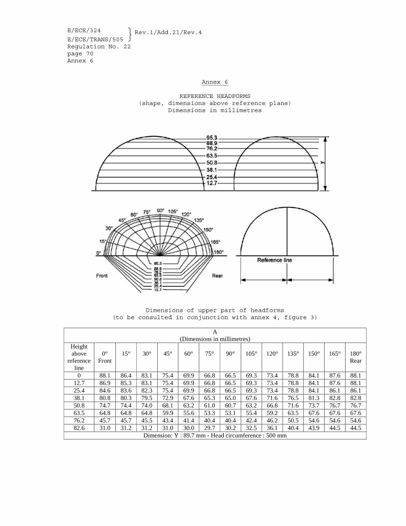
Annex 2 - Examples of arrangements of approval mark Annex 3 - Diagram of protective helmet Annex 4 - Headforms Annex 5 - Positioning of the helmet on the headform Annex 6 - Reference headforms (shape, dimensions above reference plane) Annex 7 - Reference headforms (shape, dimensions below reference plane) Annex 8 - Test machines Annex 9 - Testing of the angle of opening of the visor Annex 10 - Abrasion test procedure Annex 11 - Methods of measuring light diffusion and light transmission
coefficient Annex 12 B Type approval scheme (Flow chart) Annex 13 B Definitions Annex 14 B Product of the spectral distribution of radiation of the signal
light and standard illuminant D65 Annex 15 B Test of refractive powers Annex 16 B Test for mist-retardant visors
* * *
E/ECE/324 Rev.1/Add.21/Rev.4
E/ECE/TRANS/505 Regulation No. 22 page 5
1. SCOPE This Regulation applies to protective helmets for drivers and
passengers of mopeds and of motor cycles with or without side-car 1/ and to the visors fitted to such helmets or intended to be added to them.
2. DEFINITIONS 2/ For the purposes of this Regulation, 2.1. "protective helmet" means a helmet primarily intended to protect
the wearer's head against impact. Some helmets may provide additional protection;
2.2. "shell" means the hard part of the protective helmet, which
gives it its general shape; 2.3. "protective padding" means a material used to absorb impact
energy; 2.4. "comfort padding" means a material provided for the wearer's
comfort; 2.5. "retention system" means the complete assembly by means of which
the helmet is maintained in position on the head, including any devices for adjustment of the system or to enhance the wearer's comfort;
2.5.1. "chin-strap" means a part of the retention system consisting of
a strap that passes under the wearer's jaws to keep the helmet in position;
2.5.2. "chin-cup" means an accessory of the chin-strap that fits round
the point of the wearer's chin; 2.6. "peak" means an extension of the shell above the eyes; 2.7. "lower face cover" means a detachable, movable or integral
(permanently fixed) part of the helmet covering the lower part of the face;
2.7.1. "protective lower face cover" means a detachable, movable or
integral (permanently fixed) part of the helmet covering the lower part of the face and intended to protect the chin of the user against impacts;
1/ Protective helmets for wear in competitions may have to comply with stricter provisions. 2/ See also the diagram in annex 3.
E/ECE/324 Rev.1/Add.21/Rev.4
E/ECE/TRANS/505 Regulation No. 22 page 6 2.7.2. "non protective lower face cover" means a detachable or movable
part of the helmet covering the lower part of the face that does not protect the chin of the user against impacts;
2.8. "visor" means a transparent protective screen extending over the
eyes and covering all or part of the face; 2.9. "goggles" mean transparent protectors that enclose the eyes; 2.10. Disposable protective film 2.10.1. A removable plastic film may be applied to protect the visor
prior to use. In this case the film has to be opaque or printed, so that it must be removed before use.
2.10.2. A protective film (tear-off) may be used for racing for example
to reduce the level of luminous transmission. Such tear-off-films are not for use on the road and are not covered by this Regulation.
2.11. "ocular areas" mean two circles of minimum diameter 52 mm spaced
symmetrically about the vertical centre line of the visor, the distance between the centres of the circles being 64 mm measured in the horizontal front plane of the visor as worn.
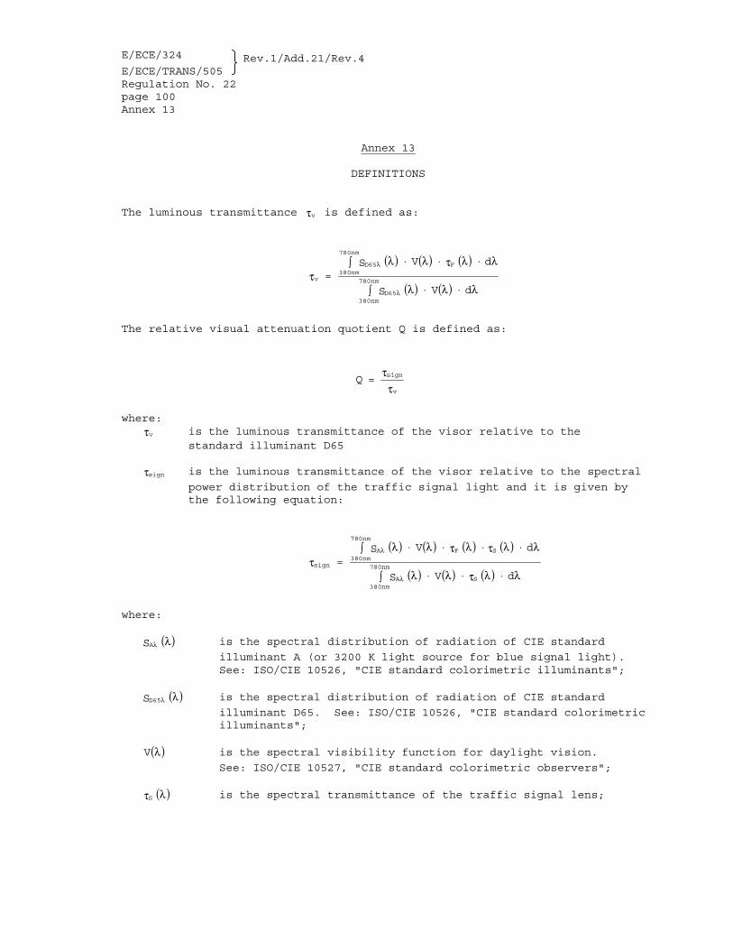
2.12. "luminous transmittance τv" is defined in annex 13. 2.13. "relative visual attenuation quotient" means the relative visual
quotient (Q) and is defined in annex 13. 2.14. "basic plane of the human head" means a plane at the level of
the opening of the external auditory meatus (external ear opening) and the lower edge of the orbits (lower edge of the eye sockets);
2.15. "basic plane of the headform" means a plane which corresponds to
the basic plane of the human head; 2.16. "reference plane" means a construction plane parallel to the
basic plane of the headform at a distance from it which is a function of the size of the headform;
2.17. "protective helmet type" means a category of protective helmets
which do not differ in such essential respects as: 2.17.1. the trade name or mark, or 2.17.2. the materials or dimensions of the shell, of the retention
system or of the protective padding. However, a protective helmet type may include a range of helmet sizes, provided that the thickness of the protective padding in each size in the range is at least equal to that in the protective helmet which
E/ECE/324 Rev.1/Add.21/Rev.4
E/ECE/TRANS/505 Regulation No. 22 page 7
when subjected to the tests satisfied the requirements of this Regulation;
2.18. "visor type" means a category of visors which do not differ
substantially in such essential characteristics as: 2.18.1. the trade name or mark, or 2.18.2. the materials, dimensions, manufacturing processes (such as
extrusion of moulding), colour, surface treatment, system of attachment to the helmet;
2.19. "approval test" means a test to determine the extent to which a
protective helmet type and/or a visor type submitted for approval is capable of satisfying the requirements;
2.20. "production quality test" means a test to determine whether the
manufacturer is able to produce helmets and/or visors in conforming with the helmets and/or visors submitted for type approval;
2.21. "routine testing" means the testing of a number of helmets
and/or visors selected from a single batch to verify the extent to which they satisfy the requirements.
3. APPLICATION FOR APPROVAL 3.1. Application for approval of a protective helmet type 3.1.1. The application for approval of a protective helmet type,
without or with one or more visor types, shall be submitted by the helmet manufacturer or by the holder of the manufacturer's name or trade mark or by his duly accredited representative, and for each type the application shall be accompanied by the following:
3.1.1.1. Drawings in triplicate to a scale of 1:1, in sufficient detail
to permit identification of the helmet type, including the methods of assembly. The drawings shall show the position intended for the approval mark as set out in paragraph 5.1.4.1.,
3.1.1.2. A brief technical specification stating the materials used and a
test report of the photometric and colorimetric performance of the retroreflective material.
3.1.1.3. If the helmet is fitted with one or more visors: 3.1.1.3.1. Drawings in triplicate to a scale of 1:1, in sufficient detail
to permit identification of the visor type and of its means of attachment to the helmet. The drawings shall show the position intended for the approval mark as set out in paragraph 5.1.4.1.,
E/ECE/324 Rev.1/Add.21/Rev.4
E/ECE/TRANS/505 Regulation No. 22 page 8 3.1.1.3.2. A technical description of the visor stating the materials used,
the manufacturing processes and, where appropriate, the surface treatment,
3.1.1.4. A number of helmets, with or without visors, out of 20 samples
of different sizes, sufficient to enable all the tests specified in paragraph 7.1. to be conducted and one helmet additionally to be retained by the technical service responsible for conducting the approval test.
3.1.1.5. For each visor type, if any, 7 (+3 if optional test for mist
retardant visor is carried out) visors taken from a sample of not less than 14 (+ 6 if optional test) specimens. 6 (+ 3 if optional test) visors shall be subjected to the tests and the seventh (or tenth if optional test) shall be retained by the technical service responsible for conducting the approval test.
3.2. Application for approval of a visor type 3.2.1. The application for approval of a visor type shall be submitted
by the visor manufacturer or by the holder of the manufacturer's name or trade mark or by his duly accredited representative, and for each type the application shall be accompanied by the following:
3.2.1.1. Drawings in triplicate to a scale of 1:1, in sufficient detail
to permit identification of the visor type and of its means of attachment to the helmet. The drawings shall show the position intended for the approval mark as set out in paragraph 5.2.4.1.,
3.2.1.2. A technical description of the visor stating materials used, the
manufacturing processes and, where appropriate, the surface treatment,
3.2.1.3. List of approved helmet types to which the visor may be fitted, 3.2.1.4. For each visor type, if any, 7 (+3 if optional test for mist
retardant visor is carried out) visors taken from a sample of not less than 14 (+ 6 if optional test) specimens and the helmets to which the visors are intended to be fitted. 6 (+ 3 if optional test) visors shall be subjected to the tests and the seventh (or tenth if optional test) shall be retained by the technical service responsible for conducting the approval test.
3.3. The competent authority shall verify the existence of
satisfactory arrangements in order to ensure effective control of the conformity of production in accordance with the provisions of paragraph 10. and annex 12 before type approval is granted.
E/ECE/324 Rev.1/Add.21/Rev.4
E/ECE/TRANS/505 Regulation No. 22 page 9
4. MARKINGS 4.1. The protective helmets submitted for approval in conformity with
paragraph 3.1. above shall bear: 4.1.1. On the helmet, the applicant's trade name or mark and an
indication of the size and, if appropriate, an indication of the unsuitability of the lower face cover to offer any protection against impacts to the chin.
4.1.2. On the visor, the applicant=s trade name or mark and, if
appropriate, an indication of the unsuitability of the visor for use during the hours of darkness or in conditions of poor visibility.
4.2. The visors submitted for approval in conformity with
paragraph 3.2. above shall bear the applicant's trade name or mark and, if appropriate, an indication of the unsuitability of the visor for use during the hours of darkness or in conditions of poor visibility.
4.3. The marking shall not be placed within the main visibility area. 4.4. The marking shall be indelible, clearly legible and in readily
accessible place. 5. APPROVAL 5.1. Approval of a protective helmet type, without or with one or more
visor types 5.1.1. If the protective helmets and the visors, if any, submitted in
pursuance of paragraph 3.1.1.4. above meet the requirements of this Regulation, approval shall be granted.
5.1.2. An approval number shall be assigned to each type approved. Its
first two digits (at present 05) shall indicate the series of amendments incorporating the most recent major technical amendments made to the Regulation at the time of issue of the approval. The same Contracting Party shall not assign the same number to another helmet type covered by this Regulation.
5.1.3. Notice of approval or of extension or refusal or withdrawal of
approval or production definitely discontinued of a protective helmet type, without or with one or more visor types pursuant to this Regulation shall be communicated to the Parties to the 1958 Agreement applying this Regulation, by means of a form conforming to the model in annex 1 A to this Regulation.
E/ECE/324 Rev.1/Add.21/Rev.4
E/ECE/TRANS/505 Regulation No. 22 page 10 5.1.4. In addition to the marks described in paragraph 4.1.1. above,
the following particulars shall be indicated on every protective helmet conforming to a type approved under this Regulation by means of the labels referred to in paragraph 5.1.9. below:
5.1.4.1. An international approval mark consisting of: 5.1.4.1.1. A circle surrounding the letter "E" followed by the
distinguishing number of the country which has granted approval, 3/
5.1.4.1.2. The approval number followed by: 5.1.4.1.2.1. a dash and symbol: "J" if the helmet does not have a lower face cover "P" if the helmet has a protective lower face cover, or "NP" if the helmet has a non protective lower face cover 5.1.4.1.2.2. a dash followed by a production serial number. The production
serial numbers shall be continuous for all protective helmets of the types approved in the same country, and each authority shall keep a register from which it can check that the type and production serial numbers correspond.
5.1.4.1.3. The marking and/or symbol denoting the unsuitability of the
lower face cover, if appropriate. 5.1.4.1.4. The marking on the helmet and, if appropriate, lower face cover
shall be clearly legible, indelible and resistant to wear. 5.1.5. In addition to the marks described in paragraph 4.1.2. above, the
3/ 1 for Germany, 2 for France, 3 for Italy, 4 for the Netherlands, 5 for Sweden, 6 for Belgium, 7 for Hungary, 8 for the Czech Republic, 9 for Spain, 10 for Yugoslavia, 11 for the United Kingdom, 12 for Austria, 13 for Luxembourg, 14 for Switzerland, 15 (vacant), 16 for Norway, 17 for Finland, 18 for Denmark, 19 for Romania, 20 for Poland, 21 for Portugal, 22 for the Russian Federation, 23 for Greece, 24 for Ireland, 25 for Croatia, 26 for Slovenia, 27 for Slovakia, 28 for Belarus, 29 for Estonia, 30 (vacant), 31 for Bosnia and Herzegovina, 32 for Latvia, 33 (vacant), 34 for Bulgaria, 35 (vacant), 36 for Lithuania, 37 for Turkey, 38 (vacant), 39 for Azerbaijan, 40 for The former Yugoslav Republic of Macedonia, 41 (vacant), 42 for the European Community (Approvals are granted by its Member States using their respective ECE symbol), 43 for Japan, 44 (vacant), 45 for Australia, 46 for Ukraine, 47 for South Africa and 48 for New Zealand. Subsequent numbers shall be assigned to other countries in the chronological order in which they ratify or accede to the Agreement Concerning the Adoption of Uniform Technical Prescriptions for Wheeled Vehicles, Equipment and Parts which can be Fitted and/or be Used on Wheeled Vehicles and the Conditions for Reciprocal Recognition of Approvals Granted on the Basis of these Prescriptions, and the numbers thus assigned shall be communicated by the Secretary-General of the United Nations to the Contracting Parties to the Agreement.
E/ECE/324 Rev.1/Add.21/Rev.4
E/ECE/TRANS/505 Regulation No. 22 page 11
following particulars shall be affixed visibly and in a readily accessible place to every visor, if any, conforming to a type approved with a helmet under this Regulation:
5.1.5.1. An international approval mark consisting of: 5.1.5.1.1. A circle surrounding the letter "E" followed by the
distinguishing number of the country which has granted approval, 3/
5.1.5.1.2. A reference alphanumerical number. 5.1.5.1.3. The symbol denoting daytime use only, if appropriate. 5.1.6. The marking on the visor shall be clearly legible, indelible and
resistant to wear. 5.1.7. The marking on the visor shall not be placed within the main
visibility area. 5.1.8. Annex 2 A to this Regulation gives examples of the arrangements
of the approval marks for protective helmets and visors. 5.1.9. In order to be considered as approved under this Regulation,
subject to the provisions of paragraph 9. below, every protective helmet shall bear, sewn to its retention system, one of the labels referred to in paragraph 5.1.4. above. A different method of securing the label is authorized if it complies with the above provisions.
5.1.10. The labels referred to in paragraph 5.1.9. above may be issued
either by the authority which has granted the approval or, subject to that authority's authorization, by the manufacturer.
5.1.11. The label referred to in paragraph 5.1.9. above shall be clearly
legible and resistant to wear. 5.1.12. Approval of helmets of size 48/49 shall be granted without
additional tests if such helmets belong to a type already approved which comprises size 50 in its range of sizes.
5.1.13. Approval of helmets larger than size 62 shall be granted without
additional tests if such helmets belong to a type already approved which comprises size 62 in its range of sizes.
5.2. Approval of a visor type 5.2.1. Where the visors submitted in accordance with paragraph 3.2.1.4.
above meet the requirements of paragraphs 6.15. and 7.8. of this Regulation, approval shall be granted.
5.2.2. An approval number shall be assigned to each type approved. Its
first two digits (at present 05) shall indicate the series of
E/ECE/324 Rev.1/Add.21/Rev.4
E/ECE/TRANS/505 Regulation No. 22 page 12
amendments incorporating the most recent major technical amendments made to the Regulation at the time of issue of the approval. The same Contracting Party shall not assign the same number to another visor type covered by this Regulation.
5.2.3. Notice of approval or of extension or refusal or withdrawal of
approval or production definitely discontinued of a visor type pursuant to this Regulation shall be communicated to the Parties to the 1958 Agreement applying this Regulation, by means of a form conforming to the model in annex 1 B to this Regulation.
5.2.4. In addition to the marks prescribed in paragraph 4.2. above, the
following particulars shall be affixed visibly and in a readily accessible place to every visor conforming to a type approved under this Regulation:
5.2.4.1. An international approval mark consisting of: 5.2.4.1.1. the approval symbol described in paragraph 5.1.4.1.1., 5.2.4.1.2. the approval number, 5.2.4.1.3. the symbol denoting daytime use only, if appropriate. 5.2.5. The approval mark shall be clearly legible, indelible and
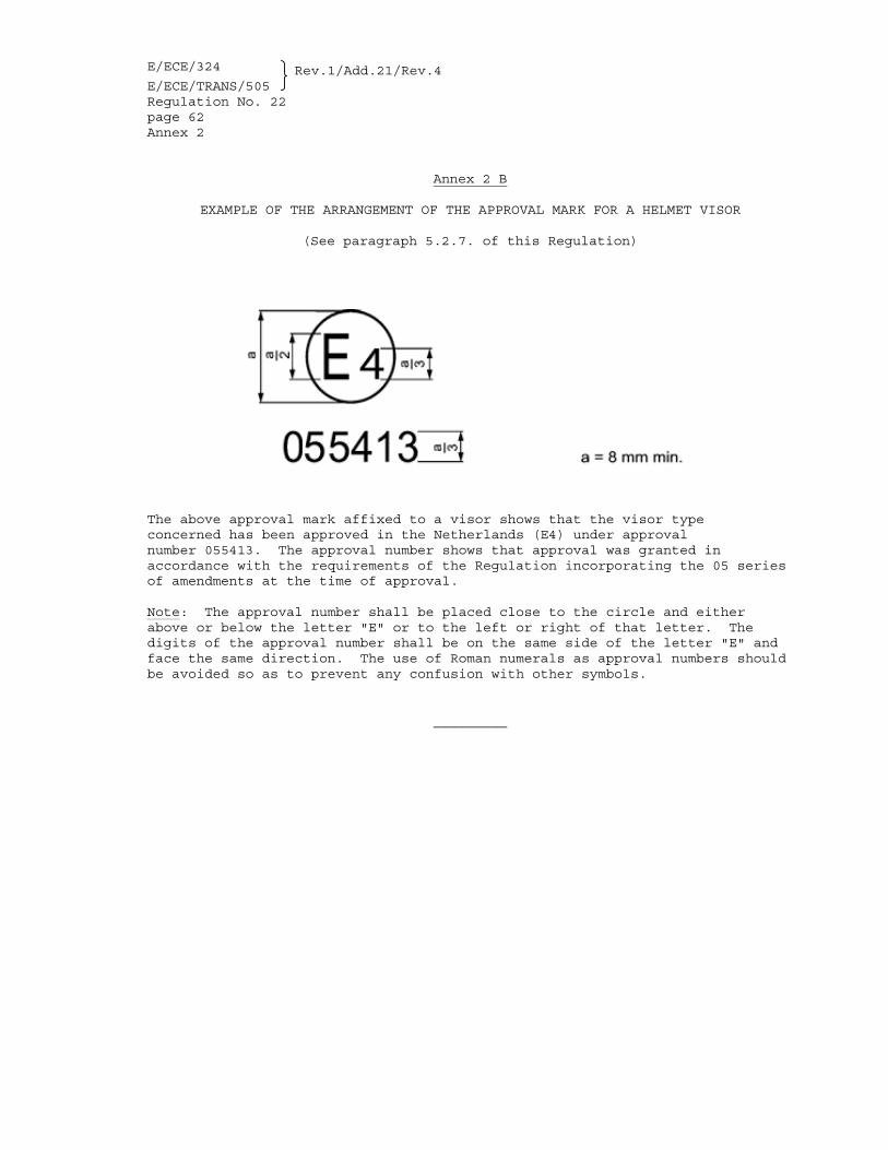
resistant to wear. 5.2.6. The marking shall not be placed within the main visibility area. 5.2.7. Annex 2 B to this Regulation gives an example of the arrangement
of approval mark for a visor. 6. GENERAL SPECIFICATIONS 6.1. The basic construction of the helmet shall be in the form of a
hard outer shell, containing additional means of absorbing impact energy, and a retention system.
6.2. The protective helmet may be fitted with ear flaps and a neck
curtain. It may also have a detachable peak, a visor and a lower face cover. If fitted with a non protective lower face cover the outer surface of the cover shall be marked "Does not protect chin from impacts" and/or with the symbol shown in figure 1 below indicating the unsuitability of the lower face cover to offer any protection against impacts to the chin.
E/ECE/324 Rev.1/Add.21/Rev.4
E/ECE/TRANS/505 Regulation No. 22 page 13
Figure 1: Symbol "Does not protect chin from impacts@ 6.3. No component or device may be fitted to or incorporated in the
protective helmet unless it is designed in such a way that it will not cause injury and that, when it is fitted to or incorporated in the protective helmet, the helmet still complies with the requirements of this Regulation.
6.4. The extent of the protection provided shall be as follows: 6.4.1. The shell shall cover all areas above plane AA' and shall extend
downwards at least as far as the lines CDEF on both sides of the headform (see annex 4, fig. 1 A).
6.4.2. At the rear, the rigid parts and, in particular, the shell shall
not be within a cylinder defined as follows (see annex 4, fig. 1 B):
(i) Diameter 100 mm; (ii) Axis, situated at the intersection of the medium plane of
symmetry of the headform and of a plane parallel to and 110 mm below the reference plane.
6.4.3. The protective padding shall cover all the areas defined in
paragraph 6.4.1., account being taken of the requirements of paragraph 6.5.
6.5. The helmet shall not dangerously affect the wearer's ability to
hear. The temperature in the space between the head and the shell shall not rise inordinately; to prevent this, ventilation holes may be provided in the shell.
Where means for attaching a visor are not provided, the profile
at the front edge shall not prevent the wearing of goggles. 6.6. All projections from or irregularities in the outer surface of
the shell greater than 2 mm shall be tested for shear assessment according to paragraphs 7.4.1. or 7.4.2. The outer surface of the helmet shall be tested for friction assessment according to paragraphs 7.4.1. or 7.4.2.
E/ECE/324 Rev.1/Add.21/Rev.4
E/ECE/TRANS/505 Regulation No. 22 page 14 6.7. All external projections shall be radiused and any external
projections other than press-fasteners shall be smooth and adequately faired.
6.7.1. All external projections not more than 2 mm above the outer
surface of the shell (e.g. rivet heads) shall have a radius of a minimum of 1 mm.
6.7.2. All external projections more than 2 mm above the outer surface
of the shell shall have a radius of a minimum of 2 mm. The latter specific requirements shall not apply if a projection
satisfies the requirements in paragraphs 7.4.1. or 7.4.2. below. 6.8. There shall be no inward-facing sharp edges on the inside of the
helmet; rigid, projecting internal parts shall be covered with padding so that any stresses transmitted to the head are not highly concentrated.
6.9. The various components of the protective helmet shall be so
assembled that they are not liable to become easily detached as a result of an impact.
6.10. Retention systems shall be protected from abrasion. 6.11. The helmet shall be held in place on the wearer's head by means
of a retention system which is secured under the lower jaw. All parts of the retention system shall be permanently attached to the system or to the helmet.
6.11.1. If the retention system includes a chin-strap, the strap shall
be not less than 20 mm wide under a load of 150 N " 5 N applied under the condition prescribed in paragraph 7.6.2.
6.11.2. The chin strap shall not include a chin-cup. 6.11.3. Chin straps shall be fitted with a device to adjust and maintain
tension in the strap. 6.11.4. Chin strap fastening and tensioning devices shall be positioned
on the straps either so that there are no rigid parts extending more than 130 mm vertically below the headform reference plane with the helmet mounted on the appropriate sized headform, or so that the whole of the device is between the bony projections of the underside of the lower jaw.
6.11.5. If the retention system includes either a double-D ring or
sliding bar fastening device then means shall be provided to prevent the retention system being completely undone and also to retain the free end of the strap when the retention system is adjusted.
E/ECE/324 Rev.1/Add.21/Rev.4
E/ECE/TRANS/505 Regulation No. 22 page 15
6.11.6. Sliding bar and double-D ring fastening devices shall be fitted with a pulling flap to be used for releasing the retention system. Its colour must be red and its minimum dimensions must be 10 x 20 mm.
6.11.7. If a retention system includes a quick-release mechanism, then
the method of release of this mechanism shall be self-evident. Any levers, tabs, buttons or other components which need to be operated to release the mechanism shall be coloured red, those parts of the rest of the system which are visible when closed shall not be similarly coloured, and the mode of operation shall be permanently indicated.
6.11.8. The retention system shall remain closed when the tests
described in paragraphs 7.3., 7.6. and 7.7. are carried out. 6.11.9. The buckle of the retention system shall be designed so as to
preclude any possibility of incorrect manipulation. This means, inter alia, that it must not be possible for the buckle to be left in a partially closed position.
6.12. The characteristics of the materials used in the manufacture of
helmets shall be known not to undergo appreciable alteration under the influence of ageing, or of the circumstances of use to which the helmet is normally subjected, such as exposure to sun, extremes of temperature and rain. For those parts of the helmet coming into contact with the skin, the materials used shall be known not to undergo appreciable alteration through the effect of perspiration or of toilet preparations. The manufacturer shall not use materials known to cause skin troubles. The suitability of a proposed new material shall be established by the manufacturer.
6.13. After the performance of one of the prescribed tests, the
protective helmet shall not exhibit any breakage or deformation dangerous to the wearer.
6.14. Peripheral vision 6.14.1. To carry out the test, the technical service shall select from
among the existing sizes of a helmet type the size it considers likely to yield the least favourable result;
6.14.2. The helmet shall be placed on the headform corresponding to its
size by the procedure set out in annex 5 to this Regulation; 6.14.3. In the above conditions there shall be no occultation in the
field of vision bounded by: (see annex 4, figs. 2A, 2B and 2C) 6.14.3.1. horizontally: two segments of dihedral angles symmetrical in
relation to the median longitudinal vertical plane of the headform and situated between the reference and the basic planes.
E/ECE/324 Rev.1/Add.21/Rev.4
E/ECE/TRANS/505 Regulation No. 22 page 16 Each of these dihedral angles is defined by the median
longitudinal vertical plane of the headform and the vertical plane forming an angle of not less than 105° with the median longitudinal vertical plane and whose edge is the straight line LK;
6.14.3.2. upwards: a dihedral angle defined by the reference plane of the
headform and a plane forming an angle of not less than 7° with the reference plane and whose edge is the straight line L1 L2, the points L1 and L2 representing the eyes;
6.14.3.3. downwards: a dihedral angle defined by the basic plane of the
headform and a plane forming an angle of not less than 45° with the basic plane and whose edge is the straight line K1 K2.
6.15. Visors 6.15.1. The systems of attachment of a visor to a helmet shall be such
that the visor is removable. It must be possible to manoeuvre the visor out of the field of vision with a simple movement of one hand. However, the latter prescription may not be required for helmets which do not provide chin protection provided that a label is attached to the helmet to the effect of warning the purchaser that the visor cannot be manoeuvred.
6.15.2. Angle opening (see annex 9) 6.15.3. Field of vision 6.15.3.1. The visor shall not comprise any part liable to impair the
user's peripheral vision as defined in paragraph 6.14. when the visor is in the totally opened position. Furthermore, the lower edge of the visor shall not be situated in the downward field of vision of the user as defined in paragraph 6.14. when the visor is in closed position. The surface of the visor in the peripheral field of vision of the helmet may however include:
(i) The lower edge of the visor, provided that it is made of a
material with at least the same transmittance as the rest of the visor,
(ii) A device to allow the visor to be manoeuvred. However, if
this device is situated within the field of vision of the visor defined in paragraph 6.15.3.2. below it shall be at the lower edge and present a maximum height (h) of 10 mm and its width (l) shall be such that the product (h x l) at the most is equal to 1.5 cm2. Moreover, it must be made of a material with at least the same transmittance as the visor and it must be free of any engraving, paint or other covering feature,
E/ECE/324 Rev.1/Add.21/Rev.4
E/ECE/TRANS/505 Regulation No. 22 page 17
(iii) Fixings and devices to allow the visor to be manoeuvred if they are situated outside of the field of vision of the visor and if the total surface of these parts, including devices, if any, to allow the visor to be manoeuvred does not exceed 2 cm2, possibly distributed on each side of the field of vision.
6.15.3.2. The field of vision of the visor is defined by: (a) A dihedron defined by the reference plane of the headform
and a plane forming an angle of at least 7° upwards, its edge being the straight line L1 L2, with points L1 and L2 representing the eyes,
(b) Two segments of dihedral angles symmetrical to the median
vertical longitudinal plane of the headform. Each of these dihedral angles is defined by the median vertical longitudinal plane of the headform and the vertical plane forming with this plane an angle of 90°, its edge being the straight line LK,
(c) and the lower edge of the visor. 6.15.3.3. To determine the field of vision as defined in
paragraph 6.15.3.2. above, the helmet fitted with the visor being tested shall be placed on a test headform of suitable size in accordance with the provisions of paragraph 7.3.1.3.1., with the helmet tipped towards the rear as specified in paragraph 7.3.1.3.1. and the visor placed in the closed position.
6.15.3.4. Visors shall have a luminous transmittance τv $ 80%, relative to
the standard illuminant D65. A luminous transmittance 80% > τv $ 50%, measured by the method given in paragraph 7.8.3.2.1.1., is also permissible if the visor is marked with the symbol shown in figure 2 and/or with the English words ADAYTIME USE ONLY@. The luminous transmittance shall be measured before the abrasion test.
Figure 2: Symbol "Daytime use only"
E/ECE/324 Rev.1/Add.21/Rev.4
E/ECE/TRANS/505 Regulation No. 22 page 18 6.15.3.5. Visors shall be free from any significant defects likely to
impair the vision, such as bubbles, scratches, inclusions, dull spots, holes, mould marks, scratches or other defects originating from the manufacturing process in the field of vision. The light diffusion shall not exceed the limit in accordance with paragraph 7.8.3.2.1.2. when measured in accordance with one of the methods specified in annex 11.
If different results arise when this is assessed, the
requirements on scattered light shall be measured and assessed over an area 5 mm in diameter which includes the presumed error. In addition, the regular transmittance shall not deviate by more than " 5 per cent from the reference value, measured in one of two sight points specified in paragraph 6.15.3.8., at any point within the field of vision of the visor.
6.15.3.6. Visors shall in addition be sufficiently transparent, shall not
cause any noticeable distortion of object as seen through the visor, shall be resistant to abrasion, resistant to impact and shall not give rise to any confusion between the colour used in road traffic sign and signals. The relative visual attenuation quotient (Q) shall not be less than: 0.80 for red and yellow signal lights; 0.60 for green signal light; 0.40 for blue signal light.
The relative attenuation quotient shall be measured by the method given in paragraph 7.8.3.2.1.1., before the abrasion test.
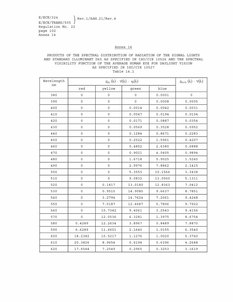
Note: When calculating the value of Q from the spectral measurements, the value in annex 14 shall be used. Linear interpolation of these values for steps smaller than 10 nm is permissible.
6.15.3.7. In the range 500 nm to 650 nm, the spectral transmittance,
measured by the method given in paragraph 7.8.3.2.1.1., of the visor shall not be less than 0.2 τv. The spectral transmittance shall be measured before the abrasion test.
6.15.3.8. The table contains the permissible refractive powers at the
sight points. The sight points are located in the reference plane 32 mm to the right and the left of the longitudinal median plane (see fig. 2B).
E/ECE/324 Rev.1/Add.21/Rev.4
E/ECE/TRANS/505 Regulation No. 22 page 19
Permissible refractive power values for visors
Spherical effect
Astigmatic
effect
Prismatic effect difference
Horizontal
2D + D 21
m-1
|D - D| 21
m-1
Base Out
cm/m
Base In
cm/m
Vertical
cm/m
" 0.12
0.12
1.00
0.25
0.25
D1, D2: Refractive effect in two main sectors
The requirements for the prismatic effect apply to the difference between the values at the two sight points.
The refractive powers shall be measured according to method specified in annex 15.
The internal face of the visor is regarded as having a mist retardant facility if the square of the specular transmittance has not fallen below 80 per cent of the initial value without misting within 20 s when tested as described in annex 16. Such facility may be indicated by the English words AMIST RETARDANT@.
6.16. Conspicuity marking 6.16.1. General In order to comply with national requirements for use, the
helmet may be required by individual Contracting Parties to contribute to the conspicuity of the user both during the daytime and at night:
from the front; from the rear; from the right; from the left by means of parts made of reflective materials which conform to
the specifications laid down in paragraphs 6.16.2. to 6.16.6. of this Regulation.
The reflective parts shall not be removable without damage to the helmet.
E/ECE/324 Rev.1/Add.21/Rev.4
E/ECE/TRANS/505 Regulation No. 22 page 20 Note: The mandating of conspicuity marks is left to the
discretion of individual Contracting Parties. Article 3 of the Agreement to which this Regulation is annexed shall not prevent the Contracting Parties from prohibiting the use of helmets not meeting the conspicuity requirements.
6.16.2. Reflective parts 6.16.2.1. Geometry The total surface area and shape of the reflective part used
shall be such that in each direction, corresponding to one of the areas defined in the figure below, visibility is ensured by a surface area of at least 18 cm2 of simple shape and measured by application on a plane.
In each surface area of minimum 18 cm2 it shall be possible to
mark: either a circle of 40 mm diameter; or, a rectangle at least 12.5 cm2 in surface area and at least
20 mm in width. Each of these surfaces shall be situated as near as possible to
the point of contact with the shell of a vertical plane parallel to the longitudinal vertical plane of symmetry, to the right and to the left, and as near as possible to the point of contact with the shell of a vertical plane perpendicular to the longitudinal plane of symmetry, to the front and to the rear.
E/ECE/324 Rev.1/Add.21/Rev.4
E/ECE/TRANS/505 Regulation No. 22 page 21
6.16.3. Colorimetric test Each of the retroreflective areas shall emit white light when it
is illuminated with a standard illuminant A, with an observation angle of 1/3E and an illumination angle β1 = β2 = 0E (or β1 = " 5E, β2 = 0E); in other words: the trichromatic coordinates "x" and "y" of the reflected light shall lie within the zone specified below:
White: limit towards blue x $ 0.310 limit towards yellow x # 0.500 limit towards green y # 0.150 + 0.640x limit towards green y # 0.440 limit towards purple y $ 0.050 + 0.750x limit towards red y $ 0.382 6.16.4. Photometric test The minimum value of the luminous intensity coefficient of a
surface area of 18 cm2 of material when revolved shall not be less than the values specified in the table below, expressed in millicandelas per lux.
Angle of Divergence
Angle of Illumination
0E 20E 40E 20' 100 60 25
6.16.5. Resistance to external agent After each conditioning as described in paragraph 7.2., the helmet
shall be visually inspected. There shall be no signs of cracking or appreciable distortion of the retroreflective material.
6.16.6. Compatibility of materials Neither the adhesive nor the retroreflective material shall affect
the mechanical performance of the helmet according to the related tests in the present Regulation.
7. TESTS 7.1. Each helmet type, fitted with its visor if placed on the market
with a visor, shall be conditioned as shown below.
E/ECE/324 Rev.1/Add.21/Rev.4
E/ECE/TRANS/505 Regulation No. 22 page 22
Test
Number of helmets to be conditioned Total
solvent plus ambient-temperature and hygrometry conditioning
solvent plus heat conditioning
solvent plus low-temperature conditioning
solvent plus ultra- violet radiation conditioning and moisture conditioning
The largest size of each helmet type shall be tested for impact absorption and rigidity. For tests of the retention system, helmet sizes shall be chosen such that the helmet to be tested shall be that offering the least favourable conditions (such as thickest padding, etc).
Additionally, for each smaller headform size within the size range
of the helmet type two helmets shall undergo the impact absorption test. One helmet shall be heat conditioned, and the other low temperature conditioned. The conditioned helmets shall be impacted against either anvil, in equal numbers if possible, at the choice of the laboratory.
7.2. Types of conditioning Prior to any type of further conditioning for mechanical tests, as
specified in paragraph 7.1., each helmet shall be subject to solvent conditioning.
7.2.1. Solvent conditioning Take a cotton cloth approximately 150 mm square and a quantity
approximately 25 ml of a solvent consisting of test liquid B in accordance with ISO 1817:1985 4/. Using the cloth soaked in the solvent, apply the solvent to all those regions of the outside surface of the helmet within 50 mm of the chin strap fixings, and keep these regions wet with the solvent for (7.5 " 2.5) s. Repeat the procedure on the remainder of the external surface including any chin guard, keeping these regions wet for (12.5 " 2.5) s. Do not carry out any further conditioning or testing during the following 30 min.
7.2.2. Ambient-temperature and hygrometry conditioning The helmet shall be exposed to a temperature of 25 °C " 5 °C and a
relative humidity of 65% " 5% for at least 4 hours.
4/ e.g. 70 per cent octane and 30 per cent toluene.
E/ECE/324 Rev.1/Add.21/Rev.4
E/ECE/TRANS/505 Regulation No. 22 page 23
7.2.3. Heat conditioning The helmet shall be exposed to a temperature of 50 °C + 2 °C for
not less than 4 hours and not more than 6 hours. 7.2.4. Low-temperature conditioning The helmet shall be exposed to a temperature of -20 °C + 2 °C for
not less than 4 hours and not more than 6 hours. 7.2.5. Ultraviolet-radiation conditioning and moisture conditioning The outer surface of the protective helmet shall be exposed
successively to: 7.2.5.1. ultraviolet irradiation by a 125-watt xenon-filled quartz lamp
for 48 hours at a range of 25 cm; 7.2.5.2. spraying for 4 to 6 hours with water at ambient temperature at
the rate of 1 litre per minute. 7.3. Impact-absorption tests 7.3.1. Description of test 7.3.1.1. Principle Impact absorption capacity is determined by recording against
time the acceleration imparted to a headform fitted with the helmet, when dropped in guided free fall at a specific impact velocity upon a fixed steel anvil.
7.3.1.2. Marking of points and areas of impact Before conditioning, the points and areas of impact are marked as
indicated in paragraph 7.3.4.2. and annex 4 (fig. 3) and the helmet is positioned in accordance to annex 5.
7.3.1.3. Positioning of the helmet After conditioning: 7.3.1.3.1. The helmet shall be positioned in accordance with the
requirements of annex 5 on a headform of appropriate size selected from among those listed in paragraph 7.3.3.2. 5/ When testing impact points B, X, P and R the helmet is tipped towards the rear so that the front edge of the helmet in the median plane is displaced by 25 mm; the retention system is then adjusted
5/ Helmets of sizes not listed in paragraph 7.3.3.2. shall be tested with the next smaller headform listed. Helmets of size 62 or larger shall be tested with the headform "O".
E/ECE/324 Rev.1/Add.21/Rev.4
E/ECE/TRANS/505 Regulation No. 22 page 24
under the chin of the headform; if the system includes an adjustable chin strap, the strap is tightened as for normal use.
7.3.1.3.1.1. When testing impact point S on a helmet with a protective lower
face cover, the helmeted headform is tipped forwards so that the central vertical axis of the headform is inclined at an angle of 65 " 3° to the vertical with the vertical longitudinal plane of symmetry of the helmeted headform in the vertical position. If the impact point would be within 15 mm of the rim, the helmeted headform shall be re-positioned so that the impact point is not less than 15 mm from the rim.
7.3.1.3.2. The test headform shall be so positioned that the designated
point on the helmet is vertically above the centre of the anvil. The plane tangential to the point of impact shall be horizontal. This prescription does not apply for the S impact point.
7.3.1.3.3. Helmets placed on the market with a visor shall be tested with
the visor in the closed position. 7.3.1.4. Test
The test shall be completed not more than five minutes after the helmet is taken from the conditioning chamber. Tests at point S shall be carried out after tests at points B, X, P and R. The drop height shall be equal to: 7.5 (+ 0.15/- 0.0) m/s for both anvils specified in paragraphs 7.3.2.3.1. and 7.3.2.3.2. 5.5 (+ 0.15/ -0.0) m/s for tests at point S.
7.3.1.5. Measurements The velocity of the moving mass is measured between 1 cm and 6 cm
before impact, to an accuracy of 1 per cent. The acceleration against time at the centre of gravity of the headform is measured and recorded and the Head Injury Criterion (HIC) calculated as prescribed in paragraph 7.3.2.5.
7.3.2. Apparatus (see annex 8, fig. 1) 7.3.2.1. Description The test apparatus shall comprise: (a) An anvil rigidly fixed to a base; (b) A free fall guidance system; (c) A mobile system supporting the helmeted headform;
E/ECE/324 Rev.1/Add.21/Rev.4
E/ECE/TRANS/505 Regulation No. 22 page 25
(d) A metal headform fitted with a tridirectional accelerometer and a measuring assembly;
(e) A system by which the point of impact can be brought into
correspondence with the centre of the anvil. 7.3.2.2. Base The base shall be made of steel or concrete or a combination of
these materials and have a mass of at least 500 kg. It shall be so constructed that there is no significant
deformation of the surface under the test load. No part of the base or anvil shall have a resonance frequency
liable to affect the measurements. 7.3.2.3. Anvils 7.3.2.3.1. The flat steel anvil shall have a circular impact face of
diameter 130 mm " 3 mm. 7.3.2.3.2. The kerbstone anvil shall have two sides forming an angle of
105 " 5°, each of them with a slope of 52.5 " 2.5° towards the vertical and meeting along a striking edge with a radius of 15 mm " 0.5 mm. The height must be at least 50 mm and the length not less than 125 mm. The orientation is 45° to the longitudinal vertical plane at points B, P, and R, and 45° to the base plane at point X (front low, back up).
7.3.2.4. Mobile system and guides The mobile system supporting the headform shall be such that its
characteristics do not affect the measurement of acceleration at the centre of gravity of the headform. It shall also be such that any point in the area ACDEF can be positioned vertically above the centre of the anvil.
The guides shall be such that the impact velocity is not less
than 95 per cent of the theoretical velocity. 7.3.2.5. Accelerometer and measuring assembly The accelerometer shall be capable of withstanding a maximum
acceleration of 2,000 g without damage. Its maximum mass shall be 50 grammes. The measuring system, including the drop assembly, shall have a frequency response in accordance with channel frequency class (CFC) 1000 of the International Standard ISO "Road vehicles - Techniques of measurement in impact tests - Instrumentation" (Ref. No. ISO 6487:1980).
E/ECE/324 Rev.1/Add.21/Rev.4
E/ECE/TRANS/505 Regulation No. 22 page 26
The HIC shall be calculated as the maximum (depending from t1 and t2) of the equation:
( )HICt t
at dt t tt
t
=− ∫
−1
2 1 2
12 5
2 1( )
.
where 'a' is the resultant acceleration as a multiple of 'g' and
t1 and t2 are any two points in time (sec) during the impact. The acceleration data has to be sampled at a frequency of at least 8,000 Hz and filtered in accordance with the latest edition of ISO 6487 (CFC 1000).
7.3.3. Headforms 7.3.3.1. The headforms used for the impact-absorption tests shall be made
of a metal of characteristics such that the headforms present no resonance frequency below 3,000 Hz.
7.3.3.2. The general characteristics of the test headforms to be used
shall be as follows:
Symbols Size (in cm) Mass (in kg) A 50 3.1 " 0.10 E 54 4.1 " 0.12 J 57 4.7 " 0.14 M 60 5.6 " 0.16 O 62 6.1 " 0.18
7.3.3.3. The shape of the test headforms shall be: (a) Above the reference plane, in conformity with the detailed
dimensions of the reference headforms shown in annex 6; (b) Below the reference plane, in conformity with the detailed
dimensions of the test headforms shown in annex 7. 7.3.3.4. The centre of gravity of the headform shall be near the point G
on the central vertical axis at "l" mm below the reference plane, as defined in annex 7. The headform shall contain, near its centre of gravity, a housing for a tridirectional accelerometer.
7.3.3.5. For tests other than those of impact-absorption, headforms
complying only with the geometrical provisions of paragraph 7.3.3.3. above, may be used.
7.3.4. Selection of points of impact 7.3.4.1. Each test shall be carried out with 4 impacts on one helmet on
the points B, X, P and R, in this sequence. When a helmet with
E/ECE/324 Rev.1/Add.21/Rev.4
E/ECE/TRANS/505 Regulation No. 22 page 27
a protective lower face cover is being tested then an additional point S shall be impacted after the four other points, but only against the anvil specified in paragraph 7.3.2.3.1.
7.3.4.1.1. After each impact the helmet shall be re-positioned correctly on
the headform prior to the next impact, without interfering with the adjustment of the retention system. Before each impact on the point S the helmet shall be re-positioned correctly on the headform and the retention system adjusted under the chin of the headform; if the system includes an adjustable chin strap, the strap is tightened as much as possible.
7.3.4.2. The points of impact are defined for each helmet:
B, in the frontal area, situated in the vertical longitudinal plane of symmetry of the helmet and at an angle of 20° measured from Z above the AA' plane.
X, in either the left or right lateral area, situated in the
central transverse vertical plane and 12.7 mm below the AA' plane.
R, in the rear area, situated in the vertical longitudinal
plane of symmetry of the helmet and at an angle of 20° measured from Z above the AA' plane.
P, in the area with a radius of 50 mm and a centre at the
intersection of the central vertical axis and the outer surface of the helmet shell.
S, in the lower face cover area, situated within an area
bounded by a sector of 20° divided symmetrically by the vertical longitudinal plane of symmetry of the helmet.
Impacts at points B, X and R should be within 10 mm radius of the defined point.
7.3.5. Combination of conditioning and anvils Conditioning: Solvent plus ... Anvils a/
Ambient Flat and kerbstone
Heat Kerbstone b/
Low temperature c/ Flat b/
Ultraviolet radiation and moisture Flat or kerbstone
(to be selected by the laboratory)
a/ Point S shall only be impacted against the flat anvil. b/ Only for the largest helmet size. For smaller headforms in the size
range of the helmet type either anvil may be used. See paragraph 7.1. c/ Only each helmet size subjected to low-temperature conditioning shall
undergo the impact test at point S.
E/ECE/324 Rev.1/Add.21/Rev.4
E/ECE/TRANS/505 Regulation No. 22 page 28 7.3.6. The absorption efficiency shall be considered sufficient where
the resultant acceleration measured at the centre of gravity of the headform at no time exceeds 275 g, and the Head Injury Criterion does not exceed 2400.
The helmet shall not become detached from the headform. 7.4 Test for projections and surface friction An appropriate size of helmet shall be subjected to the test
described in paragraph 7.4.1. or to the test described in paragraph 7.4.2.
7.4.1. Test for projections and surface friction (method A) 7.4.1.1. Description of test 7.4.1.1.1. Principle
The rotation-inducing forces caused by projections on the helmet and friction against the outer surface of the helmet which occur when a helmeted headform is dropped vertically on to an inclined anvil are measured in the longitudinal axis of the anvil. The peak force and its integral with respect to time over the duration of the positive impulse are used as performance criteria.
7.4.1.1.2. Selection and positioning of the helmet 7.4.1.1.2.1. An appropriate size helmet shall be selected to fit the headform
referred to in paragraph 7.4.1.2.6. The horizontal axis of the helmet shall be determined by placing the helmet on a headform, of a type referred to in paragraph 7.3.3., according to the requirements of annex 5. The helmet shall then be removed from that headform and placed on a headform of a type referred to in paragraph 7.4.1.2.6. A load of 50 N is applied to the crown of the helmet in order to adjust the helmet on the headform such that there is contact between the crown of the headform and the inner surface of the helmet. The horizontal plane of the helmet shall then be adjusted to be within 90° " 5° of the vertical axis of the headform. The retention system is then adjusted under the chin of the headform; if the system includes an adjustable chin strap, the strap is tightened as much as possible.
7.4.1.1.2.2. The test headform shall be so positioned that the chosen impact
point on the helmet is vertically above the upper part of the face of the anvil.
E/ECE/324 Rev.1/Add.21/Rev.4
E/ECE/TRANS/505 Regulation No. 22 page 29
7.4.1.1.2.3. The helmet shall be tested in any condition in which it may be placed on the market, that is both with and without accessories if they are supplied as original equipment. Helmets placed on the market with a visor shall be tested with the visor in the closed position.
7.4.1.1.3. Test The drop height shall be such that the unit constituted by
the headform and helmet falls on the test anvil at a velocity which, immediately before impact, is equal to 8.5 (-0.0/+0.15) m/s.
7.4.1.2. Apparatus (see annex 8, fig. 1b) 7.4.1.2.1. Description
The test apparatus shall comprise: (a) An anvil rigidly fixed to a base; (b) A free fall guidance system; (c) A mobile system supporting the helmeted headform; (d) A headform conforming to that referred to in
paragraph 7.4.1.2.6., and (e) A system which may be adjusted such that the point of
impact can be brought into correspondence with the upper part of the face of the anvil.
(f) A means of recording the continuously changing
transmitted anvil force during the impact. (g) A suitable energy-absorbing base and catch net to
prevent damage to the helmet after the impact.
7.4.1.2.2 Base This shall conform to the requirements specified in
paragraph 7.3.2.2. 7.4.1.2.3. Anvil 7.4.1.2.3.1. The anvil is mounted securely at an angle of 15° to the
vertical with provision for fore-and-aft adjustment. The anvil has a minimum width of 200 mm and is adaptable to carry either of two different impact surfaces as follows:
7.4.1.2.3.1.1. The bar anvil consists of a series of at least 5 horizontal
bars at 40 mm centres. Each bar is made from a steel strip of height 6 mm and width 25 mm with its uppermost edge machined
E/ECE/324 Rev.1/Add.21/Rev.4
E/ECE/TRANS/505 Regulation No. 22 page 30
to a 1 mm radius and the lower 15 mm of its face chamfered at an angle of 15° so that, as mounted, the upper edge of each bar is fully exposed from vertically above. The bars are case-hardened to a depth of approximately 0.5 mm.
The bar anvil should be used to assess the tangential forces and their integrals with time caused by projections on the helmet, e.g. visor fittings, screws, press studs and steps in the shell surface, etc.
7.4.1.2.3.1.2. The abrasive anvil is a sheet of grade 80 closed-coat
aluminium oxide abrasive paper with a minimum supported length of 225 mm and is securely clamped to the base of the anvil to prevent slippage.
The abrasive anvil should be used to assess the tangential forces and their integrals with time caused by friction against the outer surface of the helmet. This is particularly applicable to selected areas of helmets, the outer surface of which either have significant variations of curvature or are made of more than one material.
7.4.1.2.3.2. The anvil is fitted with force transducer(s) connected to
recording apparatus so that the transmitted longitudinal force component can be measured and continuously recorded with an accuracy of " 5 per cent during a glancing blow to any part of its exposed surface.
7.4.1.2.4. Mobile system and guides
The mobile system supporting the headform shall be such that its characteristics do not affect the measurement of force in the anvil. It shall also be such that any point on the helmet can be positioned vertically above the anvil. The guides shall be such that the impact velocity is not less than 95 per cent of the theoretical velocity.
7.4.1.2.5. Force and measuring assembly
The force transducers fitted to the anvil shall be capable of withstanding a maximum force of 20,000 N without damage. The measuring system including the anvil assembly shall have a frequency response in accordance with channel frequency class (CFC) 1 000 of the International Standard ISO "Road vehicles - Techniques of measurement in impact tests - Instrumentation" (Ref. No. ISO 6487:1980).
7.4.1.2.6. Headform
The headform shall be that referred to in paragraph 7.3.3. characterised by the symbol J.
E/ECE/324 Rev.1/Add.21/Rev.4
E/ECE/TRANS/505 Regulation No. 22 page 31
7.4.1.3. Selection of impact points
Any point on the helmet may be selected. The impact point should be selected with regard to the anvil against which the helmet is to be tested, taking into account the function of the anvils given in paragraphs 7.4.1.2.3.1.1. and 7.4.1.2.3.1.2. The helmet shall be tested as many times as necessary to ensure that all notable features are evaluated.
When the abrasive anvil is used, evaluate the front, rear, sides and crown areas of the helmet, selecting within these general areas, sites on the outer surface which are likely to produce the greatest force and/or the greatest impulse where impulse is the integral of force with respect to time over the duration of the impact. Examples of such areas are those having the greatest radius of curvature (i.e. the flattest surface) or areas having more than one type of surface, for example a visor fixing cover plate or a painted shell partially overlaid by a fabric cover.
Note: The primary impact site on any projection is likely to be opposite to the site where the projection receives maximum support. For example, the primary impact site on a visor cover plate assembly is opposite to the area where the visor and cover plate locates in a recess in the shell.
When the abrasive anvil is used, evaluate the front, rear sides and crown areas of the helmet, selecting within the general areas, sites on the outer surface which are likely to produce the greatest force and/or the greatest impulse where impulse is the integral of force with respect to time over the duration of the impact. Examples of such areas are those having least curvature or areas having more than one type of surface finish, for example a painted shell partially overlaid by a fabric cover.
The rim of the shell and the upper and lower edge of the visor situated within an area bounded by a sector of 120° divided symmetrically by the vertical longitudinal plane of symmetry of the helmet do not constitute a projection for the purpose of this test.
7.4.1.4. Requirements 7.4.1.4.1. When tested against the bar anvil the helmet shall satisfy
the following requirements: 7.4.1.4.1.1. the peak longitudinal force measured on the anvil shall not
exceed 2,500 N, nor shall its integral with respect to time over the duration of the impact exceed 12.5 Ns for any of the selected impact points.
E/ECE/324 Rev.1/Add.21/Rev.4
E/ECE/TRANS/505 Regulation No. 22 page 32 7.4.1.4.2. When tested against the abrasive anvil, a second helmet shall
satisfy the following requirements: 7.4.1.4.2.1. the peak longitudinal force measured on the anvil shall not
exceed 3,500 N, nor shall its integral with respect to time over the duration of the impact exceed 25 Ns for any of the selected impact points.
7.4.2. Test for projections and surface friction (method B) 7.4.2.1. Description of test 7.4.2.1.1. Principle
The rotation-inducing forces caused by projections on the helmets and friction against the outer surface of the helmets are assessed firstly by a shear impact on the projections using a shear edge against which the projections shall shear away, be detached, or permit the shear edge to slide past the projections. The friction is assessed by the displacement of a carriage abrading the outer surface of the helmet. The shear impact and abrading carriage displacement are generated by a drop weight device.
7.4.2.1.2. Positioning of the helmets 7.4.2.1.2.1. The helmet is placed on a headform of appropriate size in
accordance with the requirements of annex 5. The helmet is tipped towards the rear so that the front edge of the helmet in the median plane is displaced by 25 mm; if the helmet includes an adjustable chin strap, the strap shall be tightened as much as possible. The headform shall be so positioned that the chosen location on the helmet can be positioned in contact with the upper surface of the horizontal carriage.
7.4.2.1.2.2. The helmet shall be tested in any condition in which it may
be placed on the market, that is both with and without accessories if they are supplied as original equipment. Helmets placed on the market with a visor shall be tested with the visor in the closed position.
7.4.2.1.3. Test 7.4.2.1.3.1. Test of projection
The headform is adjusted in order to have the chosen projection on the carriage so that the shear edge is positioned 50 mm from the projection and makes lateral contact with the projection after the drop weight is released from its upper position.
E/ECE/324 Rev.1/Add.21/Rev.4
E/ECE/TRANS/505 Regulation No. 22 page 33
7.4.2.1.3.2. Test of outer surface
The abrasive paper is mounted on the carriage in the position specified in paragraph 7.4.2.2.2. The chosen outer surface of the helmet is lowered on to the abrading carriage at the centre of the flat surface without abrasive paper. A loading mass is applied in accordance with paragraph 7.4.2.2.8. The drop weight is released from its upper position in accordance with paragraph 7.4.2.2.5. The abrasive paper shall be changed after every test.
7.4.2.2. Apparatus (a suitable apparatus is illustrated in annex 8,
figure 1c) 7.4.2.2.1. Description
The test apparatus shall comprise:
(a) A horizontal guided carriage with interchangeable attachments for abrasive paper or a shear edge;
(b) A horizontal guide and support for this carriage; (c) A roller with a wire rope or a strap or a similar
flexible connection; (d) A lever connecting the headform to the test apparatus
with a hinge; (e) An adjustable system supporting the headform; (f) A drop weight to load the lower end support of the wire
rope, or a strap, after the weight is released; (g) A system to support a headform and to apply a force to
the helmet normal to the carriage. 7.4.2.2.2. Carriage
For friction assessment the carriage bears a sheet of grade 80 closed-coat aluminium oxide abrasive paper with a supported length of 300.0 (- 0.0/+ 3.0) mm and securely clamped to the carriage to prevent slippage. At its end towards the drop weight and in this direction the carriage has a 80 mm " 1 mm long smooth steel area not being covered by the abrasive paper and higher than the rest of the carriage by the thickness of the abrasive paper plus 0.5 " 0.1 mm.
For shear assessment the carriage is provided in the middle, with a bar made from a steel strip of height 6 mm and width
E/ECE/324 Rev.1/Add.21/Rev.4
E/ECE/TRANS/505 Regulation No. 22 page 34
25 mm with its uppermost edges machined to a 1 mm radius. The bar is case-hardened to a depth of approximately 0.5 mm.
The carriage and either attachment shall have a total mass of 5.0 (- 0.2/+ 0.0) kg.
7.4.2.2.3. Horizontal guide
The horizontal guide which guides and supports the carriage may consist of two cylindrical bars on which the ball bearings of the carriage may freely travel.
7.4.2.2.4. Roller with a wire rope or strap
The rollers shall have a diameter of at least 60 mm and lead the wire rope or strap from the horizontal into the vertical direction. The horizontal end of the wire rope or strap is fixed to the carriage, the vertical end is fixed to the drop weight.
7.4.2.2.5. Drop weight
The drop weight shall have a mass of 15.0 (- 0.0/+ 0.5) kg. For shear assessment the free drop height shall be 500.0 (- 0.0/ + 5.0) mm with provision for further possible travel of at least 400 mm. For testing the friction assessment the free drop height shall be 500.0 (- 0.0/+ 5.0) mm with provision for further possible travel of at least 400 mm.
7.4.2.2.6. Headform support
The system supporting the headform shall be such that any point on the helmet can be positioned in contact with the upper surface of the carriage.
7.4.2.2.7. Lever and hinge
A rigid lever shall connect the headform support to the test apparatus with a hinge. The height of the hinge pivot above the upper surface of the carriage shall not be greater than 150 mm.
7.4.2.2.8. Loading mass
A loading system is used to generate a force of 400.0 (- 0.0/+ 10.0) N on the helmet normal to the surface of the carriage. This force shall be measured before each test.
E/ECE/324 Rev.1/Add.21/Rev.4
E/ECE/TRANS/505 Regulation No. 22 page 35
7.4.2.2.9. Verification of the test apparatus
With the unloaded carriage and a drop height of up to 450 mm, the velocity of the carriage after 250 mm of travel shall be 4.0 " 0.1 m/sec. This requirement shall be verified after every 500 helmet tests or once every 3 months whichever is sooner.
7.4.2.3. Selection of test points
Any point on the helmet may be selected for friction and/or shear assessment. A helmet shall be tested as many times as necessary to ensure that all notable features are evaluated with one test only per feature. Re-orientate the helmet as necessary to allow every feature to be tested. For shear assessment evaluate all different external projections greater than 2 mm above the outer surface of the shell. For friction assessment evaluate areas of the outer surface that are likely to produce the greatest friction.
The rim of the shell and the upper and lower edge of the visor situated within an area bounded by a sector of 120° divided symmetrically by the vertical longitudinal plane of symmetry of the helmet do not constitute a projection for the purpose of this test.
7.4.2.4. Requirements 7.4.2.4.1. For shear assessment the tested projection shall shear away,
be detached or alternatively shall not prevent the assessment bar from sliding past the projection. In all cases the bar on the horizontal carriage shall travel past the projection.
7.4.2.4.2. For friction assessment the abrasive carriage shall not be
brought to rest by the helmet. 7.5. Rigidity tests 7.5.1. The helmet, after undergoing ambient-temperature and
hygrometry conditioning, shall be placed between two parallel plates by means of which a known load can be applied along the longitudinal axis 6/ (line LL in the figure) or the transverse axis (line TT in the figure). The surface of the plates shall be large enough to contain a circle of at least 65 mm in diameter. An initial load of 30 N shall be applied, at a minimum plates speed of 20 mm/min, and after two minutes the distance between the two plates shall be measured. The load shall then be increased by 100 N, at a minimum plates speed of 20 mm/min, and then wait for two
6/ During the test along the longitudinal axis, the contact point between the helmet and one of the two plates must be the "B" impact point.
E/ECE/324 Rev.1/Add.21/Rev.4
E/ECE/TRANS/505 Regulation No. 22 page 36
minutes. This procedure shall be repeated until the application of a load of 630 N.
7.5.2. The load applied to the plates shall be reduced to 30 N, at a
minimum plates speed of 20 mm/min; the distance between the plates shall then be measured.
7.5.3. The helmet used for the test along the longitudinal axis shall be
a new helmet, and another new helmet shall be used for the test along the transverse axis.
7.5.4. In the test along each axis, the deformation measured under the
630 N load shall not exceed that measured under the initial 30 N load by more than 40 mm.
7.5.5. After restoration of the 30 N load, the deformation measured
shall not exceed that measured under the initial 30 N load by more than 15 mm.
7.6. Dynamic test of the retention system (see annex 8, figure 2) 7.6.1. The helmet shall be positioned as prescribed in
paragraph 7.3.1.3.1. above. 7.6.2. In this position the helmet is held by the shell at a point
traversed by the vertical axis passing through the centre of gravity of the headform. The headform is equipped with a load-bearing device aligned with the vertical axis passing through the centre of gravity of the headform and with a device to measure the vertical displacement of the point of application of the force. A guide and arrest device for a falling mass shall then be attached below the headform. The mass of the headform so equipped shall be 15 kg " 0.5 kg, which shall be the pre-loading on the retention system for determining the position from which the vertical displacement of the point of application of the force shall be measured.
E/ECE/324 Rev.1/Add.21/Rev.4
E/ECE/TRANS/505 Regulation No. 22 page 37
7.6.3. The falling mass of 10 kg " 0.1 kg shall then be released and shall drop in a guided free fall from a height of 750 " 5 mm.
7.6.4. During the test, the dynamic displacement of the point of
application of the force shall not exceed 35 mm. 7.6.5. After two minutes, the residual displacement of the point of
application of the force, as measured under a mass of 15 kg " 0.5 kg, shall not exceed 25 mm.
7.6.6. Damage to the retention system shall be accepted provided that it
is still possible to remove the helmet easily from the headform. In the case of retention systems fitted with quick release mechanisms it must be possible to release the mechanism in accordance with paragraphs 7.11.2. to 7.11.2.2. The specifications set out in paragraphs 7.6.4. and 7.6.5. shall be met.
7.7. Retention (detaching) test 7.7.1. The helmet, previously conditioned at ambient temperature and
hygrometry, is attached to the appropriate headform, selected from those listed in annex 4, in accordance with the requirements of paragraph 7.3.1.3.1. of this Regulation.
7.7.2. A device to guide and release a falling mass (the total mass
being 3 kg " 0.1 kg) is hooked on to the rear part of the shell in the median vertical plane of the helmet, as shown in annex 8, figure 3.
7.7.3. The falling mass of 10 kg " 0.01 kg is then released and drops in
a guided free fall from a height of 0.50 m " 0.01 m. The guiding devices shall be such as to ensure that the impact speed is not less than 95 per cent of the theoretical speed.
7.7.4. After the test the angle between the reference line situated on
the shell of the helmet and the reference plane of the headform shall not exceed 30°.
E/ECE/324 Rev.1/Add.21/Rev.4
E/ECE/TRANS/505 Regulation No. 22 page 38 7.8. Visor tests 7.8.1. Sampling and use of samples
The 7 (+3 if optional test) visors are used as follows:
Paragraph
Test
1
2
3
4
5
6
7
7
8
9
10 Total
If optional test
6.15.3.
Field of vision of the visor
X
1
6.15.3.4. 6.15.3.5. 6.15.3.6. 6.15.3.7.
Luminous transmittance Light diffusion Recognition of signal lights Spectral transmittance
X
X
X
3
6.15.3.8.
Refractive powers
X
X
X
3
6.15.3.9.
Mist retardant visor (optional)
X
X
X
3
7.8.2.
Mechanical characteristics
X
X
X
3
7.8.3.
Optical quality and scratch resistance
X
X
X
R E T A I N E D
R E T A I N E D
3
Note: The test for recognition of signal lights may be dispensed with in the case of visors with luminous transmittance Jv $ 80%. 7.8.1.1. Prior to any type of further conditioning for mechanical or
optical test, as specified in paragraph 7.8.1., each visor shall be subject to the ultraviolet conditioning in accordance with the provision of paragraph 7.2.5.1.
7.8.2. Mechanical characteristics 7.8.2.1. The helmet, fitted with its visor and previously conditioned in
accordance with the provisions of paragraph 7.2.4., shall be placed in accordance with the provisions of paragraph 7.3.1.3.1. on a test headform of suitable size. The test headform selected from among those shown in annex 4 shall be so placed that the basic plane is vertical.
7.8.2.2. The test apparatus used shall be as described in
paragraph 7.8.2.2.1., the metal punch being placed in contact with the visor in the vertical symmetrical plane of the headform to the right of point K. The apparatus shall be designed in such a way that the punch is stopped not less than 5 mm above the headform.
E/ECE/324 Rev.1/Add.21/Rev.4
E/ECE/TRANS/505 Regulation No. 22 page 39
7.8.2.2.1. The testing device mentioned in paragraph 7.8.2.2. above shall
have the following characteristics:
Mass of punch 0.3 kg " 10 g
Angle of cone forming punch head 60° " 1°
Radius of rounded top of punch head 0.5 mm
Mass of the drop hammer 3 kg " 25 g 7.8.2.3. When the drop-hammer falls from a height of 1 + 0.005 m, measured
between the top face of the punch and the lower face of the hammer, it shall be ascertained that:
7.8.2.3.1. no sharp splinters are produced if the visor is shattered. Any
segment having an angle less than 60° shall be considered as a sharp splinter.
7.8.3. Optical qualities and scratch resistance 7.8.3.1. Test procedure 7.8.3.1.1. The test piece shall be taken from the flattest part of the visor
in the area specified in paragraph 6.15.3.2. and its minimum dimensions shall be 50 mm x 50 mm. The test shall be carried out on the face corresponding to the outside of the visor.
7.8.3.1.2. The test piece shall undergo ambient-temperature and hygrometry
conditioning in accordance with paragraph 7.2.2. 7.8.3.1.3. The test shall comprise the following sequence of operations: 7.8.3.1.3.1. The surface of the test piece shall be washed in water containing
l per cent detergent and rinsed with distilled or demineralized water, then carefully dried with a grease-free and dust-free linen cloth.
7.8.3.1.3.2. Immediately after drying and before abrasion, the luminous
transmittance shall be measured using the method given in paragraph 7.8.3.2.1.1., and the light diffusion shall be measured according to one of the methods specified in annex 11.
7.8.3.1.3.3. The test piece shall then be subjected to the abrasion test
described in annex 10, during which 3 kg of abrasive material shall be projected at the sample.
7.8.3.1.3.4. Following the test, the test piece shall again be cleaned in
accordance with paragraph 7.8.3.1.3.1.
E/ECE/324 Rev.1/Add.21/Rev.4
E/ECE/TRANS/505 Regulation No. 22 page 40 7.8.3.1.3.5. Immediately after drying the light diffusion after abrasion shall
be measured by using again the same method used in accordance with paragraph 7.8.3.1.3.2. above.
7.8.3.2. Requirements 7.8.3.2.1. Three similar test pieces, each from a different visor and taken
from the area specified in paragraph 6.15.3.2., shall meet the requirements of paragraphs 7.8.3.2.1.1. and 7.8.3.2.1.2.
7.8.3.2.1.1. In a parallel beam, with the test specimens being irradiated
vertically, determine the spectral transmittance values between 380 nm and 780 nm and then the transmittance and the visual attenuation quotient in accordance with the equations given in annex 13.
To calculate the luminous transmittance, the spectral
distribution of standard illuminant D65 and the spectral values of the colorimetric 2° standard observer CIE 1931 according to ISO/CIE 10526 shall be used. The product of the spectral distribution of standard illuminant D65 and the spectral values of the colorimetric 2° standard observer CIE 1931 according to ISO/CIE 10526 is given in annex 14. Linear interpolation of these values for steps smaller than 10 nm is permissible.
7.8.3.2.1.2. The light diffusion shall not exceed the following values for
each method:
Before abrasion After abrasion
0.65 cd/m2/l a/ c/
5.0 cd/m2/l a/ c/
2.5% b/
20% b/
a/ measured according to annex 11, method (a); b/ measured according to annex 11, method (b); c/ measured according to annex 11, method (c).
7.9. Micro-slip test of the chin strap (see annex 8, Figure 4) 7.9.1. The test rig consists of a flat horizontal robust base, a weight
for applying a load, a freely rotatable horizontal roller of diameter not less than 20 mm, and in the same horizontal plane as the top of the roller a clamp capable of reciprocating horizontal motion at right angles to the axis of the roller with a total amplitude of 50 " 5 mm at a frequency between 0.5 Hz and 2 Hz.
E/ECE/324 Rev.1/Add.21/Rev.4
E/ECE/TRANS/505 Regulation No. 22 page 41
7.9.2. Take a sample of the strap at least 300 mm long, including the tensioning and adjusting device and any additional strap fastening. Fix the upper end of the strap to the reciprocating clamp level with the top of the roller and drape the strap over the roller. Attach a weight to the lower end of the strap so that when the weight is lifted by the strap it imposes a tensile force of 20 " 1 N. Adjust the apparatus so that when the reciprocating clamp is at the centre of its motion the weight is just resting on the base with the strap barely in tension and the strap buckle is between the clamp and roller and will not touch the roller during reciprocation.
7.9.3. Operate the reciprocating clamp for 20 cycles. Note the position
of the components on the strap. Operate the reciprocating clamp for 500 cycles then record the distance through which the components have slipped along the strap.
7.9.4. The total slippage through the grip shall not exceed 10 mm. 7.10. Test for resistance to abrasion of the chin strap (see annex 8,
Figure 5) The test shall be performed on every device in which the strap
slides through a rigid part of the retention system, with the following exceptions:
(a) where the micro-slip test, paragraph 7.9., shows that the
strap slips less than half the prescribed value; or, (b) where the composition of the material used, or the
information already available, renders the test superfluous in the judgement of the technical service.
7.10.1. The test rig is similar to that described in paragraph 7.9.1.
except that the amplitude of motion is 100 " 10 mm and the strap passes over a representative surface of the associated adjuster or other strap fitting through an appropriate angle.
7.10.2. Select an arrangement of the apparatus appropriate for the
particular design of both the strap and the fitting likely to cause abrasion. Grip one end of the strap in the oscillating clamp, arrange the strap to be threaded through the fitting as designed and hang a weight on the end to tension the strap with a force of 20 " 1 N. Mount or otherwise steady the fitting in such a position that movement of the oscillating clamp slides the strap through the fitting, in a manner simulating slippage of the fitting on the strap when the helmet is on the head.
7.10.3. Oscillate the clamp for a total of 5,000 cycles at a frequency
between 0.5 and 2 Hz. 7.10.4. Mount the abraded strap in a tensile testing machine using clamps
which avoid local breakage of the strap, and so that there is a
E/ECE/324 Rev.1/Add.21/Rev.4
E/ECE/TRANS/505 Regulation No. 22 page 42
length of 150 " 15 mm of strap, including the abraded portion, between the clamps. Operate the machine to stretch the strap at a speed of 100 " 20 mm per minute.
7.10.5. The strap shall withstand a tension of 3 kN without breaking. 7.11. Tests for retention systems relying on quick-release mechanisms 7.11.1. Inadvertent release by pressure 7.11.1.1. If the retention system is designed to be released by pressure on
a certain part, the system shall not release when a rigid sphere of diameter 100 mm is pressed with a force of 100 " 5 N directly in the line of movement of that part.
7.11.1.2. If such a system incorporates more than one quick-release
mechanism, or one such mechanism requiring more than one operation to release it, the system shall be deemed not to comply with this requirement if sufficient opening of the system is caused by the pressure of the sphere on only one quick-release mechanism or for only one operation, whichever is appropriate, to allow the release of the appropriate headform.
7.11.2. Ease of release 7.11.2.1. The helmet shall be mounted on the apparatus described in
paragraph 7.6. such that a static force of 150 " 5 N is applied to the retention system. An additional static force of 350 " 5 N shall be applied to the retention system for at least 30 seconds and then removed. After the additional force has been removed, the opening system shall be capable of being operated by a force not exceeding 30 N. However, if the quick release mechanism is incorporated in the helmet shell, the opening system shall be capable of being operated by a force not exceeding 60 N.
7.11.2.2. The buckle opening force shall be applied using a dynamometer or
similar device in the manner and direction of normal use. In the case of a push button the contact end shall be a polished metal hemisphere with radius 2.5 " 0.1 mm. The opening force shall be applied on the geometric centre of the push button or respective application areas.
7.11.3. Durability of quick-release mechanisms 7.11.3.1. Subject the quick-release mechanism to the following procedures
in the order given. 7.11.3.2. Using apparatus appropriate to the particular design of mechanism
carry out the following procedure. Close and lock the mechanism. Apply a loading force of 20 " 1 N in the direction in which the mechanism is designed to bear load, then unlock and disengage the
E/ECE/324 Rev.1/Add.21/Rev.4
E/ECE/TRANS/505 Regulation No. 22 page 43
mechanism under load. Complete this cycle in not less than 2 s. Repeat for a total of 5,000 cycles.
7.11.3.3. If the quick-release mechanism incorporates metal components
carry out the following procedure: 7.11.3.4. Place the complete mechanism in a closed cabinet so that the
mechanism can be continuously wetted by a spray while still allowing free access of air to all parts of the mechanism. Subject the mechanism to a spray of a solution consisting of 5 " 1 per cent (m/m) of reagent grade sodium chloride in distilled or deionized water for a period of 48 " 1 h at a temperature of 35 " 5 °C. Rinse the mechanism thoroughly in clean running water to remove salt deposits and allow it to dry for 24 " 1 h.
Repeat the procedure in paragraph 7.11.3.2. 7.11.3.5. The quick release mechanism shall not fracture nor disengage when
a tensile force of 2.0 kN " 50 N is progressively applied to the retention system in the direction in which the mechanism is designed to bear load. Following the application and removal of the force, the quick release mechanism shall still be capable of operation.
8. TEST REPORTS 8.1. Each technical service shall prepare reports on the results of
the approval tests and keep such reports for two years. In the case of the impact absorption test the report shall indicate, in addition to the results of the tests, the type of conditioning and the anvil used when these are at the discretion of the technical service, and the results of the impact on the fifth site.
9. PRODUCTION QUALIFICATION 9.1. In order to make sure that the manufacturer's production system
is satisfactory, the technical service which conducted the approval tests must carry out tests to qualify production in accordance with paragraphs 9.2. and 9.3.
9.2. Qualifying the production of helmets The production of each new approved type of helmet must be
subjected to production qualification tests. For this purpose, a random sample from the first batch will be
taken of 40 helmets of the largest size (50 helmets if the test on the S point is involved) and 10 helmets of the smallest size.
E/ECE/324 Rev.1/Add.21/Rev.4
E/ECE/TRANS/505 Regulation No. 22 page 44 The first batch is considered to be the production of the first
tranche containing a minimum of 200 helmets and a maximum of 3,200 helmets.
9.2.1. Test on the system of retention 9.2.1.1. The 10 helmets of the smallest size are subjected to the test of
the retention system described in paragraph 7.6.2. 9.2.2. Shock absorption test 9.2.2.1. From the 40 helmets (50 if the S point test is involved) take 4
(5 if the S point test is involved) groups each with 10 helmets. 9.2.2.2. All of the helmets in a group must first be subjected to the same
conditioning treatment and then subjected to the shock absorption test described in paragraph 7.3. at the same point of impact. The first group of 10 helmets will be subjected to the shock absorption test at point B, the second at point X, the third at point P, the fourth at point R (and the fifth at point S if it is involved). The conditioning and the anvil for each group are chosen by the technical department which conducted the approval tests.
9.2.2.3. The results of the tests described in paragraphs 9.2.1. and
9.2.2. must comply with the following two conditions:
no value shall exceed 1.1 L, and
X S+ 24. shall not exceed L
where: L = the limit value prescribed for each approval test
X = the mean of the values S = the standard deviation of the values The value of 2.4 specified above is only valid for a series of
tests applied to at least 10 helmets, tested under the same conditions.
9.2.2.3.1. No Contracting Party applying this Regulation shall apply the
criterion
X S+ 24. shall not exceed L
as contained in paragraph 9.2.2.3., to the HIC value as measured
in accordance with paragraph 7.3.
E/ECE/324 Rev.1/Add.21/Rev.4
E/ECE/TRANS/505 Regulation No. 22 page 45
9.3. Production qualification of the visors The production of each new approved type of visor (approved as
such or as forming part of the helmet) must be subjected to production qualification tests.
For this purpose, a random sample of 20 visors (30 if the mist-
retardant test is involved) will be taken from the first batch. The first batch is considered to be the production of the first
tranche containing a minimum of 200 visors and a maximum of 3,200 visors.
mist-retardant - paragraph 6.15.3.9. 9.3.2. From the 20 visors (30 if the mist-retardant test is involved)
take two (or three if the mist-retardant test is involved) groups each of 10 visors.
9.3.3. The first group of 10 visors will be subjected to each of the
tests in group A, the second group to each of the tests in group B (and the third group to the test in group C if the mist-retardant test is involved).
9.3.4. The results of the tests described in paragraph 9.3.3. must
comply with the values prescribed for each approval test. 10. CONFORMITY OF PRODUCTION AND ROUTINE TESTS 10.1. The helmet or visor approved under this Regulation (whether the
visor is approved as such or as forming part of the helmet), having satisfied the acceptability conditions of production qualification, shall be so manufactured as to conform to the type approved by complying with the requirements set out in paragraphs 6. and 7.
E/ECE/324 Rev.1/Add.21/Rev.4
E/ECE/TRANS/505 Regulation No. 22 page 46 10.2. In order to verify that the conditions stated in paragraph 10.1.
have been met, appropriate control of the production must be performed.
10.3. The holder of the approval is responsible for the conformity of
production procedures and he must in particular: 10.3.1. Ensure the existence of effective procedures so that the quality
of the products can be inspected; 10.3.2. Have access to the testing equipment needed to inspect the
conformity of each approved type; 10.3.3. Ensure that the test results are recorded and that the annexed
documents remain available for a time period of 10 years after test;
10.3.4. Analyse the results of each type of test in order to verify and
ensure the stability of the helmet or visor characteristics, making allowances for the variations of industrial production;
10.3.5. Ensure that for each type of helmet or visor at least those tests
prescribed in paragraphs 10.5. and 10.6. of the present Regulation are carried out;
10.3.6. Ensure that when any samples or test pieces show non-conformity
with the standard test concerned, further samples are taken and tested. All the necessary steps must be taken to restore conformity of the corresponding production.
10.4. The authority which has granted the approval may at any time
verify the conformity control methods applied in each production facility.
10.4.1. At every inspection, the test records and production progress
records must be available to the visiting inspector. 10.4.2. The inspector may select samples at random to be tested in the
manufacturer's test laboratory (in the case where the manufacturer has such a laboratory). The minimum number of samples may be determined according to the results of the manufacturer's own verification.
10.4.3. When the level of control appears unsatisfactory, or when it
seems necessary to check the validity of the tests carried out in application of paragraph 10.4.2., the inspector must select samples which will be sent to the technical service which conducted the approval tests.
10.4.4. The relevant authorities may carry out all of the tests
prescribed in the present Regulation.
E/ECE/324 Rev.1/Add.21/Rev.4
E/ECE/TRANS/505 Regulation No. 22 page 47
10.4.5. The relevant authorities must conduct inspections in accordance with annex 12. In cases where unsatisfactory results 7/ are found during an inspection, the approval authority must ensure that all necessary steps are taken to restore conformity of production as rapidly as possible.
10.5. Minimum conditions for the control of conformity of helmets In agreement with the relevant authorities, the holder of an
approval will undertake the control of conformity following the method of batch control (paragraph 10.5.1.) or following the method of continuous control (paragraph 10.5.2.).
10.5.1. Batch control 10.5.1.1. The holder of an approval must divide the helmets into batches
which are as uniform as possible in regard to raw materials or intermediate products involved in their manufacture, and in regard to production conditions. The numbers in a batch must not exceed 3,200 units.
In agreement with the relevant authorities the tests can be carried out by the technical service or by the holder of an approval.
10.5.1.2. For each batch, a sample must be taken in accordance with the
provisions of paragraph 10.5.1.4. The sample may be taken before the batch is complete provided the sample is taken from a larger sample consisting of not less than 20 per cent of the final batch quantity.
10.5.1.3. The size of the helmets and the tests to be conducted are given
in paragraph 10.5.1.4. 10.5.1.4. In order to be accepted, a batch of helmets must satisfy the
following conditions:
7/ Unsatisfactory results mean values exceeding 1.1 L, where L is the limit value prescribed for each approval test.
E/ECE/324 Rev.1/Add.21/Rev.4
E/ECE/TRANS/505 Regulation No. 22 page 48
TESTS TO BE CONDUCTED
Numbers in the batch
Number of samples/
helmet size
Combined number of samples
Shock
absorption (para. 7.3.)
Detaching test
(para. 7.7.) Retention system
(para. 7.6.)
Acceptance
criteria
Rejection
criteria
Degree of
control rigour
0 < N # 500
1st = 1LS+1SS+2MS 2nd = 1LS+1SS+2MS
8
1 LS + 2 MS 1 LS + 2 MS
1 on SS* 1 on SS *
0 1
2 2
Normal
500 < N # 3200
1st = 2LS+1SS+2MS 2nd = 2LS+1SS+2MS
10
2 LS + 2 MS 2 LS + 2 MS
1 on SS * 1 on SS *
0 1
2 2
Normal
0 < N # 1200
1st = 3LS+2SS+3MS 2nd = 3LS+2SS+3MS
16
3 LS + 3 MS 3 LS + 3 MS
2 on SS * 2 on SS *
0 1
2 2
Strengthened
1200<N # 3200
1st = 5LS+3SS+5MS 2nd = 5LS+3SS+5MS
26
5 LS + 5 MS 5 LS + 5 MS
3 on SS * 3 on SS *
0 3
3 4
Strengthened
Note : LS signifies = largest size (max. 62)
MS signifies = medium size SS signifies = smallest size (min. 50)
* = Both tests (para. 7.7. before para. 7.6.) are carried out on the same helmet. The absorption of the shocks is arranged on B,X, P, R, S for the same helmet
The conditioning and the anvil in the case of the shock absorption tests are chosen by the technical service which carried out the approval tests. This dual sampling plan functions as follows: For a normal control, if the first sample does not contain any defective units the batch is accepted without testing a second sample. If it contains two defective units the batch is rejected. Finally, if it contains one defective unit a second sample is extracted and it is the cumulative number which must satisfy the condition of column 7 of the table above.
There is a change from normal control to strengthened control if, out of 5 consecutive batches, two are rejected. Normal control is resumed if 5 consecutive batches are accepted.
If 2 consecutive batches subjected to the strengthened control are rejected, the provisions of paragraph 12. are applied.
E/ECE/324 Rev.1/Add.21/Rev.4
E/ECE/TRANS/505 Regulation No. 22 page 49
10.5.1.5. The remainder of the tests, not specified in the table above but which have to be conducted in order to obtain approval, must be conducted at least once per year.
10.5.1.6. The control of helmet conformity is undertaken starting with the
batch manufactured after the first batch which was subjected to production qualification.
10.5.1.7. The test results described in paragraph 10.5.1.4. must not
exceed L, where L is the limit value prescribed for each approval test.
10.5.2. Continuous control 10.5.2.1. The holder of an approval shall be obliged to carry continuous
quality control on a statistical basis and by sampling. In agreement with the relevant authorities, the tests can be carried out by the technical service or by the holder of an approval.
10.5.2.2. The samples must be taken in accordance with the provisions of
paragraph 10.5.2.4. 10.5.2.3. The helmets size is taken at random and the tests to carry out
are described in paragraph 10.5.2.4. 10.5.2.4. For the production to be considered conform, the tests of
continuous control shall meet the following requirements.
TESTS TO BE CONDUCTED
Helmets Taken
Shock absorption kerbstone anvil, heat
(para. 7.3.)
Shock absorption flat anvil,
low temperature (para. 7.3.)
Detaching (para. 7.7.)
Retention system (para. 7.6.)
Degree of control rigour
0.8% means one helmet taken from every 125 manufactured
Helmet No. 1
Helmet No. 2
Helmet No. 3*
Normal
1.5% means one helmet taken from every 66 manufactured
Helmet No. 1
Helmet No. 2
Helmet No. 3*
Strengthened
Note: * = Both tests (para. 7.7. before para. 7.6.) are carried out on the same helmet. The absorption of the shocks is arranged on B, X, P, R, S for the same helmet.
E/ECE/324 Rev.1/Add.21/Rev.4
E/ECE/TRANS/505 Regulation No. 22 page 50
This dual sampling plan functions as follows: Normal control:
If the helmet tested is considered to conform, the production conforms. If the helmet does not meet the requirements, a second helmet shall be taken. If the second helmet tested is considered to conform, the production conforms. If both helmets do not meet the requirements, the production does not conform and helmets which are likely to present the same failure shall be withdrawn.
Strengthened control:
Strengthened control shall replace normal control if, out of 22 helmets tested consecutively, the production has had to be withdrawn twice. Normal control is resumed if 40 helmets taken consecutively are considered to conform, If production subjected to the strengthened control has been withdrawn on two consecutive occasions, the provisions of paragraph 12. are applied.
10.5.2.5. The remainder of the tests, not set out in the table above but
which have to be conducted in order to obtain approval, must be conducted at least once per year.
10.5.2.6. The continuous control of helmets is undertaken starting after
the production qualification. 10.5.2.7. The test results described in paragraph 10.5.2.4. must not
exceed L, where L is the limit value prescribed for each approval test.
10.6. Minimum conditions for the control of conformity of visors In agreement with the relevant authorities, the holder of an
approval will undertake the control of conformity following the method of batch control (paragraph 10.6.1.) or following the method of continuous control (paragraph 10.6.2.).
10.6.1. Batch control 10.6.1.1. The holder of an approval must divide the visors into batches
which are as uniform as possible in regard to raw materials or intermediate products involved in their manufacture, and in regard to production conditions. The numbers in a batch must not exceed 3,200 units. In agreement with the relevant authorities the tests can be carried out by the technical service or by the holder of an approval.
E/ECE/324 Rev.1/Add.21/Rev.4
E/ECE/TRANS/505 Regulation No. 22 page 51
10.6.1.2. For each batch, a sample must be taken in accordance with the provisions of paragraph 10.6.1.3. The sample may be taken before the batch is complete provided the sample is taken from a larger sample consisting of not less than 20 per cent of the final batch quantity.
10.6.1.3. In order to be accepted, a batch of visors must satisfy the
following conditions:
TESTS TO BE CONDUCTED
Numbers in the batch
Number of samples
Combined number of samples
Group A
Group B
Group C*
Acceptance criteria
Rejection criteria
Stringency of inspection
0 < N # 500
1st = 4 (5*) 2nd = 4 (5*)
8
3 3
1 1
1 1
0 1
2 2
Normal
500 < N # 3200
1st = 5 (6*) 2nd = 5 (6*)
10
4 4
1 1
1 1
0 1
2 2
Normal
0 < N # 1200
1st = 8 (10*) 2nd = 8 (10*)
16
6 6
2 2
2 2
0 1
2 2
Strengthened
1200< N # 3200
1st = 13 (16*) 2nd = 13 (16*)
26
10 10
3 3
3 3
0 3
3 4
Strengthened
* Additional visor (s) in the case where the visor (s) have been tested in accordance with mist retardant for approval
Test group A Light transmission - para. 6.15.3.4. Recognition of light signals - para. 6.15.3.6. Spectral transmission - para. 6.15.3.7. Light diffusion - para. 6.15.3.5. Optical qualities and resistance to scratches - para. 7.8.3.
Mist retardant - para. 6.15.3.9. This dual sampling plan functions as follows: For a normal control, if the first sample does not contain any defective units the batch is accepted without testing a second sample. If it contains two defective units the batch is rejected.
E/ECE/324 Rev.1/Add.21/Rev.4
E/ECE/TRANS/505 Regulation No. 22 page 52
Finally, if it contains one defective unit a second sample is extracted and it is the cumulative number which must satisfy the condition of column 7 of the table above. There is a change from normal control to strengthened control if, out of 5 consecutive batches, two are rejected. Normal control is resumed if 5 consecutive batches are accepted. If 2 consecutive batches subjected to the strengthened control are rejected, the provisions of paragraph 12. are applied.
10.6.1.4. The control of visor conformity is undertaken starting with the
batch manufactured after the first batch which was subjected to production qualification.
10.6.1.5. The test results described in paragraph 10.6.1.3. must not
exceed L, where L is the limit value prescribed for each approval test.
10.6.2. Continuous control 10.6.2.1. The holder of an approval shall be obliged to carry continuous
quality control on a statistical basis and by sampling. In agreement with the relevant authorities, the tests can be carried out by the technical service or by the holder of an approval.
10.6.2.2. The samples must be taken in accordance with the provisions of
paragraph 10.6.2.3. 10.6.2.3. For the production to be considered conform, the tests of
continuous control shall meet the following requirements:
TESTS TO BE CONDUCTED
Visors Taken
Group A Group B Group C Stringency of inspection
0.8% means one visor every 125 manufactured
Visor Nos. 1, 2, 3
Visor No. 4
Visor No. 5*
Normal
1.5% means one visor taken every 66 manufactured
Visor Nos. 1, 2, 3
Visor No. 4
Visor No. 5*
Strengthened
Note: Additional visor(s) in the case where the visor(s) have been tested in accordance with mist retardant for approval.
E/ECE/324 Rev.1/Add.21/Rev.4
E/ECE/TRANS/505 Regulation No. 22 page 53
Test group A Light transmission - para. 6.15.3.4. Recognition of light signals - para.6.15.3.6. Spectral transmission - para. 6.15.3.7. Light diffusion - para. 6.15.3.5. Optical qualities and resistance to scratches - para. 7.8.3. Test group B
Mist retardant - para. 6.15.3.9. This dual sampling plan functions as follows: Normal control:
If the visor tested is considered to conform, the production conforms. If the visor does not meet the requirements, a second visor shall be taken. If the second visor tested is considered to conform, the production conforms. If both visors do not meet the requirements, the production does not conform and visors which are likely to present the same failure shall be withdrawn.
Strengthened control:
Strengthened control shall replace normal control if, out of 22 visors tested consecutively, the production has had to be withdrawn twice. Normal control is resumed if 40 visors taken consecutively are considered to conform. If production subjected to the strengthened control has been withdrawn on two consecutive occasions, the provisions of paragraph 12. are applied.
10.6.2.4. The continuous control of visors is undertaken starting after the
production qualification. 10.6.2.5. The test results described in paragraph 10.6.2.3. must not
exceed L, where L is the limit value prescribed for each approval test.
11. MODIFICATION AND EXTENSION OF APPROVAL OF A HELMET
OR A VISOR TYPE 11.1. Every modification of the helmet and/or the visor type shall be
notified to the administrative department which approved the helmet and/or the visor type. The department may then either:
E/ECE/324 Rev.1/Add.21/Rev.4
E/ECE/TRANS/505 Regulation No. 22 page 54 11.1.1. Consider that the modifications made are unlikely to have an
appreciable adverse effect and that in any case the protective helmet and/or visor still complies with the requirements; or
11.1.2. Require a further test report from the technical service
responsible for conducting the tests. 11.2. Confirmation or refusal of approval, specifying the alterations
shall be communicated by the procedure specified in paragraphs 5.1.3. and 5.2.3. above to the Parties to the Agreement applying this Regulation.
11.3. The competent authority issuing the extension of approval shall
assign a series number for such an extension and inform thereof the other Parties to the 1958 Agreement applying this Regulation by means of a communication form conforming to the model in annex 1A or annex 1B to this Regulation.
12. PENALTIES FOR NON-CONFORMITY OF PRODUCTION 12.1. The approval granted in respect of a helmet or a visor type
pursuant to this Regulation may be withdrawn if the requirements set forth above are not met.
12.2. If a Contracting Party to the Agreement applying this Regulation
withdraws an approval it has previously granted, it shall forthwith so notify the other Contracting Parties applying this Regulation by means of a communication form conforming to the model in annex 1A or annex 1B to this Regulation.
13. PRODUCTION DEFINITELY DISCONTINUED If the holder of the approval completely ceases to manufacture a
helmet or a visor type approved in accordance with this Regulation, he shall so inform the authority which granted the approval. Upon receiving the relevant communication that authority shall inform thereof the other Parties to the 1958 Agreement applying this Regulation by means of a communication form conforming to the model in annex 1A or annex 1B to this Regulation.
14. INFORMATION FOR WEARERS 14.1. Every protective helmet placed on the market shall bear a clearly
visible label with the following inscription in the national language, or at least one of the national languages of the country of destination.
This information shall contain: "For adequate protection, this helmet must fit closely and be
securely attached. Any helmet that has sustained a violent impact should be replaced"
E/ECE/324 Rev.1/Add.21/Rev.4
E/ECE/TRANS/505 Regulation No. 22 page 55
and, if fitted with a non protective lower face cover: "Does not protect chin from impacts" together with the symbol
indicating the unsuitability of the lower face cover to offer any protection against impacts to the chin.
14.2. Additionally where hydrocarbons, cleaning fluids, paints,
transfers or other extraneous additions affect the shell material adversely a separate and specific warning shall be emphasized in the above-mentioned label and worded as follows:
"'Warning' - Do not apply paint, stickers, petrol or other
solvents to this helmet". 14.3. Every protective helmet shall be clearly marked with its size and
its maximum weight, to the nearest 50 grammes, as placed on the market. The maximum weight quoted should include all the accessories that are supplied with the helmets, within the packaging, as it is placed on the market, whether or not those accessories have actually been fitted to the helmet.
14.4. Every protective helmet offered for sale shall bear a label
showing the type or types of visor that have been approved at the manufacturer's request.
14.5. Every visor offered for sale shall bear a label showing the types
of protective helmet for which it has been approved. 14.6. Every visor placed on the market with a protective helmet shall
be accompanied by information in the national language, or in at least one of the national languages, of the country of destination. This information shall contain:
14.6.1. General instruction for storage and care. 14.6.2. Specific instructions for cleaning and their notice of use. These
instructions shall include a warning regarding the dangers of using unsuitable agents for cleaning (such as solvents), especially if abrasion resistant coatings are to be preserved.
14.6.3. Advice as to the suitability of the visor for use in conditions
of poor visibility and during the hours of darkness. The following warning shall be included:
14.6.3.1. Visors with the marking indicating "daytime use only" are not
suitable for use during the hours of darkness or in conditions of poor visibility.
E/ECE/324 Rev.1/Add.21/Rev.4
E/ECE/TRANS/505 Regulation No. 22 page 56 14.6.4. If appropriate, the following warning shall also be included: 14.6.4.1. The fastening of this visor is such that it will not be possible
to remove it instantly from the line of sight with one hand should an emergency (such as headlamp glare or misting) occur.
14.6.5. If the visor is MIST RETARDANT approved it may be indicated. 14.6.6. Instructions regarding the detection of obsolescence. 14.7. Every visor placed on the market as a separate technical unit
shall be accompanied by information in the national language, or in at least one of the national languages, of the country of destination. This information shall contain advice on the protective helmets for which the visor is suitable and information on those aspects specified in paragraphs 14.6.1. to 14.6.6. where such information is different to that which accompanied the visor that was placed on the market with the protective helmets for which the visor is stated to be suitable.
15. TRANSITIONAL PROVISIONS 15.1. Helmets and visors 15.1.1. As from the official date of entry into force of the 05 series of
amendments, no Contracting Party applying this Regulation shall refuse to grant ECE approval under this Regulation as amended by the 05 series of amendments.
15.1.2. As from 18 months after the official date of entry into force of
the 05 series of amendments, no Contracting Party applying this Regulation shall grant ECE approvals and extension unless the helmet or visor type to be approved meets the requirements of this Regulation as amended by the 05 series of amendments.
15.1.3. As from 30 months after the official date of entry into force of
the 05 series of amendments, all the Contracting Parties applying this Regulation shall prohibit the application of approval marks on helmets and visors if they refer to type approvals granted under the preceding series of amendments to this Regulation.
15.1.4. As from 36 months after the official date of entry into force of
the 05 series of amendments, Contracting Parties applying this Regulation may prohibit the sale of helmets and visors which do not meet the requirements of the 05 series of amendments to this Regulation.
15.1.5. From the day of entry into force of this Regulation for the
United Kingdom,
(a) by way of derogation to the obligations of Contracting Parties during the transitional period set out in paragraphs 15.1.1. to 15.1.4., and
E/ECE/324 Rev.1/Add.21/Rev.4
E/ECE/TRANS/505 Regulation No. 22 page 57
(b) based on the declaration made by the European Community at
the time of its accession to the 1958 Agreement (Depositary Notification C.N.60.1998.TREATIES-28),
the United Kingdom may prohibit the placing on the market of
helmets and visors which do not meet the requirements of the 05 series of amendments to this Regulation.
16. NAMES AND ADDRESSES OF TECHNICAL SERVICES RESPONSIBLE FOR
CONDUCTING APPROVAL TESTS, AND OF ADMINISTRATIVE DEPARTMENTS The Parties to the 1958 Agreement applying this Regulation shall
communicate to the United Nations Secretariat the names and addresses of the technical services responsible for conducting approval tests and of the administrative departments which grant approval and to which forms certifying approval or extension or refusal or withdrawal of approval, or production definitely discontinued, issued in other countries, are to be sent.
__________
E/ECE/324 Rev.1/Add.21/Rev.4
E/ECE/TRANS/505 Regulation No. 22 page 58 Annex 1 Annex 1 A COMMUNICATION (Maximum format: A4 (210 x 297 mm))
concerning: 2/ APPROVAL GRANTED
APPROVAL EXTENDED APPROVAL REFUSED APPROVAL WITHDRAWN PRODUCTION DEFINITELY DISCONTINUED
of a type of protective helmet without/with 2/ one/more 2/ visor type(s) pursuant to Regulation No. 22 Approval No. ...... Extension No. ...... 1. Trade mark: .............................................................. 2. Type: .................................................................... 3. Sizes: ................................................................... 4. Manufacturer's name: ..................................................... 5. Address: ................................................................. 6. If applicable, name of manufacturer's representative: .................... 7. Address: ................................................................. 8. Brief description of helmet: ............................................. 9. Helmet without lower face cover (J) / with protective lower face cover
(P) / with non protective lower face cover (NP) 2/ 10. Type of visor or visors: ................................................. 11. Brief description of visor or visors: .................................... 12. Submitted for approval on: ............................................... 13. Technical service responsible for conducting approval tests: ............. 14. Date of report issued by that service: ................................... 15. Number of report issued by that service: ................................. 16. Comments: ................................................................ 17. Approval granted/extended/refused/withdrawn 2/ ........................... 18. Place: ................................................................... 19. Date: .................................................................... 20. Signature: ............................................................... 21. The following documents, bearing the approval number shown above, are available on request .................................................
_________ __________________ 1/ Distinguishing number of the country which has granted/extended/ refused/withdrawn approval (see approval provisions in the Regulation). 2/ Strike out what does not apply.
issued by : Name of administration: ....................... ....................... .......................
E/ECE/324 Rev.1/Add.21/Rev.4
E/ECE/TRANS/505 Regulation No. 22 page 59 Annex 1
Annex 1 B COMMUNICATION (Maximum format: A4 (210 x 297 mm))
concerning: 2/ APPROVAL GRANTED
APPROVAL EXTENDED APPROVAL REFUSED APPROVAL WITHDRAWN PRODUCTION DEFINITELY DISCONTINUED
of a type of helmet visor pursuant to Regulation No. 22 Approval No. ...... Extension No. ...... 1. Trade mark: ........................................................... 2. Type: ................................................................. 3. Manufacturer's name: .................................................. 4. Address: .............................................................. 5. If applicable, name of manufacturer's representative: ................. ....................................................................... 6. Address: .............................................................. 7. Brief description of visor: ........................................... 8. Types of helmet to which the visor may be fitted: ..................... 9. Submitted for approval on: ............................................ 10. Technical service responsible for conducting approval tests: .......... 11. Date of report issued by that service: ................................ 12. Number of report issued by that service: .............................. 13. Remarks: .............................................................. 14. Approval granted/extended/refused/withdrawn 2/ 15. Place: ................................................................ 16. Date: ................................................................. 17. Signature: ............................................................ 18. The following documents, bearing the approval number shown above, are available on request ..............................................
___________ ______________ 1/ Distinguishing number of the country which has granted/extended/ refused/withdrawn approval (see approval provisions in the Regulation). 2/ Strike out what does not apply.
issued by : Name of administration: ....................... ....................... .......................
E/ECE/324 Rev.1/Add.21/Rev.4
E/ECE/TRANS/505 Regulation No. 22 page 60 Annex 2
Annex 2 A I. PROTECTIVE HELMET
EXAMPLE OF THE ARRANGEMENT OF APPROVAL MARK FOR A PROTECTIVE HELMET WITHOUT OR WITH ONE OR MORE TYPES OF VISOR
(See paragraph 5.1. of this Regulation)
The above approval mark affixed to a protective helmet shows that the helmet type concerned has been approved in the Netherlands (E4) under approval number 051406/J. The approval number shows that this approval concerns a helmet which does not have a lower face cover (J) and was granted in accordance with the requirements of Regulation No. 22 already incorporating the 05 series of amendments at the time of approval, and that its production serial number is 1952. Note: The approval number and the production serial number shall be placed close to the circle and either above or below the letter "E" or to the left or right of that letter. The digits of the approval number and of the production serial number shall be on the same side of the letter "E" and face the same direction. The use of Roman numerals as approval numbers should be avoided so as to prevent any confusion with other symbols.
E/ECE/324 Rev.1/Add.21/Rev.4
E/ECE/TRANS/505 Regulation No. 22 page 61 Annex 2
II. VISOR EXAMPLE OF THE ARRANGEMENT OF APPROVAL MARK FOR A VISOR FITTED TO A PROTECTIVE HELMET (See paragraph 5.1. of this Regulation)
The above approval mark affixed to a visor shows that the visor concerned has been approved in the Netherlands (E4) under reference FX2, and that it forms an integral part of an approved helmet. Note: The visor reference shall be placed close to the circle and either above or below the letter "E" or to the left or right of that letter. The reference symbols shall face the same direction. The use of numerals alone for the reference should be avoided so as to prevent any confusion with other symbols.
E/ECE/324 Rev.1/Add.21/Rev.4
E/ECE/TRANS/505 Regulation No. 22 page 62 Annex 2 Annex 2 B EXAMPLE OF THE ARRANGEMENT OF THE APPROVAL MARK FOR A HELMET VISOR (See paragraph 5.2.7. of this Regulation)
The above approval mark affixed to a visor shows that the visor type concerned has been approved in the Netherlands (E4) under approval number 055413. The approval number shows that approval was granted in accordance with the requirements of the Regulation incorporating the 05 series of amendments at the time of approval. Note: The approval number shall be placed close to the circle and either above or below the letter "E" or to the left or right of that letter. The digits of the approval number shall be on the same side of the letter "E" and face the same direction. The use of Roman numerals as approval numbers should be avoided so as to prevent any confusion with other symbols.
_________
E/ECE/324 Rev.1/Add.21/Rev.4
E/ECE/TRANS/505 Regulation No. 22 page 63 Annex 3
Annex 3
DIAGRAM OF PROTECTIVE HELMET
__________
E/ECE/324 Rev.1/Add.21/Rev.4
E/ECE/TRANS/505 Regulation No. 22 page 64 Annex 4
Annex 4
HEADFORMS
Figure 1 - MINIMUM EXTENT OF PROTECTION
E/ECE/324 Rev.1/Add.21/Rev.4
E/ECE/TRANS/505 Regulation No. 22 page 65 Annex 4
Figure 2A - PERIPHERAL VISION
E/ECE/324 Rev.1/Add.21/Rev.4
E/ECE/TRANS/505 Regulation No. 22 page 66 Annex 4
Figure 2B - PERIPHERAL VISION - VERTICAL FIELD
E/ECE/324 Rev.1/Add.21/Rev.4
E/ECE/TRANS/505 Regulation No. 22 page 67 Annex 4
Figure 2C - PERIPHERAL VISION - HORIZONTAL FIELD
E/ECE/324 Rev.1/Add.21/Rev.4
E/ECE/TRANS/505 Regulation No. 22 page 68 Annex 4
Figure 3 - IDENTIFICATION OF POINTS OF IMPACT
E/ECE/324 Rev.1/Add.21/Rev.4
E/ECE/TRANS/505 Regulation No. 22 page 69 Annex 5
Annex 5
POSITIONING OF THE HELMET ON THE HEADFORM 1. The helmet is placed on a headform of appropriate size. A load of 50 N
is applied on the crown of the helmet in order to adjust the helmet on the headform. It is ascertained that the vertical median plane of the helmet coincides with the median vertical plane of the headform.
2. The front edge of the helmet is placed against a gauge to check the
minimum angle for the upward field of vision. The following points are then checked:
2.1. that the line AC and the ACDEF zone are covered by the shell (annex 4,
fig. 1); 2.2. that the requirements for the minimum downward angle and the horizontal
field of vision are satisfied; 2.3. Requirements of paragraph 6.4.2. of this Regulation relating to the rear
projection should be respected. 3. If one of these conditions is not met, the helmet is moved slightly from
front to rear to seek a position where all the requirements are met. Once such a position is determined, a horizontal line is drawn on the shell at the level of the AA' plane. This horizontal line shall determine the reference plane for the positioning of the helmet during the tests.
Dimension l : 13.7 mm - Head circumference : 620 mm
________
E/ECE/324 Rev.1/Add.21/Rev.4
E/ECE/TRANS/505 Regulation No. 22 page 81 Annex 8
Annex 8 TEST MACHINES HEADFORM - DROP ASSEMBLY
Figure 1a
E/ECE/324 Rev.1/Add.21/Rev.4
E/ECE/TRANS/505 Regulation No. 22 page 82 Annex 8
Figure 1b: Example of a suitable test apparatus for projections and
surface friction (method A)
Release mechanism
Carriage
Straps
Headform
Helmet
Guide wires
Net enclosure
Anvil
Instrumentation
Sturdy frame
Soft cushion
Base
E/ECE/324 Rev.1/Add.21/Rev.4
E/ECE/TRANS/505 Regulation No. 22 page 83 Annex 8
Figure 1c: Example of a suitable test apparatus for projections and surface
friction (method B)
E/ECE/324 Rev.1/Add.21/Rev.4
E/ECE/TRANS/505 Regulation No. 22 page 84 Annex 8
DYNAMIC TEST RETENTION SYSTEM
Figure 2
DYNAMIC TEST OF RETENTION SYSTEM
E/ECE/324 Rev.1/Add.21/Rev.4
E/ECE/TRANS/505 Regulation No. 22 page 85 Annex 8
RETENTION (DETACHING) TEST APPARATUS
Figure 3
E/ECE/324 Rev.1/Add.21/Rev.4
E/ECE/TRANS/505 Regulation No. 22 page 86 Annex 8
Taut position Slack position
Figure 4: Apparatus for testing slippage of the chin strap
E/ECE/324 Rev.1/Add.21/Rev.4
E/ECE/TRANS/505 Regulation No. 22 page 87 Annex 8
Figure 5: Apparatus for testing abrasion of the chin strap
___________
E/ECE/324 Rev.1/Add.21/Rev.4
E/ECE/TRANS/505 Regulation No. 22 page 88 Annex 9 Annex 9 TESTING OF THE ANGLE OF OPENING OF THE VISOR
The secant line MN is the straight line joining the points of the upper and lower edges of the visor contained in the median vertical plane of the helmet.
Annex 10 ABRASION TEST PROCEDURE 1. DESCRIPTION OF THE TEST EQUIPMENT The sand spray test equipment consists essentially of that illustrated in
Figure 1. The gravity tube consists of three separate rigid polyvinylchloride tubes (PVC hard) of the same diameter, with two polyamide sieves mounted in between. The sieves should have a mesh size of 1.6 mm. The speed of the turntable shall be 250 + 10 rpm.
2. ABRASIVE MATERIAL Natural quartz sand of a grain size of 0.50/0.7 mm, with no oversize,
obtained by sieving on wire sieves complying with ISO 565 with a mesh size of 0.50 mm and 0.7 mm. The sand may be used up to 10 times.
3. TEST PROCEDURE Three kilograms of 0.50/0.7 mm grain size quartz sand is allowed to drop
through a gravity tube from a height of 1,650 mm onto the sample to be tested. The test piece and, if necessary, a control-piece are mounted on a turntable, the axis of which is at a 45° angle to the direction of the sand.
The test pieces are mounted on the turntable in such a way that the area
to be measured does not extend beyond the turntable. Whilst the turntable is rotating, 3 kg of sand are allowed to spray over the test pieces.
1. Parts of gravity tube 2. Container with discharge jet as figure 2, containing at least 3 kg sand 3. Upper sieve 4. Lower sieve 5. Test piece 6. Test piece holder (turnable)
METHODS OF MEASURING LIGHT DIFFUSION AND LIGHT TRANSMISSION COEFFICIENT
1. METHOD (a) 1.1 Equipment
This assembly collects all the unscattered light originating from the visor up to an angle of 0.72 degree (using diaphragm BL) and all scattered light between the angles 1.5 degrees and 2 degrees in relation to the optical axis using diaphragm BR. The angular area is important in the case of night riding, where a range in the immediate proximity of headlights has to be observed. The following dimensions are an information for the possible realization:
diameter 70 mm A Achromatic lens: focal length 200 mm; diameter 30 mm U1, U2 Flat mirrors BR Annular diaphragm: diameter of outer circle 21.00 mm;
diameter of inner circle 15.75 mm BL Circular diaphragm: diameter of aperture 7.5 mm M Silicon detector corrected according to curve V (λ) with
diffusing screen MS IB1 Iris-diaphragm to adjust diameter of field of
observation, diameter 40 mm IB2 Iris-diaphragm to eliminate edge effects from IB1 LB Circular diaphragm, diameter of aperture 1 mm P, P' Positions of visor. Spherical mirror H1 forms an image of light source L at diaphragm
LB which is in the focal plane of H2. The concave mirror H3 forms an image of diaphragm LB in the plane of diaphragms BL and BR. The achromatic lens A is positioned immediately behind the diaphragm so that a reduced image of the test sample in position P appears on diffusing screen MS. The image of iris-diaphragm IB1 is simultaneously formed on IB2.
1.2. Measurement The visor is positioned in the parallel beam to position P, then
diaphragm BL is set in place. The flux T1L falling onto the detector corresponds to the undiffused light transmitted by the sample. Diaphragm BL is then replaced by annular diaphragm BR; flux T1R falling onto the detector corresponds to the total diffused light originating from the visor and from the apparatus. The visor is then placed at position P'. Flux T2R falling onto the detector corresponds to the diffused light coming from the apparatus only. The visor is then brought out of the light beam (e.g. between P
and P'). The flux TOL falling on the detector with the diaphragm BL in place corresponds to the total light.
1.3. Optical qualities; definitions 1.3.1. Luminous transmittance: τ = T1L/TOL x 100 1.3.2. Light diffusion before abrasion DB: DB = 597 x (T1R - T2R)/T1L 1.3.3. Light diffusion after abrasion: DA = 597 x (T1R - T2R)/T1L 2. METHOD (b) 2.1. Equipment (See figure 1) The beam of a collimator K of semi-divergence γ/2 = 17.4 x 10⁻⁴ rd
is limited by a diaphragm D1 with an opening of 12 mm against which the sample holder is placed.
An achromatic convergent lens L2 corrected for spherical
irregularities links the diaphragm D1 with the receiver R, the diameter of the lens L2 being such that it does not restrict the light diffused by the sample in a cone with a top half angle of β/2 = 14°.
An annular diaphragm D2 with extended angles αo/2 = 1°
and αmax/2 = 12° is placed in a focal image plane of the lens L2 (see figure 2).
The non-transparent central part of the diaphragm is necessary to
eliminate the light arriving directly from the light source. It must be possible to move the central part of the diaphragm away from the light beam in such a manner that it returns exactly to its original position.
The distance between the lens L2 and the diaphragm D1, and the focal
length F2 1/ of the lens L2 are to be chosen so that the image of D1 completely covers the receiver R.
For an initial incident flux of 1,000 units, the absolute precision
of each reading shall be better than 1 unit.
1/ For L2 a focal diameter of about 80 mm is recommended.
Note 1: The measurement principle is identical to the method (a), but the diameter of the measuring is smaller (approximately 2.5 mm) and the test arrangement is simplified.
The beam of the laser (L) is expanded using the two lenses L1 and L2 and is directed towards the measuring point of the ocular (P). Ocular (P) is positioned in such a way what it can rotate around the axis of the beam.
The deviation of the beam is a function of the prismatic refractive power at the measuring point.
The annular or circular diaphragm, whichever is chosen, is at a distance of (400 " 2) mm from the centre of the ocular. The lens A then produces the image of the centre of the ocular on the photoreceptor S.
The part of the test arrangement, comprising the diaphragms, the lens and the receptor is designed to rotate about the vertical axis through the centre of the ocular.
The ocular and the detector part of the apparatus has to pivot in order to compensate for any prismatic refractive power of the ocular.
Note 2: For oculars without corrective effect, it is not necessary, in most cases, for the ocular and the detector part to pivot.
3.2. Procedure 3.2.1. Calibration of the apparatus
Set up the apparatus, the essential features of which are shown in figure 3, without the ocular in place. Put the annular diaphragm BR in place. Rotate the detector part of the apparatus (consisting of a photoreceptor S, a lens A and the annular diaphragm BR) horizontally about P so as to align the light beam from the beam expander (consisting of a lens L1, with a typical focal length of 10 mm, a lens L2 with a typical focal length of 30 mm and a circular diaphragm B with a pinhole of sufficient size so as to provide a uniform beam) with the centre of the annular diaphragm BR. Measure the flux Φ1R falling onto the photoreceptor S, corresponding to the total non-diffused light. Replace the annular diaphragm BR by the circular diaphragm BL.
Measure the flux Φ1L falling onto the photoreceptor, corresponding to the total non-diffused light.
Obtain the reduced luminance factor for the apparatus, Ia
* , for the solid angle ω using the following equation:
where Φ1R is the luminous flux without the visor in the parallel beam and with the annular diaphragm BR in place
Φ1L is the luminous flux without the visor in the
parallel beam and with circular diaphragm BL in place
ω is the solid angle defined by the annular
diaphragm BR 3.2.2. Testing of the visor
Place the visor in the parallel beam at position P as shown in figure 3. Repeat paragraph 3.2.1. with the visor in place, and with the visor rotated about the axis of the beam to a position such that the prismatic deviation by the visor is horizontal. Rotate the detector part of the apparatus so that the light beam falls on the centre of BR. Obtain the reduced luminance factor for the apparatus including the visor, Ig
* , for the solid angle ω using the following equation:
where Φ2R is the luminous flux with the visor in the parallel beam and with the annular diaphragm BR in place
Φ2L is the luminous flux without the visor in the
parallel beam and with circular diaphragm BL in place
ω is the solid angle defined by the annular
diaphragm BR
Then calculate the reduced luminance factor I* of the ocular using the following equation:
Figure 3: Arrangement of apparatus for measurement of light diffusion -
Method (c) L = Laser with wavelength of (600 " 70) nm.
Note: Class 2 laser recommended. < 1mW. Diameter of beam between 0.6 and 1 mm
L1 = 10 mm nominal focal length lens L2 = 30 mm nominal focal length lens B = Circular diaphragm - (a hole of 0.1 mm approx produces a uniform
light beam) P = Visor sample BR = Annular diaphragm, the diameter of the external circle being
(28.0 " 0.1) mm and the inner circle (21.0 " 0.1) mm. See Note 2 below.
BL = Circular diaphragm of 10 mm nominal diameter A = Lens, 200 mm nominal focal length and 30 mm nominal diameter S = Photoreceptor The distance between the annular/circular diaphragm and the centre of the ocular shall be (400 " 2) mm. Note 1: The focal lengths of the lenses are only given as a guide. Other focal lengths may be used, for example, if a wider beam is desired or a smaller image of the sample is to be formed on the receptor. Note 2: The diameters of the annular diaphragm circles shall be measured to an uncertainty not exceeding 0.01 mm in order that the solid angle ω may be determined accurately; any deviation from the nominal diameters shall be taken into account by calculation.
0) or an equivalent standard, i.e. one that delivers the same or better levels of quality.
1) to be carried out at the same technical service or the same accredited independent laboratory.
2) visit of the manufacturer for inspection and random sampling by the authority or technical service: a) if there is no ISO 9002: 3 times a year b) if there is an ISO 9002: 1 time a year
3) tests in accordance to paragraph 10.5 and/or 10.6 on samples taken out of the production: a) if there is no ISO 9002: of the authority or technical service
during the visit of footnote 2 a) of the manufacturer between the visits of footnote 2 a)
b) if there is an ISO 9002: taken by the manufacturer, procedure checked during visit of footnote 2 b)
The luminous transmittance τv is defined as: The relative visual attenuation quotient Q is defined as: where: τv is the luminous transmittance of the visor relative to the
standard illuminant D65 τsign is the luminous transmittance of the visor relative to the spectral
power distribution of the traffic signal light and it is given by the following equation:
where: ( )λλSA is the spectral distribution of radiation of CIE standard
illuminant A (or 3200 K light source for blue signal light). See: ISO/CIE 10526, "CIE standard colorimetric illuminants";
( )λλSD65 is the spectral distribution of radiation of CIE standard
illuminant D65. See: ISO/CIE 10526, "CIE standard colorimetric illuminants";
( )λV is the spectral visibility function for daylight vision.
See: ISO/CIE 10527, "CIE standard colorimetric observers"; ( )λτS is the spectral transmittance of the traffic signal lens;
1. Spherical and astigmatic refractive powers 1.1. Apparatus 1.1.1. Telescope
A telescope with an aperture nominally 20 mm and a magnification between 10 and 30, fitted with an adjustable eyepiece incorporating a reticular.
1.1.2. Illuminated target
A target, consisting of a black plate incorporating the cut-out pattern shown in figure 1, behind which is located a light source of adjustable luminance with a condenser, if necessary, to focus the magnified image of the light source on the telescope objective.
The large annulus of the target has an outer diameter of 23 " 0.1 mm with an annular aperture of 0.6 " 0.1 mm. The small annulus has a inner diameter of 11.0 " 0.1 mm with annular aperture of 0.6 " 0.1 mm. The central aperture has a diameter of 0.6 " 0.1 mm. The bars are nominally 20 mm long and 2 mm wide with a nominal 2 mm separation.
A filter with its maximum transmittance in the green part of the spectrum may be used to reduce chromatic aberrations.
1.1.4. Calibration lenses
Lenses with positive and negative spherical refractive powers of 0.06 m-1, 0.12 m-1 and 0.25 m-1 (tolerance " 0.01 m-1).
1.2. Arrangement and calibration of apparatus
The telescope and illuminated target are placed on the same optical axis 4.60 " 0.02 m apart.
The observer focuses the reticule and the target and aligns the telescope to obtain a clear image of the pattern. This setting is regarded as the zero point of the focusing scale of the telescope.
The focusing adjustment of the telescope is calibrated with the calibration lenses (paragraph 1.2.4.) so that a power of 0.01 m-1 may be measured. Any other calibration method may be used.
1.3. Procedure
The visor is mounted in front of the telescope as worn and measurements shall be taken at the sign points as specified in paragraph 6.15.3.8.
1.3.1. Spherical and astigmatic refractive powers 1.3.1.1. Visors without astigmatic refractive power
The telescope is adjusted until the image of the target is perfectly resolved. The spherical power of the visor is then read from the scale of the telescope.
1.3.1.2. Visor with astigmatic refractive power
The target, on the visor, is rotated in order to align the principal meridians of the visor with the bars on the target. The telescope is focused firstly on one set of bars (measurement D1) and then on the perpendicular bars (measurement D2). The spherical
power is the mean, 2D+D 21 , the astigmatic refractive power is the
absolute difference, | D1 - D2 | , of the two measurements.
E/ECE/324 Rev.1/Add.21/Rev.4
E/ECE/TRANS/505 Regulation No. 22 page 106 Annex 15 2. Determination of the difference in prismatic refractive power 2.1. Apparatus
The arrangement of the reference method is shown in figure 2. 2.2.1. Procedure
The diaphragm LB1, illuminated by the light source, is adjusted in such a way that it produces an image on the plane B when the visor (P) is not in position. The visor is placed in front of the lens L2 so that the axis of the visor is parallel to the optical axis of the test assembly. Adjustable tilt visors are positioned with their ocular regions normal to the optical axis of the equipment.
Measure the vertical and horizontal distance between the two displaced images arising from the two ocular areas of the visor.
These distance in cm are divided by 2 to give the horizontal and vertical prismatic difference in cm/m.
If the light paths which correspond to the two eye regions cross, the prismatic refractive power is "base in" and if the light paths do not cross, it is "base out".
Figure 2: Arrangement apparatus for measurement of prismatic difference
La = light source, for example, small filaments lamp, laser with
wavelength of 600 " 70 nm, etc. J = interface filter, with peak transmittance in the green part of the
spectrum (required only if a filament lamp is used as the light source).
L1 = achromatic lens focal length between 20 and 50 mm. LB1 = diaphragm, diameter of aperture 1 mm nominal P = visor LB2 = diaphragm as shown in detail A L2 = achromatic lens, 1,000 mm nominal focal length and 75 mm nominal
Apparatus to determine the change in the non-diffused transmittance value, as shown in figure 1.
The nominal diameter of the parallel beam is 10 mm. The size of the beam divider, reflector R and lens L3 shall be selected in such a way that diffused light is captured up to an angle of 0.75°. If a lens L3 with a nominal focal length f3 = 400 mm is used, the nominal diameter of a diaphragm is 10 mm. The plane of the diaphragm must lie within the focal plane of the lens L3.
The following focal lengths fi of the lens Li are nominal examples and will not affect the test results:
f1 = 10 mm and f2 = 100 mm
The light source shall be a laser with a wavelength of 600 " 70 nm.
The volume of air above the water bath is at least 4 litres. The seating ring has a nominal diameter of 35 mm and a nominal height of 24 mm is then measured to the highest point of the seating ring. A soft rubber ring, 3 mm thick and 3 mm wide (nominal dimensions), is inserted between the sample and the seating ring.
The water bath container also contains a ventilator to circulate the air. In addition, there must also be a device to stabilise the temperature on the water bath.
2. Samples
At least 3 samples of the same type are to be tested. Before the test, the samples are conditioned for one hour in distilled water (at least 5 cm3 water per cm2 sample surface area) at 23 " 5 °C, then dabbed dry and then conditioned in air for at least 12 hours at 23 " 5 °C and 50 per cent nominal relative humidity.
3. Procedure and evaluation
The ambient temperature during the measurement is 23 " 5 °C.
The temperature of the water bath is set at 50 " 0.5 °C. The air above the water bath is circulated using a ventilator, so that it becomes saturated with water vapour. During this time, the measurement opening is to be covered. The ventilator is switched off before the measurement.
To measure the change in the value of the transmittance τr the sample is placed on the seating ring and the time determined until the square of τr has dropped to less than 80 per cent of the initial value of the sample without fogging (time without fogging).
u
b=2
r ΦΦ
τ
where:
bΦ is the luminous flux when there is fogging on the sample
uΦ is the luminous flux before fogging
Initial fogging of maximum 0.5 s duration shall not be taken into consideration in the evaluation.
Note 1: Since the light beam passes through the samples twice, this measurement defines τ2r .
Note 2: The period until the start of the fogging can usually be determined visually. However, with some types of coating the formulation of the surface water causes diffusion to increase more slowly so that visual evaluation is difficult. The detection apparatus described in paragraph 1.1. should then be used.