9
AGRIBUSINESS

AGRIBUSINESS
AGRIBUSINESS
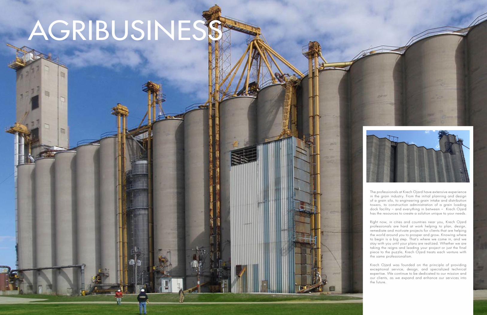
The professionals at Krech Ojard have extensive experience in the grain industry. From the initial planning and design of a grain silo, to engineering grain intake and distribution towers, to construction administration of a grain loading dock facility – and everything in between – Krech Ojard has the resources to create a solution unique to your needs.
Right now, in cities and countries near you, Krech Ojard professionals are hard at work helping to plan, design, remediate and motivate projects for clients that are helping the world around you to prosper and grow. Knowing where to begin is a big step. That’s where we come in, and we stay with you until your plans are realized. Whether we are taking the reigns and leading your project or just the final piece to the puzzle, Krech Ojard treats each venture with the same professionalism.
Krech Ojard was founded on the principle of providing exceptional service, design, and specialized technical expertise. We continue to be dedicated to our mission and our clients, as we expand and enhance our services into the future.
RIVER TERMINAL SITE MASTER PLANNINGMinnesota
The client retained Krech Ojard engineers to develop a master site plan and produce visual graphics to support stakeholder engagement and the permit ting processes. The site handles multiple bulk commodities (scrap steel, salt, fertilizer, & aggregate) across multiple transportation streams (river barge, truck & rail). The facility is located along the Mississippi River in Minnesota. The client placed high priority on the existing handling of fertilizer, scrap steel, salt, and aggregate while respecting future rail developments, environmental constraints and existing facility structures. Plans for the rehabilitation of the bulkhead wall on the Mississippi River is a key element that is vital to site functionality.
ELEVATOR BARGE TERMINALMinnesota
Krech Ojard engineers provided marine and civil engineering for the client’s proposed new elevator barge terminal on the Mississippi River in Minnesota. Provided topographic survey, multiple concept designs, also including configuration, permit planning, costing, and waterway bathymetry. Aerial drone data collection was procured and coordinated with land based markers and model concepts.
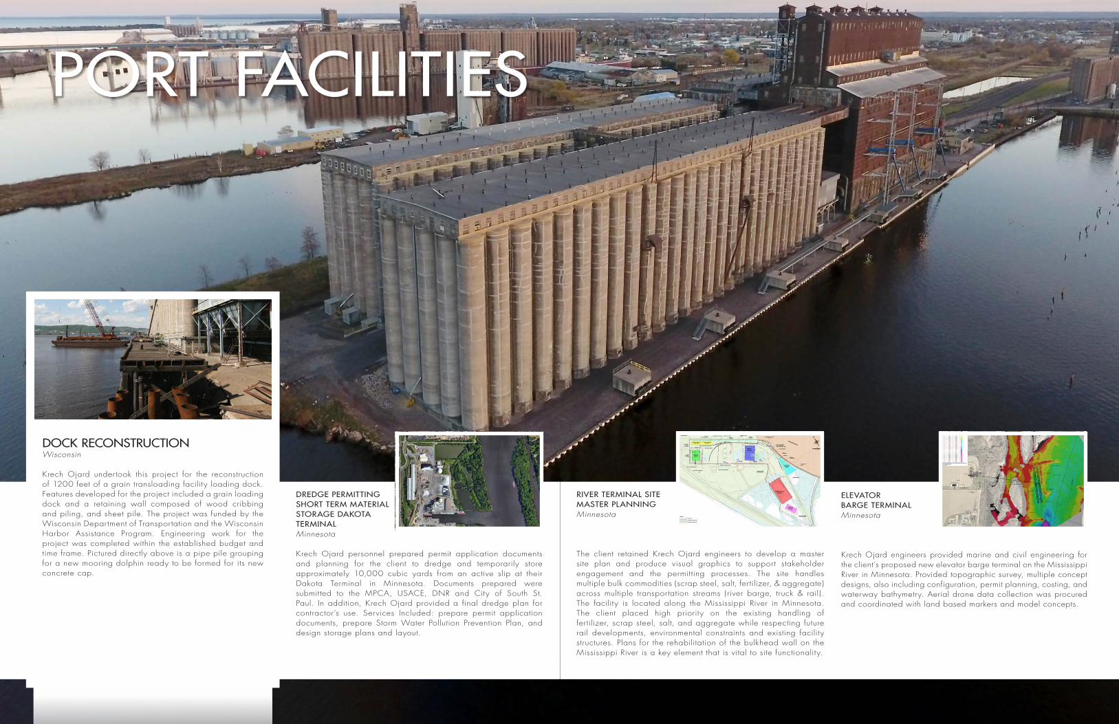
DOCK RECONSTRUCTIONWisconsin
Krech Ojard undertook this project for the reconstruction of 1200 feet of a grain transloading facility loading dock. Features developed for the project included a grain loading dock and a retaining wall composed of wood cribbing and piling, and sheet pile. The project was funded by the Wisconsin Department of Transportation and the Wisconsin Harbor Assistance Program. Engineering work for the project was completed within the established budget and time frame. Pictured directly above is a pipe pile grouping for a new mooring dolphin ready to be formed for its new concrete cap.
PORT FACILITIES
DREDGE PERMITTING SHORT TERM MATERIAL STORAGE DAKOTA TERMINAL Minnesota
Krech Ojard personnel prepared permit application documents and planning for the client to dredge and temporarily store approximately 10,000 cubic yards from an active slip at their Dakota Terminal in Minnesota. Documents prepared were submit ted to the MPCA, USACE, DNR and City of South St. Paul. In addition, Krech Ojard provided a final dredge plan for contractor’s use. Services Included: prepare permit application documents, prepare Storm Water Pollution Prevention Plan, and design storage plans and layout.
GRAIN INTAKE & DISTRIBUTION TOWERSVietnam
Designed 110’ grain intake and distribution towers for supporting mass scales, distribution heads, conveyor head and tail sections, and sorting screens to support ship unloading. Design was accomplished using JIS metric standards and materials and included vibration analysis. Preliminary design reactions of both towers and truss bent reactions were provided to accommodate early fabrication of concrete piles. Also designed a truss supported 150m long tripper conveyor with integral shuttling cross conveyor designed to fill 96m wide bulk storage bays with various grain commodities. Created fully integrated 3D models of the conveyor to simultaneously resolve interferences, create fabrication drawings and part take offs.
BELT UPGRADE & PLATFORMWisconsin
Krech Ojard was engaged by the client to perform a preliminary analysis of an existing conveyor. The project’s scope extended to providing design for a new landing platform and other reinforcements, and included conceptual modeling and 3D laser scanning services to check interferences with existing structures before construction. Scope of services provided included: review existing archive drawings, provide schematic level analysis of floor, truss, roof and towers to determine available capacity for replacing existing belt conveyors and trippers with similar covered conveyors or drag conveyors, and met with staff to confirm operational requirements for loading rates, E/W belt splits and N/S garner splits.
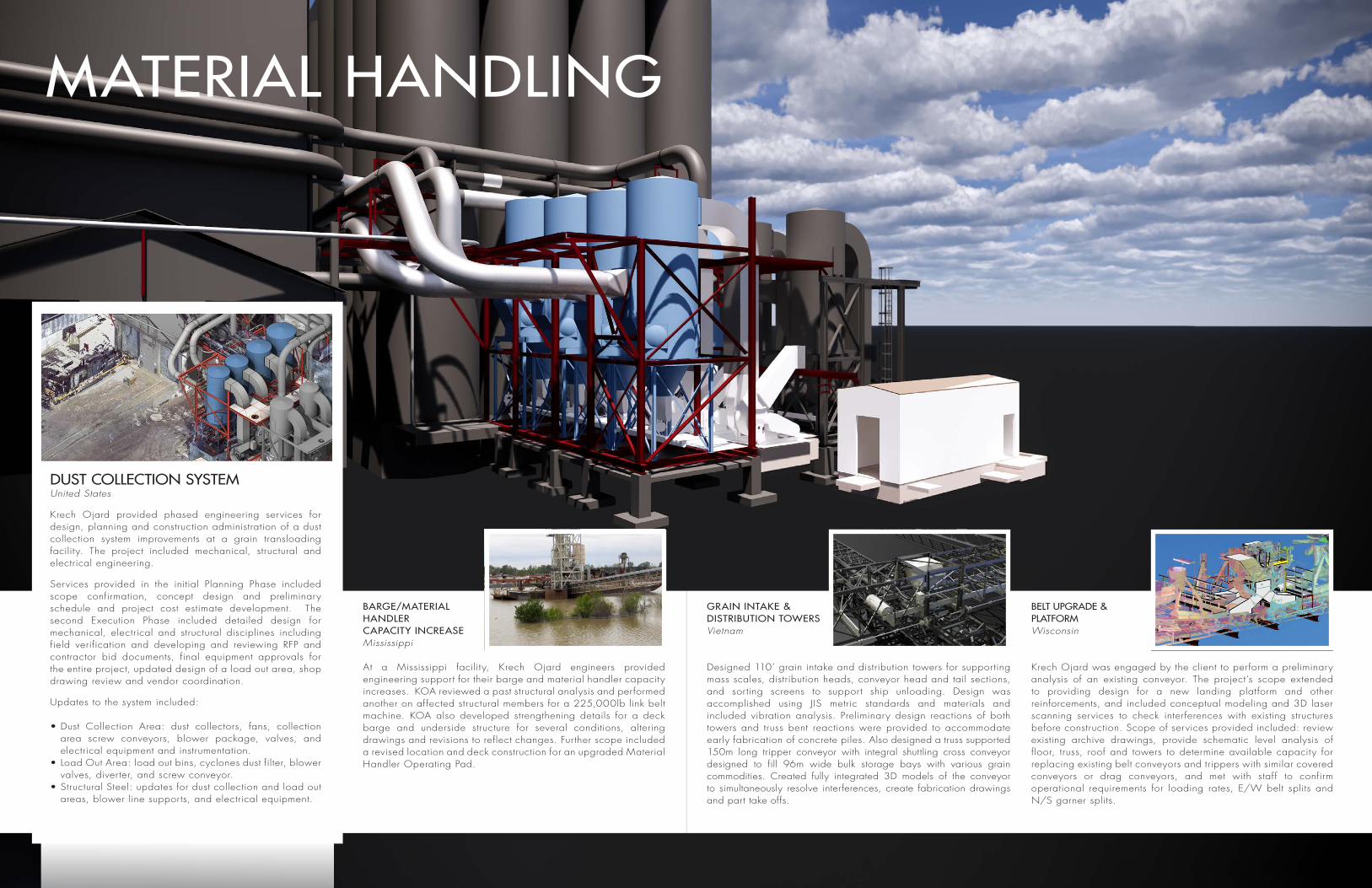
MATERIAL HANDLING
BARGE/MATERIAL HANDLERCAPACITY INCREASEMississippi
At a Mississippi facility, Krech Ojard engineers provided engineering support for their barge and material handler capacity increases. KOA reviewed a past structural analysis and performed another on affected structural members for a 225,000lb link belt machine. KOA also developed strengthening details for a deck barge and underside structure for several conditions, altering drawings and revisions to reflect changes. Further scope included a revised location and deck construction for an upgraded Material Handler Operating Pad.
DUST COLLECTION SYSTEMUnited States
Krech Ojard provided phased engineering services for design, planning and construction administration of a dust collection system improvements at a grain transloading facility. The project included mechanical, structural and electrical engineering.
Services provided in the initial Planning Phase included scope confirmation, concept design and preliminary schedule and project cost estimate development. The second Execution Phase included detailed design for mechanical, electrical and structural disciplines including field verification and developing and reviewing RFP and contractor bid documents, final equipment approvals for the entire project, updated design of a load out area, shop drawing review and vendor coordination.
Updates to the system included:
• Dust Collection Area: dust collectors, fans, collection area screw conveyors, blower package, valves, and electrical equipment and instrumentation.
• Load Out Area: load out bins, cyclones dust filter, blower valves, diverter, and screw conveyor.
• Structural Steel: updates for dust collection and load out areas, blower line supports, and electrical equipment.
Facility scans can be collected at safe distances and critical areas reached afterwards in processing
Measurements easily accessible from any location
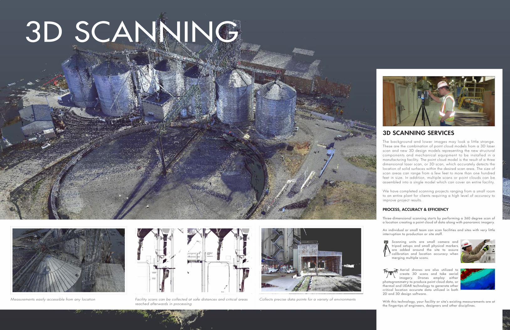
3D SCANNING
3D SCANNING SERVICESThe background and lower images may look a lit t le strange. These are the combination of point cloud models from a 3D laser scan and new 3D design models representing the new structural components and mechanical equipment to be installed in a manufacturing facility. The point cloud model is the result of a three dimensional laser scan, or 3D scan, which accurately detects the location of solid surfaces within the desired scan area. The size of scan areas can range from a few feet to more than one hundred feet in size. In addition, multiple scans or point clouds can be assembled into a single model which can cover an entire facility. We have completed scanning projects ranging from a small room to an entire plant for clients requiring a high level of accuracy to improve project results.
PROCESS, ACCURACY & EFFICIENCY
Three-dimensional scanning starts by performing a 360 degree scan of a location creating a point cloud of data along with panoramic imagery.
An individual or small team can scan facilities and sites with very lit tle interruption to production or site staff.
Scanning units are small camera and tripod setups and small physical markers are added around the site to assure calibration and location accuracy when merging multiple scans.
Aerial drones are also utilized to create 3D scans and take aerial imagery. Drones employ either
photogrammetry to produce point cloud data, or thermal and LIDAR technology to generate other critical location accurate data utilized in both 2D and 3D design software.
With this technology, your facility or site’s existing measurements are at the fingertips of engineers, designers and other disciplines.
Collects precise data points for a variety of environments

Visualize interior structure of a confined tank spaceModeled to fit existing facility space
3D point cloud elevation
POINT CLOUDS
USE OF POINT CLOUDS
Utilizing the 3D laser scanner, engineers can safely and accurately gather massive amounts of data. 3D laser scanning and surveys of facilities while they are in service are becoming more common. The surveys allow engineers to quickly develop preventive maintenance plans, create analysis reports, and analyze a space to make sure that a piece of equipment will fit into that space. Another use of the 3D laser scanning is to monitor defects in a structure and create a plan to stabilize the structure, saving costs and a potential catastrophe. Aging, deformation, and movement are inevitable. 3D laser scanning is the most cost-effective tool to monitor large structures and lower remediation costs.
Engineers use point cloud data as a tool to create as-built drawings instead of taking hand measurements and manually drawing the entire project. Point clouds provide a single and accurate set of measurements that improve design as well as communication among building owners, designers and contractors. They offer value by providing a single set of information that can easily be shared with the entire design team.
This technology presents Krech Ojard staff members with unprecedented opportunities to improve design accuracy through the ability to access vir tually unlimited data concerning existing conditions at our client’s facilities when compared to the normal workflow of design and verification at sites that are miles away from the location that the work is being performed. As one of our designers puts it “It’s as if we scooped up the site and brought it back to the office to work on.” Scanning activities can be performed in both indoor and outdoor environments and can allow for digital walkthroughs of facilities. Scans of above and below ground level are combined to offer unique visuals and locations of buried structures.
Point clouds and models can be viewed from multiple angles

BARGE LOADING DOCK REPAIR Louisiana
Krech Ojard was retained to assess and redesign barge loading docks at a Louisiana facility that had been destroyed by weather. The project included underwater marine investigations of the damage, an erosion study, design options for both repair or replacement of dock system, design of upgrades to material handling conveyor systems, preparation of construction documents, and engineering support during construction of: 4 driven pile mooring dolphins, 300’ cast-in-place concrete industrial dock, 100’ conveyor dock, 17yd feed hopper, and a 36” wide x 100’ conveyor. All new dock structures were designed to be founded on driven steel pipe piles. Krech Ojard also handled coordination with both the city port and the USACE.
BARGE FLEETING & PERMIT SUPPORTIllinois
The client engaged Krech Ojard to provide barge fleeting permit support for their coal terminal located along the Mississippi River in Illinois. The permitting process included two phases, the transfer of the terminal’s original barge fleeting permit to the client and the development of expanded fleeting areas to support barge fleeting for a nearby grain handling facility. Scope included: GIS data acquisition and compilation including: aerial photography, USACE virtual charts, and historical Automatic Identification System (AIS), development of barge fleeting layouts for four fleeting areas and the terminal dock for two river level scenarios, comparison of historic vessel traffic to proposed expanded fleeting areas with AIS data, and virtual fleet data creation used by USACE within in their GIS applications and for public notifications.
RIVER TERMINAL Illinois
Worked with Baird to support the client’s effort in developing a new transloading facility for grain along the Mississippi River in Illinois. KOA provided permitting support as well as engineering development from concepts to detailed design, to construction documents. Scope included: widening of existing levy to accommodate expanded truck haul road, design of new mooring cells and dolphins and cable indexer for barge handling, design of conveyors for loading of four barge strings, and mooring at barge fleeting area was located down river from loading points. Krech Ojard worked closely with the Engineering Project Team and entities such as United State Army Corp of Engineers (USACE), the Illinois Department of Natural Resources, and the Illinois Environmental Protection Agency to secure the required approval and permits.
TRANSSHIPMENT
DOCK RECONSTRUCTIONWisconsin
Responsible for the reconstruction of 1150 feet of the a grain transloading facility loading dock in Wisconsin. The reconstruction of project was completed in two phases. The first phase involved the 600 foot of dock, and the second phase was completed two years later. Features in this project included construction of concrete dock supported on wood piles, a 160 foot high grain storage silo’s along dock face, and 1150 feet of steel sheet pile bulkhead. Special issues the Krech Ojard needed to address were loss of lateral support to silo mat piling and soil instability on and around dock.

RAIL LOADOUT AND SCHEMATIC MODELING SUPPORTTexas
Krech Ojard provided engineering support for a client at their Texas facility. This project centered on rail loadout/unloading systems and upgrades within the system. Utilizing 3D scans of the facility created in previous projects, designs for the upgraded hopper, supports and rail loading spouts were referenced and verified within point cloud modeling for accuracy. Scope included: engineering support for installation and structural support of a new rail hopper, design of hopper support beams, connections to concrete walls, and rail loading spout - general arrangement and supports design.
RAIL YARD EXPANSIONWisconsin
Krech Ojard completed a study with alternates for expansion of rail yard to accept unit train shipments, analyzed track configuration to minimize switching during unloading operations, design provided for phased construction as to not reduce facility capacity during construction, filed and coordinated Exceptions to Standards with BNSF and the Office of Commissioner of Railroads, and prepared plans and specs for competitive bidding.
RAILROAD
RAIL LOOPS & TRANSLOAD FACILITYNorth Dakota
Working with a large regional rail contractor which is the prime on this new rail loop and transload facility, Krech Ojard is supplying construction administration and construction management services for a confidential energy client in North Dakota.
The facility will first transfer oil from truck to train via a short Y track and phase two will transfer oil direct from tanks through an underground pipeline to trains on a double line rail loop.
CONSTRUCTION DIRECTIVES/FEATURES• Construct a two phase oil transload facility
» Phase 1 - Truck to Rail (10,000 bpd) 1-train/week » Phase 2 - Direct Storage Tank to Rail (80,000bpd) » Phase 1 - 10,000ft of siding and track extensions » Phase 2 - Double CWR rail loop with 900’ and an 18 station loading rack - 30,000ft
» Constructed on steel ties with 1600’ of continuous welded rail (CWR)
» Imported 80,000NT ballast & sub-ballast via 10 unit trains
» On-site aggregate handling facility constructed specifically for the project
• Constructed off of a BNSF served facility, Berthold Farmers Elevator (BFE), around congested operations coordinating both agricultural elevator, shuttle trains, unit trains of oil cars from fill loading, and unit trains of project aggregate.
• Coordination with BNSF for passing siding construction and tie-in, including grade preparation for siding extension. Signal pad construction, facility operations planning/coordination for service outages and loss of west end train access for BNSF related infrastructure installations.
RAILROADBRIDGE INSPECTIONNebraska
Inspected the physical condition of a 192ft, nine-span rail bridge structure located on a grain facility spur line and spans over the South Table Creek and an abandoned road in southeastern Nebraska. The bridge includes seven spans of timber superstructure and two spans of steel superstructure supported on timber trestles. The rail is supported by an open timber deck, with a walkway on the south side and an extended platform on one span. The purpose of this inspection was to verify the structural integrity of the bridge and to document conditions that affect the bridge’s overall structural integrity. The inspection focused upon visual deformities, cracks, decay, corrosion, signs of movement or displacement, and other signs of distress. The report supplied included recommendations for specific and general repairs, while categorizing the severity or necessity of each as immediate or long term recommendations.

krechojard.com


