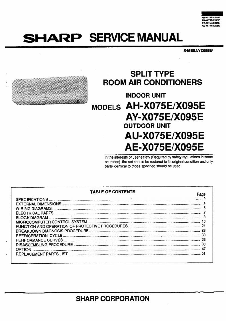
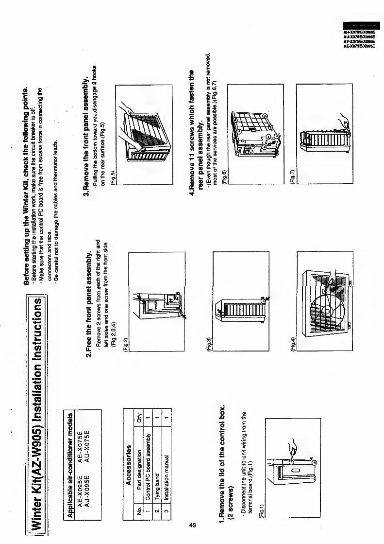
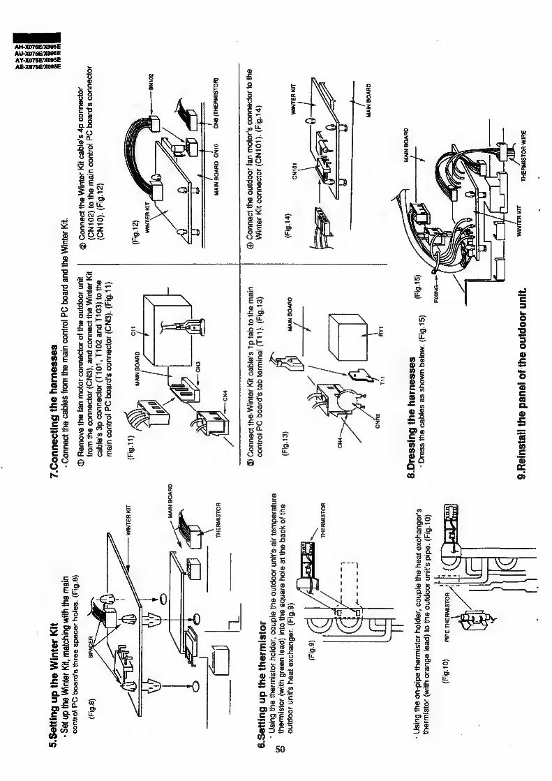
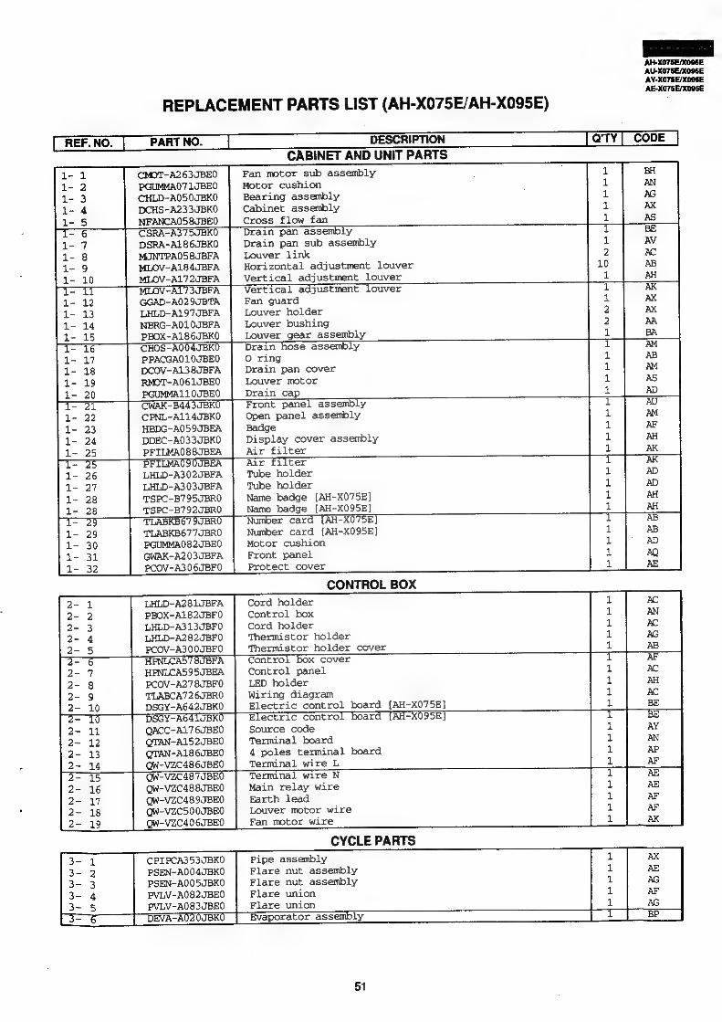
AH-X075E/X095E AE-X075E/X095E SHARP SERVICE MANUAL S45B8AYX095E/ SPLIT TYPE ROOM AIRCONDITIONERS INDOOR UNIT movELs AH-X075E/X095E AY-X075E/X095E OUTDOOR UNIT AU-X075E/X095E AE-X075E/X095E In the interests ofuser-safety (Required by safety regulations in some countries) the set should berestored toitsoriginal condition and only parts identical tothose specified should be used. TABLE OF CONTENTS SPECIFICATIONS EXTERNAL DIMENSIONS WIRING DIAGRAMS ELECTRICAL PARTS BLOCK DIAGRAM MICROCOMPUTER CONTROL SYSTEM FUNCTION AND OPERATION OF PROTECTIVE PROCEDURES BREAKDOWN DIAGNOSIS PROCEDURE REFRIGERATION CYCLE PERFORMANCE CURVES DISASSEMBLING PROCEDURE REPIZACEMENT PARTo LIST eciptssts exscxsesactsnscustedecdav ec ttovisacnsuatboumpansicaoseustactanasieiGanseakcus audineabassunionts iebtaatuaetle reas .51 SHARP CORPORATION
Transcript
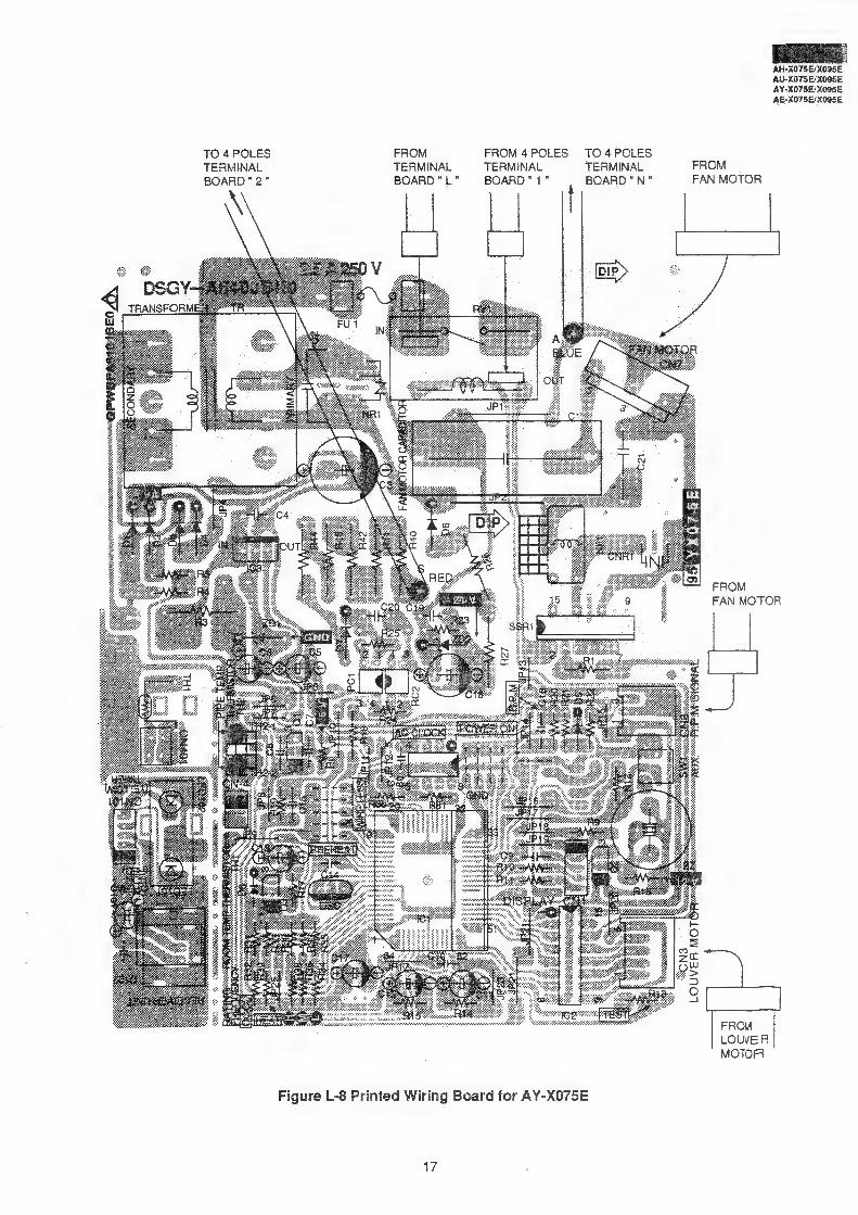
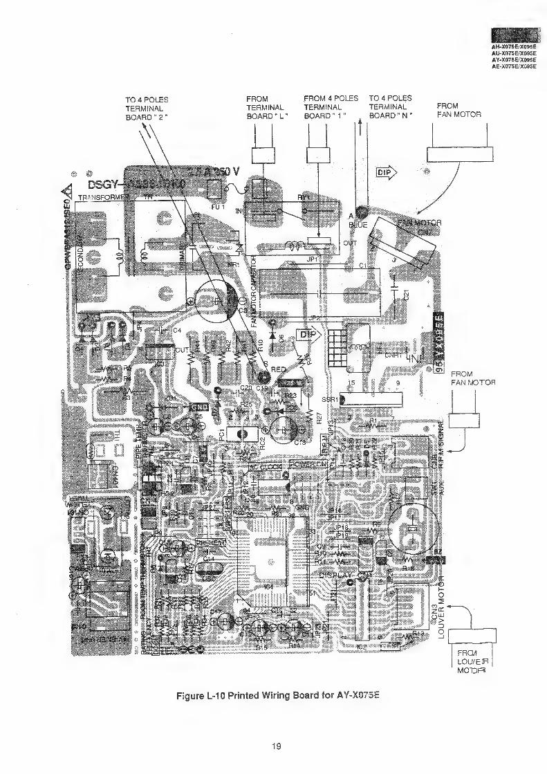
AH-X075E/X095E
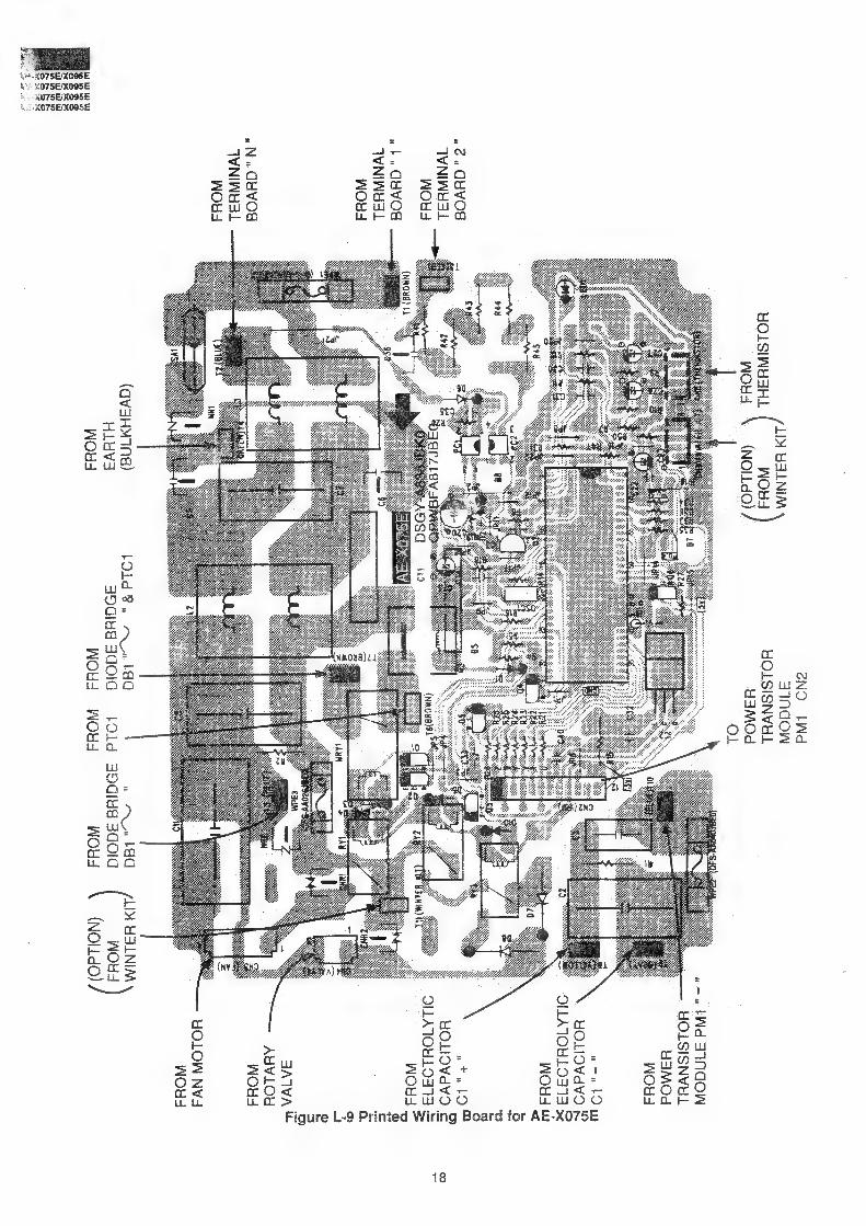
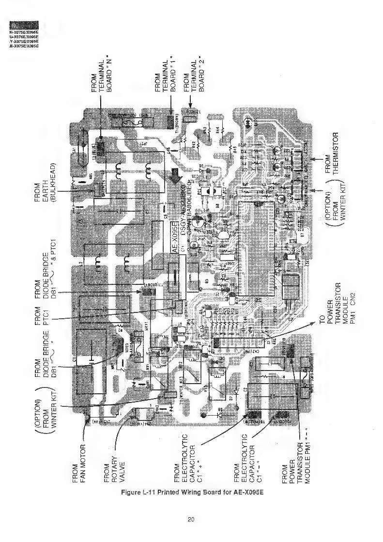
AE-X075E/X095E
SHARP SERVICE MANUAL S45B8AYX095E/
SPLIT TYPE ROOM AIR CONDITIONERS
INDOOR UNIT
movELs AH-X075E/X095E AY-X075E/X095E OUTDOOR UNIT
AU-X075E/X095E AE-X075E/X095E
In the interests of user-safety (Required by safety regulations in some
countries) the set should be restored to its original condition and only parts identical to those specified should be used.
TABLE OF CONTENTS
SPECIFICATIONS EXTERNAL DIMENSIONS WIRING DIAGRAMS ELECTRICAL PARTS BLOCK DIAGRAM MICROCOMPUTER CONTROL SYSTEM FUNCTION AND OPERATION OF PROTECTIVE PROCEDURES BREAKDOWN DIAGNOSIS PROCEDURE REFRIGERATION CYCLE PERFORMANCE CURVES DISASSEMBLING PROCEDURE
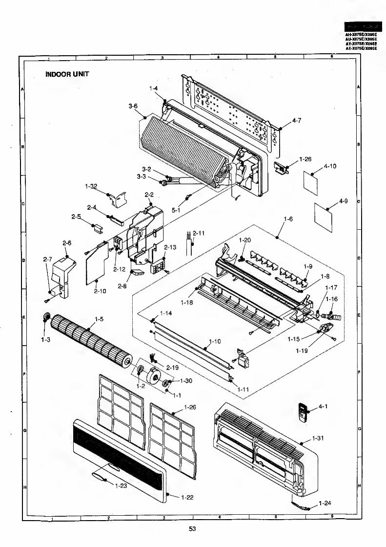
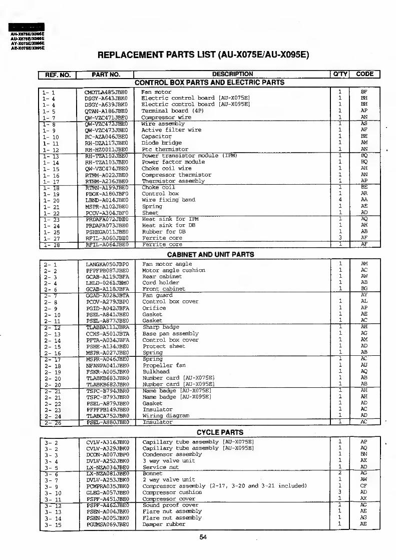
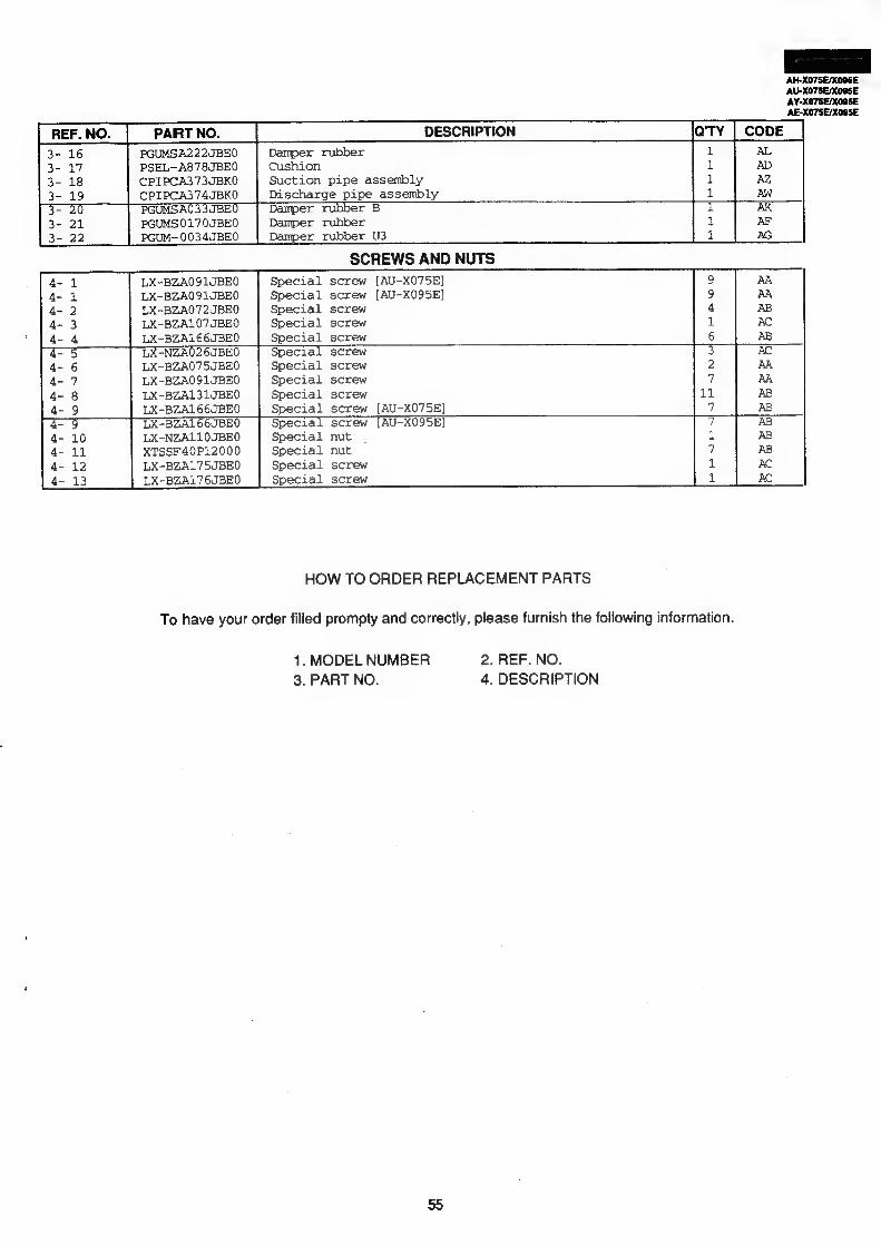
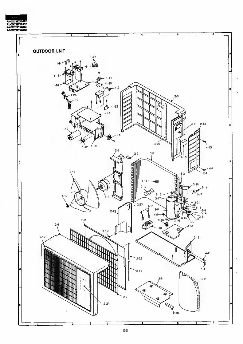
REPIZACEMENT PAR To LIST eciptssts exscxsesactsnscustedecdav ec ttovisacnsuatboumpansicaoseustactanasieiGanseakcus audineabassunionts iebtaatuaetle reas .51
SHARP CORPORATION
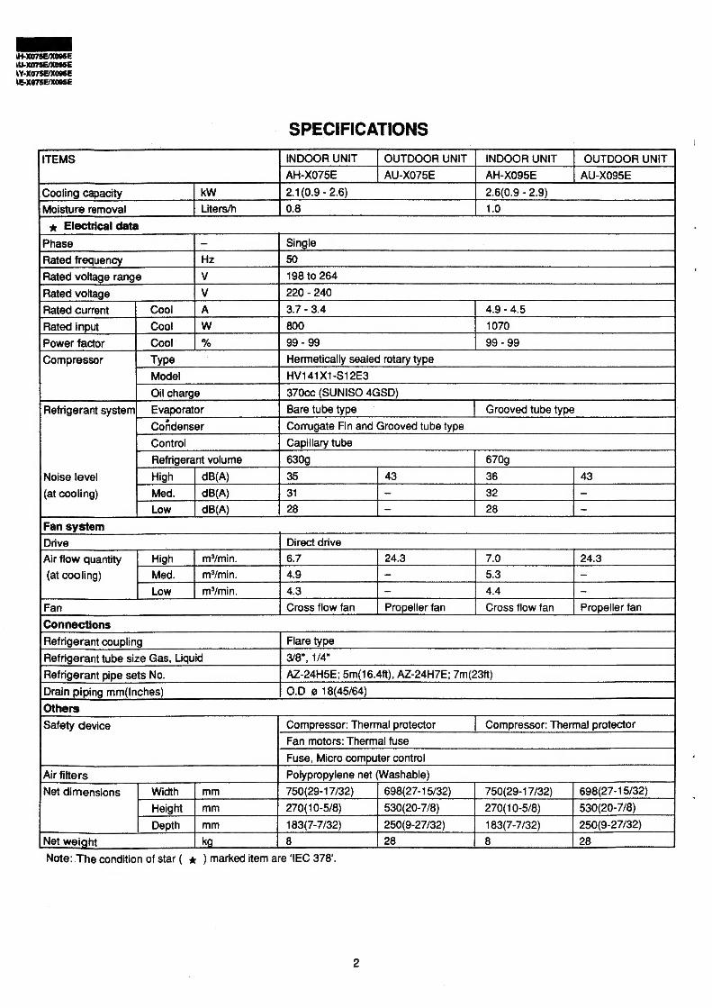
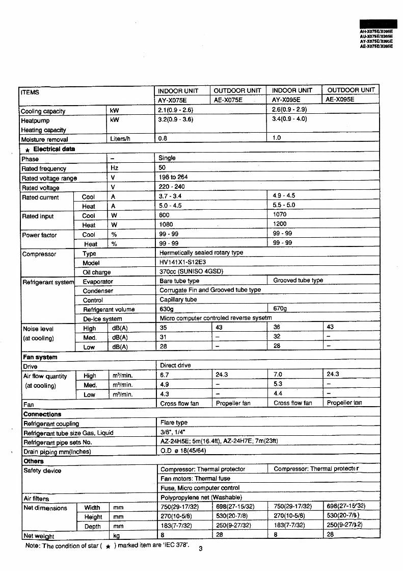
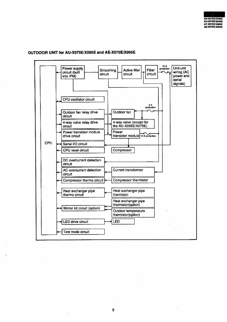
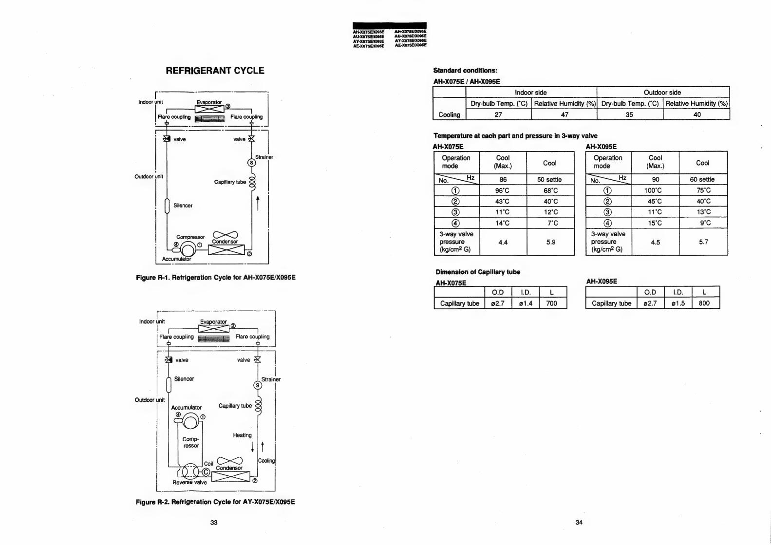
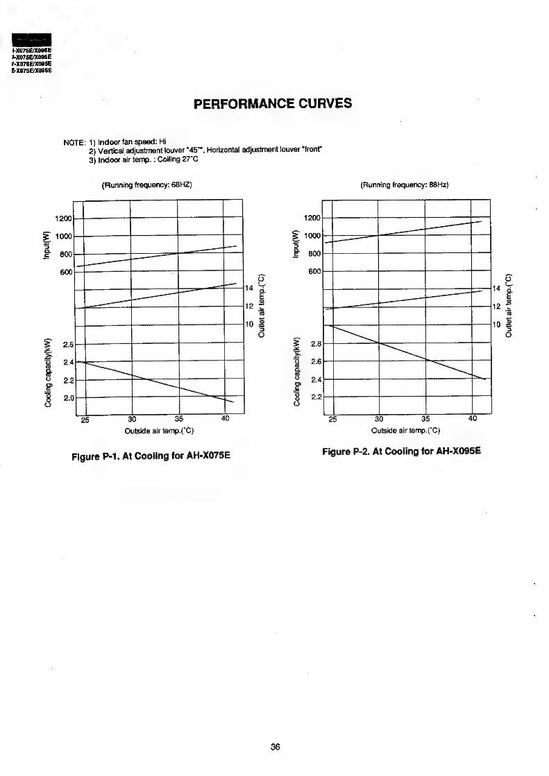
SPECIFICATIONS
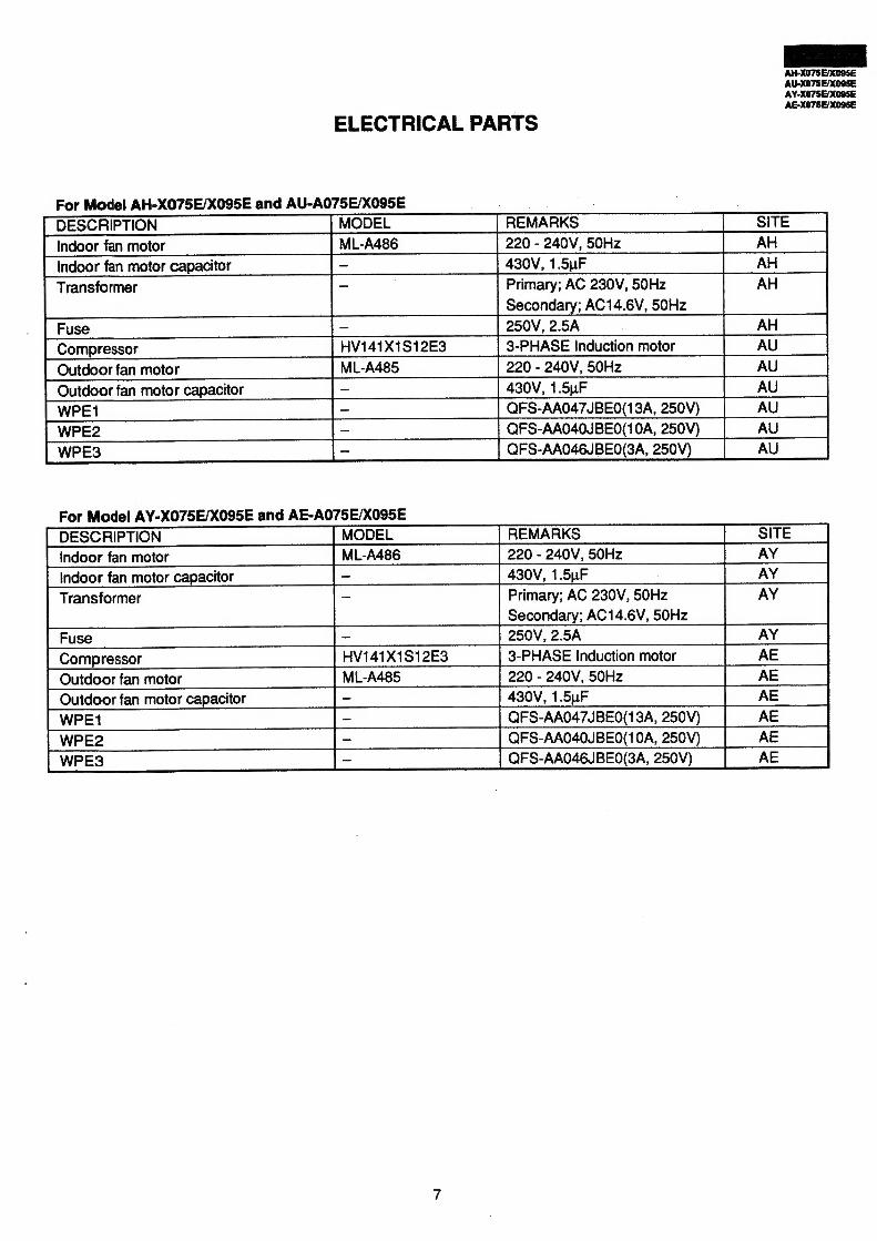
OUTDOOR UNIT | INDOOR UNIT | OUTDOOR UNIT AH-XO95E AU-X095E
[Cooling capacity sss | KW Cd 10.9-26) = ss CSCCC*ds«2.8(.)- 2.9) [Moisture removal ssf Liters f8 (C(t: OC“‘“CSCOC*C*#*#C#C#C*C‘*dC
= V141X1-S12E3
Oil charge 70cc (SUNISO 4GSD)
Refrigerant system| Evaporator Grooved tube type
Condenser orrugate Fin and Grooved tube type
Control apillary tube
Refrigerant volume
x Electrical data
Phase Single Ratedfrequency = [Hz TSO
37-34 Page [Ratedinput || Cool |W __—|_ 800
% 99 - 99 Hermetically sealed rotary type
wo
oO
fe)
=|
iil
wo
g & Noise level | Hign [opa) = [35 Cid Cl (Cd CC (at cooling) | Med. | oea) fst CK t—“‘<‘i CK
AH-X075E/XO95E are not provided with the b. heating function.
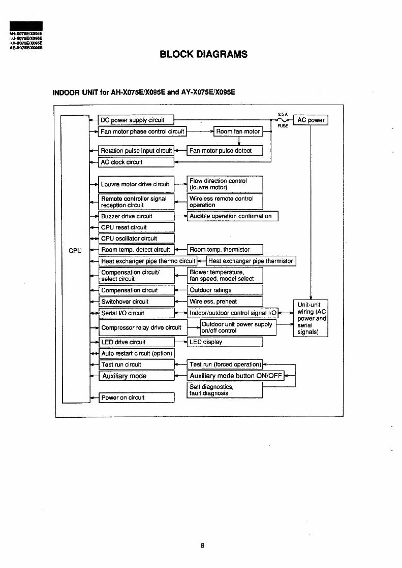
1. INDOOR UNIT 1-1 Temperature Adjustment
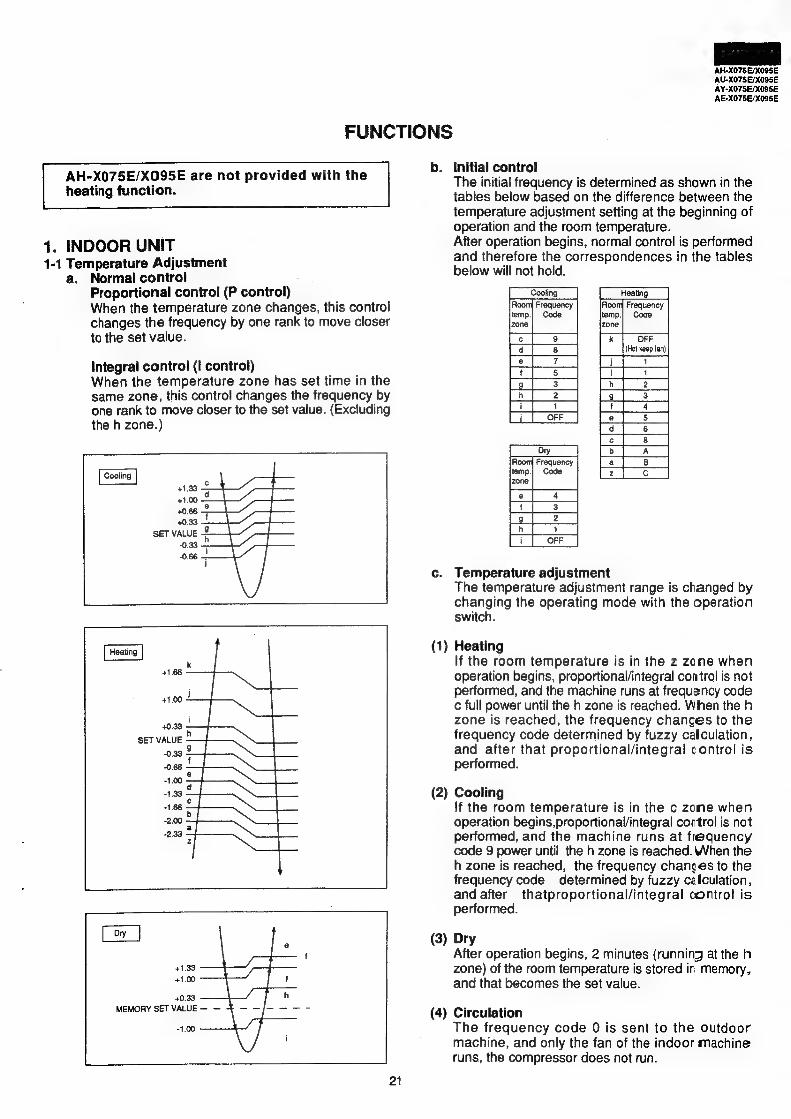
a. Normal control Proportional control (P control) When the temperature zone changes, this control changes the frequency by one rank to move closer to the set value.
integral control (I control) When the temperature zone has set time in the same zone, this control changes the frequency by one rank to move closer to the set value. (Excluding the h zone.)
+133
+1.00
SET VALUE
0.33 ~ ~0.66 j
+1.33
+1.00
+0.33
MEMORY SET VALUE — —
-1.00
Initial control The initial frequency is determined as shown in the tables below based on the difference between the temperature adjustment setting at the beginning of operation and the room temperature. After operation begins, normal control is performed and therefore the correspondences in the tables below will not hold.
[Seating Frequency Frewery
ak Code Code zone
ze a ae 7 ee ee Te aa a fo | 3 | Pht 2 | i ied [ i | OFF |
Room Frequency
temp.| Code zone
c. Temperature adjustment The temperature adjustment range is changed by changing the operating mode with the operation switch.
(1) Heating If the room temperature is in the z zone when operation begins, proportional/integral control is not performed, and the machine runs at frequency code c full power until the h zone is reached. When the h zone is reached, the frequency changes to the frequency code determined by fuzzy calculation, and after that proportional/integral control is performed.
(2) Cooling If the room temperature is in the c zone when operation begins,proportional/integral control is not performed, and the machine runs at fiequency code 9 power until the h zone is reached. When the h zone is reached, the frequency changes to the frequency code determined by fuzzy cafculation, and after thatproportional/integral control is performed.
(3) Dry After operation begins, 2 minutes (running at the h zone) of the room temperature is stored in memory, and that becomes the set value.
(4) Circulation The frequency code 0 is sent to the outdoor machine, and only the fan of the indoor machine runs, the compressor does not run.
U-XO75E/X095E
1¥-X075E/X005E iE-X075E/X005E
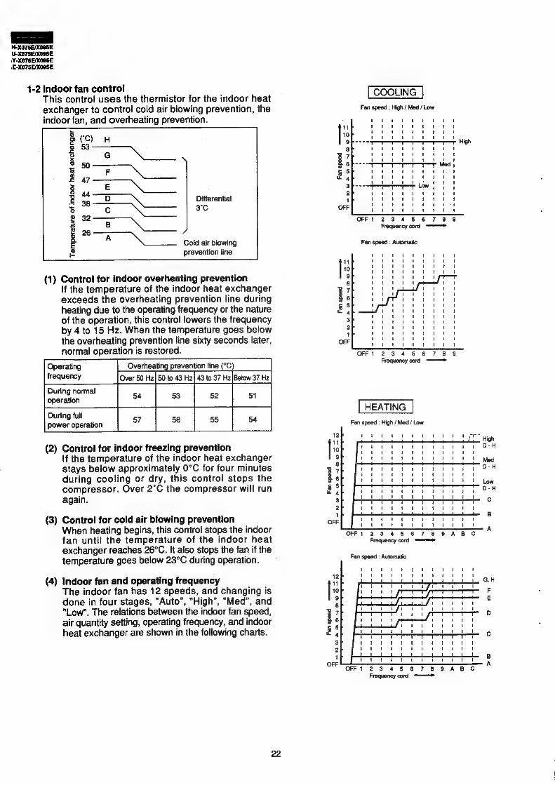
1-2 indoor fan control [COOLING |
This control uses the thermistor for the indoor heat COOLING
exchanger to control cold air blowing prevention, the Fan speed : High / Med / Low
indoor fan, and overheating prevention. fr
Differential
3°C T]@NWAOADANDWAOO — 9 A
ol ------ ee eee
Cold air biowing Fan speed : Automatic
prevention line
2 ro s S 4 o 3 ® £
3 3G & ead 3 2 2 « ® Q
5 fim
oe
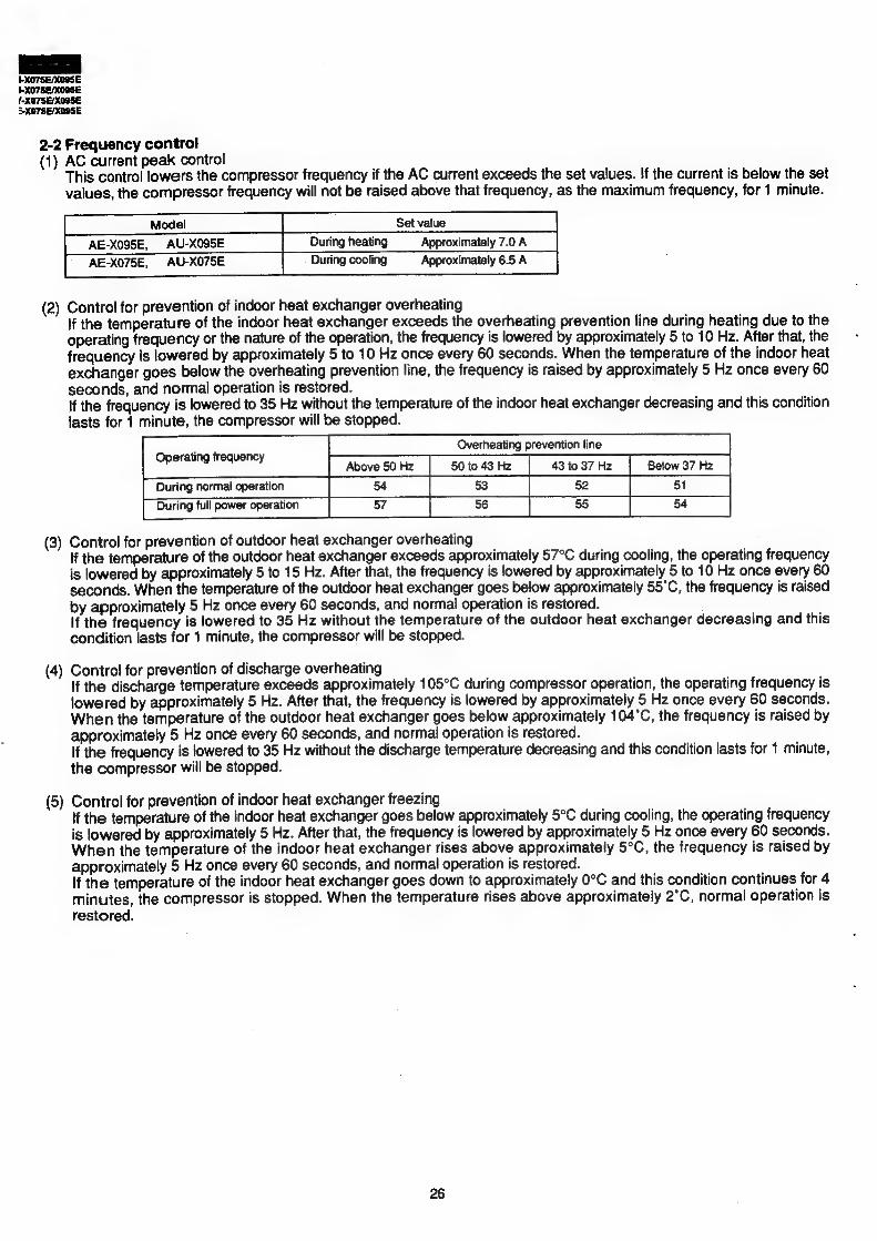
(1) Control for indoor overheating prevention If the temperature of the indoor heat exchanger exceeds the overheating prevention line during heating due to the operating frequency or the nature of the operation, this contro! lowers the frequency by 4 to 15 Hz. When the temperature goes below the overheating prevention line sixty seconds later, normal operation is restored. os
Operating Overheating prevention line (°C)
frequency | Over 50 Hz| 50 to 43 Hz | 43 to 37 Hz|Below 37 Hz During normal
Ghee sf eee Sas bots ee Scene hoa ss Ph are fae ane |
1 ' I
1
1 \ 1
1
1
i}
' !
t
t
‘
t
3 qui
1 1 1 ! 1 1 1 ' l
I ' i}
!
\ '
I
2 Fi
Fan speed : High / Med/ Low
8 2
12
(2) Control for indoor freezing prevention [ie If the temperature of the indoor heat exchanger 3 stays below approximately 0°C for four minutes B ; during cooling or dry, this control stops the a6
compressor. Over 2°C the compressor will run Bs again. 3
2
(3) Control for cold air blowing prevention oe When heating begins, this control stops the indoor fan until the temperature of the indoor heat exchanger reaches 26°C. It also stops the fan if the temperature goes below 23°C during operation.
(4) Indoor fan and operating frequency 7 The indoor fan has 12 speeds, and changing is [io done in four stages, "Auto", "High", "Med", and "Low". The relations between the indoor fan speed, 3 7 air quantity setting, operating frequency, and indoor g 6 heat exchanger are shown in the following charts. a
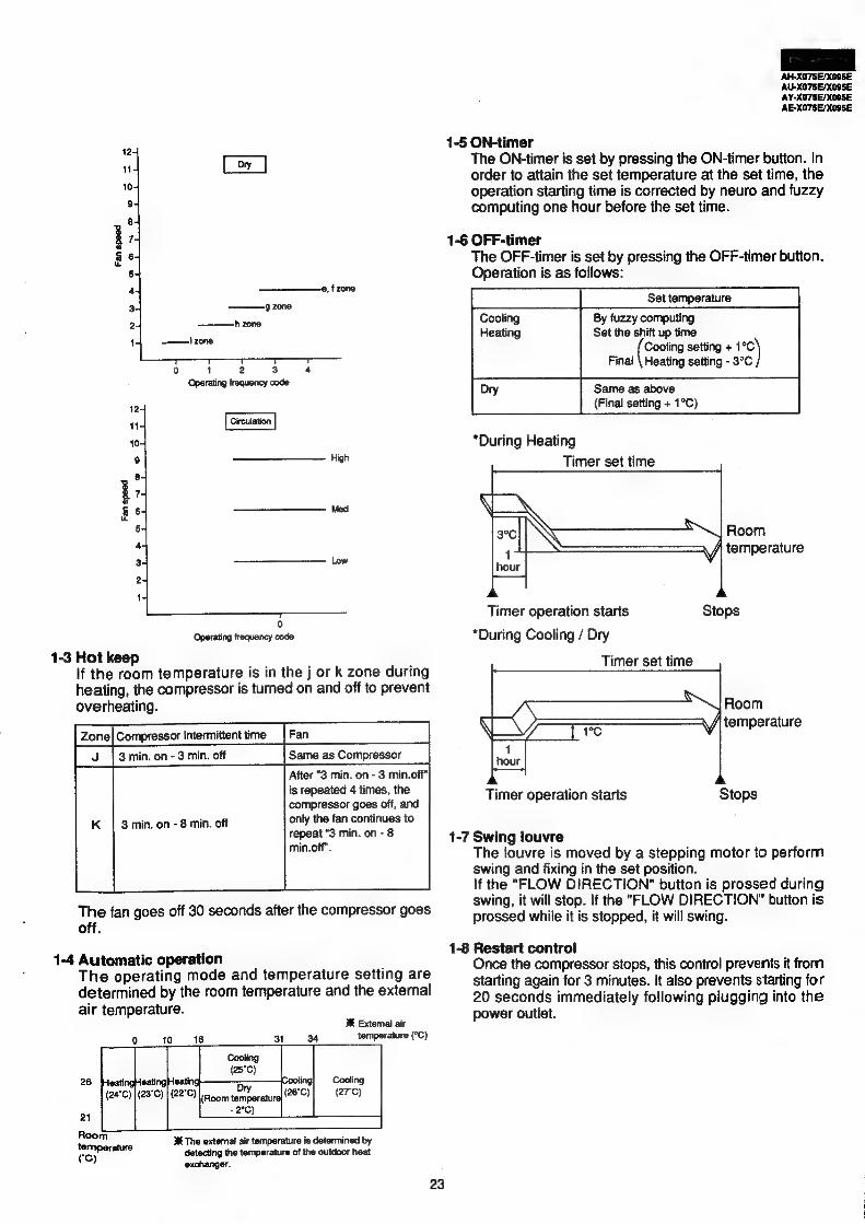
1-3 Hot keep : If the room temperature is in the j or k zone during
heating, the compressor is turned on and off to prevent overheating.
Fs [amin on-8min of [Same as Compressor | After "3 min. on - 3 min.off"
is repeated 4 times, the compressor goes off, and only the fan continues to repeat “3 min. on - 8
min.off”.
3 min. on - 8 min. off
The fan goes off 30 seconds after the compressor goes off.
1-4 Automatic operation The operating mode and temperature setting are determined by the room temperature and the external air temperature.
MR Extemal air temperature (°C)
0 10 18 31 34
Cooling
(25°C) 26 HeatingHeatingHeating Dy ooling Cooling
(24°C) | (23°C) | (22°C) (26°C) (27°C)
-2°C 21 eS)
Heald stun 3% The external air temperature is determined by (oy erate detecting the temperature of the outdoor heat
exchanger.
23
The ON-timer is set by pressing the ON-timer button. In order to attain the set temperature at the set time, the operation starting time is corrected by neuro and fuzzy computing one hour before the set time.
1-6 OFF-timer The OFF-timer is set by pressing the OFF-timer button. Operation is as follows:
ae Set temperature Cooling By fuzzy computing Heating Set the shift up time
( Cooling setting + ng Final \ Heating setting - 3°C
Dry Same as above (Final setting + 1°C)
*During Heating
Timer set time
NA
— Room \/) temperature
Stops Timer operation starts
*During Cooling / Dry
Timer set time
EEN eon QF eter 1
Stops Timer operation starts
1-7 Swing louvre The louvre is moved by a stepping motor to perform swing and fixing in the set position. If the "FLOW DIRECTION" button is prossed during swing, it will stop. If the "FLOW DIRECTION" button is prossed while it is stopped, it will swing.
1-8 Restart control Once the compressor stops, this contro! prevents it from starting again for 3 minutes. It also prevents starting for 20 seconds immediately following plugging into the power outlet.
*-XO75E/X00SE =X075E/X09SE
1-9
1-10
1-12
1-13
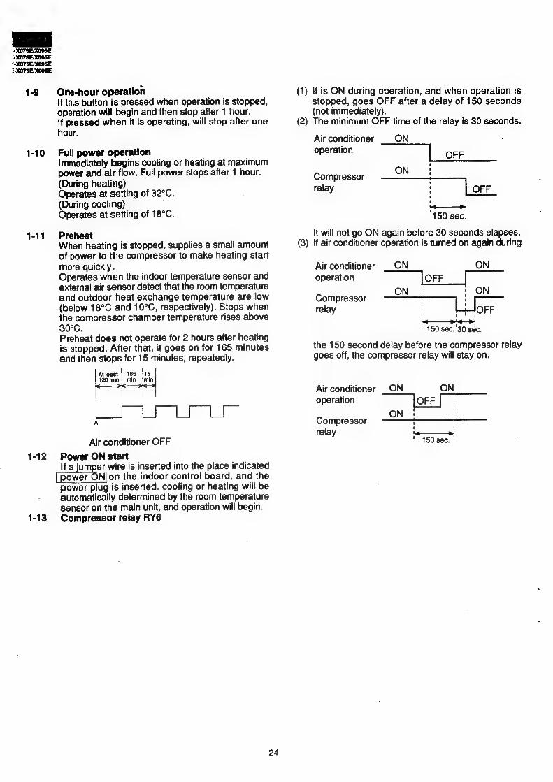
One-hour operation If this button is pressed when operation is stopped, operation will begin and then stop after 1 hour. {f pressed when it is operating, will stop after one hour.
Full power operation Immediately begins cooling or heating at maximum power and air flow. Full power stops after 1 hour. (During heating) Operates at setting of 32°C. (During cooling) Operates at setting of 18°C.
Preheat When heating is stopped, supplies a small amount of power to the compressor to make heating start more quickly. Operates when the indoor temperature sensor and external air sensor detect that the room temperature and outdoor heat exchange temperature are low (below 18°C and 10°C, respectively). Stops when the compressor chamber temperature rises above 30°C. Preheat does not operate for 2 hours after heating is stopped. After that, it goes on for 165 minutes and then stops for 15 minutes, repeatedly.
Atleast | 165 [15 120 min | min jmin
Sod eh del ea
Air conditioner OFF
Power ON start lfa STON wire is inserted into the place indicated
[power ONjon the indoor control board, and the power plug is inserted. cooling or heating will be
automatically determined by the room temperature sensor on the main unit, and operation will begin. Compressor relay RY6
24
(1) It is ON during operation, and when operation is
(2)
(3 —
stopped, goes OFF after a delay of 150 seconds (not immediately). The minimum OFF time of the relay is 30 seconds.
Air conditioner ON operation OFF
Compressor oN
relay | OFF
ri 150 sec.
it will not go ON again before 30 seconds elapses. lf air conditioner operation is turned on again during
ON Air conditioner ON
operation OFF
ON ON
LJ OFF Compressor relay
150 sec. 30 sec.
the 150 second delay before the compressor relay goes off, the compressor relay will stay on.
AU-X075E/X095E are not provided with the heating function.
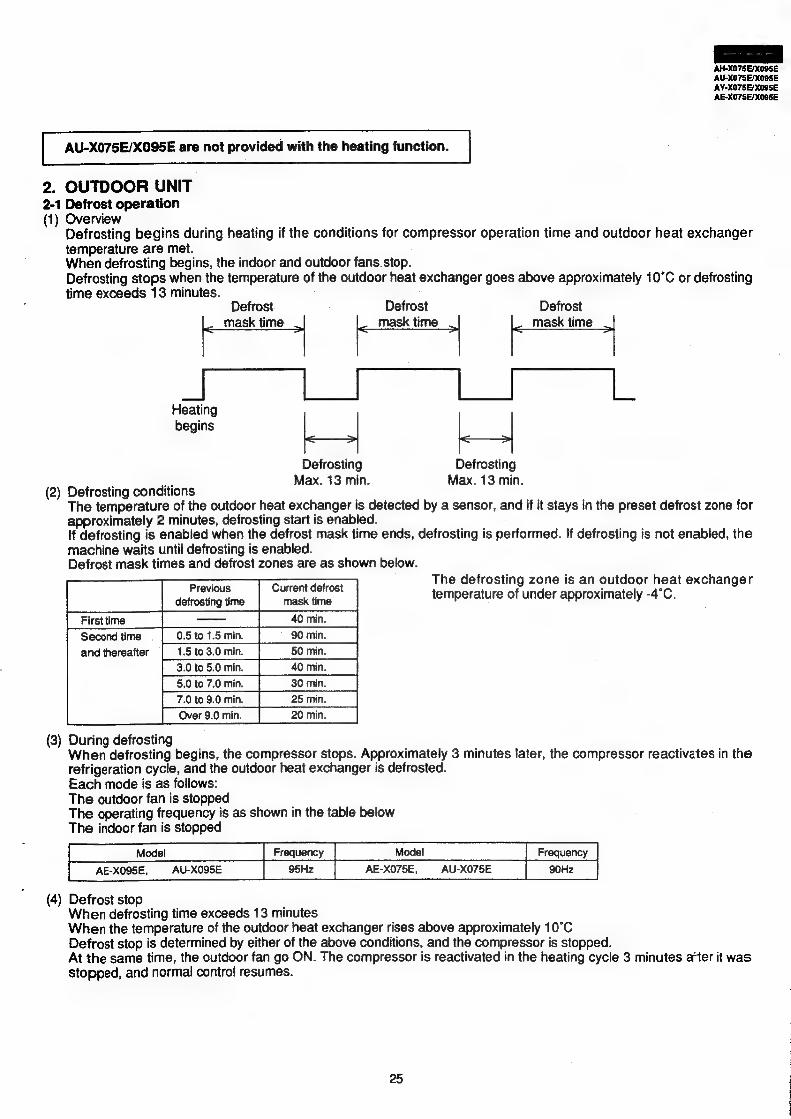
2. OUTDOOR UNIT 2-1 Defrost operation (1) Overview
Defrosting begins during heating if the conditions for compressor operation time and outdoor heat exchanger temperature are met. When defrosting begins, the indoor and outdoor fans stop. Defrosting stops when the temperature of the outdoor heat exchanger goes above approximately 10°C or defrosting time exceeds 13 minutes.
Defrost Defrost Defrost
mask time ‘ i mask time | | mask time |
Heating begins | | | |
Defrosting Defrosting os Max. 13 min. Max. 13 min.
(2) Detrosting conditions The temperature of the outdoor heat exchanger is detected by a sensor, and if it stays in the preset defrost zone for approximately 2 minutes, defrosting start is enabled. If defrosting is enabled when the defrost mask time ends, defrosting is performed. If defrosting is not enabled, the machine waits until defrosting is enabled. Defrost mask times and defrost zones are as shown below.
defrosting time mask time
| Firstime | Second time and thereafter
—
The defrosting zone is an outdoor heat exchanger temperature of under approximately -4°C.
3.01050 min._| 40min. 5.0t07.0min. [| 80min. _| 7.0%09.0 min. | 25min. | Over 9.0 min.
(3) During defrosting When defrosting begins, the compressor stops. Approximately 3 minutes later, the compressor reactivates in the refrigeration cycle, and the outdoor heat exchanger is defrosted. Each mode is as follows: The outdoor fan is stopped The operating frequency is as shown in the table below The indoor fan is stopped
AE-XO95E, AU-X095E | 95Hz | AE-X075E, AU-X075E
Defrost stop When defrosting time exceeds 13 minutes When the temperature of the outdoor heat exchanger rises above approximately 10°C Defrost stop is determined by either of the above conditions, and the compressor is stopped. At the same time, the outdoor fan go ON. The compressor is reactivated in the heating cycle 3 minutes aHer it was Stopped, and normal control resumes.
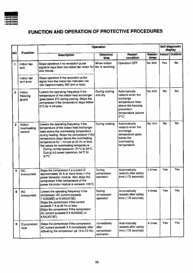
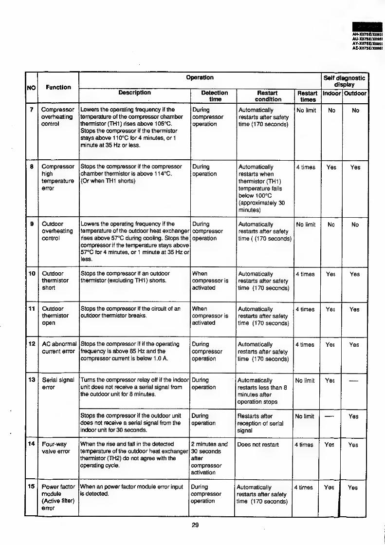
Description Detection Restart Restart Outdoor time condition times
Indoor fan Stops operation if no revolution pulse When indoor Operation OFF Yes
lock signal is input from the indoor fan motor for} fan is revolving
one minute.
Indoor fan Stops operation if the revolution pulse
rpm error signal from the indoor fan indicates low
rpm (approximately 300 rpm or less).
Indoor Lowers the operating frequency if the During cooling | Automatically
freezing temperature of the indoor heat exchanger | and dry restarts when the
exchange temperature rises
above the freezing prevention
temperature (above
2°C)
Automatically No limit il
guard goes below 5°C during cooling. Stops the
restarts when the
7
compressor if the temperature stays below
exchange
;
0°C for 4 minutes.
temperature goes
Lowers the operating frequency if the During heating temperature of the indoor heat exchanger rises above the overheating temperature |} during heating. Stops the compressor if the temperature stays above the overheating
temperature for 1 minute at 35 Hz or less. Set values for overheating temperature
During normal operation: 51°C to 54°C During full power operation: 54°C to
§7°C
Indoor overheating control
below the overheating temperature.
Stops the compressor if a current of approximately 30 A or more flows in the
power transistor module. Also stops the compressor if the temperature of the power transistor module is exceeds 105°C.
During
compressor operation
Automatically restarts after safety time (170 seconds)
DC overcurrent
AC overcurrent
Compressor lock
During compressor operation
Lowers the operating frequency if the
compressor AC current exceeds 7 A(X095E) or 6.5A(X075E). Stops the compressor if the current exceeds 7 A at 40 Hz or less. Stops the compressor if the compressor AC current exceeds 8.5 A(X095E) or 6.5A(X075E).
Automatically
restarts after safety time (170 seconds)
Immediately
after
compressor
activation.
Stops the compressor if the compressor
AC current exceeds 3 A immediately after activating the compressor (at 19 to 23 Hz).
Description Detection Restart Restart time condition times
Lowers the operating frequency if the During Automatically temperature of the compressor chamber | compressor restarts after safety thermistor (TH1) rises above 105°C. operation time (170 seconds) Stops the compressor if the thermistor stays above 110°C for 4 minutes, or 1 minute at 35 Hz or less.
Compressor overheating control
Compressor high temperature error
Stops the compressor if the compressor
chamber thermistor is above 114°C. (Or when TH1 shorts)
Automatically restarts when
thermistor (TH1)
temperature fails below 100°C (approximately 30
Outdoor overheating
control
Lowers the operating frequency if the temperature of the outdoor heat exchanger rises above 57°C during cooling. Stops the compressor if the temperature stays above
57°C for 4 minutes, or 1 minute at 35 Hz or less.
During compressor operation
Automatically restarts after safety
time ( (170 seconds)
When
compressor is activated
Outdoor
thermistor
short
Stops the compressor if an outdoor thermistor (excluding TH1) shorts.
Automatically
restarts after safety time (170 seconds)
When compressor is activated
Outdoor thermistor
open
Stops the compressor if the circuit of an outdoor thermistor breaks.
Automatically
restarts after safety
time (170 seconds)
AC abnormal
current error
Stops the compressor if if the operating
frequency is above 85 Hz and the compressor current is below 1.0 A.
During
compressor operation
Automatically
restarts after safety time (170 seconds)
Turns the compressor relay off if the indoor unit does not receive a serial signal from the outdoor unit for 8 minutes.
Serial signal error
Automatically
restarts less than 8
minutes after
operation stops
‘| Restarts after
reception of serial signal
Stops the compressor if the outdoor unit does not receive a serial signal from the indoor unit for 30 seconds.
2 minutes and
30 seconds
after
compressor
activation
When the rise and fall in the detected temperature of the outdoor heat exchanger thermistor (TH2) do not agree with the operating cycle.
Does not restart Four-way
valve error
When an power factor module error input is detected.
During compressor operation
Power factor
module
(Active filter) error
Automatically restarts after safety time (170 seconds)
: :
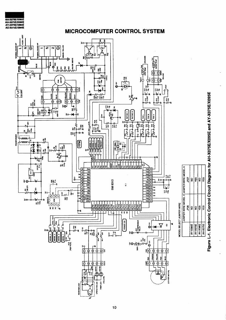
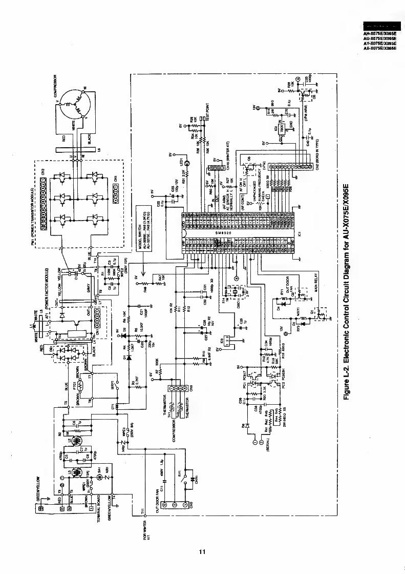
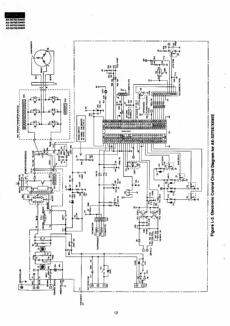
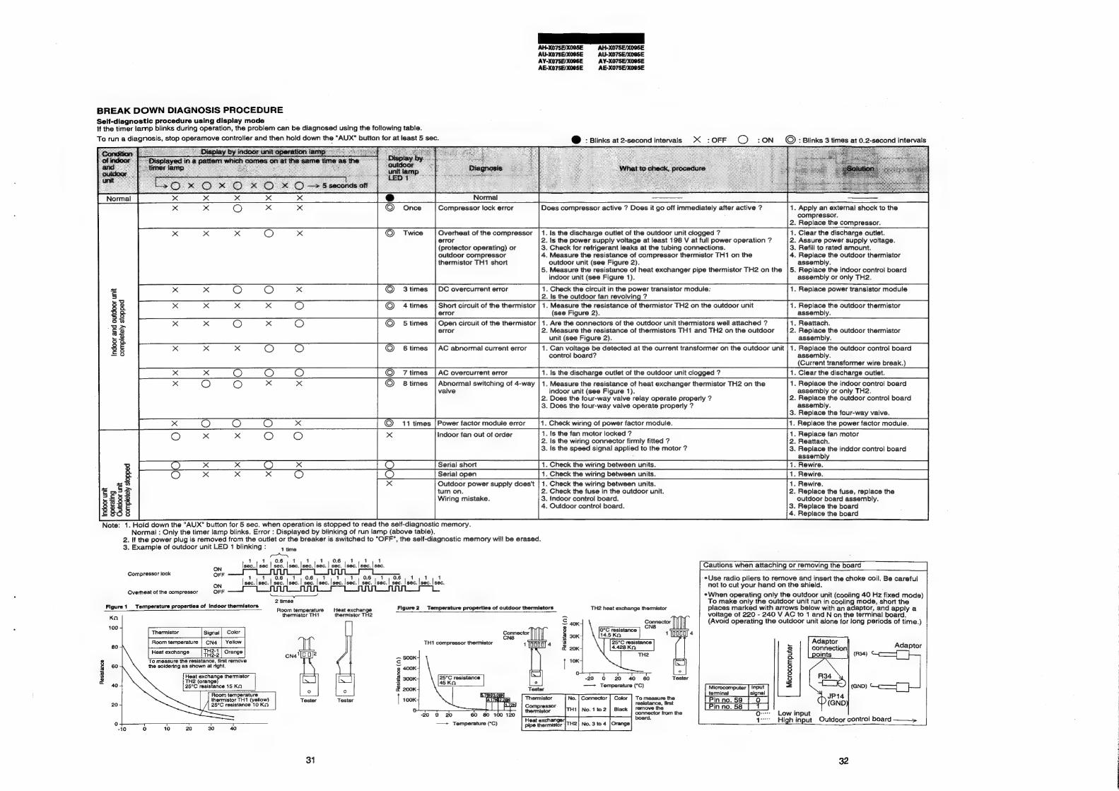
BREAK DOWN DIAGNOSIS PROCEDURE Self-diagnostic procedure using dispiay mode If the timer larnp blinks during operation, the problem can be diagnosed using the following table.
To run a diagnosis, stop operamove controller and then hold down ae "AUX" button for at least 5 sec.
1. Is the discharge outlet of the outdoor unit clogged ? 2. Is the power supply voltage at least 198 V at full power operation ? 3. Check for refrigerant leaks at the tubing connections. 4. Measure the resistance of compressor thermistor TH1 on the
1. Clear the discharge outlet. 2. Assure power supply voltage. 3. Refill to rated amount. 4. Replace the outdoor thermistor
x x x
=
5
s 3S re) 3 a S 3 & completely stopped
x x
completely stopped indoor unit Outdoor unit operating
thermistor TH1 short outdoor unit (see Figure 2). assembly. 5. Measure the resistance of heat exchanger pipe thermistor TH2 on the |5. Replace the indoor control board
indoor unit (see Figure 1). assembly or only TH2.
O PAs <oanee 3times | DC overcurrent error 1. Check the circuit in the Power transistor module: 1. Replace power transistor module 2. Is the outdoor fan revolving ?
Beka 4times | Short circuit of the thermistor | 1. Measure the resistance of thermistor TH2 on the outdoor unit 1. Replace the outdoor thermistor error (see Figure 2). assembly.
Outdoor power supply does't | 1. Check the wiring between units. turn on. 2. Check the fuse in the outdoor unit. Wiring mistake. 3. Indoor control board.
4. Outdoor control board.
Note: 1. Hold down the "AUX" button for 5 sec. when operation is stopped to read the self-diagnostic memory. Normal : Only the timer lamp blinks. Error : Displayed by blinking of run lamp (above table).
2. If the power plug is removed from the outlet or the breaker is switched to "OFF", the self-diagnostic memory will be erased. 3. Example of outdoor unit LED 1 blinking : 1
CN time
6 0. Isec..! sec | sec. | sec. |sec. |sec. | sec. | sec. [sec. |sec.
2 times
ON Compressor lock OFF
ON Overheat of the compressor OFF
Figure 1 Temperature properties of indoor thermistors
Ka
100 - Thermistor | Signal | Color
Room temperature | CN4 | Yellow
TH2-1 Heat exchange TH3-4 | Orange
To measure the resistance, first remove the soldering as shown at right.
. 1 1 |sec. | sec. | sec. | sec. | sec. | sec. lsec. | sec. | sec. | sec. | sec. | sec. |sec. |sec.
Figure 2 Temperature properties of outdoor thermistors TH2 heat exchange thennistor
sistance (1) TH1 compressor thermistor a 20K
8 x | 10K:
rat 20 40 60
i—
-20 0
—— Temperature (°C)
Tester
8 aA
— Resistance (1)
yo + Qa 8 3 A RK
Themnistor To measure the 100K No. | Connector | Color :
ressor resistance, first
2 praelaiehrers TH1| No. 1 to2 | Black | remove the
-20 0 20 60 80 100 120 oe from the
—— Temperature (°C) Heat exchanger|
1. Rewire. 2. Replace the fuse, replace the
outdoor board assembly. 3. Replace the board 4. Replace the board
Cautions when attaching or removing the board
¢Use radio pliers to remove and insert the choke coil. Be careful not to cut your hand on the shield.
When operating only the outdoor unit (cooling 40 Hz fixed mode) To make only the outdoor unit run in cooling mode, short the places marked with arrows below with an adaptor, ‘and apply a voltage of 220 - 240 V AC to 1 and N on the terminal board. (Avoid operating the outdoor unit alone for long periods of time.)
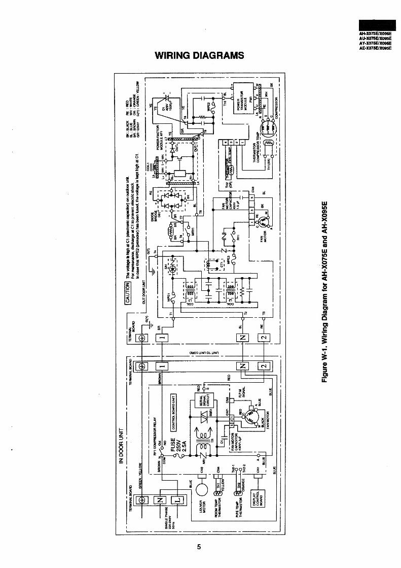
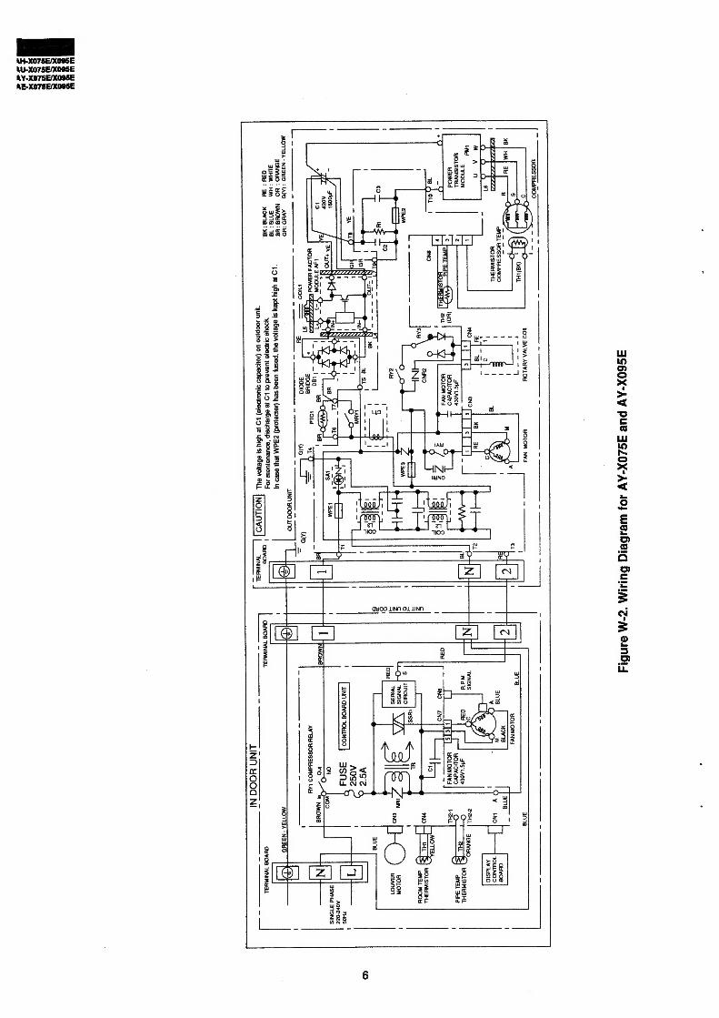
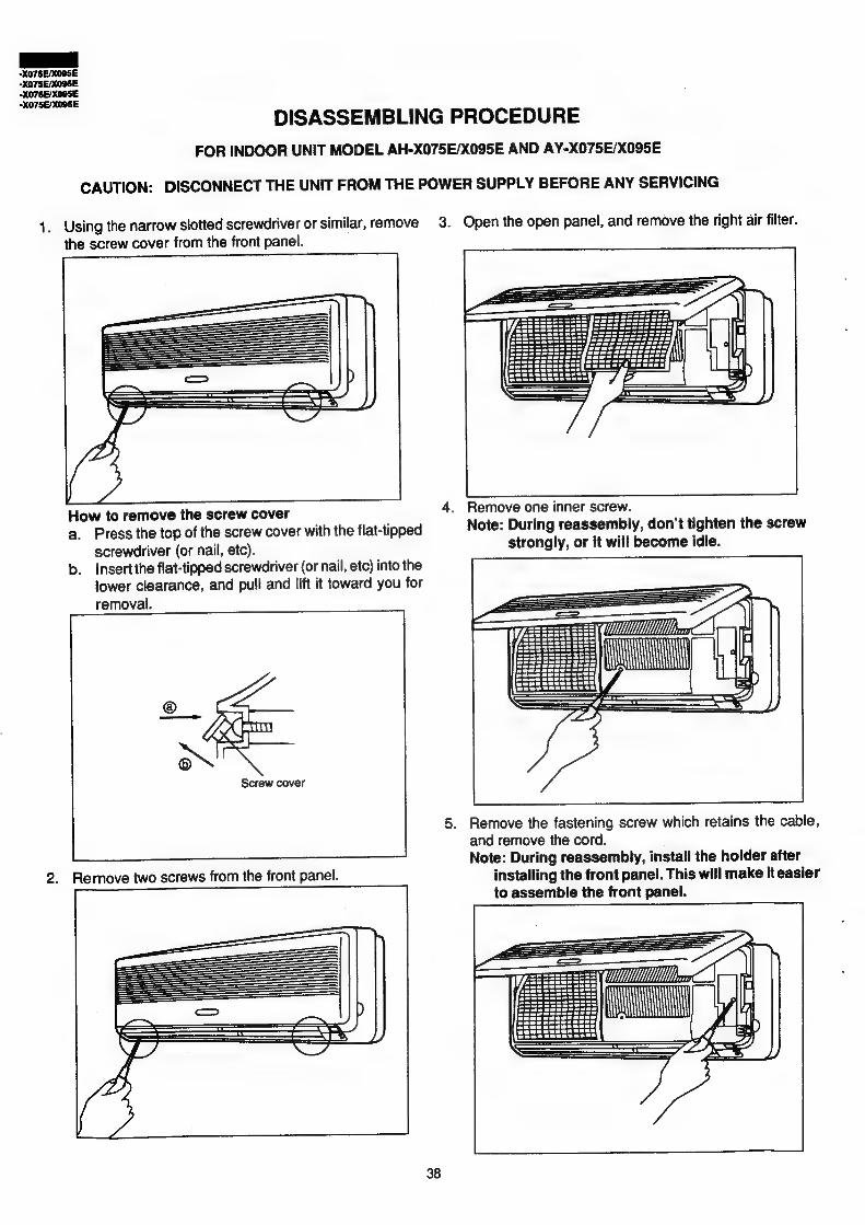
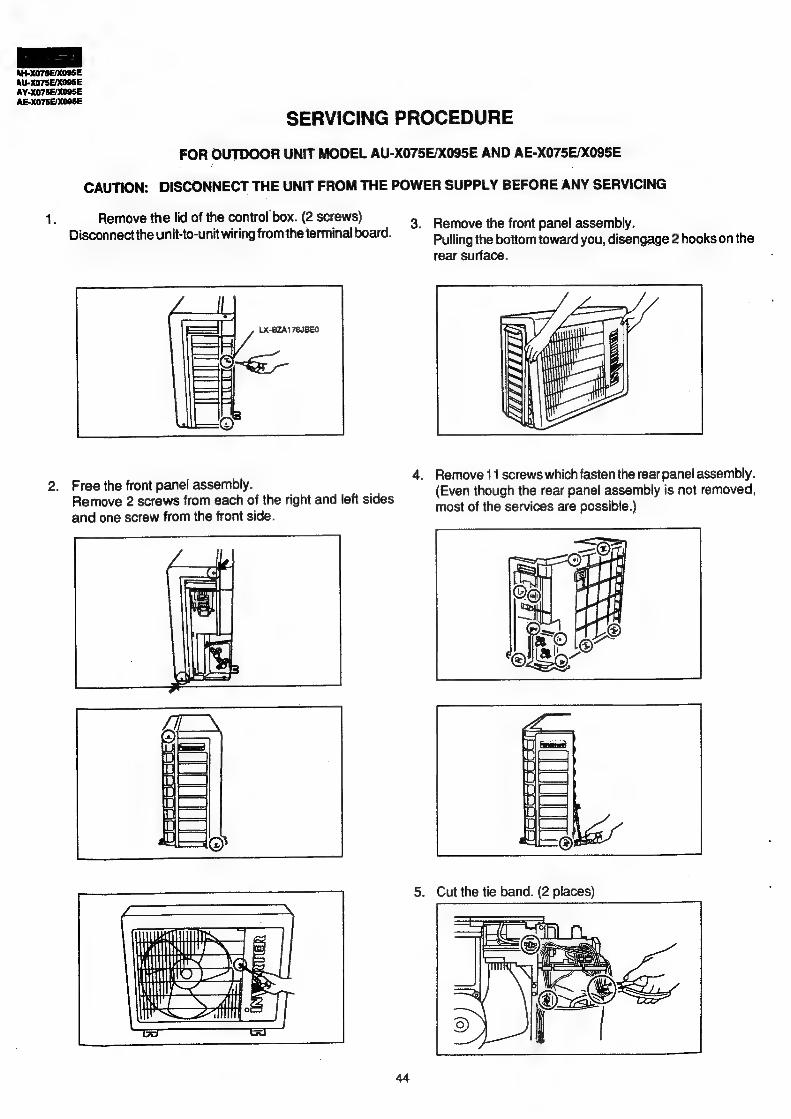
FOR INDOOR UNIT MODEL AH-X075E/X095E AND AY-X075E/X095E
CAUTION: DISCONNECT THE UNIT FROM THE POWER SUPPLY BEFORE ANY SERVICING
1. Using the narrow slotted screwdriver or similar, remove 3. Open the open panel, and remove the right air filter.
the screw cover from the front panel.
How to remove the screw cover 4. Remove one inner screw. a
a. Press the top of the screw cover with the flat-tipped Note: During reassembly, don’t tighten the screw
screwdriver (or nail, etc). strongly, or it will become idle.
b. Insertthe flat-tipped screwdriver (or nail, etc) into the
lower clearance, and pull and lift it toward you for
removal.
o™ Screw cover
5. Remove the fastening screw which retains the cable,
and remove the cord. Note: During reassembly, install the holder after
2. Remove two screws from the front panel. installing the front panel. This will make it easier to assemble the front panel.
mi ih 2 ay i}
Sood
6. After closing the open panel, open the vertical adjustment louver and pull out the bottom of the front panel toward
you. Lifting the front panel, strongly pull the top toward you. Making the front panel parallel to the main body, strongly pull it toward you for removal. To install the front panel, place the bottom of the front panel under the open vertical adjustment louver, and press in the front panel, parallel to the cabinet. When pressing it in, take care to prevent the top of the blow-out port ofthe drain pan from being caught by the front panel.
7. Remove the unit-to-unit wiring from the terminal board. (Loosen the screw with the screwdriver, and pull out the wiring.)
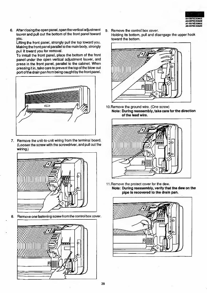
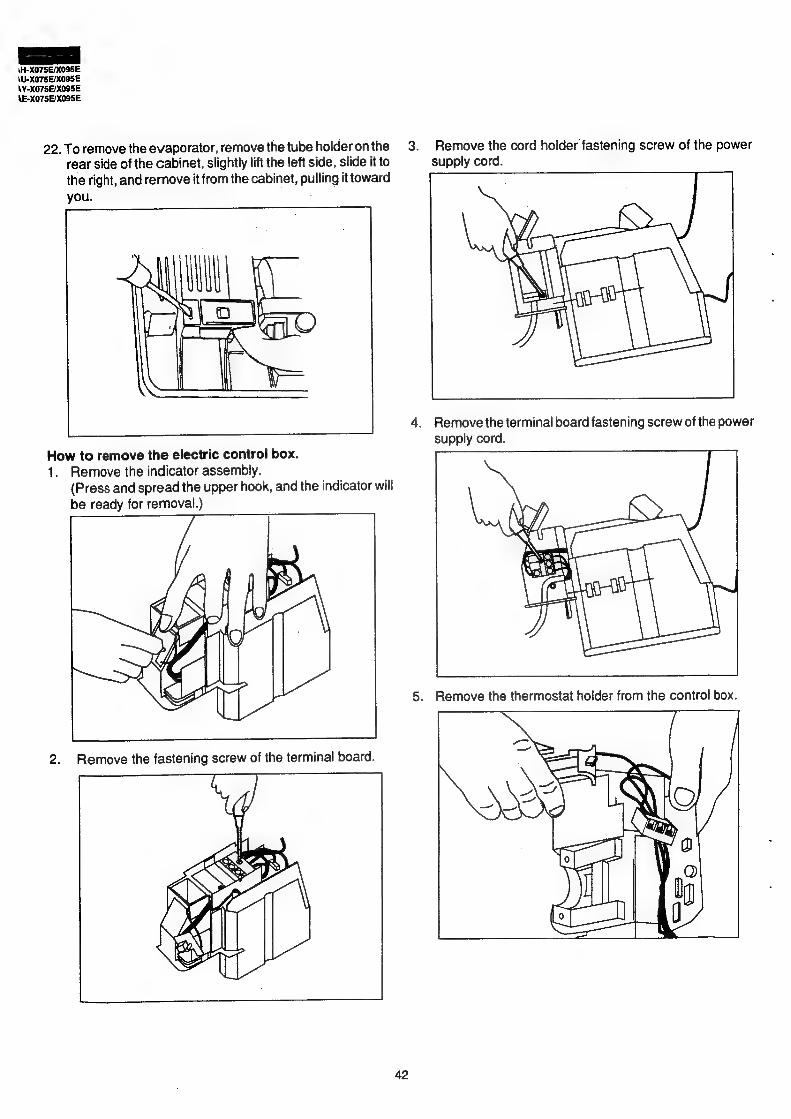
9. Remove the control box cover. Holding its bottom, pull and disengage the upper hook toward the bottom.
Ae 10.Remove the ground wire. (One screw)
Note: During reassembly, take care for the direction of the lead wire.
Pay
M4 |
=U oar ae
SS
11.Remove the protect cover for the dew. Note: During reassembly, verify that the dew on the
pipe is recovered to the drain pan.
yy
i
—,
tt
U-X075E/X09S5E SE/X09SE
E-X075E/X005E
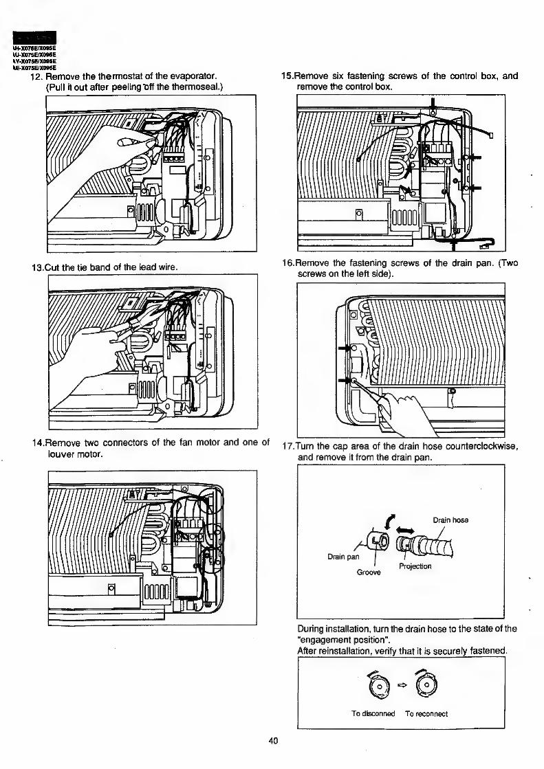
12. Remove the thermostat of the evaporator. 15.Remove six fastening screws of the control box, and
(Pull it out after peeling off the thermoseal.) remove the control box.
MN =a
ie Ee a Ee "t
miei mes <a
16.Remove the arn oe nee screws of the drain pan. (Two screws on the left side).
ee ETD
14.Remove two connectors of the fan motor and one Of 47 Turn the cap area of the drain hose counterclockwise, louver motor. and remove it from the drain pan
AN =a: vi
Tarai — 6 Se tt
Y E ft a! ——+ hon
i)
During installation, turn the drain hose to the state of the
“engagement position”. After reinstallation, verify that it is securely fastened.
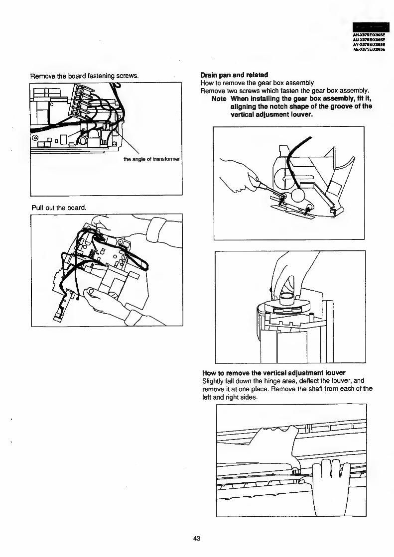
Remove the board fastening screws. Drain pan and related How to remove the gear box assembly Remove two screws which fasten the gear box assembly.
Note When installing the gear box assembly, fit it, aligning the notch shape of the groove of the vertical adjusment louver.
the angle of transformer
Pull out the board.
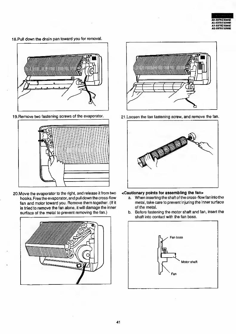
How to remove the vertical adjustment louver Slightly fall down the hinge area, deflect the louver, and remove it at one place. Remove the shaft from each of the left and right sides.
6. Disconnect the connector. (4 places) 9. Remove 2 screws which fasten the motor angle.
Disconnect the Faston terminal. (10 places) Pull up the motor angle for removal. (During reassembling, treat the lead wire to prevent it from being in contact with the propeller fan.)
10. Remove 3 motor fastening screws, and remove the motor.
Remove the 2 screws of the control PWB, and the control circuit will be ready for removal from the control box.
7. Remove 2 fastening screws of the control box. 11. Remove the bulk head.
Remove 2 small screws which fasten the ground cable. Remove 2 fastening screws. Lifting the bulk head, remove
Remove the electric battery box. 2 inner hooks.
Lf}
D jj i i i i i p 0
5
8. 12. Remove 2 screws which fasten the choke coil, and remove the choke coil.
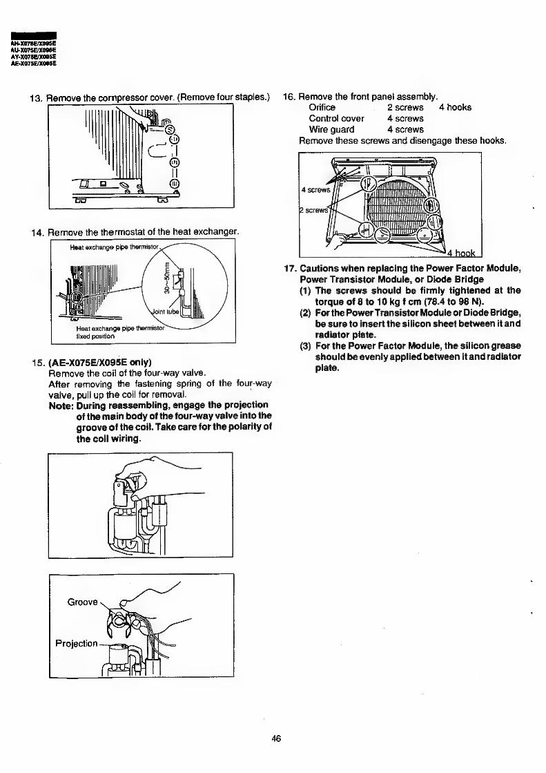
13. Remove the compressor cover. (Remove four staples.) 16. Remove the front panel assembly. Orifice 2screws 4 hooks
| Control cover 4 screws Wire guard 4 screws
Remove these screws and disengage these hooks.
17. Cautions when replacing the Power Factor Module, Power Transistor Module, or Diode Bridge (1) The screws should be firmly tightened at the
torque of 8 to 10 kg f cm (78.4 to 98 N). (2) For the Power Transistor Module or Diode Bridge,
Heat exchange pipe thermistor be sure to insert the silicon sheet between it and fixed position radiator plate.
(3) For the Power Factor Module, the silicon grease
should be evenly applied between it and radiator plate.
15. (AE-X075E/X095E only) Remove the coil of the four-way valve. After removing the fastening spring of the four-way valve, pull up the coil for removal. . Note: During reassembling, engage the projection
of the main body of the four-way valve into the groove of the coil. Take care for the polarity of the coil wiring.
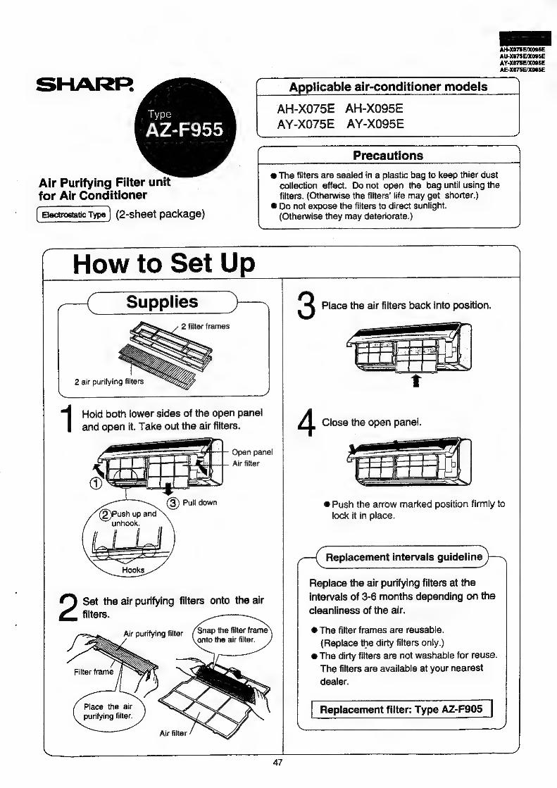
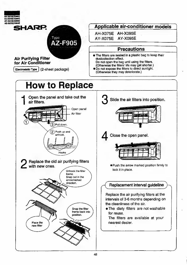
@ The filters are sealed in a plastic bag to keep thier dust collection effect. Do not open the bag until using the filters. (Otherwise the filters’ life may get shorter.)
®@ Do not expose the filters to direct sunlight. (Otherwise they may deteriorate.)
Type
AW Aa mac loye)
Air Purifying Filter unit for Air Conditioner
(2-sheet package)
How to Set Up
3 Place the air filters back into position.
cee /
aan oe —eew ij
At
1 Hold both lower sides of the open panel
and open it. Take out the air filters. 4 Close the open panel.
ro | x. Air filter SHAS @) Pull down @ Push the arrow marked position firmly to
Push up and lock it in place. unhook.
LoLbed Replacement intervals guideline
Hooks
Replace the air purifying filters at the
intervals of 3-6 months depending on the Set the air purifying filters onto the air cleanliness of the air. filters.
@ The filters are sealed in a plastic bag to keep their dustcollection effect. Do not open the bag until using the filters. (Otherwise the filters’ life may get shorter.)
@ Do not expose the filters to direct sunlight. (Otherwise they may deteriorate.)
How to Replace Open the panel and take out the air filters.
Open panel! a peat Tat | ic titer * aching’ _—_—}— Jats E83 Seer
an ae. Uy ara ——— —_
Replace the old air purifying filters with new ones.