Page 1
AHBMH DEE2113 : Chapter 5 - Transformer & Mutual Inductance
1
CHAPTER 5: TRANSFORMER CHAPTER 5: TRANSFORMER AND MUTUAL INDUCTANCEAND MUTUAL INDUCTANCE
• Review of Magnetic Induction• Mutual Inductance• Linear & Ideal Transformers
Page 2
Magnetic Field Lines
Magnetic fields can be visualized as lines of flux that form closed paths
The flux density vector B is tangent to the lines of flux
density flux MagneticB
Page 3
Magnetic Fields
• Magnetic flux lines form closed paths that are close together where the field is strong and farther apart where the field is weak.
• Flux lines leave the north-seeking end of a magnet and enter the south-seeking end.
• When placed in a magnetic field, a compass indicates north in the direction of the flux lines.
Page 5
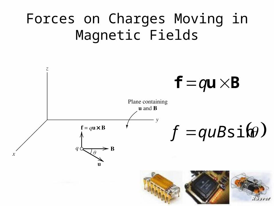
Buf q
sinquBf
Forces on Charges Moving in Magnetic Fields
Page 6
Bl
Bl
Bl
f
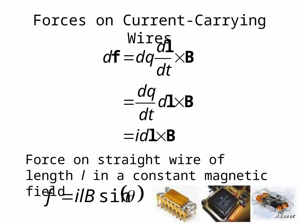
id
ddt
dqdt
ddqd
sinilBf
Force on straight wire of length l in a constant magnetic field
Forces on Current-Carrying Wires
Page 7
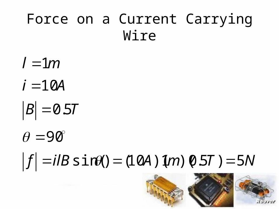
Force on a Current Carrying Wire
NTmAilBf
TB
Ai
ml
5)5.0)(1)(10()sin(
90
5.0
10
1
Page 8
Flux Linkages and Faraday’s Law
N
BA
dA
AB
Magnetic flux passing through a surface area A:
For a constant magnetic flux density perpendicular to the surface:
The flux linking a coil with N turns:
Page 9
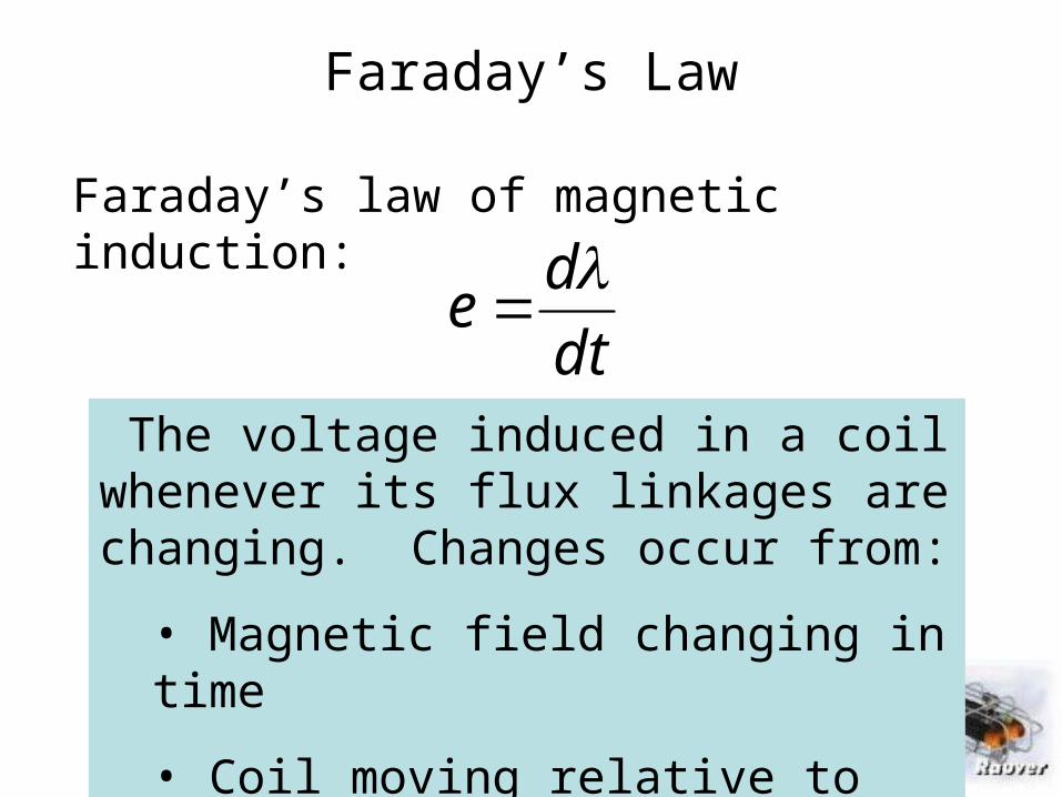
Faraday’s Law
Faraday’s law of magnetic induction:
dt
de
The voltage induced in a coil whenever its flux linkages are changing. Changes occur from:
• Magnetic field changing in time
• Coil moving relative to magnetic field
Page 10
Lenz’s law states that the polarity of the induced voltage is such that the voltagewould produce a current (through an external resistance) that opposes the original change in flux linkages.
Lenz’s Law
Page 12
AHBMH DEE2113 : Chapter 5 - Transformer & Mutual Inductance
12
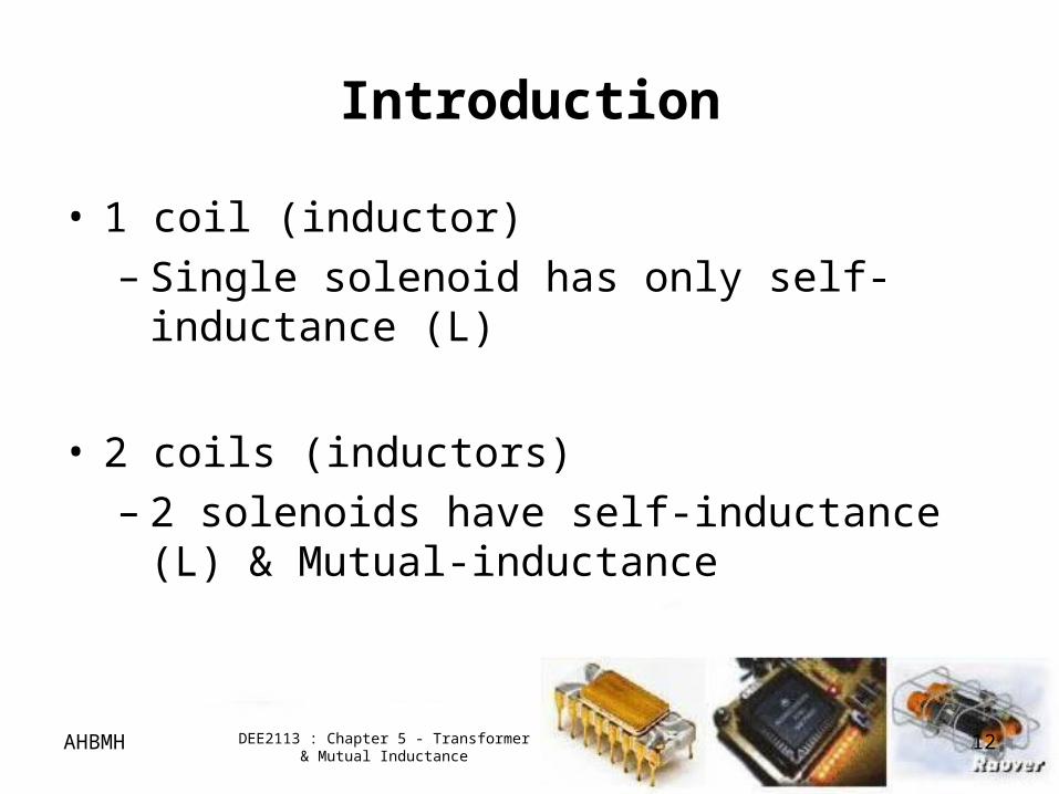
Introduction
• 1 coil (inductor)– Single solenoid has only self-inductance (L)
• 2 coils (inductors)– 2 solenoids have self-inductance (L) & Mutual-
inductance
Page 13
AHBMH DEE2113 : Chapter 5 - Transformer & Mutual Inductance
13
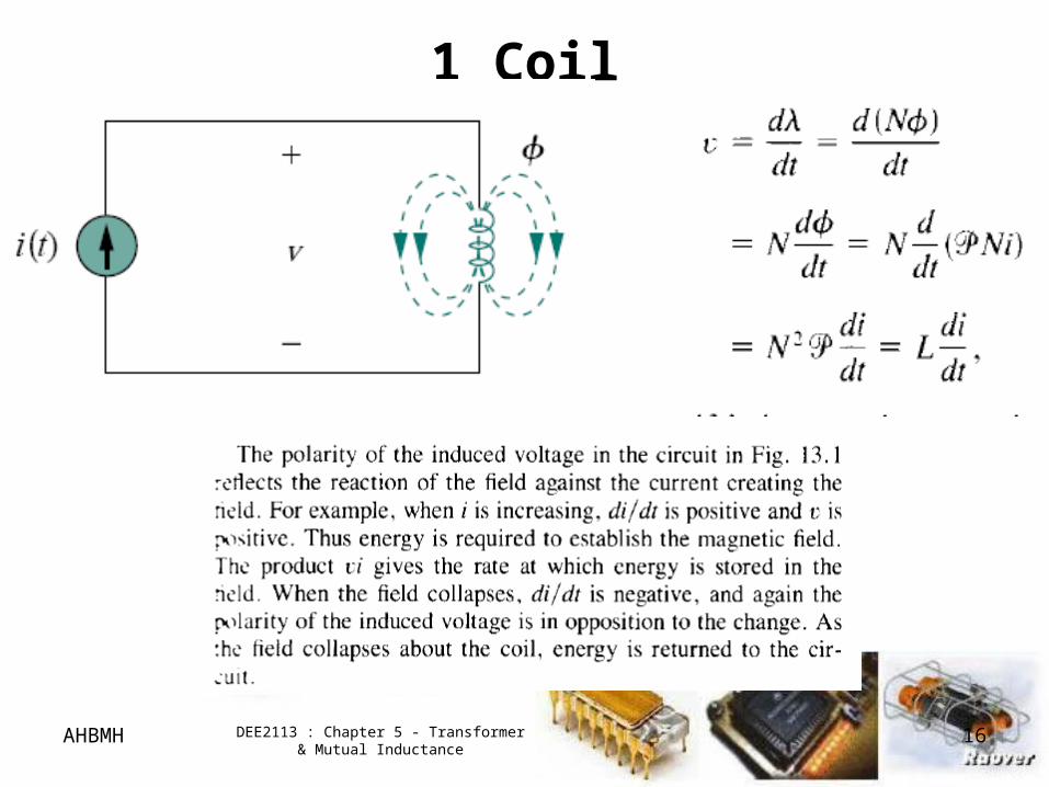
1 Coil
• A coil with N turns produced = magnetic flux
• only has self inductance, L
Page 14
AHBMH DEE2113 : Chapter 5 - Transformer & Mutual Inductance
14
1 Coil
Page 15
AHBMH DEE2113 : Chapter 5 - Transformer & Mutual Inductance
15
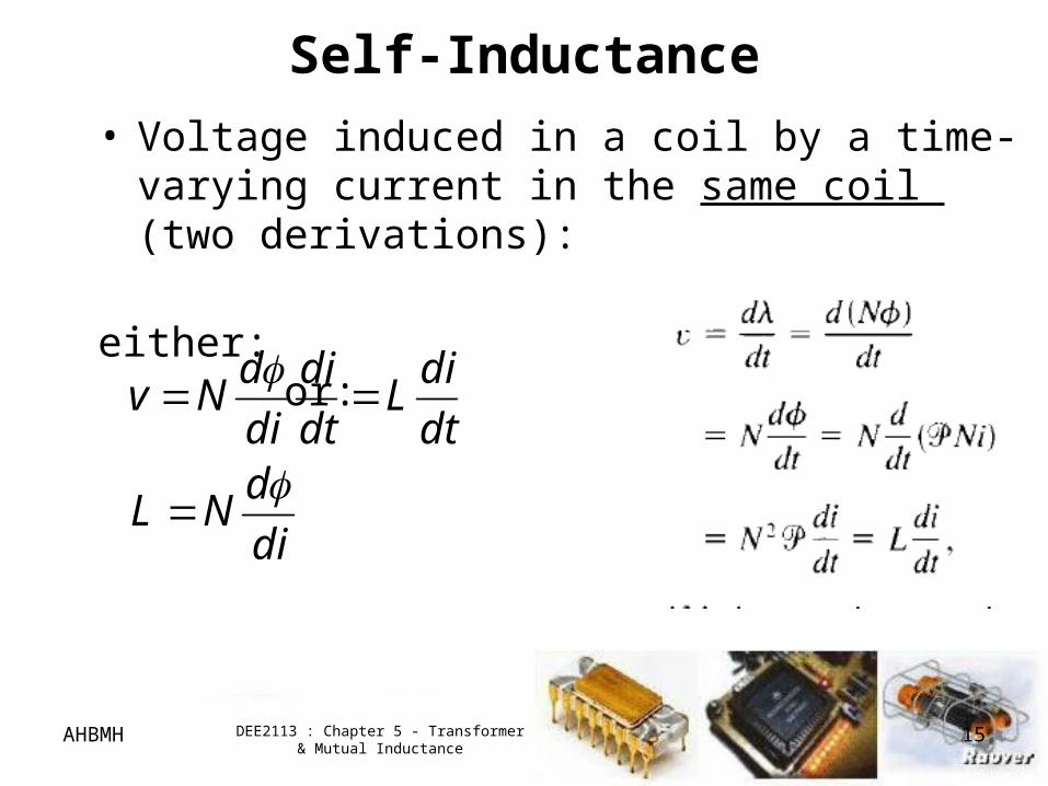
Self-Inductance
• Voltage induced in a coil by a time-varying current in the same coil (two derivations):
either: or:
di
dNL
dt
diL
dt
di
di
dNv
Page 16
AHBMH DEE2113 : Chapter 5 - Transformer & Mutual Inductance
16
1 Coil
Page 17
AHBMH DEE2113 : Chapter 5 - Transformer & Mutual Inductance
17
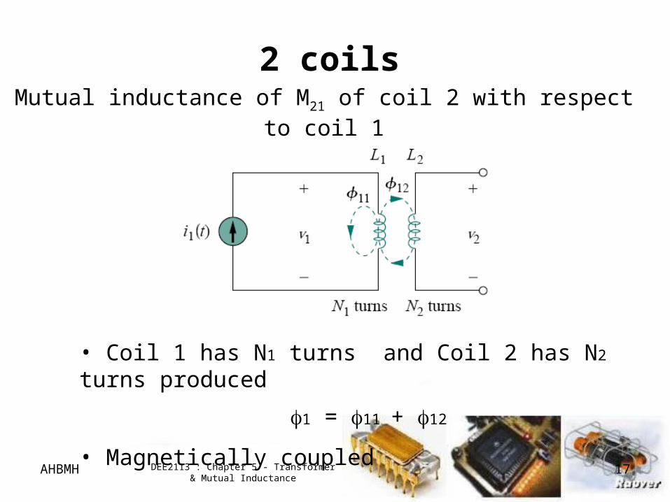
2 coils
Mutual inductance of M21 of coil 2 with respect to coil 1
• Coil 1 has N1 turns and Coil 2 has N2 turns produced
1 = 11 + 12
• Magnetically coupled
Page 18
AHBMH DEE2113 : Chapter 5 - Transformer & Mutual Inductance
18
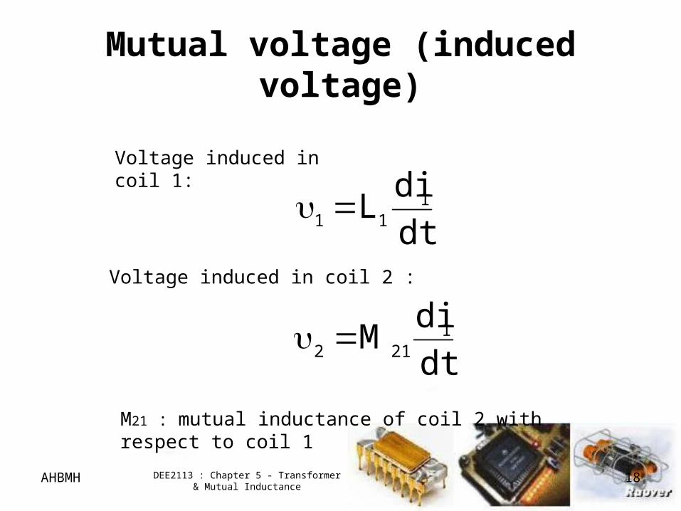
Mutual voltage (induced voltage)
Voltage induced in coil 1:
dt
diL 1
11
Voltage induced in coil 2 :
dt
diM 1
212
M21 : mutual inductance of coil 2 with respect to coil 1
Page 19
AHBMH DEE2113 : Chapter 5 - Transformer & Mutual Inductance
19
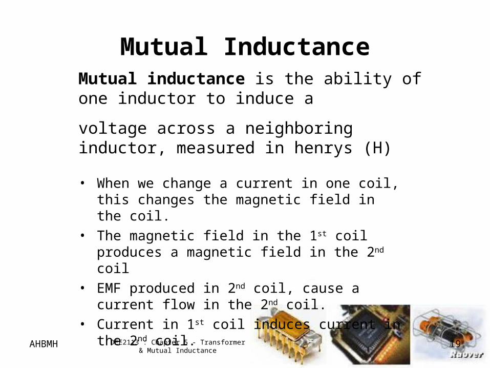
Mutual Inductance
• When we change a current in one coil, this changes the magnetic field in the coil.
• The magnetic field in the 1st coil produces a magnetic field in the 2nd coil
• EMF produced in 2nd coil, cause a current flow in the 2nd coil.
• Current in 1st coil induces current in the 2nd coil.
Mutual inductance is the ability of one inductor to induce a
voltage across a neighboring inductor, measured in henrys (H)
Page 20
AHBMH DEE2113 : Chapter 5 - Transformer & Mutual Inductance
20
2 coils
Mutual inductance of M12 of coil 1 with respect to coil 2
• Coil 1 has N1 turns and Coil 2 has N2 turns produced
2 = 21 + 22
• Magnetically coupled
Page 21
AHBMH DEE2113 : Chapter 5 - Transformer & Mutual Inductance
21
Mutual voltage (induced voltage)
Voltage induced in coil 2:
dt
diL 2
22
Voltage induced in coil 1 :
dt
diM 2
121
M12 : mutual inductance of coil 1 with respect to coil 2
Page 22
AHBMH DEE2113 : Chapter 5 - Transformer & Mutual Inductance
22
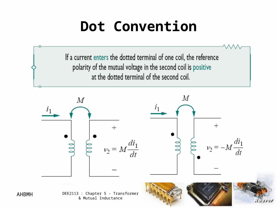
Dot Convention
• Not easy to determine the polarity of mutual voltage –
4 terminals involved
• Apply dot convention
Page 23
AHBMH DEE2113 : Chapter 5 - Transformer & Mutual Inductance
23
Dot Convention
Page 24
AHBMH DEE2113 : Chapter 5 - Transformer & Mutual Inductance
24
Dot Convention
Page 25
AHBMH DEE2113 : Chapter 5 - Transformer & Mutual Inductance
25
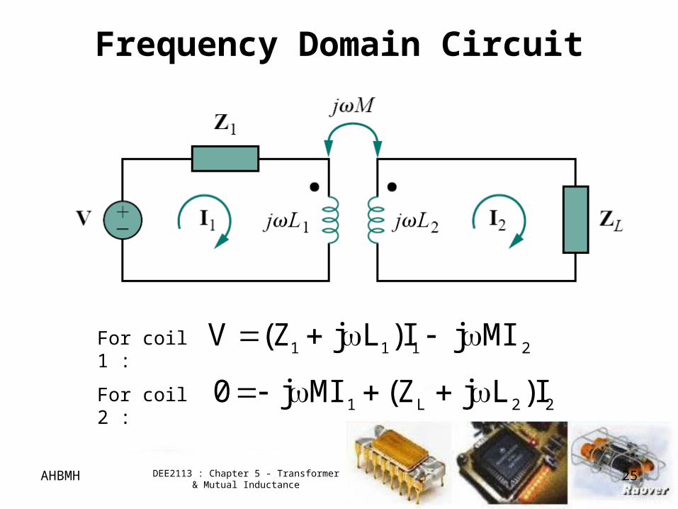
Frequency Domain Circuit
2111 MIjI)LjZ(V
22L1 I)LjZ(MIj0
For coil 1 :
For coil 2 :
Page 26
AHBMH DEE2113 : Chapter 5 - Transformer & Mutual Inductance
26
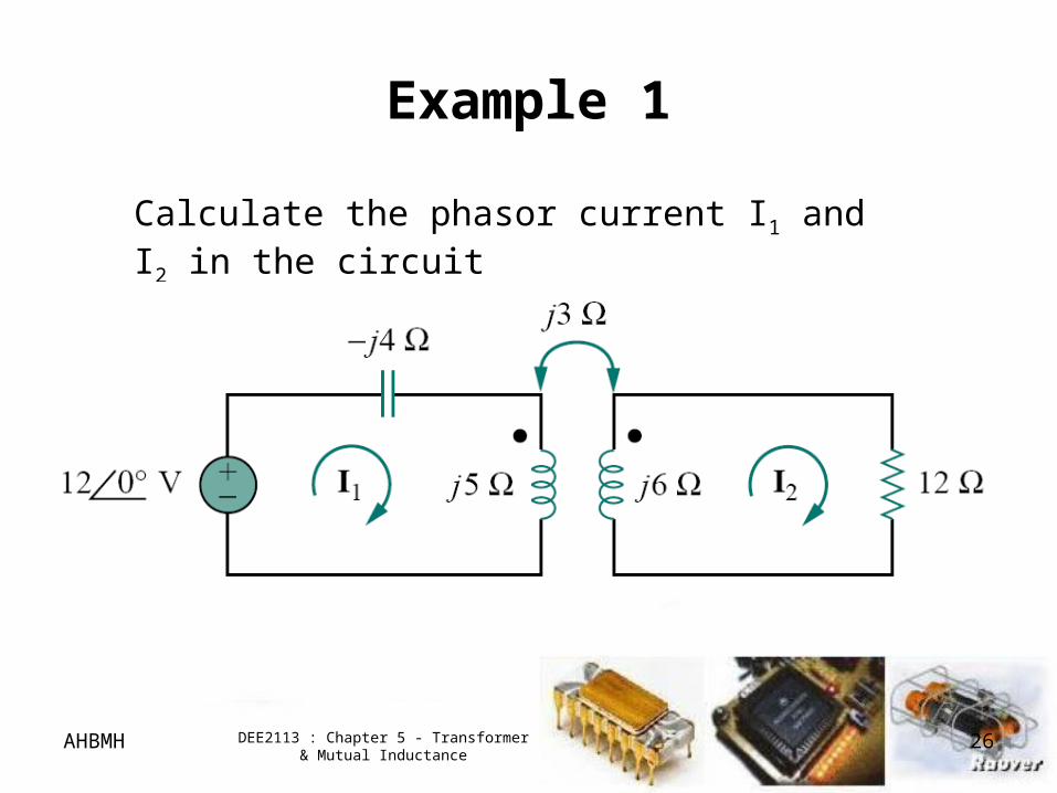
Example 1
Calculate the phasor current I1 and I2 in the circuit
Page 27
AHBMH DEE2113 : Chapter 5 - Transformer & Mutual Inductance
27
Exercise 1
Determine the voltage Vo in the circuit
Page 28
AHBMH DEE2113 : Chapter 5 - Transformer & Mutual Inductance
28
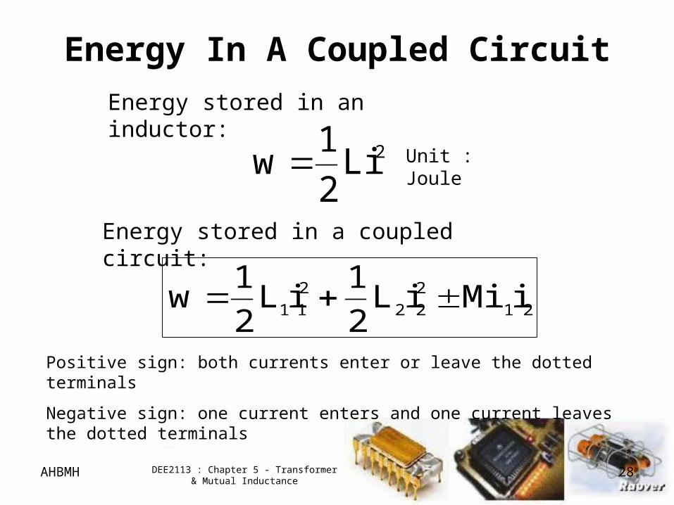
Energy In A Coupled Circuit
2Li2
1w
Energy stored in an inductor:
21
2
22
2
11 iMiiL2
1iL
2
1w
Energy stored in a coupled circuit:
Positive sign: both currents enter or leave the dotted terminals
Negative sign: one current enters and one current leaves the dotted terminals
Unit : Joule
Page 29
AHBMH DEE2113 : Chapter 5 - Transformer & Mutual Inductance
29
1L
. .
M
2L
+ +
--
1v 2v
1i 2i
Coupled Circuit
Energy In A Coupled Circuit
Page 30
AHBMH DEE2113 : Chapter 5 - Transformer & Mutual Inductance
30
0iMiiL2
1iL
2
121
2
22
2
11
Energy stored must be greater or equal to zero.
0MLL 21 21LLM or
Mutual inductance cannot be greater than the geometric mean of self inductances.
Energy In A Coupled Circuit
Page 31
AHBMH DEE2113 : Chapter 5 - Transformer & Mutual Inductance
31
The coupling coefficient k is a measure of the magnetic coupling between two coils
21LL
Mk
21LLkM
1k0 21LLM0
or
Where:
or
Energy In A Coupled Circuit
1k0
Page 32
AHBMH DEE2113 : Chapter 5 - Transformer & Mutual Inductance
32
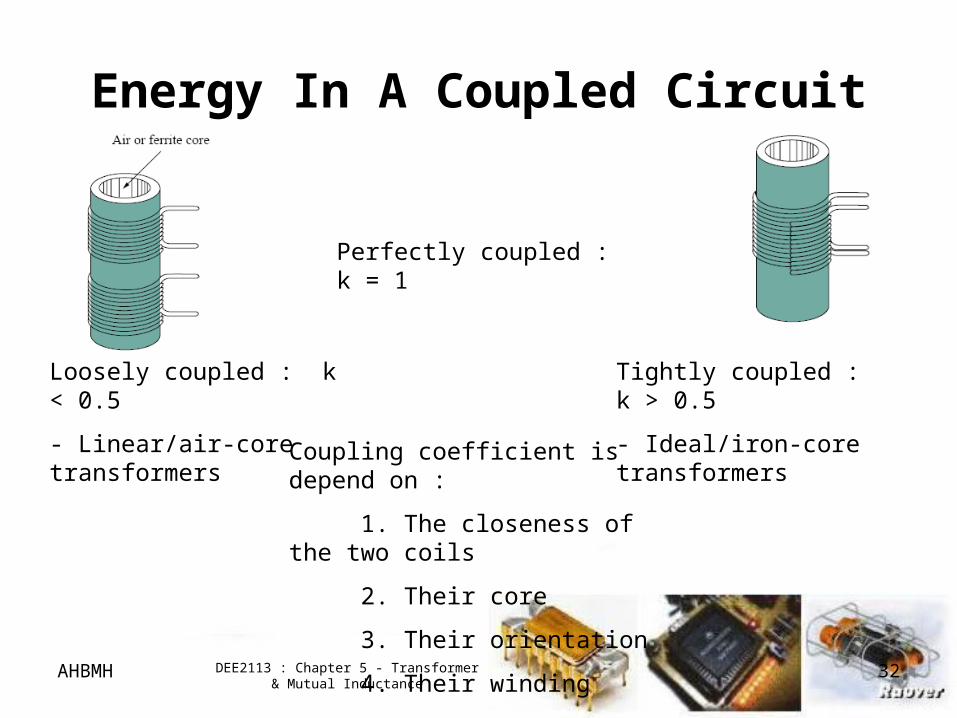
Perfectly coupled : k = 1
Loosely coupled : k < 0.5
- Linear/air-core transformers
Tightly coupled : k > 0.5
- Ideal/iron-core transformers
Coupling coefficient is depend on :
1. The closeness of the two coils
2. Their core
3. Their orientation
4. Their winding
Energy In A Coupled Circuit
Page 33
AHBMH DEE2113 : Chapter 5 - Transformer & Mutual Inductance
33
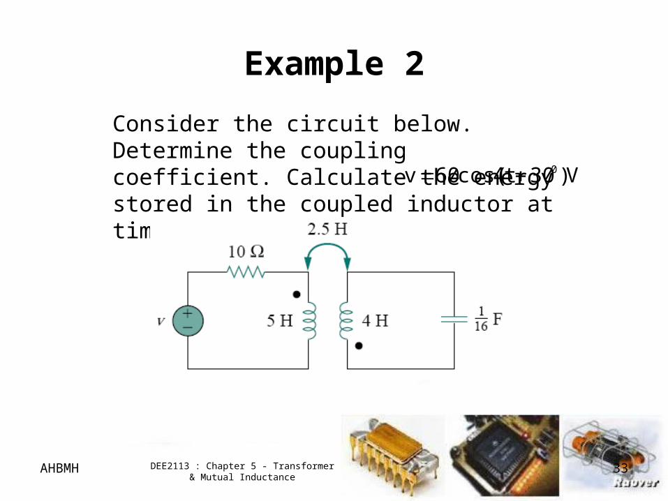
Example 2
Consider the circuit below. Determine the coupling coefficient. Calculate the energy stored in the coupled inductor at time t=1s if V)30t4cos(60v 0
Page 34
AHBMH DEE2113 : Chapter 5 - Transformer & Mutual Inductance
34
Exercise 2
For the circuit below, determine the coupling coefficient and the energy stored in the coupled inductors at t=1.5s.
Page 35
AHBMH DEE2113 : Chapter 5 - Transformer & Mutual Inductance
35
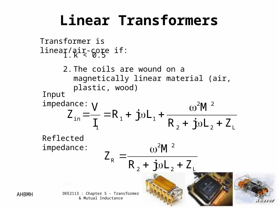
Linear TransformersTransformer is linear/air-core if:
1. k < 0.5
2. The coils are wound on a magnetically linear material (air, plastic, wood)
L22
22
R ZLjR
MZ
Reflected impedance:
L22
22
11
1
in ZLjR
MLjR
I
VZ
Input impedance:
Page 36
AHBMH DEE2113 : Chapter 5 - Transformer & Mutual Inductance
36
Linear Transformers
An equivalent T circuit
MLL 1a MLL 2b MLc
An equivalent circuit of linear transformer
Page 37
AHBMH DEE2113 : Chapter 5 - Transformer & Mutual Inductance
37
Linear Transformers
ML
MLLL
2
2
21A
ML
MLLL
1
2
21B
M
MLLL
2
21C
An equivalent circuit of linear transformer
An equivalent П/ circuit
Page 38
AHBMH DEE2113 : Chapter 5 - Transformer & Mutual Inductance
38
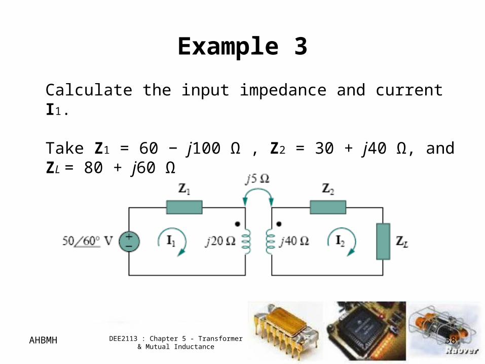
Example 3
Calculate the input impedance and current I1.
Take Z1 = 60 − j100 Ω , Z2 = 30 + j40 Ω, and ZL = 80 + j60 Ω
Page 39
AHBMH DEE2113 : Chapter 5 - Transformer & Mutual Inductance
39
Exercise 3
For the linear transformer below, find the
T-equivalent circuit and П equivalent circuit.
Page 40
AHBMH DEE2113 : Chapter 5 - Transformer & Mutual Inductance
40
Ideal Transformer
1.An ideal transformer has:
• 2/more coils with large numbers of turns wound on an common core of high permeability.
• Flux links all the turn of both coil – perfect coupling
2. Transformer is ideal if it has:
• Coils with large reactances (L1,L2, M → ∞)
• Coupling coefficient is unity (k=1)
• Lossless primary and secondary coils (R1 = R2 = 0)
Page 41
AHBMH DEE2113 : Chapter 5 - Transformer & Mutual Inductance
41
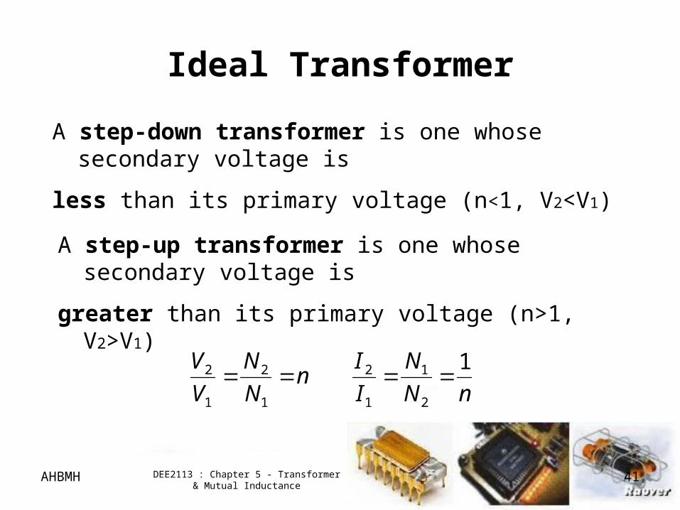
Ideal Transformer
A step-down transformer is one whose secondary voltage is
less than its primary voltage (n<1, V2<V1)
A step-up transformer is one whose secondary voltage is
greater than its primary voltage (n>1, V2>V1)
nN
N
I
In
N
N
V
V 1
2
1
1
2
1
2
1
2
Page 42
AHBMH DEE2113 : Chapter 5 - Transformer & Mutual Inductance
42
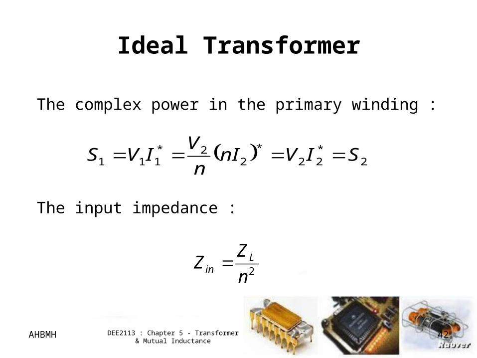
Ideal Transformer
2*22
*2
2*111 SIVnI
n
VIVS
The complex power in the primary winding :
The input impedance :
2n
ZZ L
in
Page 43
AHBMH DEE2113 : Chapter 5 - Transformer & Mutual Inductance
43
Example 4
An ideal transformer is rated at 2400/120 V, 9.6 kVA
and has 50 turns on the secondary side. Calculate :
a) The turns ratio
b) The number of turns on the primary side
c) The currents ratings for the primary and secondary windings
Page 44
AHBMH DEE2113 : Chapter 5 - Transformer & Mutual Inductance
44
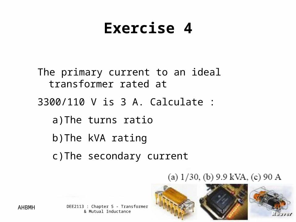
Exercise 4
The primary current to an ideal transformer rated at
3300/110 V is 3 A. Calculate :
a) The turns ratio
b) The kVA rating
c) The secondary current
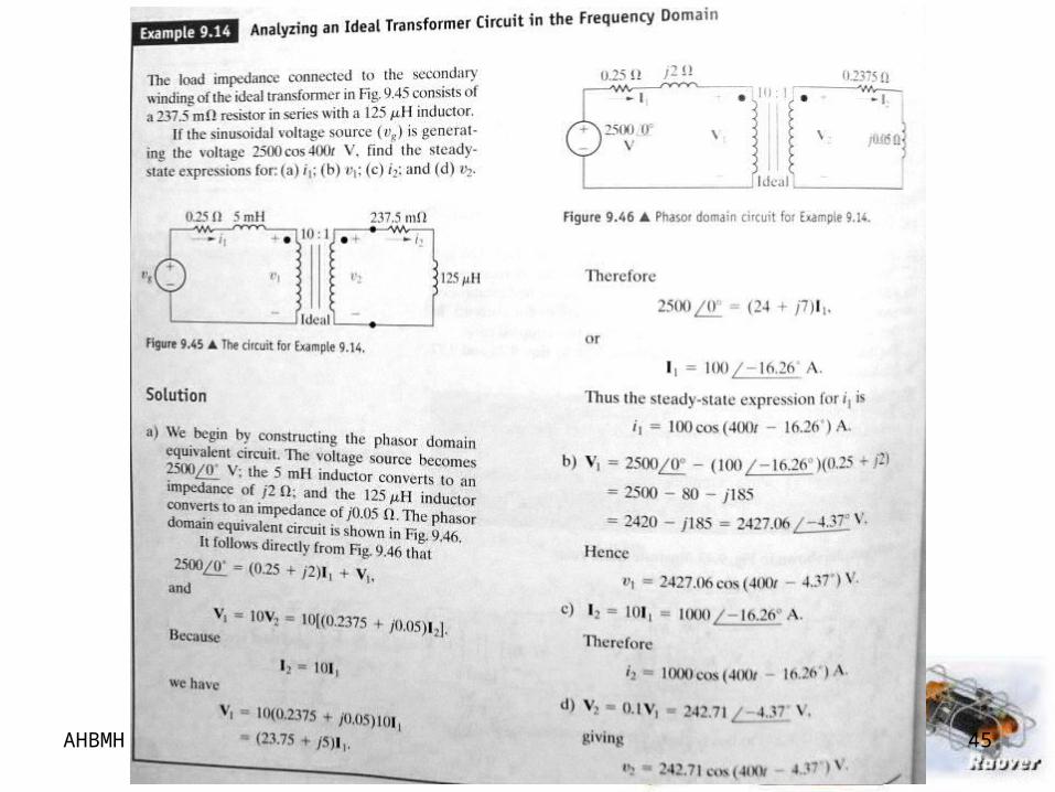
Page 45
AHBMH DEE2113 : Chapter 5 - Transformer & Mutual Inductance
45
Page 46
AHBMH DEE2113 : Chapter 5 - Transformer & Mutual Inductance
46
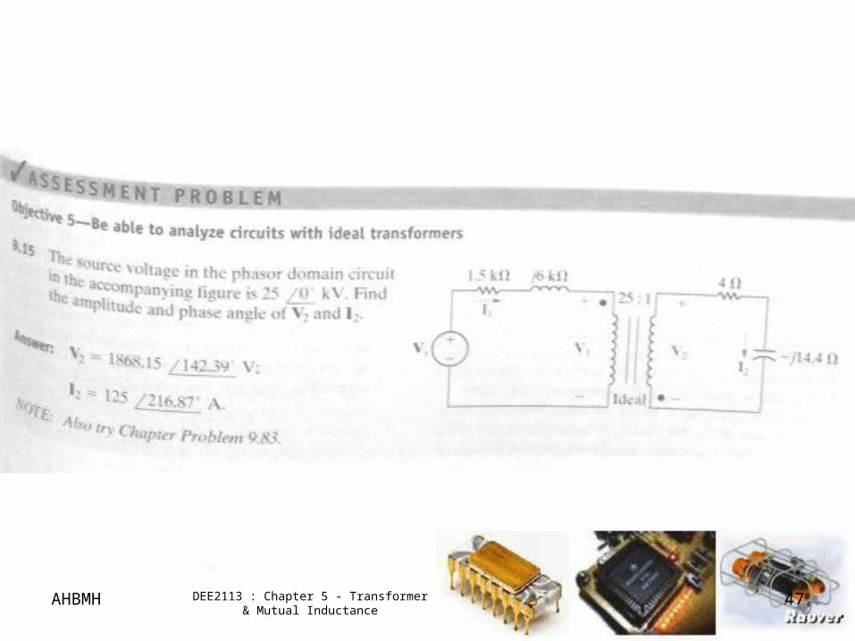
Page 47
AHBMH DEE2113 : Chapter 5 - Transformer & Mutual Inductance
47


![Inductance, Capacitance, and Mutual Inductancefaculty.weber.edu/snaik/ECE1270/Ch6.pdfInductance, Capacitance, and Mutual Inductance Assessment Problems AP 6.1 [a] ig = 8e−300t −](https://static.documents.pub/doc/80x56/5f0246127e708231d4037222/inductance-capacitance-and-mutual-inductance-capacitance-and-mutual-inductance.jpg)


