- Source of Acquisition NASA Johnson Space Center AIAA 2001-5039 A STREAMLINED APPROACH FOR THE PAYLOAD CUSTOMER IN IDENTIFYING PAYLOAD DESIGN REQUIREMENTS Ladonna J. Miller NASAJSC Houston, Texas USA Walter F. Schneider NASA MSFC Huntsville, Alabama USA Dexer E. Johnson NASAJSC Houston , Texas USA Lesa B. Roe NASAJSC Houston , Texas USA ABSTRACT NASA payload developers from across various disciplines were asked to identify areas where process changes would simplify their task of developing and flying flight hardware. Responses to this query included a central location for consistent hardware design requirements for middeck payloads. The multidisciplinary team assigned to review the numerous payload interface design documents is assessing the Space Shuttle middeck, the SPACEHAB Inc. locker, as well as the Multi- Purpose Logistics Module (MPLM) and EXpedite the PRocessing of Experiments to Space Station (EXPRESS) rack design requirements for the payloads. They are comparing the multiple carriers and platform requirements and developing a matrix which illustrates the individual requ irements , and where possible, the envelope that encompasses all of the possibilities. The matrix will be expanded to form an overall envelope that the payload developers will have the option to utilize when designing their payload's hardware. This will optimize the flexibility for payload hardware and ancillary items to be manifested on multiple carriers and platforms with minimal impact to the payload developer. Th is paper is declared a work of th e U.S. Government and is not subject to copyright protection in the United States. Background Every human-rated vehicle and platform used in the extreme environment of space is incredibly complex. They have been developed to meet specific goals such as exploration , research , and construction. Each vehicle is deSigned to optimize the technology available at that time. Therefore, the overall characteristics of the Space Shuttle, a twenty year old design with the overall goal of being a reusable vehicle, as compared to the newer design of the International Space Station (ISS), which has the overall goal of being a continuously orbiting platform, are remarkably different. These differences are throughout the entire vehicles including the crew compartment and module interiors, and even to the rack level. With this diversity, the envelope of acceptable physical and environmental interfaces are markedly varied. These variances are due to the interface constraints and limitations inherent to both the Shuttle and the ISS. The structural, thermal, EMI /EMC and acoustical characteristics for crew compartment of the Space Shuttle differ from those of the interior of the Space Station. These types of differences cause the complexity of hardware to significantly increase if the hardware must be verified for more than one environment. American Institute of Aeronautics and Astronautics ---------- - https://ntrs.nasa.gov/search.jsp?R=20100033412 2018-07-08T20:26:10+00:00Z
Transcript
f----~ -Source of Acquisition
NASA Johnson Space Center
AIAA 2001-5039
A STREAMLINED APPROACH FOR THE PAYLOAD CUSTOMER IN IDENTIFYING PAYLOAD DESIGN REQUIREMENTS
Ladonna J. Miller NASAJSC Houston , Texas USA
Walter F. Schneider NASA MSFC Huntsville, Alabama USA
Dexer E. Johnson NASAJSC Houston , Texas USA
Lesa B. Roe NASAJSC Houston , Texas USA
ABSTRACT
NASA payload developers from across various disciplines were asked to identify areas where process changes would simplify their task of developing and flying flight hardware. Responses to this query included a central location for consistent hardware design requirements for middeck payloads. The multidisciplinary team assigned to review the numerous payload interface design documents is assessing the Space Shuttle middeck, the SPACEHAB Inc. locker, as well as the MultiPurpose Logistics Module (MPLM) and EXpedite the PRocessing of Experiments to Space Station (EXPRESS) rack design requirements for the payloads. They are comparing the multiple carriers and platform requirements and developing a matrix which illustrates the individual requ irements , and where possible, the envelope that encompasses all of the possibilities. The matrix will be expanded to form an overall envelope that the payload developers will have the option to utilize when designing their payload's hardware. This will optimize the flexibility for payload hardware and ancillary items to be manifested on multiple carriers and platforms with minimal impact to the payload developer.
Th is paper is declared a work of the U.S. Government and is not subject to copyright protection in the United States.
Background
Every human-rated vehicle and platform used in the extreme environment of space is incredibly complex. They have been developed to meet specific goals such as exploration, research , and construction . Each vehicle is deSigned to optimize the technology available at that time. Therefore, the overall characteristics of the Space Shuttle , a twenty year old design with the overall goal of being a reusable vehicle , as compared to the newer design of the International Space Station (ISS) , which has the overall goal of being a continuously orbiting platform, are remarkably different. These differences are throughout the entire vehicles including the crew compartment and module interiors, and even to the rack level. With this diversity, the envelope of acceptable physical and environmental interfaces are markedly varied. These variances are due to the interface constraints and limitations inherent to both the Shuttle and the ISS. The structural, thermal, EMI/EMC and acoustical characteristics for crew compartment of the Space Shuttle differ from those of the interior of the Space Station . These types of differences cause the complexity of hardware to significantly increase if the hardware must be verified for more than one environment.
American Institute of Aeronautics and Astronautics
The Space Shuttle Program overall payload design requirements are documented in the Shuttle Orbiter/Cargo Standard Interface Control Document - ICD 2-19001 . These requirements include pass/fail specifications such as environmental measures, e.g. electromagnetic interference and conductance, factors of safety and utilization for structural assessments, power constraints, and numerous other areas. The subset of requirements applicable to the habitable area of the Space Shuttle vehicles are documented in the Middeck Interface Definition Document - NSTS 21 OOO-MDK-IDD. This is commonly referred to as the middeck 100. The middeck 100 requirements were incorporated into the EXPRESS Rack requirements documen EXPRESS Rack Payloads 100, SSP 52000-EXP-IDD. The EXPRESS 100 defines the requirements a payload developer must meet to be transported to the ISS and perform science in the EXPRESS Rack.
Status
A team of Space Shuttle Program (SSP) and ISS Program (ISSP) personnel were tasked to review the processes that a payload customer experiences when they fly a payload on both the Shuttle and the ISS. The major objective of the team was to simplify the customer interface to the ISS and the Shuttle Programs. A specific
Common Power
Structural Attachment Weight and Center of Gravity
Environmental Temperature and Pressure EMI/EMC
Payload Thermal Control Depressurization/Repressu rization
Rate Acoustic Noise Fire Protection
Materials
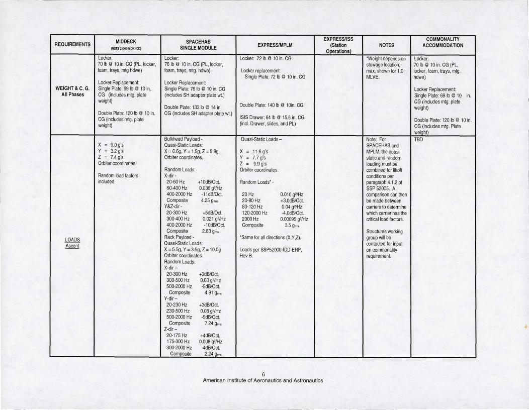
focus team addressed the concern of multiple payload requirements specifications for the various platforms. This team, known as the Common Middeck/Subrack Payload Requirement Team, had a goal of developing a global payload requirements envelope for the Shuttle middeck, a SPACEHAB locker, an EXPRESS rack, and an EXPRESS transportation rack that transports payloads in the multi-purpose logistics module (MPLM). The team started off this challenging task by reviewing existing documentation and identifying the various requirements. The requirements were then categorized as to whether or not a common envelope could be defined applicable to each of the four platforms. The structural loads requirement is still in negotiation stages to determine whether a common envelope can be identified. The categorization included negotiations with each of the platform teams to determine the potential common envelope and whether this common envelope would satisfy the requirements of each of the platforms. The following table summarizes the categories . The determination on commonality was driven by the platform with the least flexibility. Table 2, at the end of this paper, is a matrix of all of the requirements listed above with the specifications for each platform. In most cases, the limiter that establishes the common subset is easily identified. For example, ascent and descent power is constrained by the power specifications for the Shuttle middeck area. The middeck
In Work Cannot Make Common Loads Vacuum Exhaust
CommandinQ and Data Downlink Video
Nitrogen Services
Table 1 Categorized Requirements
2 American Institute of Aeronautics and Astronautics
provides 28 +/- 4 VDC on 10 and 20 amp circuits with total available power at 400 watts (W). The SPACEHAB single module has additional DC circuits and a greater maximum total DC power available. Therefore, for ascent and descent power, the common accommodations between these two platforms is constrained by what can be provided by the middeck. An example where there is no commonality is the on-orbit vacuum exhaust. There is no vacuum exhaust capability in the Shuttle middeck, or the MPLM. Therefore , there is no commonality other than for the payload to not use on-orbit vacuum exhaust. Since this is not reasonable for many payloads, their design must take into account that they cannot have access to vacuum exhaust while their payload is located in the middeck or the MPLM.
Rationale
The common envelope is most useful to those payloads that will be transported to ISS by the Space Shuttle, transferred to ISS for on-orbit operations, and then returned on the Space Shuttle. In this scenario , the payload could be placed in the middeck, SPACEHAB single module, or the MPLM in an EXPRESS rack or EXPRESS transportat ion rack for ascent and descent. For on-orbit ISS operations, the payload is installed in an EXPRESS rack. While the payload designer may know the platforms their hardware will interface with at the beg inning of the design phase, the dynamic nature of the manifests may change their ascent and descent platforms multiple times before the hardware actually flies. Also, on-orbit anomalies may require transport of the hardware on an unanticipated platform . The benefit of designing hardware to an overall envelope is that it will be compatible with all of the platforms and the payload team will be minimally impacted by manifest adjustments or contingency situations. The downside to designing to an overall envelope is the increase in constraints, wh ich may decrease the operations flexibility of the hardware. The hardware will have to meet the most extreme conditions including the tightest power specifications and the largest swing in environmental temperature and pressure. Therefore, it is likely that the cost of the hardware and necessary resource accommodations such as mass will increase because of the additional design constraints . These tradeoffs will have to be made by each
3
payload team. With the matrix identifying the requirements for each platform, the payload team will have a gu ide available for comparison so that they can make the best choice for their payload. The matrix shown here is not a requirements document, and the payload developer must be aware that they will be required to verify their hardware against an Interface Control Document (ICO) they establish with the integrator of the platform they choose to use to perform science.
Summary
Since the payload developers that will benefit most from a set of common requirements across platforms are EXPRESS users, the common requirements envelope is being incorporated in the EXPRESS rack 100, SSP 52000-IOO-ERP. Payload developers performing science on the ISS design to the requirements in SSP 52000-IDO-ERP. Th is approach maximizes manifest opportunities for payload developers. The payload developer who plans on performing science on other platforms will have the option to design to a specific platform or to use SSP 52000-IOD-ERP for their design requirements . The advantage of using SSP 52000-IDD-ERP is the payload will be able to perform science on all platforms and minimize reworking verification products . As mentioned earlier, a unique ICD will be developed between the integrator of the platform and the payload developer based on the platform's requirements . The payload developer wi ll have to compare the options and determine the best approach for their hardware, operat ions, and budget .
American Institute of Aeronautics and Astronautics
Acronyms
DC direct current
EXPRESS EXpedite the PRocessing of Experiments to Space Station
EMI electromagnetic interference
ICD Interface Control Document
IDD Interface Definition Document
ISS International Space Station
ISSP International Space Station Program
JSC Lyndon B. Johnson Space Center
MPLM Multi-Purpose Logistics Module
MSFC George C. Marshall Space Flight Center
NASA National Aeronautics and Space Administration
NSTS National Space Transportation System
SSP Space Shuttle Program
USA United States of America
VDC volts direct current
W watts
4 American Institute of Aeronautics and Astronautics
REQUIREMENTS MIDDECK SPACEHAB EXPRESSlMPLM
EXPRESS/ISS NOTES COMMONALITY
(NSTS 21eoo-MDK-IOO) SINGLE MODULE (Station Operations) ACCOMMODATION DC Power: DC Power: No power available to Payload total power DC Power: 28 ±4VDC 28± 4VDC payloads. available is for the entire 28 ±4VDC 10/20 Amp circuits Rack EPSU DC Circuits - carrier. Experiment 10/20 Amp Circuits
3SA, 1SA, 10A, SA. allocation available is Locker DC Circuits -SA, 3A dependent on the mission 400W max. total DC power
POWER complement. due to limited cooling Ascent!Descent Total Available Power: Total Available Power: available.
400W max. total DC 690W max. total DC power in single power in MD due to module due to limited cooling available. No AC available limited cooling available. ~ . . -- . .. - - -.- ----. --
No AC available No AC available MPLM-
No power DC power DC Power - No power provided to DC Power DC Power: 28 ±4VDC 28 ± 4VDC payloads. 28 + 1.S/-3.0VDC 28 + 1/S/-3.0VDC 10/20 Amp circuits Rack EPSU DC Circuits - S, 10, 1S, 20A services. 1 0120Amp circuits
3SA, 1SA, 1 OA, SA. Total Available Power: Locker DC Circuits - SA, 3A Total Available Power: NoAC power
1400 W w/o new power 20ooW/rack max. (may be panel Total Available Power limited by thermal cooling Total Available DC Power:
1900 W with new power 1400W max. (31S0W with 2nd Orbiter restrictions) 1OO0W per rack with nominal panel feed) Nominal power per payload 11SW per payload-locker
11SW DC per payload-locker mounted :::;1 SOW. mounted or replacement. POWER or replacement Max. power per payload On-Orbit 1OO0W per rack SooW.
AC Power AC Power - 690 VA Max Total AC Power 11S ± S V RMS, 400 Hz 11SVrms, 400 Hz, 3o, 120· Not available 3 phase, 1200 displacement
displacement PF: 0.7 lagging to 0.9 leading 300 VA, total capability o balance: <1S% of total load
11SW @ 11SVAC per payload
Note: All above negotiable on mission-by-mission basis.
I Double Plate: 133 1b @ 14 in. weight) Double Plate: 120 Ib @ 10 in. CG (includes SH adapter plate wt.)
ISIS Drawer: 64 Ib @ 15.6 in. CG CG (includes mtg. plate Double Plate: 120 Ib @ 10 in. weight) (inct. Drawer, slides, and PL) CG (includes mtg. Plate
weioht) Bulkhead Payload - Quasi-Static Loads - Note: For TBD
X = 9.0 g's Quasi-Static Loads: SPACEHAB and Y = 3.2 g's X = 6.6g, Y = 1.5g, Z = 5.9g X = 11.6 g's MPLM, the quasi-Z = 7.4 g's Orbiter coordinates. Y = 7.7 g's static and random Orbiter coord inates. Z = 9.9 g's loading must be
Random Loads: Orbiter coordinates. combined for liftoff Random load factors X-dir- conditions per included. 20-60 Hz +10dB/Oct. Random Loads' - paragraph 4.1.2 of
60-400 Hz 0.036 g2IHz SSP 52005. A 400-2000 Hz -11dB/Oct. 20 Hz 0.010 g2IHz comparison can then Composite 4.25 g= 20-S0 Hz +3.0dB/Oct. be made between
Y&Z-dir- SO-120Hz 0.04 g2IHz carriers to determine 20-300 Hz +5dB/Oct. 120-2000 Hz -4.0dB/Oct. which carrier has the 300-400 Hz 0.021 g2IHz 2000 Hz 0.00095 g2IHz critical load factors. 400-2000 Hz -10dB/Oct. Composite 3.5 gnns Composite 2.S3 g"", Structures working
LOADS Rack Payload - 'Same for all directions (X,Y,Z). group will be
Ascent Quasi-Static Loads: contacted for input X = 5.5g, Y = 3.5g, Z = 10.0g Loads per SSP52oo0-IDD-ERP, on commonality Orbiter coordinates. Rev B. requirement. Random Loads: X-dir-20-300 Hz +3dB/Oct. 300-500 Hz 0.03 g2IHz 500-2000 Hz -5dB/Oct.
(NSTS 21()()O.l,1OK~DO) SINGLE MODULE (Station Operations) ACCOMMODATION Bulkhead Payloads Note: Random loading TBD
X = 6.25 g's X = 9.5 g's X = 9.5 g's not applicable for descent Y = 2.50 g's Y = 2.50 g's Y = 5.4 g's conditions. Z = 12.5 g's Z = 9.00 g's Z = 12.5 g's
On-Orbit C02 PP: TBD depending on EVA constraints. 02 max: 25.9% C02 PP: TBD
EMVEMC Comparable Comparable Comparable Comparable Will consult EME panel TBD All Phases for commonality
Passive air cooling: Passive air cooling: Not required - no power available EXPRESS rack and Passive air cooling: 60W max. per single locker for payload operation. Middeck lockers designed
60W max. per single payload . for rear breathing forced 60W max. per single locker payload air cooling. locker payload
Cabin discharge: SPACEHAB can provide
Cabin discharge: Front breathing, 120F max. air rear breathing on a case Cabin discharge:
Front breathing, non- outlet, PD provides air circ. hdwe. by case basis. Front breathing, non-
ducted, PL provided fan , SH rack provided cooling via SPACEHAB can provide ducted, PL provided
PAYLOAD max. air out temp. 120F. RSCS fan , max. air out temp. water cooling via pump THERMAL package to both racks 120F. CONTROL Avionics Bay: and lockers
Ascent!Descent Ducted cooling, PL 400W max. power for provided fan , rear Middeck maximum all middeck items breathing, discharge to
690W total max. cooling for cooling capability is allowed due to cooling avionics bays 1, 2, 3A. different for each bay. limitations.
allowed in the cabin due to 105 CFM max. air flow per rack. through 6.2.1.5.3. for
cooling limitations. cooling capability for each MPLM-
bay. No requirement, no power.
-- . _-
7 American Institute of Aeronautics and Astronautics
REQUIREMENTS MIDDECK SPACEHAB EXPRESSIMPLM
EXPRESS/ISS NOTES
COMMONALITY (NSTS21~0!(~OOJ SINGLE MODULE (Station Operations) ACCOMMODATION
Cabin discharge: 1400W surface air Not applicable. No Avionics Air Assembly: EXPRESS rack and Middeck Max. air cooling: 1200W for Non-ducted PL provided fan , cooling. power provided to 15 ±3CFM total air available lockers designed for rear payloads. max. air out temp. 120F. payloads. per locker position. breathing forced air cooling.
2000 W Rack suction 65-B5F - inlet air 120F max. outlet air Avionics Bay: cooling 120F max. - outlet air (Air Rear breathing possible on SH temperature. Ducted cooling, PL provided temp. can vary depending on for lockers at the bulkhead; fan , rear breathing , discharge 60W per locker - payload heat load). selective placement required to PL to provide intemal fan. to avionics bays 1, 2, 3A. passive cooling. Max. air cooling of 1200W for prevent warm air suction into
PAYLOAD payloads. adjacent locker payloads. Max.
THERMAL 1500-2000W max. heat load 120F max. exhaust Payloads to provide internal cooling in this configuration is Passive cooling: 60 W per
CONTROL to cabin. air. temperature for fan for air flow. TBD. locker
I Passive cooling: BOW max. (Limited to $2 payloads). MPLM: per single payload. 61-73F - inlet water
120F max. - outlet water. No requirement, no power.
Combined payload cooling (air and water) not to exceed 2OO0W per rack.
VACUUM Not available. Not available. Not available. Not available. EXHAUST
AscentlDescent Not available. One Experiment Vent Not available. Available to each rack on Not available.
Value (EVV) Available shared , time-lined basis. Gases for Experiment Shared only; flow control and isolation usage. provided by payload.
VACUUM System available to EXHAUST locker or rack On-Orbit payloads on shared,
time-lined basis. Gases only; flow control and isolation Ilrovided by payload.
COMMANDING Not Available Not Available Not available Not available. (uplink)
DATA (downlink) AscentlDescent
- - - --
8 American Institute of Aeronautics and Astronautics
REQUIREMENTS MIDDECK SPACEHAB EXPRESSlMPLM
EXPRESSIISS NOTES
COMMONALITY (NSTS 21~DK,DOI SINGLE MODULE (Station Operations) ACCOMMODATION
Available from a DMU provides serial, analog, and None Interfaces per rack All Spacehab payload inpuVoutput TBD PGSC via the OCA discrete signal interfaces to the payload. payload:' data is via the Data Management system. The total number of DMU inputs and Unit (DMU) through bulkhead
outputs available to a particular payload 1- RS422 mounted experiment connector will be determined on a mission by panels mission basis. Racks: 1 - Ethemet
16 (DILs) 12 (DIHs) 8 (DOHs) 32 (Als) • Data interfaces of the EXPRESS also two serial DMU channels are 2 -Analog" rack RIC/SSPCM, the Middeck available at each rack location. system, and the Spacehab DMU Bulkhead mounted Payloads: 3 - Discrete" are not compatible. 72 (DILs) 56 (DIHs) 24 (DOHs) 104 (Als) and 8 serial DMU channels .. Routed through the SSPCM RS232 via (serial converter unit)
• All locker mounted payload input/output data is via the Data
COMMANDING Management Unit (DMU) through (uplink) bulkhead mounted experiment
DATA (downlink) connector panels in the Single On-Orbit Module. The EDSMU could be
made available. Will state requirement capabilities in the
RDM section later.
• DMU & EXPRESS rack Rack Interface Controller (RIC) interface characteristics are not compatible.
VIDEO Not Available Not Available Not Available Not Available Not available. AscentlDescent
Standard video Video Switching Unit (VSU) None 1 - Video (2 for ISIS Not available. downlink available. 8 unbalanced (single ended) inputs. The drawer payload)
VSU provides one balanced output to VIDEO the Orbiter CCTV system and one
On-Orbit unbalanced output is available as an input to a video digitizer/compressor provided by SPACEHAB. Two aux.outs . for attaching LCD monitors.
9 American Institute of Aeronautics and Astronautics
l
REQUIREMENTS MIDDECK SPACEHAB EXPRESSIMPLM
EXPRESSIISS NOTES COMMONALITY
(NSTS 21000-MDK~DO) SINGLE MODULE (Station Operations) ACCOMMODATION NITROGEN Not Available Not Available Not Available Not available.
Ascent!Descent
NITROGEN Not available. None None 12 Ibmlhr to rack and then to Not available.
NOISE NASA Std 145A in NSTS 4.7.2.2 & Table 4-X . requirements,
08080-1 - Environment - therefore the ISS
On-orbit; Intermittent requirement is the
payload generated noise controlling factor
limits.
PFE port required for actuve Two smoke sensors in Air None, not powered. No PFE port required for PFE port required for payloads. Mixing Box. payloads that interface to the active payloads.
rack AAA cooling loop. -_ . . _--- ------ ---
Ten Halon Bottles (6% vol. MPLM-
FIRE Concentration at 14.5 psia) Sealed container payloads do No requirement, no
PROTECTION not require a PFE port. power.
1 hand held fire extinguisher
2 SEBs units
Materials Envelope Worst Case From All Carriers
10 American Institute of Aeronautics and Astronautics