AIRCRAFT ACCIDENT REPORT 6/2008 Air Accidents Investigation Branch Department for Transport Report on the serious incident to Hawker Siddeley HS 748 Series 2A, registration G-BVOV at Guernsey Airport, Channel Islands on 8 March 2006 This investigation was carried out in accordance with The Civil Aviation (Investigation of Air Accidents and Incidents) (Guernsey) Order 1998
Transcript
AIRCRAFT ACCIDENT REPORT 6/2008
Air Accidents Investigation Branch
Department for Transport
Report on the serious incident toHawker Siddeley HS 748 Series 2A, registration G-BVOV
at Guernsey Airport, Channel Islandson 8 March 2006
This investigation was carried out in accordance withThe Civil Aviation (Investigation of Air Accidents and Incidents) (Guernsey) Order 1998
Printed in the United Kingdom for the Air Accidents Investigation Branch
Published with the permission of the Department for Transport (Air Accidents Investigation Branch).
This report contains facts which have been determined up to the time of publication. This information is published to inform the aviation industry and the public of the general circumstances of accidents and serious incidents.
Extracts can be published without specific permission providing that the source is duly acknowledged.
Published 21 August 2008
iii
RECENT FORMAL AIRCRAFT ACCIDENT AND INCIDENT REPORTSISSUED BY THE AIR ACCIDENTS INVESTIGATION BRANCH
THE FOLLOWING REPORTS ARE AVAILABLE ON THE INTERNET AThttp://www.aaib.gov.uk
4/2007 Airbus A340-642, G-VATL September 2007 en-route from Hong Kong to London Heathrow on 8 February 2005.
5/2007 Airbus A321-231, G-MEDG December 2007 during an approach to Khartoum Airport, Sudan on 11 March 2005.
6/2007 Airbus A320-211, JY-JAR December 2007 at Leeds Bradford Airport on 18 May 2005.
7/2007 Airbus A310-304, F-OJHI December 2007 on approach to Birmingham International Airport on 23 February 2006.
1/2008 Bombardier CL600-2B16 Challenger 604, VP-BJM January 2008 8 nm west of Midhurst VOR, West Sussex on 11 November 2005.
2/2008 Airbus A319-131, G-EUOB January 2008 during the climb after departure from London Heathrow Airport on 22 October 2005. 3/2008 British Aerospace Jetstream 3202, G-BUVC February 2008 at Wick Aerodrome, Caithness, Scotland on 3 October 2006.
4/2008 Airbus A240-214, G-BXKD February 2008 at Runway 09, Bristol Airport on 15 November 2006.
5/2008 Boeing 737-300, OO-TND April 2008 at Nottingham East Midlands Airport on 15 June 2006.
iv
Department for TransportAir Accidents Investigation BranchFarnborough HouseBerkshire Copse RoadAldershotHampshire GU11 2HH
June 2008
Mr Geoffrey RowlandThe Bailiff of Guernsey
Dear Sir
I have the honour to submit the report by Mr R D G Carter, an Inspector of Air Accidents, on the circumstances of the serious incident to Hawker Siddeley HS 748 Series 2A, registration G-BVOV, at Guernsey Airport, Channel Islands on 8 March 2006.
Yours sincerely
David KingChief Inspector of Air Accidents
v
Department for TransportAir Accidents Investigation BranchFarnborough HouseBerkshire Copse RoadAldershotHampshire GU11 2HH
June 2008
The Right Honourable Ruth KellySecretary of State for Transport
Dear Secretary of State
I have the honour to submit the report by Mr R D G Carter, an Inspector of Air Accidents, on the circumstances of the serious incident to Hawker Siddeley HS 748 Series 2A, registration G-BVOV, at Guernsey Airport, Channel Islands on 8 March 2006.
1 Factual Information .............................................................................................. 3
1.1 History of the flight ....................................................................................... 3
1.2 Injuries to persons .......................................................................................... 8
1.3 Damage to aircraft .......................................................................................... 8
1.4 Other damage ................................................................................................. 8
1.5 Personnel information ................................................................................... 91.5.1 Commander ...................................................................................... 91.5.2 First Officer ...................................................................................... 9
1.6 Aircraft information ..................................................................................... 101.6.1 General information ....................................................................... 101.6.2 Aircraft weight and centre of gravity ............................................. 111.6.3 Performance ................................................................................... 121.6.4 Brake system .................................................................................. 121.6.5 Other systems that provide additional braking ............................. 131.6.6 Enhanced Ground Proximity Warning System (EGPWS) ............. 141.6.7 Aquaplaning information .............................................................. 141.6.8 Maintenance information ............................................................... 14
1.8 Aids to navigation ........................................................................................ 161.8.1 Instrument Landing System (ILS) ................................................. 16
1.11 Flight Recorders .......................................................................................... 191.11.1 Available recordings ...................................................................... 191.11.2 Recorded data ................................................................................ 19
1.12 Incident site information .............................................................................. 20
vii
1.13 Medical and pathological information ......................................................... 21
1.14 Fire ............................................................................................................... 21
1.16 Tests and research ........................................................................................ 211.16.1 Maxaret tests .................................................................................. 21
1.17 Organisational and management information .............................................. 221.17.1 Regulatory oversight and previous investigations ......................... 22
2.1 General ......................................................................................................... 31
2.2 Condition of the runway .............................................................................. 31
2.3 Condition of the aircraft ............................................................................... 322.3.1 Flight data recorders ...................................................................... 32
AAIB Air Accidents Investigation Branchaal above airfield levelagl above ground levelamsl above mean sea levelAOC Air Operator’s CertificateATC Air Traffic Control ATIS Aeronautical Terminal Information
SystemCAA Civil Aviation AuthorityCAM Cockpit area microphonecm centimetres°C,F,M,T Celsius, Fahrenheit, magnetic, trueCRM Crew Resource ManagementCVR Cockpit Voice RecorderDA Decision AltitudeDH Decision HeightDME distance measuring equipmentEGPWS Enhanced GPWSFDR Flight Data RecorderFFPS Flight Fine Pitch Stopft feetGFPS Ground Fine Pitch StopGPS Global Positioning Systemhrs hours (clock time as in 12:00 hrs)ICAO International Civil Aviation
Conditionsin inch(es)IRE Instrument Rating ExaminerJAR Joint Aviation Requirementskg kilogram(s)km kilometre(s)kt knot(s)lb pound(s)LDA landing distance availableLDR landing distance requiredm metresMHz Mega Hertzmin(s) minutesmm millimetre(s)nm nautical mile(s)OPC Operator proficiency checkPAPI Precision Approach Path IndicatorPCU Propeller Control UnitPF Pilot flyingPNF Pilot not flyingpsi pounds per square inchQNH pressure setting to indicate elevation
above mean sea level
RFFS Rescue and Fire Fighting ServiceRVR runway visual rangeSOP Standard Operating ProcedureTAF Terminal Aerodrome ForecastTRE Type Rating ExaminerUK United KingdomUTC Co-ordinated Universal Time (GMT)VAT Threshold airspeedVCR Visual Control RoomVHF very high frequency
Registered Owner and Operator: Emerald Airways Limited
Aircraft Type and Model: Hawker Siddeley HS 748 Series 2A
Nationality: United Kingdom
Registration: G-BVOV
Place of Incident: Guernsey Airport, Channel Islands Latitude: 49°26’N Longitude: 002°36’W
Date and Time: 8 March 2006 at 1157 hrs All times in this report are UTC
Synopsis
This serious incident was notified to the Air Accidents Investigation Branch (AAIB) by ATC at Guernsey Airport shortly after the occurrence. Inspectors from the AAIB travelled to Guernsey and commenced the investigation later that day.
The following Inspectors participated in the investigation:
Mr R D G Carter Investigator-in-charge Mr P Taylor OperationsMr R J McMillan EngineeringMr P Wivell Flight Recorders
The aircraft was landing at Guernsey at the end of a two-sector cargo service from Coventry and Jersey. The Category I ILS approach on Runway 27 at Guernsey was flown in weather conditions that were poor but acceptable for making the approach and there was ample fuel on board for a diversion. The aircraft was seen to touch down between 400 and 550 metres from the ‘stop’ end of the runway and overran by some 145 metres onto the grass beyond the paved surface. There were no injuries.
�
Investigation by the AAIB revealed no aircraft or runway deficiencies to account for the overrun. During the final approach and landing there were substantial divergences from the company Operations Manual.
This operator had previously been the subject of close monitoring by the CAA over a sustained period and its Air Operator’s Certificate (AOC) was later suspended.
The investigation identified the following causal factors:
(i) The flight crew did not comply with the Standard Operating Procedures for a Category I ILS.
(ii) The commander’s decision to land or go around was delayed significantly beyond the intersection of the Decision Altitude and the ILS glideslope.
(iii) After landing, the crew did not immediately apply maximum braking or withdraw the flight fine pitch stops, as advised in the Operations Manual.
(iv) The operator’s training staff lacked knowledge of the Standard Operating Procedures.
The investigation identified the following contributory factor:
(i) Close monitoring by the CAA had not revealed the depth of the lack of knowledge of Standard Operating Procedures within the operator’s flight operations department until after this incident.
One Safety Recommendation is made to the CAA.
3
1 Factual Information
1.1 Historyoftheflight
The crew, who had not flown together before, reported for duty at the operator’s Coventry base at 0615 hrs for a two-sector cargo service to Jersey and on to Guernsey. The aircraft’s departure from Coventry was delayed because of work in progress on the runway and G-BVOV eventually took off at 0930 hrs. The crew had established that the weather conditions in the Channel Islands were poor and, as a result, had uplifted sufficient reserves of fuel to enable them to return to Coventry should they need to divert during the first sector to Jersey.
The flight to Jersey, on which the co-pilot was the pilot flying (PF), was uneventful and the aircraft successfully completed an ILS approach to Runway 27 at Jersey, during which the crew became visual with the runway at a height of about 800 ft aal. During the turnaround the larger part of the cargo was offloaded and G-BVOV was refuelled to 4,100 kg, enough for the flight to Guernsey and the aircraft’s following sector to Hamburg with a new crew.
Before G-BVOV departed from Jersey, the commander, who was the PF for the short, fifteen-minute flight to Guernsey, conducted a briefing for the ILS approach to Runway 27 at Guernsey. He advised the co-pilot to monitor the approach and, following the PNF ‘500 above’ challenge and response call, to look out and check for any visible signs of the approach lighting, while the commander continued to focus his attention on the flight instruments. The commander said that he would advise the co-pilot of any corrections he was making to the aircraft’s flight path. He also briefed that at the Decision Altitude (DA) of 540 ft amsl, one of the two would call “at minimums” and that the co-pilot should call “nothing seen” or “I have the lights”, as appropriate. If the co-pilot called “nothing seen”, the commander would initiate a go-around. During the investigation, the commander stated that at the DA the aircraft needed to be within a deviation of “one dot” on both the glideslope and localiser indications on the flight instruments, otherwise a go-around should be initiated.
The crew delayed their departure from Jersey because the Runway Visual Range (RVR) at Guernsey was less than the minimum 550 metres required for the planned ILS approach to Runway 27. Having made that decision, the visibility in Guernsey improved and the aircraft departed Jersey with 951 kg of freight. When G-BVOV was established in the cruise at 2,000 ft amsl the co-pilot checked the weather conditions at Guernsey, broadcast on the aerodrome’s Aeronautical Terminal Information Service (ATIS). At 1144 hrs ‘Information
4
Kilo’ gave the surface wind as 230º/21 kt, visibility 350 metres with the Runway 27 Runway Visual Range (RVR) 1,500 metres, moderate rain, fog, broken cloud below 100 feet agl, temperature 10ºC, dew point 9ºC and a QNH pressure setting of 1004 millibars. The ATIS transmission also advised that the runway surface was wet throughout its length and that ATC Low Visibility Procedures were in force. While the co-pilot was obtaining this information the commander was advised by ATC that a DHC-8 aircraft had just landed. With the RVR for Runway 27 greater than the minimum visibility required, the crew were able to continue with the planned ILS approach to Runway 27, but, because of the crosswind conditions, the commander had briefed that they would land with 22½º of flap, one stage less than the full 27½º of flap available, for greater roll control.
The crew were given radar vectors and the aircraft was established on the localiser at 9 nm with 15º of flap selected and the landing gear extended. They were instructed to transfer to the ATC tower frequency and, as G-BVOV intercepted the glideslope, they selected 22½º of flap. The aircraft was cleared to land and the crew were advised that the surface wind was 230º/18 kt. The VAT of 97 kt (speed crossing the threshold while landing), for a landing weight of 16,730 kg and flap setting of 22½º, had been confirmed during the cruise and the commander recalled that the aircraft’s speed was between 100 and 110 kt while they descended on the ILS.
During the approach the ATC tower controller continued to give the crew regular updates on the RVR as it reduced to 900 metres, then increased to 1,200 metres before decreasing back to 900 metres. They were also given updates on the surface wind, which varied in direction between 220º and 250º and between 15 kt and 22 kt. In the early stages of the descent, the commander noticed that he did not have to make much allowance for crosswind. However, towards the end of the approach he advised the co-pilot that he was having to allow for a drift to the right. The surface wind reported just before the landing was 230º/15 kt.
During the ILS approach the co-pilot recalled seeing a lateral deviation from the localiser of about ½ a dot. He made the ‘500 above’ challenge and response call, reminded the commander that the DA was 540 feet amsl and advised him that he was “LOOKING OUT”. Some 40 seconds after that the commander advised the co-pilot that the aircraft was slightly below the glideslope but correcting. A further 20 seconds later the Enhanced Ground Proximity Warning System (EGPWS) activated a GLIDESLOPE audio warning. There was no verbal challenge from the co-pilot. After another forty seconds, the CVR recorded a
5
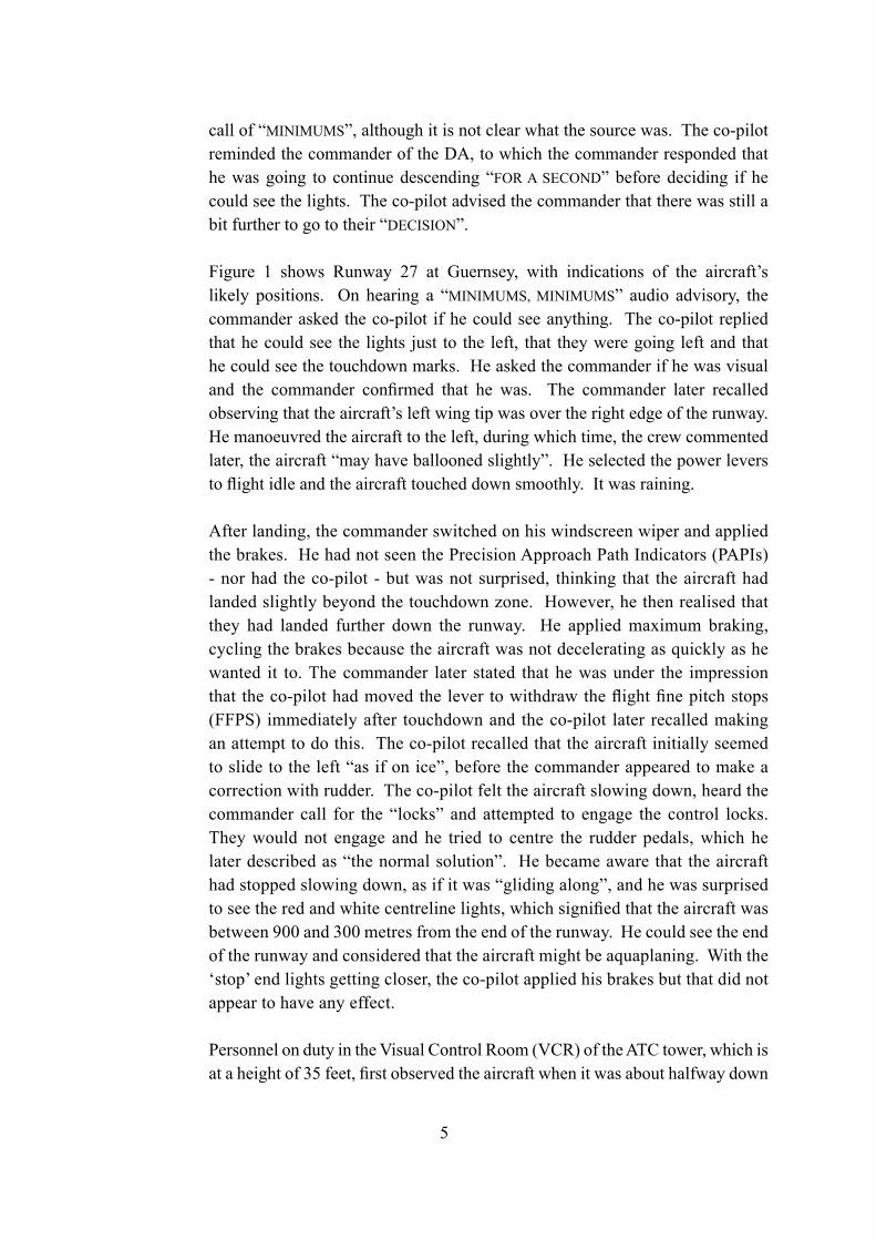
call of “MINIMUMS”, although it is not clear what the source was. The co-pilot reminded the commander of the DA, to which the commander responded that he was going to continue descending “FOR A SECOND” before deciding if he could see the lights. The co-pilot advised the commander that there was still a bit further to go to their “DECISION”.
Figure 1 shows Runway 27 at Guernsey, with indications of the aircraft’s likely positions. On hearing a “MINIMUMS, MINIMUMS” audio advisory, the commander asked the co-pilot if he could see anything. The co-pilot replied that he could see the lights just to the left, that they were going left and that he could see the touchdown marks. He asked the commander if he was visual and the commander confirmed that he was. The commander later recalled observing that the aircraft’s left wing tip was over the right edge of the runway. He manoeuvred the aircraft to the left, during which time, the crew commented later, the aircraft “may have ballooned slightly”. He selected the power levers to flight idle and the aircraft touched down smoothly. It was raining. After landing, the commander switched on his windscreen wiper and applied the brakes. He had not seen the Precision Approach Path Indicators (PAPIs) - nor had the co-pilot - but was not surprised, thinking that the aircraft had landed slightly beyond the touchdown zone. However, he then realised that they had landed further down the runway. He applied maximum braking, cycling the brakes because the aircraft was not decelerating as quickly as he wanted it to. The commander later stated that he was under the impression that the co-pilot had moved the lever to withdraw the flight fine pitch stops (FFPS) immediately after touchdown and the co-pilot later recalled making an attempt to do this. The co-pilot recalled that the aircraft initially seemed to slide to the left “as if on ice”, before the commander appeared to make a correction with rudder. The co-pilot felt the aircraft slowing down, heard the commander call for the “locks” and attempted to engage the control locks. They would not engage and he tried to centre the rudder pedals, which he later described as “the normal solution”. He became aware that the aircraft had stopped slowing down, as if it was “gliding along”, and he was surprised to see the red and white centreline lights, which signified that the aircraft was between 900 and 300 metres from the end of the runway. He could see the end of the runway and considered that the aircraft might be aquaplaning. With the ‘stop’ end lights getting closer, the co-pilot applied his brakes but that did not appear to have any effect.
Personnel on duty in the Visual Control Room (VCR) of the ATC tower, which is at a height of 35 feet, first observed the aircraft when it was about halfway down
6
Figure 1
Runw
ay 27 at Guernsey A
irport
7
the runway, at a height of approximately 50 feet. The aircraft then disappeared from view behind cloud. The ATC controller realised that the aircraft was not well placed for a landing but paused before calling the aircraft because he thought that the crew were probably busy. During that pause the airfield’s Rescue and Fire Fighting Service (RFFS) reported to ATC that they were “rolling”, having seen the aircraft land near the end of the runway with insufficient distance in which to stop.
The aircraft departed the end of the paved surface to the left of the centreline and immediately started to slow down. It continued straight ahead and stopped 145 metres beyond the end of the runway, before reaching the approach lighting for Runway 09 (Figure 2). The commander advised ATC of their position and ATC replied that the fire vehicles were on their way. A few seconds later, the crew acknowledged a request from ATC for them to contact the RFFS on 121.6 MHz. Neither of the crew was injured and they carried out the After Landing and Shutdown checks, during which they discovered that the flight fine pitch stops (FFPS) had not been withdrawn. They then disembarked the aircraft, inserted the landing gear safety pins and liaised with the RFFS.
Figure 2
G-BVOV at Guernsey Airport, 8 March 2006
8
Members of staff who were on duty with the RFFS subsequently provided details of where they recalled seeing the aircraft touch down. This placed the point of touchdown between 400 and 550 metres from the end of the paved surface on Runway 27. The incident occurred at 1157 hrs.
The engineer from the operator’s engineering organisation subsequently replaced two tyres and two Maxaret anti-skid units before the aircraft was ferried back to the UK. He reported that the aircraft’s performance during the landing in the UK was satisfactory.
An ‘abnormal landing’ check was carried out after the incident. This included an inspection of the flying controls and an inspection of the landing gear. The only damage to the aircraft was to the No 1 and No 3 tyres, and this was probably a result of the tyres hitting airfield lights. Both tyres were replaced. On the No 4 tyre there was an area where the surface appeared to have been affected by heating, but the tyre was not replaced.
1.4 Other damage
Five airfield lights were damaged and had to be replaced. Their location was as follows:
At the western end of the runway was a row of lights that marked the threshold for Runway 09 and the end of Runway 27. In this row of lights, three threshold lights and one runway end light were damaged.
140 metres from the western end of Runway 27 were nine lights that were part of the approach lighting to Runway 09. One of these lights was damaged.
9
1.5 Personnel information
1.5.1 Commander
Male, 59 yearsLicence: Airline Transport Pilot’s LicenceInstrument Rating: Valid until 30 April 2006Medical: Class One valid until 22 May 2006 with an operational multi-crew limitationFlying experience: Total all types 8,300hours Total on type 4,000 hours Last 90 days 60 hours Last 28 days 14 hours
The commander, who held the post of Deputy Chief Training Captain, had joined the company in 1995. He was a Type Rating Examiner (TRE) and an Instrument Rating Examiner (IRE) on the HS 748, and was also employed as a Crew Resource Management Instructor (CRMI) by the operator. The operator had assessed his performance as ‘exceptional’ during his last Operator Proficiency Check (OPC) and Line Check.
Previous rest period: The commander reported for duty following a rest period of 30 hours. Initially, he had been instructed to report for duty at 0330 hrs but the report time was delayed until 0615 hrs due to aircraft availability.
1.5.2 First Officer
Male, 40 yearsLicence: Commercial Pilot’s LicenceInstrument Rating: Valid until 15 October 2006Medical: Class One valid until 15 September 2006, with a requirement to wear corrective lenses and carry a spare set of spectaclesFlying experience: Total all types 988 hours Total on type 150 hours Last 90 days 91 hours Last 28 days 32 hours
The co-pilot had joined the company in September 2005 and finished his training on 26 November. Simulator training was not available for the 748 and this was the first time he had experienced IMC conditions to minimums on a landing
10
approach.
Previous rest period: The co-pilot reported for duty following a rest period of 55 hours 30 minutes.
1.6 Aircraft information
1.6.1 General information
The 748 aircraft was designed by the Avro company in the late 1950s as a 48-seat passenger aircraft. Early in the production run Avro was fully absorbed into Hawker Siddeley Aviation Ltd, and G-BVOV was a Series 2A variant manufactured in 1980. The aircraft was transferred to the operator in May 1995 and configured for cargo operations.
Figure 3 shows a photograph of G-BVOV on the apron.
Figure 3
G-BVOV - Hawker Siddeley HS 748 Series 2A
11
Manufacturer Hawker Siddeley Aviation LtdType HS 748 Series 2AAircraft Serial Number 1777Year of manufacture 1980Powerplants Two Rolls-Royce Dart 534-2 turboprop
enginesTotal airframe hours 22,110 at 8 March 2006Certificate of Airworthiness No. 045369/004Category Transport (Passenger) - Expiry 11 May 2007Issuing Authority United Kingdom CAARegistered Owner Emerald Airways LtdWingspan 30.02 metres
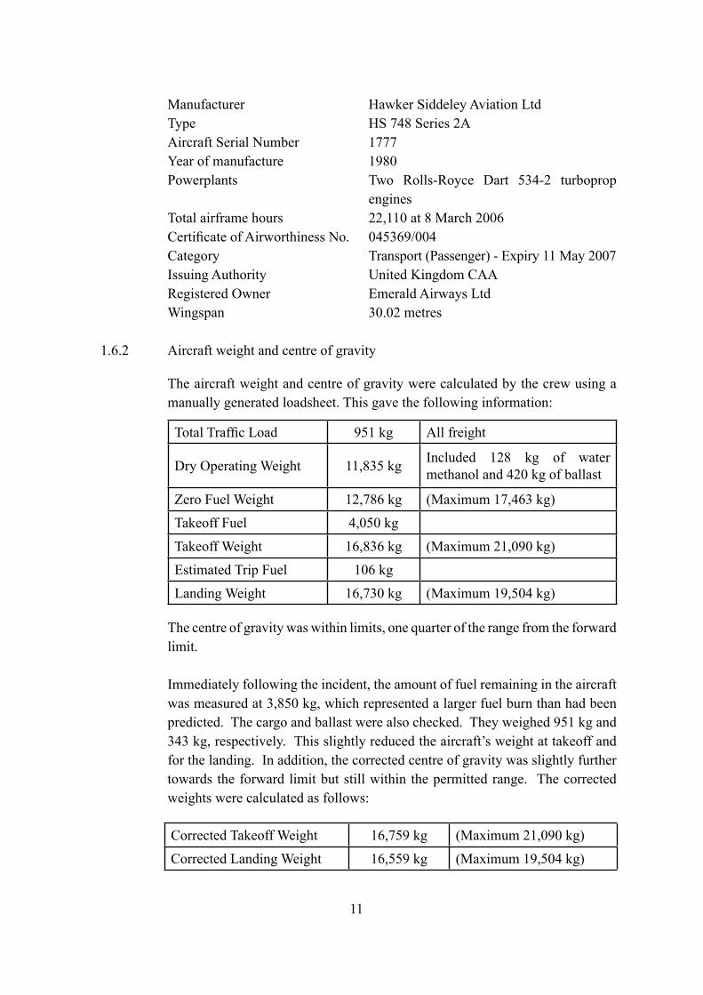
1.6.2 Aircraft weight and centre of gravity
The aircraft weight and centre of gravity were calculated by the crew using a manually generated loadsheet. This gave the following information:
The centre of gravity was within limits, one quarter of the range from the forward limit.
Immediately following the incident, the amount of fuel remaining in the aircraft was measured at 3,850 kg, which represented a larger fuel burn than had been predicted. The cargo and ballast were also checked. They weighed 951 kg and 343 kg, respectively. This slightly reduced the aircraft’s weight at takeoff and for the landing. In addition, the corrected centre of gravity was slightly further towards the forward limit but still within the permitted range. The corrected weights were calculated as follows:
Total Traffic Load 951 kg All freight
Dry Operating Weight 11,835 kg Included 128 kg of water methanol and 420 kg of ballast
Zero Fuel Weight 12,786 kg (Maximum 17,463 kg)
Takeoff Fuel 4,050 kg
Takeoff Weight 16,836 kg (Maximum 21,090 kg)
Estimated Trip Fuel 106 kg
Landing Weight 16,730 kg (Maximum 19,504 kg)
Corrected Takeoff Weight 16,759 kg (Maximum 21,090 kg)
Corrected Landing Weight 16,559 kg (Maximum 19,504 kg)
12
1.6.3 Performance
The aircraft manufacturer provided details of the required landing distance, from a height of 50 feet, and the landing ground run for the following conditions:
(The factored Landing Distance Required includes a safety margin of an extra 67%)
Landing Ground Run Distance (unfactored): 365 metres (1,196 feet)
Historical calculations have shown that if the propellers remain in flight fine pitch after landing then the Landing Ground Run Distance is increased by the order of 10%, a distance of 401 metres (1,315 feet) in this case. This unfactored figure does not contain allowances for operational circumstances, such as the actual runway friction coefficient, the amount of braking used by the pilot or when it was applied.
1.6.4 Brake system
There are two wheels fitted to each of the main gear legs. Each main wheel is fitted with a brake, making four brakes per aircraft. Maxaret units are fitted to each main wheel axle to provide anti-skid braking. Inside each Maxaret unit there is a flywheel and a valve and, as the wheel slows down at the start of a skid, the inertia of the flywheel causes the valve to open. The open valve connects the hydraulic pressure in the brake to return and hence the brake is released to stop the skid.
13
1.6.5 Other systems that provide additional braking
The HS 748 has two other systems that are normally used to decelerate the aircraft to complement the brake system; namely drag from the flaps and drag from suitably angled propeller blades.
Located at the trailing edge of each wing is an electrically-operated Fowler flap. The flaps extend rearwards and droop downwards to increase both lift and drag. Each flap has a full length tab which droops downwards in the LAND configuration only. The angles of the flap elements for the five configurations are shown in this table.
The engines are each fitted with a four-bladed propeller. The propeller pitch angle is changed by the propeller control unit (PCU). There is a mechanical stop in the PCU that is set at 18º pitch angle, and this stop, called the flight fine pitch stop (FFPS), prevents the blade pitch angle becoming too fine in flight. During the landing run the FFPS is removed to allow the blade pitch angle to ‘fine off’ to the Ground Fine Pitch Stop (GFPS) and this creates additional drag to assist in decelerating the aircraft.
Amber coloured warning lights for BELOW FFPS and FFPS REMOVED are located on both the left and right flight instrument panels.
An audible horn sounds if the FFPS is not withdrawn within 5 seconds of the nosewheel being on the ground during the landing roll. This is the same horn as the undercarriage indication horn, and the horn will cancel once the FFPS has been withdrawn.
The aircraft was fitted with an ILS system. There was no autopilot and no autothrottle fitted to the aircraft.
1.6.6 Enhanced Ground Proximity Warning System (EGPWS)
The aircraft was fitted with a Honeywell Mk VI EGPWS, part number 965-1190-020. The primary purpose of EGPWS is to reduce the risk of controlled flight into terrain. The system can provide many situational awareness cues and alerts for the crew. The functions pertinent to this investigation relate to the glideslope alerting function, the decision height triggered callout and the EGPWS recording capability.
When below 1,000 ft, a deviation of more than 1.3 dots below the glideslope will trigger a ‘soft’ “GLIDESLOPE” alert. There are other factors involved in this alert mode but they are not relevant to this event. A ‘hard’ alert is triggered by further deviation below the glideslope.
The EGPWS installation was designed to provide a “MINIMUMS MINIMUMS” callout when the decision height is reached. The trigger is a discrete input from the flight instruments that indicates whether the radio altitude is above or below the bugged decision height set by the crew.
The EGPWS records a rotating buffer of the key parameters it is using for its processes. When an alert is triggered, such as a glideslope alert, 20 seconds of data prior to the alert and a further 10 seconds are stored for later download and analysis. This type of recording is not triggered by standard events such as reaching the decision height.
The EGPWS also takes a ‘snapshot’ of position information during every takeoff and landing. In the case of the landing, this is triggered by the radio altitude reducing through 50 feet.
1.6.7 Aquaplaning information
The typical minimum aquaplaning speed for this aircraft type is around 75 kt1, based on normal tyre pressures.
1.6.8 Maintenance information
Examination of the maintenance records did not show any factors contributing to this incident. The ILS and ASI instruments were within their calibration dates.
1 Source – the operator’s Operations Manual.
15
1.7 Meteorological information
1.7.1 Aerodrome
An actual meteorological observation at Guernsey Airport recorded at 1157 hrs on 8 March 2003 gave the surface wind as 230º/20 kt, visibility 900 metres in light rain and drizzle with broken cloud on the surface and at 100 feet aal. The temperature was 10ºC and the dew point was 9ºC. The QNH was 1003.
The forecast weather for Guernsey, issued at 0902 hrs on 8 March 2006 in Aerodrome Forecast (TAF) format, was as follows:
Forecast for 8 March 2006 valid from 1000 hrs to 1900 hrs. Surface wind 230º/21 kt with a visibility of 2,500 metres in mist. Scattered cloud at 100 feet aal, broken cloud at 200 feet aal with a 40% probability of temporary fluctuations at any time, expected to last less than one hour in each instance, and in aggregate for less than half the period between 0900 hrs and 1400 hrs, visibility 500 metres in rain and drizzle with broken cloud on the surface. Becoming, at an unspecified time between 1300 hrs and 1600 hrs, visibility 6,000 metres with broken cloud at 900 feet aal. Becoming, at an unspecified time between 1600 hrs and 1900 hrs, surface wind 270º/30 kt gusting to 42 kt, visibility greater than 10 km and broken cloud at 1,400 feet aal.
1.7.2 Winds
After the incident, the Met Office assessed that the winds at 1,000 feet amsl and 2,000 feet amsl in the vicinity of Guernsey Airport would have been 250º/30 kt and 250º/50 kt, respectively.
16
1.8 Aids to navigation
1.8.1 Instrument Landing System (ILS)
Runway 27 is equipped with an Instrument Landing System (ILS) with the glideslope set to 3º. The system was ON and serviceable at the time of the incident. It was subsequently checked on 9 March 2006 and confirmed to be serviceable. The Distance Measuring Equipment (DME), co-located with the ILS, was also ON and serviceable.
At the DA (540 feet amsl), a displacement of one dot on the localiser indication on the flight instruments represented a lateral displacement of 46.4 metres from the centreline. Full-scale deflection on the localiser display on the flight instruments represented a lateral displacement from the centreline of 116.2 metres.
1.9 Communications
VHF communications between the crew and Guernsey Approach Control (128.65 MHz) and Guernsey Tower (119.95 MHz) were satisfactory. Conversation was recorded and a copy compact disc, with injected time signal, was provided to the investigation team.
1.10 Aerodrome information
1.10.1 Runway physical characteristics
Runway 27 at Guernsey is 1,463 metres (4,800 feet) in length and 45 metres (147.6 feet) wide and has a QDM of 271°M. The Landing Distance Available on Runway 27 is 1,453 metres and the overall slope, which is not uniform, is published as being 0.65% down. The threshold of the runway is at an elevation of 334 feet amsl. 275 metres west of the threshold the runway elevation is 333 feet amsl. It then descends to an elevation of 296 feet at a point 1,220 metres beyond the threshold before rising to an elevation of 303 feet amsl at the ‘stop’ end of the runway (1,463 metres). The runway surface is of asphalt except at the thresholds where the surface is of concrete.
1.10.2 Lighting
The runway is equipped with high-intensity coded centreline lights and five crossbar approach lights, Precision Approach Path Indicators (PAPIs) set at 3º and high-intensity threshold lights with high-intensity wing bars. At the time of the incident these were selected to 100% intensity. The runway has
17
elevated high-intensity white bi-directional edge lights, with low-intensity omni-directional components at 60 metre intervals, and high-intensity colour-coded centreline lights and red end lights. These were selected ON to an intensity setting of 100%.
One deficiency had been reported at 0540 hrs on the day of the incident, that being a centreline light at the Runway 09 threshold. The lighting was checked on 6 and 13 March, either side of the date of the incident, and no deficiencies were recorded.
1.10.3 Runway friction tests
The friction of the runway was tested on the day of the incident. The CAA publishes CAP 683 ‘The Assessment of Runway Surface Friction for Maintenance Purposes’, and for the type of equipment used to test the runway at Guernsey it specifies a ‘minimum friction level’ of 0.55, a ‘maintenance planning level’ of 0.63, and a ‘design objective level’ of 0.80 or greater. If the runway friction fails to meet the minimum friction level then the runway shall be notified as ‘may be slippery when wet’.
Standard friction tests are undertaken on dry runways under controlled conditions using ‘self-wetting’ measuring equipment. The testing on the day of the incident used a Griptester Mk1a and at the time of the test the runway was WET, and hence the test was not under controlled conditions. Thirty-six measurements were taken during twelve runs along the runway and the friction values ranged from 0.61 to 0.82. Five of the thirty-six friction results marginally failed to meet the maintenance planning level of 0.63 for which CAP 683 states that:
‘maintenance should be taken to restore the friction level, ideally to a value equal to or greater than the design objective level.’
On 7 May 2006 the runway was tested under controlled conditions and all thirty-six results exceeded the maintenance planning level. All the measurements in both tests were significantly higher than the critical minimum friction level of 0.55.
18
1.10.4 Runway inspection
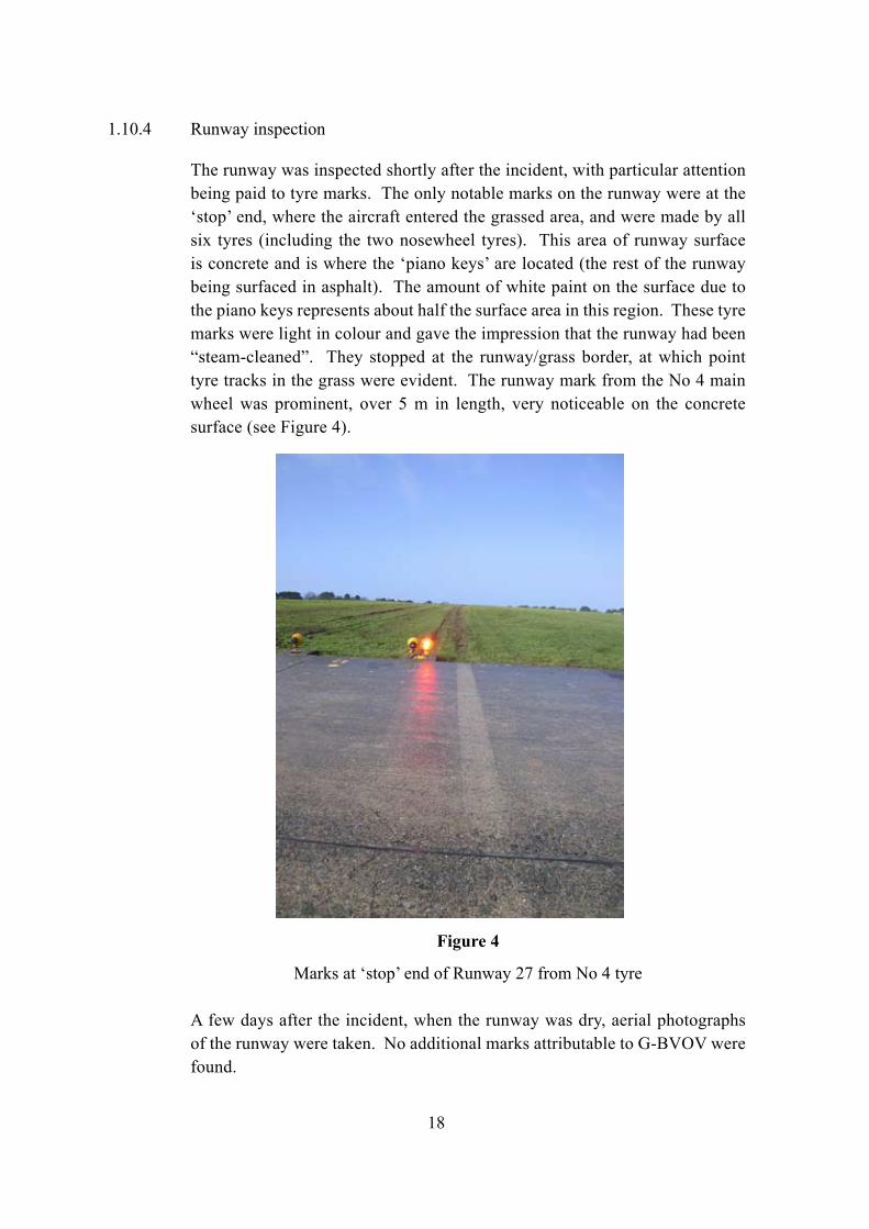
The runway was inspected shortly after the incident, with particular attention being paid to tyre marks. The only notable marks on the runway were at the ‘stop’ end, where the aircraft entered the grassed area, and were made by all six tyres (including the two nosewheel tyres). This area of runway surface is concrete and is where the ‘piano keys’ are located (the rest of the runway being surfaced in asphalt). The amount of white paint on the surface due to the piano keys represents about half the surface area in this region. These tyre marks were light in colour and gave the impression that the runway had been “steam-cleaned”. They stopped at the runway/grass border, at which point tyre tracks in the grass were evident. The runway mark from the No 4 main wheel was prominent, over 5 m in length, very noticeable on the concrete surface (see Figure 4).
Figure 4
Marks at ‘stop’ end of Runway 27 from No 4 tyre
A few days after the incident, when the runway was dry, aerial photographs of the runway were taken. No additional marks attributable to G-BVOV were found.
19
1.11 Flight Recorders
1.11.1 Available recordings
The aircraft was fitted with a 30-minute Cockpit Voice Recorder2 (CVR) and a 25-hour Flight Data Recorder3 (FDR). The CVR provided good recordings of the commander’s audio and the cockpit area microphone (CAM) but the recording of the co-pilot’s channel was very poor. This did not significantly affect this investigation. However, the FDR recording was of a very poor quality and did not include the incident flight.
Data was retrieved from Jersey secondary radar and the EGPWS fitted to the aircraft (section 1.6.6).
The following description of the incident flight is formed from an amalgamation of the different sources of recorded data and is illustrated in Figure 1. All times quoted are approximate and referenced to UTC.
1.11.2 Recorded data
The CVR recording provided the voice data for the ‘History of the flight’ in this report (section 1.1).
As described in section 1.1, at 1156 hrs the commander noted that they were slightly low on the glidepath and this was shortly followed by the ‘soft’ EGPWS “GLIDESLOPE” alert. At the time, radio altitude of the aircraft was between 547 ft and 538 ft and the aircraft had a CAS of 110 kt, was level in pitch and had 4º of right roll. In the 10 seconds of EGPWS recorded data after the alert was triggered, the deviation below the glidepath was reduced and the CAS reduced to 100 kt.
At the point the co-pilot reported the runway on the left, the radar data also indicated that the aircraft was to the right of the runway as it passed the runway threshold (Figure 1). 10 seconds after the “MINIMUMS MINIMUMS” call the commander stated that he had “GOT IT”, and 9 seconds later the aircraft touched down. At least 14 seconds had elapsed between the co-pilot seeing the touchdown marks pass and the aircraft touching down.
The EGPWS recorded a ‘snapshot’ position triggered by transitioning through a radio height of 50 ft. The snapshot included a GPS position which was
2 A Loral / Fairchild A100, part number 93-A100-30.3 A Plessey PV1584D, part number 650/1/14040/004.
20
596 metres beyond the threshold of Runway 27, with 867 metres to go. Whilst the radar data only recorded altitude in hundreds of feet, it was consistent with the 50 ft/GPS point. The radar data, allowing for reasonable errors, indicated that during the two radar sweeps after passing the runway threshold, the aircraft had a ground speed of 100 kt ±7 kt. The average ground speed for the last minute of radar track was 97 kt.
As reported in section 1.1, shortly after the aircraft touched down, the commander called for “LOCK” and the co-pilot responded that the “LOCKS” would not go in. A horn started sounding approximately 3 seconds after the call for “LOCK”. A short while later the commander communicated that the aircraft had left the runway. The crew carried out the After Landing checks. When the item relating to the flight fine pitch stops was reached the horn was stopped and the commander identified that the “STOPS” was what he had wanted (referring to the flight fine pitch stops) and that this was a significant factor.
Spectrum analysis of the CAM did not yield any speed-related audio signatures or the point at which the aircraft left the runway. It was also not possible to provide an accurate assessment of the time or distance between the 50 ft point recorded by the EGPWS and the touchdown point apparent on the CVR recordings.
1.12 Incident site information
The aircraft had overrun the end of Runway 27 and had travelled 145 metres over grass from the end of the paved surface. The aircraft had stopped 15 metres from the localiser array and the tyre tracks over the wet ground were to the left of the runway centre line; the furthest distance that the nosewheels had tracked from the centreline was 12 metres.
Whilst mud and grass had been thrown up onto the aircraft there was no aircraft damage other than the deep cuts on the No 1 and No 3 tyres, which were subsequently replaced. On the No 4 wheel there was a shallow, 20 cm diameter scorch mark on the tyre treads, (Figure 5) however this was inspected and passed as serviceable. This scorched area was consistent with the marks found on the runway (section 1.10.4 and Figure 4) and were consistent with heating as a result of local aquaplaning; hence the ‘steam-cleaned’ appearance on the runway.
21
Figure 5
Marks on No 4 tyre
1.13 Medical and pathological information
Both members of the crew were uninjured.
1.14 Fire
The Fire Service response was prompt but there was no fire.
1.15 Survival aspects
There were no injuries.
1.16 Tests and research
1.16.1 Maxaret tests
On the HS 748 each main gear wheel has a Maxaret unit to provide anti-skid to the brake system, and these were tested on-aircraft shortly after the incident. Due to the lack of the correct test equipment the tests were not conclusive, but the Maxaret units from the No 1 and No 4 wheels were removed and replaced as ‘possibly not functioning correctly’.
22
The two Maxaret units were subsequently taken to the manufacturer and bench tested using the manufacturer’s normal overhaul test procedure. As a result of the tests it was concluded that:
‘both Maxaret units would have performed the anti-skid activity as required during braking.’
1.17 Organisational and management information
1.17.1 Regulatory oversight and previous investigations
This company operated 30 aircraft, of which 14 were HS 748s. As part of its safety oversight audit programme, the Civil Aviation Authority (CAA) carried out annual audits of the company in areas such as flight operations, ramp operations, management and quality systems.
In January 2000 the AAIB published a report (Aircraft Incident Report 1/2000) on incidents involving two of the operator’s HS 748 Series 2A aircraft, registrations G-BIUV and G-BGMO, which occurred on 6 June 1998. The report included a recommendation (Safety Recommendation No 99-62) which stated:
‘It is recommended that the CAA should review the effectiveness of its current AOC [Air Operator’s Certificate] Holder Oversight Programme. In particular, the CAA should determine whether there is a need to introduce additional methods of ensuring timely compliance with identified potentially safety-related shortcomings in the AOC Holder’s operations.’
The CAA undertook to conduct that review.
In August 2002 the CAA conducted an audit of this operating company and found several non-conformities, particularly with regard to the training system and the related roles carried out by the Chief Training Captain, Director of Operations and the Chief Executive. In response to these non-conformities, the Company Accountable Manager and Director of Operations stated that:
‘the culture of training will be addressed and changed and both would redress their actions in order to satisfy their terms of reference.’
23
The CAA re-inspected the company at the end of September 2002 and confirmed that these non-conformities had been addressed to their satisfaction. They also made the following comment:
‘the operator’s training system should be closely monitored to ensure that it is adequate and reflects the scale of the operation.’
During the CAA Annual Audit in February 2004, one of the non-conformances that was raised, which required remedial action within 30 days, was:
‘The CRM training observed did not meet an acceptable standard.’
The CAA’s AOC Annual Report on the Operator in March 2004, while recommending continuance of the AOC, included the comment that:
‘A further period of close supervision will be required…’
After the CAA’s Annual Audit of the operator in January 2005, the CAA commented that:
‘The operator’s management structure must be suitable for the scale and scope of the operation – this includes adequate oversight by post holders of their areas of responsibility. The operator should review management competencies and terms of reference when addressing these non-conformances.’
In April 2005 the CAA noted that they had expended:
‘considerable efforts with this operator but must continue monitoring closely while they [the operator] are reducing fleets and remain under financial pressure.’
The records also showed that the operator had had 27 serious incidents in the year 2004-2005.
Following a serious incident involving one of the operator’s British Aerospace ATP aircraft, registration G-JEMC, on 23 May 2005, the AAIB’s Aircraft Accident Report 1/2007 included amongst its findings that:
‘The flight crew did not comply with Standard Operating Procedures [SOPs] regarding checklist use and crew co-ordination.’
24
After a further CAA audit in August 2005, it was noted that:
‘The findings …. were an indication of a lack of control and supervision of the operation by the management and their ability to fulfil their responsibilities in respect of:-
The monitoring of flight safety standards
The allocation of responsibilities and duties and issuing instructions to individuals, sufficient for implementation of company policy and the maintenance of safety standards.
Evaluating the safety record of the company in order to avoid the development of undesirable trends.’
The findings prompted the following comments, by the CAA:
‘The management structure must be adequate for the scale and scope of the operation. The operator had promised a management restructure for some months. The evidence of this report suggests that the restructuring is now an urgent issue.’
A CAA Annual Audit was carried out on the operator in January 2006. At the end of the Findings it was commented that:
‘If these non-conformances are not adequately closed on time, consideration must be given to restricting or suspending the AOC on the grounds of the actual organisation to secure a safe operation in practice.’
In a letter to the operator, dated 3 February 2006, regarding temporary arrangements for implementing a revised organisational structure, outlined by the operator in November 2005, the CAA wrote advising that:
‘… the accepted temporary arrangements, covering the ill health of two of your post holders positions, come to an end on 14 February 2006.’
Also on 3 February 2006 the operator’s AOC was renewed by the CAA.
25
In a later letter, dated 17 February 2006, the CAA wrote to the operator regarding:
‘….failure to close CAA audit findings on or by the agreed timescale
‘…reluctance to engage fully with the CAA and respond to some requests and deadlines.’
The operator was given until 27 February 2006 to respond to the CAA regarding non-conformances raised during recent CAA audits, which included an Operator Competency Check, a Manuals Check and a Ramp Check, and the implementation of a revised organisational structure. The operator was advised that failure to do so might result in restrictions being placed upon their AOC.
From 20 to 24 March 2006, the CAA carried out an audit of the operator’s flight crew training, across all their fleets. This audit had been previously scheduled and was not prompted by the serious incident to G-BVOV on 8 March. One of the non-conformances raised stated:
‘There was no oversight of the standards of the training and checking by the operator, as evidenced by the TRE’s lack of knowledge of SOPs.’
As a result of this audit, the CAA restricted the operator’s AOC to six months validity and removed their approval of the operator’s recurrent training and checking programme, required under JAR-OPS 1.965(a)(2), pending a suitable action plan, by 10 April 2006, to address the systemic failures identified by the audit.
The operator could not satisfy the CAA that it was able to appreciate the underlying causes of the systemic failures and put into place effective remedial action. Consequently, the CAA concluded that the operator was unable to secure a safe operation. Therefore, on 4 May 2006, the CAA suspended the operator’s AOC. The company effectively ceased trading and the operator’s AOC was revoked at the receiver’s request on 7 August 2006.
26
1.18 Additional information
1.18.1 Flight crew procedures
Part A of the operator’s Operations Manual stipulated the Standard Altimeter Calls to be used by the flight crew during a flight. The appropriate challenge and response calls for an ILS approach were as follows:
The procedures then included the advice:
‘If a challenge is missed, the other pilot shall make it and the first challenging pilot in the tables above will respond.’
Also, PNF was instructed to issue a verbal challenge to PF if the aircraft’s flight path deviated from the localiser or glideslope by one dot or more, as shown on the flight instruments, saying “LOCALISER” or “GLIDESLOPE”, as appropriate. In response, PF was required to say “CORRECTING” and take visible and effective corrective action. If a second challenge was required and not actioned and simultaneously corrected, PNF was instructed to take control, saying “I HAVE CONTROL”.
One dot deviation on the localiser indication on the flight instruments represented a lateral deviation of 1° from the localiser centreline. Full scale deflection on the glideslope and localiser indications equated to 2.5 dots.
The Operations Manual also defined an ILS approach as a precision approach and details of the visual references required for such an approach to continue below the DA (Decision Height (DH)) were given as:
‘No pilot may continue a precision approach below a DH [DA] … unless at least one of the following visual references for the intended runway is distinctly visible to, and identifiable by the pilot.
‘These may be:
i) elements of the approach lighting system;
ii) the threshold, or its markings, lights or identification lights;
iii) the visual glideslope indicator(s);
iv) the touchdown zone, zone markings or zone lights; or
v) the runway edge lights.’
This reflected the guidance given in the Joint Aviation Requirements manual JAR-OPS 1, entitled ‘Commercial Air Transportation (Aeroplanes)’.
With regard to the use of the radio altimeter (‘rad alt’) during a category I ILS, the Operations Manual stated:
‘They must not be used for CAT I minima, or for alert of such approaching minima. Therefore, the practice of setting RAD ALT to CAT 1 DH [Decision Height] is prohibited.’
1.18.2 Landing procedures
The Operations Manual advised that speeds used during the approach should be such that the correct threshold speed, VAT, could be achieved. VAT speeds were based on light winds and moderate turbulence. Crews were advised that, in more severe conditions, the target speeds should be increased by 1/3 of the gust factor to a maximum of 15 kt. VAT + 15 kt equated to the maximum threshold speed indicated in the manufacturer’s flight manual, above which the risk of exceeding the scheduled landing field length was unacceptably high.
For landing, the Operations Manual stated that both ‘Landing Flap 27½º or Approach Flap 22½º’ were available, but it advised that:
‘use of 22½º flap for landing results in a less restrictive WAT curve being obtained due to the improved climb performance in a baulked landing, but the associated landing distance is thereby increased.’
28
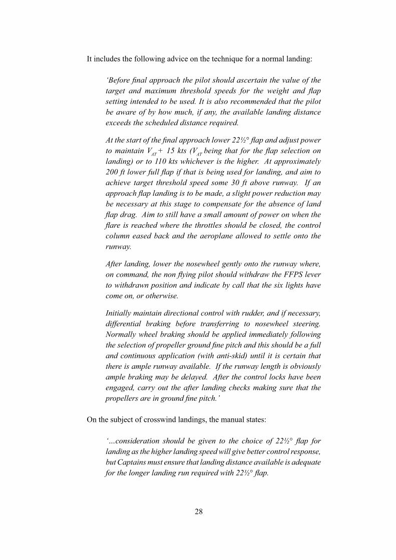
It includes the following advice on the technique for a normal landing:
‘Before final approach the pilot should ascertain the value of the target and maximum threshold speeds for the weight and flap setting intended to be used. It is also recommended that the pilot be aware of by how much, if any, the available landing distance exceeds the scheduled distance required.
At the start of the final approach lower 22½° flap and adjust power to maintain VAT + 15 kts (VAT being that for the flap selection on landing) or to 110 kts whichever is the higher. At approximately 200 ft lower full flap if that is being used for landing, and aim to achieve target threshold speed some 30 ft above runway. If an approach flap landing is to be made, a slight power reduction may be necessary at this stage to compensate for the absence of land flap drag. Aim to still have a small amount of power on when the flare is reached where the throttles should be closed, the control column eased back and the aeroplane allowed to settle onto the runway.
After landing, lower the nosewheel gently onto the runway where, on command, the non flying pilot should withdraw the FFPS lever to withdrawn position and indicate by call that the six lights have come on, or otherwise.
Initially maintain directional control with rudder, and if necessary, differential braking before transferring to nosewheel steering. Normally wheel braking should be applied immediately following the selection of propeller ground fine pitch and this should be a full and continuous application (with anti-skid) until it is certain that there is ample runway available. If the runway length is obviously ample braking may be delayed. After the control locks have been engaged, carry out the after landing checks making sure that the propellers are in ground fine pitch.’
On the subject of crosswind landings, the manual states:
‘…consideration should be given to the choice of 22½° flap for landing as the higher landing speed will give better control response, but Captains must ensure that landing distance available is adequate for the longer landing run required with 22½° flap.
29
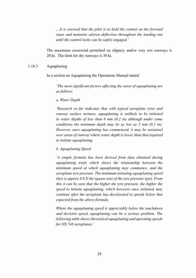
…It is stressed that the pilot is to hold the control on the forward stops and maintain aileron deflection throughout the landing run until the control locks can be safely engaged.’
The maximum crosswind permitted on slippery and/or very wet runways is 20 kt. The limit for dry runways is 30 kt.
1.18.3 Aquaplaning
In a section on Aquaplaning the Operations Manual stated:
‘The most significant factors affecting the onset of aquaplaning are as follows:
a. Water Depth
‘Research so far indicates that with typical aeroplane tyres and runway surface textures, aquaplaning is unlikely to be initiated in water depths of less than 6 mm (0.2 in) although under some conditions the minimum depth may be as low as 3 mm (0.1 in). However, once aquaplaning has commenced, it may be sustained over areas of runway where water depth is lower than that required to initiate aquaplaning. b. Aquaplaning Speed
‘A simple formula has been derived from data obtained during aquaplaning trials which shows the relationship between the minimum speed at which aquaplaning may commence, and the aeroplane tyre pressure. The minimum initiating aquaplaning speed (kts) is approx 8.6 X the square root of the tyre pressure (psi). From this it can be seen that the higher the tyre pressure, the higher the speed to initiate aquaplaning, which however, once initiated, may continue after the aeroplane has decelerated to speeds below that expected from the above formula.
Where the aquaplaning speed is appreciably below the touchdown and decision speed, aquaplaning can be a serious problem. The following table shows theoretical aquaplaning and operating speeds for HS 748 aeroplanes.’
30
c. Tyre Tread Design and Condition
A multi tread with grooves of adequate dimensions to give good drainage tends to relieve the hydrodynamic pressure and to increase the contact pressure between the tyre and the runway. With such a tread the speed and minimum water depth for the onset of aquaplaning will be increased.’
‘The ILS obstacle clearance surfaces assume that the pilot does not normally deviate from the centre line more than half a scale deflection after being established on track. Thereafter the aircraft should adhere to the on-course, on-glide path/elevation angle position since a more than half course sector deflection or a more than half course fly–up deflection combined with other allowable system tolerances could place the aircraft in the vicinity of the edge or bottom of the protected airspace where loss of protection from obstacles can occur.’
Aeroplane Type
Typical Tyre Pressure
Calculated Aqua. Speed
(Main Wheels)V1 Touchdown
Speed
HS 748 75 75 97 87
31
2 Analysis
2.1 General
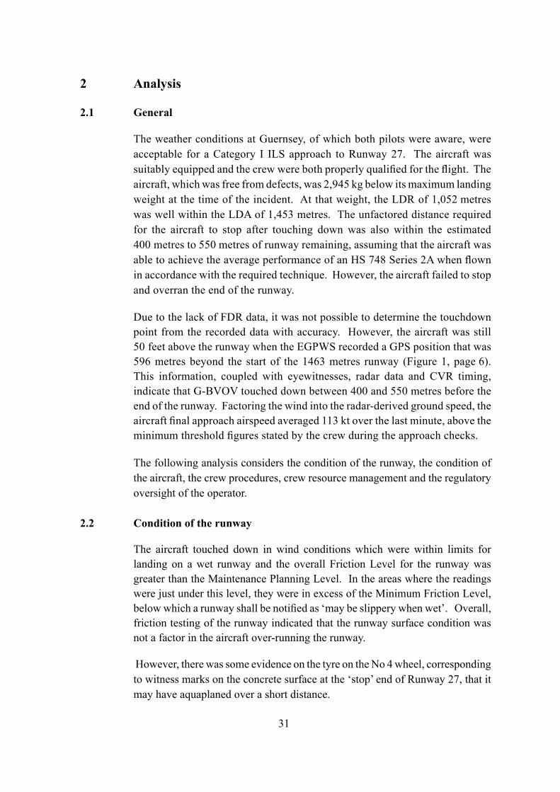
The weather conditions at Guernsey, of which both pilots were aware, were acceptable for a Category I ILS approach to Runway 27. The aircraft was suitably equipped and the crew were both properly qualified for the flight. The aircraft, which was free from defects, was 2,945 kg below its maximum landing weight at the time of the incident. At that weight, the LDR of 1,052 metres was well within the LDA of 1,453 metres. The unfactored distance required for the aircraft to stop after touching down was also within the estimated 400 metres to 550 metres of runway remaining, assuming that the aircraft was able to achieve the average performance of an HS 748 Series 2A when flown in accordance with the required technique. However, the aircraft failed to stop and overran the end of the runway.
Due to the lack of FDR data, it was not possible to determine the touchdown point from the recorded data with accuracy. However, the aircraft was still 50 feet above the runway when the EGPWS recorded a GPS position that was 596 metres beyond the start of the 1463 metres runway (Figure 1, page 6). This information, coupled with eyewitnesses, radar data and CVR timing, indicate that G-BVOV touched down between 400 and 550 metres before the end of the runway. Factoring the wind into the radar-derived ground speed, the aircraft final approach airspeed averaged 113 kt over the last minute, above the minimum threshold figures stated by the crew during the approach checks.
The following analysis considers the condition of the runway, the condition of the aircraft, the crew procedures, crew resource management and the regulatory oversight of the operator.
2.2 Condition of the runway
The aircraft touched down in wind conditions which were within limits for landing on a wet runway and the overall Friction Level for the runway was greater than the Maintenance Planning Level. In the areas where the readings were just under this level, they were in excess of the Minimum Friction Level, below which a runway shall be notified as ‘may be slippery when wet’. Overall, friction testing of the runway indicated that the runway surface condition was not a factor in the aircraft over-running the runway.
However, there was some evidence on the tyre on the No 4 wheel, corresponding to witness marks on the concrete surface at the ‘stop’ end of Runway 27, that it may have aquaplaned over a short distance.
32
2.3 Condition of the aircraft
The tyre marks at the end of the runway and the flattened ‘heated’ area on the No 4 tyre did appear to be consistent with a locked wheel on a wet runway, a condition associated with aquaplaning. After the incident to G-BVOV, the Maxaret unit fitted to the No 4 wheel was replaced as ‘possibly not functioning correctly’, although in the subsequent bench test it was found to function satisfactorily.
The lack of speed information from the FDR meant that only a crude estimate of the aircraft ground speed as it entered the grassed area could be made using the CVR data to estimate the time to cover the 145 metres on the grass. The estimate for this speed was around 50 kt; that is, below 75 kt, which is a typical threshold for aquaplaning for this aircraft.
The marks at the end of the runway surface, and the condition of the tyre, suggest that some aquaplaning may have occurred on the No 4 tyre. This may have been due to the local conditions on the concrete part of the runway, including the presence of significant areas of paint for the ‘piano key’ threshold markings, and, possibly, due to marginal performance from the Maxaret on the No 4 wheel and aggressive braking as the aircraft left the runway. However, all the tyres, including those fitted to the nosewheels (which are not braked), made some ‘steam cleaning’ marks on this part of the runway and there was no evidence of aquaplaning elsewhere on the runway or on other tyres. It is, therefore, reasonable to conclude that any aquaplaning would have had a marginal effect and that it was not a factor in the aircraft overrunning the runway.
With the lack of any other defects found during the post-incident inspections, and no reported problem with the aircraft’s performance on the landing after the ferry flight back to the UK, it is concluded that there was no evidence that a technical problem with the aircraft contributed to this incident.
2.3.1 Flight data recorders
The FDR was not operational at the time of the incident and the CVR was only partially operational. Previous AAIB investigations concerning this operator had indicated problems in ensuring adequate levels of flight recorder serviceability. However, as this operator ceased operations in 2006, no specific Safety Recommendation is appropriate.
33
2.4 Crew procedures
The aircraft was satisfactorily established on the ILS localiser and glideslope for the final approach to Runway 27 and was correctly configured for a landing. However, the procedure briefed by the commander for the challenge and response callouts during the approach, and those used during the flight, differed significantly from those stipulated in the Operations Manual. This appears to have created a confused decision-making process as the aircraft approached the DA. In response to one of the calls from the co-pilot near the end of the approach, the commander indicated that he was going to continue the descent, as if the co-pilot might be expecting otherwise. The co-pilot commented that there was still further to go to their decision.
The crew continued the approach until they heard the call “MINIMUMS MINIMUMS” which was triggered by the setting of the bug on the radio altimeter. This was contrary to the procedures laid down in the company Operations Manual regarding use of the radio altimeter during an ILS. PF then asked PNF whether he was visual, as opposed to the SOP in which PNF should have called “DECIDE”, to which PNF should have responded “LAND” or “GO AROUND”, depending on whether or not he could see the necessary visual references.
Having established visual contact with the runway, the commander recalled seeing the aircraft’s left wing tip over the right edge of the runway when he first became visual with the approach and runway lights. This indicated a lateral displacement of about 37 metres to the right of the runway centreline, which was still within the criteria for ‘one dot’ displacement on the localiser display at the point of the DA. However, the commander’s description of the aircraft’s position suggests that it was much nearer the runway threshold than it would normally be at the DA if it was on the ILS glideslope, namely a distance of some 852 metres short of the runway threshold (1,152 metres short of the runway touchdown aiming point).
The delay in making the decision to land, followed by reduction in the rate of descent while the aircraft was manoeuvred to the left, over the downward sloping portion of the runway surface, resulted in the aircraft landing beyond the touchdown zone and over half-way down the runway. It had been observed by personnel in the VCR of the ATC tower still airborne, at a height of about 50 feet, with approximately 730 metres of runway remaining.
After landing, possibly yawed to the right, the commander switched on his windscreen wipers, called for “LOCKS” and applied the brakes, while also
34
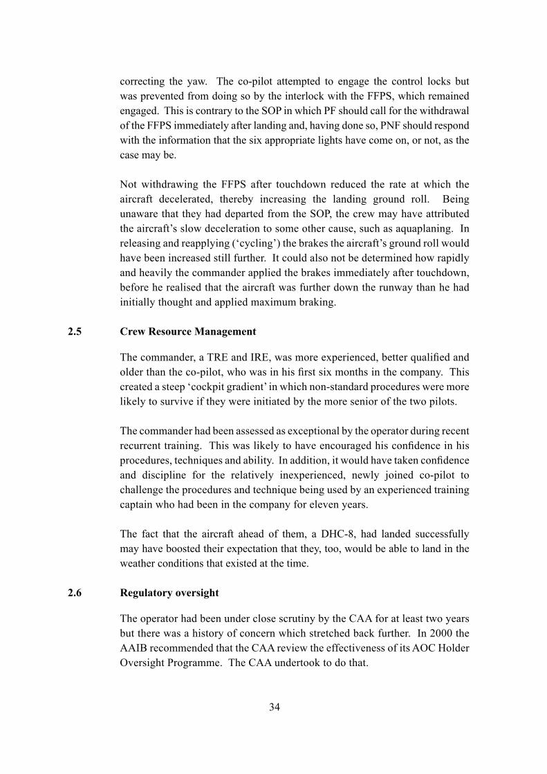
correcting the yaw. The co-pilot attempted to engage the control locks but was prevented from doing so by the interlock with the FFPS, which remained engaged. This is contrary to the SOP in which PF should call for the withdrawal of the FFPS immediately after landing and, having done so, PNF should respond with the information that the six appropriate lights have come on, or not, as the case may be.
Not withdrawing the FFPS after touchdown reduced the rate at which the aircraft decelerated, thereby increasing the landing ground roll. Being unaware that they had departed from the SOP, the crew may have attributed the aircraft’s slow deceleration to some other cause, such as aquaplaning. In releasing and reapplying (‘cycling’) the brakes the aircraft’s ground roll would have been increased still further. It could also not be determined how rapidly and heavily the commander applied the brakes immediately after touchdown, before he realised that the aircraft was further down the runway than he had initially thought and applied maximum braking.
2.5 Crew Resource Management
The commander, a TRE and IRE, was more experienced, better qualified and older than the co-pilot, who was in his first six months in the company. This created a steep ‘cockpit gradient’ in which non-standard procedures were more likely to survive if they were initiated by the more senior of the two pilots.
The commander had been assessed as exceptional by the operator during recent recurrent training. This was likely to have encouraged his confidence in his procedures, techniques and ability. In addition, it would have taken confidence and discipline for the relatively inexperienced, newly joined co-pilot to challenge the procedures and technique being used by an experienced training captain who had been in the company for eleven years.
The fact that the aircraft ahead of them, a DHC-8, had landed successfully may have boosted their expectation that they, too, would be able to land in the weather conditions that existed at the time.
2.6 Regulatory oversight
The operator had been under close scrutiny by the CAA for at least two years but there was a history of concern which stretched back further. In 2000 the AAIB recommended that the CAA review the effectiveness of its AOC Holder Oversight Programme. The CAA undertook to do that.
35
Over recent years the CAA had clearly expended much time and effort in providing guidance and advice to enable the operator to achieve an acceptable standard. There was a consistent thread of close supervision and concerns about the operator’s management structure and competencies. Also, concerns were raised in audit reports and correspondence between the CAA and the operator about the operator’s training system, including CRM training, failure to remedy non-conformances within the appropriate timescale and the operator’s ability to maintain standards of safety. This serious incident, to G-BVOV, reflects some of those findings and concerns. It also echoes a previous AAIB report on a serious incident in 2005, involving one of the operator’s aircraft, in which the flight crew did not comply with SOPs.
The CAA audit, which was carried out on the operator’s training department in late March 2006, highlighted that:
‘there was no oversight of the standards of the training and checking by the operator, as evidenced by the TRE’s lack of knowledge of SOPs.’
This prompts the question as to how that could happen in an organisation that had come to the CAA’s attention over a number of years and was being closely monitored.
It is clear that much was done by the CAA, over a sustained period, to enable the operator to achieve an acceptable standard of safety. However, there was also evidence that the operator was not narrowing the gap between its performance and the required standard. In the seven months leading up to the incident, the CAA gave the operator increasingly clear objectives and timescales to meet. The evidence indicates that the circumstances surrounding this incident were a symptom of a pattern more widespread within the company, rather than being specific to this crew. Although the CAA audits had identified safety-related shortcomings to the operator, the situation did not seem to improve and this appears due, in part, to the lack of a robust, consistent and timely framework of progressive limitations on an AOC holder failing to meet the required standard.
36
Consequently, the following Safety Recommendation is made:
It is recommended that the Civil Aviation Authority implement a more robust process of graduated measures for addressing identified safety-related shortcomings in an AOC Holder’s operations, within an appropriate timescale, to ensure that the AOC Holder meets and maintains the required standard. (Safety Recommendation 2008-026)
37
3 Conclusions
(a) Findings
1. The flight crew were properly licensed and qualified to conduct the flight.
2. The flight crew were suitably rested and held valid medical certificates.
3. The aircraft was calculated to be 2,945 kg below the maximum authorised landing weight for Runway 27 and was loaded correctly.
4. The Landing Distance Required of 1,052 metres was within the Landing Distance Available of 1,453 metres.
5. The surface wind and visibility conditions were suitable for the aircraft to make an approach to land.
6. The commander, a Type Rating Examiner and Instrument Rating Examiner on the HS 748, did not brief the Standard Operating Procedure ‘challenge and response’ crew calls for a Category I ILS during his approach brief to the co-pilot.
7. The flight crew did not comply with the Standard Operating Procedures for a Category I ILS approach.
8. The co-pilot did not challenge the use of non-standard operating procedures.
9. The decision to land or go around was delayed significantly beyond the intersection of the Decision Altitude and the ILS glideslope.
10. The aircraft’s rate of descent was arrested, or it may have ballooned, while manoeuvring to land.
11. The aircraft landed significantly beyond the touchdown zone.
12. Friction testing of the runway showed that the runway surface condition was not a factor in the aircraft over-running the runway.
38
13. Contrary to the Standard Operating Procedures, the flight fine pitch stops were not withdrawn after landing, thereby preventing the propeller blades from moving to the ground fine pitch stops, and reducing the braking effect of the propellers.
14. The commander was not aware that the flight fine pitch stops had not been withdrawn.
15. The aircraft’s wheel braking and propeller pitch control systems were functioning correctly at the time of the incident.
16. The aircraft required at least 400 metres of runway within which to stop with maximum braking and flight fine pitch selected on both propellers.
17. Although the touchdown on Runway 27 was made with 400 to 550 metres
of runway remaining, the aircraft did not stop and overran the runway by 145 metres onto wet grass.
18. The commander did not immediately appreciate how far down the runway he had landed and delayed applying maximum braking until he saw the end of the runway.
19. The commander cycled the brakes when he realised that the aircraft was not decelerating as fast as he expected it to.
20. The No 4 tyre probably aquaplaned for a short distance on the concrete surface at the Runway 09 threshold.
21. The operator had a history of non-conformities being raised during CAA audits and had been closely monitored for at least two years. Concerns included the operator’s management structure and competencies, and its ability to maintain standards of safety.
22. A CAA audit of the operator’s flight crew training, across all their fleets, revealed that the Type Rating Examiners lacked knowledge of the operator’s Standard Operating Procedures.
39
(b) Causal factors
The investigation identified the following causal factors:
(i) The flight crew did not comply with the Standard Operating Procedures for a Category I ILS.
(ii) The commander’s decision to land or go around was delayed significantly beyond the intersection of the Decision Altitude and the ILS glideslope.
(iii) After landing, the crew did not immediately apply maximum braking or withdraw the flight fine pitch stops, as advised in the Operations Manual.
(iv) The operator’s training staff lacked knowledge of the Standard Operating Procedures.
(c) Contributory factors
(i) Close monitoring by the CAA had not revealed the depth of the lack of knowledge of Standard Operating Procedures within the operator’s flight operations department until after this incident.
40
4 Safety Recommendation
4.1 Safety Recommendation 2008-026: It is recommended that the Civil Aviation Authority implement a more robust process of graduated measures for addressing identified safety-related shortcomings in an AOC Holder’s operations, within an appropriate timescale, to ensure that the AOC Holder meets and maintains the required standard.
R D G CarterInspector of Air AccidentsAir Accidents Investigation BranchDepartment for TransportJune 2008