RadioTest Report No: EDCS - 1550042 Page No: 1 of 78 This document is uncontrolled. Please refer to the electronic copy within EDCS for the most up to date version. Cisco Systems, Inc. Company Confidential Test Report AIR-AP3802I-B-K9 AIR-AP3802I-UXK9 AIR-AP2802I-B-K9 AIR-AP2802I-UXK9 Cisco Aironet 802.11ac Dual Band Access Points FCC ID: LDK102100 5150-5250 MHz Against the following Specifications: CFR47 Part 15.407 Cisco Systems 170 West Tasman Drive San Jose, CA 95134 Author: Jose Aguirre Tested By Approved By: Jim Nicholson Title: Technical Leader, Engineering Revision: 3 This report replaces any previously entered test report under EDCS – 1550042.This test report has been electronically authorized and archived using the CISCO Engineering Document Control system.
Transcript
RadioTest Report No: EDCS - 1550042
Page No: 1 of 78
This document is uncontrolled. Please refer to the electronic copy within EDCS for the most up to date version. Cisco Systems, Inc. Company Confidential
This report replaces any previously entered test report under EDCS – 1550042.This test report has been electronically
authorized and archived using the CISCO Engineering Document Control system.
RadioTest Report No: EDCS - 1550042
Page No: 2 of 78
This document is uncontrolled. Please refer to the electronic copy within EDCS for the most up to date version. Cisco Systems, Inc. Company Confidential
This test report has been electronically authorized and archived using the CISCO Engineering Document Control system.
SECTION 2: ASSESSMENT INFORMATION ....................................................................................................... 4
2.1 GENERAL ............................................................................................................................................................. 4
2.2 DATE OF TESTING................................................................................................................................................. 6
2.3 REPORT ISSUE DATE ............................................................................................................................................ 6
B.2 RADIATED EMISSIONS 30MHZ TO 1GHZ .................................................................................................. 66
B.3 AC CONDUCTED EMISSIONS ..................................................................................................................... 68
PHOTOGRAPHS OF SETUP .................................................................................................................................. 71
APPENDIX C: LIST OF TEST EQUIPMENT USED TO PERFORM THE TEST .................................... 75
APPENDIX E: ABBREVIATION KEY AND DEFINITIONS ...................................................................... 77
RadioTest Report No: EDCS - 1550042
Page No: 3 of 78
This document is uncontrolled. Please refer to the electronic copy within EDCS for the most up to date version. Cisco Systems, Inc. Company Confidential
Section 1: Overview
The samples were assessed against the tests detailed in section 3 under the requirements of the following
specifications:
Specifications:
CFR47 Part 15.407
Measurements were made in accordance with
ANSI C63.10:2013 KDB 789033 D02 General UNII Test Procedures New Rules v01r01 KDB 662911 D01 Multiple Transmitter Output v02r01
RadioTest Report No: EDCS - 1550042
Page No: 4 of 78
This document is uncontrolled. Please refer to the electronic copy within EDCS for the most up to date version. Cisco Systems, Inc. Company Confidential
Section 2: Assessment Information
2.1 General
This report contains an assessment of an apparatus against Electromagnetic Compatibility Standards based upon tests
carried out on the samples submitted. The testing was performed by and for the use of Cisco systems Inc:
With regard to this assessment, the following points should be noted:
a) The results contained in this report relate only to the items tested and were obtained in the period between the
date of the initial assessment and the date of issue of the report. Manufactured products will not necessarily
give identical results due to production and measurement tolerances.
b) The apparatus was set up and exercised using the configuration and modes of operation defined in this report
only.
c) Where relevant, the apparatus was only assessed using the susceptibility criteria defined in this report and the
Test Assessment Plan (TAP).
d) All testing was performed under the following environmental conditions:
Temperature 15°C to 35°C (54°F to 95°F)
Atmospheric Pressure 860mbar to 1060mbar (25.4" to 31.3")
Humidity 10% to 75*%
e) All AC testing was performed at one or more of the following supply voltages:
110V 60 Hz (+/-20%)
Units of Measurement
The units of measurements defined in the appendices are reported in specific terms, which are test dependent. Where
radiated measurements are concerned these are defined at a particular distance. Basic voltage measurements are
defined in units of [dBuV]
As an example, the basic calculation for all measurements is as follows:
Emission level [dBuV] = Indicated voltage level [dBuV] + Cable Loss [dB] + Other correction factors [dB]
The combinations of correction factors are dependent upon the exact test configurations [see test equipment lists for
further details] and may include:-
Antenna Factors, Pre Amplifier Gain, LISN Loss, Pulse Limiter Loss and Filter Insertion Loss..
Note: to convert the results from dBuV/m to uV/m use the following formula:-
Level in uV/m = Common Antilogarithm [(X dBuV/m)/20] = Y uV/m
RadioTest Report No: EDCS - 1550042
Page No: 5 of 78
This document is uncontrolled. Please refer to the electronic copy within EDCS for the most up to date version. Cisco Systems, Inc. Company Confidential
Measurement Uncertainty Values
voltage and power measurements ± 2 dB
conducted EIRP measurements ± 1.4 dB
radiated measurements ± 3.2 dB
frequency measurements ± 2.4 10-7
temperature measurements ± 0.54º
humidity measurements ± 2.3%
DC and low frequency measurements ± 2.5%
Where relevant measurement uncertainty levels have been estimated for tests performed on the apparatus. This uncertainty represents an expanded uncertainty expressed at approximately the 95% confidence level using a coverage factor of k=2.
30 MHz - 300 MHz +/- 3.8 dB 300 MHz - 1000 MHz +/- 4.3 dB 1 GHz - 10 GHz +/- 4.0 dB 10 GHz - 18GHz +/- 8.2 dB 18GHz - 26.5GHz +/- 4.1 dB 26.5GHz - 40GHz +/- 3.9 dB
Conducted emissions (expanded uncertainty, confidence interval 95%) 30 MHz – 40GHz +/- 0.38 dB A product is considered to comply with a requirement if the nominal measured value is below the limit line. The product is considered to not be in compliance in case the nominal measured value is above the limit line.
This report must not be reproduced except in full, without written approval of Cisco Systems.
RadioTest Report No: EDCS - 1550042
Page No: 6 of 78
This document is uncontrolled. Please refer to the electronic copy within EDCS for the most up to date version. Cisco Systems, Inc. Company Confidential
2.2 Date of testing
14-Jan-2016 – 22-February-2016
2.3 Report Issue Date
22-Feb-2016
Cisco uses an electronic system to issue, store and control the revision of test reports. This system is called the Engineering Document Control System (EDCS). The actual report issue date is embedded into the original file on EDCS. Any copies of this report, either electronic or paper, that are not on EDCS must be considered uncontrolled.
2.4 Testing facilities
This assessment was performed by:
Testing Laboratory
Cisco Systems, Inc.,
125 West Tasman Drive
San Jose, CA 95134, USA
Registration Numbers for Industry Canada
Cisco System Site Address Site Identifier
Building P, 10m Chamber 125 West Tasman Dr San Jose, CA 95134
Company #: 2461N-2
Building P, 5m Chamber 125 West Tasman Dr San Jose, CA 95134
Company #: 2461N-1
Building I, 5m Chamber 285 W. Tasman Drive San Jose, California 95134
Company #: 2461M-1
Test Engineers
Jose Aguirre
2.5 Equipment Assessed (EUT)
AIR-AP3802I-B-K9
RadioTest Report No: EDCS - 1550042
Page No: 7 of 78
This document is uncontrolled. Please refer to the electronic copy within EDCS for the most up to date version. Cisco Systems, Inc. Company Confidential
2.6 EUT Description The Cisco Aironet 802.11ac Radio supports the following modes of operation. The modes are further defined in the radio Theory of Operation. The modes included in this report represent the worst case data for all modes.
802.11n/ac - Non HT/VHT20, One Antenna, 6 to 54 Mbps 802.11n/ac - Non HT/VHT20, Two Antennas, 6 to 54 Mbps 802.11n/ac - Non HT/VHT20, Three Antennas, 6 to 54 Mbps 802.11n/ac - Non HT/VHT20, Four Antennas, 6 to 54 Mbps 802.11n/ac - Non HT/VHT20 Beam Forming, Two Antennas, 6 to 54 Mbps 802.11n/ac - Non HT/VHT20 Beam Forming, Three Antennas, 6 to 54 Mbps 802.11n/ac - Non HT/VHT20 Beam Forming, Four Antennas, 6 to 54 Mbps 802.11n/ac - HT/VHT20, One Antenna, M0 to M7 802.11n/ac - HT/VHT20, Two Antennas, M0 to M7 802.11n/ac - HT/VHT20, Two Antennas, M8 to M15 802.11n/ac - HT/VHT20, Three Antennas, M0 to M7 802.11n/ac - HT/VHT20, Three Antennas, M8 to M15 802.11n/ac - HT/VHT20, Three Antennas, M16 to M23 802.11n/ac - HT/VHT20, Four Antennas, M0 to M7 802.11n/ac - HT/VHT20, Four Antennas, M8 to M15 802.11n/ac - HT/VHT20, Four Antennas, M16 to M23 802.11n/ac - HT/VHT20 Beam Forming, Two Antennas, M0 to M7 802.11n/ac - HT/VHT20 Beam Forming, Two Antennas, M8 to M15 802.11n/ac - HT/VHT20 Beam Forming, Three Antennas, M0 to M7 802.11n/ac - HT/VHT20 Beam Forming, Three Antennas, M8 to M15 802.11n/ac - HT/VHT20 Beam Forming, Three Antennas, M16 to M23 802.11n/ac - HT/VHT20 Beam Forming, Four Antennas, M0 to M7 802.11n/ac - HT/VHT20 Beam Forming, Four Antennas, M8 to M15 802.11n/ac - HT/VHT20 Beam Forming, Four Antennas, M16 to M23 802.11n/ac - HT/VHT20 STBC, Two Antennas, M0 to M7 802.11n/ac - HT/VHT20 STBC, Three Antennas, M0 to M7 802.11n/ac - HT/VHT20 STBC, Four Antennas, M0 to M7 802.11n/ac - Non HT/VHT40 Duplicate, One Antenna, 6 to 54 Mbps 802.11n/ac - Non HT/VHT40 Duplicate, Two Antennas, 6 to 54 Mbps 802.11n/ac - Non HT/VHT40 Duplicate, Three Antennas, 6 to 54 Mbps 802.11n/ac - Non HT/VHT40 Duplicate, Four Antennas, 6 to 54 Mbps 802.11n/ac - HT/VHT40, One Antenna, M0 to M7 802.11n/ac - HT/VHT40, Two Antennas, M0 to M7 802.11n/ac - HT/VHT40, Two Antennas, M8 to M15 802.11n/ac - HT/VHT40, Three Antennas, M0 to M7 802.11n/ac - HT/VHT40, Three Antennas, M8 to M15 802.11n/ac - HT/VHT40, Three Antennas, M16 to M23 802.11n/ac - HT/VHT40, Four Antennas, M0 to M7 802.11n/ac - HT/VHT40, Four Antennas, M8 to M15 802.11n/ac - HT/VHT40, Four Antennas, M16 to M23 802.11n/ac - HT/VHT40 Beam Forming, Two Antennas, M0 to M7 802.11n/ac - HT/VHT40 Beam Forming, Two Antennas, M8 to M15 802.11n/ac - HT/VHT40 Beam Forming, Three Antennas, M0 to M7 802.11n/ac - HT/VHT40 Beam Forming, Three Antennas, M8 to M15 802.11n/ac - HT/VHT40 Beam Forming, Three Antennas, M16 to M23 802.11n/ac - HT/VHT40 Beam Forming, Four Antennas, M0 to M7 802.11n/ac - HT/VHT40 Beam Forming, Four Antennas, M8 to M15 802.11n/ac - HT/VHT40 Beam Forming, Four Antennas, M16 to M23
RadioTest Report No: EDCS - 1550042
Page No: 8 of 78
This document is uncontrolled. Please refer to the electronic copy within EDCS for the most up to date version. Cisco Systems, Inc. Company Confidential
802.11n/ac - HT/VHT40 STBC, Two Antennas, M0 to M7 802.11n/ac - HT/VHT40 STBC, Three Antennas, M0 to M7 802.11n/ac - HT/VHT40 STBC, Four Antennas, M0 to M7 802.11n/ac - Non HT/VHT80 Duplicate, One Antenna, 6 to 54 Mbps 802.11n/ac - Non HT/VHT80 Duplicate, Two Antennas, 6 to 54 Mbps 802.11n/ac - Non HT/VHT80 Duplicate, Three Antennas, 6 to 54 Mbps 802.11n/ac - Non HT/VHT80 Duplicate, Four Antennas, 6 to 54 Mbps 802.11n/ac - HT/VHT80, One Antenna, M0 to M7 802.11n/ac - HT/VHT80, Two Antennas, M0 to M7 802.11n/ac - HT/VHT80, Two Antennas, M8 to M15 802.11n/ac - HT/VHT80, Three Antennas, M0 to M7 802.11n/ac - HT/VHT80, Three Antennas, M8 to M15 802.11n/ac - HT/VHT80, Three Antennas, M16 to M23 802.11n/ac - HT/VHT80, Four Antennas, M0 to M7 802.11n/ac - HT/VHT80, Four Antennas, M8 to M15 802.11n/ac - HT/VHT80, Four Antennas, M16 to M23 802.11n/ac - HT/VHT80 Beam Forming, Two Antennas, M0 to M7 802.11n/ac - HT/VHT80 Beam Forming, Two Antennas, M8 to M15 802.11n/ac - HT/VHT80 Beam Forming, Three Antennas, M0 to M7 802.11n/ac - HT/VHT80 Beam Forming, Three Antennas, M8 to M15 802.11n/ac - HT/VHT80 Beam Forming, Three Antennas, M16 to M23 802.11n/ac - HT/VHT80 Beam Forming, Four Antennas, M0 to M7 802.11n/ac - HT/VHT80 Beam Forming, Four Antennas, M8 to M15 802.11n/ac - HT/VHT80 Beam Forming, Four Antennas, M16 to M23 802.11n/ac - HT/VHT80 STBC, Two Antennas, M0 to M7 802.11n/ac - HT/VHT80 STBC, Three Antennas, M0 to M7 802.11n/ac - HT/VHT80 STBC, Four Antennas, M0 to M7
The following antennas are supported by this product series. The data included in this report represent the worst case data for all antennas.
Frequency Part Number Antenna Type
Antenna Gain (dBi)
5 GHz 2.4 / 5 GHz
Internal Directional (5G XOR) 6
Internal Omni (2.4G XOR / 5G Dedicated) 4 / 5
RadioTest Report No: EDCS - 1550042
Page No: 9 of 78
This document is uncontrolled. Please refer to the electronic copy within EDCS for the most up to date version. Cisco Systems, Inc. Company Confidential
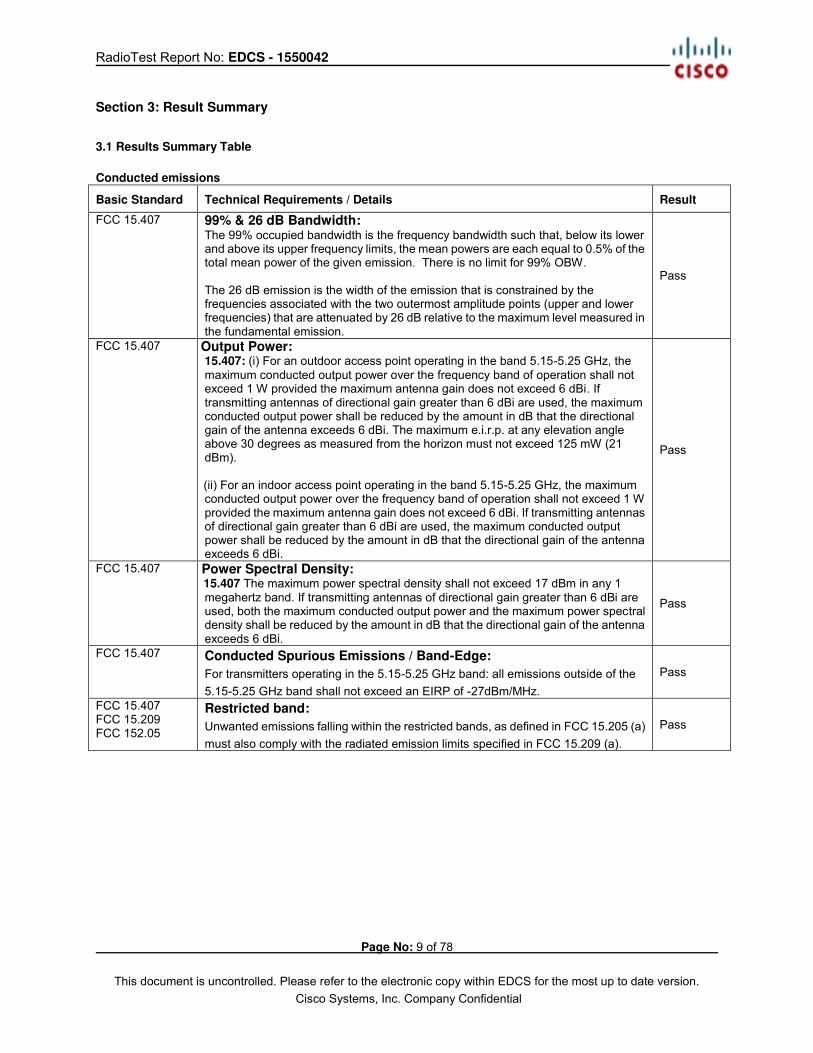
Section 3: Result Summary
3.1 Results Summary Table Conducted emissions
Basic Standard Technical Requirements / Details Result
FCC 15.407 99% & 26 dB Bandwidth: The 99% occupied bandwidth is the frequency bandwidth such that, below its lower and above its upper frequency limits, the mean powers are each equal to 0.5% of the total mean power of the given emission. There is no limit for 99% OBW. The 26 dB emission is the width of the emission that is constrained by the frequencies associated with the two outermost amplitude points (upper and lower frequencies) that are attenuated by 26 dB relative to the maximum level measured in the fundamental emission.
Pass
FCC 15.407 Output Power: 15.407: (i) For an outdoor access point operating in the band 5.15-5.25 GHz, the maximum conducted output power over the frequency band of operation shall not exceed 1 W provided the maximum antenna gain does not exceed 6 dBi. If transmitting antennas of directional gain greater than 6 dBi are used, the maximum conducted output power shall be reduced by the amount in dB that the directional gain of the antenna exceeds 6 dBi. The maximum e.i.r.p. at any elevation angle above 30 degrees as measured from the horizon must not exceed 125 mW (21 dBm). (ii) For an indoor access point operating in the band 5.15-5.25 GHz, the maximum conducted output power over the frequency band of operation shall not exceed 1 W provided the maximum antenna gain does not exceed 6 dBi. If transmitting antennas of directional gain greater than 6 dBi are used, the maximum conducted output power shall be reduced by the amount in dB that the directional gain of the antenna exceeds 6 dBi.
Pass
FCC 15.407 Power Spectral Density: 15.407 The maximum power spectral density shall not exceed 17 dBm in any 1 megahertz band. If transmitting antennas of directional gain greater than 6 dBi are used, both the maximum conducted output power and the maximum power spectral density shall be reduced by the amount in dB that the directional gain of the antenna exceeds 6 dBi.
Pass
FCC 15.407 Conducted Spurious Emissions / Band-Edge: For transmitters operating in the 5.15-5.25 GHz band: all emissions outside of the 5.15-5.25 GHz band shall not exceed an EIRP of -27dBm/MHz.
Pass
FCC 15.407 FCC 15.209 FCC 152.05
Restricted band:
Unwanted emissions falling within the restricted bands, as defined in FCC 15.205 (a) must also comply with the radiated emission limits specified in FCC 15.209 (a).
Pass
RadioTest Report No: EDCS - 1550042
Page No: 10 of 78
This document is uncontrolled. Please refer to the electronic copy within EDCS for the most up to date version. Cisco Systems, Inc. Company Confidential
Radiated Emissions (General requirements)
Basic Standard Technical Requirements / Details Result
FCC 15.209 FCC 15.205
TX Spurious Emissions: Except as provided elsewhere in this subpart, the emissions from an intentional radiator shall not exceed the field strength levels specified in the filed strength limits table in this section.
Pass
FCC 15.207 AC conducted Emissions: Except when the requirements applicable to a given device state otherwise, for any radio apparatus equipped to operate from the public utility AC power supply, either directly or indirectly (such as with a battery charger), the radio frequency voltage of emissions conducted back onto the AC power lines in the frequency range of 0.15 MHz to 30 MHz shall not exceed the limits shown in the table in these sections. The more stringent limit applies at the frequency range boundaries.
Pass
* MPE calculation is recorded in a separate report
RadioTest Report No: EDCS - 1550042
Page No: 11 of 78
This document is uncontrolled. Please refer to the electronic copy within EDCS for the most up to date version. Cisco Systems, Inc. Company Confidential
Section 4: Sample Details
Note: Each sample was evaluated to ensure that its condition was suitable to be used as a test sample prior to the commencement of testing. 4.1 Sample Details
Sample
No. Equipment Details Manufacturer Hardware Rev.
Firmware Rev.
Software Rev.
Serial Number
S01 AIR-AP3802I-B-K9 Cisco Systems V00 8.3.1.51 8.3.1.51 FOC19448XL0E
S02* PWR-CUBE-B Delta 341-100460-001 NA NA Engineering
Sample (*) S02 are support equipment Power supplies for EUT S01 4.2 System Details
ANSI C63.10:2013 KDB 789033 D02 General UNII Test Procedures New Rules v01r01 KDB 662911 D01 Multiple Transmitter Output v02r01
RadioTest Report No: EDCS - 1550042
Page No: 12 of 78
This document is uncontrolled. Please refer to the electronic copy within EDCS for the most up to date version. Cisco Systems, Inc. Company Confidential
Appendix A: Emission Test Results
Conducted Test Setup Diagram
Target Maximum Channel Power The following table details the maximum supported Total Channel Power for all operating modes.
Maximum Channel
Power (dBm)
Operating Mode
Frequency (MHz)
5180 5220
Non HT20, 6 to 54 Mbps 22 23
Non HT20 Beam Forming, 6 to 54 Mbps 20 23
HT/VHT20, M0 to M23, M0 to M9 1-0ss 23 24
HT/VHT20 Beam Forming, M0 to M23, M0 to M9 1-0ss 22 24
HT/VHT20 STBC, M0 to M7 23 24
5190 5230
Non HT40, 6 to 54 Mbps 21 25
HT/VHT40, M0 to M23, M0 to M9 1-0ss 22 24
HT/VHT40 Beam Forming, M0 to M23, M0 to M9 1-0ss 21 24
HT/VHT40 STBC, M0 to M7 22 24
5210
Non HT80, 6 to 54 Mbps 19
VHT80, M0 to M9, M0 to M9 1-0ss 21
VHT80 Beam Forming, M0 to M9, M0 to M9 1-0ss 21
VHT80 STBC, M0.1 to M9.1 21
DUT
4-way
Splitter
Combiner
RF
Switch
2.4G-2.5G
Notch Filter
5.15G-5.35G
Notch Filter
5.47G-5.725G
Notch Filter
5.725G-5.875G
Notch Filter
Pass through cable
RF
Switch
2-way
Splitter
Combiner
Spectrum
Analyzer
Signal
Generator Circulator
RadioTest Report No: EDCS - 1550042
Page No: 13 of 78
This document is uncontrolled. Please refer to the electronic copy within EDCS for the most up to date version. Cisco Systems, Inc. Company Confidential
A.1 99% and 26dB Bandwidth FCC 15.407 The 99% occupied bandwidth is the frequency bandwidth such that, below its lower and above its upper frequency limits, the mean powers are each equal to 0.5% of the total mean power of the given emission. There is no limit for 99% OBW. The 26 dB emission is the width of the emission that is constrained by the frequencies associated with the two outermost amplitude points (upper and lower frequencies) that are attenuated by 26 dB relative to the maximum level measured in the fundamental emission.
Test Procedure Ref. ANSI C63.10: 2013 Section 6.9.3 99% BW and EBW (-26dB)
Test Procedure 1. Set the radio in the continuous transmitting mode. 2. Allow the trace to stabilize. 3. Setting the x-dB bandwidth mode to -26dB and OBW power function to 99% within the measurement set up function. 4. Select the automatic OBW measurement function of an instrument to perform bandwidth measurement. 5. Capture graphs and record pertinent measurement data. Ref. ANSI C63.10: 2013 Section 6.9.3 99% BW and EBW (-26dB)
Test parameters Span = 1.5 x to 5.0 times OBW RBW = approx. 1% to 5% of the OBW VBW ≥ 3 x RBW Detector = Peak or where practical sample shall be used Trace = Max. Hold System
Number Description Samples
System under
test
Support
equipment
1 EUT S01 Support S02
Tested By :
Jose Aguirre Date of testing:
14-Jan-2016 – 22-February-2016 Test Result : PASS
See Appendix C for list of test equipment
RadioTest Report No: EDCS - 1550042
Page No: 14 of 78
This document is uncontrolled. Please refer to the electronic copy within EDCS for the most up to date version. Cisco Systems, Inc. Company Confidential
Frequency
(MHz) Mode
Data Rate
(Mbps)
26dB BW
(MHz)
99% BW
(MHz)
5180 Non HT/VHT20, 6 to 54 Mbps 6 23.1 18.0
HT/VHT20, M0 to M23, M0 to M9 1-0ss m0 27.1 18.3
5190 Non HT/VHT40, 6 to 54 Mbps 6 46.7 37.0
HT/VHT40, M0 to M23, M0 to M9 1-0ss m0 44.9 36.7
5210 Non HT/VHT80, 6 to 54 Mbps 6 82.4 76.2
HT/VHT80, M0 to M23, M0 to M9 1-0ss m0x1 82.1 76.5
5220 Non HT/VHT20, 6 to 54 Mbps 6 22.5 18.0
HT/VHT20, M0 to M23, M0 to M9 1-0ss m0 23.8 18.3
5230 Non HT/VHT40, 6 to 54 Mbps 6 46.9 36.9
HT/VHT40, M0 to M23, M0 to M9 1-0ss m0 43.8 36.6
5240 Non HT/VHT20, 6 to 54 Mbps 6 22.9 18.0
HT/VHT20, M0 to M23, M0 to M9 1-0ss m0 22.9 18.3
RadioTest Report No: EDCS - 1550042
Page No: 15 of 78
This document is uncontrolled. Please refer to the electronic copy within EDCS for the most up to date version. Cisco Systems, Inc. Company Confidential
26dB / 99% Bandwidth, 5180 MHz, Non HT/VHT20, 6 to 54 Mbps
26dB / 99% Bandwidth, 5180 MHz, HT/VHT20, M0 to M23, M0 to M9 1-0ss
RadioTest Report No: EDCS - 1550042
Page No: 16 of 78
This document is uncontrolled. Please refer to the electronic copy within EDCS for the most up to date version. Cisco Systems, Inc. Company Confidential
26dB / 99% Bandwidth, 5190 MHz, Non HT/VHT40, 6 to 54 Mbps
26dB / 99% Bandwidth, 5190 MHz, HT/VHT40, M0 to M23, M0 to M9 1-0ss
RadioTest Report No: EDCS - 1550042
Page No: 17 of 78
This document is uncontrolled. Please refer to the electronic copy within EDCS for the most up to date version. Cisco Systems, Inc. Company Confidential
26dB / 99% Bandwidth, 5210 MHz, Non HT/VHT80, 6 to 54 Mbps
26dB / 99% Bandwidth, 5210 MHz, HT/VHT80, M0 to M23, M0 to M9 1-0ss
RadioTest Report No: EDCS - 1550042
Page No: 18 of 78
This document is uncontrolled. Please refer to the electronic copy within EDCS for the most up to date version. Cisco Systems, Inc. Company Confidential
26dB / 99% Bandwidth, 5220 MHz, Non HT/VHT20, 6 to 54 Mbps
26dB / 99% Bandwidth, 5220 MHz, HT/VHT20, M0 to M23, M0 to M9 1-0ss
RadioTest Report No: EDCS - 1550042
Page No: 19 of 78
This document is uncontrolled. Please refer to the electronic copy within EDCS for the most up to date version. Cisco Systems, Inc. Company Confidential
26dB / 99% Bandwidth, 5230 MHz, Non HT/VHT40, 6 to 54 Mbps
26dB / 99% Bandwidth, 5230 MHz, HT/VHT40, M0 to M23, M0 to M9 1-0ss
RadioTest Report No: EDCS - 1550042
Page No: 20 of 78
This document is uncontrolled. Please refer to the electronic copy within EDCS for the most up to date version. Cisco Systems, Inc. Company Confidential
26dB / 99% Bandwidth, 5240 MHz, Non HT/VHT20, 6 to 54 Mbps
26dB / 99% Bandwidth, 5240 MHz, HT/VHT20, M0 to M23, M0 to M9 1-0ss
RadioTest Report No: EDCS - 1550042
Page No: 21 of 78
This document is uncontrolled. Please refer to the electronic copy within EDCS for the most up to date version. Cisco Systems, Inc. Company Confidential
A.2 Maximum Conducted Output Power/ Power Spectral Density 15.407 (i) For an outdoor access point operating in the band 5.15-5.25 GHz, the maximum conducted output power over the frequency band of operation shall not exceed 1 W provided the maximum antenna gain does not exceed 6 dBi. In addition, the maximum power spectral density shall not exceed 17 dBm in any 1 megahertz band. If transmitting antennas of directional gain greater than 6 dBi are used, both the maximum conducted output power and the maximum power spectral density shall be reduced by the amount in dB that the directional gain of the antenna exceeds 6 dBi. The maximum e.i.r.p. at any elevation angle above 30 degrees as measured from the horizon must not exceed 125 mW (21 dBm). (ii) For an indoor access point operating in the band 5.15-5.25 GHz, the maximum conducted output power over the frequency band of operation shall not exceed 1 W provided the maximum antenna gain does not exceed 6 dBi. In addition, the maximum power spectral density shall not exceed 17 dBm in any 1 megahertz band. If transmitting antennas of directional gain greater than 6 dBi are used, both the maximum conducted output power and the maximum power spectral density shall be reduced by the amount in dB that the directional gain of the antenna exceeds 6 dBi.
Test Procedure Ref. KDB 789033 D02 General UNII Test Procedures New Rules v01r01
ANSI C63.10: 2013 Output Power
Test Procedure 1. Set the radio in the continuous transmitting mode at full power 2. Compute power by integrating the spectrum across the EBW (or alternatively entire 99% OBW) of the signal using the instrument’s band power measurement function. The integration shall be performed using the spectrum analyzer band-power measurement function with band limits set equal to the EBW or the OBW band edges. 3. Capture graphs and record pertinent measurement data. Ref. KDB 789033 D02 General UNII Test Procedures New Rules v01r01
ANSI C63.10: 2013 section 12.3.2.2 Method SA-1 Output Power
Test parameters Span = >1.5 times the OBW RBW = 1MHz VBW ≥ 3 x RBW Sweep = Auto couple Detector = sample Trace = Trace Average 100 The “measure-and-sum technique” is used for measuring in-band transmit power of a device. In the measure-and-sum approach, the conducted emission level is measured at each antenna port. The measured results at the various antenna ports are then summed mathematically to determine the total emission level from the device. Summing is performed in linear power units. (See ANSI C63.10 section 14.3.2.2) System
Number Description Samples
System under
test
Support
equipment
1 EUT S01 Support S02
RadioTest Report No: EDCS - 1550042
Page No: 22 of 78
This document is uncontrolled. Please refer to the electronic copy within EDCS for the most up to date version. Cisco Systems, Inc. Company Confidential
Tested By :
Jose Aguirre Date of testing:
14-Jan-2016 – 22-February-201 Test Result : PASS
See Appendix C for list of test equipment
RadioTest Report No: EDCS - 1550042
Page No: 23 of 78
This document is uncontrolled. Please refer to the electronic copy within EDCS for the most up to date version. Cisco Systems, Inc. Company Confidential
Fre
qu
en
cy
(M
Hz)
Mode Tx
Path
s
Co
rrela
ted
An
ten
na
Gain
(d
Bi)
Tx
1 M
ax P
ow
er
(dB
m)
Tx
2 M
ax P
ow
er
(dB
m)
Tx
3 M
ax P
ow
er
(dB
m)
Tx
4 M
ax P
ow
er
(dB
m)
To
tal
Tx C
ha
nn
el
Po
wer
(dB
m)
Lim
it (
dB
m)
EIR
P
Ma
rgin
(d
B)
51
80
Non HT20, 6 to 54 Mbps 1 5 16.3 16.3 30.0 13.7
Non HT20, 6 to 54 Mbps 2 5 16.3 17.4 19.9 30.0 10.1
Non HT20, 6 to 54 Mbps 3 5 16.3 17.4 17.7 21.9 30.0 8.1
Non HT20, 6 to 54 Mbps 4 5 15.1 16.2 16.6 15.2 21.8 30.0 8.2
Non HT20 Beam Forming, 6 to 54 Mbps 2 8 16.3 17.4 19.9 28.0 8.1
Non HT20 Beam Forming, 6 to 54 Mbps 3 10 13.8 15.0 15.5 19.6 26.0 6.4
Non HT20 Beam Forming, 6 to 54 Mbps 4 11 8.7 9.9 10.7 8.9 15.6 25.0 9.4
Non HT40, 6 to 54 Mbps 2 5 16.4 17.2 19.8 30.0 10.2
Non HT40, 6 to 54 Mbps 3 5 15.3 16.0 16.6 20.8 30.0 9.2
Non HT40, 6 to 54 Mbps 4 5 14.2 15.0 15.5 14.1 20.8 30.0 9.2
HT/VHT40, M0 to M7 1 5 16.4 16.4 30.0 13.6
HT/VHT40, M0 to M7 2 5 16.4 17.3 19.9 30.0 10.1
HT/VHT40, M8 to M15 2 5 16.4 17.3 19.9 30.0 10.1
RadioTest Report No: EDCS - 1550042
Page No: 24 of 78
This document is uncontrolled. Please refer to the electronic copy within EDCS for the most up to date version. Cisco Systems, Inc. Company Confidential
This document is uncontrolled. Please refer to the electronic copy within EDCS for the most up to date version. Cisco Systems, Inc. Company Confidential
52
20
Non HT20, 6 to 54 Mbps 1 5 17.8 17.8 30.0 12.2
Non HT20, 6 to 54 Mbps 2 5 17.8 17.3 20.6 30.0 9.4
Non HT20, 6 to 54 Mbps 3 5 17.8 17.3 18.6 22.7 30.0 7.3
Non HT20, 6 to 54 Mbps 4 5 16.5 16.1 16.4 16.0 22.3 30.0 7.7
Non HT20 Beam Forming, 6 to 54 Mbps 2 8 17.8 17.3 20.6 28.0 7.4
Non HT20 Beam Forming, 6 to 54 Mbps 3 10 17.8 17.3 18.6 22.7 26.0 3.3
Non HT20 Beam Forming, 6 to 54 Mbps 4 11 16.5 16.1 16.4 16.0 22.3 25.0 2.7
This document is uncontrolled. Please refer to the electronic copy within EDCS for the most up to date version. Cisco Systems, Inc. Company Confidential
This document is uncontrolled. Please refer to the electronic copy within EDCS for the most up to date version. Cisco Systems, Inc. Company Confidential
Fre
qu
en
cy
(M
Hz)
Mode Tx
Path
s
Co
rrela
ted
An
ten
na
Gain
(d
Bi)
Tx
1 P
SD
(d
Bm
/MH
z)
Tx
2 P
SD
(d
Bm
/MH
z)
Tx
3 P
SD
(d
Bm
/MH
z)
Tx
4 P
SD
(d
Bm
/MH
z)
To
tal P
SD
(d
Bm
/MH
z)
Lim
it (
dB
m/M
Hz)
EIR
P
Ma
rgin
(d
B)
51
80
Non HT20, 6 to 54 Mbps 1 5 5.7 5.7 17.0 11.3
Non HT20, 6 to 54 Mbps 2 8 5.7 7.2 9.5 15.0 5.5
Non HT20, 6 to 54 Mbps 3 10 5.7 7.2 7.2 11.5 13.0 1.5
Non HT20, 6 to 54 Mbps 4 11 4.7 5.8 6.2 4.5 11.4 12.0 0.6
Non HT20 Beam Forming, 6 to 54 Mbps 2 8 5.7 7.2 9.5 15.0 5.5
Non HT20 Beam Forming, 6 to 54 Mbps 3 10 3.4 4.5 4.9 9.1 13.0 3.9
Non HT20 Beam Forming, 6 to 54 Mbps 4 11 -1.9 -0.5 0.1 -1.8 5.1 12.0 6.9
Non HT40, 6 to 54 Mbps 3 10 1.9 2.5 3.1 7.3 13.0 5.7
Non HT40, 6 to 54 Mbps 4 11 1.1 1.7 2.1 0.6 7.4 12.0 4.6
HT/VHT40, M0 to M7 1 5 2.9 2.9 17.0 14.1
HT/VHT40, M0 to M7 2 8 2.9 3.6 6.3 15.0 8.7
HT/VHT40, M8 to M15 2 5 2.9 3.6 6.3 17.0 10.7
RadioTest Report No: EDCS - 1550042
Page No: 28 of 78
This document is uncontrolled. Please refer to the electronic copy within EDCS for the most up to date version. Cisco Systems, Inc. Company Confidential
This document is uncontrolled. Please refer to the electronic copy within EDCS for the most up to date version. Cisco Systems, Inc. Company Confidential
52
20
Non HT20, 6 to 54 Mbps 1 5 7.4 7.4 17.0 9.6
Non HT20, 6 to 54 Mbps 2 8 7.4 6.6 10.0 15.0 5.0
Non HT20, 6 to 54 Mbps 3 10 7.4 6.6 8.0 12.1 13.0 0.9
Non HT20, 6 to 54 Mbps 4 11 6.1 5.5 5.8 5.8 11.8 12.0 0.2
Non HT20 Beam Forming, 6 to 54 Mbps 2 8 7.4 6.6 10.0 15.0 5.0
Non HT20 Beam Forming, 6 to 54 Mbps 3 10 7.4 6.6 8.0 12.1 13.0 0.9
Non HT20 Beam Forming, 6 to 54 Mbps 4 11 6.1 5.5 5.8 5.8 11.8 12.0 0.2
This document is uncontrolled. Please refer to the electronic copy within EDCS for the most up to date version. Cisco Systems, Inc. Company Confidential
This document is uncontrolled. Please refer to the electronic copy within EDCS for the most up to date version. Cisco Systems, Inc. Company Confidential
This document is uncontrolled. Please refer to the electronic copy within EDCS for the most up to date version. Cisco Systems, Inc. Company Confidential
Power Spectral Density, 5240 MHz, HT/VHT20, M0 to M7
Antenna A Antenna B
Antenna C Antenna D
RadioTest Report No: EDCS - 1550042
Page No: 33 of 78
This document is uncontrolled. Please refer to the electronic copy within EDCS for the most up to date version. Cisco Systems, Inc. Company Confidential
A.3 Conducted Spurious Emissions 15.407 (b) Undesirable emission limits. Except as shown in paragraph (b) (7) of this section, the maximum emissions outside of the frequency bands of operation shall be attenuated in accordance with the following limits: (1) For transmitters operating in the 5.15-5.25 GHz band: All emissions outside of the 5.15-5.35 GHz band shall not exceed an e.i.r.p. of −27 dBm/MHz. Radiated emissions which fall in the restricted bands, as defined in Section 15.205(a), must also comply with the radiated emission limits specified in Section 15.209(a) (see Section 15.205(c)). Test Procedure Ref. KDB 789033 D02 General UNII Test Procedures New Rules v01r01
ANSI C63.10: 2013 Conducted Spurious Emissions
Test Procedure 1. Connect the antenna port(s) to the spectrum analyzer input. 2. Place the radio in continuous transmit mode. Use the procedures in KDB 789033 D02 General UNII Test Procedures New Rules v01 to substitute conducted measurements in place of radiated measurements. 3. Configure Spectrum analyzer as per test parameters below (be sure to enter all losses between the transmitter output and the spectrum analyzer). 4. Record the marker waveform peak to spur difference. Also measure any emissions in the restricted bands. 5. The “measure-and-sum technique” is used for measuring in-band transmit power of a device. In the measure-and-sum approach, the conducted emission level is measured at each antenna port. The measured results at the various antenna ports are then summed mathematically to determine the total emission level from the device. Summing is performed in linear power units. The worst case output is recorded. 6. Capture graphs and record pertinent measurement data. Ref. KDB 789033 D02 General UNII Test Procedures New Rules v01r01
Span = 30MHz to 18GHz / 18GHz to 40GHz RBW = 1 MHz VBW ≥ 3 x RBW for Peak, 1kHz for Average Sweep = Auto couple Detector = Peak Trace = Max Hold.
RadioTest Report No: EDCS - 1550042
Page No: 34 of 78
This document is uncontrolled. Please refer to the electronic copy within EDCS for the most up to date version. Cisco Systems, Inc. Company Confidential
System
Number Description Samples
System under
test
Support
equipment
1 EUT S01 Support S02
Tested By :
Jose Aguirre Date of testing:
14-Jan-2016 – 22-February-2016 Test Result : PASS
See Appendix C for list of test equipment
RadioTest Report No: EDCS - 1550042
Page No: 35 of 78
This document is uncontrolled. Please refer to the electronic copy within EDCS for the most up to date version. Cisco Systems, Inc. Company Confidential
Fre
qu
en
cy
(M
Hz)
Mode Tx
Path
s
Co
rrela
ted
An
ten
na
Gain
(d
Bi)
Tx
1 S
pu
r P
ow
er
(dB
m)
Tx
2 S
pu
r P
ow
er
(dB
m)
Tx
3 S
pu
r P
ow
er
(dB
m)
Tx 4
Sp
ur
Po
wer
(dB
m)
To
tal
Co
nd
uc
ted
S
pu
r
(dB
m)
Lim
it (
dB
m)
Ma
rgin
(d
B)
51
80
Non HT20, 6 to 54 Mbps 1 5 -65.2 -60.2 -41.25 19.0
Non HT20, 6 to 54 Mbps 2 5 -65.2 -65.2 -57.2 -41.25 15.9
Non HT20, 6 to 54 Mbps 3 5 -65.2 -65.2 -65.1 -55.4 -41.25 14.1
Non HT20, 6 to 54 Mbps 4 5 -65.2 -65.2 -65.1 -65.1 -54.1 -41.25 12.9
Non HT20 Beam Forming, 6 to 54 Mbps 2 8 -65.2 -65.2 -54.2 -41.25 12.9
Non HT20 Beam Forming, 6 to 54 Mbps 3 10 -65.2 -65.2 -65.1 -50.6 -41.25 9.3
Non HT20 Beam Forming, 6 to 54 Mbps 4 11 -65.2 -65.2 -65.1 -65.1 -48.1 -41.25 6.9
This document is uncontrolled. Please refer to the electronic copy within EDCS for the most up to date version. Cisco Systems, Inc. Company Confidential
This document is uncontrolled. Please refer to the electronic copy within EDCS for the most up to date version. Cisco Systems, Inc. Company Confidential
52
20
Non HT20, 6 to 54 Mbps 1 5 -65.9 -60.9 -41.25 19.7
Non HT20, 6 to 54 Mbps 2 5 -65.9 -65.9 -57.9 -41.25 16.6
Non HT20, 6 to 54 Mbps 3 5 -65.9 -65.9 -65.6 -56.0 -41.25 14.8
Non HT20, 6 to 54 Mbps 4 5 -65.9 -65.9 -65.6 -65.8 -54.8 -41.25 13.5
Non HT20 Beam Forming, 6 to 54 Mbps 2 8 -65.9 -65.9 -54.9 -41.25 13.6
Non HT20 Beam Forming, 6 to 54 Mbps 3 10 -65.9 -65.9 -65.6 -51.2 -41.25 10.0
Non HT20 Beam Forming, 6 to 54 Mbps 4 11 -65.9 -65.9 -65.6 -65.8 -48.8 -41.25 7.5
This document is uncontrolled. Please refer to the electronic copy within EDCS for the most up to date version. Cisco Systems, Inc. Company Confidential
This document is uncontrolled. Please refer to the electronic copy within EDCS for the most up to date version. Cisco Systems, Inc. Company Confidential
Fre
qu
en
cy
(M
Hz)
Mode Tx
Path
s
Co
rrela
ted
An
ten
na
Gain
(d
Bi)
Tx
1 S
pu
r P
ow
er
(dB
m)
Tx
2 S
pu
r P
ow
er
(dB
m)
Tx
3 S
pu
r P
ow
er
(dB
m)
Tx
4 S
pu
r P
ow
er
(dB
m)
To
tal
Co
nd
uc
ted
S
pu
r
(dB
m)
Lim
it (
dB
m)
Ma
rgin
(d
B)
51
80
Non HT20, 6 to 54 Mbps 1 5 -55.7 -50.7 -21.25 29.5
Non HT20, 6 to 54 Mbps 2 5 -55.7 -46.6 -41.1 -21.25 19.8
Non HT20, 6 to 54 Mbps 3 5 -55.7 -46.6 -56.5 -40.7 -21.25 19.5
Non HT20, 6 to 54 Mbps 4 5 -55.7 -46.6 -56.5 -55.1 -40.2 -21.25 19.0
Non HT20 Beam Forming, 6 to 54 Mbps 2 8 -55.7 -46.6 -38.1 -21.25 16.8
Non HT20 Beam Forming, 6 to 54 Mbps 3 10 -55.7 -46.6 -56.5 -35.9 -21.25 14.7
Non HT20 Beam Forming, 6 to 54 Mbps 4 11 -55.7 -46.6 -56.5 -55.1 -34.2 -21.25 13.0
This document is uncontrolled. Please refer to the electronic copy within EDCS for the most up to date version. Cisco Systems, Inc. Company Confidential
This document is uncontrolled. Please refer to the electronic copy within EDCS for the most up to date version. Cisco Systems, Inc. Company Confidential
52
20
Non HT20, 6 to 54 Mbps 1 5 -55.1 -50.1 -21.25 28.9
Non HT20, 6 to 54 Mbps 2 5 -55.1 -58.8 -48.6 -21.25 27.3
Non HT20, 6 to 54 Mbps 3 5 -55.1 -58.8 -50.4 -43.7 -21.25 22.4
Non HT20, 6 to 54 Mbps 4 5 -55.1 -58.8 -50.4 -58.0 -43.2 -21.25 22.0
Non HT20 Beam Forming, 6 to 54 Mbps 2 8 -55.1 -58.8 -45.6 -21.25 24.3
Non HT20 Beam Forming, 6 to 54 Mbps 3 10 -55.1 -58.8 -50.4 -38.9 -21.25 17.6
Non HT20 Beam Forming, 6 to 54 Mbps 4 11 -55.1 -58.8 -50.4 -58.0 -37.2 -21.25 16.0
This document is uncontrolled. Please refer to the electronic copy within EDCS for the most up to date version. Cisco Systems, Inc. Company Confidential
This document is uncontrolled. Please refer to the electronic copy within EDCS for the most up to date version. Cisco Systems, Inc. Company Confidential
Conducted Spurs Average, All Antennas
Conducted Spurs Peak, All Antennas
No emissions seen above 18GHz. The plots above are representative of all modes tested.
RadioTest Report No: EDCS - 1550042
Page No: 44 of 78
This document is uncontrolled. Please refer to the electronic copy within EDCS for the most up to date version. Cisco Systems, Inc. Company Confidential
This document is uncontrolled. Please refer to the electronic copy within EDCS for the most up to date version. Cisco Systems, Inc. Company Confidential
This document is uncontrolled. Please refer to the electronic copy within EDCS for the most up to date version. Cisco Systems, Inc. Company Confidential
A.4 Conducted Bandedge 15.407 (b) Undesirable emission limits. Except as shown in paragraph (b)(7) of this section, the maximum emissions outside of the frequency bands of operation shall be attenuated in accordance with the following limits: (1) For transmitters operating in the 5.15-5.25 GHz band: All emissions outside of the 5.15-5.35 GHz band shall not exceed an e.i.r.p. of −27 dBm/MHz. Radiated emissions which fall in the restricted bands, as defined in Section 15.205(a), must also comply with the radiated emission limits specified in Section 15.209(a) (see Section 15.205(c)). As specified in § 15.407(b), emissions above 1000 MHz that are outside of the restricted bands are subject to a maximum emission limit of -27 dBm/MHz (or -17 dBm/MHz as specified in § 15.407(b)(4)). However, an out-of-band emission that complies with both the peak and average limits of § 15.209 is not required to satisfy the -27 dBm/MHz maximum emission limit. Use formula below to substitute conducted measurements in place of radiated measurements
E[dBμV/m] = EIRP[dBm] - 20 log(d[meters]) + 104.77, where E = field strength and d = 3 meter
1) Average Plot, Limit= -41.25 dBm eirp 2) Peak plot, Limit = -21.25 dBm eirp Test Procedure Ref. ANSI C63.10: 2013 Conducted Bandedge Test Procedure 1. Connect the antenna port(s) to the spectrum analyzer input. 2. Place the radio in continuous transmit mode. Use the procedures in ANSI C63.10: 2013 to substitute conducted measurements in place of radiated measurements. 3. Configure Spectrum analyzer as per test parameters below (be sure to enter all losses between the transmitter output and the spectrum analyzer). 4. Place a marker at the end of the restricted band closest to the transmit frequency to show compliance. Also measure any emissions in the restricted bands. 5. The “measure-and-sum technique” is used for measuring in-band transmit power of a device. In the measure-and-sum approach, the conducted emission level is measured at each antenna port. The measured results at the various antenna ports are then summed mathematically to determine the total emission level from the device. Summing is performed in linear power units. The worst case output is recorded. 6. Place a marker at the end of the restricted band closest to the transmit frequency to show compliance. Also measure any emissions in the restricted bands 7. Capture graphs and record pertinent measurement data. Ref. ANSI C63.10: 2013 section 12.7.6 (peak) & 12.7.7.3 (average, Method VB-A (Alternative)) Conducted Bandedge Test parameters restricted Band RBW = 1 MHz VBW ≥ 3 x RBW for Peak, 100Hz for Average Sweep = Auto couple Detector = Peak Trace = Max Hold. System
Number Description Samples
System under
test
Support
equipment
1 EUT S01 Support S02
Tested By :
Jose Aguirre Date of testing:
14-Jan-2016 – 22-February-2016 Test Result : PASS
RadioTest Report No: EDCS - 1550042
Page No: 47 of 78
This document is uncontrolled. Please refer to the electronic copy within EDCS for the most up to date version. Cisco Systems, Inc. Company Confidential
See Appendix C for list of test equipment
Fre
qu
en
cy
(M
Hz)
Mode Tx
Path
s
Co
rrela
ted
An
ten
na G
ain
(d
Bi)
Tx 1
Ban
ded
ge
Level (d
Bm
)
Tx 2
Ban
ded
ge
Level (d
Bm
)
Tx 3
Ban
ded
ge
Level (d
Bm
)
Tx 4
Ban
ded
ge
Level (d
Bm
)
To
tal T
x B
an
ded
ge
Level (d
Bm
)
Lim
it (
dB
m)
Ma
rgin
(d
B)
51
80
Non HT/VHT20, 6 to 54 Mbps 1 5 -54.1 -49.1 -41.25 7.9
Non HT/VHT20, 6 to 54 Mbps 2 5 -54.1 -53.3 -45.7 -41.25 4.4
Non HT/VHT20, 6 to 54 Mbps 3 5 -54.1 -53.3 -52.7 -43.6 -41.25 2.3
Non HT/VHT20, 6 to 54 Mbps 4 5 -54.1 -53.3 -52.7 -53.7 -42.4 -41.25 1.1
Non HT/VHT20 Beam Forming, 6 to 54 Mbps 2 8 -54.1 -53.3 -42.7 -41.25 1.4
Non HT/VHT20 Beam Forming, 6 to 54 Mbps 3 10 -57.3 -56.5 -55.3 -41.7 -41.25 0.5
Non HT/VHT20 Beam Forming, 6 to 54 Mbps 4 11 -60.7 -61.4 -56.2 -60.7 -42.2 -41.25 0.9
This document is uncontrolled. Please refer to the electronic copy within EDCS for the most up to date version. Cisco Systems, Inc. Company Confidential
This document is uncontrolled. Please refer to the electronic copy within EDCS for the most up to date version. Cisco Systems, Inc. Company Confidential
Non HT/VHT40, 6 to 54 Mbps 1 5 -31.0 -26.0 -21.25 4.8
Non HT/VHT40, 6 to 54 Mbps 2 5 -29.4 -34.2 -23.2 -21.25 1.9
Non HT/VHT40, 6 to 54 Mbps 3 5 -36.0 -30.2 -42.1 -24.0 -21.25 2.7
Non HT/VHT40, 6 to 54 Mbps 4 5 -42.8 -34.8 -35.8 -39.4 -26.2 -21.25 4.9
HT/VHT40, M0 to M7 1 5 -41.5 -36.5 -21.25 15.3
RadioTest Report No: EDCS - 1550042
Page No: 50 of 78
This document is uncontrolled. Please refer to the electronic copy within EDCS for the most up to date version. Cisco Systems, Inc. Company Confidential
This document is uncontrolled. Please refer to the electronic copy within EDCS for the most up to date version. Cisco Systems, Inc. Company Confidential
This document is uncontrolled. Please refer to the electronic copy within EDCS for the most up to date version. Cisco Systems, Inc. Company Confidential
This document is uncontrolled. Please refer to the electronic copy within EDCS for the most up to date version. Cisco Systems, Inc. Company Confidential
This document is uncontrolled. Please refer to the electronic copy within EDCS for the most up to date version. Cisco Systems, Inc. Company Confidential
Appendix B: Emission Test Results
Testing Laboratory: Cisco Systems, Inc., 125 West Tasman Drive, San Jose, CA 95134, USA
Radiated Emission Setup Diagram-Below 1G
Radiated Emission Setup Diagram-Above 1G
RadioTest Report No: EDCS - 1550042
Page No: 55 of 78
This document is uncontrolled. Please refer to the electronic copy within EDCS for the most up to date version. Cisco Systems, Inc. Company Confidential
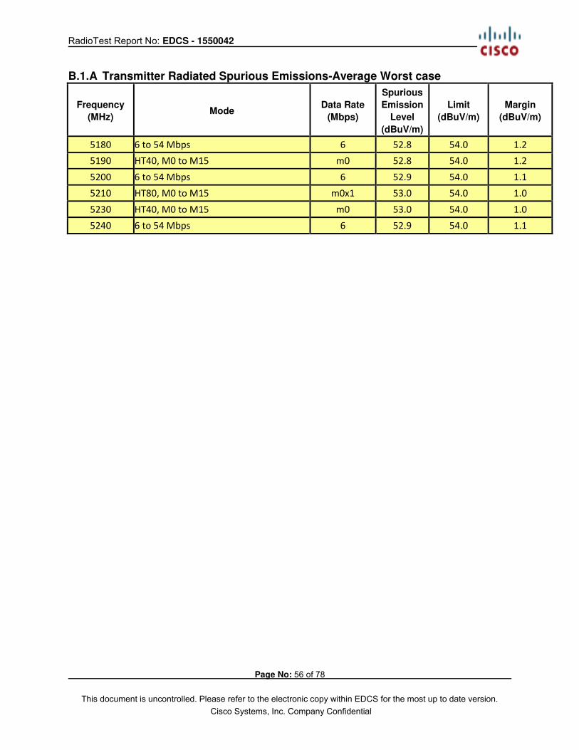
B1 Radiated Spurious Emissions 15.205 / 15.407 Radiated emissions which fall in the restricted bands, as defined in Section
15.205(a), must also comply with the radiated emission limits specified in Section 15.209(a) (see Section 15.205(c)).
Using Vasona, configure the spectrum analyzer as shown below (be sure to enter all losses between the transmitter output and the spectrum analyzer). Place the radio in continuous transmit mode.
Span: 1GHz – 18 GHz Reference Level: 80 dBuV Attenuation: 10 dB Sweep Time: Coupled Resolution Bandwidth: 1MHz Video Bandwidth: 3 MHz for peak, 1 kHz for average Detector: Peak Terminate the access Point RF ports with 50 ohm loads.
Maximize Turntable (find worst case table angle), Maximize Antenna (find worst case height) Save 2 plots: 1) Average Plot (Vertical and Horizontal), Limit= 54dBuV/m @3m
2) Peak plot (Vertical and Horizontal), Limit = 74dBuV/m @3m Place a marker at the end of the restricted band closest to the transmit frequency to show compliance. Also measure any emissions in the restricted bands.
This report represents the worst case data for all supported operating modes and antennas. There are no measurable emissions above 18 GHz. System
Number Description Samples
System under
test
Support
equipment
1 EUT S01 Support S02
Tested By :
Jose Aguirre Date of testing:
10-Feb-2016 – 22-Feb-2016
Test Result : PASS
See Appendix C for list of test equipment
RadioTest Report No: EDCS - 1550042
Page No: 56 of 78
This document is uncontrolled. Please refer to the electronic copy within EDCS for the most up to date version. Cisco Systems, Inc. Company Confidential
B.1.A Transmitter Radiated Spurious Emissions-Average Worst case
Frequency
(MHz) Mode
Data Rate
(Mbps)
Spurious
Emission
Level
(dBuV/m)
Limit
(dBuV/m)
Margin
(dBuV/m)
5180 6 to 54 Mbps 6 52.8 54.0 1.2
5190 HT40, M0 to M15 m0 52.8 54.0 1.2
5200 6 to 54 Mbps 6 52.9 54.0 1.1
5210 HT80, M0 to M15 m0x1 53.0 54.0 1.0
5230 HT40, M0 to M15 m0 53.0 54.0 1.0
5240 6 to 54 Mbps 6 52.9 54.0 1.1
RadioTest Report No: EDCS - 1550042
Page No: 57 of 78
This document is uncontrolled. Please refer to the electronic copy within EDCS for the most up to date version. Cisco Systems, Inc. Company Confidential
B.1.A.1 Radiated Transmitter Spurs, 5180 MHz, 6 to 54 Mbps , Average (1-18GHz) Worst Case 20MHz BW
B.1.A.2 Radiated Transmitter Spurs, 5190 MHz, HT40, M0 to M15, Average (1-18GHz) Worst Case 40MHz BW
RadioTest Report No: EDCS - 1550042
Page No: 58 of 78
This document is uncontrolled. Please refer to the electronic copy within EDCS for the most up to date version. Cisco Systems, Inc. Company Confidential
B.1.A.3 Radiated Transmitter Spurs, 5200 MHz, 6 to 54 Mbps , Average (1-18GHz) Worst Case 20MHz BW
B.1.A.4 Radiated Transmitter Spurs, 5210 MHz, HT80, M0 to M15, Average (1-18GHz) Worst Case 20MHz BW
RadioTest Report No: EDCS - 1550042
Page No: 59 of 78
This document is uncontrolled. Please refer to the electronic copy within EDCS for the most up to date version. Cisco Systems, Inc. Company Confidential
B.1.A.5 Radiated Transmitter Spurs, 5230 MHz, HT40, M0 to M15, Average (1-18GHz) Worst Case 40MHz BW
B.1.A.6 Radiated Transmitter Spurs, 5240 MHz, 6 to 54 Mbps , Average (1-18GHz) Worst Case 20MHz BW
RadioTest Report No: EDCS - 1550042
Page No: 60 of 78
This document is uncontrolled. Please refer to the electronic copy within EDCS for the most up to date version. Cisco Systems, Inc. Company Confidential
B.1.A.7 Radiated Transmitter Spurs, All rate, All modes, Average (18-26.5GHz)
B.1.A.8 Radiated Transmitter Spurs, All rate, All modes, Average (26.5- 40GHz)
RadioTest Report No: EDCS - 1550042
Page No: 61 of 78
This document is uncontrolled. Please refer to the electronic copy within EDCS for the most up to date version. Cisco Systems, Inc. Company Confidential
B.1.P Transmitter Radiated Spurious Emissions-Peak Worst Case
Frequency
(MHz) Mode
Data Rate
(Mbps)
Spurious
Emission
Level
(dBuV/m)
Limit
(dBuV/m)
Margin
(dBuV/m)
5180 6 to 54 Mbps 6 64.1 74.0 9.9
5190 HT40, M0 to M23 m0 64.0 74.0 10.0
5200 6 to 54 Mbps 6 63.2 74.0 10.8
5210 HT80, M0 to M23 m0x1 65.3 74.0 8.7
5230 HT40, M0 to M23 m0 64.7 74.0 9.3
5240 6 to 54 Mbps 6 64.3 74.0 9.7
RadioTest Report No: EDCS - 1550042
Page No: 62 of 78
This document is uncontrolled. Please refer to the electronic copy within EDCS for the most up to date version. Cisco Systems, Inc. Company Confidential
B.1.P.1 Radiated Transmitter Spurs, 5180 MHz, 6 to 54 Mbps , (1-18GHz) Worst Case 20MHz BW
B.1.P.2 Radiated Transmitter Spurs, 5190 MHz,HT40, M0 to M15, Peak (1-18GHz) Worst Case 20MHz BW
RadioTest Report No: EDCS - 1550042
Page No: 63 of 78
This document is uncontrolled. Please refer to the electronic copy within EDCS for the most up to date version. Cisco Systems, Inc. Company Confidential
B.1.P.3 Radiated Transmitter Spurs, 5200 MHz, 6 to 54 Mbps , (1-18GHz) Worst Case 20MHz BW
B.1.P.4 Radiated Transmitter Spurs, 5210 MHz,HT80, M0 to M15, Peak (1-18GHz) Worst Case 20MHz BW
RadioTest Report No: EDCS - 1550042
Page No: 64 of 78
This document is uncontrolled. Please refer to the electronic copy within EDCS for the most up to date version. Cisco Systems, Inc. Company Confidential
B.1.P.5 Radiated Transmitter Spurs, 5230 MHz,HT40, M0 to M15, Peak (1-18GHz) Worst Case 20MHz BW
B.1.P.6 Radiated Transmitter Spurs, 5240 MHz, 6 to 54 Mbps , Peak (1-18GHz) Worst Case 20MHz BW
RadioTest Report No: EDCS - 1550042
Page No: 65 of 78
This document is uncontrolled. Please refer to the electronic copy within EDCS for the most up to date version. Cisco Systems, Inc. Company Confidential
B.1.P.7 Radiated Transmitter Spurs, All rate, All modes, Peak (18-26.5GHz) Horizontal & Vertical
B.1.P.8 Radiated Transmitter Spurs, All rate, All modes, Peak (26.5-40GHz) Horizontal & Vertical
RadioTest Report No: EDCS - 1550042
Page No: 66 of 78
This document is uncontrolled. Please refer to the electronic copy within EDCS for the most up to date version. Cisco Systems, Inc. Company Confidential
B.2 Radiated Emissions 30MHz to 1GHz 15.209 / 15.205 / 15.407: Radiated emissions which fall in the restricted bands, as defined in Section 15.205(a), must also comply with the radiated emission limits specified in Section 15.209(a) (see Section 15.205(c)).
Ref. ANSI C63.10: 2013 section 6.5
Using Vasona, configure the spectrum analyzer as shown below (be sure to enter all losses between the transmitter output and the spectrum analyzer). Place the radio in continuous transmit mode.
Span: 30MHz – 1GHz Reference Level: 80 dBuV Attenuation: 10 dB Sweep Time: Coupled Resolution Bandwidth: 100kHz Video Bandwidth: 300kHz Detector: Peak for Pre-scan, Quasi-Peak
. Compliance shall be determined using CISPR quasi-peak detection; however, peak detection is permitted as an alternative to quasi-peak detection.
Terminate the access Point RF ports with 50 ohm loads.
Maximize Turntable (find worst case table angle), Maximize Antenna (find worst case height)
This report represents the worst case data for all supported operating modes and antennas. System # Description Samples
1 EUT S01
2 Support Power Supply S02 Tested By :
Jose Aguirre Date of testing:
10-Feb-2016 – 22-Feb-2016
Test Result : PASS
See Appendix C for list of test equipment
RadioTest Report No: EDCS - 1550042
Page No: 67 of 78
This document is uncontrolled. Please refer to the electronic copy within EDCS for the most up to date version. Cisco Systems, Inc. Company Confidential
Test Result Frequency
MHz
Raw
dBuV
Cable
Loss
AF
dB
Level
dBuV/m
Measurement
Type
P
ol
Hgt
cm
Azt
Deg
Limit
dBuV/m
Margin
dB
Pass
/Fail
54.078 20.53 0.7 7.34 28.57 Quasi Max V 115 0 40 -11.43 Pass
988.36 0.26 3
23.1
7 26.43 Quasi Max H 101 223 54 -27.57 Pass
30 -0.76 0.49 21.7 21.44 Quasi Max V 262 343 40 -18.56 Pass
RadioTest Report No: EDCS - 1550042
Page No: 68 of 78
This document is uncontrolled. Please refer to the electronic copy within EDCS for the most up to date version. Cisco Systems, Inc. Company Confidential
B.3 AC Conducted Emissions
15.207
Except when the requirements applicable to a given device state otherwise, for any radio apparatus equipped to operate from the public utility AC power supply, either directly or indirectly (such as with a battery charger), the radio frequency voltage of emissions conducted back onto the AC power lines in the frequency range of 0.15 MHz to 30 MHz shall not exceed the limits shown in the table in these sections. The more stringent limit applies at the frequency range boundaries. Measurement Procedure Accordance with ANSI C63.10:2013 section 6.2
Using Vasona, configure the spectrum analyzer as shown below (be sure to enter all losses between the transmitter output and the spectrum analyzer). Place the radio in continuous transmit mode.
Span: 150 KHz – 30 MHz Attenuation: 10 dB Sweep Time: Coupled Resolution Bandwidth: 9 KHz Video Bandwidth: 30 KHz Detector: Quasi-Peak / Average
This report represents the worst case data for all supported operating modes.
System # Description Samples
1 EUT S01
2 Support Power Supply S02
Tested By :
Jose Aguirre Date of testing:
10-Feb-2016 – 22-Feb-2016 Test Result : Pass
RadioTest Report No: EDCS - 1550042
Page No: 69 of 78
This document is uncontrolled. Please refer to the electronic copy within EDCS for the most up to date version. Cisco Systems, Inc. Company Confidential
Test Results Frequency
MHz
Raw
dBuV
Cable
Loss
Factors
dB
Level
dBuV
Measurement
Type Line
Limit
dBuV
Margin
dB
Pass
/Fail
0.320966 20.09 20.31 0.05 40.45 Quasi Peak Live 59.68 -19.23 Pass
0.19578 27.1 20.86 0.05 48.02 Quasi Peak Live 63.79 -15.77 Pass
6.845766 20.05 20.01 0.07 40.13 Quasi Peak Live 60 -19.87 Pass
1.169166 20.05 19.9 0.04 40 Quasi Peak Live 56 -16 Pass
0.845716 20.19 19.92 0.03 40.14 Quasi Peak Live 56 -15.86 Pass
1.826544 18.25 19.9 0.03 38.18 Quasi Peak Live 56 -17.82 Pass
0.449884 20.41 19.94 0.04 40.39 Quasi Peak Live 56.88 -16.49 Pass
19.316794 16.23 20.3 0.2 36.73 Quasi Peak Live 60 -23.27 Pass
0.193098 27.03 20.88 0.06 47.97 Quasi Peak
Neutra
l 63.9 -15.93 Pass
1.167132 20.1 19.9 0.04 40.05 Quasi Peak
Neutra
l 56 -15.95 Pass
0.451342 20.56 19.94 0.04 40.53 Quasi Peak
Neutra
l 56.85 -16.32 Pass
19.304428 16.11 20.3 0.2 36.61 Quasi Peak
Neutra
l 60 -23.39 Pass
1.805952 17.96 19.9 0.03 37.89 Quasi Peak
Neutra
l 56 -18.11 Pass
0.32174 19.74 20.31 0.04 40.1 Quasi Peak
Neutra
l 59.66 -19.56 Pass
0.840658 20.25 19.92 0.03 40.2 Quasi Peak
Neutra
l 56 -15.8 Pass
6.826092 19.97 20.01 0.07 40.05 Quasi Peak
Neutra
l 60 -19.95 Pass
0.320966 16.38 20.31 0.05 36.74 Average Live 49.68 -12.94 Pass
0.19578 18.65 20.86 0.05 39.57 Average Live 53.79 -14.22 Pass
6.845766 14.78 20.01 0.07 34.87 Average Live 50 -15.13 Pass
1.169166 15.34 19.9 0.04 35.29 Average Live 46 -10.71 Pass
0.845716 16.15 19.92 0.03 36.1 Average Live 46 -9.9 Pass
1.826544 12.68 19.9 0.03 32.61 Average Live 46 -13.39 Pass
0.449884 16.69 19.94 0.04 36.67 Average Live 46.88 -10.21 Pass
19.316794 4.26 20.3 0.2 24.76 Average Live 50 -25.24 Pass
0.193098 18.24 20.88 0.06 39.18 Average
Neutra
l 53.9 -14.72 Pass
1.167132 15.66 19.9 0.04 35.6 Average
Neutra
l 46 -10.4 Pass
RadioTest Report No: EDCS - 1550042
Page No: 70 of 78
This document is uncontrolled. Please refer to the electronic copy within EDCS for the most up to date version. Cisco Systems, Inc. Company Confidential
0.451342 18.28 19.94 0.04 38.25 Average
Neutra
l 46.85 -8.6 Pass
19.304428 4.24 20.3 0.2 24.75 Average
Neutra
l 50 -25.25 Pass
1.805952 12.45 19.9 0.03 32.38 Average
Neutra
l 46 -13.62 Pass
0.32174 15.6 20.31 0.04 35.95 Average
Neutra
l 49.66 -13.71 Pass
0.840658 15.4 19.92 0.03 35.35 Average
Neutra
l 46 -10.65 Pass
6.826092 14.71 20.01 0.07 34.8 Average
Neutra
l 50 -15.2 Pass
RadioTest Report No: EDCS - 1550042
Page No: 71 of 78
This document is uncontrolled. Please refer to the electronic copy within EDCS for the most up to date version. Cisco Systems, Inc. Company Confidential
Photographs of Setup
Title: Conducted Test Setup
This is a dual band 2.4GHz / 5GHz device. All ports in this test set up photo are connected as all testing is automated. Section 2.6 of this test report given an overview of the different Tx antenna combinations used by this device.
RadioTest Report No: EDCS - 1550042
Page No: 72 of 78
This document is uncontrolled. Please refer to the electronic copy within EDCS for the most up to date version. Cisco Systems, Inc. Company Confidential
AIR-AP3802I-B-K9 AC Mains Conducted Emissions setup
RadioTest Report No: EDCS - 1550042
Page No: 73 of 78
This document is uncontrolled. Please refer to the electronic copy within EDCS for the most up to date version. Cisco Systems, Inc. Company Confidential
This document is uncontrolled. Please refer to the electronic copy within EDCS for the most up to date version. Cisco Systems, Inc. Company Confidential
This document is uncontrolled. Please refer to the electronic copy within EDCS for the most up to date version. Cisco Systems, Inc. Company Confidential
Appendix C: List of Test Equipment Used to perform the test
Equip# Manufacturer/ Model Description Last Cal Next Due Test Item
Huber + Suhner N Type Cable 18GHz 24-Aug-15 24-Aug-16 B.3
CIS021117 UFB311A-0-2484-520520
Micro-Coax RF Coaxial Cable, to 18GHz, 248.4 in 24-Aug-15 24-Aug-16 B.3
CIS044940 ESU40
Rohde & Schwarz EMI Test Receiver, 20Hz-40GHz 2-Nov-15 2-Nov-16 B.3
CIS054647 33-605
Stanley 10meter Measuring Tape Cal not
required Cal not
required B.3
CIS018963 CNE V
York Comparison Noise Emitter, 30 - 1000MHz Cal not
required Cal not
required B.3
Test Equipment used for RF Conducted Tests
Equip No
Model
Manufacturer Description Last Cal Next Cal Test Item
CIS050721 N9030A PXA Signal Analyzer 13-Apr-15 13-Apr-16 A1 thru A4
RadioTest Report No: EDCS - 1550042
Page No: 76 of 78
This document is uncontrolled. Please refer to the electronic copy within EDCS for the most up to date version. Cisco Systems, Inc. Company Confidential
Keysight
CIS054662 SF18-S1S1-36 MegaPhase SMA 36" cable 24-Sep-15 24-Sep-16
A1 thru A4
CIS054663 F120-S1S1-48 MegaPhase SMA 48" Cable 25-Sep-15 25-Sep-16
A1 thru A4
CIS054665 RA08-S1S1-24 MegaPhase SMA 24" Cable 25-Sep-15 25-Sep-16
A1 thru A4
CIS054666 RA08-S1S1-18 MegaPhase SMA 18" Cable 25-Sep-15 25-Sep-16
A1 thru A4
CIS054667 RA08-S1S1-18 MegaPhase SMA 18" Cable 25-Sep-15 25-Sep-16
A1 thru A4
CIS054668 RA08-S1S1-18 MegaPhase SMA 18" Cable 25-Sep-15 25-Sep-16
A1 thru A4
CIS054669 RA08-S1S1-18 MegaPhase SMA 18" Cable 25-Sep-15 25-Sep-16
A1 thru A4
CIS054670 RA08-S1S1-12 MegaPhase SMA 12" Cable 25-Sep-15 25-Sep-16
A1 thru A4
CIS054671 RA08-S1S1-12 MegaPhase SMA 12" Cable 25-Sep-15 25-Sep-16
A1 thru A4
CIS054672 RA08-S1S1-12 MegaPhase SMA 12" Cable 25-Sep-15 25-Sep-16
A1 thru A4
CIS054673 RA08-S1S1-12 MegaPhase SMA 12" Cable 25-Sep-15 25-Sep-16
A1 thru A4
CIS054674 RA08-S1S1-12 MegaPhase SMA 12" Cable 25-Sep-15 25-Sep-16
A1 thru A4
CIS054675 RA08-S1S1-12 MegaPhase SMA 12" Cable 25-Sep-15 25-Sep-16
A1 thru A4
CIS054677 RA08-S1S1-12 MegaPhase SMA 12" Cable 25-Sep-15 25-Sep-16
A1 thru A4
CIS054678 RA08-S1S1-12 MegaPhase SMA 12" Cable 25-Sep-15 25-Sep-16
A1 thru A4
CIS054686 NI PXI-2796 National Instruments Plug-in switch module 6-Oct-15 6-Oct-16
A1 thru A4
CIS055094 PXI-1042 National Instruments Chassis Cal Not Required Cal Not Required
A1 thru A4
CIS055117 RFLT2WDC40G RF Lambda 2 Way 40GHz Splitter 11-Nov-15 11-Nov-16
A1 thru A4
CIS055166 RFLT4WDC40GK RF Lambda 4 Way Power Divider 40GHz 23-Nov-15 23-Nov-16
A1 thru A4
CIS054656 BRC50705-02 Micro-Tronics Band Reject Filter 24-Sep-15 24-Sep-16
A1 thru A4
CIS054655 BRC50704-02 Micro-Tronics
Notch Filter, SB:5.470-5.725GHz, to 12GHz 24-Sep-15 24-Sep-16
A1 thru A4
CIS054654 BRC50703-02 Micro-Tronics
Notch Filter, SB:5.150-5.350GHz, to 11GHz 24-Sep-15 24-Sep-16
A1 thru A4
CIS054653 BRM50702-02 Micro-Tronics
Notch Filter, SB:2.400-2.500GHz, to 18GHz 24-Sep-15 24-Sep-16
This document is uncontrolled. Please refer to the electronic copy within EDCS for the most up to date version. Cisco Systems, Inc. Company Confidential
Appendix E: Abbreviation Key and Definitions
The following table defines abbreviations used within this test report.
Abbreviation Description Abbreviation Description
EMC Electro Magnetic Compatibility F Degrees Fahrenheit EMI Electro Magnetic Interference C Degrees Celsius EUT Equipment Under Test Temp Temperature ITE Information Technology Equipment S/N Serial Number TAP Test Assessment Schedule Qty Quantity ESD Electro Static Discharge emf Electromotive force EFT Electric Fast Transient RMS Root mean square EDCS Engineering Document Control
System Qp Quasi Peak
Config Configuration Av Average CIS# Cisco Number (unique identification
number for Cisco test equipment) Pk Peak
Cal Calibration kHz Kilohertz (1x10³) EN European Norm MHz MegaHertz (1x10⁶) IEC International Electro technical
Commission GHz Gigahertz (1x10⁹)
CISPR International Special Committee on Radio Interference
H Horizontal
CDN Coupling/Decoupling Network V Vertical LISN Line Impedance Stabilization
Network dB decibel
PE Protective Earth V Volt GND Ground kV Kilovolt (1x10³) L1 Line 1 V Microvolt (1x10⁻⁶) L2 Line2 A Amp L3 Line 3 A Micro Amp (1x10⁻⁶) DC Direct Current mS Milli Second (1x10⁻³) RAW Uncorrected measurement value,
as indicated by the measuring device
S Micro Second (1x10⁻⁶)
RF Radio Frequency S Micro Second (1x10⁻⁶) SLCE Signal Line Conducted Emissions m Meter Meas dist Measurement distance Spec dist Specification distance N/A or NA Not Applicable SL Signal Line (or Telecom Line) P Power Line L Live Line N Neutral Line R Return S Supply AC Alternating Current
RadioTest Report No: EDCS - 1550042
Page No: 78 of 78
This document is uncontrolled. Please refer to the electronic copy within EDCS for the most up to date version. Cisco Systems, Inc. Company Confidential