Page 1
INTERNATIONAL JOURNAL OF PRECISION ENGINEERING AND MANUFACTURING Vol. 14, No. 3, pp. 501-504 MARCH 2013 / 501
© KSPE and Springer 2013
Air-breathing Flexible Polydimethylsiloxane (PDMS)-
based Fuel Cell
Ikwhang Chang1, Min Hwan Lee2, Ji-Hyun Lee3, Youn-Sang Kim3,4, and Suk Won Cha5,#
1 Department of Intelligent Convergence Systems, Seoul National University, Gwanakro 1, Gwanak-gu, Seoul, Republic of Korea, 151-7442 School of Engineering, University of California, Merced, 5200 North Lake Road, Merced, California 95343, USA
3 Department of Nano Convergence, Seoul National University, Gwanakro 1, Gwanak-gu, Seoul, Republic of Korea, 151-7444 Advanced Institute of Convergence Technology, 64-1 Iui-dong, Yeongtong-gu, Suwon-si, Gyeonggi-do, Republic of Korea, 443-270
5 Department of Mechanical and Aerospace Engineering, Seoul National University, Gwanakro 1, Gwanak-gu, Seoul, Republic of Korea, 151-744# Corresponding Author / E-mail: [email protected] , TEL: +82-2-880-1700, FAX: +82-2-880-1696
KEYWORDS: Polydimethylsiloxane (PDMS), Flexible fuel cell, Air-breathing, Polymer Electrolyte Fuel Cell (PEFC)
The paper examines a fabrication method of flexible fuel cells (FCs), and its feasibility through a set of electrical measurements both
in the as-prepared and the bended condition. The flexible FC consists of three parts: membrane electrode assembly (MEA), anode
and cathode endplates with current collectors. The endplate material for anode and cathode used in this study is Polydimethylsiloxane
(PDMS), and metallic films are sputtered on a patterned PDMS to use the resulting structure as current collector. The power density
of bended cell with the curvature of ~1.8 m-1
decreased by ~30% compared to the as-prepared (non-bended) cell.
Manuscript received: July 2, 2012 / Accepted: December 11, 2012
1. Introduction
Among various renewable energy devices, fuel cells (FCs) are
considered one of the most promising direct energy conversion devices
generating electrical energy because of its low carbon emission and
high efficiency.1-3 In particular, polymer electrolyte fuel cells (PEFCs)
are known to have the highest output power density and cell
durability.4-6 Even more they are considered to be the most plausible
type for mobile applications due to its low temperature operation. To be
usable as a mobile/portable devices, the system needs to be simple,
easy to exchange fuel, and stable in performance regardless of
surrounding conditions.7,8 Recently, the need of flexible devices surges
for a variety of applications including energy devices, and flexible
substrates such as polymers and metal foils have gained more attention
gradually for flexible displays and electronic sensors.9-11 The meaning
of the term “flexibility” is categorized roughly into three categories:
how much a system of interest is bendable, permanently shaped, or
elastically stretchable. Among these meanings, studies related to
flexible electronics involve generally either bendable or stretchable
levels.12 Among flexible substrates such as glass, plastic film and metal
foil, flexible electronics based on Polydimethylsiloxane (PDMS) have
been investigated widely by many research groups.13-17 Rodgers et al.
highlighted many researches related to bio-integrated electronics and
optical electronics based on flexible substrate.18,19 Wheldon et al.
originally reported that H2-O2 flexible FCs with 10-100 mm2 active
area, and its peak power density was 57 mW/cm2.20 This study
suggested a simple stack configuration with a single cell which uses
organic material and Au plated Cu mesh. In this paper, PDMS was
employed as the material for endplates in polymer based fuel cells.
PDMS, comprised of silicone elastomer with a low Young’s modulus,
can be patterned via 3-dimensional nano-patterning and lithography.16,18,19
Moreover, we investigated the possible use of PDMS as flexible
endplates for fuel cells to take advantage of the flexibility of PDMS.
Although several studies demonstrated micro fuel cells based on
PDMS, our report presents a fabrication method of a flexible PDMS-
based fuel cell and demonstrates the performance feasibility under
bendable/non-bendable conditions in air-breathing flexible electrolyte
fuel cell for the first time.21,22 We confirmed a critical design issues
relative to the performance losses in our studies. Also, the experimental
methods and preparation processes were proposed.
2. Fabrication and experimental procedure
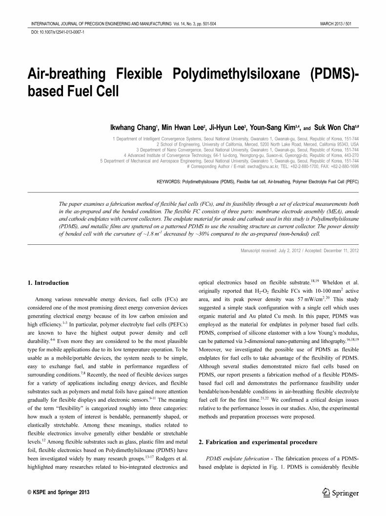
PDMS endplate fabrication - The fabrication process of a PDMS-
based endplate is depicted in Fig. 1. PDMS is considerably flexible
DOI: 10.1007/s12541-013-0067-1
Page 2
502 / MARCH 2013 INTERNATIONAL JOURNAL OF PRECISION ENGINEERING AND MANUFACTURING Vol. 14, No. 3
(360-870 KPa) compared to other candidates for endplate material such
as polycarbonate (2.4 GPa), graphite (10 GPa) and stainless steel
(190 GPa).23,24 The dimension of PDMS endplate is 45 mm × 45 mm.
The base mold made of stainless steel was covered with a mixture of
PDMS and curing agent. Since it is difficult to lift off a comb-like
structure with high depth-to-width aspect ratio due to a significant
adhesion at the side walls of flow channels, the dimensions of PDMS-
endplate were chosen to ease the lift-off process. The width, depth (or
height) and length of H2 flow channel at the anode side were 1, 1 and
30 mm, respectively, and those of cathode(rectangle hole type) was 2.5,
6 and 28 mm. Since the cathode side is open to air without forced air
injection/compression system (i.e., air-breathing type) and oxygen
reduction reaction at the cathode is usually known to cause one of the
most significant losses, the open area was designed to be wider.25
However, the requirement of structural stability limited the maximum
open area and thus, we compromised some of fluent mass transport by
having the portion of open area to be less than 50% (for our
experiment, it was ~38%) whereby the clamping force can be conveyed
well through to the MEA.25 The PDMS and a curing agent were mixed
with the ratio of 10:1 in an experimental dish, and heated at 70oC for
4 hours (Fig. 1(b)). After 5 min sonication in ethanol solution, thin-film
metals layers that act as current collector were deposited on PDMS via
DC sputtering method. The target-substrate distance was 6 cm and
sputter deposition power was 200 W under 5 mtorr Ar pressure. First,
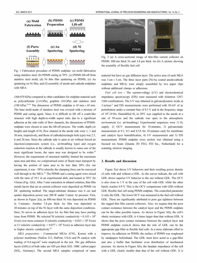
as shown in Figure 2(a), an 880 nm thick Ni was deposited on PDMS
in 5 minutes. Another 3.8 μm thick Au film was deposited in
20 minutes on top of the Ni layer with the same deposition conditions.
Here, Ni serves as adhesion layer for Au film that may have peeling
issue from PDMS. We selected Ni (electric conductivity = 0.143 × 10⁶
S/cm) over more common Ti (electric conductivity = 0.023 × 10⁶ S/cm)
or Cr (electric conductivity = 0.077 × 10⁶ S/cm) as adhesion layer due
to higher electric conductivity.26
MEA preparation - Commercial MEAs (CNL, Korea) with a
polymer membrane (Nafion 212, DuPont, USA) and Pt catalyst with
loading of 0.4 mg/cm2 were employed in the test. The gas diffusion
layers (GDLs) of both sides are 420 μm thick SGL 10BC carbon paper
(SGL, Germany). The second MEA samples comprised of same
material but have no gas diffusion layer. The active area of each MEA
was 3 cm × 3 cm. The three layer parts (Ni/Au coated anode/cathode
endplates and MEA) were simply assembled by two paper clips
without additional clamps or adhesions.
Fuel cell test - The current-voltage (I-V) and electrochemical
impedance spectroscopy (EIS) were measured with Solartron 1287/
1260 combinations. The I-V was obtained in galvanodynamic mode at
3 mAsec-1 and EIS measurements were performed with 30 mV of ac
perturbation under a constant bias of 0.3 V and in the frequency range
of 105-10 Hz. Humidified H2 in 20oC was supplied to the anode at a
rate of 50 sccm and the cathode was open to the atmospheric
environment (i.e. air-breathing). Experimental sequences were 1) H2
supply, 2) OCV measurement for 10 minutes, 3) galvanostatic
measurement at 0.1, 0.3 and 0.5A for 10 minutes each for membrane
and catalyst layer humidification, 4) I-V measurement and 5) EIS
measurement. PDMS endplate cross section was obtained using a
focused ion beam (Quanta 3D FEG; FEI Inc., Netherland) for a
scanning electron imaging.
3. Results and discussion
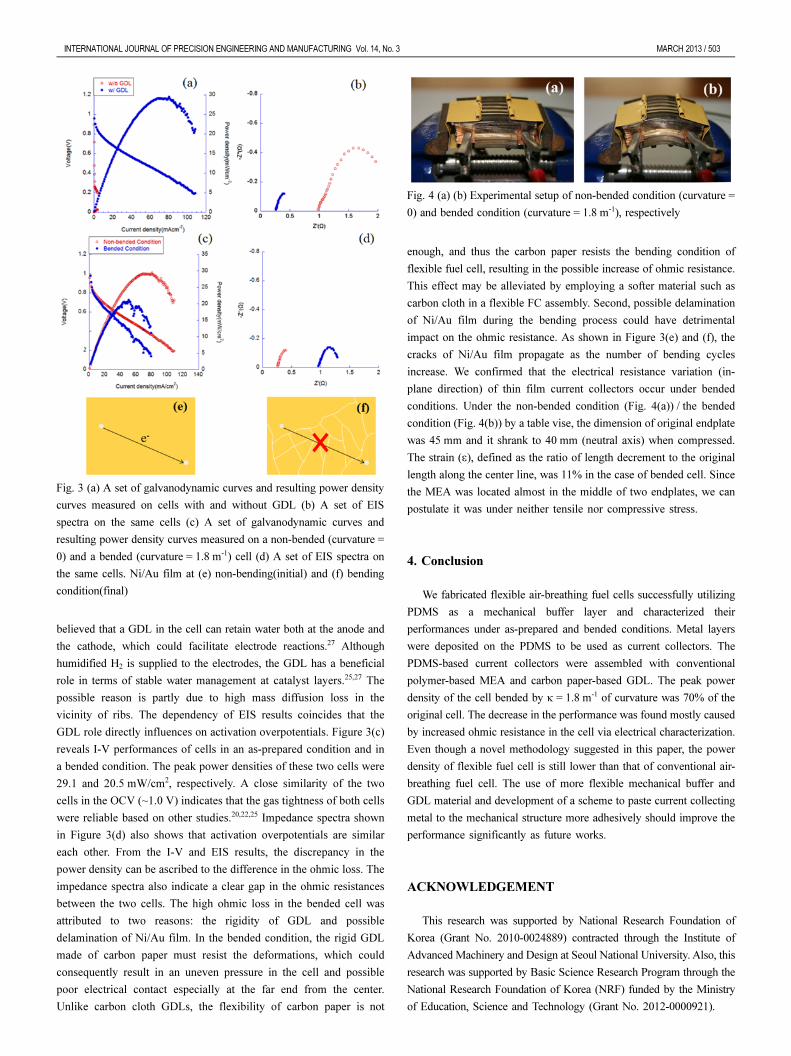
Figure 3(a) shows I-V behaviors and their resulting power density
of cells with and without a GDL. As the curves indicate, the cell with
GDL shows superior I-V behavior to the one without GDL. The OCV
is also close to 1 V in the case of the cell with GDL while the other
barely reaches 0.9 V. This is the OCV comparisons with GDL/without
GDL flexible fuel cell using PDMS endplate. The controlled parameter
is only the GDL. The lower OCV was measured in the fuel cell without
GDL. These are significantly attributed to poor gas tightness between
the rugged thin film current collectors. Also, we suspect that the poor
contact resistance between the catalyst layer and the PDMS endplate
can be the other possible reason. As shown in Figure 3(b), the cell’s
ohmic resistance with GDL is 4 times larger than that without GDL. It
shows that the poor contact resistance between the catalyst layer and
PDMS endplate exists.It shows that the role of GDL can be the
appropriate gap filler in flexible fuel cells. In a more elaborate effort to
improve Au adhesion on PDMS, the surface of PDMS was roughened
by sandpapers beforehand. The GDL must have acted as a gap-filler
and also a buffer that facilitates even distribution of mechanical
pressure. As shown in Figure 3(b), the faradaic impedance of the cell
with a GDL clearly smaller than that of the cell without GDL. It is
Fig. 1 Fabrication procedure of PDMS endplate: (a) mold fabrication
using stainless steel, (b) PDMS curing at 70oC, (c) PDMS lift-off from
stainless steel mold, (d) Ni thin film sputtering on PDMS, (e) Au
sputtering on Ni film, and (f) assembly of anode and cathode endplates
with MEA
Fig. 2 (a) A cross-sectional image of thin-film current collector on
PDMS: 880 nm thick Ni and 3.8 μm thick Au (b) A picture showing
the assembly of flexible fuel cell
Page 3
INTERNATIONAL JOURNAL OF PRECISION ENGINEERING AND MANUFACTURING Vol. 14, No. 3 MARCH 2013 / 503
believed that a GDL in the cell can retain water both at the anode and
the cathode, which could facilitate electrode reactions.27 Although
humidified H2 is supplied to the electrodes, the GDL has a beneficial
role in terms of stable water management at catalyst layers.25,27 The
possible reason is partly due to high mass diffusion loss in the
vicinity of ribs. The dependency of EIS results coincides that the
GDL role directly influences on activation overpotentials. Figure 3(c)
reveals I-V performances of cells in an as-prepared condition and in
a bended condition. The peak power densities of these two cells were
29.1 and 20.5 mW/cm2, respectively. A close similarity of the two
cells in the OCV (~1.0 V) indicates that the gas tightness of both cells
were reliable based on other studies.20,22,25 Impedance spectra shown
in Figure 3(d) also shows that activation overpotentials are similar
each other. From the I-V and EIS results, the discrepancy in the
power density can be ascribed to the difference in the ohmic loss. The
impedance spectra also indicate a clear gap in the ohmic resistances
between the two cells. The high ohmic loss in the bended cell was
attributed to two reasons: the rigidity of GDL and possible
delamination of Ni/Au film. In the bended condition, the rigid GDL
made of carbon paper must resist the deformations, which could
consequently result in an uneven pressure in the cell and possible
poor electrical contact especially at the far end from the center.
Unlike carbon cloth GDLs, the flexibility of carbon paper is not
enough, and thus the carbon paper resists the bending condition of
flexible fuel cell, resulting in the possible increase of ohmic resistance.
This effect may be alleviated by employing a softer material such as
carbon cloth in a flexible FC assembly. Second, possible delamination
of Ni/Au film during the bending process could have detrimental
impact on the ohmic resistance. As shown in Figure 3(e) and (f), the
cracks of Ni/Au film propagate as the number of bending cycles
increase. We confirmed that the electrical resistance variation (in-
plane direction) of thin film current collectors occur under bended
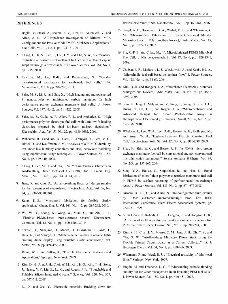
conditions. Under the non-bended condition (Fig. 4(a)) / the bended
condition (Fig. 4(b)) by a table vise, the dimension of original endplate
was 45 mm and it shrank to 40 mm (neutral axis) when compressed.
The strain (ε), defined as the ratio of length decrement to the original
length along the center line, was 11% in the case of bended cell. Since
the MEA was located almost in the middle of two endplates, we can
postulate it was under neither tensile nor compressive stress.
4. Conclusion
We fabricated flexible air-breathing fuel cells successfully utilizing
PDMS as a mechanical buffer layer and characterized their
performances under as-prepared and bended conditions. Metal layers
were deposited on the PDMS to be used as current collectors. The
PDMS-based current collectors were assembled with conventional
polymer-based MEA and carbon paper-based GDL. The peak power
density of the cell bended by κ = 1.8 m-1 of curvature was 70% of the
original cell. The decrease in the performance was found mostly caused
by increased ohmic resistance in the cell via electrical characterization.
Even though a novel methodology suggested in this paper, the power
density of flexible fuel cell is still lower than that of conventional air-
breathing fuel cell. The use of more flexible mechanical buffer and
GDL material and development of a scheme to paste current collecting
metal to the mechanical structure more adhesively should improve the
performance significantly as future works.
ACKNOWLEDGEMENT
This research was supported by National Research Foundation of
Korea (Grant No. 2010-0024889) contracted through the Institute of
Advanced Machinery and Design at Seoul National University. Also, this
research was supported by Basic Science Research Program through the
National Research Foundation of Korea (NRF) funded by the Ministry
of Education, Science and Technology (Grant No. 2012-0000921).
Fig. 3 (a) A set of galvanodynamic curves and resulting power density
curves measured on cells with and without GDL (b) A set of EIS
spectra on the same cells (c) A set of galvanodynamic curves and
resulting power density curves measured on a non-bended (curvature =
0) and a bended (curvature = 1.8 m-1) cell (d) A set of EIS spectra on
the same cells. Ni/Au film at (e) non-bending(initial) and (f) bending
condition(final)
Fig. 4 (a) (b) Experimental setup of non-bended condition (curvature =
0) and bended condition (curvature = 1.8 m-1), respectively
Page 4
504 / MARCH 2013 INTERNATIONAL JOURNAL OF PRECISION ENGINEERING AND MANUFACTURING Vol. 14, No. 3
REFERENCES
1. Baglio, V., Stassi, A., Matera, F. V., Kim, H., Antonucci, V., and
Arico, A. S., “AC-Impedance Investigation of Different MEA
Configurations for Passive-Mode DMFC Mini-Stack Applications,”
Fuel Cells, Vol. 10, No. 1, pp. 124-131, 2010.
2. Chang, I., Ha, S., Kim, J., Lee, J. Y., and Cha, S. W., “Performance
evaluation of passive direct methanol fuel cell with methanol vapour
supplied through a flow channel,” J. Power Sources, Vol. 184, No. 1,
pp. 9-15, 2008.
3. Tsuchiya, M., Lai, B.-K., and Ramanathan, S., “Scalable
nanostructured membranes for solid-oxide fuel cells,” Nat.
Nanotechnol., Vol. 6, pp. 282-286, 2011.
4. Saha, M. S., Li, R., and Sun, X., “High loading and monodispersed
Pt nanoparticles on multiwalled carbon nanotubes for high
performance proton exchange membrane fuel cells,” J. Power
Sources, Vol. 177, No. 2, pp. 314-322, 2008.
5. Saha, M. S., Gullá, A. F., Allen, R. J., and Mukerjee, S., “High
performance polymer electrolyte fuel cells with ultra-low Pt loading
electrodes prepared by dual ion-beam assisted deposition,”
Electrochim. Acta, Vol. 51, No. 22, pp. 4680-4692, 2006.
6. Wahdame, B., Candusso, D., Harel, F., François, X., Péra, M.-C.,
Hissel, D., and Kauffmann, J.-M., “Analysis of a PEMFC durability
test under low humidity conditions and stack behaviour modelling
using experimental design techniques,” J. Power Sources, Vol. 182,
No. 2, pp. 429-440, 2008.
7. Chang, I., Lee, M. H., and Cha, S. W., “Characteristics Behaviors on
Air-Breathing Direct Methanol Fuel Cells,” Int. J. Precis. Eng.
Manuf., Vol. 13, No. 7, pp. 1141-1144, 2012.
8. Jiang, R. and Chu, D., “An air-breathing H2/air cell design suitable
for fast screening of electrolytes,” Electrochim. Acta, Vol. 56, No.
24, pp. 8365-8370, 2011.
9. Kang, K.-S., “Micromold fabrication for flexible display
application,” Chem. Eng. J., Vol. 161, No. 1-2, pp. 289-292, 2010.
10. Wu, W. -Y., Zhong, X., Wang, W., Miao, Q., and Zhu, J. -J.,
“Flexible PDMS-based three-electrode sensor,” Electrochem.
Commun., Vol. 12, No. 11, pp. 1600-1604, 2010.
11. Sekitani, T., Nakajima, H., Maeda, H., Fukushima, T., Aida, T.,
Hata, K., and Someya, T., “Stretchable active-matrix organic light-
emitting diode display using printable elastic conductors,” Nat.
Mater., Vol. 8, pp. 494-499, 2009.
12. Wong, W. S. and Salleo, A., “Flexible Electronics: Materials and
Applications,” Springer, New York, 2009.
13. Kim, D.-H., Ahn, J.-H., Choi, W. M., Kim, H.-S., Kim, T.-H., Song,
J., Huang, Y. Y., Liu, Z., Lu, C., and Rogers, J. A., “Stretchable and
Foldable Silicon Integrated Circuits,” Science, Vol. 320, No. 357,
pp. 507-511, 2008.
14. Lu, X. and Xia, Y., “Electronic materials: Buckling down for
flexible electronics,” Nat. Nanotechnol., Vol. 1, pp. 163-164, 2006.
15. Siegel, A. C., Bruzewicz, D. A., Weibel, D. B., and Whitesides, G.
M., “Microsolidics: Fabrication of Three-Dimensional Metallic
Microstructures in Poly(dimethylsiloxane),” Adv. Mater., Vol. 19,
No. 5, pp. 727-733, 2007.
16. Siu, C.-P.-B. and Chiao, M., “A Microfabricated PDMS Microbial
Fuel Cell,” J. Microelectromech. S., Vol. 17, No. 6, pp. 1329-1341,
2008.
17. Choban, E. R., Markoski, L. J., Wieckowski, A., and Kenis, P. J. A.,
“Microfluidic fuel cell based on laminar flow,” J. Power Sources,
Vol. 128, No. 1, pp. 54-60, 2004.
18. Kim, D.-H. and Rodgers, J. A., “Stretchable Electronics: Materials
Strategies and Devices,” Adv. Mater., Vol. 20, No. 24, pp. 4887-
4892, 2008.
19. Shin, G., Jung, I., Malyarchuk, V., Song, J., Wang, S., Ko, H. C.,
Huang, Y., Ha, J. S., and Rogers, J. A., “Micromechanics and
Advanced Designs for Curved Photodetector Arrays in
Hemispherical Electronic-Eye Cameras,” Small, Vol. 6, No. 7, pp.
851-856, 2010.
20. Wheldon, J., Lee, W.-J., Lee, D.-H., Broste, A. B., Bollinger, M.,
and Smyrl, W. H., “High-Performance Flexible Miniature Fuel
Cell,” Electrochem. Solid St., Vol. 12, No. 5, pp. B86-B89, 2009.
21. Shah, K., Shin, W. C., and Besser, R. S., “A PDMS micro proton
exchange membrane fuel cell by conventional and non-conventional
microfabrication techniques,” Sensor Actuator B-Chem., Vol. 97,
No. 2-3, pp. 157-167, 2004.
22. Song, Y.-A., Batista, C., Sarpeshkar, R., and Han, J., “Rapid
fabrication of microfluidic polymer electrolyte membrane fuel cell
in PDMS by surface patterning of perfluorinated ion-exchange
resin,” J. Power Sources, Vol. 183, No. 2, pp. 674-677 2008.
23. Armani, D., Liu, C., and Aluru, N., “Re-configurable fluid circuits
by PDMS elastomer micromachining,” Proc. 12th IEEE
International Conference Micro Electro Mechanical Systems, pp.
222-227, 1999.
24. de las Heras, N., Roberts, E. P. L., Langton, R., and Hodgson, D. R.,
“A review of metal separator plate materials suitable for automotive
PEM fuel cells,” Energ. Environ. Sci., Vol. 2, pp. 206-214, 2009.
25. Kim, S. H., Cha, H. Y., Miesse, C. M., Jang, J. H., Oh, Y. S., and
Cha, S. W., “Air-Breathing Miniature Planar Stack using the
Flexible Printed Circuit Board as a Current Collector,” Int. J.
Hydrogen Energy, Vol. 34, No. 1, pp. 459-466, 2009.
26. Wissmann, P. and Frizel, H.-U., “Electrical resistivity of thin metal
films,” Springer, New York, 2007.
27. Paquin, M. and Frechette, L. G., “Understanding cathode flooding
and dry-out for water management in air breathing PEM fuel cells,”
J. Power Sources, Vol. 180, No. 1, pp. 440-451, 2008.