12
AIR CLASSIFIERS FOR CEMENT AND MINERALS CTC SERIES www.cemtec.at

AIR CLASSIFIERS FOR CEMENT AND MINERALS
CTC SERIES
w w w . c e m t e c . a t

w w w . c e m t e c . a t
CEMTEC – your partner for success.
CEMTEC supervises each project from start to finish. From planning to commissioning. Our product spectrum includes tube mills for grinding a wide range of bulk materials and minerals, as well as rotating drums for thermal treatment (calcination, drying, cooling) and mechanical processing (mixing, washing, conditioning, etc.) of different bulk materials. We also offer erection supervision, commissioning and technical support. Successful projects all over the world attest to the competence of CEMTEC.
CEMTEC manages projects for the cement and processing industry worldwide.
CEMTEC HEADQUARTERS AT ENNS AUSTRIA
CEMTEC operates on the basis of individual responsibility. Each member of our team is authorised to make high-level decisions. The entire responsibility for a project – from planning to commissioning – rests with a single person. This means that you will have the same, competent contact partner for all your queries, wishes and suggestions, without exception. In addition to standard orders, your individual requirements can also be fulfilled rapidly and without complications.

03
The design of this series was geared to optimized production, operating and maintenance costs. This was achieved by new combinations of rotor geometry and improved flow design. It is expressed in classifying efficiency, low bypass of fines (see Tromp‘s curves) and the resulting reduced pulverization and classification energy.
The corresponding stress design and optimisation by FEM simulations, together with vibration tests and modal analyses, guarantee the lowest possible maintenance costs on the one hand and optimised manufacturing costs on the other hand. This means that all series are designed so that the critical rotor speeds far exceed the maximum operating speed.
The optimised classification installation is supplemented by comprehensive advice for the required peripheral equipment, which plays a critical role in ensuring optimum production conditions.
Clas
sify
ing
effi c
ienc
y T
(x) %
Particle size x/µm
Machine:Class 10: grade effi ciency curve T(x)
CTC 185 OPC 1 d 75.00
55.00
25.00
CLAS
SIFI
ERS
The new CTC fine classifier series is based on the latest findings (4th generation) in the field of classification technology.
This series was developed by a team of experts with international experience and extensive know-how in machine and process engineering development and the design of air classifiers for classifying cement, slag, raw meal and other bulk mineral goods such as CaCO3 or dolomite, together with the required steps such as reconciliation with the grinding unit and configuration of the corresponding peripheral equipment (materials handling, air technology, product transport).
Classification in new dimensions

w w w . c e m t e c . a t
Extremely good top cut (d98) due to specially formed rotor blades and rotor labyrinth with sealing air
Low vibration level max. operating speed < n-critical
Low operating costs due to low speed levels
Reduced pressure loss due to optimised air-flow design (spiral housing and air guide vanes) and reduced speeds (curved rotor blades)Reduced power consumption due to reduced operating speed and pressure drop
Reduced wear due to reduced operating speeds and optimised wear protection on areas subject to stress, due to use of high-strength steels, compound liner plates and highly wear-resistant HVFB coatings on exposed areas (depending on respective application)
ADVA
NTA
GES
04Advantages of the CTC air classifier series
The newly developed CTC series (for fine industrial minerals d98=6-45 μm) is a new and innovative design which guarantees peak production with the finest quality and optimised operating costs.
The modular built classifier permits optimum tailor-made solutions for CEMTEC ball mills and vertical roller mills.
Since the classifier series are modular, versions with air feed from below are also possible (combined with the CEMTEC vertical roller mill series) or as a standalone solution for tailor-made applications.
Detail-oriented, sophisticated and practical solutions secure a number of advantages which are reflected in quality, low installation, production and maintenance costs.

In the classification zone the particles are subjected to two main forces- centrifugal force
Fc = dp3 * ρp * R * n2 * π3 / 5400
and
- drag force of the air
Fw = dp * 3π * ηg * vrad
dp particle diameterρp particle densityηg viscosity of the gasvrad radial speed of the gasR radius of classifying rotorn operation speed (rpm)
CENTRIFUGAL FORCE
CLASSIFICATION IN CENTRIFUGAL FORCE FIELD
DRAG FORCES (AIR)
FLOW DIRECTIONPARTICLE
The CTC series are designed as rod basket deflector wheel classifiers and geared to the varying requirements for cement, slag and raw meal classification. Particle sizes with a top cut (d98) as low as 30-25 μm are obtained for slag and cement.
In the CTC series the coarse fraction is fed into the classifying chamber via an air slide and distributor plate. The air flows tangentially into the classifying chamber via an aerodynamically configured spiral housing and air guide vanes, whereby the coarse fraction fed in from above is pre-accelerated and brought to rotor peripheral speed by the flow forces. In the classifying zone the coarse fraction is exposed for the main part to centrifugal, drag and flow forces.
FUN
CTIO
N
05General function of the CTC series
Centrifugal force predominate for particles larger than the cut size, and drag forces predominate for particles smaller than the cut size. The coarse particles fall spirally outside the rotor bowl into the coarse particle discharge, the finer particles are transported by the air flow through the rotor and fine particle discharge to the downstream classification devices.
In practice, the interaction of the classification forces is far more complex, because particle swarms (intensive dust clouds) rather than individual particles are subjected to the process.
With the appropriate engineering design the centrifugal force generated by the rotation of the classifier cage is amplified by effective flow configuration. This additionally reduces the possible cut size. The classifying rotor can then operate at a lower speed (with correspondingly less pressure loss).

w w w . c e m t e c . a t
GEN
ERAL
STR
UCT
UR
E
Classifiers consist of the main assemblies shown below. The classifier bearings can be lubricated by a circulatory oil lubrication system with integral oil cooler or by a grease lubrication system. This ensures adequate lubrication conditions over the entire speed range and for higher process temperatures.
06General structure and function of CTC classifiers
Rotor with specially shaped blades
Material feed with air slide and distributor plate
Rotor labyrinth seal
Spiral housing with guide vane ring (air intake)
Drive unit, motor, gears
Fine particle discharge with integral drive support
Storage unit
Coarse particle discharge
CTC
SER
IES
07
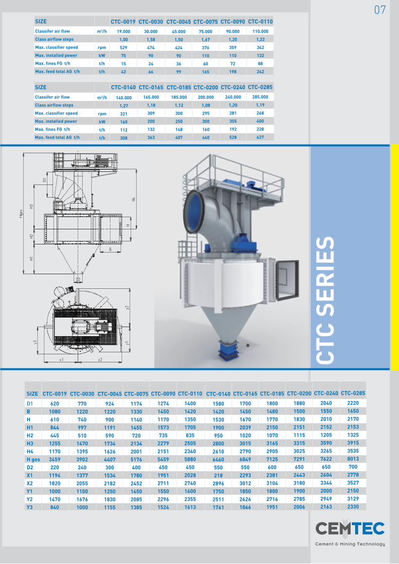
SIZE
Classifer air flow
Class airflow steps
Max. classifier speed
Max. installed power
Max. fines FG t/h
Max. feed total AG t/h
m3/h
rpm
kW
t/h
t/h
CTC-0185
185.000
1,12
300
250
148
407
CTC-0200
200.000
1,08
295
300
160
440
CTC-0240
240.000
1,20
281
355
192
528
CTC-0285
285.000
1,19
268
400
228
627
CTC-0165
165.000
1,18
309
200
132
363
CTC-0140
140.000
1,27
321
160
112
308
SIZE
Classifer air flow
Class airflow steps
Max. classifier speed
Max. installed power
Max. fines FG t/h
Max. feed total AG t/h
m3/h
rpm
kW
t/h
t/h
CTC-0045
45.000
1,50
424
90
36
99
CTC-0075
75.000
1,67
376
110
60
165
CTC-0090
90.000
1,20
359
110
72
198
CTC-0110
110.000
1,22
342
132
88
242
CTC-0030
30.000
1,58
474
90
24
66
CTC-0019
19.000
1,00
529
75
15
42
SIZE
D1BHH1H2H3H4H gesD2X1X2Y1Y2Y3
CTC-0045
9241220900
1191590
173416264407300
15342182125018301155
CTC-0075
1174133011401455720
213420015176400
17802452145020851385
CTC-0140
1580142015301900950
280026106460550218
2896175025111761
CTC-0200
18801500183021511115331530257291650
24433180190027852006
CTC-0090
1274145011701573735
227921515459450
19512711155022961524
CTC-0165
17001450167020391020301527906849550
22933012185026261866
CTC-0240
20401550201021521205359032657622650
26043344200029492163
CTC-0110
1400142013501705835
250523405880450
20282740160023551613
CTC-0185
18001480177021501070316529057125600
23813104180027161951
CTC-0285
22201650217021531325391535358013700
27783527215031292330
CTC-0030
7701220740997510
147013953902240
13772055110016761000
CTC-0019
6201080610844445
125511703459220
1194182010001470840

w w w . c e m t e c . a t
wf K/R/R rho = 2700 kg/m
10 g cement = 3000 Blaine
15 g cement = 4500 Blaine
100g
1000g
3000g
Range of cement classifi cation
Simplifi ed theoretical near-size particles depending on centrifugal acceleration and radial feed rate [V-rad]
1 10 100 1000
12,0
10,0
8,0
6,0
4,0
2,0
0,0
theor. near-size particles ~ d90 - d98 [µm]
Rad
ial a
ir v
eloc
ity [V
-rad
m/s
ec]
CTC ≈ 0019
CTC ≈ 0030
CTC ≈ 0045
CTC ≈ 0075
CTC ≈ 0090
CTC ≈ 0110
CTC ≈ 0140CTC ≈ 0165
CTC ≈ 0185
CTC ≈ 0200
CTC ≈ 0240
CTC ≈ 0285
Relationship of centrifugal acceleration to rotor speed for the CTC model series
Rotor speed [rpm]
Cent
rifu
gal a
ccel
erat
ion
0 100 1000
1000
100
10
1
NEA
R-S
IZE
PAR
TICL
ESCE
NTR
IFU
GAL
ACCE
LER
ATIO
N
08Classifiers - a matter of choice
Due to the relationship of radial air velocity this gives the required centrifugal acceleration for the desired maximum particle size d98. The required diameter-speed combination can thus be determined. Depending on the classifier speed, in practice the result will deviate by approx. 10-20%.
The deviations arising are influenced by speed level, particle shape and classifying air temperature.

CTC ≈ 0019
CTC ≈ 0030
CTC ≈ 0045
CTC ≈ 0075
CTC ≈ 0090
CTC ≈ 0110
CTC ≈ 0140CTC ≈ 0165
CTC ≈ 0185
CTC ≈ 0200
CTC ≈ 0240
CTC ≈ 0285
Relationship of centrifugal acceleration to rotor speed for the CTC model series
Rotor speed [rpm]
Cent
rifu
gal a
ccel
erat
ion
0 100 1000
1000
100
10
1
Depending on the dynamic and wear stress, static parts such as the fine particle discharge duct are ceramic coated
In the case of higher stress, wear-resistant deposit welding is used (body exposure,...)
Components subject to a high level of wear are made of high-strength structural steel
For increased demands, wear-resistant coatings are additionally provided
Autogenous protection is used for components subject to a low level of wear
CTC wear protection
Fine particle outlet
Classifying chamber
Sealing air duct
09CTC air swept seal
The sealing air is fed to the rotor labyrinth via the sealing air channel and flows to the classifying chamber or fine particle discharge. Suitable configuration and clearances guarantee optimum gap sealing. This prevents coarse particles (oversize grain) from being transported into the fine particle outlet.

w w w . c e m t e c . a t
MO
DEL
S AV
AILA
BLE
10
The following versions are available for the CTC series:
CTC standard version: Material infeed above air slide, fine particle discharge top, drive unit above classifierCTC-V „air swept“ Material feed from below with air flow (used for vertical roller mill) Fine particle discharge below, drive unit topCTC-TB Feed from above + „air-swept“ - for combination
Special solutionMaterial feed from above +
„air-swept feed“
Standard solutionMaterial feed from above
„air-swept feed“Material feed from below
CTC classifier alternative designs
CTC-TBCTC CTC-V

100 90 80
70 60
50 40 30
20 10
0
100 90 80
70 60
50 40 30
20 10
0
Q3(x
) / %
T(x)
/ %
10 0,5 1 5 10 50 100 500
Particle size /µm
Particle size distribution and grade effi ciency curve CTC 1185
BS OPC 16904OPC CTC 6904BOZCTC 2205BOZCTC 2205
DC
Cement
Feed silo
grinding aid dosing station
CRO
SS-S
ECTI
ON
S
11
The process design is geared to production and product requirements. The discharge temperature of the fines can be optimally set or adjusted for downstream process steps by appropriate configuration of the air circulation. CTC classifiers can thus be operated in an open or closed/semi-closed circuit.
The newly developed CTC series for cement and coarse filters distinguishes itself by extremely high yield of fines and low levels of screen residue. This results in additional optimisation of the specific production and investment costs, together with an indirect reduction of the specific grinding energy. With optimised configuration and the corresponding grinding conditioning the bypass of fines portion can be below 5%.
Process design, selectivity, efficiency of CTC classifiers

w w w . c e m t e c . a t
EACH PROJECT STARTSIN OUR PILOT PLANT!
TECHNOLOGY WORLDWIDECEMENT & MINING
CEMTEC Cement and Mining Technology GmbHEnnshafenstraße 404470 EnnsAustria( +43/7223/83620-0
+43/7223/83620-333- [email protected]
HEADQUARTERS
© 2011, CEMTEC Cement and Mining Technology GmbH


