or form Without the Written approval of grizzly industrial, inc.(FOR mODELS mANUFACTURED SINCE 9/04) #EW7 339 PRINTED IN CHINA
air compressormodels g0464, g0465, g0467, g0468, g0470
instruction manual
table of contentsintroduction .....................................................................................2
Foreword ...........................................................................................2Contact Info .......................................................................................2mACHINE DATA SHEET ..................................................................3
section 1: safety .............................................................................4Safety Instructions for Pneumatic Tools ...........................................4Additional Safety Instructions for Air Compressors ..........................6
section 3: set up ..............................................................................9Unpacking .........................................................................................9Assembly ..........................................................................................9Placement .......................................................................................10
section 5: maintenance ...............................................................15Schedule .........................................................................................15Draining Tank ..................................................................................16Pressure Safety Valve ....................................................................16
section 6: service .........................................................................17Troubleshooting ..............................................................................17Changing Oil ...................................................................................19Check Valve ....................................................................................19Fixing Air Leaks ..............................................................................20Pressure Switch ..............................................................................21G0464 Parts Breakdown .................................................................22G0464 Parts List .............................................................................23G0465 Parts Breakdown .................................................................24G0465 Parts List .............................................................................25G0467 Parts Breakdown .................................................................26G0467 Parts List .............................................................................27G0468 Parts Breakdown .................................................................28G0468 Parts List .............................................................................29G0470 Parts Breakdown .................................................................30G0470 Parts List .............................................................................31
Warranty and returns ..............................................................32
model G0464/G0465/G0467/G0468/G0470 (mfg. since 9/04)-2-
introduction
If you have any comments regarding this manual, please write to us at the following address:
most importantly, we stand behind our tools. If you have any service questions or parts requests, please call or write us at the location listed below.
We are proud to offer this series of Grizzly Air Compressors. These models are part of a growing Grizzly family of fine power tools. When used according to the guide-lines set forth in this manual, you can expect years of trouble-free, enjoyable operation and proof of Grizzly’s commit-ment to customer satisfaction.
It is our pleasure to provide this manual with your air compressor. It was written to encourage safety considerations and guide you through general operating pro-cedures and maintenance.
The specifications, details, and photo-graphs in this manual represent these air compressors as supplied when the manual was prepared. However, owing to Grizzly’s policy of continuous improve-ment, changes may be made at any time with no obligation on the part of Grizzly.
read the manual before operation. become familiar with this air com-pressor, its safety instructions, and its operation before beginning any work. serious personal injury may result if safety or operational informa-tion is not understood or followed.
foreword contact info
model G0464/G0465/G0467/G0468/G0470 (mfg. since 9/04) -3-
Customer Service #: (570) 546-9663 • To Order Call: (800) 523-4777 • Fax #: (800) 438-5901
MACHINE DATA SHEET
air compressor modelsg0464, g0465, g0467, g0468, g0470
model g0464 g0465 g0467 g0468 g0470
horsepoWer 11⁄2 11⁄2 21⁄2 11⁄2 2
amperage 8A 8A 14.5A 8A 14A
tanK volume 1.59 gal.
3.17 gal.
6.34 gal.
1.59 gal.
4.23 gal.
maXimum psi 115 115 115 115 115
cfm @40 psi 3.1 3.1 4.9 2.9 4.5
cfm @90 psi 2.2 2.2 4 2.1 3.6
shipping Weight
38 lbs.
44.1 lbs.
61 lbs.
36.4 lbs.
60.6 lbs.
machine Weight
35.3 lbs.
40.1 lbs.
58.4 lbs.
34.2 lbs.
56.2 lbs.
model G0464/G0465/G0467/G0468/G0470 (mfg. since 9/04)-4-
section 1: safety
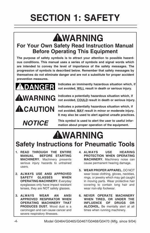
indicates a potentially hazardous situation which, if not avoided, may result in minor or moderate injury. it may also be used to alert against unsafe practices.
indicates a potentially hazardous situation which, if not avoided, could result in death or serious injury.
this symbol is used to alert the user to useful infor-mation about proper operation of the equipment.
safety instructions for pneumatic tools
for your own safety read instruction manual before operating this equipment
the purpose of safety symbols is to attract your attention to possible hazard-ous conditions. this manual uses a series of symbols and signal words which are intended to convey the level of importance of the safety messages. the progression of symbols is described below. remember that safety messages by themselves do not eliminate danger and are not a substitute for proper accident prevention measures.
1. read through the entire manual before starting machinery. machinery presents serious injury hazards to untrained users.
2. alWays use ansi approved safety glasses When operating machinery. Everyday eyeglasses only have impact resistant lenses, they are NOT safety glasses.
3. alWays Wear an ansi approved respirator When operating machinery that produces dust. Wood dust is a carcinogen and can cause cancer and severe respiratory illnesses.
NOTICE
4. alWays use hearing protection When operating machinery. machinery noise can cause permanent hearing damage.
5. Wear proper apparel. DO NOT wear loose clothing, gloves, neckties, rings, or jewelry which may get caught in moving parts. Wear protective hair covering to contain long hair and wear non-slip footwear.
6. never operate machinery When tired, or under the influence of drugs or alcohol. Be mentally alert at all times when running machinery.
indicates an imminently hazardous situation which, if not avoided, Will result in death or serious injury.
model G0464/G0465/G0467/G0468/G0470 (mfg. since 9/04) -5-
7. Keep children and visitors aWay. Keep all children and visitors a safe distance from the work area.
8. maKe WorKshop child proof. Use padlocks, master switches, and remove start switch keys. Shut off air supply before leaving shop.
9. never leave unattended tool connected to air. DO NOT leave before relieving the tool of air pressure and disconnecting it from the air hose.
10. do not use in dangerous environments. DO NOT use in damp, wet locations, or where flam-mable or noxious fumes may exist.
11. Keep WorK area clean and Well lit. Clutter and dark shad-ows may cause accidents.
12. use a grounded eXtension cord rated for the machine amperage. Undersized cords overheat and lose power. Replace extension cords if they become dam-aged. DO NOT use extension cords for 220V machinery.
13. only alloW trained and properly supervised per-sonnel to operate machin-ery. make sure operation instruc-tions are safe and understood.
14. maKe sure guards are in place and WorK correctly before using machinery.
15. checK for damaged parts before using machinery. Check for binding and alignment of parts, broken parts, part mounting, loose bolts, and any other conditions that may affect machine operation. Repair or replace damaged parts.
16. remove adJusting Keys and Wrenches. make a habit of check-ing for keys and adjusting wrenches before turning machinery ON.
17. reduce the risK of unintentional firing. DO NOT carry tool with hand on trigger and disconnect from air when not in use.
18. use proper air hose for the tool. make sure your air hose is in good condition and is long enough to reach your work without stretching.
19. do not force machinery. Work at the speed for which the machine or accessory was designed.
20. do not overreach. Keep prop-er footing and balance at all times.
21. secure WorKpiece. Use clamps or a vise to hold the workpiece when practical. A secured workpiece pro-tects your hands and frees both hands to operate the tool.
22. use suggested accessories. Refer to the instruction manual for recommended accessories. The use of improper accessories may cause risk of injury.
23. maintain machinery With care. Keep tools lubricated and clean for best and safest perfor-mance. Follow instructions for lubri-cating and changing accessories.
24. alWays disconnect from poWer source before servicing machinery. make sure switch is in OFF position before reconnecting.
25. disconnect pneumatic tools from compressor. Always dis-connect tools before servicing or changing accessories.
26. be aWare that certain Woods may cause allergic reactions in people and animals, especially When eXposed to fine dust. make sure you know what type of wood dust you will be exposed to and always wear an approved respirator.
model G0464/G0465/G0467/G0468/G0470 (mfg. since 9/04)-6-
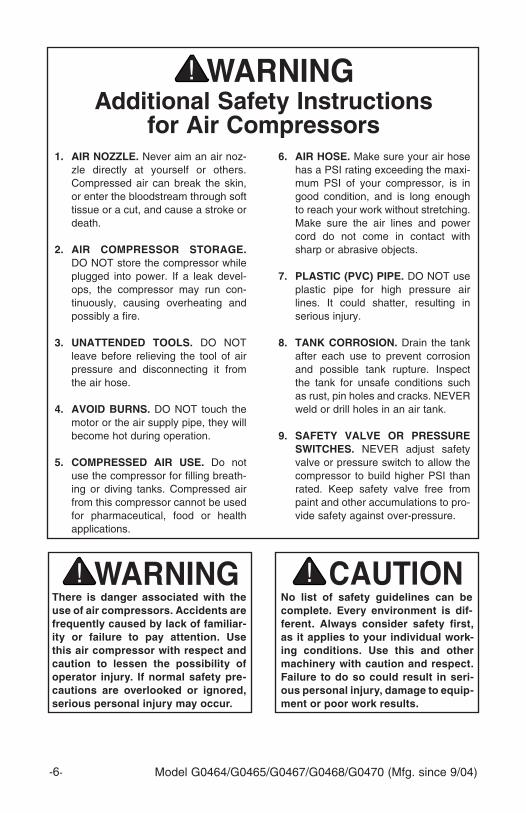
additional safety instructions for air compressors
no list of safety guidelines can be complete. every environment is dif-ferent. always consider safety first, as it applies to your individual work-ing conditions. use this and other machinery with caution and respect. failure to do so could result in seri-ous personal injury, damage to equip-ment or poor work results.
1. air nozzle. Never aim an air noz-zle directly at yourself or others. Compressed air can break the skin, or enter the bloodstream through soft tissue or a cut, and cause a stroke or death.
2. air compressor storage. DO NOT store the compressor while plugged into power. If a leak devel-ops, the compressor may run con-tinuously, causing overheating and possibly a fire.
3. unattended tools. DO NOT leave before relieving the tool of air pressure and disconnecting it from the air hose.
4. avoid burns. DO NOT touch the motor or the air supply pipe, they will become hot during operation.
5. compressed air use. Do not use the compressor for filling breath-ing or diving tanks. Compressed air from this compressor cannot be used for pharmaceutical, food or health applications.
6. air hose. make sure your air hose has a PSI rating exceeding the maxi-mum PSI of your compressor, is in good condition, and is long enough to reach your work without stretching. make sure the air lines and power cord do not come in contact with sharp or abrasive objects.
7. plastic (pvc) pipe. DO NOT use plastic pipe for high pressure air lines. It could shatter, resulting in serious injury.
8. tanK corrosion. Drain the tank after each use to prevent corrosion and possible tank rupture. Inspect the tank for unsafe conditions such as rust, pin holes and cracks. NEVER weld or drill holes in an air tank.
9. safety valve or pressure sWitches. NEVER adjust safety valve or pressure switch to allow the compressor to build higher PSI than rated. Keep safety valve free from paint and other accumulations to pro-vide safety against over-pressure.
there is danger associated with the use of air compressors. accidents are frequently caused by lack of familiar-ity or failure to pay attention. use this air compressor with respect and caution to lessen the possibility of operator injury. if normal safety pre-cautions are overlooked or ignored, serious personal injury may occur.
model G0464/G0465/G0467/G0468/G0470 (mfg. since 9/04) -7-
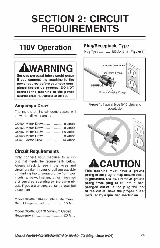
this machine must have a ground prong in the plug to help ensure that it is grounded. do not remove ground prong from plug to fit into a two-pronged outlet! if the plug will not fit the outlet, have the proper outlet installed by a qualified electrician.
section 2: circuit reQuirements
figure 1. Typical type 5-15 plug and receptacle.
5-15 PLUG
5-15 RECEPTACLE
serious personal injury could occur if you connect the machine to the power source before you have com-pleted the set up process. do not connect the machine to the power source until instructed to do so.
110v operation
amperage drawThe motors on the air compressors will draw the following amps:
G0464 motor Draw .......................8 AmpsG0465 motor Draw .......................8 AmpsG0467 motor Draw...................14.5 AmpsG0468 motor Draw .......................8 AmpsG0470 motor Draw ......................14 Amps
circuit requirementsOnly connect your machine to a cir-cuit that meets the requirements below. Always check to see if the wires and circuit breaker in your circuit are capable of handling the amperage draw from your machine, as well as any other machines that could be operating on the same cir-cuit. If you are unsure, consult a qualified electrician.
model G0464, G0465, G0468 minimum Circuit Requirement ......................15 Amp
model G0467, G0470 minimum Circuit Requirement ................................. 20 Amp
plug/receptacle typePlug Type ..............NEmA 5-15 (figure 1)
model G0464/G0465/G0467/G0468/G0470 (mfg. since 9/04)-8-
extension cordsThe use of extension cords can cause power loss and overheating in air com-pressors. When possible, locate the air compressor where it can be plugged into an outlet without the use of an extension cord, and use an additional air hose to reach the work area.
If you find it necessary to use an exten-sion cord with your machine:
• make sure the cord is rated Standard Service (grade S) or better.
• The extension cord must contain a ground wire and plug pin.
• Use at least a 14 gauge cord. Use a 12 gauge cord if the cord is between 25-100 feet.
• DO NOT use extension cords over 100 feet.
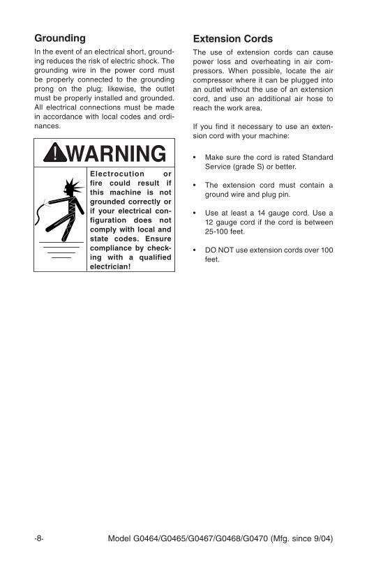
electrocution or fire could result if this machine is not grounded correctly or if your electrical con-figuration does not comply with local and state codes. ensure compliance by check-ing with a qualified electrician!
groundingIn the event of an electrical short, ground-ing reduces the risk of electric shock. The grounding wire in the power cord must be properly connected to the grounding prong on the plug; likewise, the outlet must be properly installed and grounded. All electrical connections must be made in accordance with local codes and ordi-nances.
model G0464/G0465/G0467/G0468/G0470 (mfg. since 9/04) -9-
unpacking
section 3: set up
Your air compressor left our warehouse in a carefully packed crate or box. If you dis-cover the air compressor is damaged after you have signed for delivery, please imme-diately call Customer Service at (570) 546-9663 for advice.
Save the container and packing materials for possible inspection by the carrier or its agent. Otherwise, filing a freight claim can be difficult.
assembly
to assemble the air compressor:
1. Remove all packing materials and any protective plastic bags, zip tie labels or tags from the compressor.
2. Be sure the air filter is attached to the cylinder head as shown in figure 2.
figure 3. Proper oil level.
3. Add compressor oil, or ISO 100/SAE 30W non-detergent oil, to the crank-case. Remove the oil breather (inset in figure 3) on top of the crankcase and add oil into the hole. The oil level should be in the center of the sight glass as shown in figure 3 (This step does not apply to the model G0468).
figure 2. Air filter attached to cylinder head.
Oil Breather
NOTICEnever run this compressor without a full oil reservoir. the oil provides lubrication to the cylinder rings, which deliver the compressed air. severe damage to the internal mov-ing parts can occur if there is not adequate oil flow. check the oil level frequently, and change the oil every 3 months.
NOTICEthe oil breather releases excess pressure from the crankcase. clogged holes in the oil breather can lead to damaged oil seals, gas-kets, and may cause the compres-sor to seize.
model G0464/G0465/G0467/G0468/G0470 (mfg. since 9/04)-10-
placement
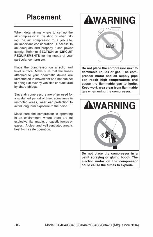
do not place the compressor next to flammable liquids or gas! the com-pressor motor and air supply pipe can reach high temperatures and cause the flammable gas to ignite. Keep work area clear from flammable gas when using the compressor.
When determining where to set up the air compressor in the shop or when tak-ing the air compressor to a job site, an important consideration is access to an adequate and properly fused power supply. Refer to section 2: circuit reQuirements for the needs of your particular compressor.
Place the compressor on a solid and level surface. make sure that the hoses attached to your pneumatic device are unrestricted in movement and not subject to being run over by vehicles or punctured by sharp objects.
Since air compressors are often used for a sustained period of time, sometimes in restricted areas, wear ear protection to avoid long term exposure to the noise.
make sure the compressor is operating in an environment where there are no explosive, flammable, or caustic fumes or gases. A clear and well ventilated area is best for its safe operation.
do not place the compressor in a paint spraying or gluing booth. the electric motor on the compressor could cause the fumes to explode.
model G0464/G0465/G0467/G0468/G0470 (mfg. since 9/04) -11-
operation safety
section 4: operations
long term exposure to this machine may cause hearing loss. to protect your hearing, always wear ansi approved ear protection when operat-ing this air compressor.
operating this equipment has the potential for flying debris to cause eye injury. always wear safety glass-es or goggles when operating equip-ment. everyday glasses or reading glasses only have impact resistant lenses, they are not safety glasses. be certain the safety glasses you wear meet the appropriate standards of the american national standards institute (ansi).
starting
to start the air compressor:
1. Place the compressor on a solid, level surface with access to a properly fused power supply. DO NOT oper-ate the compressor in an environment where there are explosive, flammable, or caustic fumes or gases.
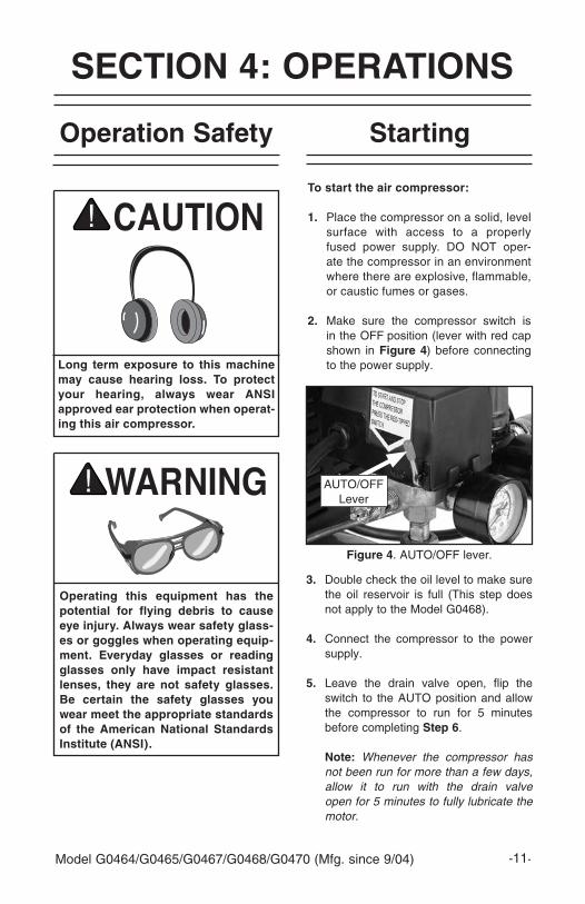
2. make sure the compressor switch is in the OFF position (lever with red cap shown in figure 4) before connecting to the power supply.
figure 4. AUTO/OFF lever.
3. Double check the oil level to make sure the oil reservoir is full (This step does not apply to the model G0468).
4. Connect the compressor to the power supply.
5. Leave the drain valve open, flip the switch to the AUTO position and allow the compressor to run for 5 minutes before completing step 6.
note: Whenever the compressor has not been run for more than a few days, allow it to run with the drain valve open for 5 minutes to fully lubricate the motor.
AUTO/OFF Lever
model G0464/G0465/G0467/G0468/G0470 (mfg. since 9/04)-12-
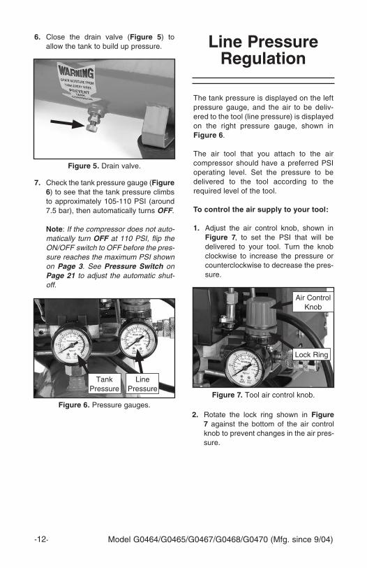
6. Close the drain valve (figure 5) to allow the tank to build up pressure.
7. Check the tank pressure gauge (figure 6) to see that the tank pressure climbs to approximately 105-110 PSI (around 7.5 bar), then automatically turns OFF.
note: If the compressor does not auto-matically turn OFF at 110 PSI, flip the ON/OFF switch to OFF before the pres-sure reaches the maximum PSI shown on Page 3. See Pressure Switch on Page 21 to adjust the automatic shut-off.
figure 5. Drain valve.
figure 7. Tool air control knob.
The tank pressure is displayed on the left pressure gauge, and the air to be deliv-ered to the tool (line pressure) is displayed on the right pressure gauge, shown in figure 6.
The air tool that you attach to the air compressor should have a preferred PSI operating level. Set the pressure to be delivered to the tool according to the required level of the tool.
to control the air supply to your tool:
1. Adjust the air control knob, shown in figure 7, to set the PSI that will be delivered to your tool. Turn the knob clockwise to increase the pressure or counterclockwise to decrease the pres-sure.
line pressure regulation
Air Control Knob
Lock Ring
2. Rotate the lock ring shown in figure 7 against the bottom of the air control knob to prevent changes in the air pres-sure.
figure 6. Pressure gauges.
Tank Pressure
Line Pressure
model G0464/G0465/G0467/G0468/G0470 (mfg. since 9/04) -13-
When choosing air tools, consider the amount of air used (cubic feet per min-ute or CFm) by the tool. Nailers and staple guns have a low CFm requirement because they use air in short bursts. A paint sprayer or a pneumatic grinder uses a more continuous stream of air requir-ing a high CFm. make sure the air tool you plan to connect does not exceed the CFm output of your compressor. most air tools will have an air requirement stated in terms of a specific CFm at a specific pressure.
Air tools being operated with insufficient air volume will not perform their function satisfactorily and they will cause the air compressor to run continually. When an air compressor runs continually it may overheat, causing damage to the com-pressor and the possibility of a fire. This compressor is fitted with thermal protec-tion inside the motor. If the compressor overheats, the motor will automatically turn OFF until it cools down.
to connect air tools to your air com-pressor:
1. Follow the compressor starting instruc-tions on page 11.
2. Connect the tool to a good quality air hose that is long enough to reach from the point of use to the compressor.
note: Be aware of the placement of the hose to prevent damage. Make certain the air hose is not located where it can become constricted, cut by a sharp object, or run over. Running over a hose with a vehicle may not cause an immediate leak, but it will shorten the life of the hose.
connecting tools
these air compressors are specifi-cally designed for air tool operation. do not modify or use this machine for any other purpose. modifications or improper use of this tool will void the warranty. if you are confused about any aspect of this machine, do not use it until your questions have been answered. serious per-sonal injury may occur.
figure 8. Quick connect coupler.
3. Connect an air line with a 1⁄4" NPT plug to the quick-connect coupler on the air compressor shown in figure 8.
note: There are many styles of 1⁄4" NPT quick connect couplers. If the quick connect coupler included with the com-pressor does not fit the plug on your air hose, purchase a matched set at your local hardware store.
model G0464/G0465/G0467/G0468/G0470 (mfg. since 9/04)-14-
always disconnect the air hose from tools whenever not in use or while servicing! during maintenance, a tool connected to air may operate accidentally, causing serious per-sonal injury!
When storing your air compressor, fol-low these guidelines:
1. Turn the compressor switch lever to OFF.
2. Unplug the compressor.
3. Turn the regulator counterclockwise to set the line pressure to zero.
4. Run the air tool to relieve the air pres-sure in the hose, then remove the air hose and the tool.
5. Drain water from the tank as instructed in draining tank on page 16. Leave the valve open until the next usage.
note: Draining the air from the tank will be extremely loud. Wear ear protection when draining the tank.
6. Store the air compressor in its normal operating position in a cool protected area.
storage
Water will condense in the air com-pressor tank. Water left in the tank can cause the tank to weaken and corrode, increasing the risk of tank rupture.
failure to unplug the air compres-sor before storage may result in the compressor running continuously, causing overheating, damage to the compressor, and possibly a fire.
model G0464/G0465/G0467/G0468/G0470 (mfg. since 9/04) -15-
section 5: maintenance
schedule
For optimum performance from your machine, follow this maintenance sched-ule and refer to any specific instructions given in this section.
daily1. Check the oil level! Use the sight glass
on the crankcase to make sure the oil reservoir is at the correct level.
2. Check for worn or damaged cords and plugs.
3. Check for any other condition that could hamper the safe operation of this air compressor.
4. When finished using the air compres-sor, drain the condensation from the tank as instructed in draining tank on page 16, and leave the drain valve open until the next use.
the air compressor will turn ON automatically when it is set on auto. When performing maintenance make sure the auto/off lever is in the off position, the compressor is unplugged, and the air pressure has been bled out of the tank.
operating this equipment has the potential to cause eye injury and hearing loss. always wear eye and ear protection when operating an air compressor. be certain the safety protection you wear meet the appro-priate standards of the american national standards institute (ansi).
If the compressor is used on a daily basis, perform the following checks each week.
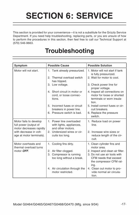
Weekly1. Blow dirt and dust off of the air filter
(figure 9), then re-install.
2. Check for loose bolts or fittings.
3. Clean off all dirt and dust from the cylin-der head, motor, fan, air lines, exhaust pipe, couplers and frame. Dirt can lead to overheating.
4. Check air lines and connectors to make sure they are in good condition.
5. Pull the safety drain valve to make sure it is working properly (see draining tank on page 16).
figure 9. Air filter foam element.
model G0464/G0465/G0467/G0468/G0470 (mfg. since 9/04)-16-
monthlyAfter the first 50 working hours or 30 days, perform the following maintenance:
1. Change the oil in the air compressor pump as described in changing oil on page 19.
QuarterlyAfter every 300 working hours or 3 months, perform the following maintenance:
1. Change the oil in the air compressor pump as described in changing oil on page 19.
2. Check for air leaks and correct as needed.
figure 11. Pressure safety valve.
2. Clean any dirt or dust from the pres-sure safety valve.
3. Pull the metal ring on top of the safety valve to ensure the valve will release air. The pressure safety valve must be replaced if it cannot be pulled, or if it leaks after releasing pressure.
note: The safety valve is preset to release air if the tank exceeds its maxi-mum pressure. DO NOT try to adjust the safety valve pressure setting!
Some water may accumulate in the tank depending on usage and humidity. Drain water from the tank daily to increase the lifespan of the compressor and air tools.
to drain the tank:
1. Leave the tank pressurized and open the drain valve, shown in figure 10, to drain the water out of the tank.
note: Draining the air from the tank will
be extremely loud. Wear ear protection when draining the tank.
draining tank
The pressure safety valve prevents dam-age to the tank by releasing pressure when the tank reaches maximum capacity.
to check the pressure safety valve:
1. Locate the pressure safety valve shown in figure 11.
figure 10. Tank drain valve.
pressure safety valve
releasing the safety valve can be extremely loud. protect your hearing with ansi approved ear protection.
Pressure Safety Valve
model G0464/G0465/G0467/G0468/G0470 (mfg. since 9/04) -17-
section 6: service
This section is provided for your convenience—it is not a substitute for the Grizzly Service Department. If you need help troubleshooting, replacing parts, or you are unsure of how to perform the procedures in this section, then feel free to call our Technical Support at (570) 546-9663.
symptom possible cause possible solution
motor will not start. 1. Tank already pressurized.
2. Thermal overload switch has tripped.
3. Low voltage.
4. Short circuit in motor or cord, or loose connec-tions.
5. Incorrect fuses or circuit breakers in power line.
6. Pressure switch is bad.
1. motor will not start if tank is fully pressurized.
2. Wait for motor to cool.
3. Check power line for proper voltage.
4. Inspect all connections on motor for loose or shorted terminals or worn insula-tion.
5. Install correct fuses or cir-cuit breakers.
6. Replace the pressure switch.
motor fails to develop full power (output of motor decreases rapidly with decrease in volt-age at motor terminals).
1. Power line overloaded with lights, appliances, and other motors.
2. Undersized wires or cir-cuits too long.
1. Reduce load on power line.
2. Increase wire sizes or reduce length of the cir-cuit.
motor overheats and thermal overload turns motor OFF.
1. Cooling fins dirty.
2. Air filter clogged.3. Compressor is running
too long without a break.
4. Air circulation through the motor restricted.
1. Clean cylinder fins and motor area.
2. Inspect and clean air filter.3. Do not use air tools with
CFm needs that exceed the compressor CFm rat-ing.
4. Clean out motor to pro-vide normal air circula-tion.
troubleshooting
model G0464/G0465/G0467/G0468/G0470 (mfg. since 9/04)-18-
symptom possible cause possible solution
Loud repetitious noise coming from air com-pressor.
1. Pulley setscrews or keys are missing or loose.
2. motor fan is hitting the cover.
1. Inspect keys and set-screws. Replace or tighten if necessary.
2. Adjust fan cover mounting position, tighten fan, or shim fan cover.
Low pressure at the tool.
1. Pressure regulator.
2. Air leaks in hoses.
3. Pressure gauge bad.
4. Pressure switch turns the motor OFF too soon.
1. Adjust pressure regulator, if no improvement, inspect regulator for leaks or replace.
2. Check air hoses and all connections for leaks (see page 20).
3. Replace the pressure gauge.
4. Adjust the pressure switch (see page 21).
Low pressure at the tanks, or tank pressure drops after compressor is turned OFF.
1. Air leaks in tanks or deliv-ery pipes.
2. Drain valve open.3. Air filter clogged.4. Leaking check valve.
5. Pressure relief valve releasing below 110 PSI.
6. Gaskets leaking.
7. Worn rings.
8. Pressure switch turns the motor OFF too soon.
1. Check air tanks, pipes and all connections for leaks (see page 20).
2. Close drain valve.3. Inspect and clean air filter.4. Repair the check valve
(see page 19).5. Replace pressure relief
valve.6. Check gaskets on cylinder
head assembly, repair or replace as needed.
7. Inspect and replace pump piston rings.
8. Adjust the pressure switch (see page 21).
Compressor knocking. 1. Improper oil level.
2. Air filter clogged.3. Piston assembly loose.
1. Check oil level and add oil (see page 9).
2. Inspect and clean air filter.3. Inspect and repair piston
and connecting rod.
Pressure relief valve stays open and motor won’t stop running.
1. Pressure switch adjusted too high.
2. Faulty pressure switch, unit is trying to overpres-sure the tank.
3. Faulty pressure relief valve.
1. Adjust the pressure switch (see page 21)
2. Turn compressor OFF, unplug from power sup-ply, and empty tank. DO NOT USE until switch is replaced.
3. Relief valve is reliev-ing pressure too early. Replace pressure relief valve.
model G0464/G0465/G0467/G0468/G0470 (mfg. since 9/04) -19-
figure 12. Oil sight glass.
5. Replace the oil sight glass and remove the fill plug shown in figure 12.
6. Fill the crank case with oil until the oil level is in the center of the sight glass, then replace the oil fill plug.
Oil Fill Plug
Oil Sight Glass
symptom possible cause possible solution
Air leaks from pressure switch.
1. Faulty check valve.
2. Faulty pressure switch.
1. Repair the check valve (see page 19).
2. Replace pressure switch.
Air is dirty or has exces-sive moisture.
1. Tank is not drained.
2. Delivery pipes are dirty.
1. Open drain valve and make certain all the water is drained out.
2. Remove delivery pipes, clean out and replace.
changing oil
Change the oil in the air compressor pump after the initial 50 hours, or 30 days of use; and every 300 hours, or 3 months after the first oil change. Use compressor oil or ISO 100/SAE 30W, non-detergent type oil.
to change the oil:
1. unplug the air compressor and drain all the air from the tank.
2. Place a container to catch the oil under the oil sight glass.
3. Use a box end wrench or a socket wrench to remove the oil sight glass shown in figure 12.
check valve
The diaphragm and O-ring in the check valve can become damaged, twisted, or dirty and cause the check valve or pres-sure switch to leak air.
to fix the check valve:
1. unplug the air compressor and drain all the air from the tank.
2. Remove the cap from the check valve (see figure 13).
figure 13. Check valve.4. Tip the compressor to drain all of the oil from the crank case.
Cap
model G0464/G0465/G0467/G0468/G0470 (mfg. since 9/04)-20-
fixing air leaks
Air leaks will cause low air output and increase the time the compressor must run.
to find air leaks:
1. Turn the compressor OFF when the tank is fully pressurized and unplug the compressor.
2. Listen for the sound of air to find fittings that may be leaking.
3. Spray the suspected air leak with a soap and water solution. If you see air bubbles, you have found your leak.
to fix air leaking around fitting threads:
1. unplug the air compressor and drain all the air from the tank.
2. Unscrew the fitting that is leaking. Clean and wrap teflon tape and/or spread pipe dope on the threads.
3. Re-install the fitting to the compressor.
to fix air leaking through a valve:
1. unplug the air compressor and drain all the air from the tank.
2. Remove the valve, clean it thoroughly, then re-install with teflon tape and/or pipe dope.
3. If the valve continues to leak, replace it with a new valve.
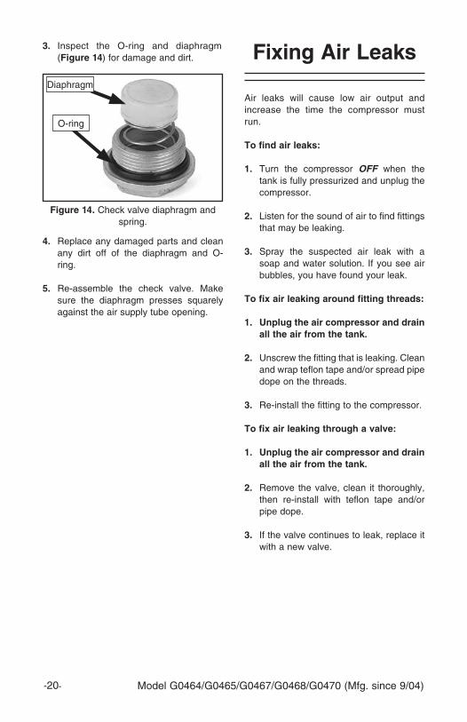
figure 14. Check valve diaphragm and spring.
Diaphragm
O-ring
3. Inspect the O-ring and diaphragm (figure 14) for damage and dirt.
4. Replace any damaged parts and clean any dirt off of the diaphragm and O-ring.
5. Re-assemble the check valve. make sure the diaphragm presses squarely against the air supply tube opening.
model G0464/G0465/G0467/G0468/G0470 (mfg. since 9/04) -21-
The pressure switch has been factory set for the highest PSI that is safe for this compressor.
The pressure switch ensures the com-pressor will shut OFF when the air tank reaches maximum PSI.
pressure switch
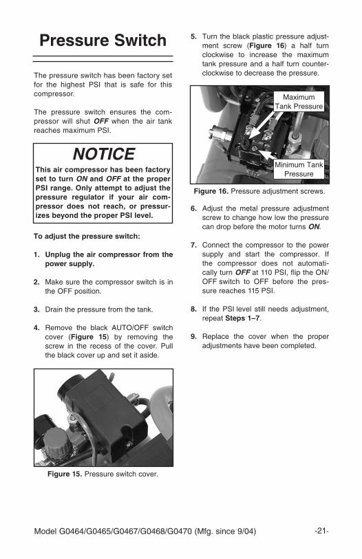
figure 16. Pressure adjustment screws.
5. Turn the black plastic pressure adjust-ment screw (figure 16) a half turn clockwise to increase the maximum tank pressure and a half turn counter-clockwise to decrease the pressure.
NOTICE this air compressor has been factory set to turn ON and OFF at the proper psi range. only attempt to adjust the pressure regulator if your air com-pressor does not reach, or pressur-izes beyond the proper psi level.
to adjust the pressure switch:
1. unplug the air compressor from the power supply.
2. make sure the compressor switch is in the OFF position.
3. Drain the pressure from the tank.
4. Remove the black AUTO/OFF switch cover (figure 15) by removing the screw in the recess of the cover. Pull the black cover up and set it aside.
figure 15. Pressure switch cover.
6. Adjust the metal pressure adjustment screw to change how low the pressure can drop before the motor turns ON.
7. Connect the compressor to the power supply and start the compressor. If the compressor does not automati-cally turn OFF at 110 PSI, flip the ON/OFF switch to OFF before the pres-sure reaches 115 PSI.
8. If the PSI level still needs adjustment, repeat steps 1 –7.
9. Replace the cover when the proper adjustments have been completed.
maximum Tank Pressure
minimum Tank Pressure
model G0464/G0465/G0467/G0468/G0470 (mfg. since 9/04)-22-
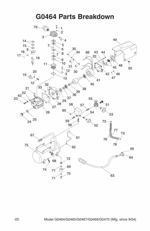
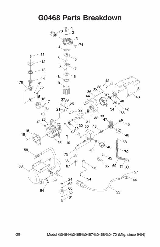
g0464 parts breakdown
model G0464/G0465/G0467/G0468/G0470 (mfg. since 9/04) -23-
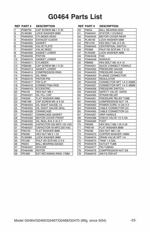
g0464 parts listREF PART # DESCRIPTION REF PART # DESCRIPTION1 PSB07M CAP SCREW M6-1 X 30 40 P6004 BALL BEARING 60042 PLW03M LOCK WASHER 6MM 41 P0464041 STATOR 115V/60HZ3 P0464003 CYLINDER HEAD 42 P0464042 MOTOR COVER REAR4 P0464004 EXHAUST ELBOW 43 PLW01M LOCK WASHER 5MM5 P0464005 GASKET 44 PB151M HEX BOLT M5-.8 X 356 P0464006 VALVE PLATE 45 P0464045 CENTRIFIGAL SWITCH7 P0464007 VALVE REED 46 PS38M PHLP HD SCR M4-.7 X 108 P0464008 GASKET LOWER 47 PLW02M LOCK WASHER 4MM9 P0464009 PISTON 48 P0464048 FAN10 P0464010 GASKET LOWER 49 P0464049 SHROUD11 P0464011 CYLINDER 50 PB96M HEX BOLT M5-.8 X 1012 PSB02M CAP SCREW M6-1 X 20 51 P0464051 QUICK CONNECT-FEMALE13 P0464013 GASKET LOWER 52 P0464052 PRESSURE GAUGE14 P0464014 COMPRESSION RING 53 P0464053 PRESSURE GAUGE15 P0464015 OIL RING 54 P0464054 FLANGE CONNECTOR16 P0464016 PISTON PIN 55 P0464055 REGULATOR17 P0464017 PIN CLIP 56 P0464056 CONNECTOR NPT 1/4 X 40MM18 P0464018 CONNECTING ROD 57 P0464057 CONNECTOR NPT 1/4 X 48MM19 P0464019 ECCENTRIC 58 P0464058 PRESSURE SWITCH20 PN01M HEX NUT M6-1 59 P0464059 SAFETY VALVE 140PSI21 P0464021 OIL FILL CAP 60 P0464060 STRAIN RELIEF22 PW02M FLAT WASHER 5MM 61 P0464061 PRESSURE RELIEF TUBE23 PSB15M CAP SCREW M5-.8 X 20 62 P0464062 COMPRESSION NUT 1/824 P0464024 OIL SIGHT GAUGE 1/2 63 P0464063 POWER CORD 14 GA X 225 P0464025 OIL SIGHT GAUGE SEAL 64 P0464064 CABLE CONNECTOR (O)26 P0464026 CRANKCASE 65 P0464065 CABLE CONNECTOR (U)27 P0464027 CRANKCASE GASKET 67 P0464067 GRIP HANDLE28 P0464028 MOTOR COVER FRONT 68 P0464068 CHECK VALVE 1/2 X 3/829 P0464029 OIL SEAL B16 X 35 X 7 69 P0464069 FOOT30 P0464030 CAPACITOR 200 MFD 125 VAC 70 PB09M HEX BOLT M8-1.25 X 2031 P0464031 CAPACITOR 40 MFD 250 VAC 71 PW01M FLAT WASHER 8MM32 PW01M FLAT WASHER 8MM 72 PN03M HEX NUT M8-1.2533 PN03M HEX NUT M8 X 1.25 73 P0464073 COPPER WASHER 10MM34 PLW09M LOCK WASHER 3MM 74 P0464074 DRAIN VALVE NPT 1/435 PS12M PHLP HD SCR M3-.5 X 6 75 P0464075 TANK 1.5 GAL36 P6203 BALL BEARING 6203ZZ 76 P0464076 OUTLET TUBE37 P0464037 SPACER 77 P0464077 FIN TUBING38 P0464038 ROTOR 78 P0464078 COMPRESSION NUT 3/839 PR18M EXT RETAINING RING 17MM 79 P0464079 AIR FILTER KIT
model G0464/G0465/G0467/G0468/G0470 (mfg. since 9/04)-24-
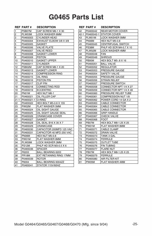
g0465 parts breakdown
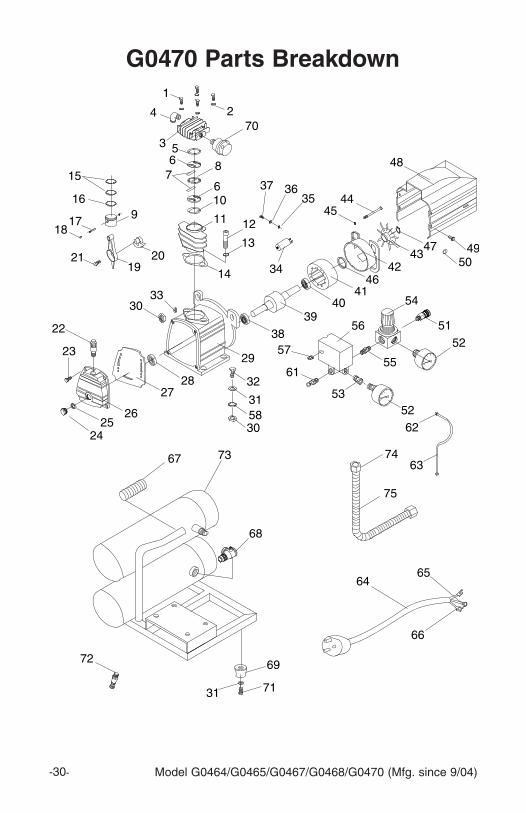
model G0464/G0465/G0467/G0468/G0470 (mfg. since 9/04) -25-
Grizzly Industrial, Inc. warrants every product it sells for a period of 1 year to the original purchaser from the date of purchase. This warranty does not apply to defects due directly or indirectly to misuse, abuse, negligence, accidents, repairs or alterations or lack of maintenance. This is Grizzly’s sole written warranty and any and all warranties that may be implied by law, including any merchantability or fitness, for any particular purpose, are hereby limited to the duration of this written warranty. We do not warrant or represent that the merchandise complies with the provisions of any law or acts unless the manufacturer so warrants. In no event shall Grizzly’s liability under this warranty exceed the purchase price paid for the product and any legal actions brought against Grizzly shall be tried in the State of Washington, County of Whatcom.
We shall in no event be liable for death, injuries to persons or property or for incidental, contingent, special, or consequential damages arising from the use of our products.
To take advantage of this warranty, contact us by mail or phone and give us all the details. We will then issue you a “Return Authorization Number,” which must be clearly posted on the outside as well as the inside of the carton. We will not accept any item back without this number. Proof of purchase must accompany the merchandise.
The manufacturers reserve the right to change specifications at any time because they constantly strive to achieve better quality equipment. We make every effort to ensure that our products meet high quality and durability standards and we hope you never need to use this warranty.
Please feel free to write or call us if you have any questions about the machine or the manual.
model # ____________________ Order # _______________________ Serial # ______
The following information is given on a voluntary basis. It will be used for marketing purposes to help us develop better products and services. All information is strictly confidential.
1. How did you learn about us? ____Advertisement ____Friend ____Catalog ____Card Deck ____Website Other:________________________
2. Which of the following magazines do you subscribe to?
3. What is your annual household income? ____$20,000-$29,000 ____$30,000-$39,000 ____$40,000-$49,000 ____$50,000-$59,000 ____$60,000-$69,000 ____$70,000+
4. What is your age group? ____20-29 ____30-39 ____40-49 ____50-59 ____60-69 ____70+
5. How long have you been a woodworker/metalworker? ____0-2 Years ____2-8 Years ____8-20 Years ____20+ Years
6. How many of your machines or tools are Grizzly? ____0-2 ____3-5 ____6-9 ____10+
7. Do you think your machine represents a good value? ____Yes ____No
8. Would you recommend Grizzly Industrial to a friend? ____Yes ____No
9. Would you allow us to use your name as a reference for our customers in your area? Note: We never use names more than 3 times. ____Yes ____No
____ Cabinet maker____ Family Handyman____ Hand Loader____ Handy____ Home Shop machinist____ Journal of Light Cont.____ Live Steam____ model Airplane News____ modeltec____ Old House Journal
____ Popular mechanics____ Popular Science____ Popular Woodworking____ Practical Homeowner____ Precision Shooter____ Projects in metal____ RC modeler____ Rifle____ Shop Notes____ Shotgun News