This Air Conditioner is a new type which adopts a new refrigerant HFC (R410A) instead of the conventionalrefrigerant R22 in order to prevent destruction of the ozone layer.
WARNING
Cleaning of the air filter and other parts of the air filter involves dangerous work in high places, so be sure tohave a service person do it. Do not attempt it yourself.The cleaning diagram for the air filter is there for the service person, and not for the customer.
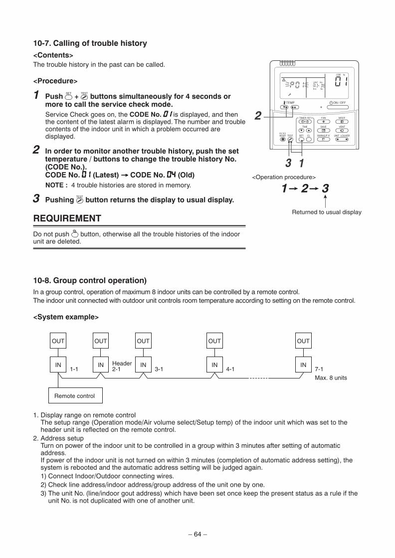
10. SETUP AT LOCAL SITE AND OTHERS ................................... 5810-1. Test Run Setup on Remote Control ................................................................................ 5810-2. Forced Defrost Setup of Remote Control (For wired remote control only) ................ 5910-3. LED Display on P.C. Board .............................................................................................. 5910-4. Function Selection Setup ................................................................................................ 6010-5. Wiring and Setting of Remote Control Control ............................................................. 6210-6. Monitor Function of Remote Control Switch ................................................................. 6310-7. Calling of trouble history ................................................................................................. 6410-8. Group control operation) ................................................................................................. 64
– 3 –
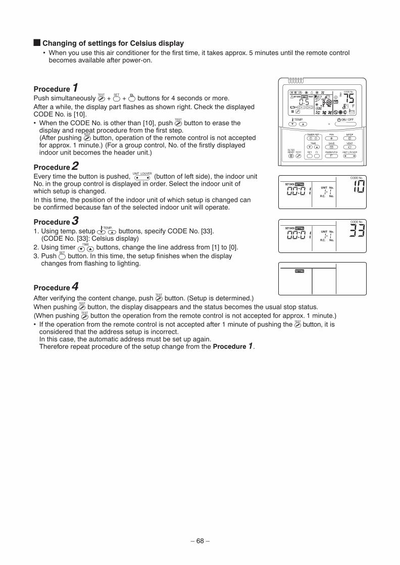
11. ADDRESS SETUP ..................................................................... 6611-1. Address Setup Procedure ............................................................................................... 6611-2. Address Setup & Group Control ..................................................................................... 6711-3. Remote Control Wiring .................................................................................................... 6911-4. Address Setup (Manual setting from remote control) .................................................. 7011-5. Confirmation of Indoor Unit No. Position ...................................................................... 71
13. REPLACEMENT OF SERVICE P.C. BOARD............................. 80
14. EXPLODED VIEWS AND PARTS LIST ..................................... 85
– 4 –
Indication
DANGER
WARNING
CAUTION
Explanation
Indicates that an imminent danger causing a death or serious injury of the repair engineers and the third parties may occur when an incorrect work has been executed.
Indicates possibilities of a danger causing death or serious injury of the repair engineers, the third parties, and the users due to problems from the product after installation when an incorrect work has been executed.
Indicates that an injury or property damage (∗) may be caused to the repair engineers, the third parties involved, and the users due to troubles of the product after installation when an incorrect work has been executed.
Mark Explanation
Indicates prohibited items (Forbidden to do)
The sentences near an illustrated mark describe the concrete prohibited contents.
Indicates mandatory items (Compulsory to do)
The sentences near an illustrated mark describe the concrete mandatory contents.
Indicates cautions (Including danger/warning)
The sentences or illustration near or in an illustrated mark describe the concrete cautious contents.
Turn off breaker.
Execute dischargebetween terminals.
Prohibition
Turn “OFF” the breaker before removing the front panel and cabinet, otherwise an electricshock is caused by high voltage which may result in death or injury.
During operation, a high voltage with 400V or higher of circuit (∗) at secondary circuit of thehigh-voltage transformer is applied.
If touching a high voltage with the naked hands or body, an electric shock is caused even if using anelectric insulator.
∗ : For details, refer to the electric wiring diagram.
When removing the front panel or cabinet, execute short-circuit and discharge betweenhigh-voltage capacitor terminals.
If discharge is not executed, an electric shock is caused by high voltage which could result in deathor injury.After turning off the breaker, high voltage is kept on the high-voltage capacitor.
Do not turn on the breaker under condition that the front panel and cabinet are removed.
An electric shock is caused by high voltage which could result in death or injury.
DANGER
SAFETY CAUTIONThe important contents concerned to the safety are described on the product itself and on this Service Manual.Please read this Service Manual and understand the described items thoroughly in the following contents(Indications/Illustrated marks), and keep the manual for reference. The manufacturer shall not assume anyliability for the damage caused by not observing the description of this manual.
[Explanation of indications]
∗ Property damage : Enlarged damage concerned with property, furniture, and domestic animal/pet
[Explanation of illustrated marks]
[Confirmation of warning label on the main unit]Confirm that labels are indicated on the specified positions(Refer to the Parts disassembly diagram (Outdoor unit).)If removing the label when parts are being replaced, stick it back on the original location.
– 5 –
Check ground wires.
Prohibition of modification.
Use specified parts.
Do not bring a childclose to the equipment.
Insulating measures
No fire
Refrigerant
Assembly/Cabling
Before troubleshooting or repair work, check the ground wire is connected to the groundterminals of the main unit, otherwise an electric shock is caused when a leak occurs.
If the ground wire is not correctly connected, contact an electrician for rework.
Do not modify the products.
Do not also disassemble or modify the parts. It may cause a fire, electric shock or injury.
For spare parts, use those specified (∗).
If unspecified parts are used, a fire or electric shock may be caused.
∗: For details, refer to the parts list.
Before troubleshooting or repair work, do not bring a third party (a child, etc.) exceptthe repair engineers close to the equipment.
It causes an injury with tools or disassembled parts.Please inform the users so that the third party (a child, etc.) does not approach the equipment.
Connect the cut-off lead wires with crimp contact, etc, put the closed end side upwardand then apply a water-cut method, otherwise a leak or fire is caused at the users’ side.
When repairing the refrigeration cycle, take the following measures.
1) Be attentive to fire around the cycle. When using a gas stove, etc, be sure to put out firebefore work; otherwise the oil mixed with refrigerant gas may catch fire.
2) Do not use a welder in the closed room.When using it without ventilation, carbon monoxide poisoning may be caused.
3) Do not bring inflammables close to the refrigerant cycle, otherwise fire of the welder maycatch the inflammables.
Check the used refrigerant name and use tools and materials of the parts which match with it.
For the products which use R410A refrigerant, the refrigerant name is indicated at a positionon the outdoor unit where is easy to see. To prevent miss-charging, the route of the serviceport is changed from one of the former R22.
Do not use any refrigerant different from the one specified for complement or replacement.
Otherwise, abnormally high pressure may be generated in the refrigeration cycle, which mayresult in a failure or explosion of the product or an injury to your body.
For an air conditioner which uses R410A, never use other refrigerant than R410A.For an air conditioner which uses other refrigerant (R22, etc.), never use R410A.
If different types of refrigerant are mixed, abnormal high pressure generates in therefrigeration cycle and an injury due to breakage may be caused.
Do not charge additional refrigerant.
If charging additional refrigerant when refrigerant gas leaks, the refrigerant composition inthe refrigerating cycle changes results in change of air conditioner characteristics orrefrigerant over the specified standard amount is charged and an abnormal high pressure isapplied to the inside of the refrigerating cycle resulted in cause of breakage or injury. Thereforeif the refrigerant gas leaks, recover the refrigerant in the air conditioner, execute vacuuming,and then newly recharge the specified amount of liquid refrigerant.In this time, never charge the refrigerant over the specified amount.
When recharging the refrigerant in the refrigerating cycle, do not mix the refrigerant orair other than R410A into the specified refrigerant.
If air or others is mixed with the refrigerant, abnormal high pressure generates in therefrigerating cycle resulted in cause of injury due to breakage.
After installation work, check the refrigerant gas does not leak.
If the refrigerant gas leaks in the room, poisonous gas generates when gas touches fire such as fan heater, stove or cocking stove though the refrigerant gas itself is innocuous.
Never recover the refrigerant into the outdoor unit.
When the equipment is moved or repaired, be sure to recover the refrigerant with recoveringdevice. The refrigerant cannot be recovered in the outdoor unit; otherwise a serious accidentsuch as breakage or injury is caused.
After repair work, assemble the disassembled parts, and connect and lead the removed wires as before. Perform the work so that the cabinet or panel does not catch the inner wires.
If incorrect assembly or incorrect wire connection was done, a disaster such as a leak or fire iscaused at user’s side.
WARNING
– 6 –
After the work has finished, be sure to use an insulation tester set (500V Megger) tocheck the resistance is 2MΩ or more between the charge section and the non-chargemetal section (Ground position).
If the resistance value is low, a disaster such as a leak or electric shock is caused at user’sside.
When the refrigerant gas leaks during work, execute ventilation.
If the refrigerant gas touches a fire, poisonous gas generates.A case of leakage of the refrigerant and the closed room full with gas is dangerous becausea shortage of oxygen occurs. Be sure to execute ventilation.
When checking the circuit with the power-ON, use rubber gloves and do not touch the charging section.
If touching to the charging section, an electric shock may be caused.
When you access inside of the service panel to repair electric parts, wait for aboutfive minutes after turning off the breaker. Do not start repairing immediately.Otherwise you may get electric shock by touching terminals of high-voltage capacitors.Natural discharge of the capacitor takes about five minutes.
When the refrigerant gas leaks, find the leaked position and repair it.
If the leaked position cannot be found and the repair work is interrupted, pump-downand tighten the service valve, otherwise the refrigerant gas may leak into the room.The poisonous gas generates when gas touches fire such as fan heater, stove or cockingstove though the refrigerant gas itself is innocuous.
When installing equipment which includes a large amount of charged refrigerantsuch as a multi air conditioner in a sub-room, it is necessary that the density doesnot the limit even if the refrigerant leaks.
If the refrigerant leaks and exceeds the limit density, an accident of shortage of oxygen iscaused.
For the installation/moving/reinstallation work, follow to the Installation Manual.
If an incorrect installation is done, a trouble on the refrigerating cycle, water leak, electricshock or fire is caused.
After repair work has been finished, check there is no trouble.
If check is not executed, a fire, electric shock or injury may be caused.For a check, turn off the power breaker.
After repair work (installation of front panel and cabinet) has finished, execute a testrun to check there is no generation of smoke or abnormal sound.
If check is not executed, a fire or an electric shock is caused.Before test run, install the front panel and cabinet.
Check the following items after reinstallation.
1) The ground wire is correctly connected.
2) The power cord is not caught in the product.
3) There is no inclination or unsteadiness and the installation is stable.
Insulator check
Ventilation
Be attentive toelectric shock
Compulsion
Check after repair
Check after reinstallation
WARNING
CAUTION
Put on gloves
Cooling check
Be sure to put on the gloves (∗) and a long sleeved shirt:otherwise an injury may be caused with the parts, etc.
(∗) Heavy gloves such as work gloves
When the power is turned on, start to work after the equipment has been sufficiently cooled.
As temperature of the compressor pipes and others became high due to cooling/heatingoperation, a burn may be caused.
– 7 –
• Refrigerant (R410A)This air conditioner adopts a HFC type refrigerant (R410A) which does not deplete the ozone layer.
1. Safety Caution Concerned to Refrigerant (R410A)The pressure of R410A is high 1.6 times of that of the previous refrigerant (R22).Accompanied with change of refrigerant, the refrigerating oil has been also changed.Therefore, be sure that water, dust, the previous refrigerant or the previous refrigerating oil is not mixed intothe refrigerating cycle of the air conditioner with refrigerant (R410A) installation work or service work.If an incorrect work or incorrect service is performed, there is a possibility of a serious accident.Use the tools and materials exclusive to R410A to ensure a safe work.
2. Cautions on Installation/Service1) Do not mix other refrigerant or refrigerating oil.
For the tools exclusive to R410A, shapes of all the joints including the service port differ from those of theprevious refrigerant in order to prevent mixture of them.
2) As the use pressure of the refrigerant (R410A) is high, use material thickness of the pipe and tools whichare specified for R410A.
3) In the installation time, use clean pipe materials and work with great attention so that water and others donot mix in because pipes are affected by impurities such as water, oxide scales, oil, etc.Use clean pipes.Be sure to braze with flowing nitrogen gas. (Never use any other gas except for nitrogen.)
4) For the ground protection, use a vacuum pump for air purge.5) R410A refrigerant is azeotropic mixture type refrigerant.
Therefore use liquid type to charge the refrigerant. (If using gas for charging, composition of therefrigerant changes and then characteristics of the air conditioner change.)
3. Pipe MaterialsFor the refrigerant pipes, copper pipe and joints are mainly used.It is necessary to select the most appropriate pipes to conform to the standard.Use clean material in which impurities adhere inside of pipe or joint is minimal.
1) Copper pipe
<Piping>The pipe thickness, flare finishing size, flare nut and others differ according to a refrigerant type.When using a long copper pipe for R410A, it is recommended to select “Copper or copper-base pipewithout seam” and one with bonded oil amount 0.0001 lbs / 32’ 10” (40mg / 10m) or less.Also do not use crushed, deformed, discolored (especially inside) pipes.(Impurities cause clogging of expansion valves and capillary tubes.)<Flare nut>Use the flare nuts which are attached to the air conditioner unit.
2) JointThe flare joint and socket joint are used for joints of the copper pipe.The joints are rarely used for installation of the air conditioner. However clear impurities when using them.
– 8 –
4. Tools1. Required Tools for R410A
Mixing of different types of oil may cause a trouble such as generation of sludge, clogging of capillary, etc.Accordingly, the tools to be used are classified into the following three types.1) Tools exclusive for R410A (Those which cannot be used for conventional refrigerant (R22))2) Tools exclusive for R410A, but can be also used for conventional refrigerant (R22)3) Tools commonly used for R410A and for conventional refrigerant (R22)The table below shows the tools exclusive for R410A and their interchangeability.
Tools exclusive for R410A (The following tools for R410A are required.)
Tools whose specifications are changed for R410A and their interchangeability
(Note) When flaring is carried out for R410A using the conventional flare tools, adjustment of projection
margin is necessary. For this adjustment, a copper pipe gauge, etc. are necessary.
General tools (Conventional tools can be used.)
In addition to the above exclusive tools, the following equipments which serve also for R22 are necessary
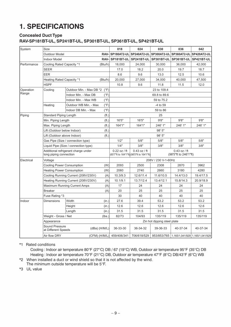
*1 Rated conditionsCooling : Indoor air temperature 80°F (27°C) DB / 67 (19°C) WB, Outdoor air temperature 95°F (35°C) DBHeating : Indoor air temperature 70°F (21°C) DB, Outdoor air temperature 47°F (8°C) DB/43°F (6°C) WB
*2 When installed a duct or wind shield so that it is not affected by the wind.The minimum outside temperature will be 5°F.
*3 UL value
System Size 018 024 030 036 042
Outdoor Model RAV- SP180AT2-UL SP240AT2-UL SP300AT2-UL SP360AT2-UL SP420AT2-UL
Indoor Model RAV- SP181BT-UL SP241BT-UL SP301BT-UL SP361BT-UL SP421BT-UL
– 10 –
2. FAN CHARACTERISTICS Back air intake
181 type 241 type
301 type 361, 421 type
Air Flow (cfm)
Ex
tern
al
Sta
tic
Pre
ssu
re (
in.W
G)
High(0.45 inWG)
High(0.35in.WG)
High(0.25in.WG)
High(0.15in.WG)
Low
Mid
Air Flow (cfm)
Ex
tern
al
Sta
tic
Pre
ssu
re (
in.W
G)
High(0.45 inW
High(0.35in.W
High(0.25in.W
High(0.15in.W
Mid
Low
Air Flow (cfm)
Ex
tern
al
Sta
tic
Pre
ssu
re (
in.W
G)
High(0.46 inWG)
High(0.35in.WG)
High(0.25in.WG)
High(0.15in.WG)
Mid
Low
Air Flow (cfm)
Ex
tern
al
Sta
tic
Pre
ssu
re (
in.W
G)
High(0.46 inWG)
High(0.35in.WG
High(0.25in.WG)
High(0.15in.WG)
Mid
Low
– 11 –
Under air intake
181 type 241 type
301 type 361, 421 type
Air Flow (cfm)
Ex
tern
al
Sta
tic
Pre
ssu
re (
in.W
G)
High(0.45 inWG)
High(0.35in.WG)
High(0.25in.WG
High(0.15in.WG)
Low
Mid
Air Flow (cfm)
Ex
tern
al
Sta
tic
Pre
ssu
re (
in.W
G)
High(0.45 inW
High(0.35in.W
High(0.25in.WG
High(0.15in.WG
Mid
Low
Air Flow (cfm)
Ex
tern
al
Sta
tic
Pre
ssu
re (
in.W
G)
High(0.46 inWG)
High(0.35in.WG)
High(0.25in.WG)
High(0.15in.WG)
Mid
Low
Air Flow (cfm)
Ex
tern
al
Sta
tic
Pre
ssu
re (
in.W
G)
High(0.46 inWG)
High(0.35in.WG)
High(0.25in.WG)
High(0.15in.WG)
Mid
Low
– 12 –
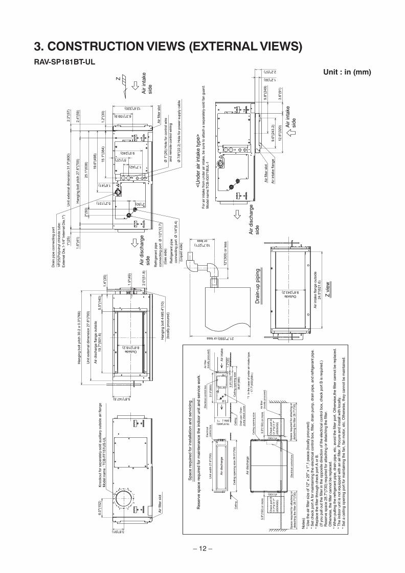
3. CONSTRUCTION VIEWS (EXTERNAL VIEWS)RAV-SP181BT-UL
Unit : in (mm)
– 13 –
RAV-SP241BT-ULUnit : in (mm)
– 14 –
RAV-SP301BT-UL, RAV-SP361BT-UL, RAV-SP421BT-ULUnit : in (mm)
– 15 –
4. SYSTEMATIC REFRIGERATING CYCLE DIAGRAM• Single type (Combination of 1 indoor unit and 1 outdoor unit)
(Indoor unit)
Refrigerant pipe at liquid side (Outer dia : ØB)
Refrigerant pipe at gas side (Outer dia : ØA)
Distributor (Strainer incorporated)
HeatingCooling
TCJ sensor
TC sensor
Air heatexchanger
To outdoor unit To outdoor unit
Dimension table
Indoor unit
RAV-SP18 type
RAV-SP24, 30, 36, 42 type
Outer diameter of refrigerant pipe (In (mm))
Gas side ØA Liquid side ØB
1/2” (12.7) 1/4” (6.4)
5/8” (15.9) 3/8” (9.5)
– 16 –
5. WIRING DIAGRAM
Contr
ol P.C
. board
for
Indoor
un
it
3
1
3 1
DMM
5
1 3 526
87
5
12
12
11
25
46
23
1 3 1
1
L1
L2
L
1 3 31
U
3
2
21
54
36
16
53
4
MS
FM
1
1.B
roke
n lin
e
ind
ica
te t
he
wirin
g a
t site
. L
on
g d
ash
ed
ind
ica
tes t
he
co
nn
ecto
r o
n t
he
co
ntr
ol P.C
. b
oa
rd.
ind
ica
tes t
he
pro
tectio
n g
rou
nd
.
sh
ort
da
sh
ed lin
e in
dic
ate
th
e a
cce
sso
rie
s.
53
12
45
46
4.
3.
2t°
2.
ind
ica
tes t
he
co
ntr
ol P.C
. b
oa
rd.
ind
ica
tes t
he
con
ne
ctio
n t
erm
ina
l.
ind
ica
tes t
he
te
rmin
al b
lock.
2 3 1 212
t°t°
1 1
AU
3U
42
1B
U4
U3
AB
13
5
S
L1
L2
S
Sym
bo
lP
art
s N
am
e
Co
nn
ecto
r
Tem
p s
en
so
r
Dra
in p
um
p M
oto
r
Fa
n M
oto
r
Flo
at S
witch
Ind
oor
tem
p s
en
so
r
Te
rmin
al B
lock
RY
1
TC
,TC
J
TB
01
,02
TA
DM
FM
FS
F3
01
L
CN
Re
lay
Fu
se
Rea
cto
r
Ind
oo
r u
nit
Gro
un
d s
cre
w
Ou
tdo
or
un
itG
rou
nd
scre
wC
en
tta
l R
em
ote
Co
ntr
ol
(So
ld s
ep
ara
tely
)
Wire
d R
em
ote
Co
ntr
ol
(So
ld s
ep
ara
tely
)
Ad
ap
ter
for
Wire
less R
em
ote
Co
ntr
ol
(So
ld s
ep
ara
tely
)
– 17 –
6. PARTS RATING
Model RAV-
Fan motor
Drain pump motor
Float switch
Reactor
TA sensor
TC sensor
TCJ sensor
Model RAV-
Fan motor
Drain pump motor
Float switch
Reactor
TA sensor
TC sensor
TCJ sensor
SP301BT-UL SP361BT-UL SP421BT-UL
MF-240U150-2A MF-240U150-1A
ADP-1406
FS-0218-102
CH-43-2Z-T
Lead wire length : 24.3 in (618mm)
Ø6, Lead wire length : 47.2 in (1200mm), Vinyl tube (Black)
Ø6, Lead wire length : 47.2 in (1200mm), Vinyl tube (Red)
SP181BT-UL SP241BT-UL
Ø6, Lead wire length : 47.2 in (1200mm), Vinyl tube (Black)
Ø6, Lead wire length : 47.2 in (1200mm), Vinyl tube (Red)
MF-240U150-2A
ADP-1406
FS-0218-102
CH-43-2Z-T
Lead wire length : 24.3 in (618mm)
– 18 –
7. REFRIGERANT R410AThis air conditioner adopts the new refrigerant HFC(R410A) which does not damage the ozone layer.The working pressure of the new refrigerant R410A is1.6 times higher than conventional refrigerant (R22).The refrigerating oil is also changed in accordancewith change of refrigerant, so be careful that water,dust, and existing refrigerant or refrigerating oil arenot entered in the refrigerant cycle of the airconditioner using the new refrigerant duringinstallation work or servicing time.The next section describes the precautions for airconditioner using the new refrigerant.Conforming to contents of the next section togetherwith the general cautions included in this manual,perform the correct and safe work.
7-1. Safety During Installation/ServicingAs R410A’s pressure is about 1.6 times higher thanthat of R22, improper installation/servicing may causea serious trouble. By using tools and materialsexclusive for R410A, it is necessary to carry outinstallation/servicing safely while taking the followingprecautions into consideration.1. Never use refrigerant other than R410A in an air
conditioner which is designed to operate withR410A.If other refrigerant than R410A is mixed, pressurein the refrigeration cycle becomes abnormally high,and it may cause personal injury, etc. by a rupture.
2. Confirm the used refrigerant name, and use toolsand materials exclusive for the refrigerant R410A.The refrigerant name R410A is indicated on thevisible place of the outdoor unit of the airconditioner using R410A as refrigerant.To prevent mischarging, the diameter of theservice port differs from that of R22.
3. If a refrigeration gas leakage occurs duringinstallation/servicing, be sure to ventilate fully.If the refrigerant gas comes into contact with fire, apoisonous gas may occur.
4. When installing or removing an air conditioner, donot allow air or moisture to remain in therefrigeration cycle.Otherwise, pressure in the refrigeration cycle maybecome abnormally high so that a rupture orpersonal injury may be caused.
5. After completion of installation work, check tomake sure that there is no refrigeration gasleakage.If the refrigerant gas leaks into the room, cominginto contact with fire in the fan-driven heater, spaceheater, etc., a poisonous gas may occur.
6. When an air conditioning system charged with alarge volume of refrigerant is installed in a smallroom, it is necessary to exercise care so that, evenwhen refrigerant leaks, its concentration does notexceed the marginal level.If the refrigerant gas leakage occurs and itsconcentration exceeds the marginal level, anoxygen starvation accident may result.
7. Be sure to carry out installation or removalaccording to the installation manual.Improper installation may cause refrigerationtrouble, water leakage, electric shock, fire, etc.
8. Unauthorized modifications to the air conditionermay be dangerous. If a breakdown occurs pleasecall a qualified air conditioner technician orelectrician.Improper repair may result in water leakage,electric shock and fire, etc.
7-2. Refrigerant Piping Installation7-2-1. Piping Materials and Joints Used
For the refrigerant piping installation, copper pipesand joints are mainly used.Copper pipes and joints suitable for the refrigerantmust be chosen and installed.Furthermore, it is necessary to use clean copperpipes and joints whose interior surfaces are lessaffected by contaminants.1. Copper Pipes
It is necessary to use seamless copper pipeswhich are made of either copper or copper alloyand it is desirable that the amount of residual oil isless than 0.0001 lbs / 32’ 10” (40 mg/10 m).Do not use copper pipes having a collapsed,deformed or discolored portion (especially on theinterior surface).Otherwise, the expansion valve or capillary tubemay become blocked with contaminants.As an air conditioner using R410A incurs pressurehigher than when using R22, it is necessary tochoose adequate materials.Thicknesses of copper pipes used with R410A areas shown in Table 7-2-1. Never use copper pipesthinner than 0.03” (0.8mm) even when it isavailable on the market.
– 19 –
1. JointsFor copper pipes, flare joints or socket joints are used. Prior to use, be sure to remove all contaminants.a) Flare Joints
Flare joints used to connect the copper pipes cannot be used for pipings whose outer diameter exceeds20 mm. In such a case, socket joints can be used.Sizes of flare pipe ends, flare joint ends and flare nuts are as shown in Tables 7-2-3 to 7-2-5 below.
b) Socket JointsSocket joints are such that they are brazed for connections, and used mainly for thick pipings whosediameter is larger than 0.79” (20 mm). Thicknesses of socket joints are as shown in Table 7-2-2.
Table 7-2-1 Thicknesses of annealed copper pipes
Outer diameter (In (mm))
1/4” (6.4)
3/8” (9.5)
1/2” (12.7)
5/8” (15.9)
Thickness (In (mm))
R410A R22
0.03” (0.80) 0.03” (0.80)
0.03” (0.80) 0.03” (0.80)
0.03” (0.80) 0.03” (0.80)
0.04” (1.00) 0.04” (1.00)
Table 7-2-2 Minimum thicknesses of socket joints
Reference outer diameter of copper pipe jointed(In (mm))
1/4” (6.4)
3/8” (9.5)
1/2” (12.7)
5/8” (15.9)
Minimum joint thickness(In (mm))
0.02” (0.50)
0.02” (0.60)
0.03” (0.70)
0.03” (0.80)
7-2-2. Processing of Piping Materials
When performing the refrigerant piping installation, care should be taken to ensure that water or dust does notenter the pipe interior, that no other oil other than lubricating oils used in the installed air conditioner is used,and that refrigerant does not leak. When using lubricating oils in the piping processing, use such lubricatingoils whose water content has been removed. When stored, be sure to seal the container with an airtight cap orany other cover.
1. Flare Processing Procedures and Precautionsa) Cutting the Pipe
By means of a pipe cutter, slowly cut the pipe so that it is not deformed.b) Removing Burrs and Chips
If the flared section has chips or burrs, refrigerant leakage may occur.Carefully remove all burrs and clean the cut surface before installation.
– 20 –
c) Insertion of Flare Nutd) Flare Processing
Make certain that a clamp bar and copper pipe have been cleaned.By means of the clamp bar, perform the flare processing correctly.Use either a flare tool for R410A or conventional flare tool.Flare processing dimensions differ according to the type of flare tool.When using a conventional flare tool, be sure to secure “dimensionA” by using a gauge for size adjustment.
Fig. 7-2-1 Flare processing dimensions
AØD
Table 7-2-3 Dimensions related to flare processing for R410A / R22
Table 7-2-4 Flare and flare nut dimensions for R410A
Table 7-2-5 Flare and flare nut dimensions for R22
A (In (mm))
Outer diameter
(In (mm))
1/4” (6.4)
3/8” (9.5)
1/2” (12.7)
5/8” (15.9)
Thickness
(In (mm))
0.03” (0.8)
0.03” (0.8)
0.03” (0.8)
0.04” (1.0)
Dimension (In (mm))
A B C D
0.36” (9.1) 0.36” (9.2) 0.26” (6.5) 0.51” (13)
0.52” (13.2) 0.53” (13.5) 0.38” (9.7) 0.79” (20)
0.65” (16.6) 0.63” (16.0) 0.51” (12.9) 0.91” (23)
0.78” (19.7) 0.75” (19.0) 0.63” (16.0) 0.98” (25)
Flare nut width
(In (mm))
0.67” (17)
0.87” (22)
1.02” (26)
1.14” (29)
Outer diameter
(In (mm))
1/4” (6.4)
3/8” (9.5)
1/2” (12.7)
5/8” (15.9)
3/4” (19.0)
Thickness
(In (mm))
0.03” (0.8)
0.03” (0.8)
0.03” (0.8)
0.04” (1.0)
0.04” (1.0)
Dimension (In (mm))
A B C D
0.36” (9.1) 0.36” (9.2) 0.26” (6.5) 0.51” (13)
0.51” (13.0) 0.53” (13.5) 0.38” (9.7) 0.79” (20)
0.64” (16.2) 0.63” (16.0) 0.51” (12.9) 0.79” (20)
0.76” (19.4) 0.75” (19.0) 0.63” (16.0) 0.91” (23)
0.92” (23.3) 0.94” (24.0) 0.76” (19.2) 1.34” (34)
Flare nut width
(In (mm))
0.67” (17)
0.87” (22)
0.94” (24)
1.06” (27)
1.42” (36)
– 21 –
2. Flare Connecting Procedures and Precautionsa) Make sure that the flare and union portions do not have any scar or dust, etc.b) Correctly align the processed flare surface with the union axis.c) Tighten the flare with designated torque by means of a torque wrench.
The tightening torque for R410A is the same as that for conventional R22.Incidentally, when the torque is weak, the gas leakage may occur.When it is strong, the flare nut may crack and may be made non-removable.When choosing the tightening torque, comply with values designated by manufacturers.Table 7-2-6 shows reference values.
NOTE:When applying oil to the flare surface, be sure to use oil designated by the manufacturer.If any other oil is used, the lubricating oils may deteriorate and cause the compressor to burn out.
43˚ to 45˚
45˚ to 46˚
B A C D
Fig. 7-2-2 Relations between flare nut and flare seal surface
Table 7-2-6 Tightening torque of flare for R410A [Reference values]
Outer diameter (In (mm))
1/4” (6.4)
3/8” (9.5)
1/2” (12.7)
5/8” (15.9)
Tightening torque (ft • lbs (N • m))
10 – 13 (14 – 18)
24 – 31 (33 – 42)
37 – 46 (50 – 62)
50 – 60 (68 – 82)
– 22 –
7-3. Tools7-3-1. Required Tools
Refer to the “4. Tools” (Page 8)
7-4. Recharging of RefrigerantWhen it is necessary to recharge refrigerant, charge the specified amount of new refrigerant according to thefollowing steps.
Connect the charge hose to packed valve service port at the outdoor unit’s gas side.
Recover the refrigerant, and check no refrigerant remains in the equipment.
(For refrigerant charging, see the figure below.)
Connect the charge hose of the vacuum pump adapter.
Open fully both packed valves at liquid and gas sides.
Place the handle of the gauge manifold Low in the fully opened position, and turn on the vacuum pump’s power switch. Then, evacuating the refrigerant in the cycle.
When the compound gauge’s pointer has indicated –101 kpa (–76 cmHg), place the handle Low in the fully closed position, and turn off the vacuum pump’s power switch.
Keep the status as it is for 1 to 2 minutes, and ensure that the compound gauge’s pointer does not return.
Set the refrigerant cylinder to the electronic balance, connect the connecting hose to the cylinder and the connecting port of the electronic balance, and charge liquid refrigerant.
(INDOOR unit) (Liquid side)
Refrigerant cylinder (With siphon pipe)
Check valve
(Gas side)
Open/Close valvefor charging
Electronic balance for refrigerant charging
Opened
(OUTDOOR unit)
Closed
Service port
Fig. 7-4-1 Configuration of refrigerant charging
1) Never charge refrigerant exceeding the specified amount.2) If the specified amount of refrigerant cannot be charged, charge refrigerant bit by bit in COOL mode.3) Do not carry out additional charging.
When additional charging is carried out if refrigerant leaks, the refrigerant composition changes in therefrigeration cycle, that is characteristics of the air conditioner changes, refrigerant exceeding the specifiedamount is charged, and working pressure in the refrigeration cycle becomes abnormally high pressure, andmay cause a rupture or personal injury.
– 23 –
1) Be sure to make setting so that liquid can be charged.2) When using a cylinder equipped with a siphon, liquid can be charged without turning it upside down.
It is necessary for charging refrigerant under condition of liquid because R410A is mixed type of refrigerant.Accordingly, when charging refrigerant from the refrigerant cylinder to the equipment, charge it turning thecylinder upside down if cylinder is not equipped with siphon.
Gauge manifold
[ Cylinder with siphon ] [ Cylinder without siphon ]
OUTDOOR unitGauge manifold
OUTDOOR unit
Refrigerantcylinder
Electronic balance
Refrigerantcylinder
Electronic balance
Siphon
Fig. 7-4-2
R410A refrigerant is HFC mixed refrigerant.Therefore, if it is charged with gas, the composition ofthe charged refrigerant changes and thecharacteristics of the equipment varies.
7-5. Brazing of Pipes7-5-1. Materials for Brazing
1. Silver brazing fillerSilver brazing filler is an alloy mainly composed ofsilver and copper.It is used to join iron, copper or copper alloy, and isrelatively expensive though it excels insolderability.
2. Phosphor bronze brazing fillerPhosphor bronze brazing filler is generally used tojoin copper or copper alloy.
3. Low temperature brazing fillerLow temperature brazing filler is generally calledsolder, and is an alloy of tin and lead.Since it is weak in adhesive strength, do not use itfor refrigerant pipes.
1) Phosphor bronze brazing filler tends to react withsulfur and produce a fragile compound watersolution, which may cause a gas leakage.Therefore, use any other type of brazing filler at ahot spring resort, etc., and coat the surface with apaint.
2) When performing brazing again at time ofservicing, use the same type of brazing filler.
7-5-2. Flux
1. Reason why flux is necessary• By removing the oxide film and any foreign matter
on the metal surface, it assists the flow of brazingfiller.
• In the brazing process, it prevents the metalsurface from being oxidized.
• By reducing the brazing filler’s surface tension, thebrazing filler adheres better to the treated metal.
– 24 –
2. Characteristics required for flux• Activated temperature of flux coincides with the
brazing temperature.• Due to a wide effective temperature range, flux
is hard to carbonize.• It is easy to remove slag after brazing.• The corrosive action to the treated metal and
brazing filler is minimum.• It excels in coating performance and is harmless
to the human body.As the flux works in a complicated manner asdescribed above, it is necessary to select anadequate type of flux according to the type andshape of treated metal, type of brazing filler andbrazing method, etc.
3. Types of flux• Noncorrosive flux
Generally, it is a compound of borax and boricacid.It is effective in case where the brazingtemperature is higher than 1472°F (800°C).
• Activated fluxMost of fluxes generally used for silver brazing arethis type.It features an increased oxide film removingcapability due to the addition of compounds suchas potassium fluoride, potassium chloride andsodium fluoride to the borax-boric acid compound.
4. Piping materials for brazing and usedbrazing filler/flux
Never use gas other than Nitrogen gas.
1) Do not enter flux into the refrigeration cycle.2) When chlorine contained in the flux remains within
the pipe, the lubricating oil deteriorates.Therefore, use a flux which does not containchlorine.
3) When adding water to the flux, use water whichdoes not contain chlorine (e.g. distilled water orion-exchange water).
4) Remove the flux after brazing.
7-5-3. Brazing
As brazing work requires sophisticated techniques,experiences based upon a theoretical knowledge, itmust be performed by a person qualified.In order to prevent the oxide film from occurring in thepipe interior during brazing, it is effective to proceedwith brazing while letting dry Nitrogen gas flow.
1. Brazing method to prevent oxidation1) Attach a reducing valve and a flow-meter to the
Nitrogen gas cylinder.2) Use a copper pipe to direct the piping material,
and attach a flow-meter to the cylinder.3) Apply a seal onto the clearance between the
piping material and inserted copper pipe forNitrogen in order to prevent backflow of theNitrogen gas.
4) When the Nitrogen gas is flowing, be sure tokeep the piping end open.
5) Adjust the flow rate of Nitrogen gas so that it islower than 0.05 m³/Hr or 2.9 psi (0.02 MPa) bymeans of the reducing valve.
6) After performing the steps above, keep theNitrogen gas flowing until the pipe cools down toa certain extent (temperature at which pipes aretouchable with hands).
7) Remove the flux completely after brazing.
Pipingmaterial
Copper - Copper
Copper - Iron
Iron - Iron
Used brazingfiller
Phosphor copper
Silver
Silver
Usedflux
Do not use
Paste flux
Vapor flux
Nitrogen gascylinder
Pipe
Flow meterM
Stop valve
From Nitrogen cylinder
Nitrogen gas
Rubber plug
Fig. 7-5-1 Prevention of oxidation during brazing
– 25 –
8. INDOOR CONTROL SUMMARY8-1. Indoor Control Block Diagram8-1-1. Connection of Wired Remote Control
BUSCommunication
circuit
Driver
DC5V
CPU
A B
L1 L2 S U3 U4
A B
Sameas left
Outdoorunit
Max. 8 units are connectable.
Indoor unit#1
Sub P.C. board(MCC-1431)
Main P.C. board (MCC-1510)
DC20V
DC5V
DC12V
DC280V
Drainpump
Indoor fan motor
Outside output
Main (Simple) wired remote control(Up to 2 sets)
Function setup
Key switch
Power circuit
EEPROM
TA sensor
TC sensor
TCJ sensor
HA
Remote controlcommunication circuit
Start/Alarm/ReadyThermostat ON
COOL/HEAT/FAN Float input
Fan motor control circuit
AC synchronoussignal input circuit
Display partLCD
Display partLED
Powercircuit
Remote controlcommunication circuit
CPU
Central controlcommunication circuit
Driver
L1 L2 S U3 U4
Centrralcontrol
SL2L1
U3 U4
#2
A B
Sameas left
Outdoorunit
Centrralcontrol
#3
Outdoor unit
Central control
Serial send/receive circuit
– 26 –
8-1-2. Connection of Wireless Remote Control Kit
L1L2
SU
3U
4
CP
U
DC
5V
AB
AB
Ind
oo
r u
nit
#1
Ou
tdo
or
un
it
Outd
oor
unit
Centr
al
contr
ol
Sam
eas
left
#2
L1L2
SU
3U
4
AB
Outd
oor
unit
Centr
al
contr
ol
Sam
eas
left
#3
Up to 8
units c
an b
e
connecte
d.
Em
erge
ncy
oper
atio
n S
W
Wirele
ss r
em
ote
contr
ol k
it
Se
nso
r P.C
. b
oa
rd
Pow
er
supp
ly c
ircui
t
Rem
ote
cont
rol
com
mun
icat
ion
circuit
Bu
zze
r
Se
nso
r circu
itD
isp
lay L
ED
Fu
nctio
n
se
ttin
g S
W
BU
SC
omm
unic
atio
nci
rcui
t
Driv
er
Sub
P.C
. boa
rd(M
CC
-143
1)
Mai
n P.
C. b
oard
(M
CC
-151
0)
DC
20V D
C5V
DC
12V
DC
280V
Dra
inpu
mp
Indo
or
fan
mot
or
Out
side
out
put
EE
PR
OM
TA s
enso
r
TC
sen
sor
TC
J se
nsor
HA
Sta
rt/A
larm
/Rea
dyT
herm
osta
t ON
CO
OL/
HE
AT/F
AN
Flo
at in
put
Ser
ial s
end/
rece
ive
circ
uit
Cen
tral
con
trol
Fan
mot
or
cont
rol c
ircui
t
AC
syn
chro
nous
sign
al in
put c
ircui
tP
ower
circ
uit
Rem
ote
cont
rol
com
mun
icat
ion
circ
uit
CP
U
Cen
tral
con
trol
com
mun
icat
ion
circ
uit
Driv
er
L1L2
S
U3
U4
– 27 –
8-1-3. Connection of Both Wired Remote Control and Wireless Remote Control Kit
L1L2
SU
3U
4
MC
UD
C5V
DC
5V
MC
U
AB
AB
EEPR
OM
Mai
n (S
impl
e) w
ired
rem
ote
cont
rol (
up to
2 u
nits
)
Pow
er
supp
ly
circ
uit
Func
tion
settin
g
Key
sw
itch
Rem
ote
cont
rol
com
mun
icat
ion
circ
uit
Dis
play
LC
D
Dis
play
LE
D
Indo
or u
nit
#1
Out
door
unit
Cen
tral
cont
rol
#2
Sam
eas
left
L1L2
SU
3U
4
AB
Out
door
unit
Cen
tral
cont
rol
#3
Sam
eas
left
Up
to 8
uni
ts
can
be c
onne
cted
.
Emer
genc
y op
erat
ion
SW
Wire
less
rem
ote
cont
rol k
it
Sen
sor
P.C
. boa
rd
Pow
er
supp
ly c
ircui
t
Rem
ote
cont
rol
com
mun
icat
ion
circ
uit
Buz
zer
Sen
sor
circ
uit
Dis
play
LE
D
Fun
ctio
n se
tting
SW
Out
door
uni
t
BU
SC
omm
unic
atio
nci
rcui
t
Driv
er
Sub
P.C
. boa
rd(M
CC
-143
1)
Mai
n P.
C. b
oard
(M
CC
-151
0)
DC
20V D
C5V
DC
12V
DC
280V
Dra
inpu
mp
Indo
or
fan
mot
or
Out
side
out
put
EE
PR
OM
TA s
enso
r
TC
sen
sor
TC
J se
nsor
HA
Sta
rt/A
larm
/Rea
dyT
herm
osta
t ON
CO
OL/
HE
AT/F
AN
Flo
at in
put
Ser
ial s
end/
rece
ive
circ
uit
Cen
tral
con
trol
Fan
mot
or
cont
rol c
ircui
t
AC
syn
chro
nous
sign
al in
put c
ircui
tP
o
*1 In
the
left
syst
em, s
et th
e w
irele
ss r
emot
e co
ntro
l sid
e
as th
e fo
llow
er r
emot
e co
ntro
l whe
n us
ing
the
mai
n (s
ub)
w
ired
rem
ote
cont
rol a
s th
e m
aste
r re
mot
e co
ntro
l
wer
circ
uit
Rem
ote
cont
rol
com
mun
icat
ion
circ
uit
CP
U
Cen
tral
con
trol
com
mun
icat
ion
circ
uit
Driv
er
L1L2
S
U3
U4
– 28 –
8-2. Control Outline
No.
When power
supply is reset
1) Distinction of outdoor unit
When the power supply is reset, the outdoor unit is
distinguished and the control is selected according to the
distinguished result.
2) Setting of indoor fan speed and existence of air direction
adjustment
Based on EEPROM data, select setting of the indoor fan
speed and the existence of air direction adjustment.
Fan speed (rpm)/
Air direction adjustment
1
Item Outline of specifications Remarks
When power
supply is reset
Remote controlcommand
Control outline
1) The operation mode is selected based on the operation mode
command on the remote control.
TA: Room temp.
TS: Setup temp.
TO: Outside temp.
K = deg
2
Room temp.
control
1) Adjustment range: Remote control setup temperature (°F [°C] )
∗ When use of remote sensor is set (with DN32), even when sensor value is within the
above range in HEAT or AUTO mode, the thermo. sensor turns OFF when TA sensor value
exceeds 95°F (35°C).
3
Air conditioner stops.
Fan operation
Cooling operation
Dry operation
Heating operation
STOP
FAN
COOL
DRY
HEAT
AUTO • COOL/HEAT operation mode is
automatically selected by TA,TS
and TO for operation.
• The operation is performed as
shown in the following figure
according to TA value at the first
time only. (In the range of TS +
α –1 < TA < TS + α + 1:
Cooling thermostat. OFF (Fan) /
Setup air volume operation
continues.)
Cooling thermostat. OFF (Fan) Setup air volume
Cooling operation
Heating operation
TA˚F [˚C]
–1.8 [–1.0]
TS + α
1.8 [1.0]
• α is corrected according to the outside temperature.
Outside temp.
No TO
TO ≥ 75.2°F (24°C)
75.2°F (24°C) > TO ≥ 64.4°F (18°C)
TO < 64.4°F (18°C)
TO trouble
Correction value (α)
0K
–1K
0K
+1K
0K
Wired type
Wireless type
COOL/DRY
64°F [18°C] to 84°F [29°C]
64°F [18°C] to 86°F [30°C]
HEAT
64°F [18°C] to 84°F [29°C]
61°F [16°C] to 86°F [30°C]
AUTO
64°F [18°C] to 84°F [29°C]
63°F [17°C] to 80°F [27°C]
– 29 –
–2.7 [–1.5]
TSC – TSH
+2.7 [+1.5]
Heating
(Cooling OFF)
(Cooling ON)
CoolingTA ˚F [˚C]
No.
3
4
5
Item
Room temp.control(Continued)
Automaticcapacity control
(GA control)
Automaticcooling/heatingcontrol
Outline of specifications
2) Using the CODE No. 06, the setup temperature in heatingoperation can be corrected.
operation frequency is instructed to the outdoor unit.
2) Cooling operation
Every 90 seconds, GA calculates TA-TS, the fluctuation,
and the correction amount of compressor frequency.
TA (n) – TS (n) : Room temp. differencen : Detecting countsTA (n-1) – TS (n): Room temp. fluctuationn – 1 : Detecting counts of 90 seconds before
3) Heating operation
Every 1 minute (60 sec.), GA calculates TA-TS, the
fluctuation, and the correction amount of compressor
frequency.
TS (n) – TA (n) : Room temp. differencen : Detecting countsTA (n) – TA (n – 1) : Room temp. fluctuationn – 1 : Detecting counts of 1 minute before
4) Dry operation
The frequency correction control is same as those of thecooling operation.
However the maximum frequency is limited to approxi-mately “S6”.
Note) When LOW is set up, the maximum frequency islimited to approximately “SB”.
1) The judgment of selecting Cooling/Heating mode is
carried out as shown below. When TA exceeds TSH
+2.7°F(+1.5°C) after 10 minutes at thermostat off, the
operation mode changes HEAT to COOL mode
When TA is lower TSC-2.7°F(-1.5°C) after 10 minutes at
thermostat off, the operation mode changes COOL to
HEAT mode.
2) For the automatic capacity control after judgment of
cooling/heating, see Item 4.3) For temperature correction of room temp. control at
automatic heating, see Item 3.
Remarks
Unless the sensor of the
remote control is
controlled, there is a shift
in the suction temperature
during heating operation.
TSC: Setup temp. incooling operation
TSH: Setup temp. inheating operation+ temp. correction ofroom temp. control
– 30 –
TA - TSC ˚F [˚C]+5.4 [+3.0]
+4.5 [+2.5]
+3.6 [+2.0]
+2.7 [+1.5]
+1.8 [+1.0]
+0.9 [+0.5]
0
–0.9 [–0.5]
HH(HH)
H+ (HH)
H (HH)
L+ (H+)
L (H)
L (H)
L (L+)
D
C
B
A
E
F
G
TSH - TA ˚F [˚C]<–0.9> –1.8 [<–0.5> –1.0]
<0>
<+0.9> +1.8 [<+0.5> +1.0]
<+1.8> +3.6 [<+1.0> +2.0]
<+2.7> +5.4 [<+1.5> +3.0]
<+3.6> +7.2 [<+2.0> +4.0]
L (L+)
L+ (H)
H (H+)
HH(HH)
H+(HH)
E
D
C
B
A
No.
6
Item
Fan speed control
Outline of specifications
1) Operation with (HH), (H), (L) or [AUTO] mode is carried outby the command from the remote control.
<COOL>
2) When the fan speed mode [AUTO] is selected, the fan speedvaries by the difference between TA and TS.
• Controlling works using thermostat of remote control is same as the case of using body thermostat.• If the fan speed has changed automatically, it is not changed for 3 minutes. However when the air volume changes, the fan speed changes.• When cooling operation starts, the fan speed will be selected along a down arrow in figure.• When "TA-TSC" is just on boundary, the fan speed won't change.• ( ) indicates the fan speed at aouotmatic cooling operation.
<HEAT>
The value with < > indicates the temperature at using remotecontrol thermostat. The value without < > indicates the temperature at using body thermostat of indoor unit.
• If the fan speed has changed automatically, it is not changed for 1 minute.• When heating operation starts, the fan speed will be selected along an up arrow in figure.• When "TSH-TA" is just on margin, the fan speed won't change.• ( ) indicates the fan speed at automatic heating operation.• In TC ≥ 140°F (60°C), the fan speed increases clarify 1 step.
Remarks
HH > H+ > H > L+ >L > UL
TC: Indoor heatexchanger sensortemperature
– 31 –
No.
6
Item
Fan speed control(Continued)
Outline of specifications
3) In heating operation, the fan speed changes to [UL] if thermostat is turned off.
4) If TA ≥ 77°F (25°C) when heating operation has started or defrost operation has
been cleared, the air conditioner operates with (H) mode or higher modefor 1
minute after TC entered in E zone of cold air draft preventive control (No. 7).
Remarks
Selection of highceiling type
CODE No.:[5d] or selection ofhigh ceiling on P.C.board SW01 and
Freeze preventive control(Low temperature release)
Outline of specifications
1) In heating operation, the indoor fan is controlled
based on the detected temperature of TC sensor
or TCJ sensor. As shown below, the upper limit of
the fan speed is restricted in spite of the fan speed
set on remote control.
However B zone is assumed as C zone for 6 minutes
after the compressor has started.
In defrost operation, the control value of TC is
shifted +10.8°F (+6°C).
1) The cooling operation (including Dry operation) is
performed as follows based on the detected
temperature of TC sensor or TCJ sensor.
When [J] zone is detected for 6 minutes
(Following figure), the commanded frequency of
compressor is decreased.
After then the commanded frequency changes
every 30 seconds while operation is performed in
[J] zone.
In [K] zone, time counting is interrupted and the
operation is held.
When [ I ] zone is detected, the timer is cleared
and the operation returns to the normal operation.
If the commanded frequency becomes S0
because the operation continues in [J] zone, the
return temperature A is raised from 41°F (5°C) to
53.6°F (12°C) until [ I ] zone is detected and the
indoor fan speed is operated with L tap.
In the heating operation, if the 4-way valve cannotbe reversed due to a trouble, etc. and keepsoperation with the cooling cycle, the freezepreventive control works when the followingconditions are satisfied.(However the temperature for J zone dashing
control is changed from 35.6°F (2°C) to 23°F (–5°C.))
<Conditions>
• When � or � is established 5 minutes afteractivation.
� TCn ≤ TC (n – 1) – 5
� TCn < TC (n – 1) – 1 and TCn ≤ TA < 41°F (5°C)
Remarks
In A zone while
thermostat is ON,
[PRE-HEAT
(Heating ready)]
isdisplayed.
TCJ:
Indoor heat exchangersensor temperature
TCn:
Tc temperature when 5minutes elapsed afteractivation
TC (n – 1):
Tc temperature at starttime
– 33 –
A
BL
N
MTC, TCJ
˚F [˚C]
No.
9
10
11
Item
High-temp.release control
Drain pumpcontrol
After-heatelimination
Outline of specifications
1) The heating operation is performed as follows based on thedetected temperature of TC sensor or TCJ sensor.
• When [M] zone is detected, the commanded frequency isdecreased. After then the commanded frequency changesevery 30 seconds while operation is performed in [M] zone.
• In [N] zone, the commanded frequency is held.
• When [L] zone is detected, the commanded frequency isreturned to the original value by approx. 6Hz every60 seconds.
Setup at shipment
Control temp. °F [°C]
A B
132.8 [56] (129.2 [54]) 125.6 [52] (125.6 [52])
NOTE:
When the operation has started or when TC or TCJ < 86°F (30°C)
at start of the operation or after operation start, The release
temperature is controlled between values in parentheses of A
and B.Same status as that when “thermostat-OFF”
1) In cooling operation (including Dry operation), the drainpump is usually operated.
2) If the float switch works while drain pump drives, thecompressor stops, the drain pump continues the operation,and a check code is output.
3) If the float switch works while drain pump stops, thecompressor stops and the drain pump operates. If the floatswitch keeps operating for approx. 4 minutes, a check codeis output.
When heating operation stops, in some cases, the indoor fanoperates with (L) for approx. 30 seconds.
Remarks
Check code [P10]
– 34 –
No.
12
13
Item
Frequency fixedoperation (Test run)
Outline of specifications
<In case of wired remote control>
1) When pushing [CHK] button for 4 seconds or more,[TEST] is displayed on the display screen and themode enters in Test run mode.
2) Push [ON/OFF] button.
3) Using [MODE] button, set the mode to [COOL] or[HEAT].
• Do not use other mode than [COOL]/[HEAT] mode.
• During test run operation, the temperature cannot beadjusted.
• Trouble is detected as usual.
• A frequency fixed operation is performed.
4) After the test run, push [ON/OFF] button to stop theoperation. (Display in the display part is same as theprocedure in Item 1.)
5) Push [CHK] button to clear the test run mode.([TEST] display in the display part disappears and thestatus returns to the normal stop status.)
Remarks
Command frequency isapproximately [S7]
For the Test run withthe wireless remotecontrol, refer to P 58.
∗ It is provided on theseparately sold typeTCB-AX21UL.
1) The filter sign is displayed with LC by sending the filter-reset signal to the remote control when the specified time (2500H) elapsed as a result of integration of the operation time of the indoor fan.
2) When the filter reset signal has been received fromthe remote control, time of the calculation timer iscleared. In this case, the measurement time is resetif the specified time has passed, and display on LCDdisappears.
2) The setup temperature is shifted (corrected) in therange not to lose the comfort ability according to inputvalues of various sensors.
3) Data (Input value room temp. TA, Outside temp. TO,
Airvolume, Indoor heat exchanger sensor temp. TC)
for20 minutes are taken the average to calculate
correction value of the setup temperature.
4) The setup temperature is shifted every 20 minutes,and the shifted range is as follows.
In cooling time: +1.5 to – 1.0KIn heating time: –1.5 to +1.0K
– 35 –
No.
15
16
Item
Max. frequency cutcontrol
Outline of specifications
1) This control is operated by selecting [AUTO] opera-tion mode.
2) COOL operation mode:It is controlled according to the following figure if TO< 82.4°F (28°C).
3) HEAT operation mode:It is controlled according to the following figure if TO> 59°F (15°C).
DC motor
+7.2 [+4]
+5.4 [+3]
TSC
TA˚F [˚C]
Normal control
Max. frequency is restricted to approximately the rated cooling frequency
TSH
–5.4 [–3]
–7.2 [–4]
TA˚F [˚C]
Normal control
Max. frequency is restricted to approximately the rated heating frequency
Remarks
1) When the fan operation has started, positioning ofthe stator and the rotor are performed.(Moves slightly with tap sound)
2) The motor operates according to the command fromthe indoor control.
Notes)
• When the f
• If static pressure of the used duct does not match
with the setup value of static pressure, which was
decided in the static pressure setting code No. [5D],
the air conditioner may stop or a check code may be
displayed.
an rotates while the air conditioner stopsdue to entering of outside air, etc, the air conditionermay operate while the fan motor stops.
• When a fan lock is found, the air conditioner stops,and trouble is displayed.
Check code [P12]
– 36 –
No.
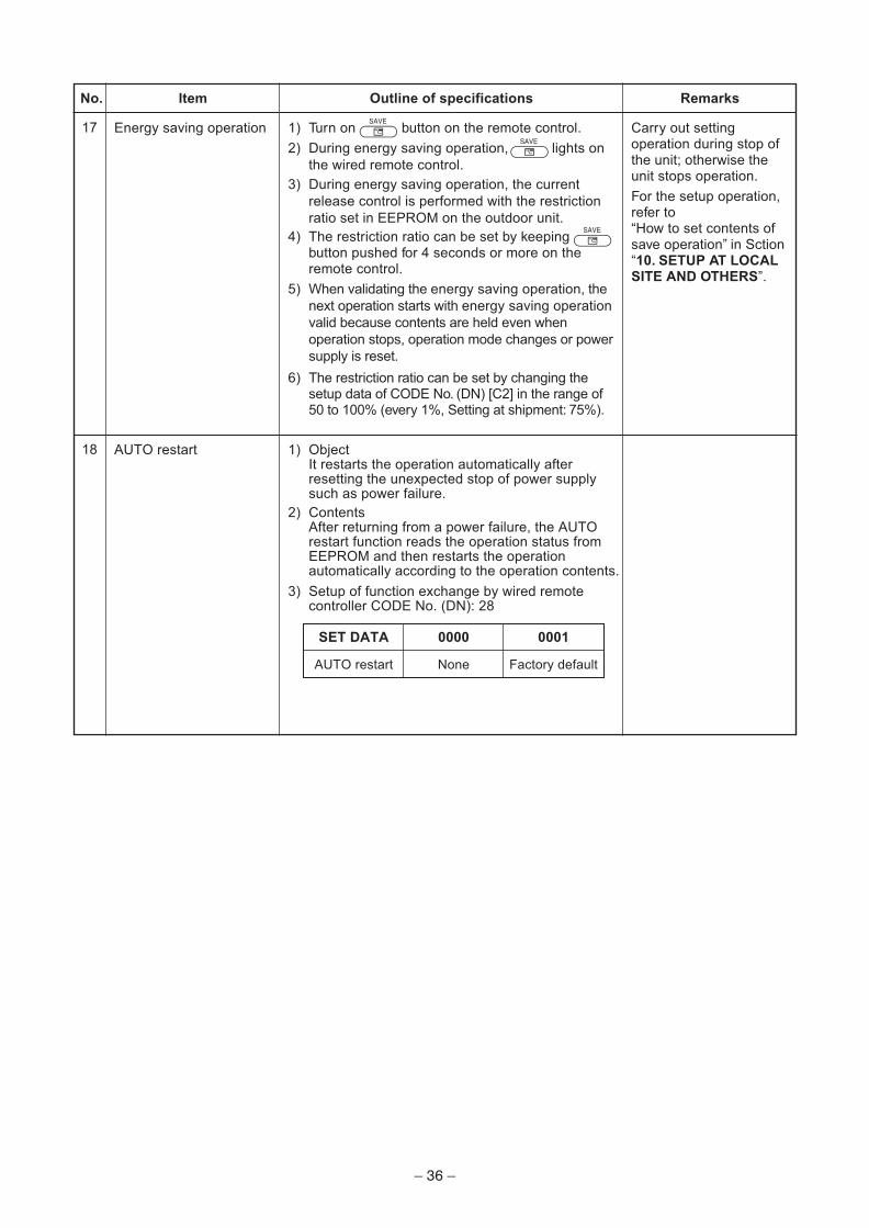
17
Item
Energy saving operation
Outline of specifications
1) Turn on SAVE
button on the remote control.
2) During energy saving operation, lights on
the wired remote control.
SAVE
3) During energy saving operation, the current
release control is performed with the restriction
ratio set in EEPROM on the outdoor unit.
4) The restriction ratio can be set by keeping SAVE
button pushed for 4 seconds or more on theremote control.
5) When validating the energy saving operation, the
next operation starts with energy saving operation
valid because contents are held even when
operation stops, operation mode changes or power
supply is reset.
6) The restriction ratio can be set by changing thesetup data of CODE No. (DN) [C2] in the range of50 to 100% (every 1%, Setting at shipment: 75%).
Remarks
Carry out settingoperation during stop ofthe unit; otherwise theunit stops operation.
For the setup operation,refer to“How to set contents ofsave operation” in Sction“10. SETUP AT LOCALSITE AND OTHERS”.
18 AUTO restart
SET DATA 0000 0001
1) ObjectIt restarts the operation automatically afterresetting the unexpected stop of power supplysuch as power failure.
2) ContentsAfter returning from a power failure, the AUTOrestart function reads the operation status fromEEPROM and then restarts the operationautomatically according to the operation contents.
3) Setup of function exchange by wired remotecontroller CODE No. (DN): 28
Setup at shipment: Linked operation of ON with operation ofindoor unit and OFF with stop
* The setup of single operation by FAN button on remotecontrol is executed from remote control. (DN = 31)
Start / stop input for HA (J01: In place / Removed =Pulse input (factory default) / Step input)
Enables / disables start / stop control via remote control
ON during operation (HA answerback signal)
ON while alarm ON
ON during defrosting of outdoor unit
ON when Real thermostat-ON (Comp. ON)
ON when operation mode is cooling line(Cool, Dry, Cooing/Heating AUTO cooling)
ON when operation mode is heating line(Heat, Cooling/Heating AUTO heating)
ON when indoor fan is ON
Generates test code “L30” and automatically shuts down airconditioner ( only if condition presists for 1 minute) (DN:2A = 2, atshipment from factory)
This check is used for operation check of indoor unit.(The specified operation such as indoor fan “H”, drain pump ON,etc. is executed without communication with outdoor unit orremote control.)
Display mode, communication is enabled by indoor unit andremote control only.(When power supply is turned on.)Timer short (Usual)
Indoor unit forced thermostat-OFF operation
ONOFFONOFFSW01<Bit 2>
Turn the switch to ON, when using the external static pressure function.Bit 1
Bit 2
Bit 1
Bit 2
No use
Input
No use
Input
ONONOFFOFFSW02<Bit 2>
External staticpressure
0.25 in.WG (62Pa)(Default)
0.35 in.WG(87Pa)
0.45 in.WG(112Pa)
0.15 in.WG(37Pa)
8-4. TCC-LINKThis indoor unit which has TCC-LINK adapter does not need “1:1” Model Connection Interface(TCBPCNT31TLUL) (sold separately).(Use terminals (U3, U4) for central control in the electrical box.)
– 39 –
9. TROUBLESHOOTING9-1. Summary of Troubleshooting<Wired remote control type>
1. Before troubleshooting1) Required tools/instruments• + and – screwdrivers, spanners, radio cutting pliers, nippers, push pins for reset switch• Tester, thermometer, pressure gauge, etc.2) Confirmation points before check
a) The following operations are normal.1. Compressor does not operate.
• Is not 3-minutes delay (3 minutes after compressor OFF)?• Is not the outdoor unit in standby status though the remote control reached the setup
temperature?• Does not timer operate during fan operation?• Is not an overflow trouble detected on the indoor unit?• Is not outside high-temperature operation controlled in heating operation?
2. Indoor fan does not rotate.• Does not cool air discharge preventive control work in heating operation?
3. Outdoor fan does not rotate or air volume changes.• Does not high-temperature release operation control work in heating operation?• Does not outside low-temperature operation control work in cooling operation?• Is not defrost operation performed?
4. ON/OFF operation cannot be performed from remote control.• Is not the control operation performed from outside/remote side?• Is not automatic address being set up?
(When the power is turned on at the first time or when indoor unit address setting is changed, theoperation cannot be performed for maximum approx. 5 minutes after power-ON.)
• Is not being carried out a test run by operation of the outdoor control?b) Did you return the wiring to the initial positions?c) Are connecting wires of indoor unit and remote control correct?
2. Troubleshooting procedureWhen a trouble occurred, check the parts along with the following procedure.
NOTE :For cause of a trouble, power conditions or malfunction/erroneous diagnosis of microcomputer due to outernoise is considered except the items to be checked.If there is any noise source, change the cables of the remote control to shield cables.
Trouble Confirmation of check code display Check trouble location or trouble part→ →
– 40 –
<Wireless remote control type>
1. Before troubleshooting1) Required tools/instruments
• + and – screwdrivers, spanners, radio cutting pliers, nippers, etc.• Tester, thermometer, pressure gauge, etc.
2) Confirmation points before checka) The following operations are normal.
1. Compressor does not operate.• Is not 3-minutes delay (3 minutes after compressor OFF)?• Is not the outdoor unit in standby status though the remote control reached the setup
temperature?• Does not timer operate during fan operation?• Is not an overflow trouble detected on the indoor unit?• Is not outside high-temperature operation controlled in heating operation?
2. Indoor fan does not rotate.• Does not cool air discharge preventive control work in heating operation?
3. Outdoor fan does not rotate or air volume changes.• Does not high-temperature release operation control work in heating operation?• Does not outside low-temperature operation control work in cooling operation?• Is not defrost operation performed?
4. ON/OFF operation cannot be performed from remote control.• Is not forced operation performed?• Is not the control operation performed from outside/remote side?• Is not automatic address being set up?• Is not being carried out a test run by operation of the outdoor control?
b) Did you return the wiring to the initial positions?c) Are connecting wires between indoor unit and receiving unit correct?
2. Troubleshooting procedure(When the power is turned on at the first time or when indoor unit address setting is changed, the operationcannot be performed for maximum approx. 5 minutes after power-ON.)When a trouble occurred, check the parts along with the following procedure.
1) Outline of judgmentThe primary judgment to check where a trouble occurred in indoor unit or outdoor unit is performed withthe following method.
Trouble → → Check trouble locationor trouble part
Confirmation of lamp display(wireless remote control is connected)
– 41 –
9-2. Troubleshooting9-2-1. Outline of judgment
The primary judgment to check whether a trouble occurred in the indoor unit or outdoor unit is carried out withthe following method.Method to judge the erroneous position by flashing indication on the display part of the indoor unit(sensors of the receiving part)The indoor unit monitors the operating status of the air conditioner, and the blocked contents of self-diagnosisare displayed restricted to the following cases if a protective circuit works.
∗1: These are representative examples and the check code differs according to the outdoor unit to be combined.
: Go off, : Go on, : Flash (0.5 sec.)
Lamp indication
Operation Timer Ready
No indication at all
Operation Timer Ready
Flash
Operation Timer Ready
Flash
Operation Timer Ready
Alternate flash
Operation Timer Ready
Alternate flash
Check code
—
E01
E02
E03
E08
E09
E10
E18
E04
P10
P12
P03
P04
P05
P07
P15
P19
P20
P22
P26
P29
P31
Cause of trouble occurrence
Power supply OFF or miswiring between receiving unit and indoor unit
Receiving troubleReceiving unit
Miswiring or wire connection troubleSending trouble
Communication stop
between receiving unit and indoor unit
Duplicated indoor unit No.Setup trouble
Duplicated master units of remote control
Communication trouble between CPUs on indoor unit P.C. board
Wire connection trouble between indoor units, Indoor power OFF(Communication stop between indoor header and follower)
Miswiring between indoor unit and outdoor unit or connection trouble(Communication stop between indoor and outdoor units)
Overflow was detected.Protective device of indoor unit worked.
Indoor DC fan trouble
Outdoor unit discharge temp. trouble Protective device of ∗1Outdoor high pressure system trouble outdoor unit worked.
Negative phase detection trouble
Heat sink overheat trouble Outdoor unit trouble
Gas leak detection trouble
4-way valve system trouble (Indoor or outdoor unit judged.)
Outdoor unit high pressure protection
Outdoor unit: Outdoor unit troubleProtective device of
Outdoor unit: Inverter Idc operation ∗1
Outdoor unit: Position detection troubleoutdoor unit worked.
Stopped because of trouble of other indoor unit in a group(Check codes of E03/L03/L07/L08)
– 42 –
∗1: These are representative examples and the check code differs according to the outdoor unit to be combined.
Lamp indication
Operation Timer Ready
Alternate flash
Operation Timer Ready
Alternate flash
Operation Timer Ready
Simultaneous flash
Operation Timer Ready
Simultaneous flash
Operation Timer Ready
Flash
Operation Timer Ready
Simultaneous flash
Operation Timer Ready
Simultaneous flash
Check code
F01
F02
F10
F04
F06
F07
F08
F12
F13
F15
F29
F31
H01
H02
H03
H04
H06
L03
L07
L08
L09
L10
L20
L29
L30
L31
Cause of trouble occurrence
Heat exchanger sensor (TCJ) trouble
Heat exchanger sensor (TC) trouble Indoor unit sensor trouble
Heat exchanger sensor (TA) trouble
Discharge temp. sensor (TD) trouble
Temp. sensor (TE) trouble
Temp. sensor (TL) trouble
Temp. sensor (TO) trouble Sensor trouble of outdoor unit ∗1
Temp. sensor (TS) trouble
Temp. sensor (TH) trouble
Temp. Sensor miswiring (TE, TS)
Indoor EEPROM trouble
Outdoor EEPROM trouble
Compressor break down
Compressor lock
Current detection circuit trouble Outdoor compressor system trouble ∗1
Case thermostat worked.
Outdoor unit low pressure system trouble
Duplicated master indoor units
There is indoor unit of group connection → AUTO addressin individual indoor unit.
* If group construction andUnsetting of group address address are not normalMissed setting when power supply turned on,(Unset indoor capacity) automatically goes to address
setup mode.
Unset model type (Service board)
Duplicated indoor central addresses
Outdoor unit and other trouble Others
Outside interlock trouble
Negative phase trouble
– 43 –
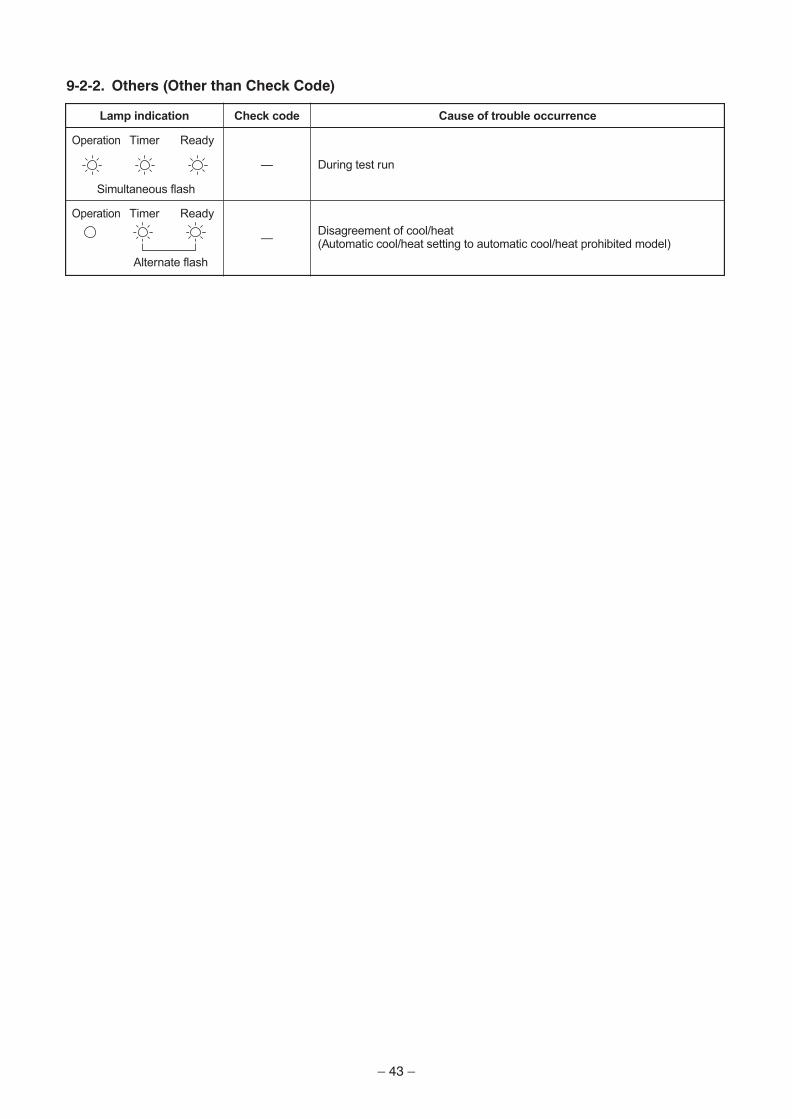
9-2-2. Others (Other than Check Code)
Lamp indication
Operation Timer Ready
Simultaneous flash
Operation Timer Ready
Alternate flash
Check code
—
—
Cause of trouble occurrence
During test run
Disagreement of cool/heat(Automatic cool/heat setting to automatic cool/heat prohibited model)
– 44 –
9-2-
3.C
hec
k C
od
e L
ist
(In
do
or)
� : G
o o
n, �
: F
lash
,
: G
o o
ff
A
LT (
Alte
rna
te):
Alte
rna
te f
lash
ing
wh
en
th
ere
are
tw
o f
lash
ing
LE
D
S
IM (
Sim
ulta
ne
ou
s):
Sim
ulta
ne
ou
s f
lash
ing
wh
en
th
ere
are
tw
o f
lash
ing
LE
D
(In
do
or
un
it d
ete
cte
d)
� W
hen this
warn
ing w
as d
ete
cte
d b
efo
re g
roup c
onstr
uction/a
ddre
ss c
heck fin
ish a
t pow
er
supply
was turn
ed o
n, th
e m
ode s
hifts
auto
matically
to A
UT
O a
ddre
ss s
etu
p m
ode.
(Re
mo
te c
on
tro
l d
ete
cte
d)
(Ce
ntr
al
co
ntr
ol
dev
ice
s d
ete
cte
d)
Ch
eck c
od
e in
dic
ati
on
TC
C-L
INK
cen
tral &
Wir
ed
rem
ote
co
ntr
ol
E03
E04
E08
E10
E18
F01
F02
� �F
10
F29
L03
L07
L08
L09
L20
L30
P01
P10
P12
P19
P31
� � � � � � �
� � � � � � � � � � � � � � � �
� � � � � � � � � � � �
O O O O O O O O × × × × × O × × × × O O
× × × × × × × × × × × × × × × × × × × ×
Sen
so
r la
mp
in
dic
ati
on
Blo
ck in
dic
ati
on
Opera
tion T
imer
Ready
Fla
sh
ALT
ALT
ALT
SIM
SIM
SIM
SIM
SIM
SIM
SIM
ALT
ALT
ALT
ALT
ALT
Rep
resen
tati
ve d
efe
cti
ve p
osit
ion
Regula
r com
munic
ation tro
uble
betw
een indoor
and
rem
ote
contr
ol
Indoor/
Outd
oor
seri
al to
ruble
Duplic
ate
d indoor
addre
sses
�C
om
munic
ation tro
uble
betw
een indoor
MC
U
Regula
r com
munic
ation tro
uble
betw
een
indoor
maste
r and follo
wer
units
Indoor
unit, H
eat exchanger
(TC
J)
trouble
Indoor
unit, H
eat exchanger
(TC
) tr
ouble
Indoor
unit, R
oom
tem
p. s
ensor
(TA
) tr
ouble
Indoor
unit, oth
er
indoor
P.C
. board
tro
uble
Duplic
ate
d s
ettin
g o
f in
door
gro
up h
eader
unit
�T
here
is g
roup c
able
in indiv
idual in
door
unit.
�U
nset in
door
gro
up a
ddre
ss
�U
nset in
door
capacity
Duplic
ate
d c
entr
al contr
ol syste
m a
ddre
ss
Outs
ide tro
uble
input to
indoor
unit (
Inte
rlock)
Indoor
unit, A
C fan tro
uble
Indoor
unit, ove
rflo
w d
ete
ction
Indoor
unit, D
C fan tro
uble
4-w
ay v
alv
e s
yste
m tro
uble
Oth
er
indoor
unit tro
uble
Exp
lan
ati
on
of
tro
ub
le c
on
ten
ts
No c
om
munic
ation fro
m r
em
ote
contr
ol and n
etw
ork
adapte
r(A
lso n
o c
om
munic
ation fro
m c
entr
al contr
ol syste
m)
There
is tro
uble
on s
erial com
munic
ation b
etw
een indoor
and o
utd
oor
units
Sam
e a
ddre
ss a
s y
ours
was d
ete
cte
d.
MC
U c
om
munic
ation tro
uble
betw
een m
ain
moto
r and m
icro
com
pute
r
Regula
r com
munic
ation b
etw
een indoor
header
and follo
wer
units is im
possib
le,
Com
munic
ation b
etw
een tw
in m
aste
r (m
ain
) and follo
wer
(sub)
units is im
possib
le.
Open/s
hort
was d
ete
cte
d o
n h
eat exchanger
(TC
J).
Open/s
hort
was d
ete
cte
d o
n h
eat exchanger
(TC
).
Open/s
hort
was d
ete
cte
d o
n r
oom
tem
p. s
ensor
(TA
).
EE
PR
OM
tro
uble
(O
ther
trouble
may b
e d
ete
cte
d. If n
o tro
uble
, auto
matic
addre
ss is
repeate
d.
There
are
multip
le h
eader
units in a
gro
up.
When e
ven o
ne g
roup c
onnection indoor
unit e
xis
ts in indiv
idual in
door
unit.
Indoor
gro
up a
ddre
ss is u
nset.
Capacity o
f in
door
unit is u
nset.
Duplic
ate
d s
ettin
g o
f centr
al contr
ol syste
m a
ddre
ss
Abnorm
al sto
p b
y o
uts
ide tro
uble
(C
N80)
input
An tro
uble
of in
door
AC
fan w
as d
ete
cte
d. (F
an m
oto
r th
erm
al re
lay w
ork
ed.)
Flo
at sw
itch w
ork
ed.
Indoor
DC
fan tro
uble
(O
ver-
curr
ent/Lock, etc
.) w
as d
ete
cte
d.
In h
eatin
g o
pera
tion, an tro
uble
was d
ete
cte
d b
y tem
p. dow
n o
f in
door
heat exchanger
sensor.
Follo
wer
unit in g
roup c
annot opera
te b
y w
arn
ing fro
m [E
03/L
03/L
07/L
08] of m
aste
r unit.
Air
co
nd
itio
ner
op
era
tio
n
Au
tom
ati
cO
pera
tio
nre
set
co
nti
nu
ati
on
Ch
eck c
od
e in
dic
ati
on
Wir
ed
rem
ote
co
ntr
ol
E01
E02
E09
— — ×
— —
� � �
Sen
so
r la
mp
in
dic
ati
on
Blo
ck in
dic
ati
on
Opera
tion T
imer
Ready
Fla
sh
Rep
resen
tati
ve d
efe
cti
ve p
osit
ion
No m
aste
r re
mote
contr
ol, R
em
ote
contr
ol
com
munic
ation (
Receiv
e)
trouble
Rem
ote
contr
ol com
munic
ation (
Send)
trouble
Duplic
ate
d m
aste
r re
mote
contr
ol
Exp
lan
ati
on
of
tro
ub
le c
on
ten
ts
Sig
nal cannot be r
eceiv
ed fro
m indoor
unit.
Maste
r re
mote
contr
ol w
as n
ot set. (
inclu
din
g 2
rem
ote
contr
ols
)
Sig
nal cannot be s
ent to
indoor
unit.
In 2
-rem
ote
contr
ol contr
ol, b
oth
were
set as h
eader.
(Indoor
maste
r unit s
tops w
arn
ing a
nd follo
wer
unit c
ontinues o
pera
tion.)
Air
co
nd
itio
ner
op
era
tio
n
Au
tom
ati
cO
pera
tio
nre
set
co
nti
nu
ati
on
Ch
eck c
od
e in
dic
ati
on
TC
C-L
INK
cen
tral
C05
C06
C12
P30
Sen
so
r la
mp
in
dic
ati
on
Blo
ck in
dic
ati
on
Opera
tion T
imer
Ready
Fla
sh
Is n
ot dis
pla
yed.
(Com
mon u
se o
fre
mote
contr
ol, e
tc.)
—
By w
arn
ing u
nit
(Above
-mentioned)
Rep
resen
tati
ve d
efe
cti
ve p
osit
ion
Centr
al contr
ol syste
m c
om
munic
ation (
send)
trouble
Centr
al contr
ol syste
m c
om
munic
ation (
receiv
e)
trouble
Genera
l-purp
ose d
evic
e c
ontr
ol in
terf
ace b
atc
hed w
arn
ing
Gro
up follo
wer
unit is
defe
ctive.
Exp
lan
ati
on
of
tro
ub
le c
on
ten
ts
Sig
nal sendin
g o
pera
tion o
f centr
al contr
ol syste
m is im
possib
le.
There
are
multip
le s
am
e c
entr
al devic
es.
Sig
nal re
ceiv
ing o
pera
tion o
f centr
al contr
ol syste
m is im
possib
le.
An tro
uble
on d
evic
e c
onnecte
d to g
enera
l-purp
ose d
evic
e c
ontr
ol in
terf
ace o
f exclu
siv
e to
TC
C-L
INK
Gro
up follo
wer
unit is
defe
ctive.
(For
rem
ote
contr
ol, a
bove-m
entioned [
∗∗∗]
deta
ils a
re d
ispla
yed w
ith u
nit N
o.
Air
co
nd
itio
ner
op
era
tio
n
Au
tom
ati
cO
pera
tio
nre
set
co
nti
nu
ati
on
— — — —
— — — —
NO
TE
:E
ve
n f
or
the
sa
me
co
nte
nts
of
tro
ub
le s
uch
as c
om
mu
nic
atio
n t
rou
ble
, th
e d
isp
lay o
f ch
eck c
od
e m
ay d
iffe
r a
cco
rdin
g t
o d
ete
ctio
n d
evic
e.
Wh
en
re
mo
te c
on
tro
l o
r ce
ntr
al co
ntr
ol d
ete
cts
a t
rou
ble
, it is n
ot
ne
ce
ssa
rily
re
late
d t
o o
pe
ratio
n o
f th
e a
ir c
on
ditio
ne
r. I
n t
his
lis
t, t
he
ch
eck c
od
es t
ha
t o
utd
oo
r u
nit d
ete
cts
are
no
t d
escri
be
d.
– 45 –
Trouble detected by indoor unit
Operation of diagnostic function
Checkcode
E03
E04
E08
L03
L07
L08
L09
L30
P10
P12
P19
P31
F01
F02
F10
F29
E10
E18
Cause of operation
No communication from remotecontrol (including wireless) andcommunication adapter
The serial signal is not output fromoutdoor unit to indoor unit.
• Miswiring of inter-unit wire
• Defective serial sending circuit onoutdoor P.C. board
• Defective serial receiving circuit onindoor P.C. board
• After heating operation has started,indoor heat exchangers temp. isdown.
Own unit stops while warning is outputto other indoor units.
Coming-off, disconnection or short ofindoor heat exchanger temp. sensor(TCJ)
Coming-off, disconnection or short ofindoor heat exchanger temp. sensor(TC)
Coming-off, disconnection or short ofindoor heat exchanger temp. sensor(TA)
Indoor EEPROM trouble
• EEPROM access trouble
Communication trouble between indoorMCU
• Communication trouble between fan
driving MCU and main MCU
Regular communication trouble betweenindoor aster and follower units andbetween main and sub units
Status ofair conditioner
Stop(Automatic reset)
Stop(Automatic reset)
Stop
Stop
Stop
Stop
Stop
Stop(Automatic reset)
Stop(Follower unit)
(Automatic reset)
Stop(Automatic reset)
Stop(Automatic reset)
Stop(Automatic reset)
Stop(Automatic reset)
Stop(Automatic reset)
Stop(Automatic reset)
Condition
Displayed whentrouble isdetected
Displayed whentrouble isdetected
Displayed whentrouble isdetected
Displayed whentrouble isdetected
Displayed whentrouble isdetected
Displayed whentrouble isdetected
Displayed whentrouble isdetected
Displayed whentrouble isdetected
Displayed whentrouble isdetected
Displayed whentrouble isdetected
Displayed whentrouble isdetected
Displayed whentrouble isdetected
Displayed whentrouble isdetected
Displayed whentrouble isdetected
Displayed whentrouble isdetected
Judgment and measures
1. Check cables of remote control and communication adapters.
• Remote control LCD display OFF (Disconnection)
• Central remote control [97] check code
1. Outdoor unit does not completely operate.
• Inter-unit wire check, correction of miswiring
• Check outdoor P.C. board. Correct wiring of P.C. board.
2. When outdoor unit normally operatesCheck P.C. board (Indoor receiving / Outdoor sending).
1. Check whether remote control connection (Group/Individual)was changed or not after power supply turned on(Finish of group construction/Address check).
* If group construction and address are not normal when thepower has been turned on, the mode automatically shifts toaddress setup mode. (Resetting of address)
1. Set indoor capacity (DN=11)
1. Check outside devices.
2. Check indoor P.C. board.
1. Trouble of drain pump
2. Clogging of drain pump
3. Check float switch.
4. Check indoor P.C. board.
1. Position detection trouble
2. Over-current protective circuit of indoor fan driving unit operated.
3. Indoor fan locked.
4. Check indoor P.C. board.
1. Check 4-way valve.
2. Check 2-way valve and check valve.
3. Check indoor heat exchanger (TC/TCJ).
4. Check indoor P.C. board.
1. Judge follower unit while master unit is [E03], [L03], [L07] or [L08].
Trouble detected by remote control or central control
*2 The check code cannot be displayed by the wired remote control.(Usual operation of air conditioner becomes unavailable.)For the wireless models, a trouble is notified with indication lamp.
*3 This trouble is related to communication of remote control (A, B), central system (U3, U4), and [E01], [E02],[E03], [E09] or [E18] is displayed or no check display on the remote control according to the contents.
Operation of diagnostic function
Check code
Not displayed at all(Operation onremote controlis impossible.)
E01
∗2
E02
E09
L20
Central controlL20
—
∗3
Central control(Send)
C05(Receive)
C06
—
Central controlP30
Cause of operation
No communication with master indoor unit
• Remote control wiring is not correct.
• Power of indoor unit is not turned on.
• Automatic address cannot be completed.
No communication with master indoor unit
• Disconnection of inter-unit wire betweenremote control and master indoor unit(Detected by remote control side)
Signal send trouble to indoor unit(Detected by remote control side)
There are multiple main remote controls.(Detected by remote control side)
Duplicated indoor central addresses oncommunication of central control system(Detected by indoor/central control side)
Communication circuit trouble of centralcontrol system(Detected by central control side)
Indoor Gr sub unit trouble(Detected by central control side)
Status ofair conditioner
Stop
Stop(Automatic reset)
∗ If center exists,operation continues.
Stop(Automatic reset)
∗ If center exists,operation continues.
Stop(Sub unit
continues operation.)
Stop(Automatic reset)
Continues(By remote control)
Continuation/Stop(According
to each case)
Condition
—
Displayed whentrouble isdetected
Displayed whentrouble isdetected
Displayed whentrouble isdetected
Displayed whentrouble isdetected
Displayed whentrouble isdetected
Displayed whentrouble isdetected
Judgment and measures
Power supply trouble of remote control, IndoorEEPROM trouble
1. Check power supply voltage. (AC208V / 230V ± 10%)
2. Overload operation of refrigerating cycle
1. Trouble of compressor (Lock, etc.): Replace compressor.
2. Wiring trouble of compressor (Open phase)
1. Check outdoor P.C. board. (AC current detection circuit)
Operation of diagnostic function
– 48 –
Operation of diagnostic function
Check code
P03
H04
P04
P05
P20
P22
P26
P29
Cause of operation
Discharge temp. trouble
∗ Discharge temp. (TD) overspecified value was detected.
Case thermostat operation
∗ Abnormal overheat of compressor
High-pressure SW trouble
Power supply voltage trouble
High pressure protective operation
• During cooling operation, outdoortemp. sensor (TL) detectedtemperature over specified temp.
• During heating operation, indoortemp. sensor (TC, TCJ) detectedtemperature over specified temp.
Outdoor fan system trouble
Short-circuit trouble of compressordriving element
Position detection circuit trouble
Status ofair conditioner
Stop
Stop
Stop
Stop
Stop
Stop
Stop
Stop
Condition
Displayed whentrouble is detected
Displayed whentrouble is detected
Displayed whentrouble is detected
Displayed whentrouble is detected
Displayed whentrouble is detected
Displayed whentrouble is detected
Displayed whentrouble is detected
Displayed whentrouble is detected
Judgment and measures
1. Check refrigerating cycle (Gas leak)
2. Trouble of electronic expansion valve
3. Check discharge temp. sensor (TD).
1. Check case thermostat and connector.
2. Check gas leak, recharge
3. Check full open of service valve.
4. Check PMV (Pulse Motor Valve).
5. Check broken pipe.
• Check full-open of service valve.
• Check outdoor fan trouble.
• Check outdoor fan motor trouble.
• Check clogging of outdoor PMV.
• Check loading of indoor/outdoor heat exchangers.
• Short-circuit of outdoor discharge/suction air
• Check outdoor P.C. board (I/F) trouble.
• Check trouble of fan system (air volume drop) at indoor side.
• Check miswiring of communication line between indoor andoutdoor.
• Check overcharge of refrigerant.
1. Check power supply voltage. (AC208V / 230V ± 10%)
1. Check outdoor heat exchanger sensor (TL).
2. Check indoor heat exchanger sensor (TC, TCJ).
3. Check full open of service valve.
4. Check indoor/outdoor fan.
5. Check PMV (Pulse Motor Valve).
6. Check clogging and short circuit of indoor/outdoor heatexchanger.
7. Overcharge of refrigerant. Recharge
1. Check lock of fan motor.
2. Check power supply voltage. (AC208V / 230V ± 10%)
3. Check outdoor P.C. board.
1. When performing operation while taking-off compressorwire, P26 trouble occurs. Check control P.C. board.
2. When performing operation while taking-off compressorwire, an trouble does not occur. (Compressor rare short)
1. Check control P.C. board.
– 49 –
Is inter-unit wire of A and B normal?
Is group control operation?
Is power of all indoor units turned on?
Is power supplied to remote control?AB terminal: Approx. DC18V
Are 2 remote controls setwithout master unit?
Are 2 master units set in2 remote controls?
Is there no disconnection orcontact trouble of connector on harness
from terminal block of indoor unit?
Check power connection of indoor unit.(Turn on power again.)
Check indoor P.C. board.Defect → Replace
Check remote control P.C. board.Defect → Replace
Correct as a header unitand a follower unit.
Check remote control P.C. board.Defect → Replace
Correct a header unit/a follower unit.(Remote control address connector)
Correct connection of connector.Check circuit wiring.
Correct inter-unit wireof remote control
YES
YES
YES
YES
YES
YES
YES
NO
NO
NO
NO
NO
NO
NO
9-2-4. Diagnostic Procedure for Each Check Code (Indoor Unit)
Check code[E01]
[E09]
– 50 –
Measure within 20 seconds from power on.
Does outdoor unit work?
Check indoor unit board.→ Replace defective board.
Check power supply voltage.Correct lines.
Check and eliminate noise, etc.
Is there no disorder of power supply?
Is case thermostat sensor working?
Is group address set correctly?
Check indoor control P.C. board(MCC-1510).
Defect → Replace
Are connectors from indoor unitand outdoor unit connected normally? Correct connector connection.
Is 280V DC applied across IPDUmain circuit capacitor? Replace IPDU.
Is case thermostat sensor connected?(CN500)
Check and correctrefrigerant volume.
Correct connector connection.
Check CODE No. “14”.
Are L1, L2, S wires normal? Correct wires.
Is 280V DC supplied to CDB? (CN03) Replace IPDU.
Does voltage between indoor unit terminalL2 and S fluctuate? (0-140V DC)
Check MCC-1510 P.C. board.→ Replace it if necessary.
Is 7V DC supplied to CDB?Is CN06 – CN800 connection normal?
Replace IPDU.Correct connector connection.
Check MCC-1510 P.C. board.→ Replace it if necessary.
Check CDB.→ Replace it if necessary.
+|
3
2
1
Black
White
Terminal block
YES
YES
YES
YES
YES
YES
YES
YES
YES
NO
NO
NO
NO
NO
NO
NO
NO
NO
YES
YES
NO
NO
[E04]
[E10]
– 51 –
Is not yet capacity settingof indoor unit set up?
Is group control operation?
Is power of all indoor units turned on?
Is inter-unit wireof A and B normal?
Is there no contact troubleof indoor/outdoor inter-unit wire(Signal line) of the main unit?
Is there no disconnectionor contact trouble of connectoron harness from terminal block
of indoor unit?
Set capacity data of indoor unit.(Setup CODE No. (DN)=11)
Check indoor P.C. board.Defect → Replace
YES
NO
Check indoor P.C. board.Defect → Replace
Correct indoor/outdoor inter-unit wire(Serial signal line).
Check powerconnection status of indoor unit
(Connect again).
Correct connection of connector.Check circuit wiring.
Correct inter-unit wireof remote control.
YES
YES
YES
YES
YES
NO
NO
NO
NO
NO
[E18]
[E08, L03, L07, L08]E08: Duplicated indoor unit No.L03: There are 2 or more header units in a group control.L07: There is 1 or more group address [Individual] in a group control.L08: The indoor group address is unset. (11. ADDRESS SETUP)
If the above trouble is detected when power supply turned on, the mode enters automatically in theautomatic address set mode. (Check code is not output.)However, if the above trouble is detected during the automatic address set mode, a check code may be output.
[L09]
– 52 –
Is group operation carried out?
Do outside devices normally work?
Check cause of operation.
Check correspondingindoor unit/outdoor unit.
Are outside devices ofconnector CN80 connected?
Is there check codeon wired remote control and
simple remote control?
Check indoor P.C. board.Defect → Replace
Check outside devices.Defect → Replace
Check indoor P.C. board.Defect → Replace
YES
YES
YES
YES
NO
NO
NO
NO
[L30]
[P30] (Central control)
– 53 –
Does float switch work?
Does drain pump work?
Is circuit wiring normal?
Is connection of TA sensor connector(CN104 on indoor P.C. board) correct?
Are characteristics ofTA sensor resistance value normal?
Check indoor P.C. board.Defect → Replace
∗ Refer to Characteristics-1.
Is power ofdrain pump turned on? ∗
Are connector pins 1 and 2at drain pump unit side shorted
(Resistance value 0)?
Is connection offloat switch connector
(Indoor control board CN80and CN103) normal?
Replace TA sensor.
Correct connection of connector.
Check the drain pipe, etc.
Replace drain pump.Check wiring.
Replace drain pumpand indoor P.C. board.
Correct connectionof connector.
Check indoor P.C. board.Defect → Replace
Check and correct wiringand wire circuit.
YES
YES
YES YES
YES
YES
YES
YES
NO
NO
NO NO
NO
NO
NO
NO
∗ Check that voltage of 1-3 pin of connector which are connected to relay and CN10 on MCC-1431 is same with power supply.
(1 pin is plus (+).)
[P10]
[F10]
– 54 –
[P12]
Does fan rotate?
Turn OFF the breaker.
Changefan speed to HIGH.
Doesfan speed increase?
Fan motoris normal.
Turn it ON 10 seconds after.
Does fan stopwith operation OFF?
Start coolingwith LOW fan speed.
Does cross flow fanrotate normally by hand?
Stop operation and turn OFF breaker.Disconnect CN210, turn ON breaker again,and then stop operation using remote control.
Stop operation and turn off the breaker.Discnnect CN210, turn on the breaker,and then stop operation using remote control.
Is min. 1V DC presentbetween CN210 pin � + and � – ?
Is min. 280V DC presentbetween CN210 pin � + and � – ?
Is min. 15V DC presentbetween CN210 pin � + and –
with motor connected?
Is min. 280V DC presentbetween CN210 pin� + and � – ?
Operate indoor unit (except heating)by remote control.
Is min. 1V DC presentbetween CN210 pin � + and � – ?
(Measure within 15 seconds.)
Rotate the fan by handwith operation OFF.
Is 0 to 15V DC (rev return signal)generated between
CN210 pin � + and � – ?
Operate indoor unit (except heating)by remote control.
Is min. 1V DC present betweenCN210 pin � + and � – ?
(Measure within 15 seconds.)
Replace indoor unitMCC-1510 P.C. board.
Replace indoor unitMCC-1510 P.C. board.
Replace indoor unitMCC-1510 P.C. board.
Replace indoor unitMCC-1510 P.C. board.
Replace indoor unitMCC-1510 P.C. board.
Replaceindoor unit fan motor.
Replaceindoor unit fan motor.
Replaceindoor unit fan motor.
Replaceindoor unit fan motor.
Repair crossflow fan shaft.
NO
NO
NO
NO
NO
NO
NO
NO
NO NO
NO
YES
YES
YES
YES
YES
YES
YES YES
YES
YESYES
– 55 –
Correct connection of connector.
Are characteristics ofTC sensor resistance value normal?
Is connection of TC sensor connector(CN101 on Indoor P.C. board) correct?
∗ Refer to Characteristics-2.
Replace TC sensor.
Check indoor P.C. board.Defect → Replace
Correct connection of connector.
Are characteristics ofTCJ sensor resistance value normal?
Is connection of TCJ sensor connector(CN102 on Indoor P.C. board) correct?
∗ Refer to TCJ sensor (Temperature-Resistance value characteristic table)
Replace TCJ sensor.
Check indoor P.C. board.Defect → Replace
YES
YES
YES
YES
NO
NO
NO
NO
[F02]
[F01]
– 56 –
[E03] (Header indoor unit)[E03] is detected when the indoor unit cannot receive a signal from the remote control.Check A and B remote controls.As communication is impossible, this check code [E03] is not displayed on the remote control and the centralcontrol. [E01] is displayed on the remote control.If these check codes generate during operation, the air conditioner stops.
[F29]This check code indicates a detection trouble of IC10 non-volatile memory (EEPROM) on the indoor unit P.C.board, which generated during operation of the air conditioner.Replace the service P.C. board.* When EEPROM was not inserted when power supply turned on or when the EEPROM data read/write
operation is impossible at all, the automatic address mode is repeated. In this time, [97] is displayed on thecentral control.
[P31] (Follower indoor unit)When the header unit of a group operation detected [E03], [L03], [L07] or [L08] check code, the follower unit ofthe group operation detects [P31] and then the unit stops.There is no display of the check code or alarm history of the remote control. (In this model, the mode enters inautomatic address set mode when the header unit detected [L03], [L07] or [L08] check code.)
(Power ON) [SET] is displayedon remote control.
[SET]goes off.
LED (D02) on indoor unitP.C. board flashes with
1Hz for approx. 10 seconds.
Reboot(Reset)
(Repetition)
(Approx.3 minutes)
(Approx.1 minute)
– 57 –
Res
ista
nce
(kΩ
) (1
22˚F
(50
˚C)
or lo
wer
)
Res
ista
nce
(kΩ
) (1
22˚F
(50
˚C)
or h
ighe
r)
00
50
100
150
200
0
5
10
15
20
50(10)
68(20)
86(30)
104(40)
122(50)
140(60)
158(70)
176(80)
194(90)
212(100)
Temperature ˚F (˚C)
Res
ista
nce
(kΩ
)
(0)0
10
20
30
40
50(10)
68(20)
86(30)
104(40)
122(50)
140(60)
158(70)
176(80)
194(90)
212(100)
Temperature ˚F (˚C)
Temperature sensor Temperature – Resistance value characteristic table
TA, TC, TCJ, TE, TS, TO sensors
Representative value
TD, TL sensors
Representative value
TA, TC, TCJ, TE, TS, TO sensors
TD, TL sensors
∗ As TH sensor (Outdoor unit heat sink temp. sensor) is incorporated in the outdoor control P.C. board, the resistancevalue cannot be measured.
Temperature°F (°C)
32 (0)
50 (10)
68 (20)
77 (25)
86 (30)
104 (40)
122 (50)
140 (60)
158 (70)
176 (80)
194 (90)
212 (100)
Resistance value (kΩ)
(Minimum value) (Standard value) (Maximum value)
32.33 33.80 35.30
19.63 20.35 21.09
12.23 12.59 12.95
9.75 10.00 10.25
7.764 7.990 8.218
5.013 5.192 5.375
3.312 3.451 3.594
2.236 2.343 2.454
1.540 1.623 1.709
1.082 1.146 1.213
0.7740 0.8237 0.8761
0.5634 0.6023 0.6434
Temperature°F (°C)
32 (0)
50 (10)
68 (20)
77 (25)
86 (30)
104 (40)
122 (50)
140 (60)
158 (70)
176 (80)
194 (90)
212 (100)
Resistance value (kΩ)
(Minimum value) (Standard value) (Maximum value)
150.5 161.3 172.7
92.76 99.05 105.6
58.61 62.36 66.26
47.01 49.93 52.97
37.93 40.22 42.59
25.12 26.55 28.03
17.00 17.92 18.86
11.74 12.34 12.95
8.269 8.668 9.074
5.925 6.195 6.470
4.321 4.507 4.696
3.205 3.336 3.468
– 58 –
10. SETUP AT LOCAL SITE AND OTHERS10-1. Test Run Setup on Remote Control<Wired remote control>1. When pushing button on the remote control for 4 seconds or more, “TEST” is displayed on LC display.
Then push button.• “TEST” is displayed on LC display during operation of Test Run.• During Test Run, temperature cannot be adjusted but air volume can be selected.• In heating and cooling operation, a command to fix the Test Run frequency is output.• Detection of trouble is performed as usual. However, do not use this function except case of Test Run
because it applies load on the unit.2. Use either heating or cooling operation mode for [TEST].
NOTE : The outdoor unit does not operate after power has been turned on or for approx. 3 minutes afteroperation has stopped.
3. After a Test Run has finished, push button again and check that [TEST] on LC display has gone off.(To prevent a continuous test run operation, 60-minutes timer release function is provided to this remote control.)
<wireless remote control (TCB-AX32-UL)>1. When TEMPORARY button is pushed for 10 seconds or more, “Pi!” sound is heard and the operation
changes to a forced cooling operation. After approx. 3 minutes, a cooling operation is forced to start.Check if cool air starts blowing. If the operation does not start, check wiring again.
2. To stop a test operation, push TEMPORARY button once again (Approx. 1 second).• Check wiring / piping of the indoor and outdoor units in forced cooling operation.
TEMPORARY button
– 59 –
10-2. Forced Defrost Setup of Remote Control (For wired remote control only)
(Preparation in advance)
1 Push + + buttons simultaneously for 4 seconds or more on the remote control.(Push buttons while the air conditioner stops.)The first displayed unit No. is the master indoor unit address in the group control.
2 Every pushing UNIT LOUVER button (button of left side), the indoor unit No. in the group control isdisplayed one after the other.Select a main indoor unit (outdoor unit is connected) which is to be defrosted. In this time, fan and louverof the selected indoor unit operate.
3 Using the set temperature buttons, specify the CODE No. (DN) 8C.
4 Using the timer time buttons, set time to data 0001. (0000 at shipment)
5 Push button. (OK if indication lights)
6 Pushing button returns the status to the normal stop status.
(Practical operation)• Push ON/OFF button.• Select the HEAT mode.• After while, the forced defrost signal is sent to the outdoor unit and then the outdoor unit starts defrost
operation.(The forced defrost operation is performed for Max. 12 minutes.)
• After defrost operation finished, the operation returns to the heating operation.
To execute the defrost operation again, start procedure from above item 1 .(If the forced defrost operation was executed once, setting of the above forced defrost operation is cleared.)
10-3. LED Display on P.C. Board1. D02 (Red)• Lights up by the control of main microcomputer when the indoor unit is powered ON.• Flashes at intervals of 1 second (0.5-scond ON and OFF) when EEPROM is not mounted or write trouble
occurs.• Flashes at intervals of 10 seconds (5-scond ON and OFF) in the DISP mode.
(CN72 shout-circuited at power ON)• Flashes at intervals of 2 seconds (1-scond ON and OFF):
Applicable unit in the EEPRPM setting (address, function selection, etc.) mode.2. D203 (Red)• Lights up by hardware control when power is supplied to remote control.
– 60 –
10-4. Function Selection Setup<Procedure> Perform setting while the air conditioner stops.
1 Push + + buttons simultaneously for 4 seconds or more.The first displayed unit No. is the header indoor unit address in the group control.In this time, fan of the selected indoor unit operate.
2 Every pushing UNIT LOUVER button (button of left side), the indoor unit No. in the group control isdisplayed one after the other.In this time, fan of the selected indoor unit only operate.
3 Using the set temperature buttons, specify the CODE No. (DN).
4 Using the timer time buttons, select the SET DATA.
5 Push button. (OK if indication lights)• To change the selected indoor unit, proceed to Procedure 2 .
• To change item to be set up, proceed to Procedure 3 .
6 Pushing button returns the status to the normal stop status.
<Operation procedure>
1 2 3 4 5 6
1
END
2
36 5
4TEMP. ON / OFF
SET
TIME
TESTFILTERRESET CL
SAVE
SWING/FIX
VENT
UNIT LOUVER
CODE No.
UNIT No.
R.C. No.
TIMER SET MODEFAN
SET DATA SETTING
00 0 1 1-1 10
– 61 –
Function selection CODE No. (DN) list
∗ Restriction ratio setting for save operation (DN code No. [C2] can be set/change from the normal DN setup(Detail DN setup).
CODE No. (DN) Item Contents At shipment from factory
01 Filter sign lighting time
0000: None
0002: 2500H
0004: 10000H
0001: 150H
0003: 5000H
0005: Clogging sensor used
According to type
02 Filter stain level0000: Standard
0001: Heavy stain (Half of standard time)0000: Standard
06 Heating suction temp. shift
0000: No shift
0002: 3.6°F [+2°C] to
0001: 1.8°F [+1°C]
0010: 18°F [+10°C]
(Up to +6 is recommended.)
0002: 3.6°F [+2°C]
19Louver type
(Adjustment of air direction)
0000: No louver model
(0002: 1-way)
0004: 4-way
0001: Swing only
(0003: 2-way) According to model type
1E
In automatic cooling/heating, temp.
width of cool → heat, heat → cool
mode selection control point
0000: 0 deg
(Cool/heat are reversed with ± (Data value) /
2 against the set temperature)
to 0010: 10 deg0003: 3 deg
(TS±1.5)
03 Central control address0001: No.1 unit
0099: Undecided
0064:No.64 unitto0099: Undecided
14 Group address0000: Individual
0002: Follower unit in group
0001: Header unit in group0099: Undecided
2ASelection of option / trouble input
(CN70)
0000: Filter input
0002: Humidifier input
0001: Alarm input
(Air cleaner, etc.)0002: Humidifier
2bSelection of thermostat output
(T10 � )
0000: Indoor thermostat ON
0001: ON receiving output of outdoor compressor0000: Thermostat ON
0001: +0.9°F (+0.5°C) to 0010: +9°F (+5°C)0000: Unavailable
5d External static pressure
0000 : Standard (Factory default)
0001 : High static pressure 1
0003 : High static pressure 2
0006 : Low static pressure
0000: Standard
– 62 –
10-5. Wiring and Setting of Remote Control Control2-remote control control(Controlled by 2 remote controls)This control is to operate 1 or multiple indoor unitsare operated by 2 remote controls.(Max. 2 remote controls are connectable.)• When connected 2 remote controls operate
an indoor unit
(Setup method)One or multiple indoor units are controlled by 2remote controls.(Max. 2 remote controls are connectable.)<Wired remote control>How to set wired remote control as subremote controlChange DIP switch inside of the rear side of the remotecontrol switch from remote control master to sub.
[Operation]1. The operation contents can be changed by Last-
push-priority.2. Use a timer on either Master remote control or Sub
remote control.
Terminal block for remote control wires
Remote control wires (Procured locally)
Indoor unit
Outdoor unit
Remote controlswitch (Sub)
Remote controlswitch (Master)
Soldseparately
21 3
21 3
BA
B BAA
Soldseparately
1 2
1 2
1 2
Remote control(Inside of the rear side)
Sub remotecontrol
Master remotecontrol
DIP switch
Wireless remote control (A-B selection)Using 2 wireless remote controls for the respective airconditioners, when the 2 air conditioners are closelyinstalled.Wireless remote control B setup1. Start the air conditioner.2. Point the wireless remote control at the indoor unit.3. Push and hold CHK button on the wireless remote
control by the tip of the pencil.“00” will be shown on the display.
4. Push MODE MODE
button during CHK pushing .“B” will be shown on the display and “00” will bedisappear and the air conditioner will turn OFF.The wireless remote control B is memorized.
SW30
DIP-Switch [SW30]
4
3
2
1
ON=Follower
ON=B
Not used
Not used
OFF=Header
OFF=A
SW30
Bit3 : OFF ON
ON1
ON
2 3 4
PRESET FAN
"B" Display
"00" Display
<Wireless remote control>Remote control address (A-B selection) setting• When two or more signal receiving units are
installed in a room, a unique address can be set foreach signal receiving unit to prevent interference.
• Address (A-B selection) must be changed on bothsignal receiving unit and wireless remote control.
Turn off the indoor unit power supply. Turn on the bit 3 ofDIP switch SW30 on the signal receiving unit P.C. board.The setting change is shown below.
NOTE
• Repeat above step to reset wireless remote controlto be A.
• The wireless remote controls do not display “A”.• The factory default of the wireless remote controls is “A”.• A-B selection can be set with signal receiving unit.
– 63 –
10-6. Monitor Function of Remote Control Switch Calling of sensor temperature display
<Contents>Each data of the remote control, indoor unit and outdoor unit can be understood by calling the service monitormode from the remote control.
TEMP. ON / OFF
SET
TIME
TESTFILTERRESET CL
SAVE
SWING/FIX
VENT
UNIT LOUVER
CODE No.
UNIT No.
R.C. No.
TIMER SET MODEFAN
00 24 1-1 00
<Operation procedure>
1 2 3 4
3142
Returned to usual display
Ind
oo
r u
nit
data
CODE No.
01
02
03
04
∗ 07
Data name
Room temperature(Remote control)
Indoor suction temperature (TA)
Indoor heat exchanger (Coil)temperature (TCJ)
Indoor heat exchanger (Coil)temperature (TC)
Indoor fan revolution frequency
Unit
°C
°C
°C
°C
F3 Filter sign time ×1h
rpm
Ou
tdo
or
un
it d
ata
CODE No.
60
61
62
63
65
6A
∗ 6d
∗ 70
∗ 72
∗ 73
Data name
Outdoor heat exchanger (Coil) temperature (TE)
Outside temperature (TO)
Compressor discharge temperature (TD)
Compressor suction temperature (TS)
Heat sink temperature (THS)
Operation current (× 1/10)
Outdoor heat exchanger (Coil) temperature (TL)
Compressor operation frequency
Outdoor fan revolution frequency (Lower)
Outdoor fan revolution frequency (Upper)
Unit
°C
°C
°C
°C
°C
A
°C
rps
rpm
rpm
<Procedure>
1 Push + buttons simultaneously for 4 seconds to callthe service monitor mode.The service monitor goes on, the header indoor unit No. isdisplayed at first and then the temperature of CODE No. 00 isdisplayed.
2 Push temperature set buttons and then change theCODE No. of data to be monitored.The CODE No. list is shown below.
3 Push UNIT LOUVER button (button of left side), to select the indoor unit to be monitored.Each data of the indoor unit and its outdoor units can be monitored.
4 Pushing button returns the status to the usual display.*1 The indoor discharge temperature of CODE No. [F8] is the estimated value from TC or TCJ sensor.
Use this value to check discharge temperature at test run.(A discharge temperature sensor is not provided to this model.)
• The data value of each item is not the real time, but value delayed by a few seconds to ten-oddseconds.
– 64 –
10-7. Calling of trouble history<Contents>The trouble history in the past can be called.
<Procedure>
1 Push + buttons simultaneously for 4 seconds ormore to call the service check mode.Service Check goes on, the CODE No. 0101010101 is displayed, and thenthe content of the latest alarm is displayed. The number and troublecontents of the indoor unit in which a problem occurred aredisplayed.
2 In order to monitor another trouble history, push the settemperature / buttons to change the trouble history No.(CODE No.).CODE No. 0101010101 (Latest) →→→→→ CODE No. 0404040404 (Old)NOTE : 4 trouble histories are stored in memory.
3 Pushing button returns the display to usual display.
REQUIREMENT
Do not push button, otherwise all the trouble histories of the indoorunit are deleted.
2SET
TIME
TIMER SET
TESTFILTERRESET
TEMP.
CL
FAN
SAVE
SWING/FIX
VENT
MODE
ON / OFF
UNIT LOUVER
3 1
1 2 3<Operation procedure>
Returned to usual display
OUT
IN
Remote control
1-1
OUT
IN2-1Header
OUT
IN3-1
OUT
IN4-1
OUT
IN7-1Max. 8 units
10-8. Group control operation)In a group control, operation of maximum 8 indoor units can be controlled by a remote control.The indoor unit connected with outdoor unit controls room temperature according to setting on the remote control.
<System example>
1. Display range on remote controlThe setup range (Operation mode/Air volume select/Setup temp) of the indoor unit which was set to theheader unit is reflected on the remote control.
2. Address setupTurn on power of the indoor unit to be controlled in a group within 3 minutes after setting of automaticaddress.If power of the indoor unit is not turned on within 3 minutes (completion of automatic address setting), thesystem is rebooted and the automatic address setting will be judged again.1) Connect Indoor/Outdoor connecting wires.2) Check line address/indoor address/group address of the unit one by one.3) The unit No. (line/indoor gout address) which have been set once keep the present status as a rule if the
unit No. is not duplicated with one of another unit.
– 65 –
Indoor unit power-ON sequence
• In a group operation, if the indoor unit which was fed power after judgment of automatic address cannotreceive regular communication from the header unit and regular communication on identical pipe within 120seconds after power was turned on, it reboots (system reset).→→→→→ The operation starts from judgment of automatic address (Gr construction check) again.
(If the address of the header unit was determined in the previous time, the power fed to the header unitand reboot works, the header unit may change though the indoor unit line address is not changed.)
<Cautions at test run>• Power supply/Indoor/Outdoor serial and Gr wiring: OK• Powers of all indoor units are turned on within 3 minutes.• Reception time for remote control operation• (After power supply was turned on)• 1) When address is OK : Approx. 50 seconds• 2) In AUTO address : Approx. 4 to 5 minutes
Normal Gr normal
1) There is no duplicated indoor unit address. 2) There is no invalid indoor unit address. 3) Individual unit and header/follower units are not intermingled. 4) Only a unit for individual. 5) A header indoor unit and 1 or more follower indoor units for Gr.
<Automatic address judgment>
<Initial communication>
<Usual regular communication>
<By feed unit>
Power ON
Gr construction check
System start
Outdoor model distinction (10 seconds) (Indoor unit)Gr construction, louver information (Remote control)
Remote control operation is available.
(Approx. 50 seconds after power-ON)
Regular communication between indoor units (Every 30 seconds) (Header/Follower)(When the above status changes, immediately communicates.)
(Repetition)
• The unit without power feed waits entirely → Waiting status is released by system start• Reboot when power is fed on the way
3 minutes elapseNot normal NO
YES
Automatic address starts.
(Approx. 1 minute up to finish)
– 66 –
11. ADDRESS SETUP11-1. Address Setup ProcedureWhen an outdoor unit and an indoor unit are connected, or when an outdoor unit is connected to each indoorunit respectively in the group operation even if multiple refrigerant lines are provided, the automatic addresssetup completes with power-ON of the outdoor unit.The operation of the remote control is not accepted while automatic address works. (Approx. 4 to 5 minutes)
• When the following addresses are not stored in the neutral memory (4-Way: IC503, Under Ceiling: IC10) onthe indoor P.C. board, a test run operation cannot be performed. (Unfixed data at shipment from factory)
Setup of line address of outdoor unit, indoor unit address, and group address
Completion of wiring work
Turn on power of outdoor unit. Turn on power of outdoor unit.
Connect one remote control with one indoor unit (1 : 1) tentatively with communication wire.
END
Turn on power of outdoor unit.
Set to all indoor units one by one.
Do you arbitrarily set theindoor unit address?
Do you change setting afterautomatic setting at the first time?
Is refrigerant line 1 line?
Is group control performed?
Setup of automatic address finishes within 4 to 5 minutes.
After completion of address setup, change is to arbitral address/group manually.
(To AUTO address mode)
(MANUAL)
( ) ( )
YES
YES
YES
YES
NO
NO
NO
Line address
Indoor unit address
Group address
CODE No.
12
13
14
Data at shipment
0099
0099
0099
SET DATA range
0001 (No. 1 unit) to 0064 (No. 64 unit)
0001 (No. 1 unit) to 0064 (No. 64 unit)Max. value of indoor units in the identical refrigerant line
0000 : Individual (Indoor units which are not controlled in a group)0001 : Master unit (1 indoor unit in group control)0002 : Follower unit (Indoor units other than header unit in group control)
– 67 –
11-2. Address Setup & Group Control<Terminology>Indoor unit No. : N - n = Outdoor unit line address N (Max. 30) - Indoor unit address n (Max. 64)Group address : 0 = Single (Not group control)
1 = Header unit in group control2 = Follower unit in group control
Heade unit (= 1) : The representative of multiple indoor units in group operation sends/receives signals to/from the remote controls and follower indoor units.(∗ It has no relation with an indoor unit which communicates serially with the outdoor units.)The operation mode and setup temperature range are displayed on the remote control LCD.(Except air direction adjustment of louver)
Follower unit (= 2) : Indoor units other than header unit in group operationBasically, follower units do not send/receive signals to/from the remote controls.(Except troubles and response to demand of service data)
11-2-1. System Configuration
1. Single
Outdoor
1-1IndividualIndoor
Remote control
(Max.: 8 inits)
(Header/Master)
2-1Follower/Master
1-1Follower/Master
4-1Header/Master
3-1Follower/Master
8-1Follower/Master
1-1Individual (Header/Master)
(Max.: 8 inits)2-1
Follower/Master1-1
Follower/Master4-1
Header/Master3-1
Follower/Master8-1
Follower/Master
Only turning on source power supply (Automatic completion)
2. Single group operation
11-2-2. Automatic Address Example from Unset Address (No miswiring)
1. Standard (One outdoor unit)1) Single
2) Group operation
– 68 –
Changing of settings for Celsius display• When you use this air conditioner for the first time, it takes approx. 5 minutes until the remote control
becomes available after power-on.
Procedure 1Push simultaneously + + buttons for 4 seconds or more.After a while, the display part flashes as shown right. Check the displayedCODE No. is [10].• When the CODE No. is other than [10], push button to erase the
display and repeat procedure from the first step.(After pushing button, operation of the remote control is not acceptedfor approx. 1 minute.) (For a group control, No. of the firstly displayedindoor unit becomes the header unit.)
Procedure 2Every time the button is pushed,
UNIT LOUVER (button of left side), the indoor unit
No. in the group control is displayed in order. Select the indoor unit ofwhich setup is changed.In this time, the position of the indoor unit of which setup is changed canbe confirmed because fan of the selected indoor unit will operate.
Procedure 31. Using temp. setup buttons, specify CODE No. [33].
(CODE No. [33]: Celsius display)2. Using timer buttons, change the line address from [1] to [0].3. Push button. In this time, the setup finishes when the display
changes from flashing to lighting.
Procedure 4After verifying the content change, push button. (Setup is determined.)When pushing button, the display disappears and the status becomes the usual stop status.(When pushing button the operation from the remote control is not accepted for approx. 1 minute.)• If the operation from the remote control is not accepted after 1 minute of pushing the button, it is
considered that the address setup is incorrect.In this case, the automatic address must be set up again.Therefore repeat procedure of the setup change from the Procedure 1.
TEMP. / OFF
SET
TIME
TESTFILTERRESET CL
SAVE
SWING/FIX
VENT
UNIT LOUVER
TIMER SET MODEFAN
TEST
CODE No.
UNIT No.
R.C. No.
SET DATA SETTING
CODE No.
UNIT No.
R.C. No.
SET DATA SETTING
SETTING
75F
– 69 –
11-3. Remote Control Wiring• Strip off approx. 0.4” (9 mm) the wire to be connected.• For single system, use non polarity, 2 core wire is used for wiring of the remote control.
(2 x AWG20 wires)• For the synchronous twin, triple system, use 2-conre shield wire (2 x AWG20) to conform to the EMC standard.
Wiring diagram
∗ For details of wiring/installation of the remote control, refer to the Installation Manual enclosed with theremote control.
<Single system>
AB
AB
Terminal block for remote control wiring of indoor unit
Terminal block
Remote control unit
Remote control wire (Procured locally)
208/230-1-60Low voltage
A B L1 L2 S
L1 L2 S
Outdoor unit
Indoor unit
Remote control
High voltage
– 70 –
11-4. Address Setup (Manual setting from remote control)In case that addresses of the indoor units will be determined prior to piping work after wiring work• Set an indoor unit per a remote control.• Turn on power supply.
(Example of 2-lines wiring)(Real line: Wiring, Broken line: Refrigerant pipe)
For the above example, perform setting by connecting singly the wired remote control without remote control inter-unit wire.
Group address Individual : 0000 Header unit : 0001 Follower unit : 0002
In case of group control
Outdoor
IndoorA B
A B
L1 L2 S
L1 L2 S
Outdoor
IndoorA B
Remote control
Line address → 1Indoor unit address → 1
Group address → 1
212
L1 L2 S
L1 L2 S
<Operation procedure>
1 2 3 4 5 6 7 8 9 10 11 END
1
END 112, 5, 8 3, 6, 9
4, 7, 10
TEMP. ON / OFF
SET
TIME
TESTFILTERRESET CL
SAVE
SWING/FIX
VENT
UNIT LOUVER
CODE No.
UNIT No.
R.C.R No.
TIMER SET MODEFAN
SET DATA TESTSETTING
00 0 1 A LL 10
1 Push + + buttons simultaneously for 4seconds or more.
2 (←←←←← Line address)Using the temperature setup / buttons, set 1212121212to the CODE No.
3 Using timer time / buttons, set the lineaddress.
4 Push button. (OK when display goes on.)
5 (←←←←← Indoor unit address)Using the temperature setup / buttons, set 1313131313to the CODE No.
6 Using timer time / buttons, set 1 to the lineaddress.
7 Push button. (OK when display goes on.)
8 (←←←←← Group address)Using the temperature setup / buttons, set 1414141414 to the CODE No.
9 Using timer time / buttons, set 00000000000000000000 to Individual, 00010001000100010001 to Header unit, and 00020002000200020002 toFollower unit.
10 Push button. (OK when display goes on.)
1 Push button.Setup completes. (The status returns to the usual stop status.)
– 71 –
11-5. Confirmation of Indoor Unit No. Position1. To know the indoor unit addresses though position of the indoor unit body is recognized
• In case of individual operation (Wired remote control : indoor unit = 1 : 1)(Follow to the procedure during operation)
1 2 END
Operation
<Operation procedure>
2
1
SET
TIME
TIMER SET
TESTFILTERRESET CL
FAN
SAVE
SWING/FIX
VENT
MODE
ON / OFF
UNIT LOUVER
F
TEMP.
1 2 3 END
<Operation procedure>
3
1
2
SET
TIME
TIMER SET
TESTFILTERRESET CL
FAN
SAVE
SWING/FIX
VENT
MODE
ON / OFF
UNIT LOUVER
TEMP.
<Procedure>
1 Push button if the unit stops.
2 Push UNIT LOUVER button (button of left side) .Unit No. 1-1 is displayed on LCD.(It disappears after several seconds.)The displayed unit No. indicate line address andindoor unit address.(When other indoor units are connected to theidentical remote control (Group control unit), otherunit numbers are also displayed every pushingUNIT LOUVER button (button of left side).
2. To know the position of indoor unit body by address• To confirm the unit No. in the group control
(Follow to the procedure during operation) (in this procedure, the indoor units in group control stop.)
<Procedure>The indoor unit numbers in the group control aresuccessively displayed, and fan, louver, and drain pumpof the corresponding indoor unit are turned on.(Follow to the procedure during operation)
1 Push and buttons simultaneously for4 seconds or more.• Unit No. ALL is displayed.
• Fans of all the indoor units in the group controloperate.
2 Every pushing UNIT LOUVER button (button of leftside), the unit numbers in the group controlare successively displayed.• The unit No. displayed at the first time indicates the
header unit address.
• Fan of the selected indoor unit only operate.
3 Push button to finish the procedure.All the indoor units in the group control stop.
– 72 –
<Maintenance>Periodic Maintenance - periodic maintenance is recommended to ensure proper operation of the unit.Recommended maintenance intervals may vary depending on the installation environment, e.g. dusty zones, etc.Refer to table below.
Periodic Maintenance
∗: Increase frequency in dusty zones.∗: Maintenance to be carried out by qualified service personal.
REQUIREMENT
Be sure to clean the heat exchanger with pressurized water.If a commercially available detergent (strong alkaline or acid) cleaning agent is used, the surface treatment ofthe heat exchanger will be marred, which may degrade the self cleaning performance.For further details, contact the dealer.
INDOOR UNIT
Clean Air Filter ∗1
Clean Drain Pan
Clean indoor heat exchanger ∗2
Clean fan ∗2
Change Remote Control Batteries
OUTDOOR UNIT
Clean Outdoor heat exchanger from Outside
Clean Outdoor heat exchanger from Inside ∗2
Blow Air Over Electric Parts ∗2
Check Electric Connection Tightening ∗2
Clean Fan Wheel ∗2
Check Fan Tightening ∗2
Clean Drain Pans ∗2
EVERY MONTH EVERY 4 MONTHS EVERY YEAR
1
1
1
1
1
EVERY MONTH EVERY 4 MONTHS EVERY YEAR
1
1
1
1
1
1
1
– 73 –
12. DETACHMENTS
WARNING
Be sure to turn off the power supply and the breakerand then start a work.
CAUTION
Be sure to put on the gloves at disassembling work;otherwise an injury will be caused by a part, etc.
No.
1
Part name Procedure
1. Detachment
1) Take off screws of the electric partsbox cover to remove the electric partsbox cover.
Close the claw of the electric partsbox cover to notch side of the electricparts box once and then pull out theclaw.
2) Remove power supply wire, indoor/outdoor connecting wire, remotecontrol wires from each terminalblocks.
3) Remove connectors of the fan motor,
TC, TCJ and TA sensor leadwires from
the control P.C. board.
Remove relay connectors of the drainpump, float SW.
NOTE :
First unlock the housing and thenremove the connectors.
4) Take off screw of the conduit fixedplate and then remove the conduitfixing plate.
5) Take off fixing screws of the electricparts box and then remove theelectric parts box.
Remarks
Electric partsbox
CN210: Fan motor
CN101: TC sensor
CN102: TCJ sensor
CN104: TA (Room temperature) sensor
Screws (For fixing the electric parts box cover) Electric parts
box cover
Claw of electric parts box cover
TA sensorFloat SW relay connector TC sensor
TCJ sensorFan motor
Drain pump relay connector
Screw (For fixing conduit fixed plate)
Screw (For fixing electric parts box)
Conduit fixed plate Electric parts box
– 74 –
Cable clamp
Cable clamp
Cord clamp(For fan motor lead wire)
Base plate fixed screw
Base plate
Base plate fixed screw
No. Part name Procedure
∗ Cautions when attaching the electricparts box
Remarks
Using cable clamp, bundle each extra leadwire so that it is not caught in the fan andthen attach the electric parts box.
After attaching the electric parts box, pullthe extra wire in the electric parts box andbundle it with clamp, etc.
Silocco fan,fan motor
21. Detachment
1) Take off fixed screws and then remove thebase plate.
Intake port of float SW, TC, TCJand TA sensor lead wires
Intake port of fan motorand drain pump lead wires
1 Electric partsbox(Continued)
– 75 –
No. Part name Procedure
2) Remove cover of the electric parts box.
(Refer to No. 1 )
3) Remove connectors of the fan motor andTA sensor from P.C. board.
4) Take off hexagonal screws which fix thefan assembly and the main unit.
5) Remove the fan assembly from the mainunit.
∗ For SP30 to SP42, take off also screws which fix the fan case to the top plate
The fan assembly is fixed by the hooking clawat the upper side of the main unit.Lift up it once and pull downward to removethe hooking claw.
Hexagonal screws(For fixing the fan assembly and the main unit)
Fan baseFan case
Silocco fan
Hexagonal wrench
Fan fixed screw
6) Insert the hexagonal wrench as shown inthe right figure and loosen the fixedscrew of the Silocco fan.
Remarks
* For SP30 to SP42 only
TA sensor connector
Fan motor connector
Silocco fan,fan motor(Continued)
2
– 76 –
No. Part name Procedure
7) Take off screws of the motor band and themotor ground wire.
Remarks
8) Take off the fan case fixed screws andthen pull out the fan case from the fanbase.
9) Remove cover of the fan case.
10) Remove the Silocco fan.
1) Place the Silocco fan in the arrow direction
→ as shown in the right figure.
∗ Cautions when attaching the Silocco fanAttach the Silocco fan in the reverse pro-cedure of detachment
2) Adjust position so that clearance between
the Silocco fan and the fan case becomes
even and then fix the fan.
Fan motor
Motor band
Fan case
Motor ground wire
Fan case
Fan case fixed screws (2 pieces right/left each)
Fan case cover
Attaching direction of Silocco fan
0.18" (4.5mm) or more 0.18" (4.5mm) or more
Silocco fan,fan motor(Continued)
2
– 77 –
Fixed screws for the base plate
Base plateDrain pan
Screw
Drain cap Drain pan fixed plate
Float switch
Float switch fixed base
Fixed screws for the float switch
Float switch(Viewed from opposite side)
Float switch fixed base Plastic nut
No. Part name Procedure
1. Detachment
Remarks
3 Drain pan
1) Take off fixed screws for the base plate toremove the base plate from the main unit.
2) Prepare a water receiver; take off the draincap and then extract drain water accumu-lated in the drain pan.
3) Take off screws of the drain pan fixed plateto remove the drain pan fixed plate.
4) Remove the drain pan from the main unit.
1) Remove the drain pan.
(Refer to No. 3 )
2) Take off screws of the float switch fixedplate.
NOTE :
When taking-off the drain cap, be surereceive drain water using a bucket, etc.
SP18SP24SP30 to SP42
: none: 1 position: 2 positions
4 Float switch
3) Remove the plastic nut for fixing the floatswitch.
4) Remove the float switch.
1. Detachment
– 78 –
Drain pump
Fixing screws of the drain pump fixed plate (4 positions)
Drain pump fixed plateScrews for fixing drain pump
Check port cover (A)
Mounting screws for check port cover
No. Part name
Drain pump
Procedure
1. Detachment
1) Remove the drain pan.(Refer to No. 3 )
Remarks
5
2) Take off screws for the fixed plate of themain unit and the pump. (4 positions)
3) Take off screws of the drain pump fixedplate to remove the drain pump.
1) Take off fixing screw for the check portcover at right side. (5 positions)
2) Pull and take off the sensors from thesensor holder of piping.
6 TC, TCJ
sensors1. Detachment
TCJ sensorTube color : Red
TC sensorTube color : Black
– 79 –
No.
7
Part name Procedure
1. Detachment
Remarks
Heatexchanger
1) Remove the drain pan.(Refer to No. 3 )
2) Remove the check port cover (A).
(Refer to No. 6 )
3) Take off fixing screw and remove cover (B).
4) Take off the heat exchanger fixing screws(2 positions) which fix the side plate (Left)and the heat exchanger.
5) Take off screws which fix the main unit(Front side) and the heat exchanger toremove the heat exchanger.
Remove TC sensor and TCJ sensor from thesensor holder.
Check port cover (B)
Check port cover fixing screws
Side plate (Left)
Heat exchanger fixing screws
Main unit (Front side)
Heat exchanger fixing screws (Front side)
NOTE :
Recover refrigerant gas and then removethe refrigerant piping of the indoorunit.Remove the indoor unit and carry outthe work on the floor. etc.
– 80 –
13. P.C. BOARD EXCHANGE PROCEDURESIn the non-volatile memory (Hereinafter said EEPROM, IC10) installed on the indoor P.C. board beforereplacement, the type and capacity code exclusive to the corresponding model have been stored at shipmentfrom the factory and the important setup data such as refrigerant line /indoor unit /group address in (AUTO/MANUAL) mode have been stored at installation.
Replace the service indoor P.C. board assembly according to the following procedure.After replacement, make sure that the indoor unit address is set correctly and also the refrigerant cycle isworking correctly by test operation.<Replacement procedure>
Method 1Before replacement, power of the indoor unit can be turned on and the setup data can bereadout by the wired remote control.
Read EEPROM data : Procedure 1
Replace service P.C. board & power ON : Procedure 2
Write the read data to EEPROM : Procedure 3
Power reset(If in group operation, reset the power for all indoor units which are connected to the remote control.)
Method 2Before replacement, the setup data can not be read out by the wired remote control.
Replace service P.C. board & power ON : Procedure 2
Write the data such as “option input selection” setup to EEPROM : Procedure 3(According to the customers’ information)
Power reset
Procedure1: Readout of the setup data from EEPROM(Data in EEPROM contents, which have been changed at the local site, are read out together with data inEEPROM set at shipment from the factory.)1. Push , and buttons of the remote control at the same time for 4 seconds or more. 1
(Corresponded with No. in Remote control as shown below picture)* When group operation, the header indoor unit address is displayed at the first time. In this time, the CODE
No. (DN) 10 is displayed. The fan of the second indoor unit operates.
Model type
RAV-SP∗∗∗BT-UL
Part code
4316V603
P.C. board model
MCC-1510
– 81 –
2. Every pushing UNIT LOUVER
button (button of left side), the indoor unit address in the group are displayedsuccessively. 2Specify the indoor unit No. to be replaced.
3. Using the set temperature buttons, the CODE No. (DN) can be moved up and down one by one. 34. First change the CODE No. (DN) from 10 to 01 . (Setting of filter sign lighting time)
Make a note of the set data displayed in this time.5. Next change the CODE No. (DN) using the set temperature buttons.
Also make a note of the set data.6. Repeat item 5. and made a note of the important set data as shown in the below table.
” 01 to AA are provided in the CODE No. (DN). On the way of operation, DN No. may skip.7. After finishing making a note, push button to return to the usual stop status. 4
(Approx. 1 minute is required to be able to use the remote control.)
Minimum requirements for CODE No.
Capacity of the indoor unit is necessary to set
the revolutions of the fan.
DN
11
12
13
14
Contents
Indoor unit capacity
Refrigerant line address
Indoor unit address
Group address
TEMP. ON / OFF
SETTINGSETDATA
UNIT
CODE No.
No.
R.C. No.
SET
TIME
TIMER SET
TESTFILTERRESET CL
FAN
SAVE
SWING/FIX
VENT
MODE
UNIT LOUVER
34
21
Procedure2: Replacement of service P.C. board1. Replace the P.C. board with a service P.C. board.
In this time, setting of jumper line (cut) or setting of DIP switch on the former P.C. board should be reflectedon the service P.C. board. Refer to the following table about DIP switch setting and drawing of P.C. boardparts layout.
2. It is necessary to set Indoor unit to be exchanged : Remote control = 1 : 1Based upon the system configuration, turn on power of the indoor unit with one of the following items.1) Single (Individual) operation
Turn on power of the indoor units and proceed to Procedure 32) Group operation
A) In case that power of the exchanged indoor unit only can be turned on.Turn on power of the exchanged indoor unit only and proceed to Procedure 3
B) In case that power of the indoor units cannot be turned on individually. (CASE 1 )a) Remove temporarily the group wire connected to the terminal blocks A and B of the exchanged
indoor unit.b) After connecting the remote control wire only to the removed terminal block, turn on power of the
indoor units and proceed to Procedure 3* When the above methods cannot be used, follow at the CASE 2 below.
– 82 –
C) In case that power of the indoor units cannot be turned in individually. (CASE 2 )a) Remove all CN41 connectors of the indoor units in the same group except those of the exchangedindoor unit.b) Turn on power of the indoor units and proceed to Procedure 3
∗ After Procedure 3 operation has finished, be sure to return the temporarily removed group wire orCN41 connector to the original connection.
P.C. board parts layout drawing
Method of DIP switch setting
∗1 : Match to set up contents of P.C. board before replacement.∗2 : When central control will be connected to this unit, please turn on.
A B A B A
×B
Indoor unit P.C. board
Remotecontrol
Group wire
Group wire
(Case 1)
Remove the group wire of the terminal blocks A and B of the changed indoor unit, and then install the remote control only.
Remove CN41 connectors of the indoor units other than the units to be changed in the same group.
CN41
Indoor unit Service P.C. board of the unit to be changed
A B A B
Indoor unit P.C. board
Remotecontrol
(Case 2)A B
Indoor unit Service P.C. board of the unit to be changed
DIP switch (SW01, SW02)
EEPROM (IC10)
<MCC-1510>
SW01
IC10
21
ON
SW02ON
J01
12
SW01Bit 1
Bit 2
SW02Bit 1
Bit 2
Selected content
Termination resistance
Setup of external static pressure
No use
Setup of external static pressure
RAV-SP∗∗∗BT-UL
∗2
∗1
OFF
∗1
At shipment
OFF
OFF
OFF
OFF
– 83 –
Procedure2: 3 Writing of the setup contents to EEPROM(The contents of EEPROM installed on the service P.C. board have been set up at shipment from the factory.)
1. Push , and buttons of the remote control at the same time for 4 seconds or more. 1(Corresponded with No. in remote control as shown below picture) (The UNIT No. ALL is displayed.)In this time, the CODE No. (DN) 10 is displayed.The fan of the indoor unit operates.
2. Using the set temperature buttons, the CODE No. (DN) can be moved up and down one by one. 23. First, set the type, capacity codes and High IEER setting of the indoor unit.
(Changing the the type, capacity codes and High IEER setting in EEPROM overwrites the factory defaultsettings.)
1) Set the CODE No. (DN code) to 10 (no change)
2) Use the button to select the type. 3(Medium static ducted type : "0004 " )
3) Push the button. (The display should change from flashing to steady.) 44) Use the button to set the CODE No. (DN code) to 11. 25) Use the button to select the capacity code. 3
(For example, "0012" for RAV-SP214BT-UL) Refer to the attached table 2.
6) Push the button. (The display should change from flashing to steady.) 4(High IEER type : "0001 " )
7) Push the button. (The display should change from flashing to steady.) 48) Push button to return to usual stop status. 5
(Approx. 1 minute is required to start handling of the remote control.)
4. Next write the contents that have been written at the installation such as the address data into EEPROM.Repeat the above procedure 1.
5. Using the set temperature buttons, set 01 to the CODE No. (DN). 2(Setup of lighting time of filter sign)
6. The contents of the displayed setup data in this time should be agreed with the contents in the previousmemorandum in 1.
1) If data disagree, change the displayed setup data to that in the previous memorandum by the timer time buttons, and then push button. (OK when the display goes on.)
2) There is nothing to do when data agrees.
7. Using the set temperature buttons, change the CODE No. (DN).As same as the above 6., check the contents of the setup data and then change them to data contents inthe previous memorandum in 1.
8. Then repeat the procedure 6. and 7.
9. After completion of setup, push button to returnthe status to the usual stop status. 5In a group operation, turn off the power supplyonce, return the group wires between indoor unitsand CN41 connectors as before, and then turn onpower of all the indoor units.(Approx. 1 minute is required to be able to use ofthe remote control.)
* 01 to AA are provided in the CODE No. (DN). Onthe way of operation, DN No. may skip.When data has been changed by mistake and button has been pushed, the data can bereturned to the data before change by pushing
button if the CODE No. (DN) was not yetchanged.
– 84 –
DN
Table 2CODE No. table (Please record the objective unit data at field)
Item Memo At shipment
01
02
03
06
0C
0F
10
11
12
13
14
2A
2b
2E
32
60
77
b3
C6
C7
db
dC
Filter sign lighting time
Dirty state of filter
Central control address
Heating suction temp shift
PRE-DEF indication selection
Cooling only
Type
Indoor unit capacity (See below table)
Refrigerant line address
Indoor unit address
Group address
Option input selection (CN80)
Thermostat output selection (T10 �)
Input selection (T10 �)
Sensor selection
Timer set (Wired remote control)
Dual set point
Soft cooling
Secondary Heating off outside temperature
Secondary Heating off outside temperature differential
Secondary Heating ON/OFF differential temperature
Secondary Heating operate start differential temperature
Value
TypeDN code “10”
*1 Default value stored in EEPROM mounted on service P.C. board
* Initial value of EEPROM installed on the supplied service P.C. board
Type Model
0004 Concealed Duct RAV-SP∗∗∗BT-UL
Be sure to set as 0004
0002: 2500 hour
0000: Standard
0099: Unfixed
0002: + 3.6 ˚F (+2 ˚C)
0000: Standard
0000: Heat pump
0004: Concealed Duct
According to capacity type
0099: Unfixed
0099: Unfixed
0099: Unfixed
0002: External emergency input
0000: Thermostat-ON
0000: Operation input
0000: Available
0000: Available
0000: Unavailable
0001: Available
0000: +32 ˚F (0 ˚C)
0000: Unavailable
0006: +5.4 ˚F (+3 ˚C)
0000: Unavailable
Setup data
Indoor unit capacity(CODE No. [11])
Model
0000*
0009
0012
0015
0017
Disable
180
240
300
360, 420
– 85 –
14. EXPLODED VIEWS AND PARTS LIST14-1. Concealed Duct Type