77
AIR CONDITIONING AND HEAT PUMP PRODUCT 249B-0202 Product Guide

AIR CONDITIONINGAND
HEAT PUMPPRODUCT
249B-0202Product Guide


Platinum Series Product GuideTable of Contents
Abbreviations: MI, Owners Manual & Instructions;DG, Design Guide;RPL, Replacement Parts List;TS, Technical Specifications;
SUBJECT SECTION PAGE
Introduction - Benefits & Advantages
Accessories ............................................................... TS ..................................... 6
Installation and Charging Charts, P3B* ................... P3B* MI ......................... 7 – 12
Cooling Cycle Charging Charts, Q3B* .................. Q3B* MI ...................... 14 – 19
Installation: duct, P3B ............................................P3B* MI........................... 3 – 5
Installation: duct, Q3B .......................................... Q3B* MI .......................... 4 – 5
Installation: electrical, P3B* ...................................P3B* MI................................. 4
Installation: electrical, Q3B* .................................. Q3B* MI .......................... 6 – 7
Installation: placement, P3B ..................................P3B* MI........................... 2 – 3
Installation: placement, Q3B ................................. Q3B* MI .......................... 2 – 4
Heating Cycle Charging Charts, Q3B* .................. Q3B* MI ........................ 8 – 13
Replacement Parts, P3B, Q3B ..................................RPL .............................. 1 – 7
System Operation, P3B ......................................... P3B* MI ................................. 6
System Operation, Q3B ......................................... Q3B* MI ........................... 2 – 7
Unit Dimensions, P3B*, Q3B* ................................... DG............................... 6 – 7TS ............................... 2 – 3
Unit Capacities, Efficiency RatingsElectrical Data ........................................................... TS ................................ 4 - 6


INTRODUCTION


New Platinum Series
NORDYNE has developed the Platinum Series of HVACproducts that replaces traditional methods of heating,cooling, and ventilating a manufactured home.
The Platinum Series provides savings to Manufac-tured Home Builders and Retailers, improving the per-formance, quality, service and value offered byNORDYNE and its distributors.

Traditional AC and HP Concerns
• Uneven air distribution (air doesn’t supply all rooms)
• Uneven temperature distribution
• Furnace location restricted to being placed over the ductwork
• Compromise comfort and floor plan
• Currently build home around furnace
• Constant threat of condensate from coil spilling on floor (dirty filter,Poor installation, clogged drain, mis-leveled home)
• Mis-applied equipment (size, design, mismatched components)
• Inconsistent warranties
• Poor unpredictable appearance outside home
• Installers damaging underside of homes (holes, cut vapor barrier,Exposed pipes, etc.)
Platinum Series Outdoor View

Platinum SeriesBenefits & Advantages
• Improves ducted air distribution and home comfort
• Provides flexibility in home design (furnace can go anywhere)
• Reduces in-house noise and offers quieter operation
• Eliminates any chance of A/C condensate wetting the floor
• Matched systems designed specifically for Manufactured Housing
• Meets HUD standards
• Strongest warranty in Manufactured Housing Industry
• Maintains “residential” look- aesthetically appealing
• Eliminates installers damaging underside of home
Additional Benefits
• Best in industry warranty
• 2 year parts, labor and mileage
• Quality Pledge - If there is a major component failure to thecompressor, evaporator coil, condensing coil or heat exchanger,in the first five years, NORDYNE will replace the entire unit.(See Warranty Statement for details).
• E-commerce, On-line ordering of Platinum Series equipment


Product Design

Platinum SeriesProduct Design Attributes
• Furnace may be located anywhere in the home
• Electric furnace filtration with 16” x 20” standard filters
• Grille and frame not needed on electric furnace. Return air grillesmay be located on the wall for optimal air distribution and noise re-duction
• Standard heat/cool thermostat and 4-wire cable is all that is re-quired for AC or HP
• No condensate ever enters the home from the AC or HP system,eliminating liability for water damage
• Applicable with floor or overhead duct system
• Simple duct design with better distribution, improved comfort
• Manufacturer provided power receptacle and thermostat connectioncould eliminate the following:
• Electrician for HVAC installation
Entering home at time of installation
On-site permits for HVAC work. HVAC treated as acomponent of the home
• Retail sales center models can have a Platinum Series AC or HPconnected on the sales lot, then relocated to a new owner’s sitewithout reclaim, recharge, or duplicate installation labor
• No direct noise transmission to manufactured home from line-setand evaporator coil
• Platinum Series unit “J” rail allows skirting to easily form around unitfor a clean, professional residential look
• Sealed refrigerant system provides highest reliability and lowestoverall application related warranty calls

����������� ��������������
����������������������������� � �������������
���������������������� ������� � �� �����������
����������������������� � ������
����������������������������� � ���� ����������
��������������� ������������ � ��������
!�"�����������#���������������������������� � ��������
����������������������������"���� � ������� ��
����$�%���������%������"��������������������������� � ������� ��
�������������������$���������� � ������� ��
&���������������#��������������������'�� � ����������� ��
(�������������������������������������������������������� � �����������������
�������������������������)���������� � ���� ��������� ���
����*��������������+,�������������������������) � ���� ��������� ���
�������������������������)���������� � ���� ��������� ���
-����)����������������������������������������������������� � �����������������
-����)��������������������������������������������������������������������������������������������. � ������������! ������
������ �� ����������������������������������������������� �����������������������
��������/������ �����"����
�� �����������

Scope
The purpose of this brochure is to describe theNORDYNE Platinum series concept and how it canaffect the way manufactured housing manufacturersdesign and build homes. This brochure will define the
DESIGN GUIDE
Design consideration for homes intended for field applicationof Platinum Series air conditioners or heat pumps
characteristics of a ‘Platinum-ready’ home along withrecommendations for leveraging all of the advantagesof the Platinum Series air conditioners and heat pumps.

2
Platinum Overview
The Platinum concept is an approach to manufacturedhousing HVAC that is different than what has beentraditionally available. A Platinum Series air conditioner(AC) or heat pump (HP) is similar to a split system ACor HP except that the indoor coil is in the Platinum unitinstead of being field installed in the furnace. SeeFigure 1.
With the indoor coil located in the Platinum Series unitplaced outdoors, there is no chance of condensateleakage in the home. Also, installation is simplifiedsince there are no refrigerant lines to connect and nocoil to install into the furnace. The vapor barrier assupplied by the home manufacturer is not compromisedin the installation of the Platinum AC or HP.
Further simplifying the installation of a Platinum Seriesunit is the fact that it is designed to be cord-connected,eliminating the need for an electrician in most cases.
Using the Platinum Series concept also createsflexibility to improve HVAC design and lower themanufactured cost of the home.
DESIGN CONSIDERATIONS – Furnace
Model Selection
For a Platinum ready home, use an AC-ready 4-tonfurnace. If a blower change-out or relay kit is fieldinstalled the AC or HP installation is more expensive
and the installer will have to have access to the insideof the home.
Alternately, if the size of the AC or HP is known by thehome manufacturer, the furnace blower selection couldbe optimized. For example, if a gas home is known tobe applied with a 3-ton AC, it is not necessary to usea furnace with a 4-ton blower. In this case, a furnacewith a 3-ton blower is more economical. In all cases,the furnace must be ‘AC ready’ and include a blowerrelay.
NOTE: For 5-ton applications, blower change-outmay still be needed if a furnace with 4-ton blower isinstalled by the home manufacturer. If it is known thata 5-ton AC or HP will be used, a furnace equipped witha 5-ton blower may be used. NORDYNE offersseveral models factory equipped with 5-ton blowers.
For gas and oil furnaces, it is no longer necessary touse furnaces with integral coil cavities. NORDYNEgas and oil furnaces are available without the coilcavity.
Return Air Options
For gas and oil furnaces (except M2-series) the returnair options are the same.
For electric furnaces and M2-series gas furnaces,there are new options since there is no need to installa coil on the unit. The return air can now be located
Figure 1. Platinum Overview
Standard Nordyne down-flowfurnace on Nordyne 14"round Plenum Connector
To trunk ducts.
’Indoor’ coil located outsideof living space under home
SkirtingOutdoor coiland fan

3
high in the wall, which will improve air distribution andreduce the furnace sound that could be transmittedthrough the return air grill. Also an open return air weircan be considered and would eliminate the return airgrill all together. See Figure 2.
Location
The following factors should be considered to optimizefurnace location:
1) If the unit can be located on an outside wall, thesimpler, more cost effective through-the-wallVentilaire can be used.
2) For gas and oil furnaces, the flue length may beminimized if the furnace is located on the outsidewall.
3) Keeping the furnace close to the panel, (distributionbox) can reduce cost, especially on electricfurnaces.
4) Keeping the furnace location close to the intendedlocation of the Platinum-Series AC or HP willreduce the requirement for flex duct and thermostatwire when installed.
5) The furnace does not need to be directly over atrunk duct. With the flexibility the Platinum Seriesbrings, you may locate the furnace where it makessense for the floor plan.
Plenum Connector
Use the 14” round plenum connector to simplify
connection to the Platinum Series AC or HP. Installationof the 14” plenum connector is the same as for thetraditional square connector except there is noconnection to the duct system at the time of plenuminstallation.
Thermostat
All Platinum Series AC and HP models are designedto work with a standard 4-wire AC thermostat.
In a Platinum-ready home, all thermostat cable is runby the home manufacturer - from the thermostat to thefurnace and from the furnace to the Platinum unitlocation. The thermostat cable wired from the furnaceto the Platinum unit location also includes an additional6 feet of extra cable coiled and attached to the bottomof the home near the receptacle for use during Platinumunit installation.
Reference Figure 3 for thermostat wiring. Since theinstaller of the Platinum unit might not enter the structureduring installation, it is important to follow the colorscheme shown in Figure 3.
IMPORTANT! Notice that the red and white wiresare joined with a wire nut at the end intended forthe Platinum unit. This is required to allow for heatoperation when a Platinum AC is used or if no ACor HP unit is used at all.
2 examples of possiblelocations for return air grills
Example of open wierair openingreturn
Filter Filter
Figure 2. Return Air Options for Electric Furnaces

4
Typical AC
RGWY
Yellow
BlackPLATINUM
THERMOSTAT
Yellow or BlueWhiteGreenRed
T-Stat cable from furnace to Platinum unit (4-wire min.)
GreenWhiteRedYellow or Blue
Red and white t-stat wireconnected by OEM
T-Stat cable from thermostat to furnace (4-wire min.)
RGWY
GreyWhiteRedGreen
Grey or Green WhiteOrange or RedYellow
FURNACE
PLATINUM
THERMOSTAT
Typical HP
Yellow or BlueWhiteGreenRed
T-Stat cable from furnace to Platinum unit (4-wire min.)
GreenWhiteRedYellow or Blue
Platinum installerdisconnectswhite and redt-stat wires
GreyWhiteRedGreen
FURNACE
T-Stat cable from thermostat to furnace (4-wire min.)
Figure 3. Typical Low Voltage Wiring
5
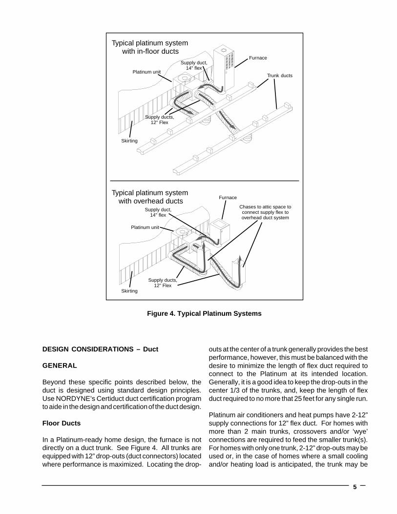
Figure 4. Typical Platinum Systems
Typical platinum system with in-floor ducts
Platinum unit
Furnace
Trunk ducts
Supply ducts,12" Flex
Supply duct,14" flex
Typical platinum system with overhead ducts
Chases to attic space toconnect supply flex tooverhead duct system
Furnace
Platinum unit
Supply ducts,12" Flex
Supply duct,14" flex
Skirting
Skirting
DESIGN CONSIDERATIONS – Duct
GENERAL
Beyond these specific points described below, theduct is designed using standard design principles.Use NORDYNE’s Certiduct duct certification programto aide in the design and certification of the duct design.
Floor Ducts
In a Platinum-ready home design, the furnace is notdirectly on a duct trunk. See Figure 4. All trunks areequipped with 12” drop-outs (duct connectors) locatedwhere performance is maximized. Locating the drop-
outs at the center of a trunk generally provides the bestperformance, however, this must be balanced with thedesire to minimize the length of flex duct required toconnect to the Platinum at its intended location.Generally, it is a good idea to keep the drop-outs in thecenter 1/3 of the trunks, and, keep the length of flexduct required to no more that 25 feet for any single run.
Platinum air conditioners and heat pumps have 2-12”supply connections for 12” flex duct. For homes withmore than 2 main trunks, crossovers and/or ‘wye’connections are required to feed the smaller trunk(s).For homes with only one trunk, 2-12” drop-outs may beused or, in the case of homes where a small coolingand/or heating load is anticipated, the trunk may be

6
designed with only 1-12” drop-out. In this case, theinstaller of the Platinum AC or HP will be required toseal one of the supply connections at the unit using akit available from NORDYNE.
Over-head Ducts
Overhead duct system design for a Platinum-readyhome is the same as a traditional system except thereare no attic cross-overs (in 2-section homes) and astandard down-flow furnace is used. See Figure 4.
The overhead duct system connects to Platinum AC orHP through 12” flex duct that is routed from the attic tobelow the home through chases in each section of thehome. For 3 or more section homes, the additionalsections may be supplied with attic cross-overs or bysplitting the 12” supply lines with “wye” connectorsbelow the home.
It is recommended that the length of flex duct requiredto reach the intended location of the Platinum AC or HPbe included and compressed into the chase forshipment. The Platinum installer can then simply pullthe flex down to make the connection to the Platinumunit.
Alternately, fixed round or rectangular ducts can beused to connect the attic duct system to the bottom ofthe home. In this case, any suitable method may beused as long as the bottom of the duct terminates in a12” round duct connection which can then be used toconnect the Platinum unit.
DESIGN CONSIDERATIONS – Platinum Unit
Although the manufacturer of the home does not installthe Platinum air conditioner or heat pump, it is criticalthat the manufacturer carefully plans for and makescertain arrangements for installation. In the design ofa Platinum-ready home, the intended location of thePlatinum unit is predetermined and communicated tothe retailer. The retailer is not required to install thePlatinum unit in the intended location, but it will be mucheasier than installing it in another location.
It is recommended that the home manufacturer includean outline of the Platinum unit on floor plans to insurethat all involved are aware of the intended location.
OUTSIDE
UNDERHOME
Outside surface of skirting and exterior wall
18"
Platinum 40A Receptacle and Weather-proof cover
From 0" to 12"
34"
72"
PlatinumUnit
Recommended clear zone Critical clear zone
Figure 5. Platinum Location Considerations

7
22"(sm)
26"(lg)
12" (sm)14" (lg)
Platinum Receptacle withWeather-Proof Cover
19" UnderHome
2"
Base Pad
Platinum Cord
14" Inlet
12" Outlet
12" Outlet(opposite side)
Platinum Power Supply
A Platinum-ready home includes a specially designedapproved receptacle and weather-proof cover locatedwithin 12” of the left edge of the intended location of thePlatinum unit. This receptacle is to be located as lowas practical. If the receptacle is mounted as low aspossible – even below floor level – small locationadjustments can be made during Platinum installationif required.
All Platinum units (all sizes and efficiencies) areapproved for installation on a branch circuit using 8-gauge wire protected by a 40-amp circuit breaker. Ina Platinum-ready home, this circuit is supplied by thehome manufacturer.
Power to the Platinum unit is supplied through thiscircuit and connected with a cord set supplied with thePlatinum unit.
Clearance Requirements
The Platinum unit is installed partially under the homeand therefore requires that area to be clear of supports,pipes, drains, traps, service connections, etc. Figure 5shows the areas required to be clear at the intendedlocation of the Platinum unit. Figure 6 shows the sideview of a typical Platinum unit installation. Note that theI-beam is not a problem since the duct can be routedbelow the I-beam if needed.
It is recommended that the home manufacturer markthe intended location of the Platinum unit on the homeand in the set-up instruction to instruct the set-uppersonnel not to place supports or create otherobstructions in that area.
Figure 6. Platinum Location Considerations, Side View

O'Fallon, MO
149B-0801
Specifications and illustrations subject to changewithout notice and without incurring obligations.
Printed in U.S.A. (08/01)

P3B (A,C) Series
• State-of-the-art compressor isstandard equipment.
• Designed using galvanized steelwith a polyester urethane coatfinish. The 950 hour salt sprayfinish resists corrosion 50% betterthan comparable units.
• Both indoor and outdoor coilsare designed to optimize heattransfer, minimize size and cost,and increase durability andreliability.
• A heavy duty PSC motor forlong lasting reliability and
P3BC/Q3BC-12 SEER2 Ton thru 4 Ton UnitsCooling: 24,000 to 46,500 BtuhHeating: 22,800 to 45,600 Btuh (Q3BC only)
Single Packaged Air Conditioner, Single Phase
P3BA/Q3BA-10 SEER2 thru 5 Ton UnitsCooling: 24,000 to 56,000 BtuhHeating: 24,000 to 57,000 Btuh (Q3BA only)
The P3B/Q3B Series single packaged air conditioner/heat pumps are high efficiency self contained cooling andheating units that use the existing furnace to provide airflow and can be installed on a slab. Units are ETL andETLc listed. The unit is truly designed with the contractor and the consumer in mind.
TECHNICALSPECIFICATIONS
• Zero clearance to combustibleson duct side of the unit allows forinstallations in tight areas.
• Easy access to evaporator forcleaning and general mainten-ance.
• Plastic drain pan will never rustand condensate is outside ofhome.
• Compact footprint and profilemake the P3B/Q3B Series easyto install and transport.
• Parts warranty has proven to bea major benefit to the consumer.
operation. Requires no mainten-ance and is completely protectedfrom rain and snow.
• The service valves are easilyaccessible and simplify servicingof the refrigeration system.
• A mesh hail guard that willnever rust protects the coil frombeing damaged by balls,lawnmowers, hail, etc.
• Designed to make servicingeasier for the contractor, accesspanels are provided to all majorcomponents and the compressor.
FEATURES AND BENEFITS
Single Packaged Heat Pump, Single PhaseQ3B(A,C) Series

2
DIMENSIONS
P 3 B A - 024 K
ApplicationP = Air Conditioning Packaged UnitQ = Heat Pump Packaged Unit
Blowerless
Generation 1, 3, Etc.A = 10 SEERC = 12 SEER
Electrical CodeK = 208/230-60-1
Nominal Capacity(000) Btu
MODEL IDENTIFICATION CODE
W
L
SkirtingChannel
EvaporatorAccessPanel
18"
H
Model No.P3B/Q3B- (L) (W) (H)12 Seer Length Width Height
024K 45 34 26030K 45 34 26036K 45 34 26042K 45 34 26048K 45 34 26
Model No.P3B/Q3B- (L) (W) (H)10 Seer Length Width Height
024K 45 28 22030K 45 28 22036K 45 28 22042K 45 34 26048K 45 34 26060K 45 34 26
3
LeftSide View
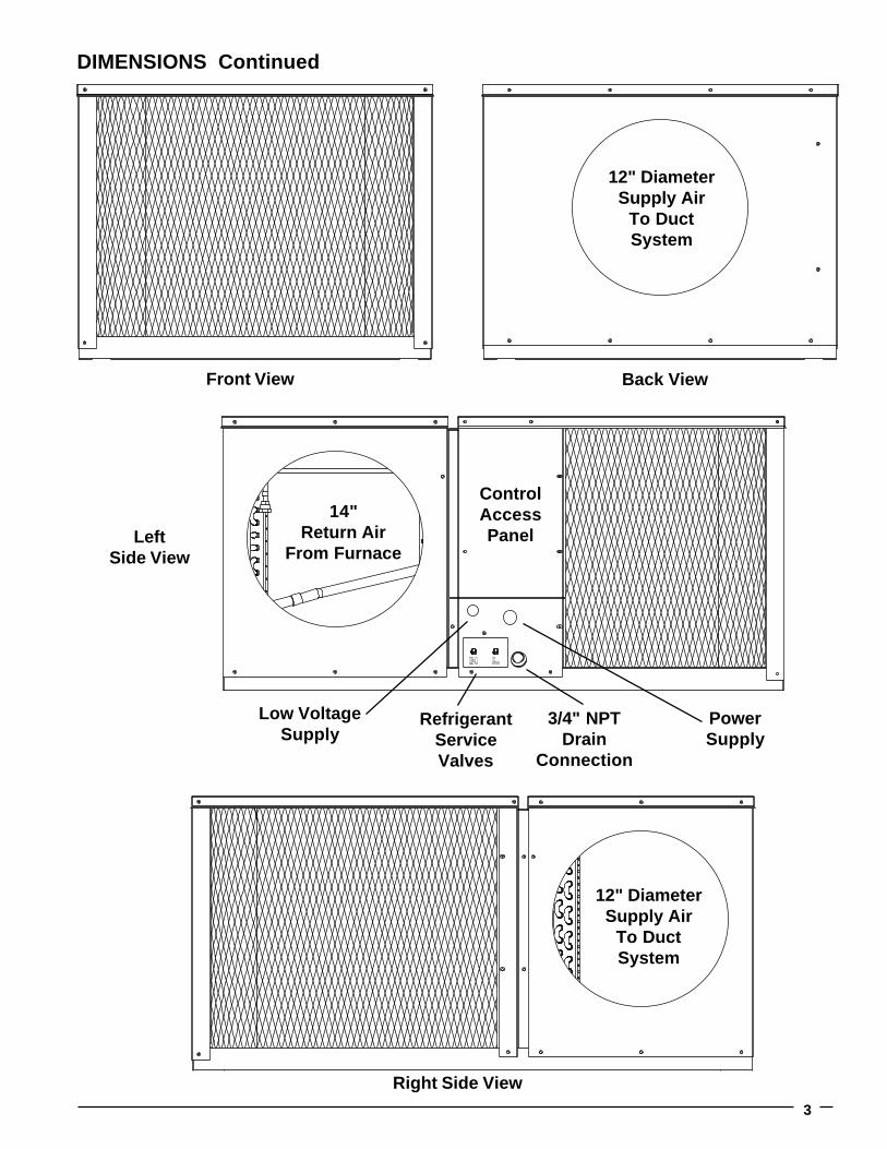
DIMENSIONS Continued
Back ViewFront View
12" DiameterSupply Air
To DuctSystem
14"Return Air
From Furnace
ControlAccessPanel
Low VoltageSupply
RefrigerantServiceValves
3/4" NPTDrain
Connection
PowerSupply
Right Side View
12" DiameterSupply Air
To DuctSystem
4
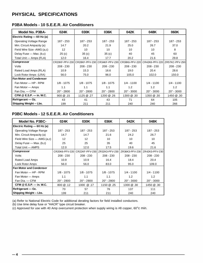
PHYSICAL SPECIFICATIONS
P3BA Models - 10 S.E.E.R. Air Conditioners
P3BC Models - 12 S.E.E.R. Air Conditioners
(a) Refer to National Electric Code for additional derating factors for field installed conductors.(b) Use time delay fuse or "HACR" type circuit breaker.(c) Approved for use with 40 Amp overcurrent protection when supply wiring is #8 copper, 60°c min.
Model No. P3BA- 024K 030K 036K 042K 048K 060KElectric Rating — 60 Hz (a)
Operating Voltage Range 187 - 253 187 - 253 187 - 253 187 - 253 187 - 253 187 - 253
Min. Circuit Ampacity (a) 14.7 20.2 21.9 25.0 26.7 37.0
Field Wire Size -AWG (a,c) 12 10 10 10 10 8
Delay Fuse — Max. (b,c) 25 (c) 35 (c) 35 (c) 40 45 60
Total Unit — Amps (FLA) 12.0 16.4 17.7 20.2 21.6 29.8Compressor CR20KF-PFV-230 CR28KF-PFV-230 CR34KF-PFV-230 CR38K6-PFV-220 CR42K6-PFV-220 ZR57KC-PFV-250
Volts 208 - 230 208 - 230 208 - 230 208 - 230 208 - 230 208 - 230
Rated Load Amps (RLA) 10.9 15.3 16.6 19.0 20.4 28.6
Lock Rotor Amps (LRA) 56.0 75.0 96.0 105.0 102.0 150.0Fan Motor and Condenser
Fan Motor — HP - RPM 1/8 - 1075 1/8 - 1075 1/8 - 1075 1/4 - 1100 1/4 - 1100 1/4 - 1100
Fan Motor — Amps 1.1 1.1 1.1 1.2 1.2 1.2
Fan Dia. — CFM 20" - 2800 20" - 2800 20" - 2800 20" - 3000 20" - 3000 20" - 3000 CFM @ E.S.P. — in. W.C. 900 @ .15 1125 @ .27 1200 @ .26 1300 @ .30 1350 @ .30 1450 @ .30Refrigerant — Oz. 43 41 43 71 64 105Shipping Weight -- Lbs. 199 211 211 240 240 266
Model No. P3BC- 024K 030K 036K 042K 048KElectric Rating — 60 Hz (a)
Operating Voltage Range 187 - 253 187 - 253 187 - 253 187 - 253 187 - 253
Min. Circuit Ampacity (a) 14.7 14.7 21.6 24.2 26.7
Field Wire Size — AWG (a,c) 12 12 10 10 10
Delay Fuse — Max. (b,c) 25 25 35 40 45
Total Unit — AMPS 12.0 12.0 17.5 19.6 21.6Compressor CR20K6-PFV-220 CR22KF-PFV-230 ZR32K3-PFV-230 ZR36K3-PFV-230 ZR42K3-PFV-230
Volts 208 - 230 208 - 230 208 - 230 208 - 230 208 - 230
Rated Load Amps 10.9 10.9 16.4 18.4 20.4
Lock Rotor Amps 56.0 56.0 83.0 95.0 109.0Fan Motor and Condenser
Fan Motor — HP - RPM 1/8 - 1075 1/8 - 1075 1/8 - 1075 1/4 - 1100 1/4 - 1100
Fan Motor — Amps 1.1 1.1 1.1 1.2 1.2
Fan Dia. — CFM 20" - 2800 20" - 2800 20" - 2800 20" - 3000 20" - 3000 CFM @ E.S.P. — in. W.C. 800 @ .12 1000 @ .17 1150 @ .25 1300 @ .30 1450 @ .30Refrigerant — Oz. 70 57 76 137 111Shipping Weight -- Lbs. 199 211 211 240 240
5
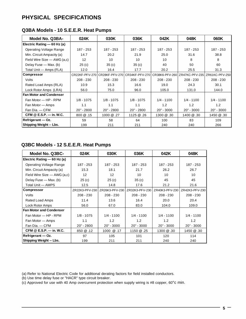
PHYSICAL SPECIFICATIONS
Q3BA Models - 10 S.E.E.R. Heat Pumps
Q3BC Models - 12 S.E.E.R. Heat Pumps
(a) Refer to National Electric Code for additional derating factors for field installed conductors.(b) Use time delay fuse or "HACR" type circuit breaker.(c) Approved for use with 40 Amp overcurrent protection when supply wiring is #8 copper, 60°c min.
Model No. Q3BA- 024K 030K 036K 042K 048K 060KElectric Rating — 60 Hz (a)
Operating Voltage Range 187 - 253 187 - 253 187 - 253 187 - 253 187 - 253 187 - 253
Min. Circuit Ampacity (a) 14.7 20.2 21.9 25.0 31.6 38.8
Field Wire Size — AWG (a,c) 12 10 10 10 8 8
Delay Fuse — Max. (b) 25 (c) 35 (c) 35 (c) 40 50 60
Total Unit — Amps (FLA) 12.0 16.4 17.7 20.2 25.5 31.3Compressor CR22KF-PFV-270 CR28KF-PFV-270 CR34KF-PFV-270 CR38K6-PFV-260 ZR47KC-PFV-235 ZR61KC-PFV-250
Volts 208 - 230 208 - 230 208 - 230 208 - 230 208 - 230 208 - 230
Rated Load Amps (RLA) 10.9 15.3 16.6 19.0 24.3 30.1
Lock Rotor Amps (LRA) 56.0 75.0 96.0 105.0 131.0 144.0Fan Motor and Condenser
Fan Motor — HP - RPM 1/8 - 1075 1/8 - 1075 1/8 - 1075 1/4 - 1100 1/4 - 1100 1/4 - 1100
Fan Motor — Amps 1.1 1.1 1.1 1.2 1.2 1.2
Fan Dia. — CFM 20" - 2800 20" - 2800 20" - 2800 20" - 3000 20" - 3000 20" - 3000 CFM @ E.S.P. — in. W.C. 800 @ .15 1000 @ .27 1125 @ .26 1300 @ .30 1400 @ .30 1450 @ .30Refrigerant — Oz. 59 58 64 100 83 109Shipping Weight -- Lbs. 199 211 211 240 240 266
Model No. Q3BC- 024K 030K 036K 042K 048KElectric Rating — 60 Hz (a)
Operating Voltage Range 187 - 253 187 - 253 187 - 253 187 - 253 187 - 253
Min. Circuit Ampacity (a) 15.3 18.1 21.7 26.2 26.7
Field Wire Size — AWG (a,c) 12 12 10 10 10
Delay Fuse — Max. (b) 25 (c) 25 (c) 35 (c) 45 45
Total Unit — AMPS 12.5 14.8 17.6 21.2 21.6Compressor ZR22K3-PFV-230 ZR26K3-PFV-230 ZR32K3-PFV-230 ZR40K3-PFV-230 ZR42K3-PFV-230
Volts 208 - 230 208 - 230 208 - 230 208 - 230 208 - 230
Rated Load Amps 11.4 13.6 16.4 20.0 20.4
Lock Rotor Amps 56.0 67.0 83.0 104.0 109.0Fan Motor and Condenser
Fan Motor — HP - RPM 1/8 - 1075 1/4 - 1100 1/4 - 1100 1/4 - 1100 1/4 - 1100
Fan Motor — Amps 1.1 1.2 1.2 1.2 1.2
Fan Dia. — CFM 20" - 2800 20" - 3000 20" - 3000 20" - 3000 20" - 3000 CFM @ E.S.P. — in. W.C. 850 @ .12 1000 @ .17 1150 @ .25 1300 @ .30 1450 @ .30Refrigerant — Oz. 97 105 101 120 114Shipping Weight -- Lbs. 199 211 211 240 240

6
SYSTEM HEATING AND COOLING CAPACITIES
ACCESSORIES
Model CoolingNumber Nom. (btuh) SEER
P3BA-024K 24000 10P3BA-030K 30000 10P3BA-036K 36000 10P3BA-042K 42000 10P3BA-048K 46000 10P3BA-060K 56000 10
P3BC-024K 24000 12P3BC-030K 28000 12P3BC-036K 36000 12P3BC-042K 42000 12P3BC-048K 46500 12
P3B(A,C) Series Air ConditionersModel Cooling Heating
Number Nom. (btuh) SEER Nom. (btuh) HSPFQ3BA-024K 24000 10 24000 6.6Q3BA-030K 30000 10 30000 6.6Q3BA-036K 36000 10 33500 6.6Q3BA-042K 41000 10 40500 6.6Q3BA-048K 48000 10 46500 6.6Q3BA-060K 56000 10 57000 6.6
Q3BC-024K 24000 12 22800 7.2Q3BC-030K 30000 12 27500 7.2Q3BC-036K 36000 12 33500 7.2Q3BC-042K 42000 12 42000 7.2Q3BC-048K 46500 12 45600 7.2
Q3B(A,C) Series Heat Pumps
Description Part Number
Plenum Connector, 14" Round (3) 903896
Base Pad, (25" X 25") (13) 903897
Receptacle/Cover Kit, 40A/250V, P/Q3B (12) 903898
Power Cord, P/Q3B (10) 903899
Power Cord, P/Q3B (1) 903973
Single Outlet Kit (6) 903966
Foundation Kit, 90° Duct Connectors 903967
Condensate Drain Kit (12) 903970
Fresh Air Wall Vent 903971
Fresh Air Wall Vent (Ducted) 903974
12"x12"x12" 911470
"Y" Connector with 2 clamps
14"x12"x12" 917963
"Y" Connector with 2 clampsFlex Duct, 12" Round x 25 Ft. 520064
Flex Duct, 12" Round x 18 Ft. 520065
Flex Duct, 14" Round x 25 Ft. 520066
Flex Duct, 14" Round x 18 Ft. 520067Clamps, 10" - 14" diameter 668659

7

O'Fallon, MO
081B-0901 (Replaces 081B-0801)
Before purchasing this appliance, read important energy cost andefficiency information available from your retailer. Specificationsand illustrations subject to change without notice and withoutincurring obligations. Printed in U.S.A. (09/01)
CERTIFICATION APPLIESONLY WHEN THE
COMPLETESYSTEM IS LISTED
WITH ARIR R

VentilAire™ Fresh Air Wall Vent System
Installation Instructions903971 - Through-the-Wall Fresh Air Vent Kit
These instructions are primarily intended to assist qualified individuals experienced in the proper installation of heating and/or air conditioning appliances. Some local codesrequire licensed installation/service personnel for this type of equipment. All installations must be in accordance with these instructions and with all applicable national andlocal codes and standards.
Before beginning the installation, read these instructions thoroughly and follow all warnings and cautions in the instructions and on the unit.
Accommodates Walls From 35/8" to 8" Thick
Kits conform to H.U.D. manufactured home construction and safety standard paragraphs 3280.103(b)(2) for ventilation.
One-Way AirValve Assembly
Air In
Outdoor Facia Plate
Bug Screen
Air Out
Indoor Facia Plate

O'Fallon, MO
7080870
Specifications and illustrations subject to changewithout notice and without incurring obligations.
Printed in U.S.A. (7/01)
DESCRIPTION
The NORDYNE fresh air wall vent system is designedto meet the fresh requirements of the HUD standard,paragraph 3280.103(b)(2), when applied in an outsidewall of a furnace alcove or closet. Exception: This kitis not intended for use in alcove furnace installationswhen the return air path is through the furnace door.
The wall vent system allows fresh air from outside toenter the home by using the negative pressure of theindoor blower in the furnace alcove or closet. It allowsthe passage of air through a highly sensitive valvewhich opens slightly while the blower is operating andcloses under its own weight to avoid drafts.
LOCATION
The VentilAire Fresh Air Wall Vent system MUST belocated in the outside wall of the furnace alcove. It maybe located behind an appliance provided a minimumclearance of 2" is maintained between the applianceand the wall.
NOTE: The actual location of the vent may be subject to otherrules or codes applicable to the home in question. Compliancewith these codes is the responsibility of the installer.
INSTALLATION
Separate the two halves of the vent assembly andremove the extension sleeve. Note: Ignore if one endis marked INSIDE and one OUTSIDE. This applies toanother type application. It is important that theNORDYNE logo is located at the top and the half withthe sensitive flapper valve be located on the outside ofthe home.
1. Drill a pilot hole through the wall from the outside ofthe house, being careful to avoid wall studs or otherobstructions. Next, cut a 41/8" diameter hole throughboth walls.
2. Apply caulking or an appropriate sealant aroundthe base of the tube on the OUTSIDE vent half andinsert it into the wall from the outside (with theextension sleeve taped in place, if needed). Usethe four (4) wood screws provided to secure it tothe wall.
3. From the inside of the house insert the INSIDE venthalf in a similar fashion. Caulking may be omitted,if desired.
Note: The outside sleeve slips into the inside sleeve.
If the wall is between 35/8" and 51/2" in overall thickness,do not use the extension sleeve. Discard it. The sleevemust be used if the wall is between 51/2" and 8" thick.If it is determined that the extension sleeve is needed,slide it into the larger tube stub and tape it in place withduct tape, so that it will overlap the smaller tube stub atleast 1/2" when mounted in the wall.
! WARNING:Disconnect main power supply before drillingthrough the wall. Electrical wiring may be present.
���������7080870

903974 - Through-the-Wall Fresh Air Vent Kit
Installation InstructionsVentilAire™ Fresh Air Wall Vent System
These instructions are primarily intended to assist qualifiedindividuals experienced in the proper installation of heatingand/or air conditioning appliances. Some local codesrequire licensed installation/service personnel for this typeof equipment. All installations must be in accordance withthese instructions and with all applicable national and localcodes and standards.
Before beginning the installation, read these instructionsthoroughly and follow all warnings and cautions in theinstructions and on the unit.
Accommodates Walls From35/8" to 8" ThickKits conform to H.U.D. manufactured homeconstruction and safety standard paragraphs3280.103 (b)(2) for ventilation.
Sheet Metal Screw(For optional mounting location)
Plastic Inlet Fitting with Snap Fits
5" Flex Duct (NORDYNE P/N-917971
sold separately)
Vent Cover
4" - 5" Adapter(6" Long)
Metal Clamp
PlasticClamp
Sheet Metal Mounting Screws for Vent Cover
One-Way Air Valve Assembly
Air In
Outdoor Facia Plate
Air Out
DESCRIPTIONThe NORDYNE fresh air wall vent system is designedfor use in alcove furnace installations when thereturn air path is through the furnace door.
The wall vent system allows fresh air from outside toenter the home by using the negative pressure of theindoor blower.
— INSTALLER —Do Not Discard These Instructions. Aftercompleting the installation, return theseinstructions to the Homeowner’s Package forowner-user’s future reference. Complies withH.U.D. Manufactured Home Construction& Safety Standards.

O'Fallon, MO
7081010
Specifications and illustrations subject to change without notice and without incurring obligations.
Printed in U.S.A. (10/01)
���������708101
LOCATIONThe VentilAire Fresh Air Wall Vent system MUST belocated in the outside wall of the furnace alcove. It maybe located behind an appliance provided a minimumclearance of 2" is maintained between the applianceand the wall.
NOTE: The actual location of the vent may be subjectto other rules or codes applicable to the home inquestion. Compliance with these codes is theresponsibility of the installer.
INSTALLATION
! WARNING:Disconnect main power supply before drillingthrough the wall. Electrical wiring may bepresent.
DO NOT REMOVE THE OVAL KNOCKOUTIN FURNACE TOP BEFORE COMPLETING STEPONE.
1. Determine the location of the plastic inlet fitting.Gas Furnace - Oval knockout located at the top,near the front of the furnace.Air Handler - Oval knockout located on the sides ofthe air handler.Downflow Electric Furnace - Oval knockoutlocated at top near the front of the furnace; or ifusing return air grilles, the plastic fitting may bemounted in the rear of the cabinet over the returnair filter. When using an optional air conditioningcoil it may be mounted to the front or rear coilflange using mounting holes provided. If either ofthese options are selected, DO NOT REMOVEthe oval knockout on the electric furnace. If al-ready removed, the knockout should be resealedto prevent bypass air.Upflow Electric Furnace - a special adaptor(914427) may be applied over the square refriger-ant line knockout.Note: On air handlers, ensure at least3 1/8" clearance is provided on side of unit forspecial duct adaptor kit (914120).
2a.For oval knockout installation, place the plasticinlet fitting with locking tabs onto the sheet metal.The side with tabs further apart (back) should beinserted first, then push gently on the front in thecenter of the part until front tabs fall below the
AdapterKit
Optional A/C Coil
Air Handler Gas Furnace
Electric Furnace
Optional Mounting Holes
sheet metal and release. Part will tighten securelyin place after application of metal clamp.
2b.For optional locations use the sheet metal screwprovided through one of the clearance holes onthe plastic inlet flange.
3. If the wall is between 35/8" and 51/2" in overallthickness, do not use the extension sleeve. Dis-card it. The sleeve should be used if the wall isbetween 51/2" and 8" thick. If it is determined thatthe extension sleeve is needed, slide it into thelarger tube stub and tape it in place with duct tape,so that it will overlap the smaller tube stub at least1/2" when mounted in the wall.Drill a pilot hole through the wall from the outsideof the house, being careful to avoid wall studs orother obstructions. Next, cut a 41/8" diameter holethrough both walls.
4. Apply caulking or an appropriate sealant aroundthe base of the tube on the OUTSIDE vent half andinsert it into the wall from the outside (with theextension sleeve taped in place, if needed). Usethe four (4) wood screws provided to secure it tothe wall.
5. From the inside of the house attach the 5" adaptorhalf in a similar fashion. Caulking may be omitted,if desired.
6. Cut and route the desired length of U.L. approvedClass 1 air duct (NORDYNE P/N-917971) from the5" wall vent to the oval adaptor on the furnace.Secure using clamps provided as shown.

Installation Instructions3 Wire Receptacle/Weatherproof While-In-Use Cover Kit
P3B(A,C) AND Q3B(A,C) Model Series Accessory
PRODUCT DESCRIPTIONRead these instructions thoroughly beforestarting the installation. Follow all precautions,warnings, and applications within theseinstructions.
This kit is specifically designed for applicationon NORDYNE P3B(A,C) or Q3B(A,C) ModelSeries Air Conditioning and Heat Pumpequipment. This receptacle is suitable for abranch circuit rated at 40 Amp, 5 H.P. maximum.
This receptacle must be installed with #8AWG branch circuit wiring and branch circuitovercurrent protection Time Delay Fuse orHACR Type Circuit Breaker rated 40 Ampere.
This receptacle may be used as a discon-necting means per N.E.C. and C.E.C. ONLYwhen used with NORDYNE Plug and CordSet, SKU # 903899.
The weatherproof cover is designed to protectthe plug and receptacle device in “Wet Loca-tions” for “While-In-Use” requirements, and isNEMA 3R rated.
This kit (receptacle, cover, and metal tag) meetsall requirements set forth under N.E.C. Section550-15 (b) and H.U.D. Section 3280.813 (b) forconnection of outdoor heating and/or air condi-tioning equipment.
APPLICATION
! WARNING:This kit is to be installed by an Electrician orqualified service technician in accordance withthese instructions and all codes havingjurisdiction. Failure to follow these instructionscould result in serious injury, property damage,or death. Unless otherwise noted in theseinstructions ONLY factory authorized parts maybe used when modifying this product.
! WARNING:All electrical wiring must comply with thelatest edition of the National Electrical Code(N.E.C.) ANSI/NFPA 70.
! WARNING:RISK OF ELECTRIC SHOCK. Ensure allpower to this circuit is OFF before install-ing. Never wire energized electrical com-ponents.
! CAUTION:USE COPPER CONDUCTORS ONLY.
ASSEMBLY AND WIRING INSTRUCTIONSThe cover must be vertically mounted with thehinge located at the top. This kit also includes agasket to ensure a watertight seal between theback of the cover and smooth mounting surface.Use of additional caulking is recommended onirregular surfaces.
INSTALLER:
PLEASE LEAVE THESEINSTALLATION INSTRUCTIONS
WITH THE HOMEOWNER.

���������7080180O'Fallon, MO
7080180
Specifications and illustrations subject to changewithout notice and without incurring obligations.
Printed in U.S.A. (05/01)
NOTE: See Figure 1 for mounting optionsprior to wiring the receptacle. Cover andreceptacle may be configured differently tomeet installation needs.
1.) Strip conductors using strip gage onreceptacle.DO NOT TIN CONDUCTORS.
2.) Loosen terminal screws. Insert conduc-tors fully into proper terminals perTable 1 and center under terminal screw.
3.) ENSURE THERE ARE NO LOOSESTRANDS.
4.) Tighten terminal screws to 30 lb-in.(3.4 Nm)
5.) Mount receptacle and box with screwsprovided. NOTE: Ground must beoriented to the top as shown.
Table 1
Figure 1. Mounting Options
TERMINAL CONDUCTORGreen, Gnd, G Ground
(Bare, Green orGreen/Yellow
White, W Line(White or Gray)
X, Y, Z or Blank Line(Other Than White (NOT White,or Green) NOT Green)
6.) DO NOT OVER TIGHTEN SCREWS.
7.) Open and close cover lid to ensure properoperation.
8.) The metal tag provided with this kit mustbe permanently affixed to the outsidewall adjacent to the receptacle cover box.Attach the metal tag with screws providedor other equivalent means.
OPTION 1
GASKET
COVER
RECEPTACLE
OUTLET BOX
OPTION 2
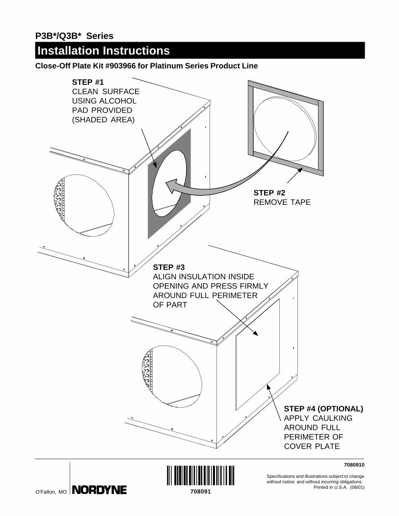
Close-Off Plate Kit #903966 for Platinum Series Product Line
Installation InstructionsP3B*/Q3B* Series
7080910
Specifications and illustrations subject to change without notice and without incurring obligations.
Printed in U.S.A. (08/01)O'Fallon, MO
���������708091
STEP #1CLEAN SURFACEUSING ALCOHOLPAD PROVIDED(SHADED AREA)
STEP #3ALIGN INSULATION INSIDEOPENING AND PRESS FIRMLYAROUND FULL PERIMETEROF PART
STEP #2REMOVE TAPE
STEP #4 (OPTIONAL)APPLY CAULKINGAROUND FULLPERIMETER OFCOVER PLATE
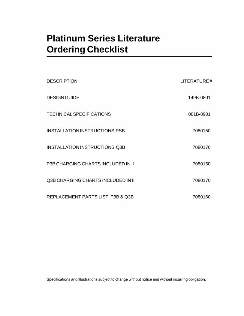
Platinum Series LiteratureOrdering Checklist
DESCRIPTION LITERATURE #
DESIGN GUIDE 149B-0801
TECHNICAL SPECIFICATIONS 081B-0901
INSTALLATION INSTRUCTIONS PSB 7080150
INSTALLATION INSTRUCTIONS Q3B 7080170
P3B CHARGING CHARTS INCLUDED IN II 7080150
Q3B CHARGING CHARTS INCLUDED IN II 7080170
REPLACEMENT PARTS LIST P3B & Q3B 7080160
Specifications and illustrations subject to change without notice and without incurring obligation.

USER'S MANUAL AND INSTALLATIONINSTRUCTIONSP3B (A,C) Series 10 and 12 SEERSingle Package Air Conditioner
IMPORTANTRead this owner information to become familiar with the capabilities and use ofyour appliance. Keep this with literature of other appliances where you have easyaccess to it in the future. If a problem occurs, check the instructions and followrecommendations given. If these suggestions don’t eliminate your problem, callyour installing contractor or distributor in your area.
INTRODUCTIONMost any air conditioner will keep you cool. Our air conditioner was designed todo it efficiently. Efficiency means less cost to you while keeping you comfortable.
WHY YOUR AIR CONDITIONER WORKS SO WELL, SO QUIETLY
1. Air is cooled by a large evaporator coil. Moisture is also removed from the air bythis same coil.
2. Air is then delivered through the main duct, via registers, into your home.
3. Return air is drawn through the return grille.
4. This air enters the unit, passes through the evaporator coil, is cooled and dehumidi-fied. Then the cycle begins again.

2
SECTION 1. OWNERINFORMATION
OPERATING INSTRUCTIONS
To Turn On Air Conditioner
1. Set the system switch to "Cool."2. Set the thermostat at the temperature level
you desire.3. Your air conditioner should start as soon as
room temperature rises above the settingon the thermostat.
To Shut Off Air Conditioner
1. Turn the system switch to "Heat" or "Off."2. Turn the thermostat to the desired heating
temperature setting.
BEFORE YOU CALL A SERVICEMANCheck your system at the start of each airconditioning season. Make sure it's workingright, clean or change filters and make anyneeded adjustments.
In addition, follow these simple rules:1. Never run your system without a filter. If
you do, the cooling coils will collect dirt andmay become clogged.
2. Set your thermostat at the comfort levelyou wish -- and then leave it alone. Let itcontrol the operation of the air conditioningsystem. If you get chilly, turn it up a degreeat a time until comfort is restored.
3. It takes longer for an air conditioner to coolyour dwelling than it does for your furnaceto heat it. So . . . don't turn the unit on andexpect a dramatic drop in temperature, atleast not right away. If your home is hot andhumid, the temperature will drop slowly.
4. Check your filters every 30 days in sum-mer to see if they are dirty. To keep themclean, use a mild solution of detergent andwater on washable types. Replace nonwashable filters.
5. Keep your outdoor condenser coil clean.You can hose it down when it gets dirty.
If your air conditioner isn't working:1. Make sure the fuses are not blown or that
your circuit breakers are on.2. See that your thermostat is set at the
desired temperature and that your system'sswitch is on "Cool."
3. For best air flow, make sure your returngrille is not covered and that the filter isclean.
4. Check the outdoor condenser coil andmake sure it is clean and not clogged withgrass or leaves.
If your air conditioner still isn't working, call yournearest distributor.
SECTION 2. INSTALLERINFORMATION
GENERALRead the following instructions completelybefore performing the installation.These instructions are for the use of qualifiedpersonnel specially trained and experienced inthe installation of this type of equipment andrelated system components. Some states re-quire installation and service personnel to belicensed. Unqualified individuals should notattempt to interpret these instructions or installthis equipment.
The single packaged air conditioners are de-signed for outdoor installation only and can bereadily connected into the high static ductsystem of a home. The only connectionsneeded for installation are the supply and returnducts, the line voltage, and thermostat wiring.
The single package air conditioner is com-pletely assembled, factory wired, and factoryrun tested. The units are ready for easy andimmediate installation.
PRE-INSTALLATION CHECK
Before any installation is attempted, the coolingload of the area to be conditioned must becalculated and a system of the proper capacityselected. It is recommended that the area to beconditioned be completely insulated and vaporsealed.
The installer should comply with all local codesand regulations which govern the installation ofthis type of equipment. Local codes and regu-lations take precedence over any recommen-dations contained in these instructions. Consultlocal building codes and the National ElectricalCode (ANSI CI) for special installation require-ments.
3
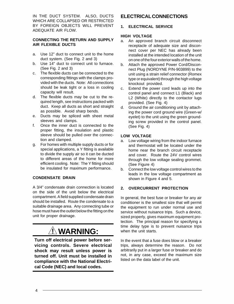
The electrical supply should be checked todetermine if adequate power is available. Ifthere is any question concerning the powersupply, contact the local power company.
Inspecting Equipment: All units are securelypacked at the time of shipment and, uponarrival, should be carefully inspected for dam-age. Claims for damage (apparent or con-cealed) should be filed immediately with thecarrier.
INSTALLATION
(For Platinum Series ready homes)
1. LOCATE THE 40 AMP BRANCH CIR-CUIT DISCONNECT RECEPTACLE ANDDISCONNECT COVER LOCATED OUT-SIDE ON ONE OF THE OUTER WALLSOF THE HOME.
Locate the unit within the reach of the PowerCord assembly and branch circuit receptacle.
• Create a solid, level position, preferably on aconcrete slab or plastic pad (use NORDYNEP/N-903897 or equivalent) and slightly abovegrade level, located where the skirting chan-nel across top of unit is directly under bottomedge of wall. (See Fig. 1)
• Minimum clearances to obstructions. (SeeFig. 1)
2. UNPACK THE UNIT
It is recommended that the unit be unpacked atthe installation site to minimize damage due tohandling.
a. Remove the bands from around the unit.b. Unfold the top and bottom cap flanges.c. Carefully remove the top cap and tube.
! CAUTION:Do not tip the unit on its side. Oil mayenter the compressor cylinders andcause starting trouble. If unit has beenset on its side, restore to upright posi-tion and do not run for several hours.Then run unit for a few seconds. Dothis three or four times with five min-utes between runs.
3. INSTALL THE RETURN AND SUPPLYAIR FITTINGS ON THE UNIT
The supply and return fittings are shipped in thesupply duct. They attach to the unit openingswith a flange and bead arrangement, securedwith two sheet metal screws. Note: For ease ofaccess, install fitting before positioning unit infinal location.
SUPPLY DUCTPosition the supply duct collar so the edge of theunit openings fit between the flange and thebead. Overlap the collar ends keeping the smallscrew holes underneath. Align the holes in thecrimped area and install one screw.
Tap collar as necessary to ensure engagementwith unit opening and install second screw.Tighten first screw.
DUCTING SYSTEM
DUCT REQUIREMENTS
THE AIR OUTPUT OF THE SYSTEM WILLNOT CONDITION THE HOME IF THE AIR ISLOST TO THE OUTSIDE THROUGH LEAKS
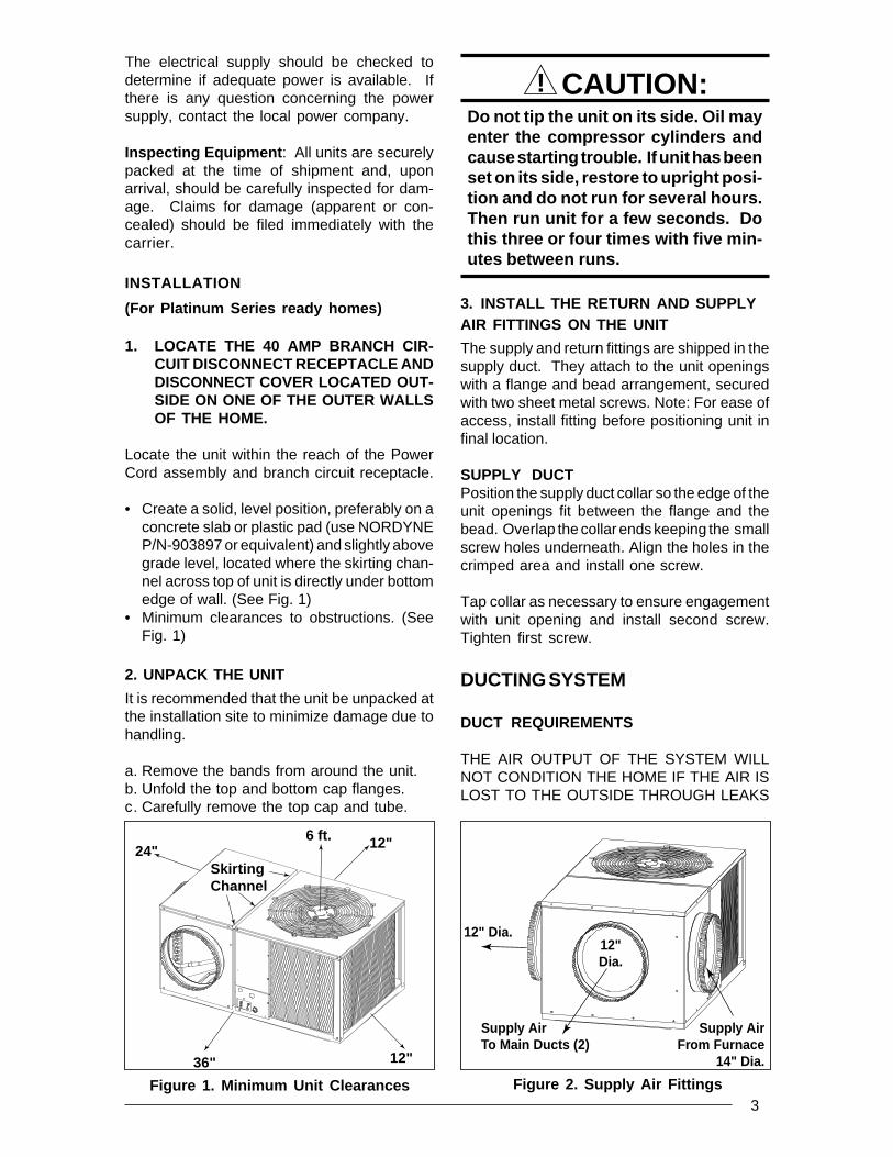
Figure 1. Minimum Unit Clearances Figure 2. Supply Air Fittings
12"36"
24"6 ft. 12"
SkirtingChannel
Supply AirFrom Furnace
14" Dia.
Supply AirTo Main Ducts (2)
12" Dia.12"Dia.
4
IN THE DUCT SYSTEM. ALSO, DUCTSWHICH ARE COLLAPSED OR RESTRICTEDBY FOREIGN OBJECTS WILL PREVENTADEQUATE AIR FLOW.
CONNECTING THE RETURN AND SUPPLYAIR FLEXIBLE DUCTS
a. Use 12” duct to connect unit to the homeduct system. (See Fig. 2 and 3)
b. Use 14” duct to connect unit to furnace.(See Fig. 2 and 3)
c. The flexible ducts can be connected to thecorresponding fittings with the clamps pro-vided with the ducts. Note: All connectionsshould be leak tight or a loss in coolingcapacity will result.
d. The flexible ducts may be cut to the re-quired length, see instructions packed withduct. Keep all ducts as short and straightas possible. Avoid sharp bends.
e. Ducts may be spliced with sheet metalsleeves and clamps.
f. Once the inner duct is connected to theproper fitting, the insulation and plasticsleeve should be pulled over the connec-tion and clamped.
g. For homes with multiple supply ducts or forspecial applications, a Y fitting is availableto divide the supply air so it can be ductedto different areas of the home for moreefficient cooling. Note: The Y fitting shouldbe insulated for maximum performance.
CONDENSATE DRAIN
A 3/4” condensate drain connection is locatedon the side of the unit below the electricalcompartment. A field supplied condensate drainshould be installed. Route the condensate to asuitable drainage area. Any connecting tube orhose must have the outlet below the fitting on theunit for proper drainage.
! WARNING:Turn off electrical power before ser-vicing controls. Severe electricalshock may result unless power isturned off. Unit must be installed incompliance with the National Electri-cal Code (NEC) and local codes.
ELECTRICAL CONNECTIONS
1. ELECTRICAL SERVICE
HIGH VOLTAGEa. An approved branch circuit disconnect
receptacle of adequate size and discon-nect cover per NEC has already beeninstalled at the intended location of the uniton one of the four exterior walls of the home.
b. Attach the approved Power Cord/Discon-nect Plug (NORDYNE P/N-903899) to theunit using a strain relief connector (Romextype or equivalent) through the high voltageknockout provided.
c. Extend the power cord leads up into thecontrol panel and connect L1 (Black) andL2 (White) directly to the contactor lugsprovided. (See Fig. 4)
d. Ground the air conditioning unit by attach-ing the power cord ground wire (Green-w/eyelet) to the unit using the green ground-ing screw provided in the control panel.(See Fig. 4)
LOW VOLTAGEa. Low voltage wiring from the indoor furnace
and thermostat will be located under thehome near the branch circuit receptacleand cover. Route the 24V control wiresthrough the low voltage sealing grommet.(See Figure 4)
b. Connect the low voltage control wires to theleads in the low voltage compartment asshown in Figure 4 and 5.
2. OVERCURRENT PROTECTION
In general, the best fuse or breaker for any airconditioner is the smallest size that will permitthe equipment to run under normal use andservice without nuisance trips. Such a device,sized properly, gives maximum equipment pro-tection. The principal reason for specifying atime delay type is to prevent nuisance tripswhen the unit starts.
In the event that a fuse does blow or a breakertrips, always determine the reason. Do notarbitrarily put in a larger fuse or breaker and donot, in any case, exceed the maximum sizelisted on the data label of the unit.

5
Figure 3. Typical Applications
14" Flex Duct
12" Flex Duct
MULTIPLE DUCT APPLICATION
P3B WITH M1 OR E2 FURNACE INSTALLATION
14" Flex Duct
12" Flex Duct
SINGLE DUCT APPLICATION

6
3. HEAT-COOL THERMOSTAT OPERATION
Heat-Cool Thermostat: Your thermostatshould be located on an inside wall approxi-mately five feet from the floor away from draftsand doors. Do not locate lamps or other objectsnear the thermostat which could affect its op-eration or block a free flow of air.
The heat-cool thermostat is equipped with asystem HEAT-COOL switch, which provides apositive means of preventing simultaneousoperation of the heating and cooling mode. Thethermostat is also equipped with an AUTO-ONfan switch which allows the home owner tooperate the indoor blower when air circulationis desired.
SYSTEM OPERATION
1. PRE-START CHECK LIST
The following check list should be observedprior to starting the unit.
Is the unit level? It should be level or slightlyslanted toward the drain for proper con-densate drainage.
Is there free air flow to and from the con-denser? A one foot clearance around thecoil, and six foot clearance above the fan?
Is the wiring correct according to the wiringdiagram and electrical codes?
Are all the wiring connections tight? Checkthe condenser fan to make sure it turnsfreely.
Is the thermostat wired correctly? Is itinstalled in a proper location?
2. START-UP PROCEDURE
a. Set the system switch to the OFF position.b. Dial thermostat setting as high as it will go.c. Turn on power supply at the circuit breaker.d. Set the system switch to ON or COOL. Set
the temperature setting to below roomtemperature. Verify that the indoor blower,outdoor fan, and compressor are ener-gized and the cooling function starts.
e. Verify that the discharge air grilles areadjusted and the system is balanced.
f. Verify that there are no air leaks in the ductwork.
g. Verify that the condensate drain is properlyinstalled and that it functions correctly.
h. Dial the thermostat higher than room tem-perature. The unit should stop.
i. If using a combination heating-cooling ther-mostat, set to the HEAT position. Proceedto check for correct furnace operation.
j. Verify that the furnace controls and burn-ers or heating elements operate correctly.
k. Instruct the owner on unit operation, filterservicing, and proper thermostat opera-tion.
Figure 5. Low Voltage ConnectionsFigure 4. Power Entry and Hook Up
BLACKC
YELLOWY
FurnaceAir Conditioner
Condensate Drain
LowVoltageEntry
LowVoltageConnections
Ground(Green)
L2 (White) L1 (Black)
ContactorLugs
High Voltage Entry
7
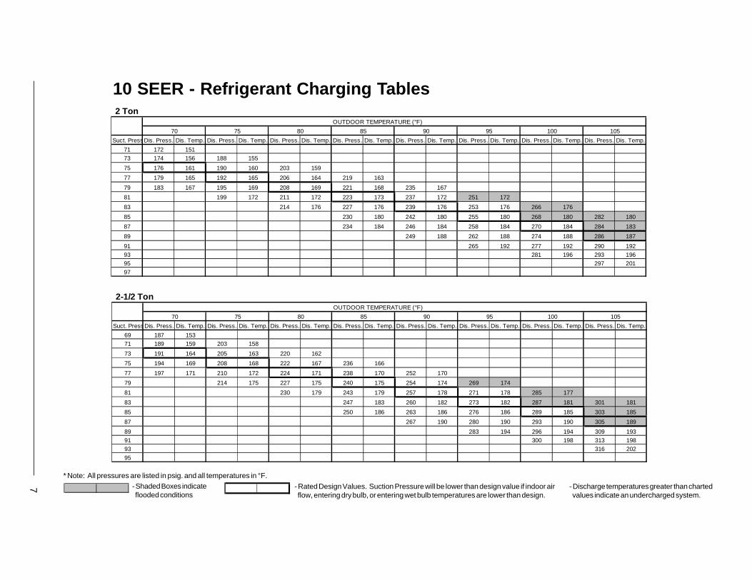
10 SEER - Refrigerant Charging Tables
- Shaded Boxes indicate flooded conditions
* Note: All pressures are listed in psig. and all temperatures in °F.
- Rated Design Values. Suction Pressure will be lower than design value if indoor air flow, entering dry bulb, or entering wet bulb temperatures are lower than design.
- Discharge temperatures greater than charted values indicate an undercharged system.
2 TonOUTDOOR TEMPERATURE (°F)
70 75 80 85 90 95 100 105
Suct. PressDis. Press. Dis. Temp. Dis. Press. Dis. Temp. Dis. Press. Dis. Temp. Dis. Press. Dis. Temp. Dis. Press. Dis. Temp. Dis. Press. Dis. Temp. Dis. Press. Dis. Temp. Dis. Press. Dis. Temp.
71 172 151
73 174 156 188 155
75 176 161 190 160 203 159
77 179 165 192 165 206 164 219 163
79 183 167 195 169 208 169 221 168 235 167
81 199 172 211 172 223 173 237 172 251 172
83 214 176 227 176 239 176 253 176 266 176
85 230 180 242 180 255 180 268 180 282 180
87 234 184 246 184 258 184 270 184 284 183
89 249 188 262 188 274 188 286 187
91 265 192 277 192 290 192
93 281 196 293 196
95 297 201
97
2-1/2 TonOUTDOOR TEMPERATURE (°F)
70 75 80 85 90 95 100 105
Suct. PressDis. Press. Dis. Temp. Dis. Press. Dis. Temp. Dis. Press. Dis. Temp. Dis. Press. Dis. Temp. Dis. Press. Dis. Temp. Dis. Press. Dis. Temp. Dis. Press. Dis. Temp. Dis. Press. Dis. Temp.
69 187 153
71 189 159 203 158
73 191 164 205 163 220 162
75 194 169 208 168 222 167 236 166
77 197 171 210 172 224 171 238 170 252 170
79 214 175 227 175 240 175 254 174 269 174
81 230 179 243 179 257 178 271 178 285 177
83 247 183 260 182 273 182 287 181 301 181
85 250 186 263 186 276 186 289 185 303 185
87 267 190 280 190 293 190 305 189
89 283 194 296 194 309 193
91 300 198 313 198
93 316 202
95

8 10 SEER - Refrigerant Charging Tables
- Shaded Boxes indicate flooded conditions
* Note: All pressures are listed in psig. and all temperatures in °F.
- Rated Design Values. Suction Pressure will be lower than design value if indoor air flow, entering dry bulb, or entering wet bulb temperatures are lower than design.
- Discharge temperatures greater than charted values indicate an undercharged system.
3 TonOUTDOOR TEMPERATURE (°F)
70 75 80 85 90 95 100 105
Suct. PressDis. Press. Dis. Temp. Dis. Press. Dis. Temp. Dis. Press. Dis. Temp. Dis. Press. Dis. Temp. Dis. Press. Dis. Temp. Dis. Press. Dis. Temp. Dis. Press. Dis. Temp. Dis. Press. Dis. Temp.
67 205 167
69 208 172 221 171
71 210 177 223 176 237 175
73 212 182 225 181 239 180 252 179
75 216 185 228 185 241 185 254 184 268 183
77 232 188 244 189 256 188 270 187 283 187
79 247 192 259 192 272 192 285 191 299 190
81 263 196 275 196 287 195 301 194 314 194
83 266 199 278 199 291 199 303 198 316 198
85 282 203 294 203 306 203 318 202
87 297 207 310 207 322 206
89 313 211 325 211
91 329 215
93
3-1/2 TonOUTDOOR TEMPERATURE (°F)
70 75 80 85 90 95 100 105
Suct. PressDis. Press. Dis. Temp. Dis. Press. Dis. Temp. Dis. Press. Dis. Temp. Dis. Press. Dis. Temp. Dis. Press. Dis. Temp. Dis. Press. Dis. Temp. Dis. Press. Dis. Temp. Dis. Press. Dis. Temp.
70 197 157
72 199 162 213 162
74 202 168 216 167 229 167
76 203 174 218 172 232 171 246 171
78 207 177 220 177 234 176 248 176 262 175
80 223 180 236 181 250 180 264 180 278 180
82 240 184 252 184 266 184 280 184 294 184
84 256 188 269 188 282 188 296 188 310 188
86 259 192 272 192 285 192 298 192 312 191
88 276 196 289 196 302 196 314 195
90 292 200 305 200 318 200
92 308 205 321 205
94 325 209
96
9 - Shaded Boxes indicate flooded conditions
* Note: All pressures are listed in psig. and all temperatures in °F.
- Rated Design Values. Suction Pressure will be lower than design value if indoor air flow, entering dry bulb, or entering wet bulb temperatures are lower than design.
- Discharge temperatures greater than charted values indicate an undercharged system.
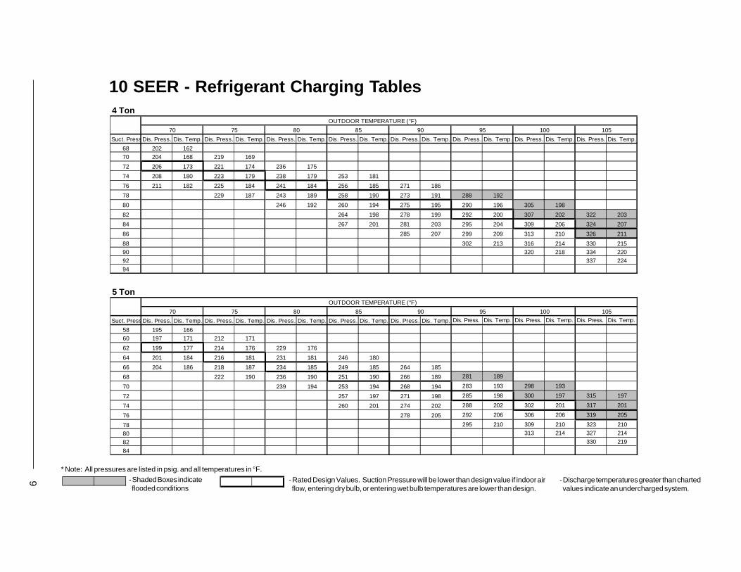
10 SEER - Refrigerant Charging Tables4 Ton
OUTDOOR TEMPERATURE (°F)
70 75 80 85 90 95 100 105
Suct. PressDis. Press. Dis. Temp. Dis. Press. Dis. Temp. Dis. Press. Dis. Temp. Dis. Press. Dis. Temp. Dis. Press. Dis. Temp. Dis. Press. Dis. Temp. Dis. Press. Dis. Temp. Dis. Press. Dis. Temp.
68 202 162
70 204 168 219 169
72 206 173 221 174 236 175
74 208 180 223 179 238 179 253 181
76 211 182 225 184 241 184 256 185 271 186
78 229 187 243 189 258 190 273 191 288 192
80 246 192 260 194 275 195 290 196 305 198
82 264 198 278 199 292 200 307 202 322 203
84 267 201 281 203 295 204 309 206 324 207
86 285 207 299 209 313 210 326 211
88 302 213 316 214 330 215
90 320 218 334 220
92 337 224
94
5 TonOUTDOOR TEMPERATURE (°F)
70 75 80 85 90 95 100 105
Suct. PressDis. Press. Dis. Temp. Dis. Press. Dis. Temp. Dis. Press. Dis. Temp. Dis. Press. Dis. Temp. Dis. Press. Dis. Temp. Dis. Press. Dis. Temp. Dis. Press. Dis. Temp. Dis. Press. Dis. Temp.
58 195 166
60 197 171 212 171
62 199 177 214 176 229 176
64 201 184 216 181 231 181 246 180
66 204 186 218 187 234 185 249 185 264 185
68 222 190 236 190 251 190 266 189 281 189
70 239 194 253 194 268 194 283 193 298 193
72 257 197 271 198 285 198 300 197 315 197
74 260 201 274 202 288 202 302 201 317 201
76 278 205 292 206 306 206 319 205
78 295 210 309 210 323 210
80 313 214 327 214
82 330 219
84

10
- Shaded Boxes indicate flooded conditions
* Note: All pressures are listed in psig. and all temperatures in °F.
- Rated Design Values. Suction Pressure will be lower than design value if indoor air flow, entering dry bulb, or entering wet bulb temperatures are lower than design.
- Discharge temperatures greater than charted values indicate an undercharged system.
12 SEER - Refrigerant Charging Tables 2 Ton
OUTDOOR TEMPERATURE (°F)
70 75 80 85 90 95 100 105
Suct. PressDis. Press. Dis. Temp. Dis. Press. Dis. Temp. Dis. Press. Dis. Temp. Dis. Press. Dis. Temp. Dis. Press. Dis. Temp. Dis. Press. Dis. Temp. Dis. Press. Dis. Temp. Dis. Press. Dis. Temp.
72 163 137
74 165 143 178 141
76 167 148 180 146 192 145
78 170 153 182 151 194 150 207 148
80 173 156 185 156 196 154 209 153 221 152
82 188 159 199 158 211 157 223 156 236 155
84 203 162 214 161 225 160 238 159 250 158
86 217 165 229 164 240 163 252 162 265 161
88 221 169 232 168 243 167 254 166 267 165
90 236 172 247 171 258 170 269 169
92 250 176 261 175 273 174
94 265 179 276 178
96 280 183
98
2-1/2 TonOUTDOOR TEMPERATURE (°F)
70 75 80 85 90 95 100 105
Suct. PressDis. Press. Dis. Temp. Dis. Press. Dis. Temp. Dis. Press. Dis. Temp. Dis. Press. Dis. Temp. Dis. Press. Dis. Temp. Dis. Press. Dis. Temp. Dis. Press. Dis. Temp. Dis. Press. Dis. Temp.
72 168 142
74 171 147 183 147
76 173 152 185 152 198 153
78 175 158 188 157 200 158 213 159
80 178 160 190 162 202 163 215 163 228 164
82 194 165 205 167 217 168 230 168 243 169
84 209 170 220 172 232 173 245 174 258 175
86 224 176 235 177 247 178 260 179 272 180
88 227 179 239 181 250 182 262 183 274 184
90 242 185 254 186 265 187 276 187
92 257 190 269 191 280 192
94 272 196 284 197
96 287 201
98
11 - Shaded Boxes indicate
flooded conditions
* Note: All pressures are listed in psig. and all temperatures in °F.
- Rated Design Values. Suction Pressure will be lower than design value if indoor air flow, entering dry bulb, or entering wet bulb temperatures are lower than design.
- Discharge temperatures greater than charted values indicate an undercharged system.
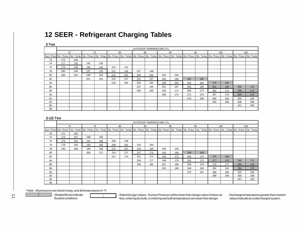
12 SEER - Refrigerant Charging Tables 3 Ton
OUTDOOR TEMPERATURE (°F)
70 75 80 85 90 95 100 105
Suct. PressDis. Press. Dis. Temp. Dis. Press. Dis. Temp. Dis. Press. Dis. Temp. Dis. Press. Dis. Temp. Dis. Press. Dis. Temp. Dis. Press. Dis. Temp. Dis. Press. Dis. Temp. Dis. Press. Dis. Temp.
72 175 128
74 177 133 192 135
76 179 139 195 140 210 141
78 180 148 197 145 212 146 227 148
80 183 151 198 152 214 151 229 152 244 154
82 201 155 215 157 231 157 246 158 262 160
84 219 160 233 162 248 163 264 164 279 165
86 237 165 251 167 266 168 281 169 296 170
88 240 169 255 171 269 172 283 173 298 174
90 258 174 272 176 287 178 300 178
92 276 180 290 182 305 183
94 294 186 308 188
96 311 192
98
3-1/2 TonOUTDOOR TEMPERATURE (°F)
70 75 80 85 90 95 100 105
Suct. PressDis. Press. Dis. Temp. Dis. Press. Dis. Temp. Dis. Press. Dis. Temp. Dis. Press. Dis. Temp. Dis. Press. Dis. Temp. Dis. Press. Dis. Temp. Dis. Press. Dis. Temp. Dis. Press. Dis. Temp.
70 171 152
72 173 157 188 155
74 176 162 191 160 206 158
76 179 165 193 165 208 162 223 160
78 183 168 196 168 210 167 225 165 240 163
80 200 171 214 171 227 170 242 168 258 166
82 217 174 231 173 245 172 260 170 275 169
84 234 177 248 176 262 175 277 173 292 172
86 238 181 251 180 265 179 279 177 294 176
88 255 184 269 183 282 181 296 179
90 272 187 286 185 300 184
92 289 190 303 188
94 307 193
96

- Shaded Boxes indicate flooded conditions
* Note: All pressures are listed in psig. and all temperatures in °F.
- Rated Design Values. Suction Pressure will be lower than design value if indoor air flow, entering dry bulb, or entering wet bulb temperatures are lower than design.
- Discharge temperatures greater than charted values indicate an undercharged system.
12 SEER - Refrigerant Charging Tables4 Ton
OUTDOOR TEMPERATURE (°F)
70 75 80 85 90 95 100 105
Suct. PressDis. Press. Dis. Temp. Dis. Press. Dis. Temp. Dis. Press. Dis. Temp. Dis. Press. Dis. Temp. Dis. Press. Dis. Temp. Dis. Press. Dis. Temp. Dis. Press. Dis. Temp. Dis. Press. Dis. Temp.
64 178 145
66 181 150 194 151
68 183 156 197 156 210 156
70 184 163 199 161 212 161 226 162
72 187 166 200 167 215 166 228 166 242 167
74 204 170 217 171 230 171 244 171 258 172
76 220 174 233 175 246 176 260 176 274 177
78 236 179 249 180 262 180 276 181 289 181
80 240 183 253 184 265 184 278 185 291 185
82 256 188 269 188 282 189 293 189
84 272 193 285 193 298 194
86 289 198 301 198
88 305 203
90
7080150
Specifications and illustrations subject to changew
ithout notice and without incurring obligations.
Printed in U
.S.A
. (4/01)
���������7080150
INS
TALLE
R:
PL
EA
SE
LE
AV
E T
HE
SE
INS
TA
LL
AT
ION
INS
TR
UC
TIO
NS
WIT
H T
HE
HO
ME
OW
NE
R.
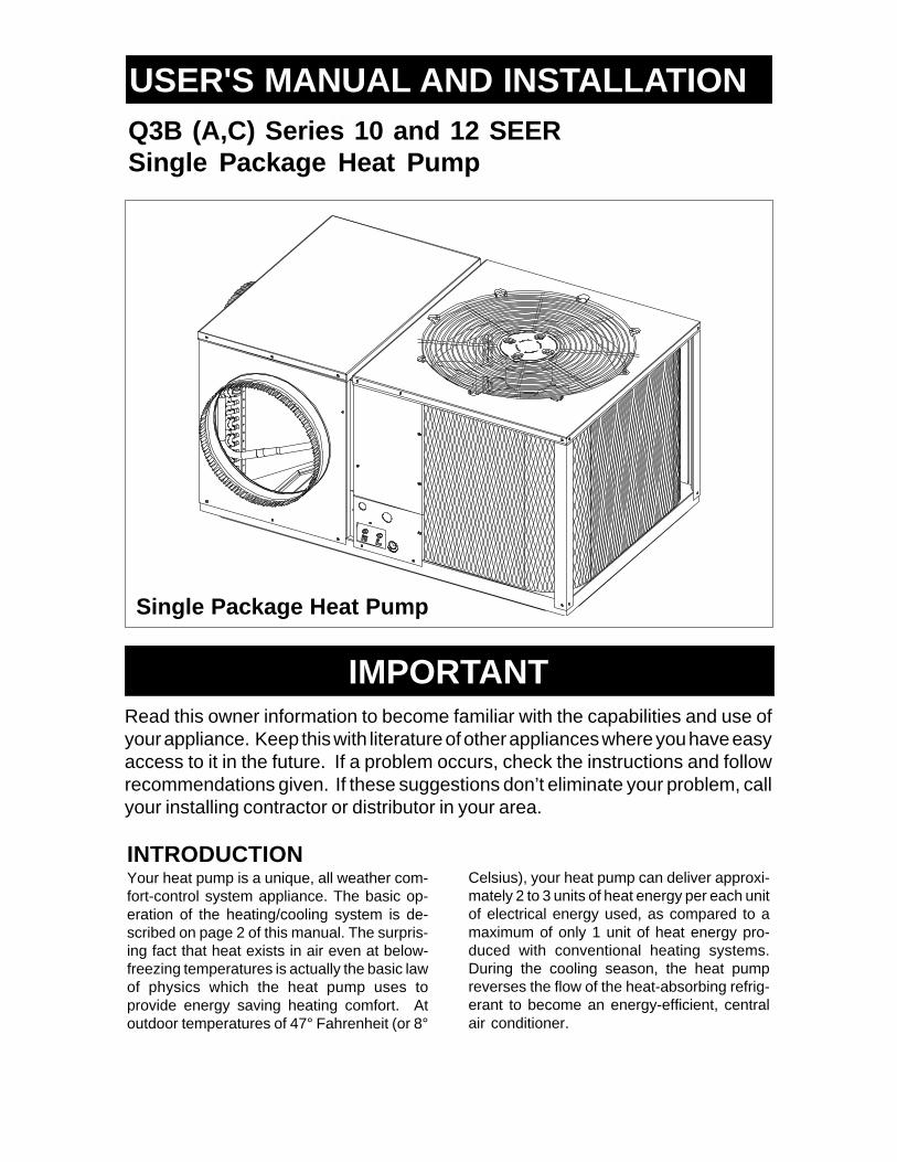
USER'S MANUAL AND INSTALLATIONINSTRUCTIONSQ3B (A,C) Series 10 and 12 SEERSingle Package Heat Pump
INTRODUCTIONYour heat pump is a unique, all weather com-fort-control system appliance. The basic op-eration of the heating/cooling system is de-scribed on page 2 of this manual. The surpris-ing fact that heat exists in air even at below-freezing temperatures is actually the basic lawof physics which the heat pump uses toprovide energy saving heating comfort. Atoutdoor temperatures of 47° Fahrenheit (or 8°
IMPORTANTRead this owner information to become familiar with the capabilities and use ofyour appliance. Keep this with literature of other appliances where you have easyaccess to it in the future. If a problem occurs, check the instructions and followrecommendations given. If these suggestions don’t eliminate your problem, callyour installing contractor or distributor in your area.
Celsius), your heat pump can deliver approxi-mately 2 to 3 units of heat energy per each unitof electrical energy used, as compared to amaximum of only 1 unit of heat energy pro-duced with conventional heating systems.During the cooling season, the heat pumpreverses the flow of the heat-absorbing refrig-erant to become an energy-efficient, centralair conditioner.
Single Package Heat Pump

2
Your heat pump will heat and cool your homeyear round, saving your energy dollars. Duringthe summer, a heat pump performs like anynormal air conditioner. That is, the excess heatenergy inside the home is absorbed by therefrigerant and exhausted outside the home.During the winter months, a heat pump performslike an air conditioner running in reverse. Thatis, available heat energy outside the home isabsorbed by the refrigerant and exhaustedinside the home. This is an efficient heatingmeans because you only pay for “moving” theheat from the outdoors to the indoor area. Youdo not pay to generate the heat, as is the casewith more traditional furnace designs.
OPERATING INSTRUCTIONS
To Operate Your Heat Pump in Cooling —
1. Set the thermostat system switch to COOLand the thermostat fan switch to AUTO.(See Figure 1)
2. Set the thermostat temperature selector tothe desired cooling temperature. The outdoorunit fan, the indoor blower, and the compressorwill all cycle on and off to maintain the indoortemperature at the desired cooling level.
To Shut Off Air Conditioner
1. Turn the system switch to "Heat" or "Off."2. Turn the thermostat to the desired heating
temperature setting.
To Operate Your Heat Pump For Heating —
1. Set the thermostat system switch to HEATand the thermostat fan switch to AUTO.(See Figure 1)
2. Set the thermostat temperature selector tothe desired heating temperature. The outdoorunit fan, the indoor blower, and the compressorwill all cycle on and off to maintain the indoortemperature at the desired heating level.
Defrost — During cold weather heatingoperation, the outdoor unit will develop a coatingof snow and ice on the heat transfer coil. Thisis normal and the unit will periodically defrostitself. During the defrost cycle, the outdoor fanwill stop, while the compressor continues to runand heat the outdoor coil, causing the snow andice to melt. During defrost, there may be somesteam rising from the outdoor unit as the warmcoil causes some melted frost to evaporate.
BEFORE YOU CALL A SERVICEMANCheck your system at the start of each airconditioning season. Make sure it's workingcorrectly, clean or change filters and make anyneeded adjustments.
In addition, follow these simple rules:1. Never run your system without a filter. If
you do, the cooling coils will collect dirt andmay become clogged.
2. Leave thermostat set at the comfort levelyou wish. Let it control the operation of theair conditioning system. If room temp isunsatisfactory, gradually raise the settinguntil comfort is restored.
3. It takes longer for an air conditioner to coolyour dwelling than it does for your furnaceto heat it. So . . . don't turn the unit on andexpect an immediate drop in temperature.If your home is hot and humid, the tempera-ture will drop slowly.
4. Check your filters every 30 days to see ifthey are dirty. To keep them clean, use amild solution of detergent and water onwashable types. Replace non washablefilters.
5. Keep your outdoor condenser coil clean.(You can hose it down when it gets dirty.)
If your air conditioner isn't working:1. Make sure the fuses are not blown or that
your circuit breakers are on.
SECTION 1. OWNER INFORMATION
Figure 1. Typical Heat/Cool Thermostat
FAN SWITCH
TEMPERATURE SELECTOR

3
2. See that your thermostat is set at thedesired temperature and that your system'sswitch is on "Cool."
3. For best air flow, make sure your returngrille is not covered and that the filter isclean.
4. Check the outdoor condenser coil andmake sure it is clean and not clogged withgrass or leaves.
If your air conditioner still isn't working, call yournearest distributor.
SECTION 2. INSTALLERINFORMATION
GENERALRead the following instructions completelybefore performing the installation.These instructions are for the use of qualifiedpersonnel specially trained and experienced inthe installation of this type of equipment andrelated system components. Some states re-quire installation and service personnel to belicensed. Unqualified individuals should notattempt to interpret these instructions or installthis equipment.
The single packaged heat pumps are designedfor outdoor installation only and can be readilyconnected into the high static duct system ofa home. The only connections needed forinstallation are the supply and return ducts, theline voltage, and thermostat wiring.
The single package heat pump is completelyassembled, factory wired, and factory run tested.The units are ready for easy and immediateinstallation.
Use of components other than those specifiedmay invalidate ARI Certification, Code AgencyListing, and limited warranty on the heat pump.
PRE-INSTALLATION CHECK
Before any installation is attempted, the coolingload of the area to be conditioned must becalculated and a system of the proper capacityselected. It is recommended that the area to beconditioned be completely insulated and vaporsealed.
The installer should comply with all local codesand regulations which govern the installation of
this type of equipment. Local codes and regu-lations take precedence over any recommen-dations contained in these instructions. Consultlocal building codes and the National ElectricalCode (ANSI CI) for special installation require-ments.
The electrical supply should be checked todetermine if adequate power is available. Ifthere is any question concerning the powersupply, contact the local power company.
Inspecting Equipment: All units are securelypacked at the time of shipment and, uponarrival, should be carefully inspected for dam-age. Claims for damage (apparent or con-cealed) should be filed immediately with thecarrier.
INSTALLATION
(For Platinum Series ready homes)
1. LOCATE THE 40 AMP BRANCH CIR-CUIT DISCONNECT RECEPTACLE ANDDISCONNECT COVER LOCATED OUT-SIDE ON ONE OF THE OUTER WALLSOF THE HOME.
Locate the unit within the reach of the PowerCord assembly and branch circuit receptacle.
• Create a solid, level position, preferably on aconcrete slab or plastic pad (use NORDYNEP/N-903897 or equivalent) and slightly abovegrade level, located where the skirting chan-nel across top of unit is directly under bottomedge of wall. (See Fig. 2)
• Minimum clearances to obstructions. (SeeFig. 2)
Figure 2. Minimum Unit Clearances
12"36"
24"6 ft. 12"
SkirtingChannel

4
2. UNPACK THE UNIT
It is recommended that the unit be unpacked atthe installation site to minimize damage due tohandling.
a. Remove the bands from around the unit.b. Unfold the top and bottom cap flanges.c. Carefully remove the top cap and tube.
! CAUTION:Do not tip the unit on its side. Oil mayenter the compressor cylinders andcause starting trouble. If unit has beenset on its side, restore to upright posi-tion and do not run for several hours.Then run unit for a few seconds. Dothis three or four times with five min-utes between runs.
3. INSTALL THE RETURN AND SUPPLYAIR FITTINGS ON THE UNIT
The supply and return fittings are shipped in thesupply duct. They attach to the unit openingswith a flange and bead arrangement, securedwith two sheet metal screws. Note: For ease ofaccess, install fitting before positioning unit infinal location.
SUPPLY DUCTPosition the supply duct collar so the edge of theunit openings fit between the flange and thebead. Overlap the collar ends keeping the smallscrew holes underneath. Align the holes in thecrimped area and install one screw.
Tap collar as necessary to ensure engagementwith unit opening and install second screw.Tighten first screw.
DUCTING SYSTEM
DUCT REQUIREMENTS
THE AIR OUTPUT OF THE SYSTEM WILLNOT CONDITION THE HOME IF THE AIR ISLOST TO THE OUTSIDE THROUGH LEAKSIN THE DUCT SYSTEM. ALSO, DUCTSWHICH ARE COLLAPSED OR RESTRICTEDBY FOREIGN OBJECTS WILL PREVENTADEQUATE AIR FLOW.
CONNECTING THE RETURN AND SUPPLYAIR FLEXIBLE DUCTS
a. Use 12” duct to connect unit to the homeduct system. (See Fig. 3 and 4)
b. Use 14” duct to connect unit to furnace.(See Fig. 3 and 4)
c. The flexible ducts can be connected to thecorresponding fittings with clamps (fieldsupplied). Note: All connections should beleak tight or a loss in cooling capacity willresult.
d. The flexible ducts may be cut to the re-quired length, see instructions packed withduct. Keep all ducts as short and straightas possible. Avoid sharp bends.
e. Ducts may be spliced with sheet metalsleeves and clamps.
f. Once the inner duct is connected to theproper fitting, the insulation and plasticsleeve should be pulled over the connec-tion and clamped.
g. For homes with multiple supply ducts or forspecial applications, a Y fitting is availableto divide the supply air so it can be ductedto different areas of the home for moreefficient cooling/heating. Note: The Y fittingshould be insulated for maximum perfor-mance.
CONDENSATE DRAIN
A 3/4” condensate drain connection is locatedon the side of the unit below the electricalcompartment. (See Figure 5). A field suppliedcondensate drain should be installed. Route thecondensate to a suitable drainage area. Anyconnecting tube or hose must have the outletbelow the fitting on the unit for proper drainage.
Figure 3. Supply Air Fittings
Supply AirFrom Furnace
14" Dia.
Supply AirTo Main Ducts (2)
12" Dia.12"Dia.

5
Figure 4. Typical Applications
14" Flex Duct
12" Flex Duct
MULTIPLE DUCT APPLICATION
Q3B WITH M1 OR E2 FURNACE INSTALLATION
14" Flex Duct
12" Flex Duct
SINGLE DUCT APPLICATION

6
! WARNING:Turn off electrical power before ser-vicing controls. Severe electricalshock may result unless power isturned off. Unit must be installed incompliance with the National Electri-cal Code (NEC) and local codes.
ELECTRICAL CONNECTIONS
1. ELECTRICAL SERVICE
HIGH VOLTAGEa. An approved branch circuit disconnect
receptacle of adequate size and discon-nect cover per NEC has already beeninstalled at the intended location of the uniton one of the four exterior walls of the home.
b. Attach the approved Power Cord/Discon-nect Plug (NORDYNE P/N-903899) to theunit using a strain relief connector (Romextype or equivalent) through the high voltageknockout provided.
c. Extend the power cord leads up into thecontrol panel and connect L1 (Black) andL2 (White) directly to the contactor lugsprovided. (See Fig. 5)
d. Ground the heat pump unit by attaching thepower cord ground wire (Green-w/ eyelet)to the unit using the green grounding screwprovided in the control panel. (See Fig. 5)
LOW VOLTAGEa. Low voltage wiring from the indoor furnace
and thermostat will be located under thehome near the branch circuit receptacleand cover. Route the 24V control wiresthrough the low voltage sealing grommet.(See Figure 5)
b. Connect the low voltage control wires to theleads in the low voltage compartment asshown in Figure 5 and 6.
Figure 6. Low Voltage Connections
Figure 5. Power Entry and Hook Up
Condensate Drain
LowVoltageEntry
LowVoltageConnections
Ground(Green)
L2 (White) L1 (Black)
ContactorLugs
High Voltage Entry

7
2. OVERCURRENT PROTECTION
In general, the best fuse or breaker for any airconditioner is the smallest size that will permitthe equipment to run under normal use andservice without nuisance trips. Such a device,sized properly, gives maximum equipment pro-tection. The principal reason for specifying atime delay type is to prevent nuisance tripswhen the unit starts.
In the event that a fuse does blow or a breakertrips, always determine the reason. Do notarbitrarily put in a larger fuse or breaker and donot, in any case, exceed the maximum sizelisted on the data label of the unit.
3. HEAT-COOL THERMOSTAT OPERATION
Heat-Cool Thermostat: Your thermostatshould be located on an inside wall approxi-mately five feet from the floor away from draftsand doors. Do not locate lamps or other objectsnear the thermostat which could affect its op-eration or block a free flow of air.
The heat-cool thermostat is equipped with asystem HEAT-COOL switch, which provides apositive means of preventing simultaneousoperation of the heating and cooling mode. Thethermostat is also equipped with an AUTO-ONfan switch which allows the home owner tooperate the indoor blower when air circulationis desired.
4. DEFROST CYCLE CONTROL
The defrost cycle is initiated via a signal from alow pressure switch located in the outdoor sidereturn gas tubing. This signal indicates the coilpressure has fallen low enough due to the buildup of frost. The defrost cycle will terminate viaa temperature switch located on the outdoor coilafter the frost has been cleared.
5. OUTDOOR THERMOSTAT
The outdoor thermostat (located at the top of thecontrol panel) prevents the auxiliary heat source(gas or electric) from operating above a certainset point. The thermostat is non-adjustable witha factory setting of 40°F.
SYSTEM OPERATION
1. PRE-START CHECK LIST
The following check list should be observedprior to starting the unit.
Is the unit level? It should be level or slightlyslanted toward the drain for proper con-densate drainage.
Is there free air flow to and from the con-denser? A one foot clearance around thecoil, and six foot clearance above the fan?
Is the wiring correct according to the wiringdiagram and electrical codes?
Are all the wiring connections tight? Checkthe condenser fan to make sure it turnsfreely.
Is the thermostat wired correctly? Is itinstalled in a proper location?
2. START-UP PROCEDURE
a. Set the system switch to the OFF position.b. Dial thermostat setting as high as it will go.c. Turn on power supply at the circuit breaker.d. Set the system switch to ON or COOL. Set
the temperature setting to below roomtemperature. Verify that the indoor blower,outdoor fan, and compressor are ener-gized and the cooling function starts.
e. Verify that the discharge air grilles areadjusted and the system is balanced.
f. Verify that there are no air leaks in the ductwork.
g. Verify that the condensate drain is properlyinstalled and that it functions correctly.
h. Dial the thermostat higher than room tem-perature. The unit should stop.
i. Set thermostat to the HEAT position. Pro-ceed to check for correct heat pump op-eration.
j. If outdoor temperature is below 35° F verifythat the furnace controls and burners orheating elements operate correctly.
k. If outdoor temperature is above 35° F youmay jumper out the outdoor thermostat tocheck for proper furnace operation.
l. Instruct the owner on unit operation, filterservicing, and proper thermostat opera-tion.

8 10 SEER - Refrigerant Charging Tables for Heating Mode of Operation
2-1/2 Ton
2 Ton
- Shaded Boxes indicate flooded conditions
* Note: All pressures are listed in psig. and all temperatures in °F.
- Rated Design Values. Suction Pressure will be lower than design value if indoor air flow, entering dry bulb, or entering wet bulb temperatures are lower than design.
- Discharge temperatures greater than charted values indicate an undercharged system.
Pressures shown are for heat pump operating only without back-up heat.
OUTDOOR TEMPERATURE (DEG. F)0 10 20 30 40
Suc. Disch. Disch. Suc. Disch. Disch. Suc. Disch. Disch. Suc. Disch. Disch. Suc. Disch. Disch.Press Press. Temp. Press. Press. Temp. Press. Press. Temp. Press. Press. Temp. Press. Press. Temp.
15 121 132 22 140 136 29 158 140 36 176 144 45 186 155
16 128 130 23 146 134 30 163 138 37 180 142 46 193 15217 135 128 24 151 132 31 168 136 38 184 140 47 200 149
18 142 126 25 157 130 32 172 134 39 187 138 48 207 146
19 149 124 26 163 128 33 177 132 40 191 136 49 214 144
20 156 122 27 169 126 34 182 130 41 195 134 50 221 14121 163 120 28 175 124 35 187 128 42 198 132 51 228 138
50 60
Suc. Disch. Disch. Suc. Disch. Disch.Press. Press. Temp. Press. Press. Temp.
55 209 172 65 233 190
56 216 168 66 240 18357 223 163 67 247 177
58 230 159 68 254 171
59 237 154 69 261 165
60 244 150 70 268 15961 251 145 71 275 153
OUTDOOR TEMPERATURE (DEG. F)0 10 20 30 40
Suc. Disch. Disch. Suc. Disch. Disch. Suc. Disch. Disch. Suc. Disch. Disch. Suc. Disch. Disch.Press Press. Temp. Press. Press. Temp. Press. Press. Temp. Press. Press. Temp. Press. Press. Temp.
16 112 116 24 139 133 32 166 151 40 193 168 48 205 188
17 119 114 25 145 131 33 171 149 41 197 166 49 212 18518 126 112 26 151 129 34 176 147 42 200 164 50 219 182
19 133 110 27 157 127 35 180 145 43 204 162 51 226 179
20 140 108 28 163 125 36 185 143 44 208 160 52 233 176
21 147 106 29 169 123 37 190 141 45 211 158 53 240 17322 154 104 30 174 121 38 195 139 46 215 156 54 247 171
50 60
Suc. Disch. Disch. Suc. Disch. Disch.Press. Press. Temp. Press. Press. Temp.
54 226 209 61 247 231
55 233 205 62 254 22556 240 200 63 261 219
57 247 196 64 268 213
58 254 191 65 275 206
59 261 187 66 282 20060 268 182 67 289 194

9
3-1/2 Ton
3 Ton
10 SEER - Refrigerant Charging Tables for Heating Mode of Operation - Continued
- Shaded Boxes indicate flooded conditions
* Note: All pressures are listed in psig. and all temperatures in °F.
- Rated Design Values. Suction Pressure will be lower than design value if indoor air flow, entering dry bulb, or entering wet bulb temperatures are lower than design.
- Discharge temperatures greater than charted values indicate an undercharged system.
Pressures shown are for heat pump operating only without back-up heat.
OUTDOOR TEMPERATURE (DEG. F)0 10 20 30 40
Suc. Disch. Disch. Suc. Disch. Disch. Suc. Disch. Disch. Suc. Disch. Disch. Suc. Disch. Disch.Press Press. Temp. Press. Press. Temp. Press. Press. Temp. Press. Press. Temp. Press. Press. Temp.
13 121 146 20 137 148 28 153 150 36 169 152 44 172 15614 128 144 21 143 146 29 158 148 37 173 150 45 179 15315 135 142 22 149 144 30 162 146 38 176 148 46 186 15116 142 140 23 154 142 31 167 144 39 180 146 47 193 14817 149 138 24 160 140 32 172 142 40 184 144 48 200 14518 156 136 25 166 138 33 177 140 41 187 142 49 207 14219 163 134 26 172 136 34 182 138 42 191 140 50 214 139
50 60Suc. Disch. Disch. Suc. Disch. Disch.
Press. Press. Temp. Press. Press. Temp.52 185 163 61 198 16953 192 158 62 205 16354 199 154 63 212 15755 206 149 64 219 15156 213 145 65 226 14557 220 140 66 233 13958 227 136 67 240 132
50 60
Suc. Disch. Disch. Suc. Disch. Disch.Press. Press. Temp. Press. Press. Temp.
53 186 196 61 200 224
54 193 191 62 207 21855 200 187 63 214 212
56 207 182 64 221 205
57 214 178 65 228 199
58 221 173 66 235 19359 228 169 67 242 187
OUTDOOR TEMPERATURE (DEG. F)0 10 20 30 40
Suc. Disch. Disch. Suc. Disch. Disch. Suc. Disch. Disch. Suc. Disch. Disch. Suc. Disch. Disch.Press Press. Temp. Press. Press. Temp. Press. Press. Temp. Press. Press. Temp. Press. Press. Temp.
12 127 148 21 141 150 29 155 151 37 169 152 45 172 167
13 134 146 22 147 148 30 160 149 38 173 150 46 179 16414 141 144 23 153 146 31 165 147 39 177 148 47 186 162
15 148 142 24 159 144 32 169 145 40 180 146 48 193 159
16 155 140 25 164 142 33 174 143 41 184 144 49 200 156
17 162 138 26 170 140 34 179 141 42 188 142 50 207 15318 169 136 27 176 138 35 184 139 43 191 140 51 214 150

10
- Shaded Boxes indicate flooded conditions
* Note: All pressures are listed in psig. and all temperatures in °F.
- Rated Design Values. Suction Pressure will be lower than design value if indoor air flow, entering dry bulb, or entering wet bulb temperatures are lower than design.
- Discharge temperatures greater than charted values indicate an undercharged system.
Pressures shown are for heat pump operating only without back-up heat.
10 SEER - Refrigerant Charging Tables for Heating Mode of Operation - Continued
4 Ton
5 Ton
OUTDOOR TEMPERATURE (DEG. F)0 10 20 30 40
Suc. Disch. Disch. Suc. Disch. Disch. Suc. Disch. Disch. Suc. Disch. Disch. Suc. Disch. Disch.Press Press. Temp. Press. Press. Temp. Press. Press. Temp. Press. Press. Temp. Press. Press. Temp.
19 147 139 22 154 138 25 161 137 28 168 135 37 174 15720 154 137 23 160 136 26 166 135 29 172 133 38 181 15421 161 135 24 166 134 27 171 133 30 176 131 39 188 15122 168 133 25 172 132 28 176 131 31 179 129 40 195 14823 175 131 26 178 130 29 180 129 32 183 127 41 202 14524 182 129 27 183 128 30 185 127 33 187 125 42 209 14325 189 127 28 189 126 31 190 125 34 190 123 43 216 140
50 60Suc. Disch. Disch. Suc. Disch. Disch.
Press. Press. Temp. Press. Press. Temp.52 200 201 68 226 24553 207 196 69 233 23954 214 192 70 240 23255 221 187 71 247 22656 228 183 72 254 22057 235 178 73 261 21458 242 174 74 268 208
OUTDOOR TEMPERATURE (DEG. F)0 10 20 30 40
Suc. Disch. Disch. Suc. Disch. Disch. Suc. Disch. Disch. Suc. Disch. Disch. Suc. Disch. Disch.Press Press. Temp. Press. Press. Temp. Press. Press. Temp. Press. Press. Temp. Press. Press. Temp.
11 150 152 15 163 152 20 175 151 25 188 150 35 203 16612 157 150 16 168 150 21 180 149 26 191 148 36 210 16313 164 148 17 174 148 22 185 147 27 195 146 37 217 16014 171 146 18 180 146 23 189 145 28 199 144 38 224 15715 178 144 19 186 144 24 194 143 29 202 142 39 231 15416 185 142 20 192 142 25 199 141 30 206 140 40 238 15117 192 140 21 198 140 26 204 139 31 210 138 41 245 149
50 60Suc. Disch. Disch. Suc. Disch. Disch.
Press. Press. Temp. Press. Press. Temp.51 243 198 66 284 23052 250 193 67 291 22453 257 189 68 298 21854 264 184 69 305 21155 271 180 70 312 20556 278 175 71 319 19957 285 171 72 326 193
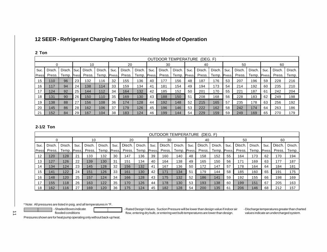
11
12 SEER - Refrigerant Charging Tables for Heating Mode of Operation
2-1/2 Ton
2 Ton
- Shaded Boxes indicate flooded conditions
* Note: All pressures are listed in psig. and all temperatures in °F.
- Rated Design Values. Suction Pressure will be lower than design value if indoor air flow, entering dry bulb, or entering wet bulb temperatures are lower than design.
- Discharge temperatures greater than charted values indicate an undercharged system.
Pressures shown are for heat pump operating only without back-up heat.
OUTDOOR TEMPERATURE (DEG. F)0 10 20 30 40
Suc. Disch. Disch. Suc. Disch. Disch. Suc. Disch. Disch. Suc. Disch. Disch. Suc. Disch. Disch.Press Press. Temp. Press Press. Temp. Press. Press. Temp. Press. Press. Temp. Press. Press. Temp.
15 110 96 23 132 116 32 155 136 40 177 156 48 187 176
16 117 94 24 138 114 33 159 134 41 181 154 49 194 17317 124 92 25 144 112 34 164 132 42 185 152 50 201 170
18 131 90 26 150 110 35 169 130 43 188 150 51 208 168
19 138 88 27 156 108 36 174 128 44 192 148 52 215 165
20 145 86 28 162 106 37 179 126 45 196 146 53 222 16221 152 84 29 167 104 38 183 124 46 199 144 54 229 159
50 60
Suc. Disch. Disch. Suc. Disch. Disch.Press. Press. Temp. Press. Press. Temp.
53 207 196 59 228 216
54 214 192 60 235 21055 221 187 61 242 204
56 228 183 62 249 198
57 235 178 63 256 192
58 242 174 64 263 18659 249 169 65 270 179
OUTDOOR TEMPERATURE (DEG. F)0 10 20 30 40
Suc. Disch. Disch. Suc. Disch. Disch. Suc. Disch. Disch. Suc. Disch. Disch. Suc. Disch. Disch.Press Press. Temp. Press. Press. Temp. Press. Press. Temp. Press. Press. Temp. Press. Press. Temp.
12 120 128 21 133 132 30 147 136 39 160 140 48 158 152
13 127 126 22 139 130 31 151 134 40 164 138 49 165 15014 134 124 23 145 128 32 156 132 41 167 136 50 172 147
15 141 122 24 151 126 33 161 130 42 171 134 51 179 144
16 148 120 25 157 124 34 166 128 43 175 132 52 186 141
17 155 118 26 163 122 35 170 126 44 178 130 53 193 13818 162 116 27 169 120 36 175 124 45 182 128 54 200 135
50 60
Suc. Disch. Disch. Suc. Disch. Disch.Press. Press. Temp. Press. Press. Temp.
55 164 173 62 170 194
56 171 169 63 177 18757 178 164 64 184 181
58 185 160 65 191 175
59 192 155 66 198 169
60 199 151 67 205 16361 206 146 68 212 157
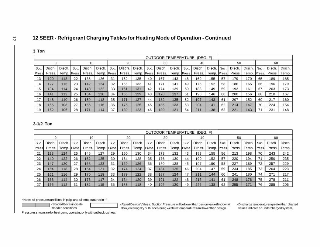
12 12 SEER - Refrigerant Charging Tables for Heating Mode of Operation - Continued
3-1/2 Ton
3 Ton
- Shaded Boxes indicate flooded conditions
* Note: All pressures are listed in psig. and all temperatures in °F.
- Rated Design Values. Suction Pressure will be lower than design value if indoor air flow, entering dry bulb, or entering wet bulb temperatures are lower than design.
- Discharge temperatures greater than charted values indicate an undercharged system.
Pressures shown are for heat pump operating only without back-up heat.
OUTDOOR TEMPERATURE (DEG. F)0 10 20 30 40
Suc. Disch. Disch. Suc. Disch. Disch. Suc. Disch. Disch. Suc. Disch. Disch. Suc. Disch. Disch.Press Press. Temp. Press. Press. Temp. Press. Press. Temp. Press. Press. Temp. Press. Press. Temp.
13 120 118 22 136 126 31 152 135 40 167 143 48 169 155
14 127 116 23 142 124 32 156 133 41 171 141 49 176 15215 134 114 24 148 122 33 161 131 42 174 139 50 183 149
16 141 112 25 154 120 34 166 129 43 178 137 51 190 146
17 148 110 26 159 118 35 171 127 44 182 135 52 197 143
18 155 108 27 165 116 36 175 125 45 185 133 53 204 14119 162 106 28 171 114 37 180 123 46 189 131 54 211 138
50 60
Suc. Disch. Disch. Suc. Disch. Disch.Press. Press. Temp. Press. Press. Temp.
57 179 170 65 189 185
58 186 165 66 196 17959 193 161 67 203 173
60 200 156 68 210 167
61 207 152 69 217 160
62 214 147 70 224 15463 221 143 71 231 148
OUTDOOR TEMPERATURE (DEG. F)0 10 20 30 40
Suc. Disch. Disch. Suc. Disch. Disch. Suc. Disch. Disch. Suc. Disch. Disch. Suc. Disch. Disch.Press Press. Temp. Press. Press. Temp. Press. Press. Temp. Press. Press. Temp. Press. Press. Temp.
21 133 124 25 146 127 29 160 130 34 173 132 43 183 155
22 140 122 26 152 125 30 164 128 35 176 130 44 190 15223 147 120 27 158 123 31 169 126 36 180 128 45 197 150
24 154 118 28 164 121 32 174 124 37 184 126 46 204 147
25 161 116 29 170 119 33 179 122 38 187 124 47 211 144
26 168 114 30 176 117 34 184 120 39 191 122 48 218 14127 175 112 31 182 115 35 188 118 40 195 120 49 225 138
50 60
Suc. Disch. Disch. Suc. Disch. Disch.Press. Press. Temp. Press. Press. Temp.
56 213 198 70 243 242
57 220 194 71 250 23558 227 189 72 257 229
59 234 185 73 264 223
60 241 180 74 271 217
61 248 176 75 278 21162 255 171 76 285 205
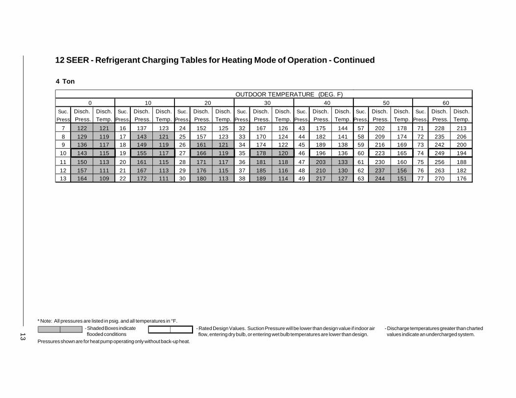
13
12 SEER - Refrigerant Charging Tables for Heating Mode of Operation - Continued
4 Ton
- Shaded Boxes indicate flooded conditions
* Note: All pressures are listed in psig. and all temperatures in °F.
- Rated Design Values. Suction Pressure will be lower than design value if indoor air flow, entering dry bulb, or entering wet bulb temperatures are lower than design.
- Discharge temperatures greater than charted values indicate an undercharged system.
Pressures shown are for heat pump operating only without back-up heat.
OUTDOOR TEMPERATURE (DEG. F)0 10 20 30 40
Suc. Disch. Disch. Suc. Disch. Disch. Suc. Disch. Disch. Suc. Disch. Disch. Suc. Disch. Disch.Press Press. Temp. Press. Press. Temp. Press. Press. Temp. Press. Press. Temp. Press. Press. Temp.
7 122 121 16 137 123 24 152 125 32 167 126 43 175 144
8 129 119 17 143 121 25 157 123 33 170 124 44 182 1419 136 117 18 149 119 26 161 121 34 174 122 45 189 138
10 143 115 19 155 117 27 166 119 35 178 120 46 196 136
11 150 113 20 161 115 28 171 117 36 181 118 47 203 133
12 157 111 21 167 113 29 176 115 37 185 116 48 210 13013 164 109 22 172 111 30 180 113 38 189 114 49 217 127
50 60
Suc. Disch. Disch. Suc. Disch. Disch.Press. Press. Temp. Press. Press. Temp.
57 202 178 71 228 213
58 209 174 72 235 20659 216 169 73 242 200
60 223 165 74 249 194
61 230 160 75 256 188
62 237 156 76 263 18263 244 151 77 270 176
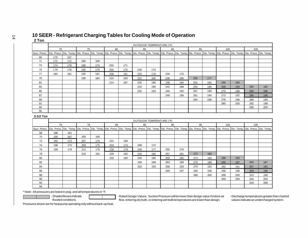
14 10 SEER - Refrigerant Charging Tables for Cooling Mode of Operation
2 TonOUTDOOR TEMPERATURE (°F)
70 75 80 85 90
Suct. Press. Dis. Press. Dis. Temp. Dis. Press. Dis. Temp. Dis. Press. Dis. Temp. Dis. Press. Dis. Temp. Dis. Press. Dis. Temp.
69 170 167
71 172 172 186 169
73 174 178 188 174 202 171
75 179 178 190 179 204 176 218 173
77 183 181 195 181 206 181 220 178 234 175
79 198 184 210 183 222 182 236 180
81 214 187 226 186 238 184
83 229 189 242 188
85 233 193 245 192
87 249 196
89
91
93
95
95 100 105
Dis. Press. Dis. Temp. Dis. Press. Dis. Temp. Dis. Press. Dis. Temp.
250 177
252 182 266 180
254 186 268 184 282 182
257 190 270 188 284 186
261 194 273 192 286 190
264 198 276 196 289 194
280 200 292 198
295 203
2-1/2 TonOUTDOOR TEMPERATURE (°F)
70 75 80 85 90
Suct. Press. Dis. Press. Dis. Temp. Dis. Press. Dis. Temp. Dis. Press. Dis. Temp. Dis. Press. Dis. Temp. Dis. Press. Dis. Temp.
68 188 161
70 190 167 205 165
72 192 172 207 170 221 169
74 196 175 209 175 224 174 238 172
76 199 178 212 178 226 178 240 177 255 176
78 216 181 229 182 242 182 257 181
80 233 185 246 185 259 185
82 249 189 263 189
84 253 193 266 193
86 269 197
88
90
92
94
95 100 105
Dis. Press. Dis. Temp. Dis. Press. Dis. Temp. Dis. Press. Dis. Temp.
272 180
274 184 288 183
276 188 290 187 305 187
279 192 292 191 307 191
283 196 296 196 309 195
286 200 299 200 313 199
303 204 316 204
319 208
- Shaded Boxes indicate flooded conditions
* Note: All pressures are listed in psig. and all temperatures in °F.
- Rated Design Values. Suction Pressure will be lower than design value if indoor air flow, entering dry bulb, or entering wet bulb temperatures are lower than design.
- Discharge temperatures greater than charted values indicate an undercharged system.
Pressures shown are for heat pump operating only without back-up heat.

15
3 TonOUTDOOR TEMPERATURE (°F)
70 75 80 85 90
Suct. Press. Dis. Press. Dis. Temp. Dis. Press. Dis. Temp. Dis. Press. Dis. Temp. Dis. Press. Dis. Temp. Dis. Press. Dis. Temp.
67 196 160
69 199 165 213 165
71 201 170 215 170 229 171
73 202 179 217 175 231 176 245 176
75 205 181 218 182 233 180 247 180 261 181
77 222 185 235 186 249 185 263 185
79 238 189 251 189 265 189
81 255 193 268 194
83 258 197 271 197
85 275 201
8789
91
93
95 100 105
Dis. Press. Dis. Temp. Dis. Press. Dis. Temp. Dis. Press. Dis. Temp.
277 185
279 190 293 190
281 194 295 194 309 194
284 198 297 198 311 198
288 202 301 202 313 202
291 206 304 206 317 207308 211 321 211
324 216
3-1/2 TonOUTDOOR TEMPERATURE (°F)
70 75 80 85 90
Suct. Press. Dis. Press. Dis. Temp. Dis. Press. Dis. Temp. Dis. Press. Dis. Temp. Dis. Press. Dis. Temp. Dis. Press. Dis. Temp.
70 207 162
72 209 168 223 168
74 211 173 225 173 238 173
76 211 183 227 178 240 178 254 178
78 215 186 227 186 242 183 256 182 269 182
80 231 189 244 189 258 187 271 187
82 247 192 260 192 273 191
84 263 195 276 195
86 267 199 279 199
88 283 203
90
92
94
96
95 100 105
Dis. Press. Dis. Temp. Dis. Press. Dis. Temp. Dis. Press. Dis. Temp.
284 187
286 191 300 191
289 195 302 195 315 195
292 199 304 199 317 198
295 203 308 203 319 202
299 207 311 208 324 207
315 212 327 212
331 216
- Shaded Boxes indicate flooded conditions
* Note: All pressures are listed in psig. and all temperatures in °F.
- Rated Design Values. Suction Pressure will be lower than design value if indoor air flow, entering dry bulb, or entering wet bulb temperatures are lower than design.
- Discharge temperatures greater than charted values indicate an undercharged system.
10 SEER - Refrigerant Charging Tables for Cooling Mode of Operation - Continued
Pressures shown are for heat pump operating only without back-up heat.

16 10 SEER - Refrigerant Charging Tables for Cooling Mode of Operation - Continued
4 TonOUTDOOR TEMPERATURE (°F)
70 75 80 85 90
Suct. Press. Dis. Press. Dis. Temp. Dis. Press. Dis. Temp. Dis. Press. Dis. Temp. Dis. Press. Dis. Temp. Dis. Press. Dis. Temp.
65 200 140
67 202 146 218 150
69 204 151 220 155 236 159
71 204 162 222 160 239 164 255 168
73 207 165 223 168 241 169 257 172 273 176
75 226 171 242 175 259 177 275 181
77 245 178 261 182 277 185
79 264 185 280 189
81 268 189 283 193
83 287 197
85
87
8991
95 100 105
Dis. Press. Dis. Temp. Dis. Press. Dis. Temp. Dis. Press. Dis. Temp.
291 185
293 189 309 192
295 193 311 196 327 200
299 197 313 200 329 204
302 201 318 205 331 208
306 205 321 209 337 213
325 213 340 218
343 222
5 TonOUTDOOR TEMPERATURE (°F)
70 75 80 85 90
Suct. Press. Dis. Press. Dis. Temp. Dis. Press. Dis. Temp. Dis. Press. Dis. Temp. Dis. Press. Dis. Temp. Dis. Press. Dis. Temp.
56 188 14358 190 148 205 151
60 193 154 207 156 222 159
62 193 163 210 161 225 163 239 166
64 196 166 210 168 227 168 242 171 256 173
66 214 171 228 174 244 175 259 178
68 232 177 246 180 261 182
70 249 184 263 186
72 253 187 267 190
74 270 194
76
78
80
82
95 100 105
Dis. Press. Dis. Temp. Dis. Press. Dis. Temp. Dis. Press. Dis. Temp.
274 180
276 184 290 187
278 189 292 191 307 193
281 193 294 195 309 197
284 197 299 199 311 201
288 201 302 204 316 206
305 208 320 211
323 215
- Shaded Boxes indicate flooded conditions
* Note: All pressures are listed in psig. and all temperatures in °F.
- Rated Design Values. Suction Pressure will be lower than design value if indoor air flow, entering dry bulb, or entering wet bulb temperatures are lower than design.
- Discharge temperatures greater than charted values indicate an undercharged system.
Pressures shown are for heat pump operating only without back-up heat.

17
12 SEER - Refrigerant Charging Tables for Cooling Mode of Operation 2 Ton
OUTDOOR TEMPERATURE (°F)
70 75 80 85 90
Suct. Press. Dis. Press. Dis. Temp. Dis. Press. Dis. Temp. Dis. Press. Dis. Temp. Dis. Press. Dis. Temp. Dis. Press. Dis. Temp.
73 176 98
75 178 103 190 108
77 180 109 192 113 203 118
79 180 120 194 118 206 123 217 128
81 183 123 194 127 208 128 219 132 231 137
83 198 130 209 134 221 137 233 141
85 212 137 223 142 235 146
87 227 146 238 150
89 230 149 241 154
91 244 158
93
95
97
99
95 100 105
Dis. Press. Dis. Temp. Dis. Press. Dis. Temp. Dis. Press. Dis. Temp.
244 146
246 150 258 155
249 154 260 159 271 163
252 158 262 163 273 167
255 163 266 167 275 171
259 167 270 171 281 176
273 176 284 181
287 185
2-1/2 TonOUTDOOR TEMPERATURE (°F)
70 75 80 85 90
Suct. Press. Dis. Press. Dis. Temp. Dis. Press. Dis. Temp. Dis. Press. Dis. Temp. Dis. Press. Dis. Temp. Dis. Press. Dis. Temp.
75 187 124
77 189 129 203 133
79 191 135 205 138 218 141
81 192 143 207 143 221 146 234 149
83 196 146 208 149 223 151 236 154 250 157
85 212 152 224 156 238 158 252 161
87 228 159 241 163 254 166
89 244 166 257 170
91 248 170 260 174
93 264 178
95
97
99
101
95 100 105
Dis. Press. Dis. Temp. Dis. Press. Dis. Temp. Dis. Press. Dis. Temp.
266 165
268 169 281 172
270 173 283 176 297 180
273 177 285 180 299 183
276 181 289 185 301 187
280 185 293 189 305 192
296 193 309 197
312 201
- Shaded Boxes indicate flooded conditions
* Note: All pressures are listed in psig. and all temperatures in °F.
- Rated Design Values. Suction Pressure will be lower than design value if indoor air flow, entering dry bulb, or entering wet bulb temperatures are lower than design.
- Discharge temperatures greater than charted values indicate an undercharged system.
Pressures shown are for heat pump operating only without back-up heat.

18 12 SEER - Refrigerant Charging Tables for Cooling Mode of Operation - Continued
3 TonOUTDOOR TEMPERATURE (°F)
70 75 80 85 90
Suct. Press. Dis. Press. Dis. Temp. Dis. Press. Dis. Temp. Dis. Press. Dis. Temp. Dis. Press. Dis. Temp. Dis. Press. Dis. Temp.
71 183 13573 186 140 201 142
75 188 145 203 147 218 148
77 188 156 205 152 220 153 235 155
79 191 158 206 160 222 158 238 159 253 161
81 209 163 224 164 240 164 255 165
83 227 167 242 169 257 170
85 245 172 259 174
87 248 176 263 178
89 266 182
9193
9597
95 100 105
Dis. Press. Dis. Temp. Dis. Press. Dis. Temp. Dis. Press. Dis. Temp.
270 167
272 171 287 172
274 175 289 176 304 178
277 179 291 180 306 182
281 183 295 185 308 185
284 187 299 189 313 191302 193 316 195
320 200
3-1/2 TonOUTDOOR TEMPERATURE (°F)
70 75 80 85 90
Suct. Press. Dis. Press. Dis. Temp. Dis. Press. Dis. Temp. Dis. Press. Dis. Temp. Dis. Press. Dis. Temp. Dis. Press. Dis. Temp.
71 171 138
73 173 143 189 144
75 176 148 192 149 207 150
77 177 156 194 154 210 155 225 156
79 180 159 195 160 212 160 228 160 244 161
81 199 163 214 165 230 165 246 166
83 217 168 232 169 248 170
85 236 173 251 174
87 239 177 254 178
89 258 182
91
93
95
97
95 100 105
Dis. Press. Dis. Temp. Dis. Press. Dis. Temp. Dis. Press. Dis. Temp.
262 167
264 171 279 172
266 175 281 176 297 177
269 179 283 180 299 181
272 183 287 184 301 185
276 187 291 189 306 190
294 193 309 194
313 199
- Shaded Boxes indicate flooded conditions
* Note: All pressures are listed in psig. and all temperatures in °F.
- Rated Design Values. Suction Pressure will be lower than design value if indoor air flow, entering dry bulb, or entering wet bulb temperatures are lower than design.
- Discharge temperatures greater than charted values indicate an undercharged system.
Pressures shown are for heat pump operating only without back-up heat.

19
12 SEER - Refrigerant Charging Tables for Cooling Mode of Operation - Continued
4 TonOUTDOOR TEMPERATURE (°F)
70 75 80 85 90
Suct. Press. Dis. Press. Dis. Temp. Dis. Press. Dis. Temp. Dis. Press. Dis. Temp. Dis. Press. Dis. Temp. Dis. Press. Dis. Temp.
68 170 138
70 172 144 187 145
72 175 149 189 150 204 152
74 175 158 191 155 206 157 221 158
76 178 161 192 163 208 162 223 163 237 165
78 196 166 209 167 225 168 239 169
80 213 171 227 172 242 174
82 230 176 244 178
84 234 180 248 182
86 251 185
88
90
92
94
95 100 105
Dis. Press. Dis. Temp. Dis. Press. Dis. Temp. Dis. Press. Dis. Temp.
254 171
256 175 271 176
258 179 273 180 287 182
262 183 275 184 289 186
265 187 279 189 291 190
268 191 282 193 296 195
286 197 300 199
303 204
- Shaded Boxes indicate flooded conditions
* Note: All pressures are listed in psig. and all temperatures in °F.
- Rated Design Values. Suction Pressure will be lower than design value if indoor air flow, entering dry bulb, or entering wet bulb temperatures are lower than design.
- Discharge temperatures greater than charted values indicate an undercharged system.
Pressures shown are for heat pump operating only without back-up heat.

7080170
Specifications and illustrations subject to changewithout notice and without incurring obligations.
Printed in U.S.A. (6/01)
���������7080170
INSTALLER
PLEASE LEAVE THESEINSTALLATION INSTRUCTIONS
WITH THE HOMEOWNER.

REPLACEMENT PARTS LISTSingle Package Air Conditioner and Heat Pump
P3B (A,C) and Q3B (A,C) Series10 SEER and 12 SEER Models


3
10 and 12 SEER Single Package Air ConditionerModel P3B(A,C)
Item Part # Description -024 -030 -036 -042 -048 -060 -024 -030 -036 -042 -048
917501 917502 917503 917504 917505 917506 917511 917512 917513 917514 917515
1 669175 Grille, Outdoor Fan 1 1 1 1 1 1 1 1 1 1 1
2 621925 Motor, Outdoor Fan - 208/230, 1/8 HP 1 1 1 1 1
621926 Motor, Outdoor Fan - 208/230, 1/4 HP 1 1 1 1 1 1
3 667279 Fan Blade - 3 Blade, 20", 26 Deg. 1 1 1 1 1 1
667278 Fan Blade - 3 Blade, 20", 30 Deg. 1 1 1 1 1
4 D01181 Pan, Condenser Top 1 1 1
D01182 Pan, Condenser Top 1 1 1 1 1 1 1 1
5 391871 Panel, Condenser End 1 1 1
391872 Panel, Condenser End 1 1 1 1 1 1 1 1
6 391861R Panel, Divider w/Insulation 1 1 1
391862R Panel, Divider w/Insulation 1 1 1 1 1 1 1 1
7 N/A
8 N/A
9 913319 Compressor, CR20K6 1 1
912957 Compressor, CR28K6 1
914955 Compressor, CR34K6 1
912958 Compressor, CR38K6 1
912959 Compressor, CR42K6 1
914749 Compressor, ZR57KC 1
912956 Compressor, CR22K6 1
914927 Compressor, ZR32K3 1
917861 Compressor, ZR36K3 1
917243 Compressor, ZR42K3 1
10 D09991 Brace, Corner 2 2 2
D09992 Brace, Corner 2 2 2 2 2 2 2 2
11 N/A
12 N/A
13 N/A
14 N/A
Replacement Parts List P3BA Series (10 SEER Package A/C) P3BC Series (12 SEER Package A/C)
15 D11851R Outdoor Coil Assy w/ Hail Guard 1
D11852R Outdoor Coil Assy w/ Hail Guard 1
D11853R Outdoor Coil Assy w/ Hail Guard 1
D11854R Outdoor Coil Assy w/ Hail Guard 1 1 1 1 1
D12112R Outdoor Coil Assy w/ Hail Guard 1 1 1
16 391811R Pan, Bottom w/Insulation 1 1 1
391812R Pan, Bottom w/Insulation 1 1 1 1 1 1 1 1
17 N/A
18 N/A
19 N/A
20 268091 Bracket, Service Port 1 1 1 1 1 1 1 1 1 1 1
21 391931 Panel, Electrical 1 1 1 1 1 1 1 1 1 1 1
22 391941 Cover, Control Panel 1 1 1
391942 Cover, Control Panel 1 1 1 1 1 1 1 1
23 663871 Pipe, Condensate Drain, Evap. 1 1 1 1 1 1 1 1 1 1 1
24 663860 Pipe, Condensate Drain, Cond. 1 1 1 1 1 1 1 1 1 1 1
25 669354 Pan, Condensate Drain 1 1 1
669353 Pan, Condensate Drain 1 1 1 1 1 1 1 1
26 250102 Collar, Duct 14" 1 1 1 1 1 1 1 1 1 1 1
27 D11891R Panel, Evaporator End w/Insulation 1 1 1
D11892R Panel, Evaporator End w/Insulation 1 1 1 1 1 1 1 1
28 250101 Collar, Duct 12" 2 2 2 2 2 2 2 2 2 2 2

4
10 and 12 SEER Single Package Air ConditionerModel P3B(A,C)
33 D12062R Indoor Coil Assy w/Distributor Assy. 1
D12061R Indoor Coil Assy w/Distributor Assy. 1 1
D12072R Indoor Coil Assy w/Distributor Assy. 1 1
D12074R Indoor Coil Assy w/Distributor Assy. 1 1
D12073R Indoor Coil Assy w/Distributor Assy. 1
D12063R Indoor Coil Assy w/Distributor Assy. 1
D12075R Indoor Coil Assy w/Distributor Assy. 1
D12076R Indoor Coil Assy w/Distributor Assy. 1
34 391911 Box, Control A/C 1
391912 Box, Control A/C 1 1 1 1 1 1
391913 Box, Control A/C 1 1
391914 Box, Control A/C 1 1
35 N/A
36 N/A
37 620777 Capacitor 1 1 1
620762 Capacitor 1
620779 Capacitor 1
620968 Capacitor 1 1
621153 Capacitor 1
621697 Capacitor 1
621698 Capacitor 1 1
38 N/A
39 N/A
40 268001 Divider, Low Voltage 1 1 1 1 1 1 1 1 1 1 1
41 N/A
42 621661 Contactor 1 1 1 1 1 1 1 1
621662 Contactor 1 1 1
Item Part # Description -024 -030 -036 -042 -048 -060 -024 -030 -036 -042 -048
917501 917502 917503 917504 917505 917506 917511 917512 917513 917514 917515
29 391821R Pan, Evaporator Top w/Insulation 1 1 1
391822R Pan, Evaporator Top w/Insulation 1 1 1 1 1 1 1 1
30 663394 Connector, Swivel, Indoor 1 1 1 1 1 1 1 1 1 1 1
31 664058 Restrictor, Indoor 1
664067 Restrictor, Indoor 1
664069 Restrictor, Indoor 1
664077 Restrictor, Indoor 1
664083 Restrictor, Indoor 1
664093 Restrictor, Indoor 1
664060 Restrictor, Indoor 1
664065 Restrictor, Indoor 1
664073 Restrictor, Indoor 1
664080 Restrictor, Indoor 1 1
32 663580 Indoor Distributor Assy. 1 1 1 1
663719 Indoor Distributor Assy. 1 1
663584 Indoor Distributor Assy. 1 1 1 1
663716 Indoor Distributor Assy. 1
Replacement Parts List P3BA Series (10 SEER Package A/C) P3BC Series (12 SEER Package A/C)
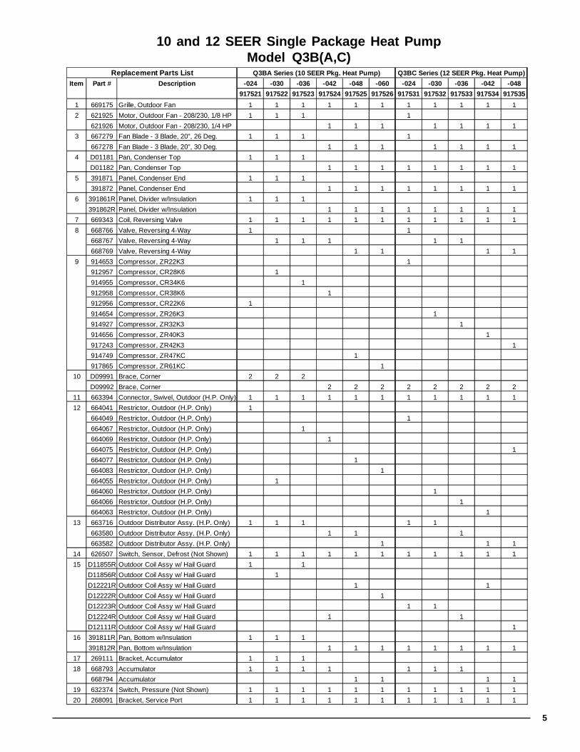
5
10 and 12 SEER Single Package Heat PumpModel Q3B(A,C)
Item Part # Description -024 -030 -036 -042 -048 -060 -024 -030 -036 -042 -048
917521 917522 917523 917524 917525 917526 917531 917532 917533 917534 917535
1 669175 Grille, Outdoor Fan 1 1 1 1 1 1 1 1 1 1 1
2 621925 Motor, Outdoor Fan - 208/230, 1/8 HP 1 1 1 1
621926 Motor, Outdoor Fan - 208/230, 1/4 HP 1 1 1 1 1 1 1
3 667279 Fan Blade - 3 Blade, 20", 26 Deg. 1 1 1 1
667278 Fan Blade - 3 Blade, 20", 30 Deg. 1 1 1 1 1 1 1
4 D01181 Pan, Condenser Top 1 1 1
D01182 Pan, Condenser Top 1 1 1 1 1 1 1 1
5 391871 Panel, Condenser End 1 1 1
391872 Panel, Condenser End 1 1 1 1 1 1 1 1
6 391861R Panel, Divider w/Insulation 1 1 1
391862R Panel, Divider w/Insulation 1 1 1 1 1 1 1 1
7 669343 Coil, Reversing Valve 1 1 1 1 1 1 1 1 1 1 1
8 668766 Valve, Reversing 4-Way 1 1
668767 Valve, Reversing 4-Way 1 1 1 1 1
668769 Valve, Reversing 4-Way 1 1 1 1
9 914653 Compressor, ZR22K3 1
912957 Compressor, CR28K6 1
914955 Compressor, CR34K6 1
912958 Compressor, CR38K6 1
912956 Compressor, CR22K6 1
914654 Compressor, ZR26K3 1
914927 Compressor, ZR32K3 1
914656 Compressor, ZR40K3 1
917243 Compressor, ZR42K3 1
914749 Compressor, ZR47KC 1
917865 Compressor, ZR61KC 1
10 D09991 Brace, Corner 2 2 2
D09992 Brace, Corner 2 2 2 2 2 2 2 2
11 663394 Connector, Swivel, Outdoor (H.P. Only) 1 1 1 1 1 1 1 1 1 1 1
12 664041 Restrictor, Outdoor (H.P. Only) 1
664049 Restrictor, Outdoor (H.P. Only) 1
664067 Restrictor, Outdoor (H.P. Only) 1
664069 Restrictor, Outdoor (H.P. Only) 1
664075 Restrictor, Outdoor (H.P. Only) 1
664077 Restrictor, Outdoor (H.P. Only) 1
664083 Restrictor, Outdoor (H.P. Only) 1
664055 Restrictor, Outdoor (H.P. Only) 1
664060 Restrictor, Outdoor (H.P. Only) 1
664066 Restrictor, Outdoor (H.P. Only) 1
664063 Restrictor, Outdoor (H.P. Only) 1
13 663716 Outdoor Distributor Assy. (H.P. Only) 1 1 1 1 1
663580 Outdoor Distributor Assy. (H.P. Only) 1 1 1
663582 Outdoor Distributor Assy. (H.P. Only) 1 1 1
14 626507 Switch, Sensor, Defrost (Not Shown) 1 1 1 1 1 1 1 1 1 1 1
15 D11855R Outdoor Coil Assy w/ Hail Guard 1 1
D11856R Outdoor Coil Assy w/ Hail Guard 1
D12221R Outdoor Coil Assy w/ Hail Guard 1 1
D12222R Outdoor Coil Assy w/ Hail Guard 1
D12223R Outdoor Coil Assy w/ Hail Guard 1 1
D12224R Outdoor Coil Assy w/ Hail Guard 1 1
D12111R Outdoor Coil Assy w/ Hail Guard 1
16 391811R Pan, Bottom w/Insulation 1 1 1
391812R Pan, Bottom w/Insulation 1 1 1 1 1 1 1 1
17 269111 Bracket, Accumulator 1 1 1
18 668793 Accumulator 1 1 1 1 1 1 1
668794 Accumulator 1 1 1 1
19 632374 Switch, Pressure (Not Shown) 1 1 1 1 1 1 1 1 1 1 1
20 268091 Bracket, Service Port 1 1 1 1 1 1 1 1 1 1 1
Replacement Parts List Q3BA Series (10 SEER Pkg. Heat Pump) Q3BC Series (12 SEER Pkg. Heat Pump)

6
10 and 12 SEER Single Package Heat PumpModel Q3B(A,C)
Item Part # Description -024 -030 -036 -042 -048 -060 -024 -030 -036 -042 -048
917521 917522 917523 917524 917525 917526 917531 917532 917533 917534 917535
21 391931 Panel, Electrical 1 1 1 1 1 1 1 1 1 1 1
22 391941 Cover, Control Panel 1 1 1
391942 Cover, Control Panel 1 1 1 1 1 1 1 1
23 663871 Pipe, Condensate Drain, Evap. 1 1 1 1 1 1 1 1 1 1 1
24 663860 Pipe, Condensate Drain, Cond. 1 1 1 1 1 1 1 1 1 1 1
25 669354 Pan, Condensate Drain 1 1 1
669353 Pan, Condensate Drain 1 1 1 1 1 1 1 1
26 250102 Collar, Duct 14" 1 1 1 1 1 1 1 1 1 1 1
27 D11891R Panel, Evaporator End w/Insulation 1 1 1
D11892R Panel, Evaporator End w/Insulation 1 1 1 1 1 1 1 1
28 250101 Collar, Duct 12" 2 2 2 2 2 2 2 2 2 2 2
29 391821R Pan, Evaporator Top w/Insulation 1 1 1
391822R Pan, Evaporator Top w/Insulation 1 1 1 1 1 1 1 1
30 663394 Connector, Swivel, Indoor 1 1 1 1 1 1 1 1 1 1 1
31 664083 Restrictor, Indoor 1
664093 Restrictor, Indoor 1
664073 Restrictor, Indoor 1 1
664080 Restrictor, Indoor 1
664060 Restrictor, Indoor 1 1
664065 Restrictor, Indoor 1
664068 Restrictor, Indoor 1
664082 Restrictor, Indoor 1
664061 Restrictor, Indoor 1
664066 Restrictor, Indoor 1
32 663580 Indoor Distributor Assy. 1 1 1 1 1 1
663719 Indoor Distributor Assy. 1
663584 Indoor Distributor Assy. 1 1 1 1
Replacement Parts List Q3BA Series (10 SEER Pkg. Heat Pump) Q3BC Series (12 SEER Pkg. Heat Pump)
33 271721R Indoor Coil Assy w/Distributor Assy. 1
D12061R Indoor Coil Assy w/Distributor Assy. 1 1
D12063R Indoor Coil Assy w/Distributor Assy. 1
D12075R Indoor Coil Assy w/Distributor Assy. 1 1
D12077R Indoor Coil Assy w/Distributor Assy. 1
D12074R Indoor Coil Assy w/Distributor Assy. 1 1
D12073R Indoor Coil Assy w/Distributor Assy. 1
D12076R Indoor Coil Assy w/Distributor Assy. 1
34 392221 Box, Control H.P. 1
392222 Box, Control H.P. 1 1 1 1 1 1 1
392223 Box, Control H.P. 1 1
392224 Box, Control H.P. 1
35 621899 Relay, SPST, NC 1 1 1 1 1 1 1 1 1 1 1
36 621867 Relay, DPST 1 1 1 1 1 1 1 1 1 1 1
37 620777 Capacitor 1
620762 Capacitor 1
620763 Capacitor 1 1
620779 Capacitor 1
620968 Capacitor 1
620888 Capacitor 1
621153 Capacitor 1
621697 Capacitor 1
621698 Capacitor 1
621944 Capacitor 1
38 269101 Bracket, Relay 1 1 1 1 1 1 1 1 1 1 1
39 621898 Relay, SPST, NO 2 2 2 2 2 2 2 2 2 2 2
40 268001 Divider, Low Voltage 1 1 1 1 1 1 1 1 1 1 1
41 626506 Switch, Limit, 35 CI/50CO 1 1 1 1 1 1 1 1 1 1 1
42 621661 Contactor 1 1 1 1 1 1 1 1
621662 Contactor 1 1 1

7
Q3B* Model Series Shown
1
2
111213
16
10
34
3
4
5
6 8
915
17
18
20
21
22
2325
27
29
303132
33
35
36
37
38
39
40
41
42
10
24
7
14
19
26
28
28

O'Fallon, MO
708016B (Replaces 708016A)
Specifications and illustrations subject to change without notice andwithout incurring obligations.
Printed in U.S.A. (10/01)
���������708016B


