16
1 Air Cooled Template Air Cooled Chiller Product Data Catalog For Modules: ASP010X, ASP015X, ASP020X, ASP030X, ASP060X Also Includes: Pump Modules, Free Cool Modules and Accessory Modules
| Date post: | 01-Jun-2018 |
| Category: |
Documents |
| Upload: | ridwan-pramudya |
| View: | 226 times |
| Download: | 0 times |

8/9/2019 Air Cooled CatalogLR
http://slidepdf.com/reader/full/air-cooled-cataloglr 1/16
Air Cooled Template
Air Cooled Chill
Product Data Catalo
For Modules: ASP010X, ASP015X, ASP020X, ASP030X, ASP060X
Also Includes: Pump Modules, Free Cool Modules and Accessory Modules
8/9/2019 Air Cooled CatalogLR
http://slidepdf.com/reader/full/air-cooled-cataloglr 2/16
Table of Contents
Model Number Nomenclature ...........................3-4
General Data Table ...........................................5-6
Pump Selection Charts .........................................7
Adjustment Charts ............................................8-9
Module Configuration ........................................ 10
Chiller Drawings ........................................... 11-12
Required Piping and Electrical Data .................... 13
Mechanical Specifications ............................. 14-15
8/9/2019 Air Cooled CatalogLR
http://slidepdf.com/reader/full/air-cooled-cataloglr 3/16
Air Cooled Modular Catalog
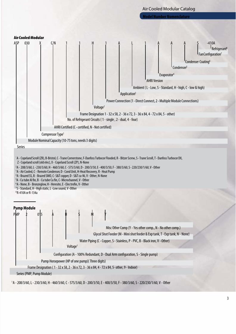
Air Cooled ModularASP 030 X C/N 1 1 H 1 A L 1 A A A S -410A
No. of Refrigerant Circuits ( 1 - single , 2 - dual, 4 - four)
AHRI Certified (C - certified, N - Not certified)
Series
Module Nominal Capacity (10-75 tons, needs 3 digits)
Compressor Type1
Frame Designation 1 - 32 x 58, 2 - 36 x 72, 3 - 36 x 84, 4 - 72 x 84, 5 - other)
Voltage2
Power Connection (1 - Direct Connect, 2 - Multiple Module Connections)
Application3
Ambient ( L - Low, S - Standard, H - high, C - low & high)
AHRI Version
Evaporator4
Condenser5
Condenser Coating6
Fan Configuration
Refrige
1 A - Copeland Scroll (ZR), B-Bristol, C - Trane Cornerstone, F-Danfoss Turbocor Flooded, R - Bitzer Screw, S - Trane Scroll, T - Danfoss Turbocor DX,Z - Copeland scroll (old elec), X - Copeland Scroll (ZP), N-None
2 A - 208/3/60, L - 230/3/60, H - 460/3/60, C - 575/3/60, D - 200/3/50, E - 400/3/50, F - 380/3/60, S - 220/230/1/60, V - Other3 A - Air Cooled, C - Remote Condenser, D - Cond Unit, H-Heat Recovery, R - Heat Pump
4 A - Brazed SS, B - Brazed SMO, C- S&T copper, D - S&T cu-Ni, V - Other, N-None5A - Cu tube Al fin, B - Cu tube Cu fin, C- Microchannel, V - Other6 A - None, B - Bronzeglow, H - Heresite, E - Electrofin, V - Other7 S - Standard, H - High static, L -Low sound, V -Other8 R-410A or R-134a
Pump Module
PMP 2 015 A H S M Y
Voltage1
Configuration (A - 100% Redundant, D - Dual Arm configuration, S - Single pump)
Series (PMP, Pump Module)
Frame Designation ( 1 - 32 x 58, 2 - 36 x 72, 3 - 36 x 84, 4 - 72 x 84, 5- other, 9 - Indoor)
Pump Horsepower (HP of one pump)( Three digits)
Water Piping (C - Copper, S - Stainless, P - PVC, B - Black iron, V - Other)
Glycol Shot Feeder (M - Mini shot feeder & Exp tank, T - Exp tank, N - None)
Misc Other Comp (Y - Yes other comp., N - No other comp.)
1 A - 208/3/60, L - 230/3/60, H - 460/3/60, C - 575/3/60, D - 200/3/50, E - 400/3/50, F - 380/3/60, S - 220/230/1/60, V - Other
Model Number Nomenclature
8/9/2019 Air Cooled CatalogLR
http://slidepdf.com/reader/full/air-cooled-cataloglr 4/16
Air Cooled Modular Catalog
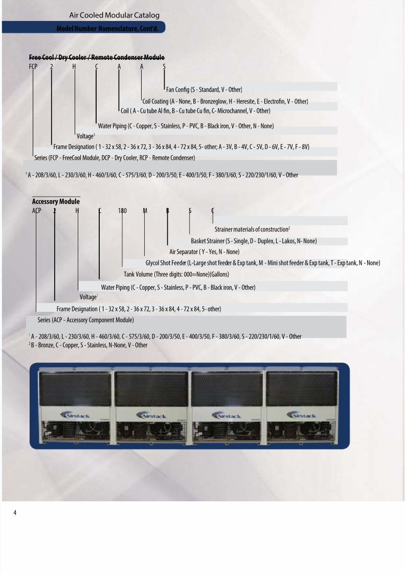
Free Cool / Dry Cooler / Remote Condenser ModuleFCP 2 H C A A S
Coil ( A - Cu tube Al fin, B - Cu tube Cu fin, C- Microchannel, V - Other)
Water Piping (C - Copper, S - Stainless, P - PVC, B - Black iron, V - Other, N - None)
Series (FCP - FreeCool Module, DCP - Dry Cooler, RCP - Remote Condenser)
Frame Designation ( 1 - 32 x 58, 2 - 36 x 72, 3 - 36 x 84, 4 - 72 x 84, 5- other; A - 3V, B - 4V, C - 5V, D - 6V, E - 7V, F - 8V)
Voltage1
Coil Coating (A - None, B - Bronzeglow, H - Heresite, E - Electrofin, V - Other)
Fan Config (S - Standard, V - Other)
1 A - 208/3/60, L - 230/3/60, H - 460/3/60, C - 575/3/60, D - 200/3/50, E - 400/3/50, F - 380/3/60, S - 220/230/1/60, V - Other
Accessory ModuleACP 2 H C 180 M B S C
Tank Volume (Three digits: 000=None)(Gallons)
Water Piping (C - Copper, S - Stainless, P - PVC, B - Black iron, V - Other)
Series (ACP - Accessory Component Module)
Frame Designation ( 1 - 32 x 58, 2 - 36 x 72, 3 - 36 x 84, 4 - 72 x 84, 5- other)
Voltage1
Glycol Shot Feeder (L-Large shot feeder & Exp tank, M - Mini shot feeder & Exp tank, T - Exp tank, N - None
Air Separator ( Y - Yes, N - None)
Basket Strainer (S - Single, D - Duplex, L - Lakos, N- None)
Strainer materials of construction2
1 A - 208/3/60, L - 230/3/60, H - 460/3/60, C - 575/3/60, D - 200/3/50, E - 400/3/50, F - 380/3/60, S - 220/230/1/60, V - Other2 B - Bronze, C - Copper, S - Stainless, N-None, V - Other
Model Number Nomenclature, Cont’d.
8/9/2019 Air Cooled CatalogLR
http://slidepdf.com/reader/full/air-cooled-cataloglr 5/16
Air Cooled Modular Catalog
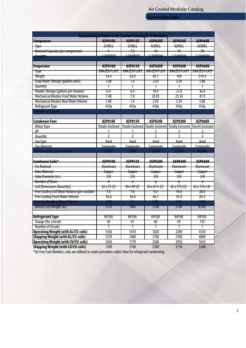
General Data Table of Air Cooled Standard –X ModulesCompressor ASP010X ASP015X ASP020X ASP030X ASP060X
Type SCROLL SCROLL SCROLL SCROLL SCROLLNominal Capacity (per compressor) 5 7.5 10 15 30Quantity 2-TANDEM 2-TANDEM 2-TANDEM 2-TANDEM 2-TANDEM
Evaporator ASP010X ASP015X ASP020X ASP030X ASP060XType BRAZED PLATE BRAZED PLATE BRAZED PLATE BRAZED PLATE BRAZED PLATEWeight 54.4 63.8 83.7 100 214.4Evap Water Storage (gallons each) 1.08 1.4 2.03 2.54 5.86Quantity 1 1 1 1 1Header Storage (gallons per module) 6.4 6.4 18.0 21.0 36.4Mechanical Module Front Water Volume 7.48 7.8 20.03 23.54 41.9Mechanical Module Rear Water Volume 1.08 1.4 2.03 2.54 5.86Refrigerant Type 410a 410a 410a 410a 410aNumber of Circuits 1 1 1 1 1
Condenser Fans ASP010X ASP015X ASP020X ASP030X ASP060XMotor Type Totally Enclosed Totally Enclosed Totally Enclosed Totally Enclosed Totally EnclosedHP 1 1 2 2 2Quantity 2 2 2 2 4Fan Type Axial Axial Axial Axial AxialFan Material Composite Composite Composite Composite CompositeAir Flow (cfm) (per module) 6,600 8,500 16,000 22,000 44,000
Condenser Coils* ASP010X ASP015X ASP020X ASP030X ASP060XFin Material Aluminum Aluminum Aluminum Aluminum AluminumTube Material Copper Copper Copper Copper CopperTube Diameter (in.) 3/8 3/8 3/8 3/8 3/8
Number of Rows 4 6 6 6 6Coil Dimensions (Quantity) 32 x 51 (2) 30 x 49 (2) 30 x 61½ (2) 42 x 73½ (2) 42 x 73½ (4)Free Cooling Coil Water Volume (per module) 7.0 7.0 9.2 14.4 28.8Free Cooling Front Water Volume 16.6 16.6 40.7 45.9 83.4Free Cooling Rear Water Volume 1.08 1.4 2.03 2.54 5.86Module Dry Weight (lb.) 1370 1400 1700 2100 4,000
Refrigerant Type R410A R410A R410A R410A R410ACharge (lbs./circuit) 36 41 60 65 135Number of Circuits 1 1 1 1 1
Operating Weight (with AL/CU coils) 1430 1470 1820 2290 4350Shipping Weight (with AL/CU coils) 1370 1400 1700 2100 4000
Operating Weight (with CU/CU coils) 1650 1770 2300 2920 5610Shipping Weight (with CU/CU coils) 1590 1700 2180 2730 5260*On Free Cool Modules, coils are utilized as water precoolers rather than for refrigerant condensing.
General Data Table
8/9/2019 Air Cooled CatalogLR
http://slidepdf.com/reader/full/air-cooled-cataloglr 6/16
Air Cooled Modular Catalog
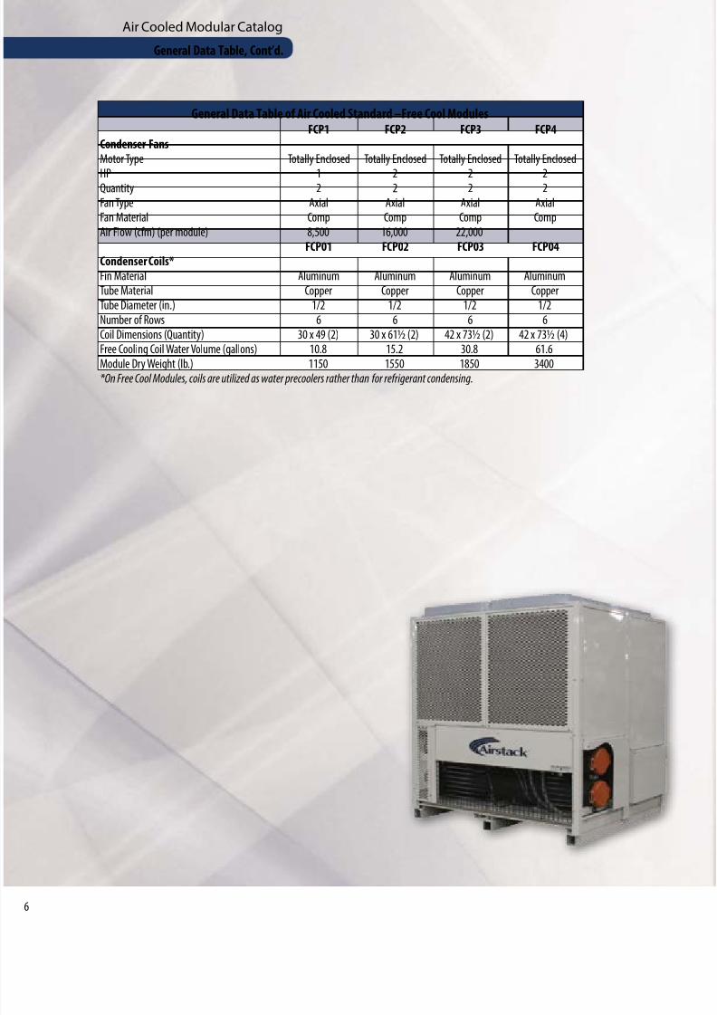
General Data Table of Air Cooled Standard –Free Cool ModulesFCP1 FCP2 FCP3 FCP4
Condenser FansMotor Type Totally Enclosed Totally Enclosed Totally Enclosed Totally Enclosed
HP 1 2 2 2Quantity 2 2 2 2Fan Type Axial Axial Axial AxialFan Material Comp Comp Comp CompAir Flow (cfm) (per module) 8,500 16,000 22,000
FCP01 FCP02 FCP03 FCP04Condenser Coils*Fin Material Aluminum Aluminum Aluminum AluminumTube Material Copper Copper Copper CopperTube Diameter (in.) 1/2 1/2 1/2 1/2Number of Rows 6 6 6 6Coil Dimensions (Quantity) 30 x 49 (2) 30 x 61½ (2) 42 x 73½ (2) 42 x 73½ (4)
Free Cooling Coil Water Volume (gallons) 10.8 15.2 30.8 61.6Module Dry Weight (lb.) 1150 1550 1850 3400*On Free Cool Modules, coils are utilized as water precoolers rather than for refrigerant condensing.
General Data Table, Cont’d.
8/9/2019 Air Cooled CatalogLR
http://slidepdf.com/reader/full/air-cooled-cataloglr 7/16
Air Cooled Modular Catalog
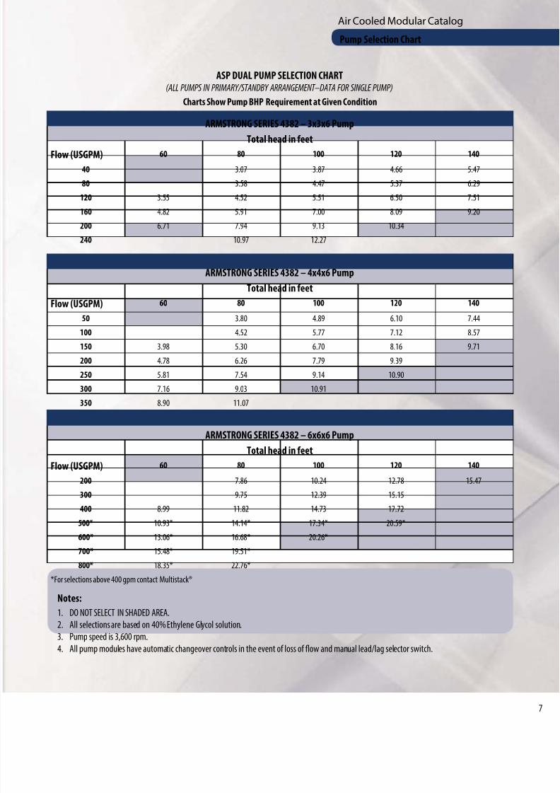
ASP DUAL PUMP SELECTION CHART(ALL PUMPS IN PRIMARY/STANDBY ARRANGEMENT–DATA FOR SINGLE PUMP)
Charts Show Pump BHP Requirement at Given Condition
ARMSTRONG SERIES 4382 – 3x3x6 Pump
Total head in feetFlow (USGPM) 60 80 100 120 140
40 3.07 3.87 4.66 5.47
80 3.58 4.47 5.37 6.29
120 3.55 4.52 5.51 6.50 7.51
160 4.82 5.91 7.00 8.09 9.20
200 6.71 7.94 9.13 10.34
240 10.97 12.27
ARMSTRONG SERIES 4382 – 4x4x6 PumpTotal head in feet
Flow (USGPM) 60 80 100 120 140
50 3.80 4.89 6.10 7.44
100 4.52 5.77 7.12 8.57
150 3.98 5.30 6.70 8.16 9.71
200 4.78 6.26 7.79 9.39
250 5.81 7.54 9.14 10.90
300 7.16 9.03 10.91
350 8.90 11.07
ARMSTRONG SERIES 4382 – 6x6x6 Pump
Total head in feet
Flow (USGPM) 60 80 100 120 140
200 7.86 10.24 12.78 15.47
300 9.75 12.39 15.15
400 8.99 11.82 14.73 17.72
500* 10.93* 14.14* 17.34* 20.59*
600* 13.06* 16.68* 20.26*
700* 15.48* 19.51*800* 18.35* 22.76*
*For selections above 400 gpm contact Multistack®
Notes:
1. DO NOT SELECT IN SHADED AREA.
2. All selections are based on 40% Ethylene Glycol solution.
3. Pump speed is 3,600 rpm.
4. All pump modules have automatic changeover controls in the event of loss of flow and manual lead/lag selector switch.
Pump Selection Chart
8/9/2019 Air Cooled CatalogLR
http://slidepdf.com/reader/full/air-cooled-cataloglr 8/16
Air Cooled Modular Catalog
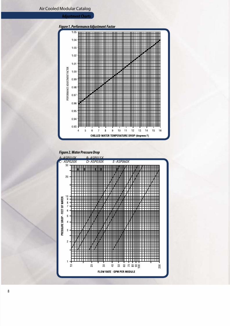
P E R F O R M A N C E A D J U S T M E N T F A C T O R
Figure 1. Performance Adjustment Factor
Figure 2. Water Pressure Drop
A- ASP010X B- ASP015X
C- ASP020X D- ASP030X E- ASP060X
A B C D E
Adjustment Charts
8/9/2019 Air Cooled CatalogLR
http://slidepdf.com/reader/full/air-cooled-cataloglr 9/16
Air Cooled Modular Catalog
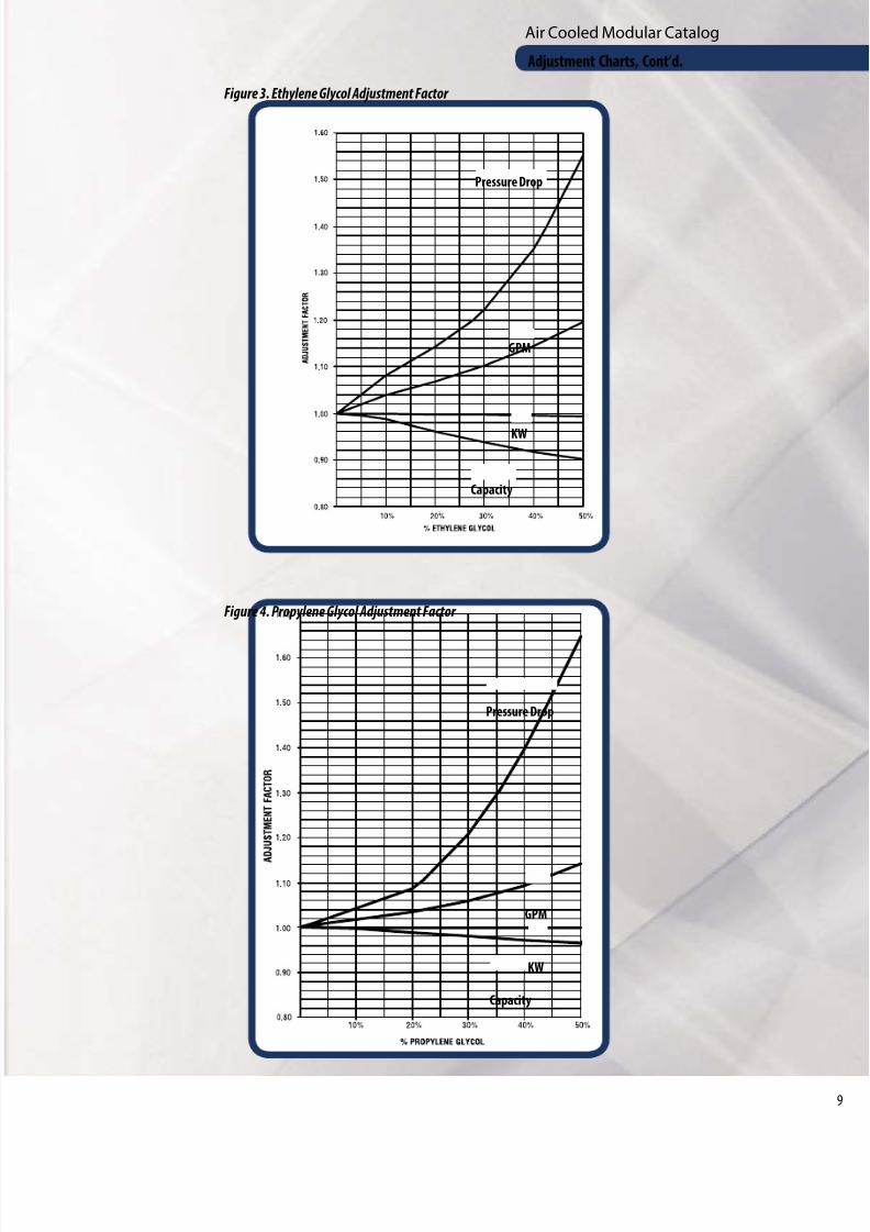
Figure 3. Ethylene Glycol Adjustment Factor
Figure 4. Propylene Glycol Adjustment Factor
Pressure Drop
Pressure Drop
GPM
GPM
KW
KW
Capacity
Capacity
Adjustment Charts, Cont’d.

8/9/2019 Air Cooled CatalogLR
http://slidepdf.com/reader/full/air-cooled-cataloglr 10/160
Air Cooled Modular Catalog
IMPORTANT MODULE CONFIGURATION INFORMATION
PMP1, PMP2, PMP3, PMP4, PMP9 PUMP MODULE:1. When present, a Pump Module is only allowed in the “Front”
position.
2. Incoming water to the chiller system must enter at the PumpModule.
3. Leaving water from the chiller system may be from either endof the chiller.
FCP1, FCP2, FCP3 FREE COOL MODULE:1. When present, incoming system water must enter through the
Free Cool Modules prior to entering an ASP010X, 15X, 20X, 30X,60X Chiller Module.
2. You may not attach a Rear Free Cool Module to a Front ASP010X,15X, 20X, 30X, 60X Chiller Module.
ACP GLYCOL FEEDER MODULE:1. An ACP Glycol Feeder Module may be attached in any rearposition.
ASP010X, 15X, 20X, 30X, 60X CHILLER MODULE:1. The maximum number of ASP010X, 015X, 020X, or
030X,modules with a single Master Module is 14 (i.e., (1)Front-Master, (6) Front-Slaves, and (7) Rear-Slaves). For 60Xmodules, the maximum is nine modules.
2. You may have more than one Master Module in a singlechiller bank.
3. Piping sides of an ASP010X, 015X, 020X, 030X, 060X chillerwithout Free Cool or Pump Modules attached are field
selectable.
VALID CONFIGURATIONS
INVALID CONFIGURATIONS
TYPICAL ASP060X CONFIGURATION
LEGEND: FIRST LETTERM=Master Chiller Module (ASP010X, 15X, 20X, 30X or 60X)
S = Slave Chiller Module (ASP010X, 15X, 20X, 30X or 60X)
P= Pump Module (ASP-00P)
F = Free Cool Module (ASP-1FX, 2FX, 3FX)
G = Glycol Feeder Module (ASP-00G)
SECOND LETTERF = Front Module
R = Rear Module
Problem: Cannot have a stand alone rear module.
Solution: Make Slave Rear a Slave Front.
Problem: Pump module after Master.
Solution: Swap placement so incoming water enters at the pump module.
Problem: Glycol Feeder Module is attached in a front position.
Solution: Move Glycol Feeder Module to rear position and exchange Slave Rear Module fo
Slave Front Module.
FRONT OF CHILLER BANK IS TOWARDTHE BOTTOM OF THE PAGE(Master Module location determines front of chiller)
For other configurations, contact your local Multistack® Representative.
PF
SR
PF
PF
MF
SR
MF
MF
SR
PF
PF
PF
FR
SR
SR
FR
PF
Tank FF
SR SR
SR
SF
FF
SF
SR
SF
PF
SR
SR
MF
MF
FF
FR
SR
SR
SR
SF
SF
MF
SR
SF
SR
SR SR
MF
MF
SR SR
SR
SF
MF
SF
SR
SF
SF
SR
SR
GF
SF
MF SF
SR
SR
SR
SR SR
SF
SF
SF
SR
SF
SF
SR
SF
M S S S
Module Configuration
8/9/2019 Air Cooled CatalogLR
http://slidepdf.com/reader/full/air-cooled-cataloglr 11/16
Air Cooled Modular Catalog
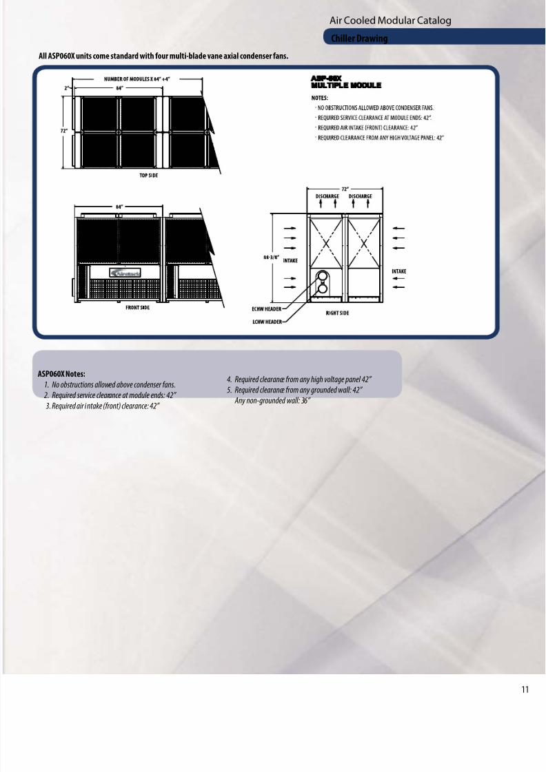
ASP060X Notes:
1. No obstructions allowed above condenser fans.
2. Required service clearance at module ends: 42”
3. Required air i ntake (front) clearance: 42”
4. Required clearance from any high voltage panel 42”
5. Required clearance from any grounded wall: 42”
Any non-grounded wall: 36”
All ASP060X units come standard with four multi-blade vane axial condenser fans.
INTAKE
Chiller Drawing
8/9/2019 Air Cooled CatalogLR
http://slidepdf.com/reader/full/air-cooled-cataloglr 12/162
Air Cooled Modular Catalog
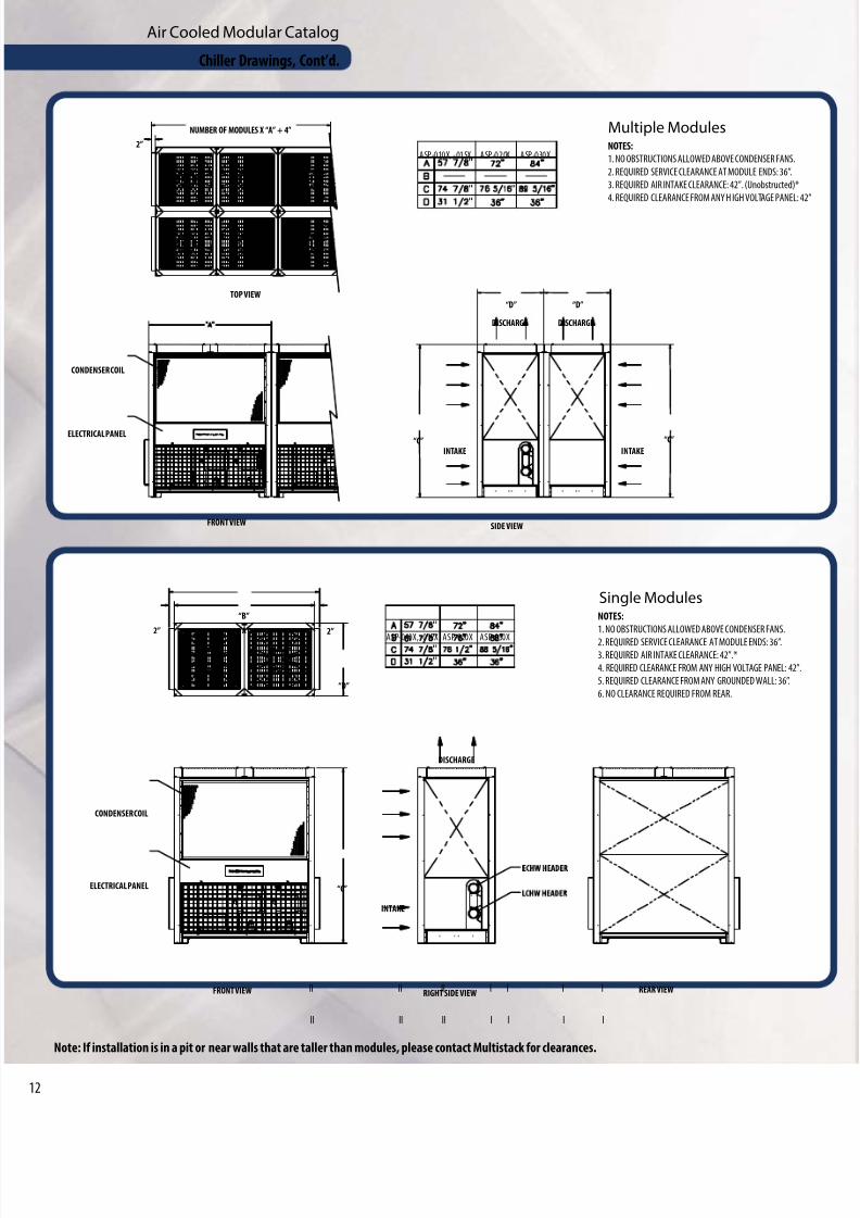
NOTES:
1. NO OBSTRUCTIONS ALLOWED ABOVE CONDENSER FANS.
2. REQUIRED SERVICE CLEARANCE AT MODULE ENDS: 36”.
3. REQUIRED AIR INTAKE CLEARANCE: 42”. (Unobstructed)*
4. REQUIRED CLEARANCE FROM ANY H IGH VOLTAGE PANEL: 4
NUMBER OF MODULES X “A” + 4”
2”
TOP VIEW
CONDENSER COIL
ELECTRICAL PANEL
INTAKE INTAKE
“C” “C”
DISCHARGE DISCHARGE
“D” “D”
FRONT VIEWSIDE VIEW
ll ll ll l l l l
ASP-010X, -015X ASP-020X ASP-030X
Multiple Modules
NOTES:
1. NO OBSTRUCTIONS ALLOWED ABOVE CONDENSER FANS.
2. REQUIRED SERVICE CLEARANCE AT MODULE ENDS: 36”.3. REQUIRED AIR INTAKE CLEARANCE: 42”.*
4. REQUIRED CLEARANCE FROM ANY HIGH VOLTAGE PANEL: 42”.
5. REQUIRED CLEARANCE FROM ANY GROUNDED WALL: 36”.
6. NO CLEARANCE REQUIRED FROM REAR.
“B”
“A”
“D”
2”2”
“C”
CONDENSER COIL
ELECTRICAL PANEL
FRONT VIEW RIGHT SIDE VIEW
INTAKE
DISCHARGE
REAR VIEW
ll ll ll l l l l
ASP-010X, -015X ASP-020X ASP-030X
Single Modules
Chiller Drawings, Cont’d.
Note: If installation is in a pit or near walls that are taller than modules, please contact Multistack for clearances.
8/9/2019 Air Cooled CatalogLR
http://slidepdf.com/reader/full/air-cooled-cataloglr 13/16
Air Cooled Modular Catalog
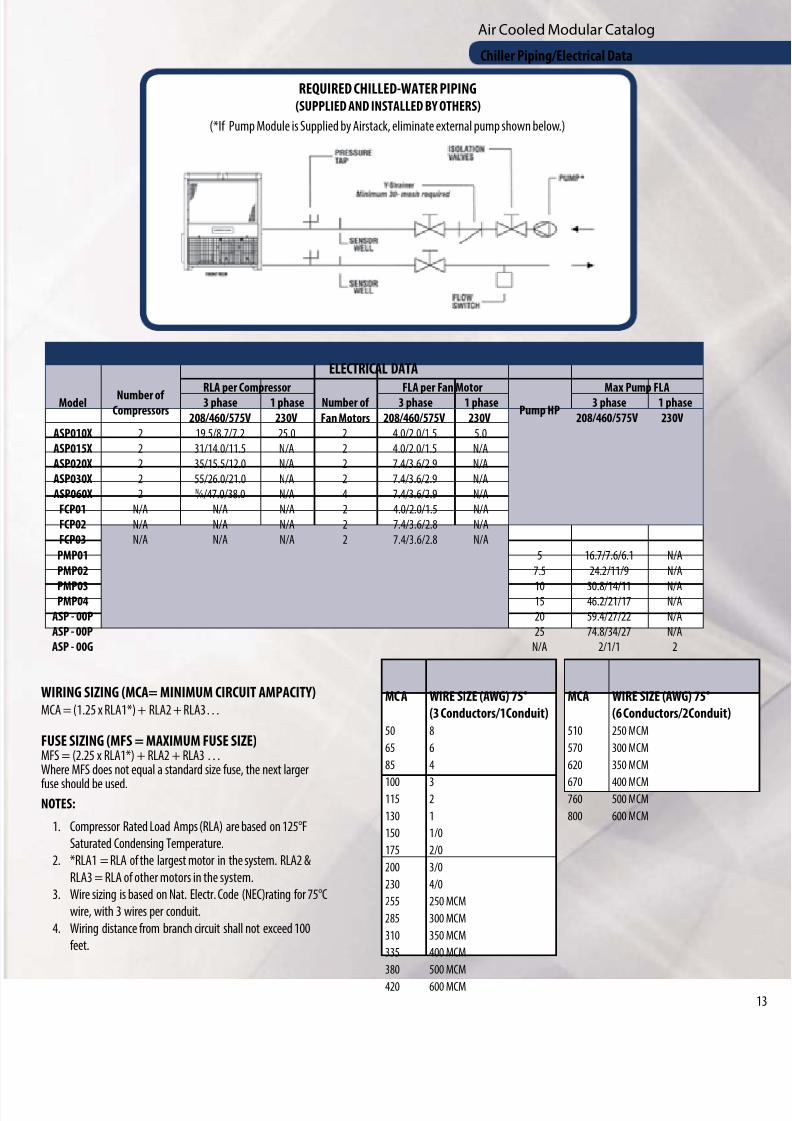
REQUIRED CHILLED-WATER PIPING(SUPPLIED AND INSTALLED BY OTHERS)
(*If Pump Module is Supplied by Airstack, eliminate external pump shown below.)
ELECTRICAL DATA
Model Number ofCompressors
RLA per Compressor FLA per Fan Motor Max Pump FLA3 phase 1 phase Number of
Fan Motors
3 phase 1 phasePump HP
3 phase 1 phase
208/460/575V 230V 208/460/575V 230V 208/460/575V 230V
ASP010X 2 19.5/8.7/7.2 25.0 2 4.0/2.0/1.5 5.0
ASP015X 2 31/14.0/11.5 N/A 2 4.0/2.0/1.5 N/A
ASP020X 2 35/15.5/12.0 N/A 2 7.4/3.6/2.9 N/A
ASP030X 2 55/26.0/21.0 N/A 2 7.4/3.6/2.9 N/A
ASP060X 2 N ⁄ A/47.0/38.0 N/A 4 7.4/3.6/2.9 N/A
FCP01 N/A N/A N/A 2 4.0/2.0/1.5 N/A
FCP02 N/A N/A N/A 2 7.4/3.6/2.8 N/A
FCP03 N/A N/A N/A 2 7.4/3.6/2.8 N/A
PMP01 5 16.7/7.6/6.1 N/A
PMP02 7.5 24.2/11/9 N/A
PMP03 10 30.8/14/11 N/APMP04 15 46.2/21/17 N/A
ASP - 00P 20 59.4/27/22 N/A
ASP - 00P 25 74.8/34/27 N/A
ASP - 00G N/A 2/1/1 2
WIRING SIZING (MCA= MINIMUM CIRCUIT AMPACITY)MCA = (1.25 x RLA1*) + RLA2 + RLA3…
FUSE SIZING (MFS = MAXIMUM FUSE SIZE)MFS = (2.25 x RLA1*) + RLA2 + RLA3 …Where MFS does not equal a standard size fuse, the next larger
fuse should be used.NOTES:
1. Compressor Rated Load Amps (RLA) are based on 125°F
Saturated Condensing Temperature.
2. *RLA1 = RLA of the largest motor in the system. RLA2 &
RLA3 = RLA of other motors in the system.
3. Wire sizing is based on Nat. Electr. Code (NEC)rating for 75°C
wire, with 3 wires per conduit.
4. Wiring distance from branch circuit shall not exceed 100
feet.
MC A WIRE SIZE (AWG) 75°
(3 Conductors/1Conduit)
50 8
65 6
85 4
100 3115 2
130 1
150 1/0
175 2/0
200 3/0
230 4/0
255 250 MCM
285 300 MCM
310 350 MCM
335 400 MCM
380 500 MCM
420 600 MCM
MCA WIRE SIZE (AWG) 75°
(6 Conductors/2Conduit)
510 250 MCM
570 300 MCM
620 350 MCM
670 400 MCM760 500 MCM
800 600 MCM
Chiller Piping/Electrical Data
8/9/2019 Air Cooled CatalogLR
http://slidepdf.com/reader/full/air-cooled-cataloglr 14/164
Air Cooled Modular Catalog
GENERALChiller Modules shall be ETL listed in accordance with UL Standard 1995, CSA certified per Standard C22.2#236, and bear the ASME UM stamp on all water-to-refrigerant heat exchangers.
Modules shall ship wired and charged with refrigerant. All modules shall be factory run-tested prior to shipment. Compressors, heat exchangers, condenserfans, piping, and controls shall be mounted on a heavy-gauge steel frame. Electrical controls, contactors, and relays for each module shall be mounted withinthat module. The module shall be provided within a steel enclosure suitable for outdoor use. Exposed steel surfaces shall be provided with a powder-coatpaint finish.
CHILLED-WATER MAINSEach module shall include supply and return mains for chilled water. Grooved end connections are provided for interconnection to four-inch (ASP 10X, 15X),six-inch (ASP 20X and 30X) or eight-inch (60X) standard piping with Victaulic-type couplings. Each inlet water header shall incorporate a built-in, 30-meshin-line strainer system to prevent heat exchanger fouling.
EVAPORATORSEach evaporator shall be a brazed-plate heat exchanger constructed of 316 stainless steel, and be designed, tested, and stamped in accordance with U.L. 1995650 PSIG working pressure.
COMPRESSOREach module shall contain hermetic scroll compressor(s) mounted to the module with rubber-in-shear isolators. Each system shall also include high discharge-pressure and low suction-pressure safety cut-outs.
CONDENSER COILSAir cooled condenser coils shall have aluminum fins mechanically bonded to copper tubing. Condensers shall have integral subcooling circuitry and be factoryleak-tested.
CONDENSER FANSEach module shall contain dual condenser fans for each refrigerant circuit. These fans shall be multi-blade vane-axial type, made of plastic composite material forquiet operation. Fans shall be direct driven at a maximum rpm of 1,150. All fan motors shall be pressure controlled and suitable for outdoor use. ASP 60X moduleshave four fans.
CENTRAL CONTROL SYSTEMScheduling of the various compressors shall be performed by a microprocessor-based control system (Master Controller). A new lead compressor is selected
every 24 hours to ensure even distribution of compressor run time. The Master Controller shall monitor and report the following on each refrigeration system:• Discharge Pressure Fault
- Suction Pressure Fault
- Compressor Winding Temperature Fault
- Suction Temperature
- Evaporator Leaving Chilled-Water Temperature
The Master Controller shall monitor and report the following system parameters:
• Chilled-Water Entering and Leaving Temperature
- Discharge Refrigerant Temperature
- Chilled-Water Flow Fault
An out-of-tolerance indication from these controls or sensors shall cause a “fault” indication at the Master Controller and shutdown of that compressor, withthe transfer of load requirements to the next available compressor. In the case of a System Fault, the entire chiller will be shut down. When a fault occurs, theMaster Controller shall record conditions at the time of the fault and store the data for recall. This information shall be capable of being recalled through thekeypad of the Master Controller and displayed on the Master Controller’s LCD. A history of faults shall be maintained, including date and time-of-day of eachfault (up to the last 20 occurrences).
Individual monitoring of leaving chilled-water temperatures from each refrigeration system shall be programmed to protect against freeze-up.
The control system shall monitor entering and leaving chilled water temperatures to determine system load, and select the number of compressor circuitsrequired to operate. Response times and set points shall be adjustable.
LOW AMBIENT OPERATIONEach refrigerant circuit shall include all refrigerant specialties to provide reliable operation down to 20°F ambient. With proper freeze protection.
Mechanical Specifications
8/9/2019 Air Cooled CatalogLR
http://slidepdf.com/reader/full/air-cooled-cataloglr 15/16
Air Cooled Modular Catalog
Mechanical Specifications, Cont’d.
OPTIONAL LOW AMBIENT TO -20°FThe chiller shall incorporate appropriate refrigerant specialties, including a properly sized refrigerant receiver and flooded head pressure control valves fooperation to -20°F.
OPTIONAL SINGLE-POINT POWER CONNECTIONThe chiller shall be provided with a single-point power connection. This will include pre-engineered wiring for field installation and connection to a factory
mounted chiller junction box. The junction box shall include individual fusing for each Module Set and provide a single point of connection to building power
OPTIONAL FREE COOLING MODULEFree Cooling Modules shall interconnect through the common chiller header system and require no additional water connections. Free Cooling Modules shalinclude glycol cooling coils, temperature-controlled fans, and an automatic 3-way bypass valve to eliminate the need for mechanical cooling under low-ambient conditions. The module shall be completely factory-assembled and tested before shipment.
OPTIONAL PUMP MODULEThe Pump Module shall be interconnected through the common chiller header system and require no additional water connections. The Pump Module wilbecome an integral part of the chiller system. The Pump Module shall incorporate dual in-line centrifugal pumps in a Primary/Standby pumping arrangementPump starters and controls shall be provided to enable manual selection of lead pump. In addition, in the event of a loss-of-flow failure of the chilled-watesystem, the Pump Module controls shall disable the lead pump and automatically start the standby pump. The Pump Module shall be completely factoryassembled and tested prior to shipment.
OPTIONAL TANK MODULEA factory-assembled Tank Module shall be provided, including an insulated chilled water tank. The tank shall be pressure-rated at 150 psi minimum. TankModules shall interconnect through the common chiller header system and require no additional water connections. The Tank Module will become an integrapart of the chiller system. The Tank Module shall be provided with proper drain and fill valving.
OPTIONAL GLYCOL FEEDER MODULEThe optional Glycol Feeder and Expansion Tank shall be incorporated into the chiller system through a modular arrangement and interconnect through thecommon chiller header system, requiring no additional water connections. The system shall include a 48-gallon storage/mixing tank with lid and cover, pumpsuction hose with inlet strainer, pressure pump with thermal cut-out and integral pressure switch, pre-charged accumulator tank with EPDM diaphragm,manual diverter valve for purging and agitating contents of storage tank, adjustable 5-55 psi pressure regulating valve with pressure gauge, fast fill lever,integral replaceable strainer, built-in check valve, and built-in shutoff valve. The glycol feeder system shall be compatible with glycol solutions of up to 50%concentration. The pump shall be capable of running dry without damage. The expansion tank shall be welded steel with a butylrubber diaphragm, and
capable of a maximum operating temperature of 240°F and a maximum working pressure of 100 psig. The tank shall be interconnected through the commonchiller header system and require no additional water connections. The module shall be completely factory assembled and -tested prior to shipment.
OPTIONAL SOUND-ATTENUATION MODULE
1. Each Free Cooling module shall have VFD-controlled condenser fan motors soft start and precise fan speed control.
2. Each mechanical cooling module shall have oversized condenser coils and VFD controlled condenser fan motors that modulate to maintain head pres
sure for precise fan speed control. Fans shall have acoustically optimized fan blades utilizing a composite material. Compressors shall be wrapped with
high-temperature acoustic covers consisting of a dense-design fabric exterior with quilted acoustical fiberglass interior and open edges sealed with
silicone coated fabric with hook and loop closures.
8/9/2019 Air Cooled CatalogLR
http://slidepdf.com/reader/full/air-cooled-cataloglr 16/16
1065 Maple Avenue P.O. Box 510 Sparta, WI 54656
Phone 608-366-2400 • Fax 608-366-2450
www.multistack.com
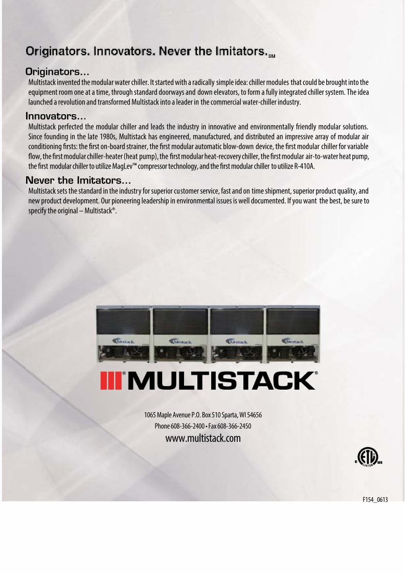
Originators…Multistack invented the modular water chiller. It started with a radically simple idea: chiller modules that could be brought into the
equipment room one at a time, through standard doorways and down elevators, to form a fully integrated chiller system. The idea
launched a revolution and transformed Multistack into a leader in the commercial water-chiller industry.
Innovators…Multistack perfected the modular chiller and leads the industry in innovative and environmentally friendly modular solutions.
Since founding in the late 1980s, Multistack has engineered, manufactured, and distributed an impressive array of modular air
conditioning firsts: the first on-board strainer, the first modular automatic blow-down device, the first modular chiller for variable
flow, the first modular chiller-heater (heat pump), the first modular heat-recovery chiller, the first modular air-to-water heat pump,
the first modular chiller to utilize MagLev™ compressor technology, and the first modular chiller to utilize R-410A.
Never the Imitators…Multistack sets the standard in the industry for superior customer service, fast and on time shipment, superior product quality, and
new product development. Our pioneering leadership in environmental issues is well documented. If you want the best, be sure tospecify the original – Multistack®.


