Founded by the inventor of modern air conditioning, Carrier is the world’s
leader in high-technology heating, air-conditioning and refrigeration solutions.
Carrier experts provide sustainable solutions, integrating energy-efficient
products, building controls and energy services for residential, commercial,
retail, transport and food service customers. Carrier is a part of UTC Build
ing & Industrial Systems, a unit of United Technologies Corp., a leading
provider to the aerospace and building systems industries worldwide.
With a broad portfolio of advanced technical patent awards, our global R&D
center in Shanghai develops innovative heat, ventilation and air-conditioning
(HVAC) solutions.
Turn To The Experts
In 1998, Time magazine named Dr. Carrier oneof its 20 most influential builders and titans ofthe 20thcentury.
9
Operating Range, 30RB039S~160S
0 5 10 15 20 25
Evaporator leaving water temperature,℃
Operating range
Out
side
air
tem
pera
ture
,o C
Full load
Minimum load
Cooling mode
Evaporator
Entering water temperature at start-up
Leaving water temperature during operation
Entering/leaving water temperature difference
Condenser
Outdoor air temperature*
7.5℃
5℃
K3
-10℃
Minimum Maximum
Minimum Maximum
30℃
20℃
K10
48℃
* Maximum outside temperature: For transport and storage of the 30RB/RQ units the minimum and maximum allowable temperatures are -20℃ and +48℃. It is recommended that these temperatures are used for transport by container.
50
45
40
35
30
25
20
15
10
5
0
-5
-10
-15
10
Operating Range, 30RQ039S~160S
Operating range - cooling mode Operating range - heating mode
Cooling mode
Water heat exchanger (Evaporator)
Entering water temperature at start-up
Leaving water temperature during operation
Entering/leaving water temperature difference
Air heat exchanger (Condenser)
Outdoor air temperature*
Minimum
7.5℃
5℃
K3
Maximum
Minimum Maximum
30℃
℃20
K10
48℃
Heating mode
Water heat exchanger (Condenser)
Entering water temperature at start-up
Leaving water temperature during operation
Entering/leaving water temperature difference
Air heat exchanger (Evaporator)
Outdoor air temperature
8℃
25℃
K3
-10℃*
Minimum Maximum
Minimum Maximum
30℃
55℃
K10
40℃
-20
-10
0
10
20
30
40
50
0 5 10 15 20 25
Full load
Minimum load
Out
side
air
tem
pera
ture
, ℃
Evaporator leaving water temperature, ℃
* Maximum outside temperature: For transport and storage of the 30RB/RQ units the minimum and maximum allowable temperatures are -20℃ and +48℃. It is recommended that these temperatures are used for transport by container.
* Min -15℃ during part load operation
20
25
30
35
40
45
50
55
60
-20 -10 0 10 20 30 40 50
Leav
ing
wat
er te
mpe
ratu
re, ℃
Outdside air temperature, ℃
Full load
Minimum load
-10℃
11
Options & accessories
Options
Blygold PoluAl
Gold Fins
Super low noise
Soft starter
Winter operation
Fixed speed dual
pump hydronic module
Unit without hydronic
module
J-Bus gateway
BacNet gateway
LonTalk gateway
No.
002B
003A
015LS
025
028
116C
116D
148B
148C
148D
Description
Coils with factory-applied
Blygold Polual treatment
Fins made of pre-treated aluminium
(polyurethane and epoxy)
Acoustic compressor enclosure and
low speed fans
Electronic compressor starter
Fan speed control
by frequency inverter
Provide fixed speed dual pumps of
200KPa external pressure
Flexible for customer to purchase
and install the water components
by themselves
Two-directional communication board
with J-Bus protocol
Two-directional communication board
with BacNet protocol
Two-directional communication board
with LonTalk protocol
Advantages
Improved corrosion resistance,
recommended for heavy marine
and industrial environments
Improved corrosion resistance,
recommended for light marine
environments
Super low operating noise
Reduced compressor
start-up current
Stable operation between
-10 ℃and -20 ℃ outdoor air
temperature
Easy and fast installation,
operating safety
-
East connection by
communication bus to a
building management system
East connection by
communication bus to a
building management system
East connection by
communication bus to a
building management system
Use
30RB039-160S
30RB039-160S
30RB039-160S
30RQ039-160S
30RB039S-080S
30RQ039S-078S
30RB039S-080S
30RB039-160S
30RQ039-160S
30RB039-160S
30RQ039-160S
30RB039-160S
30RQ039-160S
30RB039-160S
30RQ039-160S
30RB039-160S
30RQ039-160S
12
Dimensions/Clearances
30RB039S~080S/30RQ039S-078S
2
1
1
2
1061
1330
2050
519
22241
9
1000
1000 1000
1000
Control box
Water outlet
Water inlet
Required clearances for air entry
Recommended space for maintenance
Air outlet - do not obstruct
Power supply inlet
2
1
Legend:All dimensions are given in mm
13
Dimensions/Clearances
30RB100S~160S/30RQ100S-160S
2 2
1
1
1
1
2050
1000
1000
1330
222 41
9
9002258
1000
1000
Control box
Water outlet
Water inlet
Required clearances for air entry
Recommended space for maintenance
Air outlet - do not obstruct
Power supply inlet
2
1
Legend:All dimensions are given in mm
14
Multiple Chiller Installation
Multiple Chiller Installation
Note: If the height of wall exceeds 2m, please contact local Carrier Sales & Service Corporation.
WallWall
Unit's footprint
Square hole 100x100
Section F - F
Note: 4 foot screws M1x220
Square hole 100x100
250
250
250
50
300
150
P3 P4
C
A
F
P2P1
F
B D
Section F - F
Note: 4 foot screws M16x220
30RB039S
30RB060S
30RB080S
30RB100S
30RB120S
30RB160S
488
545
562
877
912
1114
Dimensions (mm) Weight distribution (kg)Models Operating
weight
30RQ039S
30RQ060S
30RQ078S
30RQ100S
30RQ120S
30RQ160S
159
176
181
239
246
312
P1
174
188
190
255
268
313
147
154
159
303
310
357
P2
161
164
167
323
338
358
87
100
104
187
199
237
P3
96
107
109
199
217
238
94
115
118
148
157
207
P4
103
123
124
158
171
208
535
582
590
935
995
1117
1061
1061
1061
2258
2258
2258
A
1061
1061
1061
2258
2258
2258
2050
2050
2050
2050
2050
2050
B
2050
2050
2050
2050
2050
2050
1017
1017
1017
2214
2214
2214
C
1017
1017
1017
2214
2214
2214
2002
2002
2002
2002
2002
2002
D
2002
2002
2002
2002
2002
2002
10001000
1000
1000
2000
1000
2000
2000
2000
15
Hydronic Connections
Legend:Components of the unit and hydronic module
2 Expansion tank1 Victaulic screen filter
3 Safety valve4 Water pump5 Purge valve and pressure tap6 Pressure gauge7 System air vent8 Flow switch9 Flow control valve10 Brazed plate heat exchanger11 Evaporator frost protection heater12 Temperature sensor
Installation components13 Air vent14 Flexible connection15 Check valve16 Shut-off valve17 Pressure gauge18 Frost protection bypass valve (must have when shut-off valves [16] are closed during winter)19 Charge valve20 Evaporator water inlet21 Evaporator water outlet22 Chiller water inlet23 Chiller water outlet24 Customer water connections (provided with chiller)25 Temperature probe well26 System drain valve
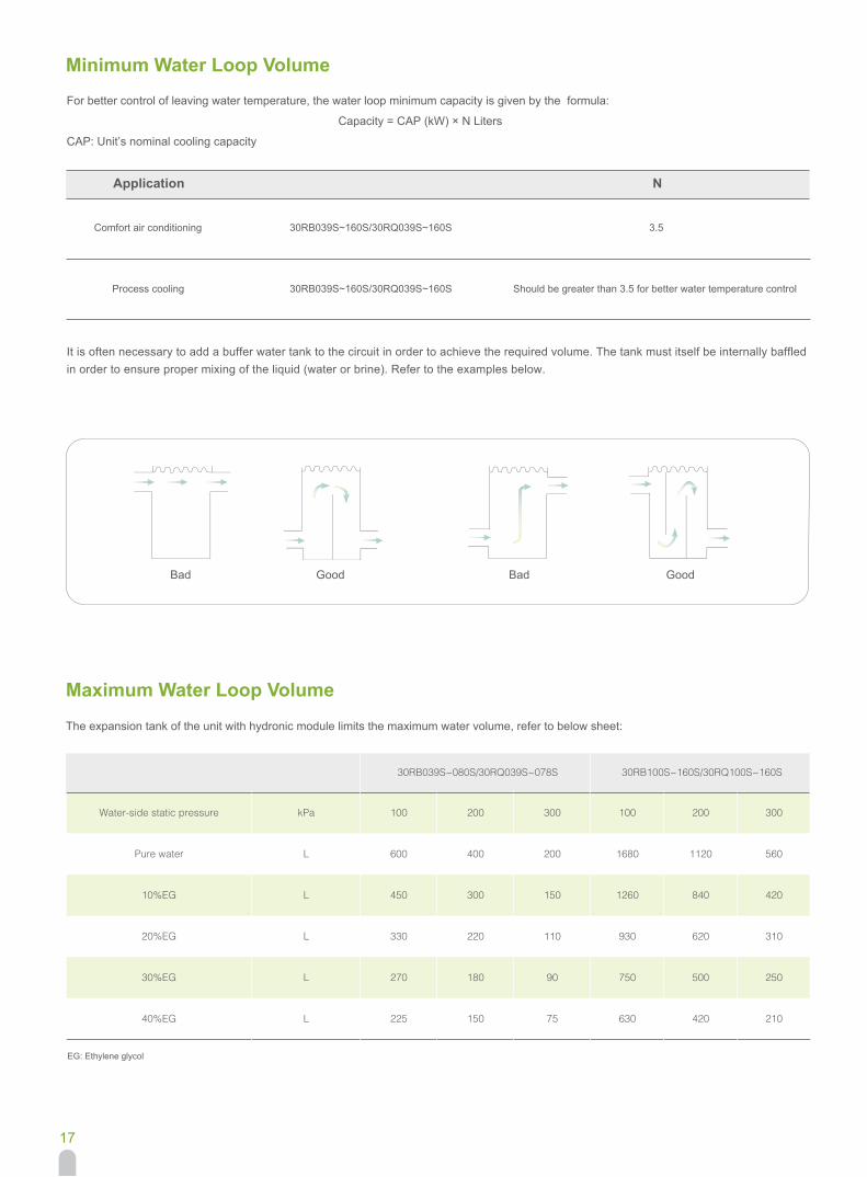
For better control of leaving water temperature, the water loop minimum capacity is given by the formula: Capacity = CAP (kW) × N Liters
CAP: Unit’s nominal cooling capacity
It is often necessary to add a buffer water tank to the circuit in order to achieve the required volume. The tank must itself be internally baffled in order to ensure proper mixing of the liquid (water or brine). Refer to the examples below.
The expansion tank of the unit with hydronic module limits the maximum water volume, refer to below sheet: