36
Improved energy absorption capacity cylinder with high tech appearance. Air Cylinder Series MB ø32, ø40, ø50, ø63, ø80, ø100 1.8-1 CJ1 CJP CJ2 CM2 C85 C76 CG1 MB MB1 CP95 C95 C92 CA1 CS1

Improved energy absorption capacity cylinder with high tech appearance.
Air Cylinder
Series MB ø32, ø40, ø50, ø63, ø80, ø100
1.8-1
CJ1
CJP
CJ2
CM2
C85
C76
CG1
MB
MB1
CP95
C95
C92
CA1
CS1

Series MB, MBW, MBK,
Improved cushion capacity"Floating" cushion seal design eliminates piston rod"bouncing" due to cracking pressure at beginning ofstroke.
Increased kineticenergy absorptionElevated cushion volume and the adoption of anew cushion seal design permit about 30% moreallowable kinetic energy over the CA1 series.In addition, service life of cushion seal is about 5times greater.
Compact and lightweightdesignThe square cover is made more compact thanthe CA1 series. In addition, die cast covers yield10 to 25% weight reduction over the CA1 series.
Minimal rod deflectionImproved bushing and piston rod dimensional accuracyachieves tighter clearances and reduced piston roddeflection.
Accurate mountingThe cylinder cover and mounting bracket withhigh dimensional accuracy simplifies installationand extends service life.
Double acting non-rotating rod
Double acting double rod
Double acting single rod
1.8-2

MBQ , MBBEasy adjustment of cushion valveAdjustment of the cushion valve is made with a hex. wrenchallowing for easy fine adjustment.The cushion valve is recessed in the cover.
End lock style
ø32, ø40, ø50, ø63, ø80, ø100
Port
D-A53D-A54D-A56D-A64D-A67D-A59W(2 colour indication)
3 wire D-F59 D-F5P
2 wire D J59
3 wire D-F59W D-F5PW (2 colour indication) 4 wire D F59F D F5LF (2 colour indication)
2 wire D-J59W D-F5BA (2 colour indication) 3 wire D F5NT
GrommetGrommetMounting
Applicable auto switchSolid state switchReed switchStyle
Tie rodmounting
Single rodSeries MB
Double rodSeries MBW
Non-rotating rodSeries MBK
Low frictionSeries MBQ
End lockSeries MBB
Sta
nd
ard
/Do
ub
le a
ctin
g
JIS Symbol
JIS Symbol
JIS Symbol
JIS Symbol
32
40
50
63
80
100
BasicAxial footFront flangeRear flangeSingle clevisDouble clevisCentre trunnion
BasicFootFlangeCentre trunnion
BasicAxial footFront flangeRear flangeSingle clevisDouble clevisCentre trunnion
StandardRod end nutOptionKnuckle joint pin Single knuckle jointDouble knuckle jointTrunnion pivot bracket
BasicAxial footFront flangeRear flangeSingle clevisDouble clevisCentre trunnion
StandardRod end nutOptionKnuckle joint pinClevis pinSingle knuckle jointDouble knuckle jointTrunnion pivot bracketDouble clevis pivot bracket
BasicAxial footFront flangeRear flangeSingle clevisDouble clevisCentre trunnion
StandardRod end nutLocking release bolt (N only)OptionKnuckle joint pinClevis pinSingle knuckle jointDouble knuckle jointTrunnion pivot bracketDouble clevis pivot bracket
Bore50 100 150 200 300 400 500
25 75 125 175 250 350 450 600700
800
Built-i
n-m
agne
t
Rod b
oot
Mou
nting
Acces
sorie
s
P.1.8-6
P.1.8-16
P.1.8-20
P.1.8-24
P.1.8-30
Standard stroke (mm) StandardRod end nutOptionKnuckle joint pinClevis pinSingle knuckle jointDouble knuckle jointTrunnion pivot bracketDouble clevis pivot bracket
StandardRod end nutOptionKnuckle joint pinClevis pinSingle knuckle jointDouble knuckle jointTrunnion pivot bracketDouble clevis pivot bracket
(1)
(1)
Note 1) Standard stroke for MBK series is below 700.
Variations
Low friction
CJ1
CJP
CJ2
CM2
C85
C76
CG1
MB
MB1
CP95
C95
C92
CA1
CS1
1.8-3

1.8-4

CJ1
CJP
CJ2
CM2
C85
C76
CG1
MB
MB1
CP95
C95
C92
CA1
CS1
q Do not open the cushion valve beyond the stopper.
Crimping (ø32) or a snap ring (ø40 to ø100) is provided to
prevent the accidental removal of the cushion valve. Do not
open the valve beyond the mechanism. If air is supplied, the
cushion valve may shoot out from the cover.
Adjustment
Warning
q Avoid using the air cylinder in such a way that more than allowable rotational torque would be applied to the piston rod.
If rotational torque is applied, the non-rotating guide will
deform, thus affecting the non-rotating accuracy.
Handling
Caution
q To screw a bracket or a nut onto the threaded portion at the tip of the piston rod, make sure to retract the piston rod entirely, and place a wrench over the flat portion of the rod that protrudes. To tighten, take precautions to prevent the tightening torque from being applied to the non-rotating guide.
Mounting/Piping
Caution
Bore (mm) Cushion valve Width across flats
Width across flats
Socket wrench
32, 40, 50
63, 80, 100
MB-32-10-C1247
MB-63-10-C1250
JIS 4648Hexagonal spanner wrench 2.52.5
4 JIS 4648Hexagonal spanner wrench 4
w Use the air cushion at the end of cylinder stroke. Select the cylinder with bumper "N" if cushion valve is to be fully opened.Tie rods or piston assembly may be damaged if neither air cushion nor bumper is utilized.
e When replacing mounting bracket, use a socket wrench.
Bore (mm) BoltTighteningtorque (Nm)
32, 40
50, 63
MB-32-48-C1247
MB-50-48-C1249
MB-80-48AC1251
MB-80-48BC1251
4
80,
100
Foot
Other
5
6
5.1
11
25
r There is no mounting interchangeability with CA1 series.
Non-rotating rod (Double acting Single rod)
1.8-5
Series MB/Precautions Be sure to read before handling. Refer to p.0-39 to 0-46 for Safety Instructions, actuator precautions and auto switch precautions.

Applicable Auto Switches/Tie Rod Mounting
Special functionStyle Electricalentry
Grommet
Ind
icat
or
Wiring(Output)
2 wire
3 wire(Equiv. to NPN)
Load voltage
≤ 200V
——
ACDC
Lead wire length∗(m)
0.5(–)
3(L)
5(Z)
—
—
—
—
—
ICcircuit
ICcircuit
ICcircuit
ICcircuit
ICcircuit
Applicable
loadAuto switch
model
Yes
——
100V, 200V
——
——
5V
12V
12V
5V, 12V
——
24V
Yes
Diagnostic output (2 colour)
With timer
Diagnostic indication(2 colour)
——
Yes
2 wire
3 wire (NPN)
3 wire (PNP)
4 wire(NPN)
24V
5V, 12V
12V —— ——
——
Ree
d s
wit
chS
olid
sta
te s
wit
ch
Latch diagnostic output(2 colour)
———
3 wire (NPN)
——A53
A54
A67
A64
A59W
F59
F5P
J51
J59
F59W
F5PW
J59W
F5BA
F5NT
F59F
F5LF
A56
Built-in magnet
Mounting
Bore size
MDB
Stroke (mm)Refer to standard stroke table.
BLFGCDT
——
——
5V, 12V
5V, 12V
No
Water resist (2 colour)
Diagnostic indication (2 colour)
——
Rod boot/Cushion
RelayPLC
RelayPLC
100V, 200V——
——
12V
——
24V
——
3 wire (PNP)
2 wire
3 wire (NPN)
Grommet
How to Order
Standard
With auto switch
MB
——
12V
3240506380100
32mm40mm50mm63mm80mm
100mm
Basic/Without bracketAxial foot
Front flangeRear flangeSingle clevisDouble clevis
Center trunnion
—JK—N (1)
NoneNylon tarpaulin
Heat resistant tarpaulinBoth ends
None
Rod boot
Cushion
L 32 50
50L 32
Mounting Bracket Part No.
Note 1) Two foot brackets required for one cylinder. ∗ Accessories for each mounting bracket are as follows.
Foot, Flange, Single clevis: Mounting boltsDouble clevis: Clevis pin, Cotter pinRefer to p.1.8-13 for details.
Auto Switch Mounting Bracket Part No.Bore size (mm) 32, 40
BT-03
50, 63
BT-05
80, 100
BT-06Mounting bracket
A set of following stainless steel mounting screws is attached. (A mounting bracket itself is not attached. Please order it separately.)
BBA1: D-A5/A6/F5/J5 types∗"D-F5BA" switch is set on the cylinder with the screws above when shipped. When a switch only is shipped, "BBA1" screws are attached.
Foot
Flange
Single clevis
Double clevis
(1)
Bore size (mm) 32
MB-L03
MB-F03
MB-C03
MB-D03
40
MB-L04
MB-F04
MB-C04
MB-D04
50
MB-L05
MB-F05
MB-C05
MB-D05
63
MB-L06
MB-F06
MB-C06
MB-D06
80
MB-L08
MB-F08
MB-C08
MB-D08
100
MB-L10
MB-F10
MB-C10
MB-D10
Note 1) Model without air cushion is designed to include rubber bumpers. The overall length is longer than the cylinder with air cushions because the bumpers are attached to the both sides of the piston as follows.ø32, ø40: +6mm, ø50, ø63: +8mm,ø80, ø100: +10mm
∗Refer to p.5.3-2 for further information on auto switch.
∗ Lead wire length 0.5m······ – (Example): A533m········· L (Example): A53L5m········· Z (Example): A53Z
∗∗ Solid state switches marked with " " are manufactured ∗∗ upon receipt of order.
—S3n
213n
Number ofauto switches
Auto switch/Tie rod mounting
∗ Refer to table below for selection of applicable auto switch.
— Without auto switch
A53
1.8-6
Air Cylinder/Standard: Double Acting Single Rod
Series MB ø32, ø40, ø50, ø63, ø80, ø100

CJ1
CJP
CJ2
CM2
C85
C76
CG1
MB
MB1
CP95
C95
C92
CA1
CS1
SpecificationsBore size (mm)
Action
Fluid
Proof pressure
Max. operating pressure
Min. operating pressure
Ambient and fluid temperature
Lubrication
Operating piston speed
Allowable stroke tolerance
Cushion
Thread tolerance
Port size
Mounting
Double acting single rod
Air
1.5MPa
1.0MPa
0.05MPa
Without auto switch: –10 to 70°C (No freezing)
With auto switch: –10 to 60°C (No freezing)
Not required (Non-lube)
50 to 1000mm/s
up to 250: , 251 to 1000: ,1001 to 1500:
Both ends (Air cushion)
JIS class 2
Basic, Foot, Front flange, Rear flange,
Single clevis, Double clevis, Center trunnion
32 40 63 100
+1.0 0
Standard Stroke
32
40
50
63
80
100
Bore(mm)
25, 50, 75, 100, 125, 150, 175, 200, 250, 300, 350, 400, 450, 500
25, 50, 75, 100, 125, 150, 175, 200, 250, 300, 350, 400, 450, 500
25, 50, 75, 100, 125, 150, 175, 200, 250, 300, 350, 400, 450, 500, 600
25, 50, 75, 100, 125, 150, 175, 200, 250, 300, 350, 400, 450, 500, 600
25, 50, 75, 100, 125, 150, 175, 200, 250, 300, 350, 400, 450, 500, 600, 700, 800
25, 50, 75, 100, 125, 150, 175, 200, 250, 300, 350, 400, 450, 500, 600, 700, 800
Standard stroke (mm)
50 80
+1.4 0
+1.8 0
(1)
Rc(PT)1/8 Rc(PT)1/4 Rc(PT)1/4 Rc(PT)3/8 Rc(PT)3/8 Rc(PT)1/2
Note 1) When requesting a cylinder without air cushion, cylinder utilizes rubber bumpers which increases cylinders overall length.
Max.stroke
700
800
1200
1200
1400
1500
Intermediate strokes are available.
Accessories
Mounting
Standard
Option
Rod end nut
Clevis pin
Single knuckle joint
Double knuckle joint
(with pin)
Rod boot
Basic FootFrontflange
Rearflange
Singleclevis
Doubleclevis
Centertrunnion
— — — — — —
Material of Rod BootSymbol
J
K
Material
Nylon tarpaulin
Heat resistant tarpaulin
Max. ambient temp.
60°C
110°C∗ Max. ambient temperature for rod boot itself.
Minimum Cylinder Stroke for Mounting Auto SwitchesRefer to p.1.8-14 for "Minimum Cylinder Stroke for Mounting Auto Switches".
JIS SymbolDouble acting
∗
Made to Order
Refer to p.5.4-1 for made to orderproducts of series MB.
OrderMade
1.8-7
Standard: Double Acting Single Rod Series MB

Theoretical ForceBore size
(mm)
32
40
50
63
80
100
12
16
20
20
25
30
OUT
IN
OUT
IN
OUT
IN
OUT
IN
OUT
IN
OUT
IN
804
691
1257
1056
1963
1649
3117
2803
5027
4536
7854
7147
0.2
161
138
251
211
393
330
623
561
1005
907
1571
1429
0.3
241
207
377
317
589
495
935
841
1508
1361
2356
2144
0.4
322
276
503
422
785
660
1247
1121
2011
1814
3142
2859
0.5
402
346
629
528
982
825
1559
1402
2514
2268
3927
3574
0.6
482
415
754
634
1178
989
1870
1682
3016
2722
4712
4288
0.7
563
484
880
739
1374
1154
2182
1962
3519
3175
5498
5003
0.8
643
553
1006
845
1570
1319
2494
2242
4022
3629
6283
5718
0.9
724
622
1131
950
1767
1484
2805
2523
4524
4082
7069
6432
1.0
804
691
1257
1056
1963
1649
3117
2803
5027
4536
7854
7147
Rod diameter(mm)
Operatingdirection
Piston area(mm2)
Operating pressure (MPa)
(Unit: N) OUT IN
Note) Theoretical force (N)=Pressure (MPa) X Piston area (mm2)
Weight/Aluminum TubeBore size (mm)
Basic weight
Basic
Foot
Flange
Single clevis
Double clevis
Trunnion
All mounting bracket
Single knuckle joint
Double knuckle joint (with pin)
32
0.50
0.62
0.79
0.75
0.76
0.79
0.11
0.15
0.22
Additional weight per 50 stroke
Accessories
40
0.69
0.83
1.06
0.92
0.96
1.05
0.16
0.23
0.37
50
1.19
1.41
1.64
1.53
1.62
1.67
0.26
0.26
0.43
63
1.47
1.75
2.26
2.10
2.26
2.27
0.27
0.26
0.43
80
2.73
3.23
4.18
3.84
4.13
4.28
0.42
0.60
0.87
100
3.70
4.36
7.01
6.87
7.39
7.37
0.56
0.83
1.27
(kg)
Calculation example: MBB32-100 (Basic, ø32, 100st) Basic weight ·········· 0.50 (Basic, ø32) Additional weight ··· 0.11/50 stroke Cylinder stroke ······ 100 stroke 0.50+0.11X100/50=0.72kg
Allowable Kinetic Energy
100 300 1000 2000500
900
500
300
200
10080
50
30
20
10
ø32
ø40
ø100
ø80
ø63
ø50
5
Cushion Mechanism Refer to p.5.6-5 for details of maximum kineticenergy absorption and air cushions.
0.03
0.16
0.03
0.21
0.05
0.33
0.07
0.37
0.11
0.56
0.13
0.72
Additional weight to the basic weight∗
Additional weight per 50 strokeSquare tube
Max. acting speed (mm/s)
Load
wei
ght (
kg)
Example: Load limit at rod end when air cylinder ø63 is actuated with max. actuating speed 500mm/s. See the intersection of lateral axis 500mm/s and ø63 line, and extend the intersection to left. Thus the allowable load is 80kg.
1.8-8
Series MB
CJ1
CJP
CJ2
CM2
C85
C76
CG1
MB
MB1
CP95
C95
C92
CA1
CS1
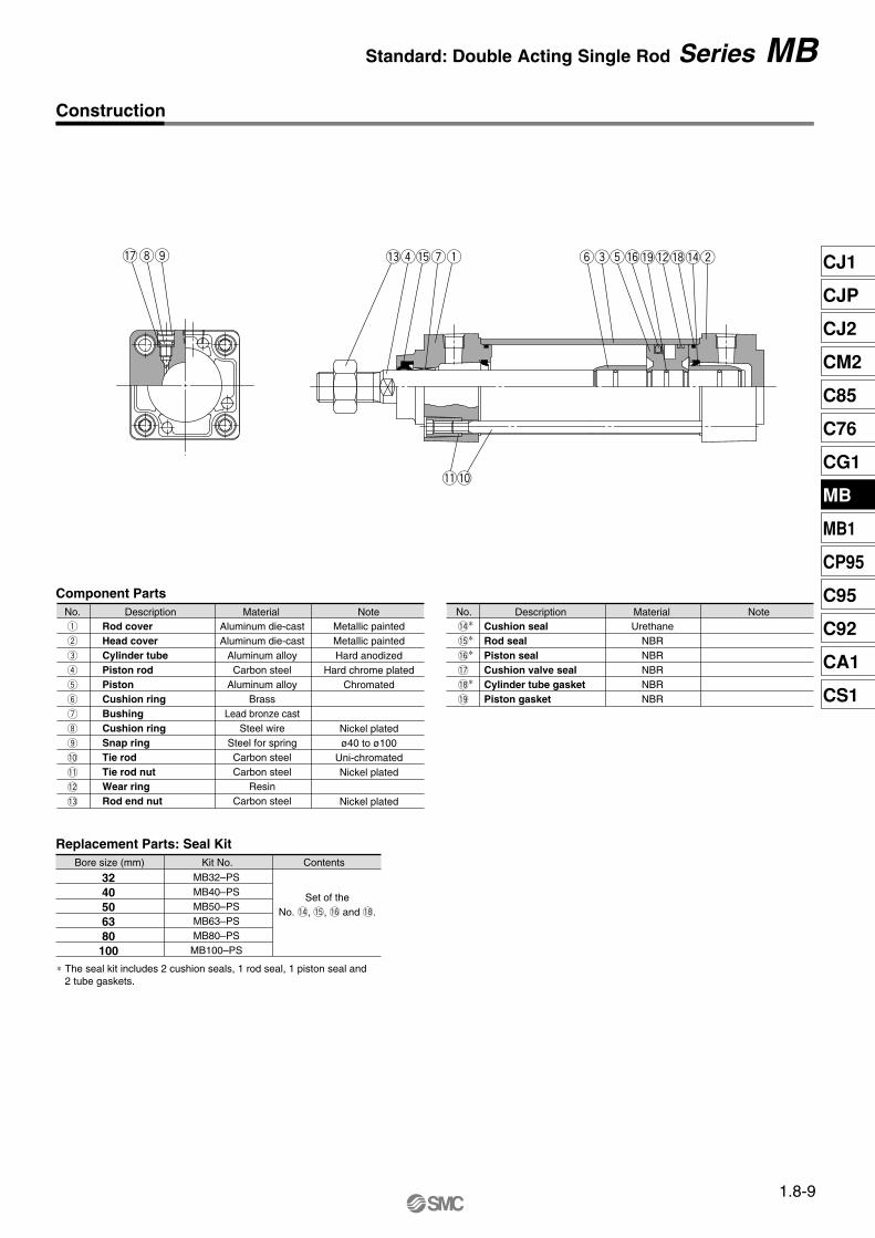
Component Parts
Replacement Parts: Seal Kit
No.q
w
e
r
t
y
u
i
o
!0
!1
!2
!3
DescriptionAluminum die-castAluminum die-cast
Aluminum alloyCarbon steel
Aluminum alloyBrass
Lead bronze castSteel wire
Steel for springCarbon steelCarbon steel
ResinCarbon steel
Rod coverHead coverCylinder tubePiston rodPistonCushion ringBushingCushion ringSnap ringTie rodTie rod nutWear ringRod end nut
Material Note
MB32–PSMB40–PSMB50–PSMB63–PSMB80–PSMB100–PS
Set of theNo. !4, !5, !6 and !8.
3240506380
100
Metallic paintedMetallic paintedHard anodized
Hard chrome platedChromated
Nickel platedø40 to ø100
Uni-chromatedNickel plated
Nickel plated
No. !4∗
!5∗
!6∗
!7
!8∗
!9
DescriptionCushion sealRod sealPiston sealCushion valve sealCylinder tube gasketPiston gasket
UrethaneNBRNBRNBRNBRNBR
Material Note
∗ The seal kit includes 2 cushion seals, 1 rod seal, 1 piston seal and 2 tube gaskets.
Bore size (mm) Kit No. Contents
Construction
!7io !3r!5uq yet!6!9!2!8!4w
!1!0
1.8-9
Standard: Double Acting Single Rod Series MB

Without Mounting Bracket
101418182226
3240506380100
up to 500up to 500up to 600up to 600up to 750up to 750
Stroke range(mm)
Bore size(mm)
Widthacrossflats
19.52732323737
Effectivethread length
135139156156190190
ZZ∗
475158587272
H
6.59
10.5121415
W
4459
11.517
V
84849494
114114
S∗
1/81/41/43/83/81/2
P
2727
31.531.53838
N
M10 X 1.25M14 X 1.5M18 X 1.5M18 X 1.5M22 X 1.5M26 X 1.5
MM
6677
1010
K
M6M6M8M8
M10M10
J
445555
MB
161616161616
MA
1314
15.516.51919
G
131314142020
F
303540454555
Ee11
121620202530
D
32.538
46.556.57289
4652657595114
223035354040
A
6380100
164200200
ZZ
102124124
S
324050
Bore size(mm)
Bore size(mm)
141145164
ZZ
9090
102
S
Without air cushion
3240506380
100
Bore size(mm)
12.512.512.512.512.512.5
With rod boot
364151515661
e
232325252929
f1 to 50
252525252525
51 to 100
37.537.537.537.537.537.5
101 to 150
505050505050
151 to 200
l
757575757575
201 to 300
100100100100100100
301 to 400
125125125125125125
401 to 500
——
150150150150
501 to 600
————
175175
601 to 700
————
200200
701 to 800
73818989101101
1 to 50
8694102102114114
51 to 100
98106114114126126
101 to 150
111119127127139139
151 to 200
h
136144152152164164
201 to 300
161169177177189189
301 to 400
186194202202214214
401 to 500
——
227227239239
501 to 600
————
264264
601 to 700
————
289289
701 to 800
(mm)
With Mounting Bracket
Foot/(L)
∗ Refer to Basic/(B) for other dimensions and with rod boot.
3240506380100
Bore size(mm)
168176198201240244
ZZ
134138156156184188
LS
Without air cushion
3240506380
100
Bore size(mm)
Strokerange
700800
1000100010001000
222427273032
X
91111141416
Y
799121214
LD
303340455565
LH
128132148148174178
LS∗
3.23.23.23.64.54.5
LT
323846567289
LX
535972.582.5
102.5122
LY
50557080
100120
LZ
162170190193230234
ZZ∗
(mm)Foot
ZZ + Stroke
LS + Stroke
XY X Y
LT 4-øLD
Basic/(B)
Cushion valve Port
LZ
LH
LY
LX
CB
Cushion valve
WVPort
CB
øE
h
9 fl
13
øe
With rod boot
ZZ + Stroke
S + StrokeH
A K F NMAMBEffective
thread
N
2-Rc(PT)PMMG
2 X 4-J
G
øE
øD
∗Model without air cushion is designed to include rubber bumpers. The overall length is longer than the cylinder with air cushion as follows because the bumpers are attached to the both sides of the piston;
ø32, ø40: +6mm, ø50, ø63: +8mm, ø80, ø100: +10mm
∗Model without air cushion is designed to include rubber bumpers. The overall length is longer than the cylinder with air cushion as follows because the bumpers are attached to the both sides of the piston;ø32, ø40: +6mm, ø50, ø63: +8mm, ø80, ø100: +10mm
1.8-10
Series MB

CJ1
CJP
CJ2
CM2
C85
C76
CG1
MB
MB1
CP95
C95
C92
CA1
CS1
Front flange/(F)
With Mounting Bracket
3240506380100
Rear flange/(G)
Single clevis/(C)
Double clevis/(D)
Centre trunnion/(T)
Front flangeBore size
(mm)Strokerange
up to 700up to 800up to 1000up to 1000up to 1000up to 1000
B
50557080
100120
FD
7999
1214
FE
332244
FT
101012121616
FX
647290100126150
FY
323645506375
FZ
7990110120153178
Fd
2531
38.539.545.554
Without air cushionBore size
(mm) ZZ
147151172212
3240
50/6380/100
3240506380100
Rear flange
up to 500up to 500up to 600up to 600up to 750up to 750
B
50557080100120
FD
7999
1214
FT
101012121616
FX
647290
100126150
FY
323645506375
FZ
7990110120153178
ZZ∗
141145164164202202
Without air cushion
ZZ
170.5175205261
3240
50/6380/100
Z
160164190238
3240506380
100
Single clevis
up to 500up to 500up to 600up to 600up to 750up to 750
L
232330304242
RR
10.51115152323
U
131317172626
CD
101014142222
141420203030
Z∗
154158182182228228
ZZ∗
164.5169197197251251
H10 CX–0.1–0.3
Without air cushion
ZZ
170.5175205261
3240
50/6380/100
Z
160164190238
3240506380100
Double clevis
up to 500up to 500up to 600up to 600up to 750up to 750
L
232330304242
RR
10.51115152323
U
131317172626
101014142222
141420203030
Z∗
154158182182228228
ZZ∗
164.5169197197251251
CD H10 CX+0.3+0.1 CZ
282840406060
Without air cushion
3240
50/6380/100
Z
9296
109134
3240506380100
Centre trunnion
up to 500up to 500up to 600up to 600up to 750up to 750
121616202025
TT
172222283440
Z∗∗
8993105105129129
TZ
7495
107130150182
TX
50637590110132
TDe8
FXFZ
B FY
PortCushion valve4-øFD
FTZZ + Stroke
CX
PortCushion valve
U
ZZ + Stroke
øCDH10
LZ + Stroke RR
Z + 1/2 Stroke
TT
FXFZ
PortCushion valve4-øFD
B FY
TY
49587187
110136
FTFE
øF
d
CX
CZ
PortCushion valve
TXTZ
TY
øT
De8
PortCushion valve
U
ZZ + Stroke
LZ + Stroke RR
øCDH10
Bore size(mm)
Strokerange
Bore size(mm)
Strokerange
Bore size(mm)
Strokerange
Bore size(mm)
Strokerange
Bore size(mm)
Bore size(mm)
Bore size(mm)
∗ Front/Rear flange, Single/Double clevisModel without air cushion is designed to include rubber bumpers. The overall length is longer than the cylinder with air cushion as follows because the bumpers are attached to the both sides of the piston;ø32, ø40: +6mm, ø50, ø63: +8mm, ø80, ø100: +10mm
∗∗Centre trunnionModel without air cushion is designed to include rubber bumpers. The overall length is longer than the cylinder with air cushion as follows because the bumpers are attached to the both sides of the piston;ø32, ø40: +3mm, ø50, ø63: +4mm,ø80, ø100: +5mm
1.8-11
Standard: Double Acting Single Rod Series MB
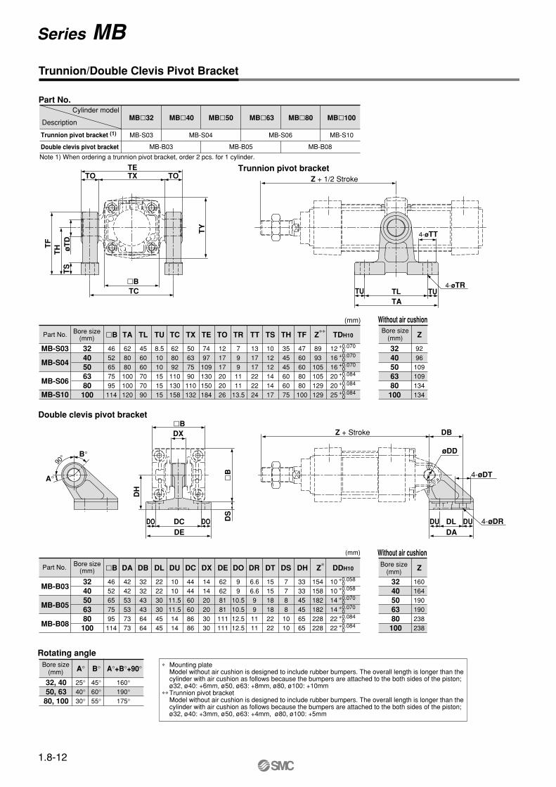
Trunnion/Double Clevis Pivot Bracket
MB-S03
MB-S04
MB-S06
MB-S10
Bore size(mm)Part No.
8993105105129129
Z∗∗
4760608080100
TF
354545606075
TH
101212141417
TS
131717222224
7991111
13.5
TR
4652657595
114
628080100100120
TA
Cylinder model
Description
Trunnion pivot bracket (1)
Double clevis pivot bracket
Part No.
MB-S03
MB-B03
MB-S04
MB-B05
MB-S06
MB-B08
MB-S10
3240506380100
456060707090
TL
8.51010151515
TU
628092110130158
TC
50637590110132
TX
121717202026
TO TT
7497109130150184
TE
121616202025
TDH10
+0.070 0+0.070 0+0.070 0+0.084 0+0.084 0+0.084 0
Bore size(mm) Z
9296
109109134134
3240506380
100
Without air cushion
Double clevis pivot bracket
MB-B03
MB-B05
MB-B08
Bore size(mm)Part No.
154158182182228228
Z∗
333345456565
DH
7788
1010
DS
151518182222
DT
6.66.6991111
99
10.510.512.512.5
DO
4652657595114
424253537373
DA
3240506380100
323243436464
DB
222230304545
DL
1010
11.511.51414
DU
444460608686
DC
62628181111111
DE DR
141420203030
DX
101014142222
DDH10
+0.058 0+0.058 0+0.070 0+0.070 0+0.084 0+0.084 0
Bore size(mm) Z
160164190190238238
3240506380100
Without air cushion(mm)
Bore size(mm) A°
25°40°30°
32, 4050, 6380, 100
B°
45°60°55°
A°+B°+90°
160°190°175°
Rotating angle
Trunnion pivot bracket
TLTA
TU TU4-øTR
4-øTT
Z + 1/2 Stroke
B°
A°
90°
Note 1) When ordering a trunnion pivot bracket, order 2 pcs. for 1 cylinder.
Z + Stroke
øDD
DADLDU DU 4-øDR
4-øDT
DB
(mm)
B
MB32 MB40 MB50 MB63 MB80 MB100
TETXTO TO
TY
TC
TS
øT
DT
HTF
B
DEDCDO DO D
S
DX
DH
B
B
B
∗ Mounting plateModel without air cushion is designed to include rubber bumpers. The overall length is longer than the cylinder with air cushion as follows because the bumpers are attached to the both sides of the piston;ø32, ø40: +6mm, ø50, ø63: +8mm, ø80, ø100: +10mm
∗∗ Trunnion pivot bracket Model without air cushion is designed to include rubber bumpers. The overall length is longer than the cylinder with air cushion as follows because the bumpers are attached to the both sides of the piston;ø32, ø40: +3mm, ø50, ø63: +4mm, ø80, ø100: +5mm
1.8-12
Series MB

CJ1
CJP
CJ2
CM2
C85
C76
CG1
MB
MB1
CP95
C95
C92
CA1
CS1
Bore size(mm)Part No. Part No.
3240
50/6380100
NT-03NT-04NT-05NT-08NT-10
d
M10 X 1.25M14 X 1.5M18 X 1.5M22 X 1.5M26 X 1.5
H
68
111316
B
1722273241
C
19.625.431.237.047.3
D
16.521263139
Bore size(mm)Part No.
3240
50/6380
100
I-03MI-04MI-05MI-08MI-10M
A
4050648080
A1
1419242626
E1
2022284040
L1
3040506060
MM
M10 X 1.25M14 X 1.5M18 X 1.5M22 X 1.5M26 X 1.5
R1
1212.516.523.523.5
U1
1619243434
NDH10 NX
Bore size (mm)Clevis Knuckle
32/4050/6380/100
CD-M03CD-M05CD-M08
Dd9 L
446082
l
365172
m
44.55
344
Applicable cotter pin
ø3 X 18 lø4 X 25 lø4 X 35 l
101422
–0.040–0.076–0.050–0.093–0.065–0.117
d(Through
hole diameter)
(1)
Note 1) When using cotter pin, flatwasher is used together.
1010142222
+0.058 0+0.058 0+0.070 0+0.084 0+0.084 0
1414203030
–0.10–0.30–0.10–0.30–0.10–0.30–0.10–0.30–0.10–0.30
Bore size(mm)Part No.
3240
50/6380
100
Y-03MY-04MY-05MY-08MY-10M
E1
2022284040
L1
3040506565
MM
M10 X 1.25M14 X 1.5M18 X 1.5M22 X 1.5M26 X 1.5
R1
1011142020
U1
1619243434
NDH10 NZ
1010142222
+0.058 0+0.058 0+0.070 0+0.084 0+0.084 0
2828406060
–0.10–0.30–0.10–0.30–0.10–0.30–0.10–0.30–0.10–0.30
NX
1414203030
+0.30+0.10+0.30+0.10+0.30+0.10+0.30+0.10+0.30+0.10
Note) For a double clevis, a clevis pin (with a retaining ring) is equipped as standard.
Single clevis
Double clevis
Single knuckle joint
Double knuckle joint
Singleclevis
Doubleclevis
Singleknuckle joint
Doubleknuckle joint
Pivotbracket
No. Appearance
–
e
–
u
q
–
t
–
–
r
–
i
w
–
y
–
–
o
–
!0
Bracket forworkBracket
for cylinder
q
w
e
r
t
y
u
i
o
!0
No. Appearance
Single clevis + Double clevis
Single clevis + Double knuckle joint
Double clevis + Single clevis
Double clevis + Single knuckle joint
Single knuckle joint + Double clevis
Single knuckle joint + Double knuckle joint
Double knuckle joint + Single clevis
Double knuckle joint + Single knuckle joint
Double clevis + Pivot bracket
Double knuckle joint + Pivot bracket
Available combinations ··········································· Refer to below picture together.
Dimensions for Accessories
Combinations of Support Brackets
Single knuckle joint
Rod end nut(Standard)
Double knuckle joint
Knuckle joint pinClevis pin
B
2-ød
C
d
DH
30°
Llm
øD
d9
RR1
L1
U1
øNDH10MM
NZ
NX
øE
1
AL1
NX
MM øNDH1045° RR1
U1A1
øE
1
1.8-13
Standard: Double Acting Single Rod Series MB

Electrical entry (Function)
Grommet
Grommet (2 colour)
Grommet
Grommet (2 colour)
Grommet (2 colour, Water resistant)
Grommet (2 colour, diagnostic output)
Grommet (Timer)
Page
5.3-17
5.3-27
5.3-37
5.3-46
5.3-58
5.3-54
5.3-61
15
20
15
15
10
15
10
15
10
ø32 ø40 ø50 ø63 ø80 ø100 ø32 ø40 ø50 ø63 ø80 ø100
20
25
25
25
25
60
60
60
70
70
70
70
75
75
80
85
85
95
90
105
110
110
120
120
110
115
115
125
125
115
120
120
130
130
Reed switch Solid state switch
32
40
50
63
80
100
D-A5/D-A6 D-A59W D-F5NTL
A
0.5
0.5
1
1
4
4
B
0
0
0
0
2.5
2.5
A
4.5
4.5
5
5
8
8
B
2
2
2.5
2.5
6.5
6.5
A
7
7
7.5
7.5
10.5
10.5
B
4.5
4.5
5
5
9
9
A
11
11
11.5
11.5
14.5
14.5
B
8.5
8.5
9
9
13
13
A
12
12
12.5
12.5
15.5
15.5
B
9.5
9.5
10
10
14
14
32
40
50
63
80
100
D-A5D-A6
D-A59W
Ht
24.5
27.5
34.5
39.5
46.5
55
Hs
35
38.5
43.5
48.5
55
62
Ht
25
27.5
34
39
46.5
55
Hs
32.5
36.5
41
46
52.5
59.5
A B
≅ Hs
≅ H
t
≅ Hs
≅ H
t
A B
D-F5, D-J5D-F5W, D-J59WD-F5BAL, D-F5NTL
D-F5WD-J59WD-F5BA
D-F5D-J5
Applicable Auto Switch
Minimum Cylinder Stroke for Mounting Auto Switches
Auto Switch Mounting Position/Mounting Height
Auto Switch Mounting Position Auto Switch Mounting Height
Style
Be sure to read before handling. Refer to p.0-44 to 0-46 for precautions on the auto switch.
Auto switch model
Auto switch model
Bore size
(mm)
Bore size
(mm)
2 pcs. (On differentface or same face)
Support bracket except center trunnion Center trunnionNumber ofauto switches
Reed
Solid state
Style
1 pc.
2 pcs. (On differentface or same face)
1 pc.
2 pcs. (On differentface or same face)
1 pc.
2 pcs. (On differentface or same face)
1 pc.
2 pcs. (On differentface or same face)
1 pc.
Ree
d sw
itch
Sol
id s
tate
sw
itch
Precautions
(mm)
(mm) (mm)
Tie Rod MountingD-A5l/A6l
D-A59W
D-F5l/J5l
D-F5lW/J59W
F5BAL
D-F5lF
D-F5NTL
D-A5, D-A6
D-A59W
D-F5/ J5
D-F5NTL
D-F5WD-J59WD-F5BAL D-F5FD-F5LF
1.8-14
Series MDBAuto Switch SpecificationsRefer to p.5.3-2 for details of the auto switch.

CJ1
CJP
CJ2
CM2
C85
C76
CG1
MB
MB1
CP95
C95
C92
CA1
CS1
1.8-15

Applicable Auto Switches/Tie Rod Mounting
Special functionStyle Electricalentry
Grommet
Ind
icat
or
Wiring(Output)
2 wire
2 wire
2 wire
3 wire(Equiv. to NPN)
Load voltage
≤ 200V
——
ACDC
Lead wire∗(m)
0.5(—)
3(L)
5(Z)
Applicableload
Auto switchmodel
Yes
——
100V, 200V
——
——
5V
12V
12V
5V, 12V
——
24V
Yes
Diagnostic output (2 colour)
With timer
Diagnostic indication(2 colour)
——
Yes
3 wire (NPN)
3 wire (PNP)
3 wire (NPN)
3 wire (NPN)
4 wire (NPN)
3 wire (PNP)
24V
5V, 12V
12V —— ——
ICcircuit
ICcircuit
ICcircuit
ICcircuit
ICcircuit
——
Ree
d sw
itch
So
lid s
tate
sw
itch
Latch diagnostic output(2 colour)
———
—
—
—
—
—
——A53
A54
A67
A64
A59W
F59
F5P
J51
J59
F59W
F5PW
J59W
F5BA
F5NT
F59F
F5LF
A56
Built-in magnet
MountingBore size
MDBW
Stroke (mm)Refer to standard stroke table.
BLFT
——
——
5V, 12V
5V, 12V
No
Water resistant (2 colour)
Diagnostic indication (2 colour)
——
Rod boot/Cushion
RelayPLC
RelayPLC
100V, 200V——
——
12V
——
24V
——
Grommet
How to Order
Standard
With auto switch
MBW
——
12V
Basic/Without bracketFoot
FlangeCenter trunnion
3240506380
100
32mm40mm50mm63mm80mm100mm
—JJJK
KK—
(1)
NoneNylon tarpaulin (one end)
Nylon tarpaulin (both ends)Heat resistant tarpaulin (one end)Heat resistant tarpaulin (both ends)
Both endsNone
Note1) Model without air cushion is designed to include rubber bumpers. The overall length is longer than the cylinder with air cushions because the bumpers are attached to the both sides of the piston as follows.
ø32, ø40: +6mm, ø50, ø63: +8mm,
ø80, ø100: +10mm
Rod boot
Cushion
L
L
32
32
150
150
Auto Switch Mounting Bracket Part No.Bore size (mm) 32, 40
BT-03
50, 63
BT-05
80, 100
BT-06Mounting bracket
Mounting Bracket Part No.
A set of following stainless steel mounting screws is attached. (A mounting bracket itself is not attached. Please order it separately.)
BBA1: D-A5/A6/F5/J5 types∗"D-F5BA" switch is set on the cylinder with the
screws above when shipped. When a switch only is shipped, "BBA1" screws are attached.
32MB-L03
MB-F03
40MB-L04
MB-F04
50MB-L05
MB-F05
Bore size (mm)
Foot
Flange
∗ Two foot brackets required for one cylinder.
80MB-L08
MB-F08
100MB-L10
MB-F10
63MB-L06
MB-F06
∗Refer to p.5.3-2 for further information on the auto switch.
N
∗ Lead wire length
∗∗ Solid state switches marked with " " are manufacturedupon receipt of order.
0.5mm ····· – (Example): A533m ··········· L (Example): A53L5m ··········· Z (Example): A53Z
—S3n
213n
Number of auto switches
Auto switch/Tie rod mounting
∗ Refer to table below for selection of applicable auto switch.
— Without auto switch
A53
1.8-16
Air Cylinder/Standard: Double Acting Double Rod
Series MBW ø32, ø40, ø50, ø63, ø80, ø100

CJ1
CJP
CJ2
CM2
C85
C76
CG1
MB
MB1
CP95
C95
C92
CA1
CS1
SpecificationsBore size (mm)
Action
Fluid
Proof pressure
Max. operating pressure
Min. operating pressure
Ambient and fluid temperature
Lubrication
Operating piston speed
Allowable stroke tolerance
Cushion
Thread tolerance
Port size
Mounting
Double acting double rod
Air
1.5MPa
1.0MPa
0.05MPa
Without auto switch: –10 to 70°C (No freezing)
With auto switch: –10 to 60°C (No freezing)
Not required (Non-lube)
50 to 1000mm/s
up to 250: , 251 to 750:
Both ends (Air cushion)
JIS class 2
Basic, Foot, Flange, Centre trunnion
32 40 63 100
+1.0 0
Standard Stroke
32
40
50
63
80
100
Bore size(mm)
25, 50, 75, 100, 125, 150, 175, 200, 250, 300, 350, 400, 450, 500
25, 50, 75, 100, 125, 150, 175, 200, 250, 300, 350, 400, 450, 500
25, 50, 75, 100, 125, 150, 175, 200, 250, 300, 350, 400, 450, 500, 600
25, 50, 75, 100, 125, 150, 175, 200, 250, 300, 350, 400, 450, 500, 600
25, 50, 75, 100, 125, 150, 175, 200, 250,300, 350, 400, 450, 500, 600, 700, 800
25, 50, 75, 100, 125, 150, 175, 200, 250,300, 350, 400, 450, 500, 600, 700, 800
Standard stroke (mm)
Theoretical ForceBore(mm)
12
16
20
20
25
30
50 80
+1.4 0
Rc(PT)1/8 Rc(PT)1/4 Rc(PT)1/4 Rc(PT)3/8 Rc(PT)3/8 Rc(PT)1/2
Note 1) Absorbable kinetic energy by cushion mechanism is identical to double acting single rod. When requesting a cylinder without air cushion, cylinder utilizes rubber bumpers which increases cylinder overall length.
Intermediate strokes are available.
Operating pressure (MPa)
Accessories
Mounting
Standard
Option
Rod end nut
Single knuckle joint
Double knuckle joint (with pin)
Rod boot
Basic Foot FlangeCentre
trunnion
Material of Rod BootSymbol
J
K
Material
Nylon tarpaulin
Heat resistant tarpaulin
Max. ambient temp.
60°C
110°C∗ Max. ambient temperature for rod boot itself.
Minimum Cylinder Stroke for Mounting Auto SwitchesRefer to p.1.8-14 for "Minimum Cylinder Strokefor Mounting Auto Switches".
JIS SymbolDouble acting
32
40
50
63
80
100
IN/OUT
IN/OUT
IN/OUT
IN/OUT
IN/OUT
IN/OUT
691
1056
1649
2803
4536
7147
0.2
138
211
330
561
907
1429
0.3
207
317
495
841
1361
2144
0.4
276
422
660
1121
1814
2859
0.5
346
528
825
1402
2268
3574
0.6
415
634
989
1682
2722
4288
0.7
484
739
1154
1962
3175
5003
0.8
553
845
1319
2242
3629
5718
0.9
622
950
1484
2523
4082
6432
1.0
691
1056
1649
2803
4536
7147
Rod dia.(mm)
Operatingdirection
Piston area(mm2)
(Unit: N)OUTIN
Note) Theoretical force (N)=Pressure (MPa) X Piston area (mm2)
Weight/Aluminum TubeBore size (mm) 32
0.56
0.68
0.85
0.85
0.15
0.15
0.22
Basic weight
Additional weight per 50 stroke
Accessories
Basic
Foot
Flange
Trunnion
All mounting bracket
Single knuckle
Double knuckle (with pin)
40
0.79
0.93
1.16
1.15
0.24
0.23
0.37
50
1.34
1.56
1.79
1.82
0.34
0.26
0.43
63
1.65
1.93
2.44
2.45
0.35
0.26
0.43
80
3.11
3.61
4.56
4.66
0.61
0.60
0.87
100
4.14
4.8
7.45
7.81
0.84
0.83
1.27
(kg)
(1)
Calculation example: MBWB32-100 (Basic, ø32, 100st) Basic weight ··········· 0.56 (Basic, ø32) Additional weight ···· 0.15/50 stroke Cylinder stroke ······· 100 stroke 0.56+0.15X100/50=0.86kg
∗
0.03
0.20
0.03
0.29
0.05
0.41
0.07
0.45
0.11
0.75
0.13
1.0
Additional weight to the basic weight∗
Additional weight per 50 strokeSquare tube
Made to Order
Refer to p.5.4-1 for made to orderproducts of series MBW.
OrderMade
(1)
1.8-17
Standard: Double Acting Double Rod Series MBW

Construction
iu!5
Component Parts
Replacement Parts: Seal Kits
No.q
w
e
r
t
y
u
i
o
!0
!1
Description
Aluminum die castAluminum alloyCarbon steel
Aluminum alloyResin
Lead bronze castSteel wire
Steel for springCarbon steelCarbon steelCarbon steel
Rod coverCylinder tubePiston rodPistonCushion ringBushingCushion valveSnap ringTie rodTie rod nutRod end nut
Material Note
3240506380
100
Metallic paintedHard anodized
Hard chrome platedChromated
Nickel platedø40 to ø100
Uni-chromatedNickel platedNickel plated
No. !2∗
!3∗
!4∗
!5
!6∗
!7
!8
Description
Cushion sealRod sealPiston sealCushion valve sealCylinder tube gasketPiston gasketPiston retainer
UrethaneNBRNBRNBRNBRNBR
Urethane
Material Note
∗ The seal kit includes 2 cushion seals, 1 rod seal, 1 piston seal,and 2 tube gaskets.
Bore size (mm) Kit No. Contents
Set of theNo. !2, !3, !4 and !6.
!1e!3yq twr!4!8!7!2!6
o!0
MBW32–PSMBW40–PSMBW50–PSMBW63–PSMBW80–PS
MBW100–PS
1.8-18
Series MBW

CJ1
CJP
CJ2
CM2
C85
C76
CG1
MB
MB1
CP95
C95
C92
CA1
CS1
With Mounting Bracket
With Mounting Bracket
∗ Model without air cushion is designed to include rubber bumpers. The overall length is longer than the cylinder with air cushion as follows because the bumpers are attached to the both sides of the piston;ø32, ø40: +6mm, ø50, ø63: +8mm, ø80, ø100: +10mm
∗∗ Model without air cushion is designed to include rubber bumpers. The overall length is longer than the cylinder with air cushion as follows because the bumpers are attached to the both sides of the piston;ø32, ø40: +3mm, ø50, ø63: +4mm, ø80, ø100: +5mm
101418182226
up to 500up to 500up to 600up to 600up to 750up to 750
Stroke range Widthacross flats
Bore(mm)
19.52732323737
Eff. threadlength
178186210210258258
ZZ∗∗
475158587272
H
6.59
10.5121415
W
4459
11.517
V
84849494114114
S∗
1/81/41/43/83/81/2
P
2727
31.531.53838
N
M10 X 1.25M14 X 1.5M18 X 1.5M18 X 1.5M22 X 1.5M26 X 1.5
MM
6677
1010
K
M6M6M8M8M10M10
J
445555
MB
161616161616
MA
1314
15.516.51919
G
131314142020
F
303540454555
Ee11
121620202530
D
32.538
46.556.57289
4652657595114
223035354040
A
Withoutair cushion
3240506380100
Bore(mm)
12.512.512.512.512.512.5
With rod boot
364151515661
e
232325252929
f 1 to50
l
125125125125125125
——
150150150150
————
175175
————
200200
ZZ
∗ Refer to basic mounting/(B) for other dimensions and with rod boot.
3240506380
100
Bore(mm)
Bore(mm)
Bore(mm)
Strokerange
Strokerange
Strokerange
up to 500up to 500up to 600up to 600up to 750up to 750
222427273032
X
91111141416
Y
799
121214
LD
303340455565
LH
128132148148174178
LS∗
3.23.23.23.64.54.5
LT
323846567289
LX
5359
72.582.5102.5122
LY
50557080
100120
LZ
Foot
184192218218268268
ZZ
9090102102124124
S
51 to 100
101 to 150
151 to 200
201 to 300
301 to 400
401 to 500
501 to 600
601 to 700
701 to 800
1 to 50
51 to 100
101 to 150
151 to 200
201 to 300
301 to 400
401 to 500
501 to 600
601 to 700
701 to 800
1 to 50
51 to 100
101 to 150
151 to 200
201 to 300
301 to 400
401 to 500
501 to 600
601 to 700
701 to 800
252525252525
37.537.537.537.537.537.5
505050505050
757575757575
100100100100100100
73818989
101101
h
8694102102114114
98106114114126126
111119127127139139
136144152152164164
161169177177189189
186194202202214214
——
227227239239
————
264264
————
289289
230246272272316316
256272298298342342
280296322322366366
306322348348392392
356372398398442442
406422448448492492
456472498498542542
——
548548592592
————
692692
————
642642
Front flange
up to 500up to 500up to 600up to 600up to 750up to 750
B
50557080100120
FD
79991214
FT
101012121616
FX
647290
100126150
FY
323645506375
FZ
7990110120153178
Fd
2531
38.539.545.554
Centre trunnion
TDe8
Eff.threadlength
Eff.threadlength
Eff.threadlength
19.52732323737
19.52732323737
3240506380100
up to 500up to 500up to 600up to 600up to 750up to 750
121616202025
TX
50637590
110132
TY
49587187
110136
TZ
7495107130150182
Z∗∗
8993105105129129
19.52732323737
3240506380100
TT
172222283440
Note) Dimension ZZ is with rod boot. (mm)
3240506380100
LXLZ
LY
LH
4-øFD
CushionvalvePort
Port
Cushion valve
Cushion valve
Port
BFY
FXFZ
TXTZ
TY
øTDe
8
CB
2-Rc(PT)PG
øD
ZZ + 2 StrokeS + StrokeH
A K F NMA
MBEffectivethread
Effectivethread
Effectivethread
Effectivethread
2 X 4-JN F
H + Stroke
AK
MM MMG
øD
MM
øe
MM2-Rc(PT)PG G
øD
øe
ZZ + 2 StrokeS + Stroke
9A K f N N fh + Stroke
K A13
l + Stroke 9l13
h
Cushion valvePort
B
VW
øE
C
l
With rod boot
øe
13
f
h
9
Basic/(B)
FT
øF
d
Z + 1/2 Stroke
TT
LS + Stroke
4-øLD
X YXY
LT
Foot/(L)
Front flange/(F)
Centre trunnion/(T)
Note)
1.8-19
Series MBW

Applicable Auto Switches/Tie Rod Mounting
Special functionStyle Electricalentry
Grommet
Ind
icat
or
Wiring(Output)
2 wire
3 wire(Equiv. to NPN)
Load voltage
≤ 200V
—
ACDC
Lead wire∗(m)
0.5(–-)
3(L)
5(Z)
ICcircuit
ICcircuit
ICcircuit
ICcircuit
ICcircuit
Applicableload
Auto switchmodel
Yes
—
100V, 200V
—
—
5V
12V
12V
5V, 12V
—
24V
Yes
Diagnostic output (2 colour)
With timer
Diagnostic indication(2 colour)
——
Yes
2 wire
3 wire (NPN)
3 wire (PNP)
2 wire
3 wire (NPN)
3 wire (PNP)
4 wire(NPN)
24V
5V, 12V
12V — ——
——
Ree
d s
wit
chS
olid
sta
te s
wit
ch
Latch diagnostic output(2 colour)
———
—
—
—
—
—
——A53
A54
A67
A64
A59W
F59
F5P
J51
J59
F59W
F5PW
J59W
F5BA
F5NT
F59F
F5LF
A56
Built-in magnet
Mounting
Bore size
MDBK
Stroke (mm)Refer to standard stroke table.
BLFGCDT
——
—
5V, 12V
5V, 12V
No
Water resistant (2 colour)
Diagnostic indication (2 colour)
——
Rod boot/Cushion
RelayPLC
RelayPLC
100V, 200V—
—
12V
—
24V
—
3 wire (NPN)
Grommet
How to Order
Standard
With auto switch
MBK
——
12V
Basic/Without bracketAxial foot
Front flangeRear flangeSingle clevisDouble clevis
Center trunnion
3240506380
100
32mm40mm50mm63mm80mm
100mm
—JK—
N (1)
NoneNylon tarpaulin
Heat resistant tarpaulinBoth ends
NoneNote 1) Model without air cushion is designed to
include rubber bumpers. The overall length is longer than the cylinder with air cushions because the bumpers are attached to the both sides of the piston as follows. ø32, ø40: +6mm, ø50, ø63: +8mm ø80, ø100: +10mm
Rod boot
Cushion
L 32
L 32
50
50
Auto Switch Mounting Bracket Part No.Bore size 30, 40
BT-03
50, 63
BT-05
80, 100
BT-06Mounting bracket
A set of following stainless steel mounting screws is attached. (A mounting bracket itself is not attached.
Please order it separately.) BBA1: D-A5/A6/F5/J5 types
∗"D-F5BA" switch is set on the cylinder with the screws above when shipped. When a switch only is shipped, "BBA1" screws are attached.
Mounting Bracket Part No.
Foot
Flange
Single clevis
Double clevis
(1)
Note 1) Two foot brackets required for one cylinder. ∗ Accessories for each mounting bracket are as follows.
Foot, Flange, Single clevis: Mounting boltsDouble clevis: Clevis pin, Cotter pinRefer to p.1.8-13 for details.
32
MB-L03
MB-F03
MB-C03
MB-D03
40
MB-L04
MB-F04
MB-C04
MB-D04
50
MB-L05
MB-F05
MB-C05
MB-D05
63
MB-L06
MB-F06
MB-C06
MB-D06
80
MB-L08
MB-F08
MB-C08
MB-D08
100
MB-L10
MB-F10
MB-C10
MB-D10
Boresize (mm)
∗Refer to p.5.3-2 for further information on the auto switch.
∗ Lead wire length
∗∗Solid state switches marked with " " are manufacturedupon receipt of order.
0.5m····· – (Example): A533m········ L (Example): A53L5m········ Z (Example): A53Z
—S3n
213n
Number of auto switches
Auto switch/Tie rod mounting
∗ Refer to table below for selection of applicable auto switch.
— Without auto switch
A53
1.8-20
Air Cylinder/Non-rotating Rod: Double Acting Single Rod
Series MBK ø32, ø40, ø50, ø63, ø80, ø100

CJ1
CJP
CJ2
CM2
C85
C76
CG1
MB
MB1
CP95
C95
C92
CA1
CS1
JIS SymbolDouble acting
SpecificationsBore size (mm)
Action
Fluid
Proof pressure
Max. operating pressure
Min. operating pressure
Ambient and fluid temperature
Lubrication
Operating piston speed
Allowable stroke tolerance
Cushion
Thread tolerance
Port size
Mounting
Double acting single rod
Air
1.5MPa
1.0MPa
0.05MPa
Without auto switch: –10 to 70°C (No freezing)
With auto switch: –10 to 60°C (No freezing)
Not required (Non-lube)
50 to 1000mm/s
up to 250: , 251 to 1000: , 1001 to 1500:
Both ends (Air cushion)
JIS class 2
Basic, Foot, Front flange, Rear flange,
Single clevis, Double clevis, Centre trunnion
32 40 63 100
+1.0 0
50 80
+1.4 0
+1.8 0
Rc(PT)1/8 Rc(PT)1/4 Rc(PT)1/4 Rc(PT)3/8 Rc(PT)3/8 Rc(PT)1/2
Accessories
Mounting
Standard
Option
Rod end nut
Clevis pin
Single knuckle joint
Double knuckle joint(with pin)
Rod boot
Basic FootFrontflange
Rearflange
Singleclevis
Doubleclevis
Centretrunnion
— — — — — —
Non-rotating accuracy
Allowable rotating torqueNm max.
ø32, ø40
ø50, ø63
ø80, ø100
ø32
ø40
ø50, ø63
±0.5°
±0.5°
±0.3°
0.25
0.45
0.64
ø80
ø100
—
0.79
0.93
—
Weight/Aluminum TubeBore size (mm)
Basic weight
Basic
Foot
Flange
Single clevis
Double clevis
Trunnion
All mounting bracket
Single knuckle
Double knuckle (with pin)
32
0.50
0.62
0.79
0.75
0.76
0.79
0.11
0.15
0.22
Additional weight per 50 stroke
Accessories
40
0.66
0.83
1.03
0.89
0.93
1.02
0.15
0.23
0.37
50
1.21
1.41
1.64
1.55
1.64
1.69
0.26
0.26
0.43
63
1.51
1.75
2.30
2.14
2.30
2.31
0.27
0.26
0.43
80
2.58
3.23
4.03
3.69
3.98
4.13
0.40
0.60
0.87
100
3.73
4.36
7.04
6.90
7.42
7.40
0.52
0.83
1.27
(kg)
Calculation example: MBKB32-100 (Basic, ø32, 100st) Basic weight ·········· 0.50 (Basic ø32) Additional weight ··· 0.11/50 stroke Cylinder stroke ······ 100 stroke 0.50+0.11X100/50=0.72kg
Note 1) Absorbable kinetic energy by cushion mechanism is identical to double acting single rod. When requesting a cylinder without air cushion, cylinder utilizes rubber bumpers which increases cylinders overall length.
(1)
0.03
0.16
0.03
0.21
0.05
0.33
0.07
0.37
0.11
0.56
0.13
0.72
Additional weight to the basic weight∗
Additional weight per 50 strokeSquare tube
Made to Order
Refer to p.5.4-1 for made to order products of series MBK.
OrderMade
1.8-21
Non-rotating Rod: Double Acting Single Rod Series MBK

Standard Stroke
32
40
50
63
80
100
Bore size(mm)
25, 50, 75, 100, 125, 150, 175, 200, 250, 300, 350, 400, 450, 500
25, 50, 75, 100, 125, 150, 175, 200, 250, 300, 350, 400, 450, 500
25, 50, 75, 100, 125, 150, 175, 200, 250, 300, 350, 400, 450, 500, 600
25, 50, 75, 100, 125, 150, 175, 200, 250, 300, 350, 400, 450, 500, 600
25, 50, 75, 100, 125, 150, 175, 200, 250,300, 350, 400, 450, 500, 600, 700, 800
25, 50, 75, 100, 125, 150, 175, 200, 250,300, 350, 400, 450, 500, 600, 700, 800
Standard stroke (mm)
Intermediate strokes are available.
Material of Rod BootSymbol
J
K
Material
Nylon tarpaulin
Heat resistant tarpaulin
Max. ambient temp.
60°C
110°C∗ Max. ambient temperature for rod boot itself.
Minimum Cylinder Stroke forMounting Auto SwitchesRefer to p.1.8-14 for "Minimum Cylinder Strokefor Mounting Auto Switches".
∗
Theoretical Force
Bore size(mm)
32
40
50
Theoretical force (N) =Pressure (MPa) X Piston area (mm2)
Rod diameter(mm2)
675
1082
1651
Bore size(mm)
63
80
100
Rod diameter(mm2)
2804
4568
7223
OUT side is identical to double acting single rod.Refer to table below for IN side.
1.8-22
Series MBK

CJ1
CJP
CJ2
CM2
C85
C76
CG1
MB
MB1
CP95
C95
C92
CA1
CS1
Construction
No.q
w
e
r
t
y
u
i
o
!0
!1
!2
Description Material Note Description
Piston nutWasherLock nutRod end nutWear ringCushion sealRod sealPiston sealCushion valve sealCylinder tube gasketPiston gasket
Rolled steelSteel wireSteel wire
Carbon steelResin
UrethaneNBRNBRNBRNBRNBR
Material Note
Nickel plated
Aluminum die-castAluminum die-cast
Aluminum alloyStainless steelAluminum alloy
Rolled steelRolled steel
Oil-impregnated sintered alloySteel wire
Steel for springCarbon steelCarbon steel
Rod coverHead coverCylinder tubePiston rodPistonCushion ring ACushion ring BNon-rotating guide bearingCushion valveSnap ringTie rodTie rod nut
Metallic paintedMetallic paintedHard anodized
Chromated
Nickel platedø40 to ø100
Uni-chromatedNickel plated
No. !3
!4
!5
!6
!7
!8∗
!9∗
@0∗
@1
@2∗
@3
Replacement Parts: Seal Kits
Component Parts
3240506380
100
Bore size(mm) Kit No.
Set of theNo. !8, !9, @0 and @2.
Contents
∗ Model without air cushion is designed to include rubber bumpers. The overall length is longer than the cylinder with air cushion as follows because the bumpers are attached to the both sides of the piston;ø32, ø40: +6mm, ø50, ø63: +8mm, ø80, ø100: +10mm
12.214.219192327
223035354040
A
4652657595
114
32.538
46.556.57289
303540454555
E
131314142020
F
1314
15.516.51919
G
161616161616
MA
445555
MB
M6M6M8M8
M10 M10
J
M10 X 1.25M14 X 1.5M18 X 1.5M18 X 1.5M22 X 1.5M26 X 1.5
MM
4459
11.517
V
84849494
114114
S∗
2727
31.531.53838
N
6.59
10.5121415
W
475158587272
H
135139156156190190
ZZ∗
1/81/41/43/83/81/2
PBore(mm)
Strokerange
Widthacross flats
Effectivethread length
3240506380100
up to 500up to 500up to 600up to 600up to 750up to 750
19.52732323737
Dimensions with mounting support is same as the basic style (Double acting single rod). Also dimensions with boot is same as the basic style (Double acting single rod).
B
Cushion valve PortW V
øE
C
B C
Without Mounting BracketBasic/(B)
!0o@1
∗ 1 only MBK32
Rod view A-A'
Wid
thac
ross
flats
ZZ + StrokeS + Stroke
N
Rod view
HA F N 2 X 4-J
MAMB
MMG 2-Rc(PT)P G
Wid
thac
ross
flats
Effectivethread
(mm)
∗ The seal kit includes 2 cushion seals, 1 rod seal, 1 piston seal,and 2 tube gaskets.
!6!9!5iq r ye@3@0t!7@2!8wu!4!3
A
A'
∗1
!1!2
MBK32–PSMBK40–PSMBK50–PSMBK63–PSMBK80–PSMBK100–PS
1.8-23
Non-rotating Rod: Double Acting Single Rod Series MBK

Applicable Auto Switches/Tie Rod Mounting
Special functionStyle Electricalentry
Grommet
Ind
icat
or
Wiring(Output)
2 wire
3 wire(Equiv. to NPN)
Load voltage
≤ 200V
——
ACDC
Lead wire∗(m)
0.5(–)
3(L)
5(Z)
ICcircuit
ICcircuit
ICcircuit
ICcircuit
ICcircuit
Applicableload
Auto switchmodel
Yes
——
100V, 200V
——
——
5V
12V
12V
5V, 12V
—
24V
Yes
Diagnostic output (2 colour)
With timer
Diagnostic indication(2 colour)
——
Yes
2 wire
3 wire (NPN)
3 wire (PNP)
2 wire
3 wire (NPN)
3 wire (NPN)
3 wire (PNP)
4 wire(NPN)
24V
5V, 12V
12V —— ——
——
Ree
d sw
itch
So
lid s
tate
sw
itch
Latch diagnostic output(2 colour)
———
—
—
—
—
—
——A53
A54
A67
A64
A59W
F59
F5P
J51
J59
F59W
F5PW
J59W
F5BA
F5NT
F59F
F5LF
A56
Built-in magnet
Mounting
Bore size
MDB L
Stroke (mm)Refer to standard stroke table.
BLFGCDT
——
——
5V, 12V
5V, 12V
No
Water resistant (2 colour)
Diagnostic indication (2 colour)
——
Direction of low friction
RelayPLC
RelayPLC
100V, 200V——
——
12V
——
24V
—
Grommet
How to Order
Standard
With auto switch
MB L
——
12V
Mounting Bracket Part No. Auto Switch Mounting Bracket Part No.
32mm40mm50mm63mm80mm
100mm
Basic/Without bracketAxial foot
Front flangeRear flangeSingle clevisDouble clevis
Center trunnion
FB
With pressure at head sideWith pressure at rod side
Note 1) Two foot brackets required for one cylinder. ∗ Accessories for each mounting bracket are as follows.
Foot, Flange, Single clevis: Mounting boltsDouble clevis: Clevis pin, Cotter pinRefer to p.1.8-13 for details.
Foot
Flange
Single clevis
Double clevis
(1)
Bore size (mm)
Mounting bracket
F32 50Q
F32 50Q
32, 40
BT-03
50, 63
BT-05
80, 100
BT-06Bore
size (mm) 32
MB-L03
MB-F03
MB-C03
MB-D03
40
MB-L04
MB-F04
MB-C04
MB-D04
50
MB-L05
MB-F05
MB-C05
MB-D05
63
MB-L06
MB-F06
MB-C06
MB-D06
80
MB-L08
MB-F08
MB-C08
MB-D08
100
MB-L10
MB-F10
MB-C10
MB-D10
3240506380
100
A set of following stainless steel mounting screws is attached. (A mounting bracket itself is not attached. Please order it separately.)
BBA1: D-A5/A6/F5/J5 types ∗"D-F5BAL" switch is set on the cylinder with the screws above when shipped. When a switch only is shipped, "BBA1" screws are attached.
∗Refer to p.5.3-2 for further information on the auto switch.
∗ Lead wire length
∗∗Solid state switches marked with " " are manufacturedupon receipt of order.
0.5m ····· – (Example): A533m ········ L (Example): A53L5m ········ Z (Example): A53Z
—S3n
213n
Number of auto switches
Auto switch/Tie rod mounting
∗ Refer to table below for selection of applicable auto switch.
— Without auto switch
A53
1.8-24
Air Cylinder/Low Friction
Series MBQ ø32, ø40, ø50, ø63, ø80, ø100

Minimum Cylinder Stroke forMounting Auto Switches
Accessories
Mounting
SpecificationsBore size (mm)
Action
Direction of low friction
Fluid
Proof pressure
Max. operating pressure
Min. operating pressure
Lubrication
Cushion
Thread tolerance
Port size
Double acting single rod
One direction
Air
1.05MPa
0.7MPa
0.01MPa
Without auto switch: –10 to 70°C (No freezing)
With auto switch: –10 to 60°C (No freezing)
Not required (Non-lube)
None
JIS class 2
Standard Stroke
32
40
50
63
80
100
Bore size (mm)
25, 50, 75, 100, 125, 150, 175, 200, 250, 300, 350, 400, 450, 500
25, 50, 75, 100, 125, 150, 175, 200, 250, 300, 350, 400, 450, 500
25, 50, 75, 100, 125, 150, 175, 200, 250, 300, 350, 400, 450, 500, 600
25, 50, 75, 100, 125, 150, 175, 200, 250, 300, 350, 400, 450, 500, 600
25, 50, 75, 100, 125, 150, 175, 200, 250, 300, 350, 400, 450, 500, 600, 700, 800
25, 50, 75, 100, 125, 150, 175, 200, 250, 300, 350, 400, 450, 500, 600, 700, 800
Standard stroke (mm)Double acting
Ambient and fluid temperature
Mounting
32 40 50 63 80 100
Rc(PT)1/8 Rc(PT)1/4 Rc(PT)1/4 Rc(PT)3/8 Rc(PT)3/8 Rc(PT)1/2
Basic, Foot, Front flange, Rear flange,Single clevis, Double clevis, Centre trunnion
Centretrunnion
Doubleclevis
Singleclevis
Rearflange
FrontflangeBasic
—
Rod end nut
Clevis pin
Single knuckle joint
Double knuckle joint(with pin)
Standard
Option
Refer to p.1.8-14 "Minimum Cylinder Stroke forMounting Auto Switches".
JIS Symbol
Foot
Made to Order
Refer to p.5.4-1 for made to order products of series MBQ.
OrderMade
— — — — —
CJ1
CJP
CJ2
CM2
C85
C76
CG1
MB
MB1
CP95
C95
C92
CA1
CS1
1.8-25
Low Friction Series MBQ

Weight/Aluminum TubeBore size (mm)
Basic
Foot
Flange
Single clevis
Double clevis
Trunnion
Single rod clevis
Double rod clevis(with pin)
32
0.50
0.68
0.79
0.75
0.76
0.79
0.15
0.22
40
0.69
0.93
1.06
0.92
0.96
1.05
0.23
0.37
50
1.19
1.56
1.64
1.53
1.62
1.67
0.26
0.43
63
1.47
1.93
2.26
2.1
2.26
2.27
0.26
0.43
80
2.73
3.61
4.18
3.84
4.13
4.28
0.60
0.87
100
3.70
4.8
7.01
6.87
7.39
7.37
0.83
1.27
Basic weight
Additional weightper 50 stroke
Accessories
All mountingbracket
0.11 0.16 0.26 0.27 0.42 0.56
Calculation example: MBBQ32-100 (Basic, ø32, 100st) Basic weight ·········· 0.50 (Basic, ø32) Additional weight ··· 0.11/50 stroke Cylinder stroke ······ 100 stroke 0.50+0.11X100/50=0.72kg
Selection Guide for the Low Friction Sideq When used as a balancer etc., follow the example of the application
mentioned earlier applying pressure at one port while leaving the otherport open to atmosphere.
With pressure at rod cover port·········· Low friction side B (Example of application q)
With pressure at head cover port·········· Low friction side F (Example of application w)
In both cases, as long as the outside pressure moves the piston rod, lowfriction can result in the direction of extension and retraction.
w When used applying pressure to both ports the same time, follow theabove mentioned guide and as in the following. With relatively higher pressure on rod cover port
··········Use Low friction side B With relatively higher pressure on head cover port
··········Use Low friction side F
Application ExampleLow friction cylinder used in combination with precision regulator (Series IR)
Sliding Resistance on Low Friction Side(kg)
0.1 0.2 0.3 0.4 0.5 0.6 0.7
0.01
0.01
0.02
0.025
0
ø100
ø80
ø50ø63
ø40
ø32Bore size
Slid
ing
resi
stan
ce (
MP
a)(C
onve
rted
into
res
ista
nce
for
each
cyl
inde
r)
Operating pressure (MPa)
q w
Drivingroller
Winding roller
Precision regulator
Precision regulator
(Moving body)
f
1.8-26
Series MBQ

CJ1
CJP
CJ2
CM2
C85
C76
CG1
MB
MB1
CP95
C95
C92
CA1
CS1
Construction
No.q
w
e
r
t
y
Description
Rod coverHead coverCylinder tubePiston rodPistonBushingCushion valveSnap ringTie rodTie rod nutWear rodRod end nutBack up O ringRod sealPiston sealCushion valve sealCylinder tube gasketPiston gasket
u
i
o
!0
!1
!2
!3
!4
!5
!6
!7
!8
Aluminum die-castAluminum die-cast
Aluminum alloyCarbon steel
Aluminum alloyLead bronze cast
Steel wireSteel for springCarbon steelCarbon steel
ResinCarbon steel
NBRNBRNBRNBRNBRNBR
Material Note
Component Parts
Replacement Parts: Seal Kits
MBQ32-PSMBQ40-PSMBQ50-PSMBQ63-PSMBQ80-PSMBQ100-PS
3240506380
100
Kit No.
i!6ui
Metallic paintedMetallic paintedHard anodized
Hard chrome platedChromated
Nickel platedø40 to ø100
Uni-chromatedNickel plated
Nickel plated
Bore (mm) Contents
Set of theNo. !3, !4, !5, and !7.
∗∗∗
∗
∗ The seal kit includes 2 cushion seals, 1 rod seal, 1 piston seal, and 2 tube gaskets.
!2r!4yq !3t!8!1!7we!5
!0o
1.8-27
Low Friction Series MBQ

Basic/(B)
101418182226
3240506380100
up to 500up to 500up to 600up to 600up to 750up to 750
Strokerange
Widthacross flats
Bore(mm)
19.52732323737
Effectivethread length
135139156156190190
ZZ
475158587272
H
6.59
10.5121415
W
4459
11.517
V
84849494
114114
S
1/81/41/43/83/81/2
P
2727
31.531.53838
N
M10 X 1.25M14 X 1.5M18 X 1.5M18 X 1.5M22 X 1.5M26 X 1.5
MM
66771010
K
M6M6M8M8
M10M10
J
445555
MB
161616161616
MA
1314
15.516.51919
G
131314142020
F
303540454555
Ee11
121620202530
D
32.538
46.556.57289
4652657595114
223035354040
A
(mm)
With Mounting Bracket
Foot/(L)
∗ Refer to basic mounting/(B) for other dimensions and with rod boot.
3240506380
100
Strokerange
Bore size(mm)
up to 700up to 800
up to 1000up to 1000up to 1000up to 1000
222427273032
X
91111141416
Y
799121214
LD
303340455565
LH
128132148148174178
LS
3.23.23.23.64.54.5
LT
323846567289
LX
5359
72.582.5102.5122
LY
50557080100120
LZ
162170190193230234
ZZ
(mm)Foot
ZZ + Stroke
S + StrokeH
A K F N
MA
MBEffectivethread
N
2-Rc(PT)PMMG
2 X 4-J
G
øE
øD
ZZ + Stroke
LS + Stroke
XY X Y
LT
4-øLD
Cushion valve Port
LZ
LHLY
LX
CB
Cushion valveW V
Port
C
B
1.8-28
Series MBQ

CJ1
CJP
CJ2
CM2
C85
C76
CG1
MB
MB1
CP95
C95
C92
CA1
CS1CX
PortCushion valve
With Mounting Bracket
3240506380100
Front flange
Bore size(mm)
Strokerange
up to 700up to 800
up to 1000up to 1000up to 1000up to 1000
B
50557080
100120
FD
7999
1214
FE
332244
FT
101012121616
FX
647290
100126150
FY
323645506375
FZ
7990110120153178
Fd
2531
38.539.545.554
3240506380100
Rear flange
Bore size(mm)
Strokerange
up to 500up to 500up to 600up to 600up to 750up to 750
B
50557080
100120
FD
79991214
FT
101012121616
FX
647290
100126150
FY
323645506375
FZ
7990110120153178
ZZ
141145164164202202
3240506380100
Single clevis
Bore size(mm)
Strokerange
up to 500up to 500up to 600up to 600up to 750up to 750
L
232330304242
RR
10.51115152323
U
131317172626
CD
101014142222
141420203030
Z
154158182182228228
ZZ
164.5169197197251251
H10 CX—0.1—0.3
3240506380100
Double clevis
Bore size(mm)
Strokerange
up to 500up to 500up to 600up to 600up to 750up to 750
L
232330304242
RR
10.51115152323
U
131317172626
CD
101014142222
141420203030
Z
154158182182228228
ZZ
164.5169197197251251
H10 CX +0.3+0.1 CZ
282840406060
3240506380100
Centre trunnion
Bore size(mm)
Strokerange
up to 500up to 500up to 600up to 600up to 750up to 750
121616202025
TT
172222283440
Z
8993105105129129
TZ
7495107130150182
TX
50637590
110132
TDe8
FX
FZ
B FY
PortCushion valve4-øFD
PortCushion valve
CX
CZ
TY
49587187
110136
FX
FZ
PortCushion valve4-øFD
B FY
TXTZ
TY
PortCushion valve
øT
De8
U
ZZ + Stroke
øCDH10
LZ + Stroke RR
Front flange/(F)
Rear flange/(G)
Single clevis/(C)
Double clevis/(D)
Centre trunnion/(T)
øF
d
FTFE
FT
ZZ + Stroke
U
ZZ + Stroke
LZ + Stroke RR
øCDH10
Z+1/2 Stroke
TT
(mm)
(mm)
(mm)
(mm)
(mm)
1.8-29
Low Friction Series MBQ

Applicable Auto Switches/Tie rod mounting
≤ 200V
——
——
100V, 200V
——
——
5V
12V
12V
5V, 12V
——
24V
——
24V
5V, 12V
12V —— ——
——
Ree
d sw
itch
So
lid s
tate
sw
itch
———
—
—
—
—
—
——A53
A54
A67
A64
A59W
F59
F5P
J51
J59
F59W
F5PW
J59W
F5BA
F5NT
F59F
F5LF
A56
Built-in magnet
Mounting
Bore size
MDBB
Stroke (mm) Refer to standard stroke table.
BLFGCDT
——
——
5V, 12V
5V, 12V
——
Rod boot
100V, 200V——
——
12V
——
24V
——
How to Order
Standard
With auto switch
MBB
——
12V
Mounting Bracket Part No.
3240506380100
32mm40mm50mm63mm80mm
100mm
Basic/Without bracketAxial foot
Front flangeRear flangeSingle clevisDouble clevis
Center trunnion
—JK
NoneNylon tarpaulin
Heat resistant tarpaulin
Note 1) Two foot brackets required for one cylinder. ∗ Accessories for each mounting bracket are as follows.
Foot, Flange, Single clevis: Mounting boltsDouble clevis: Clevis pin, Cotter pinRefer to p.1.8-13 for details.
L 32 50 H N
H NL 32 50
NL
Non-lockingLocking
Manual release
Rod boot
HRW
Locking at head endLocking at rod end
Locking at both ends
Locking position
32
MB-L03
MB-F03
MB-C03
MB-D03
40
MB-L04
MB-F04
MB-C04
MB-D04
50
MB-L05
MB-F05
MB-C05
MB-D05
63
MB-L06
MB-F06
MB-C06
MB-D06
80
MB-L08
MB-F08
MB-C08
MB-D08
100
MB-L10
MB-F10
MB-C10
MB-D10
Diagnostic output (2 colour)
With timer
Diagnostic indication(2 colour)
Latch diagnostic output(2 colour)
Water resistant (2 colour)
Diagnostic indication (2 colour)
Grommet
2 wire
3 wire(Equiv. to NPN)
Yes
Yes
Yes
2 wire
3 wire (NPN)
3 wire (PNP)
2 wire
3 wire (NPN)
3 wire (NPN)
3 wire (PNP)
4 wire(NPN)
No
Grommet
ICcircuit
ICcircuit
ICcircuit
ICcircuit
ICcircuit
RelayPLC
RelayPLC
∗ Lead wire length
∗ Solid state switches marked with " " are manufacturedupon receipt of order.
0.5m ····· – (Example): A533m ········ L (Example): A53L5m ········ Z (Example): A53Z
Load voltage
ACDC
Lead wire∗(m)
0.5(—)
3(L)
5(Z)
Applicableload
Auto switchmodelSpecial functionStyle Electrical
entry
Ind
icat
or
Wiring(Output)
Foot
Flange
Single clevis
Double clevis
(1)
Boresize (mm)
Auto Switch Mounting Bracket Part No.Bore size (mm)
Mounting bracket
32, 40
BT-03
50, 63
BT-05
80, 100
BT-06
A set of following stainless steel mounting screws is attached. (A mountingbracket itself is not attached. Please order it separately.)
BBA1: D-A5/A6/F5/J5 types∗"D-F5BAL" switch is set on the cylinder with the screws above when shipped. When a switch only is shipped, "BBA1" screws are attached.
—S3n
213n
Number of auto switches
Auto switch/Tie rod mounting
∗ Refer to table below for selection of applicable auto switch.
— Without auto switch
A53
1.8-30
Air Cylinder/End Lock
Series MBB ø32, ø40, ø50, ø63, ø80, ø100

CJ1
CJP
CJ2
CM2
C85
C76
CG1
MB
MB1
CP95
C95
C92
CA1
CS1
Accessories
MountingCentre
trunnion
SpecificationsBore size (mm)
Action
Fluid
Proof pressure
Max. operating pressure
Min. operating pressure
Lubrication
Operating piston speed
Allowable stroke tolerance
Cushion
Thread tolerance
Port size
Double acting single rod
Air
1.5MPa
1.0MPa
0.15MPa∗
Without auto switch –10 to +70°C (No freezing)
With auto switch –10 to +60°C (No freezing)
Not required (Non-lube)
50 to 1000mm/s
up to 250: , 251 to 1000: , 1001 to 1500:
Both ends (Air cushion)
JIS class 2
Standard Stroke
32
Bore(mm)
25, 50, 75, 100, 125, 150, 175, 200, 250,300, 350, 400, 450, 500
Standard stroke (mm)
Mounting
32 40 50 63 80 100
Rc(PT)1/8 Rc(PT)1/4 Rc(PT)1/4 Rc(PT)3/8 Rc(PT)3/8 Rc(PT)1/2
Basic, Foot, Front flange, Rear flange,Single clevis, Double clevis, Centre trunnion
Doubleclevis
Singleclevis
Rearflange
FontflangeBasic
—
Rod end nut
Clevis pin
Double knuckle joint(with pin)
Standard
Option
25, 50, 75, 100, 125, 150, 175, 200, 250,300, 350, 400, 450, 500, 600
25, 50, 75, 100, 125, 150, 175, 200, 250,300, 350, 400, 450, 500
25, 50, 75, 100, 125, 150, 175, 200, 250,300, 350, 400, 450, 500, 600, 700, 800
25, 50, 75, 100, 125, 150, 175, 200, 250,300, 350, 400, 450, 500, 600
40
50
63
80
100 25, 50, 75, 100, 125, 150, 175, 200, 250,300, 350, 400, 450, 500, 600, 700, 800
∗ 0.05MPa except locking parts.
Locking Specifications
Holding force (Max.)(N)
Head end, rod end, both ends
1.5mm or less
Non-locking style, locking style
ø32 ø40 ø50 ø63 ø80 ø100
Locking position
Back lash
Manual release
550 860 1340 2140 3450 5390
Single knuckle joint
Rod boot
Locking release bolt(N type only)
Weight/Aluminum TubeBore size (mm)
Basic
Foot
Flange
Single clevis
Double clevis
Trunnion
Single knuckle
Double knuckle(with pin)
32
0.50
0.68
0.79
0.75
0.76
0.79
0.15
0.22
40
0.69
0.93
1.06
0.92
0.96
1.05
0.23
0.37
50
1.19
1.56
1.64
1.53
1.62
1.67
0.26
0.43
63
1.47
1.93
2.26
2.1
2.26
2.27
0.26
0.43
80
2.73
3.61
4.18
3.84
4.13
4.28
0.60
0.87
100
3.70
4.8
7.01
6.87
7.39
7.37
0.83
1.27
Basic weight
Additional weightper 50 stroke
Accessories
All mountingbracket
0.11 0.16 0.26 0.27 0.42 0.56
(kg) Additional Weight of Locking PartBore size (mm)
Locking at head end (H)
Locking at rod end (R)
Locking at both ends (W)
Locking at head end (H)
Locking at rod end (R)
Locking at both ends (W)
32
0.08
0.08
0.16
0.09
0.09
0.18
40
0.13
0.13
0.26
0.15
0.15
0.30
50
0.21
0.20
0.41
0.23
0.22
0.45
63
0.30
0.29
0.59
0.32
0.31
0.63
80
0.75
0.71
1.46
0.78
0.74
1.52
100
1.10
1.03
2.13
1.13
1.06
2.19
Manual releasenon-locking (N)
Calculation example: MBBL32-100-HN Basic weight ···············0.74 Additional weight ········0.11/50 stroke Cylinder stroke ··········· 100 stroke Locking weight ··········· 0.08 (Locking at head end, manual release
non-locking style) 0.74+0.11X100/50+0.08=1.04kg
(kg)
Manual releaselocking (L)
Intermediate strokes are available.
Foot
Ambient and fluid temperature
+1.0 0
+1.4 0
+1.8 0
Made to Order
Refer to p.5.4-1 for made to order products of series MBB.
OrderMade
— — — — —
1.8-31
End Lock Series MBB

For correct operation of the locking and release mechanism, please use the following pneumatic circuit.
When cushion valve at side with locking mechanism is fully opened or closed, piston rod may reached at stroke end. Thus lock is not established. And when locking is done at cushion valve fully closed, adjust cushion valve since lock may not be released.
Cautions for Using
Avoid using circuit with 3 position solenoid valve (especially closed center).When pressure is trapped in the port with locking mechanism, end lock is free.When utilizing a 3 position closed center valve, even if the lock is engaged, it may become unlocked due to pressure leakage either across the piston or the valve spool.
q Do not use a 3 position solenoid valve.
4. Relationship with cushion1. Use recommended pneumatic circuit
Be sure air is supplied to side of cylinder without the locking mechanism, as above, prior to supplying air pressure to the side with end lock or lock may not be released. (Refer to "Release of lock".)
w Back pressure is required to release end lock.
If mounting is done with lock engaged, lock mechanism may be damaged.
e Release lock when mounting or adjusting the cylinder.
If cylinder is used at 50% load capacity or more, lock may be damaged.
r Use with load 50% or less of rated capacity.
Avoid using 2 or more end lock cylinders at same time to perform a single task because binding may occur and one of the cylinders end lock may not release.
t Do not use two cylinders in parallel at same time.
Meter-in control may not allow lock to release.
y Use a speed controller as meter-out.
If cylinder piston does not reached end of stroke, end lock may not lock or release.
u Use complete stroke or cylinder at side with end lock.
Use pressures over 0.15MPa at port with locking mechanism.
2. Operating pressure
When pressure at port with locking mechanism is decreased to 0.05MPa or less, it is automatically locked. When exhaust pipe at port with locking mechanism is thin and long or speed controller is separated from cylinder port, exhaust speed is slow and will require additional time for lock engagement. Clogging the silencer mounted on exhaust port of solenoid valve leads to same result.
3. Exhaust speed
When lock is to be released, supply air pressure to the port without the locking mechanism, this relieves the load from the lock mechanism. Then supply pressure to the port with lock, releasing the lock and changing cylinder direction.(Refer to recommended pneumatic circuit.) When port without lock mechanism is exhausted and locking mechanism is loaded, the lock may be damaged due to excessive force on lock during release. Piston rod will operate immediately.
5. Release of lock
Non-locking styleInsert attached bolt from upper side of rubber cover (no need to remove rubber cover), tighten locking piston and pull bolt, locking will be released. When bolt is released, locking begins to take place. Thread size, required pulling force and stroke are listed below.
6. Manual release
Bore size (mm)32
40, 50, 6380, 100
Thread size≥ M2.5 X 0.45 X 25 l≥ M3 X 0.5 X 30 l≥ M5 X 0.8 X 40 l
Pulling force4.9N10N
24.5N
Stroke (mm)233
∗ Remove bolt under normal operations.It may cause malfunction of locking and release.
Locking styleTurn 90° to counterclockwise pushing M/O button. Lock is released when on cap and OFF mark on M/O button correspond. (Lock remains released.)When locking is desired, turn M/O button clockwise 90° while pushing fully, correspond on cap and ON mark on M/O button. The correct position is confirmed by click sound "click".If not confirmed, locking is not done.
Locked Released
LockRelease
Rubber cover
W
WWith locking at head side With locking at rod side
Caution
Caution
Caution
Caution
Warning
Caution
1.8-32
Series MBB

CJ1
CJP
CJ2
CM2
C85
C76
CG1
MB
MB1
CP95
C95
C92
CA1
CS1
Construction
No.q
w
e
r
t
y
Description
Rod coverHead coverCylinder tubePiston rodPistonCushion ringBushingCushion valveSnap ringTie rodTie rod nutWear ringRod end nutCover ACover BRubber coverPiston holder
u
i
o
!0
!1
!2
!314A14B
!5
!6
Aluminum alloyAluminum alloyAluminum alloyCarbon steel
Aluminum alloyBrass
Lead bronze castingSteel wire
Steel for springCarbon steelCarbon steel
ResinCarbon steel
Aluminum alloyCarbon steel
Synthetic rubberUrethane
Material Note
Component Parts
Replacement Part: Seal Kits
MBB32-PSMBB40-PSMBB50-PSMBB63-PSMBB80-PSMBB100-PS
3240506380
100
Kit No.
@6
Metallic paintedMetallic paintedHard anodized
Hard chrome platedChromated
Nickel platedø40 to ø100Chromated
Nickel plated
Nickel platedPainted black
Tufftride
No.!7
!8
!9
@0
@1
@2
DescriptionLock springBumperLock pistonLock bushingBolt with hex. holeM/O knobM/O boltM/O springStopper ringSeal retainerCushion valve sealPiston gasketCushion sealRod sealPiston sealCylinder tube gasketLock piston seal
@3
@4
@5
@6
@7
@8
@9
#0
#1
#2
#3
Steel wireUrethane
Carbon steelCopper allowAlloyed steel
Zinc alloyAlloyed steel
Steel wireCarbon steelRolled steel
NBRNBR
UrethaneNBRNBRNBRNBR
Material Note
Component Parts
Zinc chromated
Hardened, Hard chrome plated
Black zinc chromated Painted black
Black zinc chromatedZinc chromatedZinc chromatedø80, ø100 only
Locking at head endManual release non-locking style: N
Locking at rod end
@1
@7io
14B
ø80, ø100
Manual release non-locking style: L
∗∗∗∗∗
Bore size (mm) Contents
Set of theNo. @9, #0, #1, #2 and #3.
∗ The seal kit includes 2 cushion seals, 1 rod seal, 1 piston seal, and 2 tube gaskets.
@2@3@4@5
!3r#0qu @9#2e y!6#1@8t!2w#3!5!7!8!9@0
14A
!0!1
1.8-33
End Lock Series MBB

Locking at head end : MBB
Basic/(B)
101418182226
3240506380
100
up to 500up to 500up to 600up to 600up to 750up to 750
Stroke range(mm)
Effectivethreadlength
Widthacrossflats
Bore size(mm)
Stroke range(mm)
Bore size(mm)
–H/–R
Bore size Stroke
Bore size Stroke
Bore size Stroke
H
19.52732323737
223035354040
A
4652657595114
B
32.538
46.556.57289
C
121620202530
D
91213131616
DL
303540454555
E
131314142020
F
1314
15.516.51919
G
2127
27.528.53737
GB
475158587272
H
33.538.5455062
71.5
HR
4552.55964
76.586
HN
M6M6M8M8
M10M10
J
6677
1010
K
152121213030
LL
161616161616
MA
445555
MB
M10 X 1.25M14 X 1.5M18 X 1.5M18 X 1.5M22 X 1.5M26 X 1.5
MM
3240506380
100
up to 500up to 500up to 600up to 600up to 750up to 750
191919192323
MO
2727
31.531.53838
N
3540
43.543.55656
NB
1/81/41/43/83/81/2
P
111111112121
RF
9297106106132132
S
4459
11.517
V
6.59
10.5121415
W
242424244040
WL
143152168168208208
ZZ
100110118118150150
S
151165180180226226
ZZ
–W
Locking at rod end: MBBB R
Locking at both ends: MBBB W
B
C
Cushion valve HR
W V Port
øR
FHN
øM
O
Manual release non-locking style: N Manual release locking style: L
Width across flatsEffectivethread
MB
MA
FKA N
H
ZZ + Stroke
NB
LL
DL
S + Stroke
2 X 4-J
2-Rc(PT)PG
MMGB
øDøE
øE
WL
(mm)
1.8-34
Series MBB

CJ1
CJP
CJ2
CM2
C85
C76
CG1
MB
MB1
CP95
C95
C92
CA1
CS1
Foot(L)/Locking at head end (–H)
With Mounting Bracket
3240506380
100
up to 500up to 500up to 600up to 600up to 750up to 750
121616202025
TDe8
172222283440
TT
50637590110132
TX
49587187110136
TY
7495107130150182
TZ
8993
105105129129
Z
97106117117147147
Z
3240506380
100
up to 500up to 500up to 600up to 600up to 750up to 750
232330304242
L
10.51115152323
RR
131317172626
U
101014142222
CDH10
141420203030
CX
282840406060
CZ
162171194194246246
Z
172.5182209209269269
ZZ
170184206206264264
Z
180.5195221221287287
ZZ
3240506380
100
up to 500up to 500up to 600up to 600up to 750up to 750
232330304242
L
10.51115152323
RR
131317172626
U
101014142222
CDH10
141420203030
CX
162171194194246246
Z
172.5182209209269269
ZZ
170184206206264264
Z
180.5195221221287287
ZZ
3240506380
100
up to 500up to 500up to 600up to 600up to 750up to 750
50557080100120
B
79991214
FD
101012121616
FT
647290100126150
FX
323645506375
FY
7990110120153178
FZ
149158176176220220
ZZ
157171188188238238
ZZ
–W
3240506380
100
up to 700up to 800up to 1000up to 1000up to 1000up to 1000
50557080100120
B
79991214
FD
332244
FE
101012121616
FT
647290100126150
FX
323645506375
FY
7990
110120153178
FZ
2531
38.539.545.554
Fd
3240506380
100
up to 700up to 800up to 1000up to 1000up to 1000up to 1000
Strokerange
Bore size(mm)
Strokerange
Bore size(mm)
Strokerange
Bore size(mm)
Strokerange
Bore size(mm)
Strokerange
Bore size(mm)
Strokerange
Bore size(mm)
222427273032
X
91111141416
Y
799121214
LD
303340455565
LH
136145160160192196
LS
3.23.23.23.64.54.5
LT
323846567289
LX
5359
72.582.5102.5122
LY
50557080
100120
LZ
170183202205248252
ZZ
144158172172210214
LS
178196214217266270
ZZ
–W
Front flange(F)/Locking at head end (–H)
Rear flange(G)/Locking at head end (–H)
Single clevis(C)/Locking at head end (–H)
Double clevis(D)/Locking at head end (–H)
Centre trunnion(T)/Locking at head end (–H)
–H/ –R
–W–H/ –R
–H/ –R/ –W
–H/ –R
-0.1-0.3
+0.3+0.1
X
LS + Stroke
ZZ + Stroke
Y X Y
4-øLDLHLY
LX
LZ
PortCushion valve
Port
Cushion valve4-øFD
FYB
FX
FZ
FT
ZZ + Stroke
øCDH10
Z + Stroke
U
L RR
ZZ + Stroke
CX
CZ
PortCushion valve
TX
TZ
øT
De8
TY
PortCushion valve
TT
Z + 1/2 + Stroke
FE FT
øF
d
Port
Cushion valve
4-øFD
FX
FZ
FYB
Z + StrokeL RR
ZZ + Stroke
U
øCDH10
PortCushion valve
CX
(mm)
(mm)
(mm)
(mm)
–W–H/ –R
–H –R/ –W
(mm)
(mm)
1.8-35
End Lock Series MBB

1.8-36

![1 195.337 mb 195.338 mb 2kb 195.339 mb 195.34 mb o z o U ... · 195.337 mb 195.338 mb 2kb 195.339 mb 195.34 mb o z o U.] U.] Thiel Hey 1 80.836 80.838 mb 80.84 80.842 mb Figure S7](https://static.documents.pub/doc/80x56/5e71a866b2da8320f30922bc/1-195337-mb-195338-mb-2kb-195339-mb-19534-mb-o-z-o-u-195337-mb-195338.jpg)


