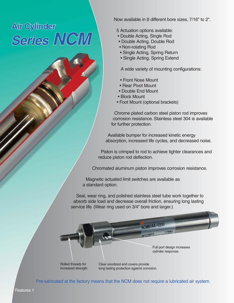
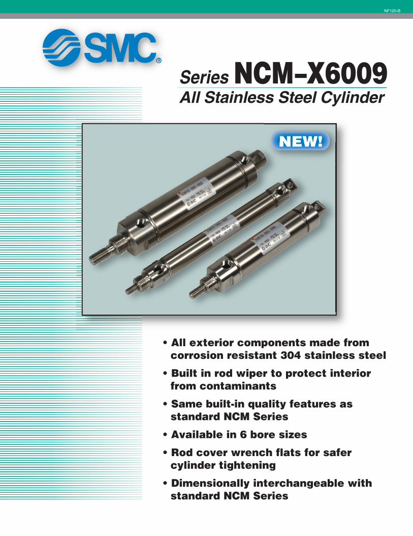
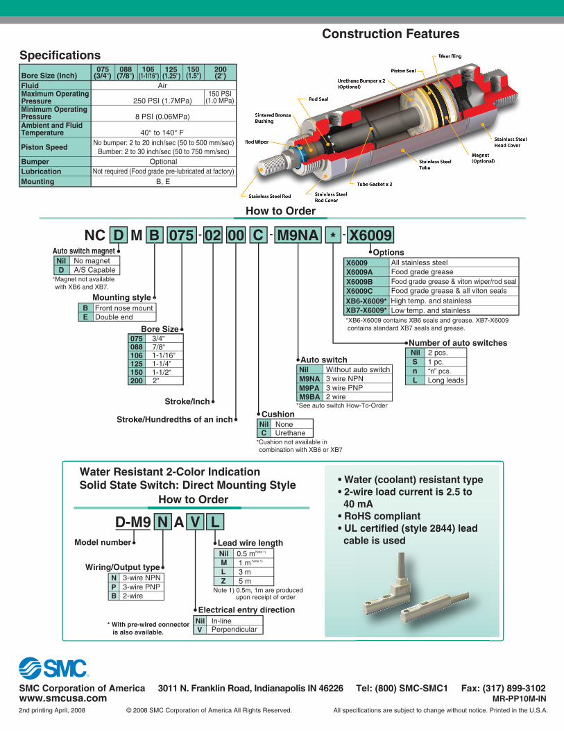
Now available in 8 different bore sizes, 7/16" to 2".
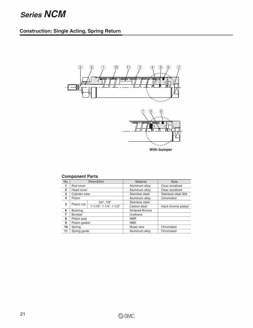
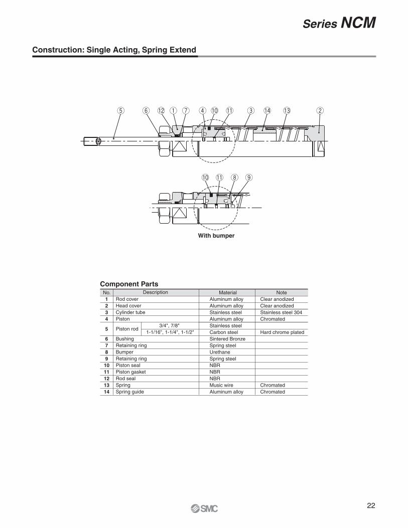
5 Actuation options available:• Double Acting, Single Rod• Double Acting, Double Rod• Non-rotating Rod• Single Acting, Spring Return• Single Acting, Spring Extend
A wide variety of mounting configurations:
• Front Nose Mount• Rear Pivot Mount• Double End Mount• Block Mount• Foot Mount (optional brackets)
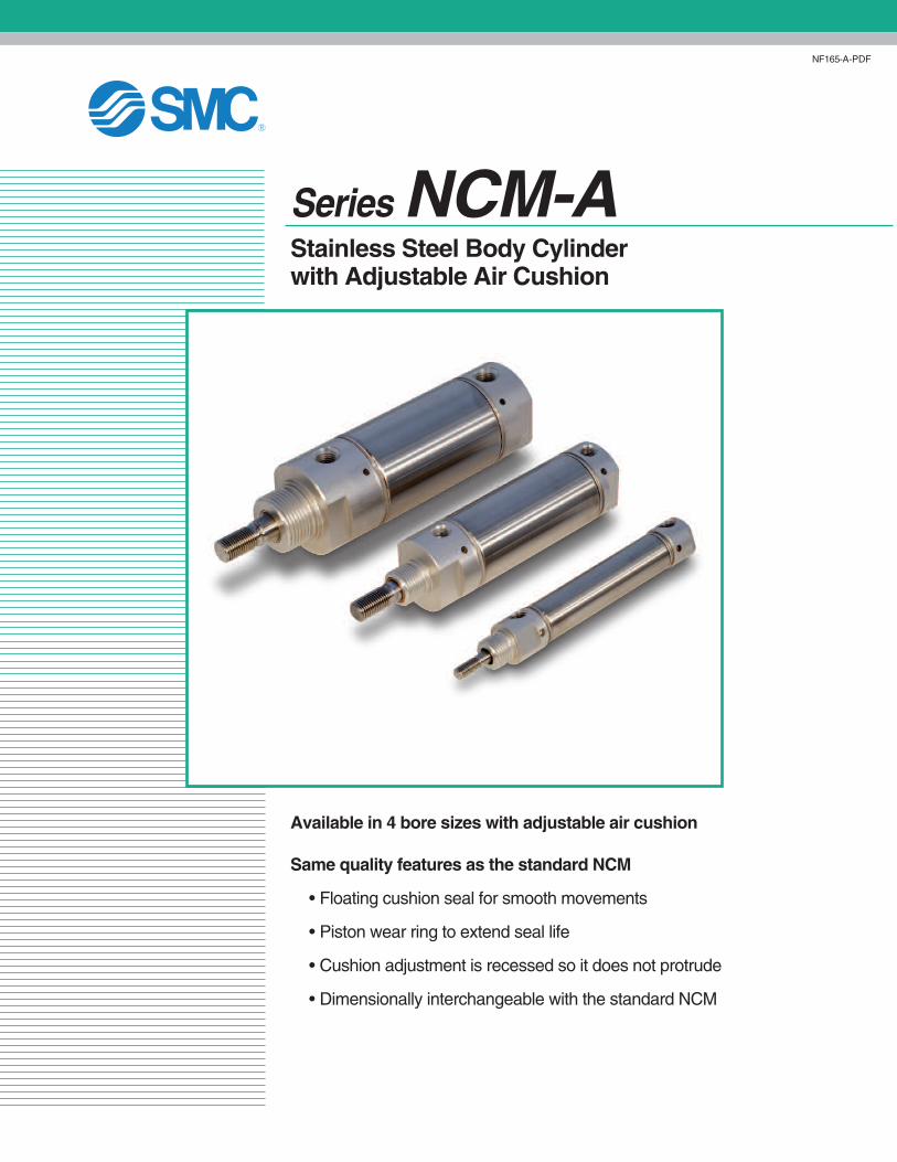
Chrome plated carbon steel piston rod improves corrosion resistance. Stainless steel 304 is available
for further protection.
Available bumper for increased kinetic energy absorption, increased life cycles, and decreased noise.
Piston is crimped to rod to achieve tighter clearances and reduce piston rod deflection.
Take the impact at the stroke end into consideration.
The aspects indicated below may need to be taken into consideration, depending on how the cylinder is operated.
Obtain the cylinder’s air consumption and its required air volume.
1
Step
2
Step
Step
3
4
Note)
Note) If it is particularly necessary to operate at high speeds, the load rate must be reduced further. (In the graph, it is possible to select a load rate of 0.4, 0.3, 0.2 or less.)
Note) If the same load is applied both for pushing and pulling in a horizontal operation, set the direction to the pulling side.
Determine the operating pressure.
Generally, set the regulator to 85% of the source air pressure. (In the graph, a selection between 0.2 MPa and 0.8 MPa is possible.)
Determine the direction in which the cylinder force will be used.
Extending side � Refer to Graph (1).
Retracting side � Refer to Graph (2).
When an external stopper (shock absorber, etc.) is provided to
absorb the impact, select a stopper with sufficient absorption
capacity.
Stopping the piston with the cylinder without a stopper:
Verify in Graph (3) to (4) the absorption capacity of the cushion that is enclosed in the cylinder.
Bumper ··················· Urethane rubber is used for preventing metal-to-metal contact between the piston and the cover.
If a lateral load is applied to the piston rod:
Verify in Graph (5) whether the lateral load is within an allowable range.
When using a cylinder with a relatively long stroke, if a buckling
force acts on the piston rod or the cylinder tube, verify in the
table whether the stroke or the operating pressure is within a
safe range.
Obtain the air consumption selecting a compressor and for calculating
the running cost and the required (Graph (6) to (7)) that is necessary for
selecting a compressor and for calculating the running cost and the
required air volume (Graph (8)) that is necessary for selecting
equipment such as an air filter or a regulator, or the size of the piping
upstream.
Front matter 2
Model Selection
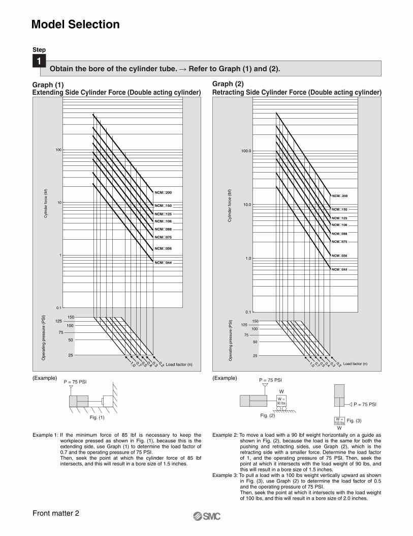
Obtain the bore of the cylinder tube. � Refer to Graph (1) and (2).
P = 75 PSI
W
Fig. (2)
W =90 lbs P = 75 PSI
Fig. (3)
W
W =100 lbs
Fig. (1)
P = 75 PSI(Example) (Example)
Graph (2)
Retracting Side Cylinder Force (Double acting cylinder)Graph (1)Extending Side Cylinder Force (Double acting cylinder)
Example 1: If the minimum force of 85 lbf is necessary to keep the workpiece pressed as shown in Fig. (1), because this is the extending side, use Graph (1) to determine the load factor of 0.7 and the operating pressure of 75 PSI. Then, seek the point at which the cylinder force of 85 lbf intersects, and this will result in a bore size of 1.5 inches.
Example 2: To move a load with a 90 lbf weight horizontally on a guide as shown in Fig. (2), because the load is the same for both the pushing and retracting sides, use Graph (2), which is the retracting side with a smaller force. Determine the load factor of 1, and the operating pressure of 75 PSI. Then, seek the point at which it intersects with the load weight of 90 lbs, and this will result in a bore size of 1.5 inches.
Example 3: To pull a load with a 100 lbs weight vertically upward as shown in Fig. (3), use Graph (2) to determine the load factor of 0.5 and the operating pressure of 75 PSI. Then, seek the point at which it intersects with the load weight of 100 lbs, and this will result in a bore size of 2.0 inches.
Step
1
0.1
1
10
100
Cyl
inde
r fo
rce
(lbf)
NCM�044
25
150125
100
75
50
Ope
ratin
g pr
essu
re (
PS
I)
NCM�075
NCM�088
NCM�106
NCM�125
NCM�150
NCM�200
1.00.7
0.50.4
0.30.2
NCM�056
0.1
1.0
10.0
100.0
Cyl
inde
r fo
rce
(lbf)
25
150125
100
75
50
Ope
ratin
g pr
essu
re (
PS
I)
NCM�075
NCM�088
NCM�106
NCM�125
NCM�150
NCM�200
1.00.7
0.50.4
0.30.2
NCM�056
NCM�044
Load factor (n) Load factor (n)
Front matter 3
Model Selection
With Bumper Without Bumper
Step
2Take the impact at the stroke end into consideration.
NCM
Graph (4)
Allowable Kinetic Energy without Bumper
0.01
0.10
1.00
10.00
100.00
1000.00
1 10 100
Max. speed (in/s)
Load
(lb
)
NCM�075
NCM�088
NCM�106
NCM�125
NCM�150
NCM�200
NCM�056
NCM�044
Graph (3)
Allowable Kinetic Energy with Bumper
0.01
0.10
1.00
10.00
100.00
1000.00
1 10 100
Max. speed (in/s)
Load
(lb
)
NCM�075
NCM�088
NCM�106
NCM�125
NCM�150
NCM�200
NCM�056
NCM�044
Front matter 4
Model Selection
The maximum stroke at which the cylinder can be operated under a lateral load.The region that does not exceed the bold solid line represents the allowable lateral load in relation to the cylinder of a given stroke length. In the graph, the range of the broken line shows that the long stroke limit has been exceeded. In this region, as a rule, operate the cylinder by providing a guide along the direction of movement.
The aspects indicated below may need to be taken into consideration, depending on how the cylinder is operated.
Step
3
0.01
0.10
1.00
10.00
100.00
0 10 20 30 405 15 25 35 45
Cylinder stroke (in)
Late
ral l
oad
appl
ied
to th
e ro
d en
d fR
(lb
f) NCME�NCMC�
NCMB�
NCM�044
NCM�056
NCM�200
NCM�150
NCM�125
NCM�106
NCM�088NCM�075
Front matter 5
Model Selection
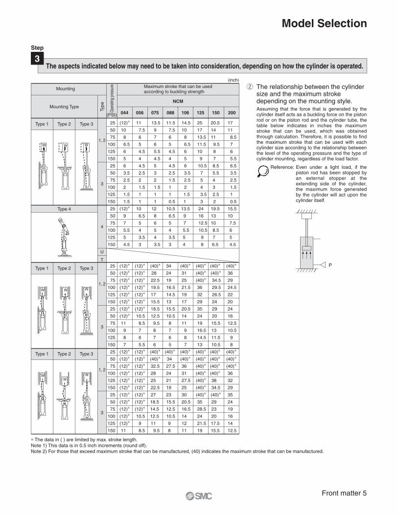
∗ The data in ( ) are limited by max. stroke length.Note 1) This data is in 0.5 inch increments (round off).Note 2) For those that exceed maximum stroke that can be manufactured, (40) indicates the maximum stroke that can be manufactured.
Assuming that the force that is generated by the cylinder itself acts as a buckling force on the piston rod or on the piston rod and the cylinder tube, the table below indicates in inches the maximum stroke that can be used, which was obtained through calculation. Therefore, it is possible to find the maximum stroke that can be used with each cylinder size according to the relationship between the level of the operating pressure and the type of cylinder mounting, regardless of the load factor.
P
The relationship between the cylinder size and the maximum stroke depending on the mounting style.
Reference: Even under a light load, if the piston rod has been stopped by an external stopper at the extending side of the cylinder, the maximum force generated by the cylinder will act upon the cylinder itself.
The aspects indicated below may need to be taken into consideration, depending on how the cylinder is operated.
Step
3
Mounting Maximum stroke that can be used according to buckling strength
NCM
Mounting TypeTy
pe
Oper
ating
pre
ssur
e
Type 1 Type 2 Type 3
Type 2 Type 3
Type 2 Type 3
Type 1
Type 1
Type 4
(inch)
W W W
WW W
W
WW
W
(PSI)
17
11
8.5
7
6
5.5
6.5
3.5
2.5
1.5
1
0.5
15.5
10
7.5
6
5
4.5
(40)∗
36
29
24.5
22
20
24
16
12.5
10.5
9
8
(40)∗
(40)∗
(40)∗
36
32
29
35
24
19
16
14
12.5
200
1, 2
3
4
U
T
1, 2
3
1, 2
3
25
50
75
100
125
150
25
50
75
100
125
150
25
50
75
100
125
150
25
50
75
100
125
150
25
50
75
100
125
150
25
50
75
100
125
150
25
50
75
100
125
150
075
13.5
9
7
6
5.5
4.5
5
3
2
1.5
1
1
12
8
6
5
4
3.5
(40)∗
28
22.5
19.5
17
15.5
18.5
12.5
9.5
8
7
6
(40)∗
(40)∗
32.5
28
25
22.5
27
18.5
14.5
12.5
11
9.5
088
11.5
7.5
6
5
4.5
4
4.5
2.5
1.5
1
1
0.5
10.5
6.5
5
4
3.5
3
34
24
19
16.5
14.5
13
15.5
10.5
8
7
6
5
(40)∗
34
27.5
24
21
19
23
15.5
12.5
10.5
9
8
106
14.5
10
8
6.5
6
5
6
3.5
2.5
2
1.5
1
13.5
9
7
5.5
5
4
(40)∗
31
25
21.5
19
17
20.5
14
11
9
8
7
(40)∗
(40)∗
36
31
27.5
25
30
20.5
16.5
14
12
11
125
25
17
13.5
11.5
10
9
10.5
7
5
4
3.5
3
24
16
12.5
10.5
9
8
(40)∗
(40)∗
(40)∗
36
32
29
35
24
19
16.5
14.5
13
(40)∗
(40)∗
(40)∗
(40)∗
(40)∗
(40)∗
(40)∗
35
28.5
24
21.5
19
150
20.5
14
11
9.5
8
7
8.5
5.5
4
3
2.5
2
19.5
13
10
8.5
7
6.5
(40)∗
(40)∗
34.5
29.5
26.5
24
29
20
15.5
13
11.5
10.5
(40)∗
(40)∗
(40)∗
(40)∗
38
34.5
(40)∗
29
23
20
17.5
15.5
056
11
7.5
6
5
4.5
4
4.5
2.5
2
1.5
1
1
10
6.5
5
4
3.5
3
(12)∗
(12)∗
(12)∗
(12)∗
(12)∗
(12)∗
(12)∗
10.5
8.5
7
6
5.5
(12)∗
(12)∗
(12)∗
(12)∗
(12)∗
(12)∗
(12)∗
(12)∗
(12)∗
10.5
9
8.5
044
(12)∗
10
8
6.5
6
5
6
3.5
2.5
2
1.5
1.5
(12)∗
9
7
5.5
5
4.5
(12)∗
(12)∗
(12)∗
(12)∗
(12)∗
(12)∗
(12)∗
(12)∗
11
9
8
7
(12)∗
(12)∗
(12)∗
(12)∗
(12)∗
(12)∗
(12)∗
(12)∗
(12)∗
(12)∗
(12)∗
11
Front matter 6
Model Selection
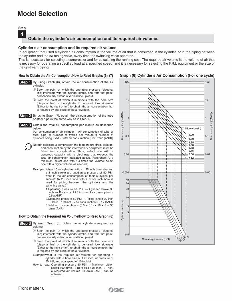
How to Obtain the Air Consumption/How to Read Graphs (6), (7)
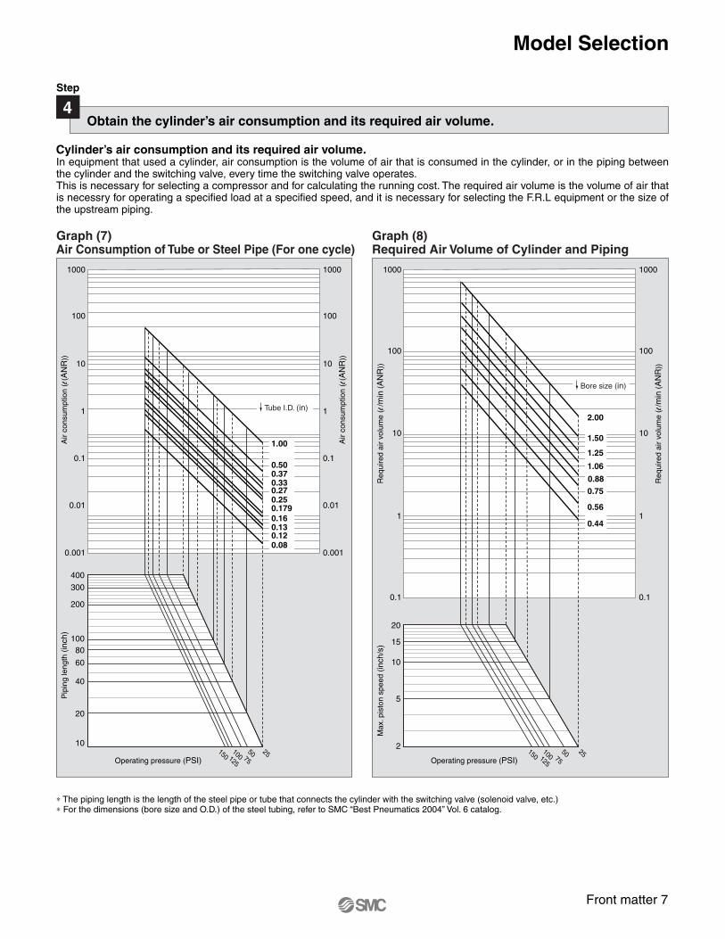
How to Obtain the Required Air Volume/How to Read Graph (8)
In equipment that used a cylinder, air consumption is the volume of air that is consumed in the cylinder, or in the piping between the cylinder and the switching valve, every time the switching valve operates.This is necessary for selecting a compressor and for calculating the running cost. The required air volume is the volume of air that is necessry for operating a specified load at a specified speed, and it is necessary for selecting the F.R.L equipment or the size of the upstream piping.
Note)In selecting a compressor, the temperature drop, leakage, and consumption by the intermediary equipment must be taken into consideration. Thus, select one with a generous capacity, with a discharge that exceeds the total air consumption indicated above. (Reference: At a minimum, select one with 1.4 times the volume; select one with a higher volume as needed.)
1.Operating pressure 50 PSI � Cylinder stroke 30 inch � Bore size 1.25 inch � Air consumption ≅ 0.5 l(ANR)
2.Operating pressure 50 PSI � Piping length 20 inch � Bore 0.179 inch � Air consumption ≅ 0.1 l (ANR)
3.Total air consumption = (0.5 + 0.1) x 10 x 5 = 30 l/min (ANR)
Example: When 10 air cylinders with a 1.25 inch bore size and a 3 inch stroke are used at a pressure of 50 PSI, what is the air consumption of their 5 cycles per minute? (A 20 inch tube with a 0.179 inch bore is used for piping between the cylinders and the switching valve.)
Obtain the cylinder’s air consumption and its required air volume.
Cylinder’s air consumption and its required air volume.
Step 1
Step 2
Step 3
Step 3
Graph (6) Cylinder’s Air Consumption (For one cycle)
Air
cons
umpt
ion
(l (
AN
R))
Cyl
inde
r st
roke
(in
)
Air
cons
umpt
ion
(l(A
NR
))
Operating pressure (PSI)
By using Graph (6), obtain the air consumption of the air cylinder.
Seek the point at which the operating pressure (diagonal line) intersects with the cylinder stroke, and from that point, perpendicularly extend a vertical line upward.From the point at which it intersects with the bore size (diagonal line) of the cylinder to be used, look sideways (Either to the right or left) to obtain the air consumption that is required by one cycle of the air cylinder.
By using Graph (7), obtain the air consumption of the tube or steel pipe in the same way as in Step 1.
Obtain the total air consumption per minute as described below.(Air consumption of air cylinder + Air consumption of tube or steel pipe) x Number of cycles per minute x Number of cylinders being used = Total air consumption [Unit: l/min (ANR)]
By using Graph (8), obtain the air cylinder’s required air volume.
Seek the point at which the operating pressure (diagonal line) intersects with the cylinder stroke, and from that point, perpendicularly extend a vertical line upward.From the point at which it intersects with the bore size (diagonal line) of the cylinder to be used, look sideways (Either to the right or left) to obtain the air consumption that is required by one cycle of the air cylinder.
Example:What is the required air volume for operating a cylinder with a bore size of 1.25 inch, at pressure of 50 PSI, and at a speed of 10 inch/s?
How to read: Operating pressure 50 PSI � Maximum piston speed 500 mm/s � Bore size 1.25 inch � Then, a required air volume 30 l/min (ANR) can be obtained.
Step
4
100
10
1
0.1
0.01
0.001
100
10
1
0.1
0.01
0.001
4030
20
10
5
3
0.5
1
2575125
50100150
Bore size (in)
2.00
1.50
1.251.060.880.75
0.56
0.44
Front matter 7
Graph (7) Air Consumption of Tube or Steel Pipe (For one cycle)
Graph (8) Required Air Volume of Cylinder and Piping
∗ The piping length is the length of the steel pipe or tube that connects the cylinder with the switching valve (solenoid valve, etc.)∗ For the dimensions (bore size and O.D.) of the steel tubing, refer to SMC “Best Pneumatics 2004” Vol. 6 catalog.
Obtain the cylinder’s air consumption and its required air volume.
Step
4
In equipment that used a cylinder, air consumption is the volume of air that is consumed in the cylinder, or in the piping between the cylinder and the switching valve, every time the switching valve operates.This is necessary for selecting a compressor and for calculating the running cost. The required air volume is the volume of air that is necessry for operating a specified load at a specified speed, and it is necessary for selecting the F.R.L equipment or the size of the upstream piping.
Cylinder’s air consumption and its required air volume.
Req
uire
d ai
r vo
lum
e (l
/min
(A
NR
))M
ax. p
isto
n sp
eed
(inch
/s)
Req
uire
d ai
r vo
lum
e (l
/min
(A
NR
))
Operating pressure (PSI)
1000
100
10
1
0.1
1000
100
10
1
0.1
20
15
10
2
5
2575125
50100150
Bore size (in)
2.00
1.50
1.25
1.06
0.88
0.75
0.56
0.44
Air
cons
umpt
ion
(l(A
NR
))P
ipin
g le
ngth
(in
ch)
Air
cons
umpt
ion
(l(A
NR
))
100
400
300
200
80
60
40
20
10
Operating pressure (PSI)25
75125
50100150
1.00
0.500.370.330.270.250.179
0.160.130.12
0.08
Tube I.D. (in)
10001000
100100
1010
11
0.10.1
0.010.01
0.0010.001
Model Selection
1
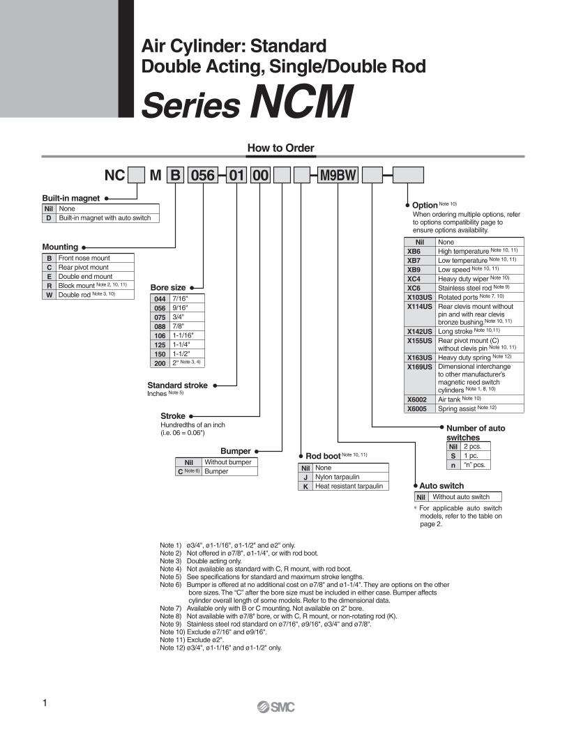
Air Cylinder: StandardDouble Acting, Single/Double Rod
Front nose mountRear pivot mountDouble end mountBlock mount Note 2, 10, 11)
Double rod Note 3, 10)
When ordering multiple options, refer to options compatibility page to ensure options availability.
Standard stroke
Number of auto switches
Nil
J
K
Note 1) ø3/4", ø1-1/16", ø1-1/2" and ø2" only.Note 2) Not offered in ø7/8", ø1-1/4", or with rod boot.Note 3) Double acting only.Note 4) Not available as standard with C, R mount, with rod boot.Note 5) See specifications for standard and maximum stroke lengths.Note 6) Bumper is offered at no additional cost on ø7/8" and ø1-1/4". They are options on the other
bore sizes. The “C” after the bore size must be included in either case. Bumper affects cylinder overall length of some models. Refer to the dimensional data.
Note 7) Available only with B or C mounting. Not available on 2" bore.Note 8) Not available with ø7/8" bore, or with C, R mount, or non-rotating rod (K).Note 9) Stainless steel rod standard on ø7/16", ø9/16", ø3/4" and ø7/8".Note 10) Exclude ø7/16" and ø9/16".Note 11) Exclude ø2".Note 12) ø3/4", ø1-1/16" and ø1-1/2" only.
Option Note 10)
Hundredths of an inch (i.e. 06 = 0.06")
Nil
XB6
XB7
XB9
XC4
XC6
X103US
X114US
None High temperature Note 10, 11)
Low temperature Note 10, 11)
Low speed Note 10, 11)
Heavy duty wiper Note 10)
Stainless steel rod Note 9)
Rotated ports Note 7, 10)
Rear clevis mount withoutpin and with rear clevisbronze bushing.Note 10, 11)
X142US
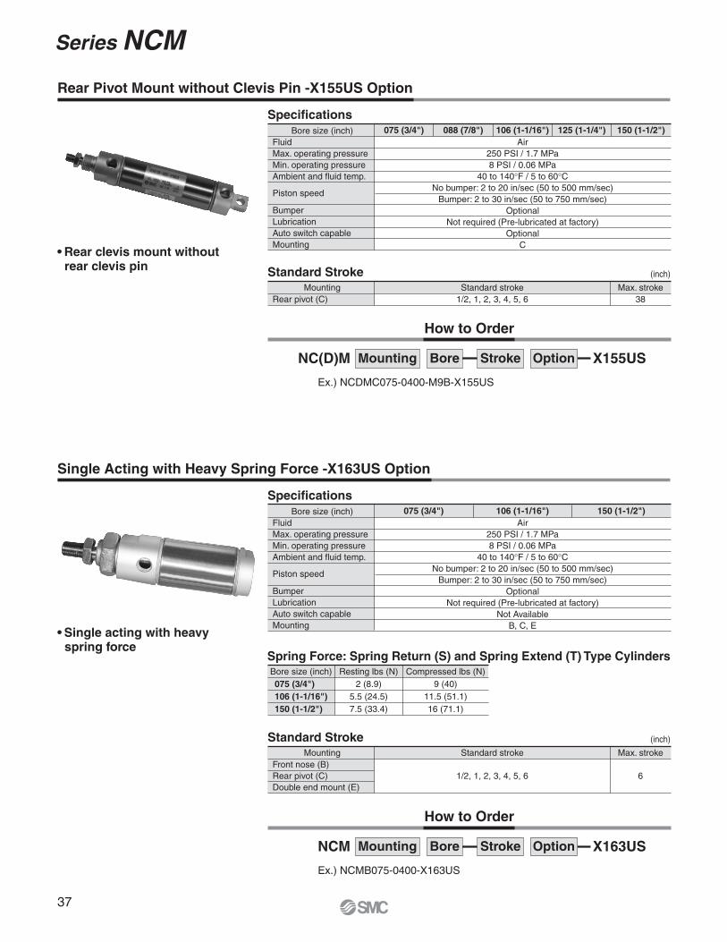
X155US
Long stroke Note 10,11)
Rear pivot mount (C)without clevis pin Note 10, 11)
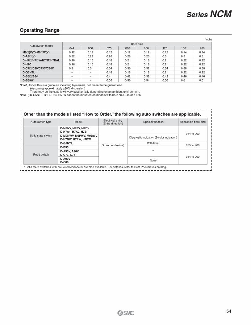
∗ For applicable auto switch models, refer to the table on page 2.
2
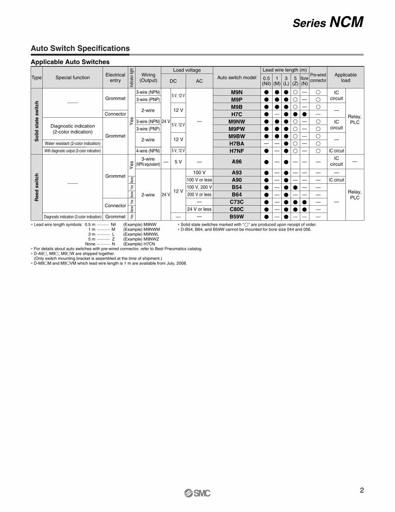
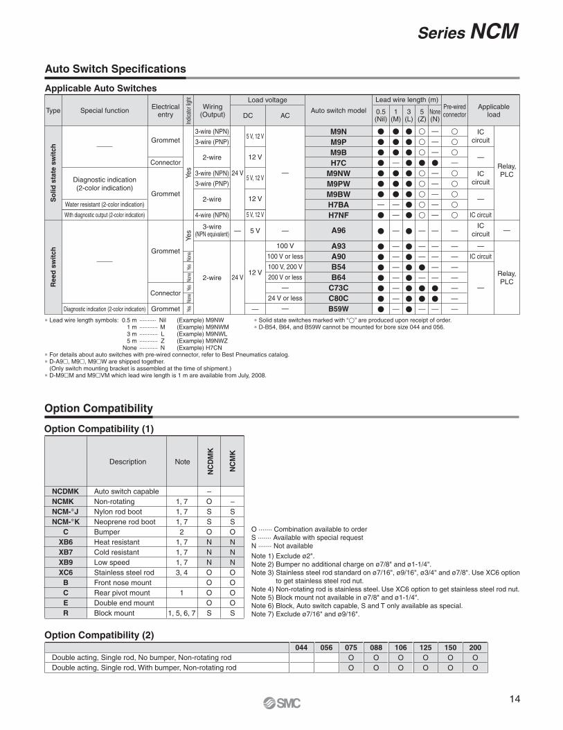
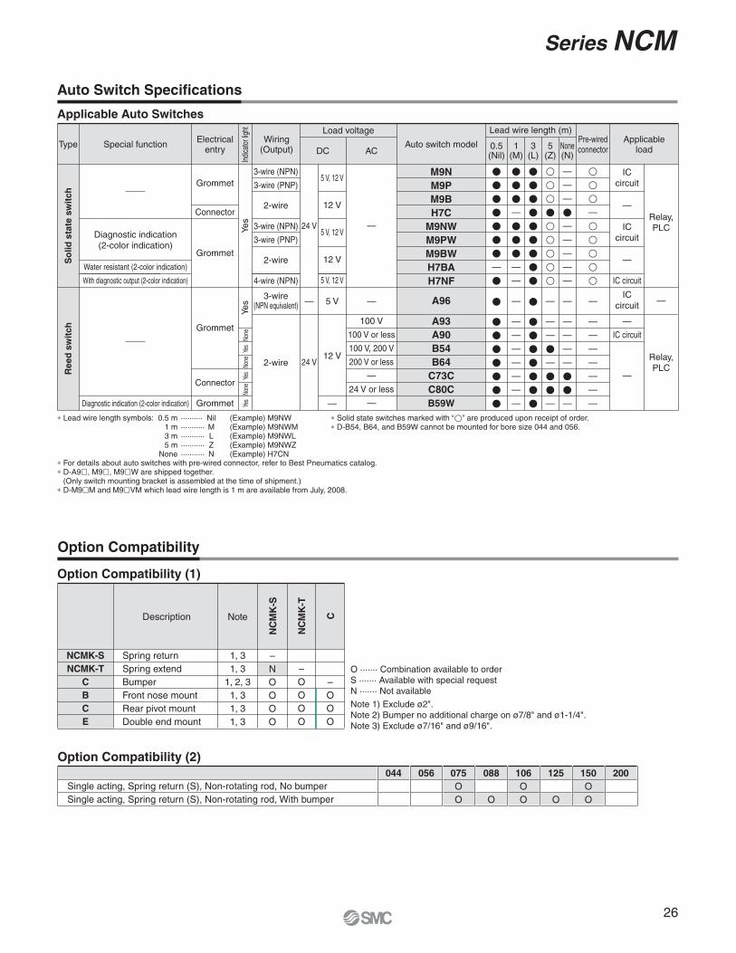
Auto Switch Specifications
Series NCM
Applicable Auto Switches
∗ Lead wire length symbols: 0.5 m ·········· Nil (Example) M9NW1 m ··········· M (Example) M9NWM3 m ··········· L (Example) M9NWL5 m ··········· Z (Example) M9NWZ
None ··········· N (Example) H7CN
∗ Solid state switches marked with “�” are produced upon receipt of order.∗ D-B54, B64, and B59W cannot be mounted for bore size 044 and 056.
∗ For details about auto switches with pre-wired connector, refer to Best Pneumatics catalog.∗ D-A9�, M9�, M9�W are shipped together.
(Only switch mounting bracket is assembled at the time of shipment.)∗ D-M9�M and M9�VM which lead wire length is 1 m are available from July, 2008.
Type Special function Electricalentry
Grommet
Connector
Grommet
Wiring(Output)
3-wire (NPN)
3-wire (PNP)
2-wire
3-wire (NPN)
3-wire (PNP)
2-wire
4-wire (NPN)
Load voltage
DC
24 V
5 V, 12 V
12 V
5 V, 12 V
12 V
5 V, 12 V
AC
Lead wire length (m)
0.5(Nil)
�������—
�
�
�������
3(L)
���������
�
�������
1(M)
���—
���—
—
—
—
—
—
—
—
—
—
5(Z)
���������
—
—
—
�—
��—
None(N)
—
—
—
�—
—
—
—
—
—
—
—
—
—
��—
���—
�����
—
—
—
—
—
—
—
—
Applicableload
Pre-wiredconnector
IC circuit
—
—
ICcircuit
ICcircuit
Relay,PLC
Auto switch model
Diagnostic indication(2-color indication)
M9N
M9P
M9B
H7C
M9NW
M9PW
M9BW
H7BA
H7NF
A96
A93
A90
B54
B64
C73C
C80C
B59W
—
So
lid
sta
te s
wit
ch
Indic
ator
light
Yes
Water resistant (2-color indication)
With diagnostic output (2-color indication)
Grommet
Grommet
Connector
100 V
100 V or less
100 V, 200 V
200 V or less
—
24 V or less
—
3-wire(NPN equivalent)
2-wire 24 V
5 V
12 V
—
ICcircuit
IC circuit
—
—
Relay,PLC
Diagnostic indication (2-color indication)
———
Re
ed
sw
itch
Yes
None
Yes
None
Yes
None
Yes
3
Series NCM
Option Compatibility
Option Compatibility (2)
Double acting, Single rod, No bumperDouble acting, Single rod, With bumperDouble acting, Double rod, No bumperDouble acting, Double rod, With bumperWith rod bootDirect double acting, Single rod, No bumperDirect double acting, Single rod, With bumperDirect single acting, Spring return (S), No bumperDirect single acting, Spring extend (T), No bumperDouble acting, Single rod, No bumper XB6Double acting, Single rod, No bumper XB7Double acting, Single rod, No bumper XB9Double acting, Single rod, With bumper XB9Double acting, Single rod, No bumper XC6Double acting, Single rod, With bumper XC6Double acting, Single rod, No bumper, With air cushion
044
OO
Standard
Standard
056
OO
Standard
Standard
075
OOOOOOOOOOOOOOOO
088
OOOOO
OOOOOOO
106
OOOOOOOOOOOOOOOO
125
OOOOO
OOOO
OO
150
OOOOOOOOOOOOOOOO
200
OO
Option Compatibility (1)
NCM
NCDM
NCMW
NCM-∗J
NCM-∗K
C
XB6
XB7
XB9
XC6
B
C
E
R
StandardAuto switch capableDouble rodNylon rod bootNeoprene rod bootBumperHeat resistantCold resistantLow speedStainless steel rodFront nose mountRear pivot mountDouble end mountBlock mount
51, 51, 52
1, 51, 51, 53 1
1, 5
–OOOOOOOOOOOOO
–OOOOSSSOOOOOO
–SSOOOSONNNS
–NOSSSOOOON
–OSSSOOOON
–NNOOOOOO
–NNOOOOS
–NOOOOS
–OOOOO
–OOOO
O ······· Combination available to orderS ······· Available with special requestN ······· Not available
Note 1) Exclude ø2".Note 2) Bumper no additional charge on ø7/8" and ø1-1/4".Note 3) Stainless steel rod standard on ø7/16", ø9/16", ø3/4" and ø7/8". Use XC6 option to get stainless steel rod nut.Note 4) Block mount not available in ø7/8" and ø1-1/4".Note 5) Exclude ø7/16" and ø9/16".
Description
NC
M–S
tan
dard
NC
DM
NC
MW
NC
M-∗
J
NC
M-∗
K
C
XB
6
XB
7
XB
9
XC
6
Note
4
Series NCM
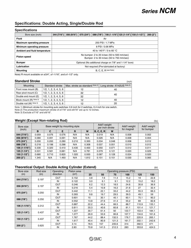
Specifications: Double Acting, Single/Double Rod
Fluid
Maximum operating pressure
Minimum operating pressure
Ambient and fluid temperature
Piston speed
Bumper
Lubrication
Mounting
Air
250 PSI / 1.7 MPa
8 PSI / 0.06 MPa
40 to 140°F / 5 to 60 °C
No bumper: 2 to 20 in/sec (50 to 500 mm/sec) Bumper: 2 to 30 in/sec (50 to 750 mm/sec)
Optional (No additional charge on 7/8" and 1-1/4" bore)
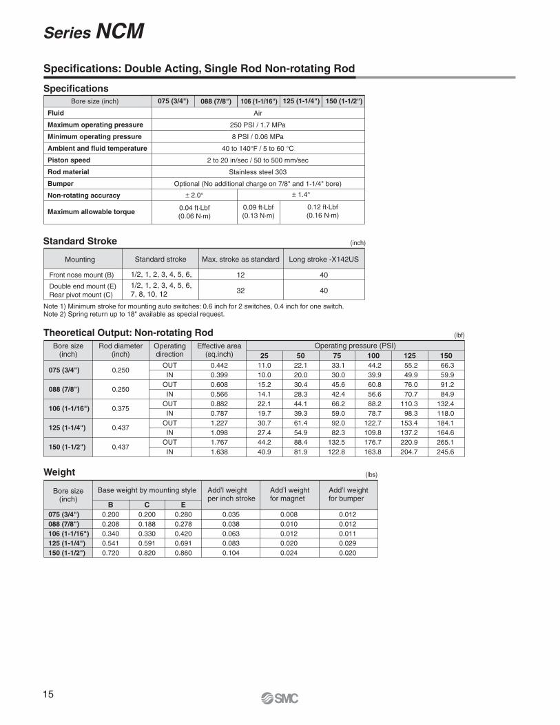
Note 1) Minimum stroke for mounting auto switches: 0.6 inch for 2 switches, 0.4 inch for one switch.Note 2) The production maximum stroke of ø7/16" and ø9/16" are up to 12 inches.Note 3) Exclude ø7/16" and ø9/16".
(inch)
Max. stroke as standard Note 2)
(lbs)Weight (Except Non-rotating Rod)
Bore size(inch)
Base weight by mounting styleAdd’l weightper inch stroke Add’l weight
t2-Drill & C'Bore for NH caps screw & NT UNC from bottom
EE NPTEE NPT
øE
NE
TN
CAEA
EA
Block Mount
11
Series NCM
Bore size (inch)075 (3/4")
088 (7/8")
106 (1-1/16")
125 (1-1/4")
150 (1-1/2")
200 (2")
MM
0.2500.2500.3120.4370.4370.625
A
0.500.500.500.750.750.88
E
0.860.931.121.321.562.06
K
––
0.120.250.250.38
N
0.750.750.881.061.251.75
W
0.500.500.620.880.881.19
Y
0.950.951.171.621.501.91
YE
0.450.450.550.740.620.72
ZC
0.090.090.090.090.090.12
ZD
1/8 NPT1/8 NPT1/8 NPT1/8 NPT1/8 NPT1/4 NPT
D
––
0.250.380.380.50
B
0.6240.6240.6240.7490.7491.375
KK
1/4-281/4-285/16-247/16-207/16-201/2-20
NN
5/8-185/8-185/8-183/4-163/4-16
1-1/4-12
0–0.0030
–0.0030
–0.0030
–0.0030
–0.0030
–0.003
(inch)
Bore size (inch)
075 (3/4")
088 (7/8")
106 (1-1/16")
125 (1-1/4")
150 (1-1/2")
200 (2")
No bumper
3.002.662.753.563.384.18
With bumper
3.002.912.883.813.514.44
Double Acting, Double Rod
Note) Length not affected by addition of magnet except 106 bore.
LB
No bumper
4.003.664.005.315.126.56
With bumper
4.003.914.135.565.256.82
ZB
Bore size (inch)
106 (1-1/16")
No bumper
3.13With bumper
3.25
Double Acting, Double Rod with Magnet (106 Bore)
LB
No bumper
4.38With bumper
4.50
ZB
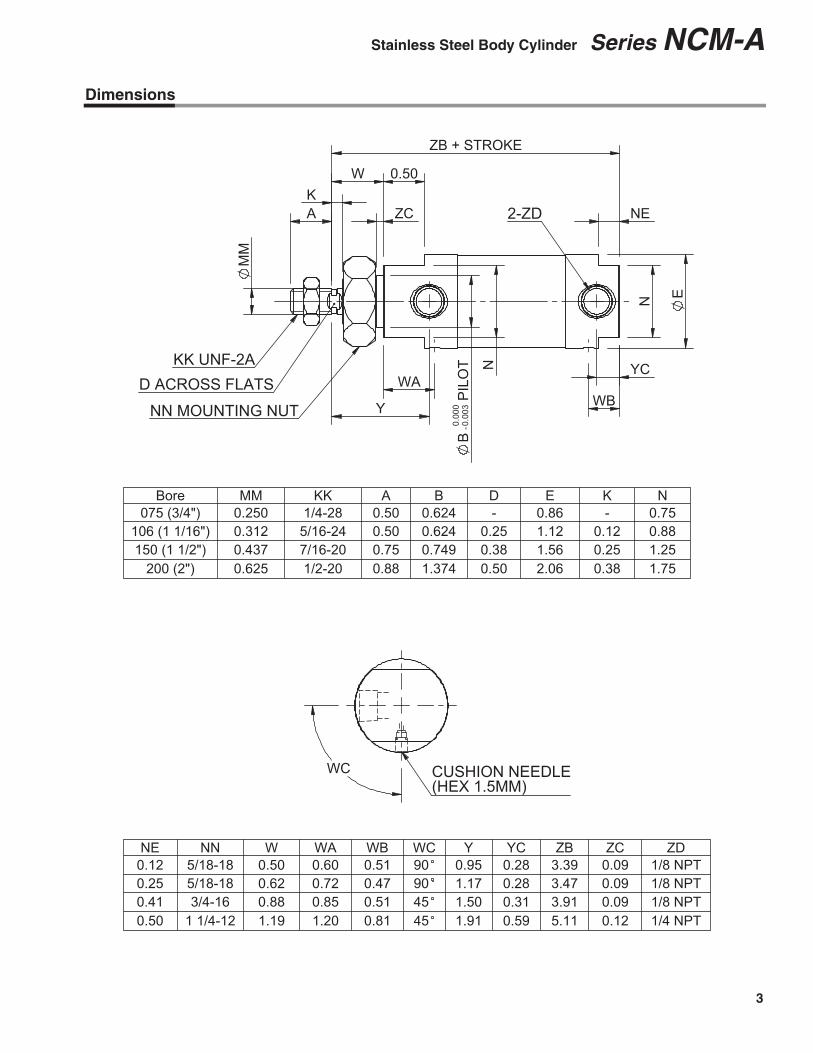
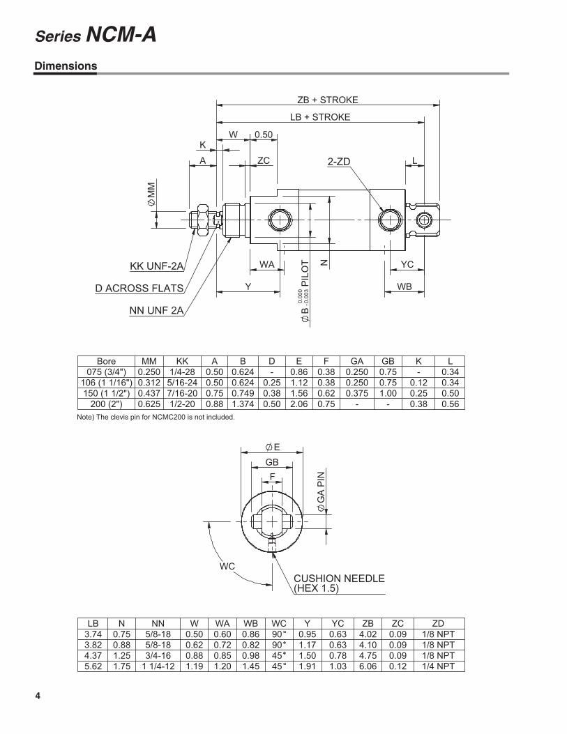
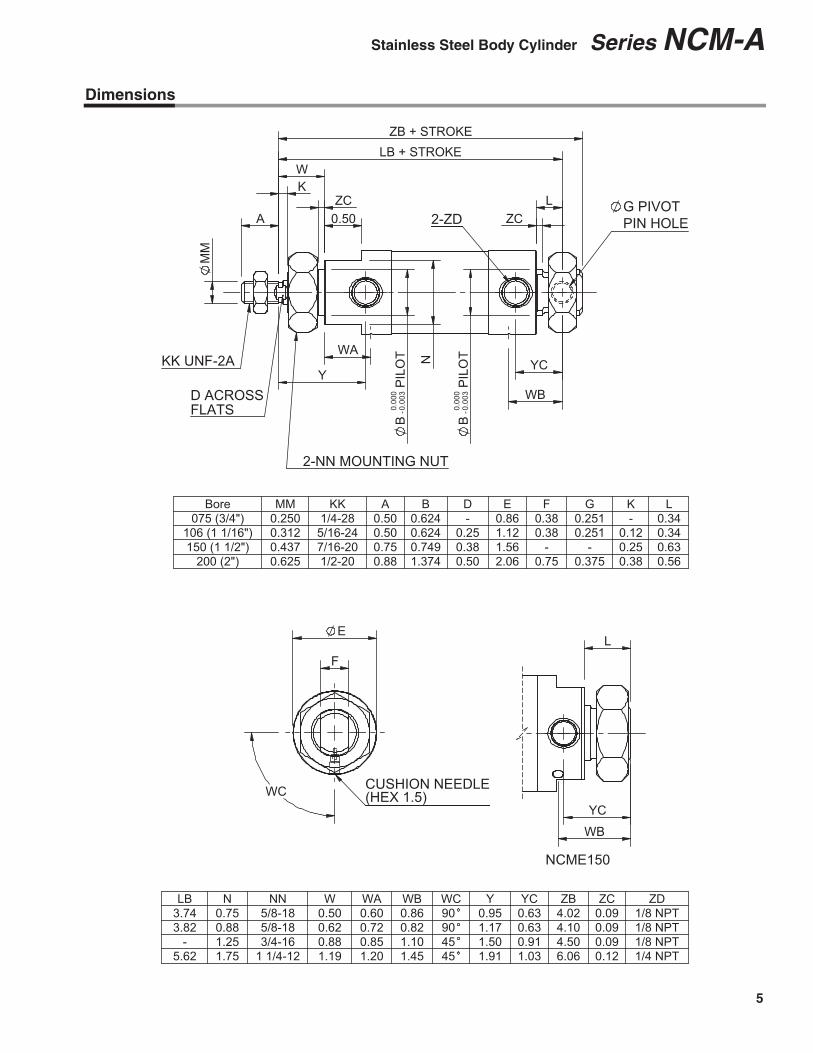
Dimensions: Double Acting, Double Rod
2-NN Mounting Nut(incl. except 2" bore)
ZB + (2 X Stroke)
LB + Stroke W + StrokeW
YEK
AøE
øM
M
2-KK UNF-2A
2-D Across Flats
2-Y
0.50 2-ZD 2-ZC0.50
YE
A
2-ø
B P
ilot
2-N
13
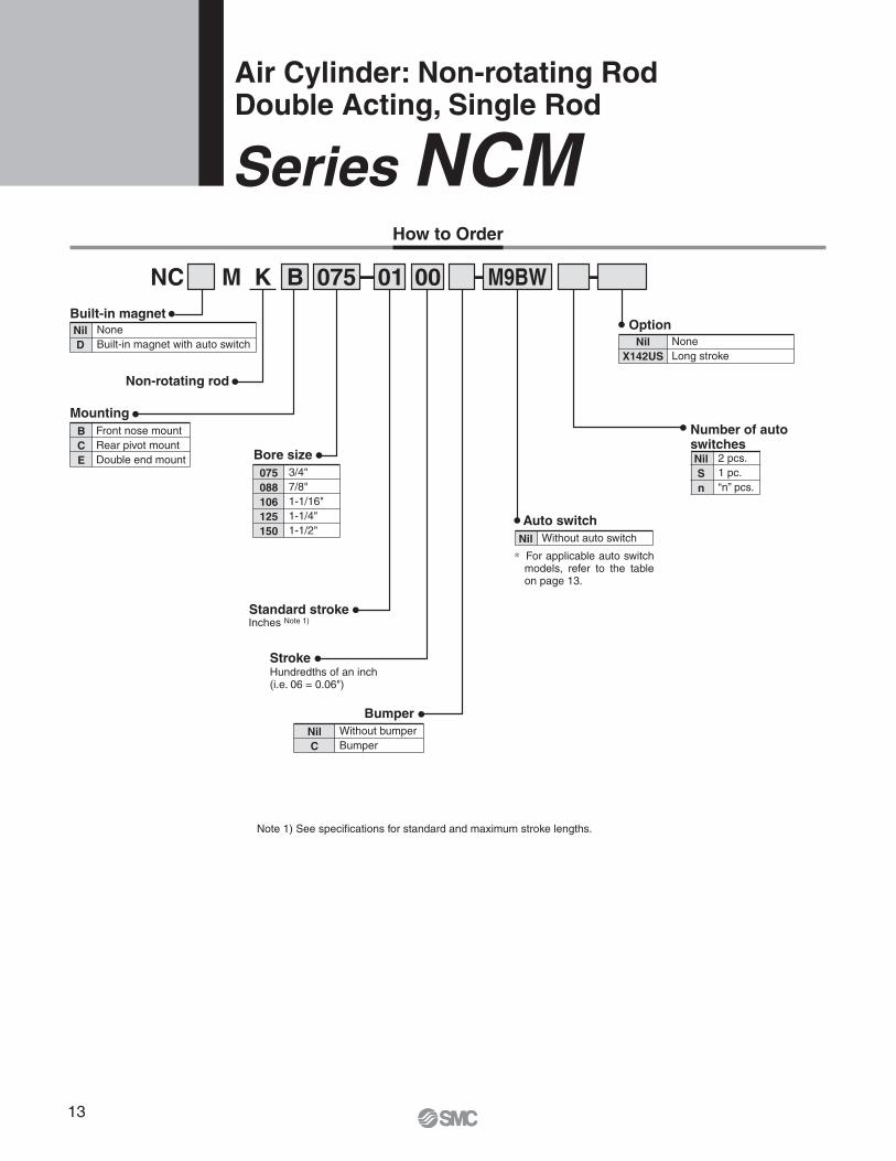
Air Cylinder: Non-rotating RodDouble Acting, Single Rod
Series NCM
Bore size
Inches Note 1)
Stroke
- - -
How to Order
B 075 01 00 M9BW
Nil
C
Without bumperBumper
Bumper
Nil Without auto switch
Auto switch
Nil
S
n
2 pcs.1 pc.“n” pcs.
075
088
106
125
150
3/4"7/8"1-1/16"1-1/4"1-1/2"
Standard stroke
Number of auto switches
Note 1) See specifications for standard and maximum stroke lengths.
Option
Hundredths of an inch (i.e. 06 = 0.06")
Nil
X142US
NoneLong stroke
Mounting
Nil
D
NoneBuilt-in magnet with auto switch
Non-rotating rod
NC M
Built-in magnet
B
C
E
Front nose mountRear pivot mountDouble end mount
K
∗ For applicable auto switch models, refer to the table on page 13.
14
Series NCM
Auto Switch Specifications
Applicable Auto Switches
∗ Lead wire length symbols: 0.5 m ·········· Nil (Example) M9NW 1 m ··········· M (Example) M9NWM 3 m ··········· L (Example) M9NWL 5 m ··········· Z (Example) M9NWZ None ··········· N (Example) H7CN
∗ Solid state switches marked with “�” are produced upon receipt of order.∗ D-B54, B64, and B59W cannot be mounted for bore size 044 and 056.
∗ For details about auto switches with pre-wired connector, refer to Best Pneumatics catalog.∗ D-A9�, M9�, M9�W are shipped together.
(Only switch mounting bracket is assembled at the time of shipment.)∗ D-M9�M and M9�VM which lead wire length is 1 m are available from July, 2008.
Option Compatibility
Option Compatibility (1)
NCDMK
NCMK
NCM-∗J
NCM-∗K
C
XB6
XB7
XB9
XC6
B
C
E
R
Auto switch capableNon-rotatingNylon rod bootNeoprene rod bootBumperHeat resistantCold resistantLow speedStainless steel rodFront nose mountRear pivot mountDouble end mountBlock mount
1, 71, 71, 72
1, 71, 71, 73, 4
1
1, 5, 6, 7
–SSONNNOOOOS
O ······· Combination available to orderS ······· Available with special requestN ······· Not available
Note 1) Exclude ø2".Note 2) Bumper no additional charge on ø7/8" and ø1-1/4".Note 3) Stainless steel rod standard on ø7/16", ø9/16", ø3/4" and ø7/8". Use XC6 option
to get stainless steel rod nut.Note 4) Non-rotating rod is stainless steel. Use XC6 option to get stainless steel rod nut.Note 5) Block mount not available in ø7/8" and ø1-1/4".Note 6) Block, Auto switch capable, S and T only available as special. Note 7) Exclude ø7/16" and ø9/16".
Description
NC
DM
K
NC
MK
Note
–OSSONNNOOOOS
Option Compatibility (2)
Double acting, Single rod, No bumper, Non-rotating rodDouble acting, Single rod, With bumper, Non-rotating rod
044 056 075
OO
088
OO
106
OO
125
OO
150
OO
200
OO
Type Special function Electricalentry
Grommet
Connector
Grommet
Wiring(Output)
3-wire (NPN)
3-wire (PNP)
2-wire
3-wire (NPN)
3-wire (PNP)
2-wire
4-wire (NPN)
Load voltage
DC
24 V
5 V, 12 V
12 V
5 V, 12 V
12 V
5 V, 12 V
AC
Lead wire length (m)
0.5(Nil)
�������—
�
�
�������
3(L)
���������
�
�������
1(M)
���—
���—
—
—
—
—
—
—
—
—
—
5(Z)
���������
—
—
—
�—
��—
None(N)
—
—
—
�—
—
—
—
—
—
—
—
—
—
��—
���—
�����
—
—
—
—
—
—
—
—
Applicableload
Pre-wiredconnector
IC circuit
—
—
ICcircuit
ICcircuit
Relay,PLC
Auto switch model
Diagnostic indication(2-color indication)
M9N
M9P
M9B
H7C
M9NW
M9PW
M9BW
H7BA
H7NF
A96
A93
A90
B54
B64
C73C
C80C
B59W
—
So
lid
sta
te s
wit
ch
Indic
ator
light
Yes
Water resistant (2-color indication)
With diagnostic output (2-color indication)
Grommet
Grommet
Connector
100 V
100 V or less
100 V, 200 V
200 V or less
—
24 V or less
—
3-wire(NPN equivalent)
2-wire 24 V
5 V
12 V
—
ICcircuit
IC circuit
—
—
Relay,PLC
Diagnostic indication (2-color indication)
———
Re
ed
sw
itch
Yes
None
Yes
None
Yes
None
Yes
15
Series NCM
Specifications: Double Acting, Single Rod Non-rotating Rod
Fluid
Maximum operating pressure
Minimum operating pressure
Ambient and fluid temperature
Piston speed
Rod material
Bumper
Non-rotating accuracy
Maximum allowable torque
Air
250 PSI / 1.7 MPa
8 PSI / 0.06 MPa
40 to 140°F / 5 to 60 °C
2 to 20 in/sec / 50 to 500 mm/sec
Stainless steel 303
Optional (No additional charge on 7/8" and 1-1/4" bore)
Note 1) Minimum stroke for mounting auto switches: 0.6 inch for 2 switches, 0.4 inch for one switch.Note 2) Spring return up to 18" available as special request.
Base weight by mounting style Add’l weightper inch stroke
Add’l weightfor magnet
50
22.120.030.428.344.139.361.454.988.481.9
75
33.130.045.642.466.259.092.082.3
132.5122.8
100
44.239.960.856.688.278.7
122.7109.8176.7163.8
125
55.249.976.070.7
110.398.3
153.4137.2220.9204.7
150
66.359.991.284.9
132.4118.0184.1164.6265.1245.6
075 (3/4")
088 (7/8")
106 (1-1/16")
125 (1-1/4")
150 (1-1/2")
B
0.2000.2080.3400.5410.720
C
0.2000.1880.3300.5910.820
E
0.2800.2780.4200.6910.860
0.0350.0380.0630.0830.104
0.0080.0100.0120.0200.024
Add’l weightfor bumper
0.0120.0120.0110.0290.020
16
Series NCM
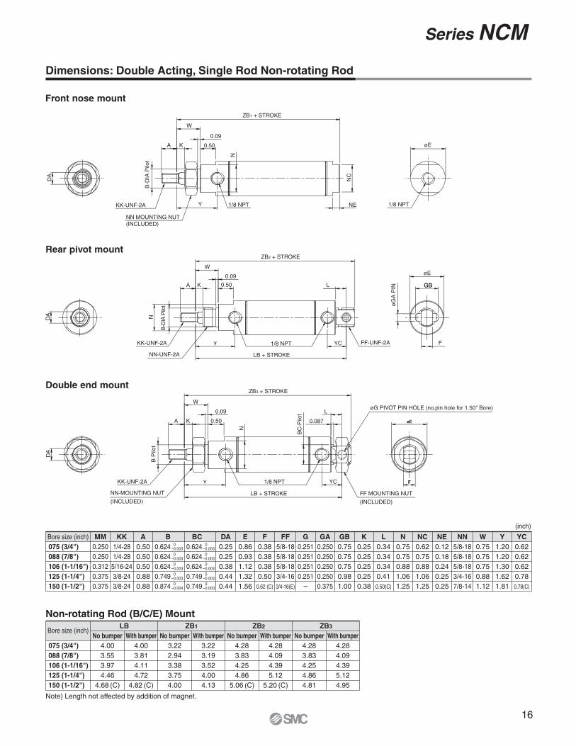
Dimensions: Double Acting, Single Rod Non-rotating Rod
Bore size (inch)075 (3/4")
088 (7/8")
106 (1-1/16")
125 (1-1/4")
150 (1-1/2")
MM
0.2500.2500.3120.3750.375
FF
5/8-185/8-185/8-183/4-163/4-16(E)
G
0.2510.2510.2510.251
–
GA
0.2500.2500.2500.2500.375
NN
5/8-185/8-185/8-183/4-167/8-14
A
0.500.500.500.880.88
DA
0.250.250.380.440.44
E
0.860.931.121.321.56
F
0.380.380.380.50
0.62 (C)
GB
0.750.750.750.981.00
K
0.250.250.250.250.38
L
0.340.340.340.410.50(C)
N
0.750.750.881.061.25
NC
0.620.750.881.061.25
NE
0.120.180.240.250.25
W
0.750.750.750.881.12
Y
1.201.201.301.621.81
YC
0.620.620.620.780.78(C)
B
0.6240.6240.6240.7490.874
KK
1/4-281/4-285/16-243/8-243/8-24
0–0.0030
–0.0030
–0.0030
–0.0030
–0.004
BC
0.6240.6240.6240.7490.749
0–0.0030
–0.0030
–0.0030
–0.0030
–0.003
(inch)
Bore size (inch)
075 (3/4")
088 (7/8")
106 (1-1/16")
125 (1-1/4")
150 (1-1/2")
No bumper
4.003.553.974.46
4.68 (C)
With bumper
4.003.814.114.72
4.82 (C)
Non-rotating Rod (B/C/E) Mount
Note) Length not affected by addition of magnet.
LB
No bumper
3.222.943.383.754.00
With bumper
3.223.193.524.004.13
ZB1
No bumper
4.283.834.254.86
5.06 (C)
With bumper
4.284.094.395.12
5.20 (C)
ZB2
No bumper
4.283.834.254.864.81
With bumper
4.284.094.395.124.95
ZB3
ZB1 + STROKE
1/8 NPT
W
KK-UNF-2A 1/8 NPT
0.09
0.50
NN MOUNTING NUT(INCLUDED)
DA
NC
NE
ZB2 + STROKE
1/8 NPTKK-UNF-2A
0.50
NN-UNF-2A
øG
A P
IN GB
FF-UNF-2AYC
LB + STROKE
DA
0.09
ZB3 + STROKE
KK-UNF-2A
0.09
0.50
NN-MOUNTING NUT
(INCLUDED)LB + STROKE FF MOUNTING NUT
(INCLUDED)
0.087
øG PIVOT PIN HOLE (no.pin hole for 1.50" Bore)
YC
BC
-Pilo
t
DA
1/8 NPT
Double end mount
Rear pivot mount
Front nose mount
B-D
IA P
ilot
B-D
IA P
ilot
B P
ilot
øE
øE
F
A GBK
N
W
A K
A K
L
W
N
Y
N
L
17
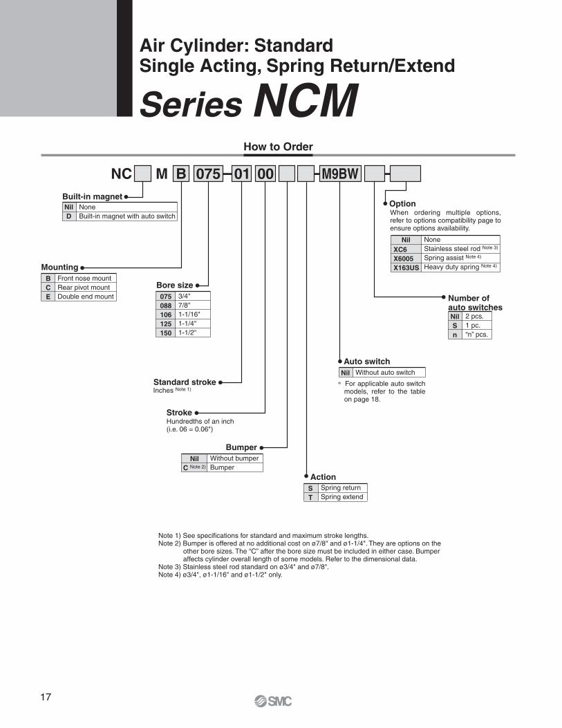
Air Cylinder: StandardSingle Acting, Spring Return/Extend
Series NCM
Mounting
Bore size
Inches Note 1)
Nil
D
NoneBuilt-in magnet with auto switch
Stroke
- - -
How to Order
NC M B 075 01 00 M9BW
Built-in magnet
Nil
C Note 2)
Without bumperBumper
Bumper
S
T
Spring returnSpring extend
Action
Nil Without auto switch
Auto switch
Nil
S
n
2 pcs.1 pc.“n” pcs.
075
088
106
125
150
3/4"7/8"1-1/16"1-1/4"1-1/2"
B
C
E
Front nose mountRear pivot mountDouble end mount
Standard stroke
Number of auto switches
Note 1) See specifications for standard and maximum stroke lengths.Note 2) Bumper is offered at no additional cost on ø7/8" and ø1-1/4". They are options on the
other bore sizes. The “C” after the bore size must be included in either case. Bumper affects cylinder overall length of some models. Refer to the dimensional data.
Note 3) Stainless steel rod standard on ø3/4" and ø7/8".Note 4) ø3/4", ø1-1/16" and ø1-1/2" only.
Option
Hundredths of an inch (i.e. 06 = 0.06")
Nil NoneStainless steel rod Note 3)
Spring assist Note 4) Heavy duty spring Note 4)
XC6
X6005
X163US
∗ For applicable auto switch models, refer to the table on page 18.
When ordering multiple options, refer to options compatibility page to ensure options availability.
18
Auto Switch Specifications
Series NCM
Applicable Auto Switches
∗ Lead wire length symbols: 0.5 m ·········· Nil (Example) M9NW 1 m ··········· M (Example) M9NWM 3 m ··········· L (Example) M9NWL 5 m ··········· Z (Example) M9NWZ None ··········· N (Example) H7CN
∗ Solid state switches marked with “�” are produced upon receipt of order.∗ D-B54, B64, and B59W cannot be mounted for bore size 044 and 056.
∗ For details about auto switches with pre-wired connector, refer to Best Pneumatics catalog.∗ D-A9�, M9�, M9�W are shipped together.
(Only switch mounting bracket is assembled at the time of shipment.)∗ D-M9�M and M9�VM which lead wire length is 1 m are available from July, 2008.
Type Special function Electricalentry
Grommet
Connector
Grommet
Wiring(Output)
3-wire (NPN)
3-wire (PNP)
2-wire
3-wire (NPN)
3-wire (PNP)
2-wire
4-wire (NPN)
Load voltage
DC
24 V
5 V, 12 V
12 V
5 V, 12 V
12 V
5 V, 12 V
AC
Lead wire length (m)
0.5(Nil)
�������—
�
�
�������
3(L)
���������
�
�������
1(M)
���—
���—
—
—
—
—
—
—
—
—
—
5(Z)
���������
—
—
—
�—
��—
None(N)
—
—
—
�—
—
—
—
—
—
—
—
—
—
��—
���—
�����
—
—
—
—
—
—
—
—
Applicableload
Pre-wiredconnector
IC circuit
—
—
ICcircuit
ICcircuit
Relay,PLC
Auto switch model
Diagnostic indication(2-color indication)
M9N
M9P
M9B
H7C
M9NW
M9PW
M9BW
H7BA
H7NF
A96
A93
A90
B54
B64
C73C
C80C
B59W
—
So
lid
sta
te s
wit
ch
Indic
ator
light
Yes
Water resistant (2-color indication)
With diagnostic output (2-color indication)
Grommet
Grommet
Connector
100 V
100 V or less
100 V, 200 V
200 V or less
—
24 V or less
—
3-wire(NPN equivalent)
2-wire 24 V
5 V
12 V
—
ICcircuit
IC circuit
—
—
Relay,PLC
Diagnostic indication (2-color indication)
———
Re
ed
sw
itch
Yes
None
Yes
None
Yes
None
Yes
Option Compatibility
Option Compatibility (1)
NCDM
S
T
C
XB6
XB7
XB9
XC6
B
C
E
R
Auto switch capableSpring returnSpring extendBumperHeat resistantCold resistantLow speedStainless steel rodFront nose mountRear pivot mountDouble end mountBlock mount
1, 61, 61, 6
1, 2, 61, 61, 61, 6
1, 3, 61, 61, 61, 6
1, 5, 6
–OOOSSNSOOOS
–NOSSNSOOOO
–OSSNOOOOO
O ······· Combination available to orderS ······· Available with special requestN ······· Not available
Note 1) Exclude ø2".Note 2) Bumper no additional charge on ø7/8" and ø1-1/4".Note 3) Stainless steel rod standard on ø7/16", ø9/16", ø3/4" and ø7/8". Use XC6
option to get stainless steel rod nut.Note 4) Block mount not available in ø7/8" and ø1-1/4".Note 5) Block, Auto switch capable, S and T only available as special. Note 6) Exclude ø7/16" and ø9/16".
NC
DM
S TDescription Note
Option Compatibility (2)
Single acting, Spring return (S), No bumperSingle acting, Spring return (S), With bumperSingle acting, Spring extend (T), No bumperSingle acting, Spring extend (T), With bumperDirect single acting, Spring return (S), No bumperDirect single acting, Spring extend (T), No bumperSingle acting, Spring extend (T), No bumper XC6Single acting, Spring extend (T), With bumper XC6
044 056 075
OOOOOOO
088
O
O
O
106
OOOOOOO
125
O
O
O
150
OOOOOOO
200
19
Series NCM
Specifications: Single Acting, Spring Return / Spring Extend
Fluid
Maximum operating pressure
Minimum operating pressure
Ambient and fluid temperature
Piston speed
Bumper
Lubrication
Mounting
Air
250 PSI / 1.7 MPa
25 PSI / 0.18 MPa
40 to 140°F / 5 to 60 °C
2 to 20 in/sec / 50 to 500 mm/s
Optional (No additional charge on 7/8" and 1-1/4" bore)
Note) R mount available on 3/4", 1-1/16", and 1-1/2" bore only.
Bore size (inch)
Specifications
Standard Stroke
Mounting
Front nose mount (B)
Rear pivot mount (C)
Double end mount (E)
Block mount (R)
Standard stroke
1/2, 1, 1-1/2, 2, 3, 4 6
Max. stroke
Note) Up to 18" available as special request.
(inch)
Note1) Force on extension (OUT) is shown as the theoretical force of a double acting cylinder on extension less the compressed force of the return spring.
Note 2) Force on retraction (IN) is the resting force of spring when fully retracted.
Theoretical Output: Spring Return (S) with Standard Rod
Bore size(inch)
075 (3/4")
088 (7/8")
106 (1-1/16")
125 (1-1/4")
150 (1-1/2")
Rod diameter(inch)
0.250
0.250
0.312
0.437
0.437
Operatingdirection
OUTIN
OUTIN
OUTIN
OUTIN
OUTIN
Effective area(sq.inch)
Operating pressure (PSI)
0.442–
0.608–
0.882–
1.227–
1.767–
25
8.0
12.2
19.1
23.7
37.2
(lbf)
50
19.1
27.4
41.1
54.4
81.4
75
30.1
42.6
63.2
85.0
125.5
100
41.2
57.8
85.2
115.7
169.7
3.0
3.0
3.0
7.0
7.0
125
52.2
73.0
107.3
146.4
213.9
150
63.3
88.2
129.4
177.1
258.1
Note1) Force on retraction (IN) is shown as the theoretical force of a double acting cylinder on retraction less the compressed force of the extend spring.
Note 2) Force on extension (OUT) is the resting force of spring when fully extended.
Theoretical Output: Spring Extend (T) with Standard Rod
Bore size(inch)
075 (3/4")
088 (7/8")
106 (1-1/16")
125 (1-1/4")
150 (1-1/2")
Rod diameter(inch)
0.25
0.25
0.312
0.437
0.437
Operatingdirection
OUTIN
OUTIN
OUTIN
OUTIN
OUTIN
Effective area(sq.inch)
Operating pressure (PSI)
–0.393
–0.559
–0.806
–1.077
–1.617
25
6.8
11.0
17.2
19.9
33.4
(lbf)
50
16.6
25.0
37.3
46.9
73.9
75
26.5
38.9
57.5
73.8
114.3
100
36.3
52.9
77.6
100.7
154.7
3.0
3.0
3.0
7.0
7.0
125
46.1
66.9
97.8
127.6
195.1
150
55.9
80.9
117.9
154.6
235.6
20
Series NCM
Specifications: Single Acting, Spring Return / Spring Extend
(lbs)
Bore size(inch)
Base weight by mounting style1st inchof stroke
Add’l weightper inch stroke
075 (3/4")
088 (7/8")
106 (1-1/16")
125 (1-1/4")
150 (1-1/2")
B
0.1480.1940.2930.5140.587
C
0.1640.1820.2870.5180.619
E
0.2240.2640.3690.6440.707
R B, C, E B, C, E, R
0.224N/A
0.430N/A
1.020
0.0440.0470.0630.1080.113
0.0780.0860.1120.2200.212
Add’l weightfor bumper
0.0060.0190.0380.0420.034
Add’l weightfor magnet
0.0080.0100.0120.0200.024
(lbs)
Spring Force: Spring Return (S) and Spring Extend (T) Type Cylinders
Weight: Single Acting, Spring Return except Non-rotating Rod
(lbs)
Bore size(inch)
Base weight by mounting style1st inchof stroke
Add’l weightper inch stroke
075 (3/4")
088 (7/8")
106 (1-1/16")
125 (1-1/4")
150 (1-1/2")
B
0.1970.2140.3370.5980.749
C
0.1710.1880.3110.5640.781
E
0.2530.2700.3930.6900.869
R B, C, E B, C, E, R
0.210N/A
0.430N/A
1.020
0.0440.0470.0630.1080.113
0.0710.0780.1160.1860.222
Add’l weightfor bumper
0.0060.0190.0380.0420.034
Add’l weightfor magnet
0.0080.0100.0120.0200.024
Weight: Single Acting, Spring Extend except Non-rotating Rod
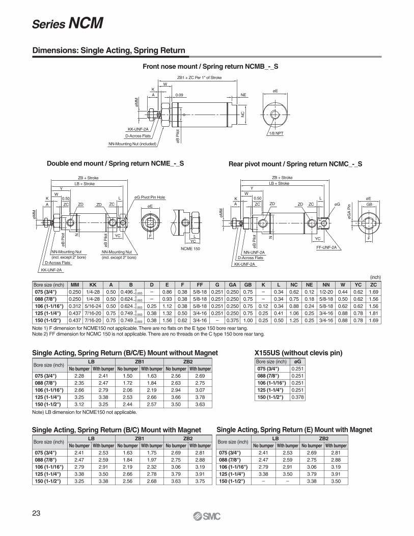
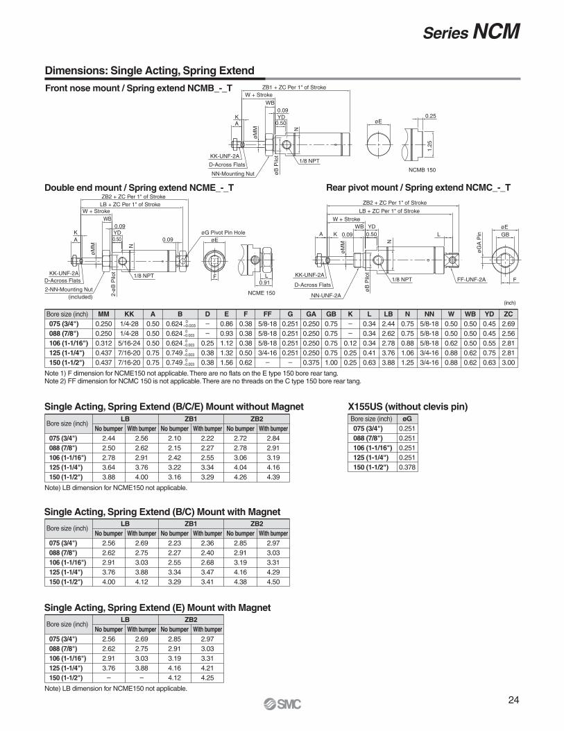
Note 1) F dimension for NCME150 not applicable. There are no flats on the E type 150 bore rear tang.Note 2) FF dimension for NCMC 150 is not applicable. There are no threads on the C type 150 bore rear tang.
LB
No bumper
1.501.722.062.532.44
With bumper
1.631.842.192.662.57
ZB1
No bumper
2.562.632.943.663.50
With bumper
2.692.753.073.783.63
ZB2
Bore size (inch)
075 (3/4")
088 (7/8")
106 (1-1/16")
125 (1-1/4")
150 (1-1/2")
No bumper
2.412.472.793.383.25
With bumper
2.532.592.913.503.38
LB
No bumper
1.631.842.192.662.56
With bumper
1.751.972.322.782.68
ZB1
No bumper
2.692.753.063.793.63
With bumper
2.812.883.193.913.75
ZB2
Bore size (inch)075 (3/4")
088 (7/8")
106 (1-1/16")
125 (1-1/4")
150 (1-1/2")
øG
0.2510.2510.2510.2510.378
Bore size (inch)
075 (3/4")
088 (7/8")
106 (1-1/16")
125 (1-1/4")
150 (1-1/2")
No bumper
2.412.472.793.38
–
With bumper
2.532.592.913.50
–
LB
No bumper
2.692.753.063.793.38
With bumper
2.812.883.193.913.50
ZB2
ZB1 + ZC Per 1" of Stroke
KK-UNF-2A
D-Across Flats
NN-Mounting Nut (included)
0.09
W
NE
1/8 NPT
NC
KA
øM
M
øB
Pilo
t
øE
Dimensions: Single Acting, Spring Return
ZB + StrokeLB + Stroke
øG
FF-UNF-2A
YW
ZCA
øM
M
KK-UNF-2A
D-Across FlatsNN-UNF-2A
øB
Pilo
t
N YC
øG
A P
in
øE
GB
F
L
ZCZDZDK 0.50
YC
ZB + StrokeLB + Stroke
øG Pivot Pin Hole
øE
NN-Mounting Nut(incl. except 2" bore)
NCME 150
ZD ZC
L
FYC
L
øB
Pilo
t
øB
Pilo
t
NN-Mounting Nut(incl. except 2" bore)
D-Across Flats
KK-UNF-2A
øM
M
ZC
0.50
A
KW
Y
ZD
N
Single Acting, Spring Return (B/C/E) Mount without Magnet X155US (without clevis pin)
Single Acting, Spring Return (E) Mount with MagnetSingle Acting, Spring Return (B/C) Mount with Magnet
24
Series NCM
Bore size (inch)075 (3/4")
088 (7/8")
106 (1-1/16")
125 (1-1/4")
150 (1-1/2")
MM
0.2500.2500.3120.4370.437
A
0.500.500.500.750.75
E
0.860.931.121.321.56
F
0.380.380.380.500.62
G
0.2510.2510.2510.251
–
GA
0.2500.2500.2500.2500.375
GB
0.750.750.750.751.00
K
––
0.120.250.25
L
0.340.340.340.410.63
LB
2.442.622.783.763.88
N
0.750.750.881.061.25
NN
5/8-185/8-185/8-183/4-163/4-16
W
0.500.500.620.880.88
WB
0.500.500.500.620.62
ZC
2.692.562.812.813.00
YD
0.450.450.550.750.63
FF
5/8-185/8-185/8-183/4-16
–
D
––
0.250.380.38
B
0.6240.6240.6240.7490.749
KK
1/4-281/4-285/16-247/16-207/16-20
0–0.0030
–0.0030
–0.0030
–0.0030
–0.003
(inch)
Bore size (inch)
075 (3/4")
088 (7/8")
106 (1-1/16")
125 (1-1/4")
150 (1-1/2")
No bumper
2.442.502.783.643.88
With bumper
2.562.622.913.764.00
Note) LB dimension for NCME150 not applicable.
Note 1) F dimension for NCME150 not applicable. There are no flats on the E type 150 bore rear tang.Note 2) FF dimension for NCMC 150 is not applicable. There are no threads on the C type 150 bore rear tang.
LB
No bumper
2.102.152.423.223.16
With bumper
2.222.272.553.343.29
ZB1
No bumper
2.722.783.064.044.26
With bumper
2.842.913.194.164.39
ZB2
Bore size (inch)
075 (3/4")
088 (7/8")
106 (1-1/16")
125 (1-1/4")
150 (1-1/2")
No bumper
2.562.622.913.76
–
With bumper
2.692.753.033.88
–
Note) LB dimension for NCME150 not applicable.
LB
No bumper
2.852.913.194.164.12
With bumper
2.973.033.314.214.25
ZB2
Bore size (inch)
075 (3/4")
088 (7/8")
106 (1-1/16")
125 (1-1/4")
150 (1-1/2")
No bumper
2.562.622.913.764.00
With bumper
2.692.753.033.884.12
LB
No bumper
2.232.272.553.343.29
With bumper
2.362.402.683.473.41
ZB1
No bumper
2.852.913.194.164.38
With bumper
2.973.033.314.294.50
ZB2
Bore size (inch)075 (3/4")
088 (7/8")
106 (1-1/16")
125 (1-1/4")
150 (1-1/2")
øG
0.2510.2510.2510.2510.378
Front nose mount / Spring extend NCMB_-_T
Double end mount / Spring extend NCME_-_T Rear pivot mount / Spring extend NCMC_-_T
Dimensions: Single Acting, Spring Extend
Single Acting, Spring Extend (B/C/E) Mount without Magnet X155US (without clevis pin)
Single Acting, Spring Extend (B/C) Mount with Magnet
Single Acting, Spring Extend (E) Mount with Magnet
ZB1 + ZC Per 1" of StrokeW + Stroke
WB0.09YD
0.50
KK-UNF-2A
D-Across Flats
NN-Mounting NutNCMB 150
0.25øE
1.25
1/8 NPT
øM
M
AK
øB
Pilo
t
N
1/8 NPT
ZB2 + ZC Per 1" of StrokeLB + ZC Per 1" of Stroke
W + StrokeWB
0.09YD0.50
2-ø
B P
ilot
2-NN-Mounting Nut(included)
KK-UNF-2AD-Across Flats
øM
M
AK
0.09 øEøG Pivot Pin Hole
F
NCME 150
0.91L
N
ZB2 + ZC Per 1" of Stroke
LB + ZC Per 1" of Stroke
1/8 NPT FF-UNF-2A
øB
Pilo
t
NN-UNF-2A
D-Across Flats
KK-UNF-2A
A K 0.09
øM
M
WB YD0.50
N
LøEGB
F
øG
A P
in
W + Stroke
25
Air Cylinder: Non-rotating RodSingle Acting, Spring Return
Series NCM
Mounting
Bore size
Inches Note 2)
Nil
D
NoneBuilt-in magnet with auto switch
Stroke
- - -
How to Order
NC MK B 075 01 00 M9BW
Built-in magnet
Non-rotating rod
Nil
C Note 3)
Without bumperBumper
Bumper
S Spring return
Action
Nil Without auto switch
Auto switch
Nil
S
n
2 pcs.1 pc.“n” pcs.
075
088
106
125
150
3/4"7/8"1-1/16"1-1/4"1-1/2"
B
C
E
Front nose mountRear pivot mountDouble end mount
Standard stroke
Number of auto switches
Note 1) Not available with double rod (W), block mount (R), rod boot.Note 2) See specifications for standard and maximum stroke lengths.Note 3) Bumper is offered at no additional cost on ø7/8" and ø1-1/4". They are options on the
other bore sizes. The “C” after the bore size must be included in either case. Bumper affects cylinder overall length of some models. Refer to the dimensional data.
Option
Hundredths of an inch (i.e. 06 = 0.06")
Nil NoneHeavy duty springX163US
∗ For applicable auto switch models, refer to the table on page 28.
When ordering multiple options, refer to options compatibility page to ensure options availability.
26
Auto Switch Specifications
Series NCM
Applicable Auto Switches
∗ Lead wire length symbols: 0.5 m ·········· Nil (Example) M9NW 1 m ··········· M (Example) M9NWM 3 m ··········· L (Example) M9NWL 5 m ··········· Z (Example) M9NWZ None ··········· N (Example) H7CN
∗ Solid state switches marked with “�” are produced upon receipt of order.∗ D-B54, B64, and B59W cannot be mounted for bore size 044 and 056.
∗ For details about auto switches with pre-wired connector, refer to Best Pneumatics catalog.∗ D-A9�, M9�, M9�W are shipped together.
(Only switch mounting bracket is assembled at the time of shipment.)∗ D-M9�M and M9�VM which lead wire length is 1 m are available from July, 2008.
Type Special function Electricalentry
Grommet
Connector
Grommet
Wiring(Output)
3-wire (NPN)
3-wire (PNP)
2-wire
3-wire (NPN)
3-wire (PNP)
2-wire
4-wire (NPN)
Load voltage
DC
24 V
5 V, 12 V
12 V
5 V, 12 V
12 V
5 V, 12 V
AC
Lead wire length (m)
0.5(Nil)
�������—
�
�
�������
3(L)
���������
�
�������
1(M)
���—
���—
—
—
—
—
—
—
—
—
—
5(Z)
���������
—
—
—
�—
��—
None(N)
—
—
—
�—
—
—
—
—
—
—
—
—
—
��—
���—
�����
—
—
—
—
—
—
—
—
Applicableload
Pre-wiredconnector
IC circuit
—
—
ICcircuit
ICcircuit
Relay,PLC
Auto switch model
Diagnostic indication(2-color indication)
M9N
M9P
M9B
H7C
M9NW
M9PW
M9BW
H7BA
H7NF
A96
A93
A90
B54
B64
C73C
C80C
B59W
—
So
lid
sta
te s
wit
ch
Indic
ator
light
Yes
Water resistant (2-color indication)
With diagnostic output (2-color indication)
Grommet
Grommet
Connector
100 V
100 V or less
100 V, 200 V
200 V or less
—
24 V or less
—
3-wire(NPN equivalent)
2-wire 24 V
5 V
12 V
—
ICcircuit
IC circuit
—
—
Relay,PLC
Diagnostic indication (2-color indication)
———
Re
ed
sw
itch
Yes
None
Yes
None
Yes
None
Yes
Option Compatibility
Option Compatibility (2)
Single acting, Spring return (S), Non-rotating rod, No bumperSingle acting, Spring return (S), Non-rotating rod, With bumper
044 056 075
OO
088
O
106
OO
125
O
150
OO
200
Option Compatibility (1)
NCMK-S
NCMK-T
C
B
C
E
Spring returnSpring extendBumperFront nose mountRear pivot mountDouble end mount
1, 31, 3
1, 2, 31, 31, 31, 3
–NOOOO
–OOOO
–OOO
O ······· Combination available to orderS ······· Available with special requestN ······· Not available
Note 1) Exclude ø2".Note 2) Bumper no additional charge on ø7/8" and ø1-1/4".Note 3) Exclude ø7/16" and ø9/16".
Description
NC
MK
-S
NC
MK
-T
CNote
27
Series NCM
Specifications: Single Acting, Spring Return Non-rotating Rod
Fluid
Maximum operating pressure
Minimum operating pressure
Ambient and fluid temperature
Piston speed
Rod material
Bumper
Non-rotating accuracy
Maximum allowable torque
Air
250 PSI / 1.7 MPa
25 PSI / 0.18 MPa
40 to 140°F / 5 to 60 °C
2 to 20 in/sec / 50 to 500 mm/s
Stainless steel 303
Optional (No additional charge on 7/8" and 1-1/4" bore)
Note 1) Minimum stroke for mounting auto switches: 0.6 inch for 2 switches, 0.4 inch for one switch.
Note 2) Spring return up to 18" available as special request.
Note1) Force on extension (OUT) is shown as the theoretical force of a double acting non-rotating rod cylinder on extension less the compressed force of the return spring.
Note 2) Force on retraction (IN) is the resting force of spring when fully retracted.
Theoretical Output
Bore size(inch)
075 (3/4")
088 (7/8")
106 (1-1/16")
125 (1-1/4")
150 (1-1/2")
Rod diameter(inch)
0.25
0.25
0.375
0.437
0.437
Operatingdirection
OUTIN
OUTIN
OUTIN
OUTIN
OUTIN
Effective area(sq.inch)
Operating pressure (PSI)
0.442–
0.608–
0.882–
1.227–
1.767–
25
8.0
12.2
19.1
23.7
37.2
(lbf)
50
19.1
27.4
41.1
54.4
81.4
75
30.1
42.6
63.2
85.0
125.5
100
41.2
57.8
85.2
115.7
169.7
3.0
3.0
3.0
7.0
7.0
125
52.2
73.0
107.3
146.4
213.9
150
63.3
88.2
129.4
177.1
258.1
(lbs)Weight
Bore size(inch)
Base weight by mounting style1st Inchof stroke
Add’l weightper inch stroke
075 (3/4")
088 (7/8")
106 (1-1/16")
125 (1-1/4")
150 (1-1/2")
B
0.1430.2160.2870.4900.582
C
0.1590.2040.2810.4940.574
E B, C, E B, C, E
0.2190.2860.3630.6200.742
0.0450.0470.0750.1120.118
0.0800.0860.1380.2240.248
Add’l weightfor bumper
0.0060.0190.0380.0420.032
Add’l weightfor magnet
0.0080.0100.0120.0200.024
28
Series NCM
Front nose mount / Spring return NCMB_-_S
Rear pivot mount / Spring return NCMC_-_SDouble end mount / Spring return NCME_-_S
Bore size (inch)075 (3/4")
088 (7/8")
106 (1-1/16")
125 (1-1/4")
150 (1-1/2")
E
0.860.931.121.321.56
F
0.380.380.380.500.62
G
0.2510.2510.2510.251
–
GA
0.2500.2500.2500.2500.375
GB
0.750.750.750.751.00
K
0.250.250.250.250.38
L
0.340.340.340.410.50
NC
0.620.750.881.061.25
NE
0.120.180.240.250.25
NN
1/2-205/8-185/8-183/4-163/4-16
W
0.690.750.750.881.00
YC
0.620.620.620.780.91
ZC
1.691.561.561.811.69
DA
0.250.250.380.440.44
A
0.500.500.500.880.88
B
0.4960.6240.6240.7490.749
KK
1/4-281/4-28
5/16-247/16-207/16-20
0–0.0030
–0.0030
–0.0030
–0.0030
–0.003
BC
0.6240.6240.6240.7490.749
0–0.0030
–0.0030
–0.0030
–0.0030
–0.003
Bore size (inch)
075 (3/4")
088 (7/8")
106 (1-1/16")
125 (1-1/4")
150 (1-1/2")
No bumper
2.53–
2.78–
3.25
With bumper
–
2.72–
3.38–
Note) LB dimension for NCME150 not applicable.
Note 1) F dimension for NCME150 not applicable. There are no flats on the E type 150 bore rear tang.Note 2) FF dimension for NCMC 150 is not applicable. There are no threads on the C type 150 bore rear tang.
LB
No bumper
1.75–
2.19–
2.56
With bumper
–
2.09–
2.66–
ZB1
No bumper
2.80–
3.06–
3.25
With bumper
–
3.00–
3.77–
ZB2
Bore size (inch)
075 (3/4")
088 (7/8")
106 (1-1/16")
125 (1-1/4")
150 (1-1/2")
No bumper
2.66–
2.92–
3.38
With bumper
–
2.85–
3.50–
LB
No bumper
1.88–
2.31–
2.69
With bumper
–
2.22–
2.78–
ZB1
No bumper
2.92–
3.19–
3.38
With bumper
–
3.13–
3.91–
ZB2
Bore size (inch)075 (3/4")
088 (7/8")
106 (1-1/16")
125 (1-1/4")
150 (1-1/2")
øG
0.2510.2510.2510.2510.378
Bore size (inch)
075 (3/4")
088 (7/8")
106 (1-1/16")
125 (1-1/4")
150 (1-1/2")
No bumper
2.66–
2.92––
With bumper
–
2.85–
3.50–
LB
No bumper
2.93–
3.19–
3.38
With bumper
–
3.13–
3.91–
ZB2
DA
K
KK-UNF-2A
A 0.09
NC
øE
NN Mounting Nut(included)
øB
Pilo
t
W
1/8 NPT
ZB1 + ZC per 1" of Stroke
NE
LB + ZC per 1" of Stroke
DA
KK-UNF-2A
KA
NN-UNF-2A
øE
øG
A P
IN
1/8 NPT YC
L
F
FF-UNF-2A
GB0.09
øB
Pilo
t
W
ZB2 + ZC per 1" of Stroke
øB
Pilo
t
LB + ZC per 1" of Stroke
DA
KK-UNF-2A
KA
1/8 NPT
øB
Pilo
t
YC
øEL
F
øG PIVOT PIN HOLE
0.09
FF MOUNTING NUT(included)
NN MOUNTING NUT(included)
0.09
W
ZB2 + ZC per 1" of Stroke
FF
5/8-185/8-185/8-183/4-163/4-16
(inch)
X155US (without clevis pin)Single Acting, Spring Return (B/C/E) Mount without Magnet
Single Acting, Spring Return (B/C) Mount with Magnet Single Acting, Spring Return (E) Mount with Magnet
Dimensions: Single Acting, Spring Return Non-rotating Rod
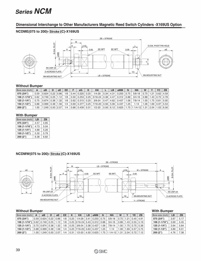
Dimensional Interchange to Other Manufacturers Magnetic Reed Switch Cylinders -X169US Option
NCDME(075 to 200)- Stroke (C)-X169US
Without Bumper
Bore size (inch)075 (3/4")
106 (1-1/16")
125 (1-1/4")
150 (1-1/2")
200 (2")
A
0.590.620.750.881.00
D
0.220.250.380.380.50
F
0.440.500.620.690.86
øG
0.2200.2530.3150.3770.439
KK
1/4-285/16-243/8-247/16-201/2-20
L
0.340.380.470.560.56
LB
4.314.474.625.066.12
øMM
0.2500.3120.4370.4370.625
N
0.750.881.061.251.75
NN
5/8-183/4-167/8-141-14
1 1/4-12
Y
1.211.431.751.692.04
YC
0.620.720.810.971.03
ZB
4.594.785.005.536.56
W
0.750.881.001.061.31
K
0.250.250.250.250.31
EE
1/81/81/81/41/4
øE
0.861.121.321.562.07
øB
0.6240.7490.8740.9991.249
With Bumper
Bore size (inch)075 (3/4")
106 (1-1/16")
125 (1-1/4")
150 (1-1/2")
200 (2")
LB
4.574.734.885.326.38
ZB
4.855.045.265.796.82
With Bumper
Bore size (inch)075 (3/4")
106 (1-1/16")
125 (1-1/4")
150 (1-1/2")
200 (2")
LB
3.673.693.643.894.76
ZB
5.175.455.646.017.38
ZB + STROKE
LB + STROKE
YC
L
0.09
N
B-D
IA. P
ILO
T
Y
W
0.09A
øM
M
K
EE NPT
0.50
EE NPT
G-DIA. PIVOT PIN HOLE
øE
NN-MOUNTING NUT
F
NN-MOUNTING NUT
KK-UNF-2A
D-ACROSS FLATS
NCDMW(075 to 200)- Stroke (C)-X169US
Without Bumper
Bore size (inch)075 (3/4")
106 (1-1/16")
125 (1-1/4")
150 (1-1/2")
200 (2")
A
0.590.620.750.881.00
D
0.220.250.380.380.50
K
0.250.250.250.250.31
KK
1/4-285/16-243/8-24
7/16-201/2-20
N
0.750.881.061.251.75
LB
3.413.433.383.634.50
NN
5/8-183/4-167/8-141-14
1 1/4-12
W
0.750.881.001.061.31
YE
0.450.550.750.570.72
Y
1.211.431.751.692.04
ZB
4.915.195.385.757.12
øMM
0.2500.3120.4370.4370.625
EE
1/81/81/81/41/4
øE
0.861.121.321.562.07
øB
0.6240.7490.8740.9991.249
B-D
IA. P
ILO
T
ZB + STROKE
Y + STROKE
W + STROKE
0.09
øE
N
Y
LB + STROKE
YE
0.50
0.09
B-D
IA. P
ILO
T W
K
A
øM
M
EE NPT EE NPT
YE
0.50
NN-MOUNTING NUT
A
KK-UNF-2A
D-ACROSS FLATS
øM
M
NN-MOUNTING NUT
D-ACROSS FLATS
KK-UNF-2A
40
Series NCM
Air Tank -X6002 Option
(inch)
(cubic inch)
Specifications
FluidMax. operating pressureMounting
Bore size (inch)
Mounting
Air250 PSI / 1.7 MPa
B, E
NCMB(075 to 200)- Stroke -X6002
Standard Length
Front nose (B)Double end mount (E)
1, 2, 3, 4, 5, 6
Max. lengthStandard length
38
How to Order
Mounting Bore Stroke X6002
Ex.) NCMB075-0400-X6002
Without Bumper
Bore size (inch)075 (3/4")
088 (7/8")
106 (1-1/16")
125 (1-1/4")
150 (1-1/2")
200 (2")
øE
0.860.931.121.321.562.06
NE
0.120.180.250.250.250.31
Volume (Cubic inches)0.51 + 0.44 per inch of length0.45 + 0.60 per inch of length0.95 + 0.88 per inch of length1.19 + 1.22 per inch of length1.83 + 1.77 per inch of length3.48 + 3.14 per inch of length
Standard length0.51 + 0.44 per inch of length0.45 + 0.60 per inch of length0.95 + 0.88 per inch of length1.19 + 1.22 per inch of length1.83 + 1.77 per inch of length3.48 + 3.14 per inch of length0.68 + 0.44 per inch of length0.61 + 0.60 per inch of length1.08 + 0.88 per inch of length1.25 + 1.22 per inch of length1.91 + 1.77 per inch of length4.81 + 3.14 per inch of length
2-ZD NPT
NE
NC
øENE
ZB + LENGTH
41
Series NCM
Air Tank -X6002 Option
NCME(075 to 200)- Stroke -X6002
øE
2-F
ZB + LENGTH
LB + LENGTH
2-NN MOUNTING NUT 2-øG PIVOT PIN HOLE
L L
ZC ZC2-ZD NPT
Without Bumper
Bore size (inch)075 (3/4")
088 (7/8")
106 (1-1/16")
125 (1-1/4")
150 (1-1/2")
200 (2")
øE
0.860.931.121.321.562.06
øG
0.2510.2510.2510.2510.3750.375
Volume (Cubic inches)0.68 + 0.44 per inch of length0.61 + 0.60 per inch of length1.08 + 0.88 per inch of length1.25 + 1.22 per inch of length1.91 + 1.77 per inch of length4.81 + 3.14 per inch of length
LB
3.502.973.333.64
–4.67
L
0.340.340.340.410.630.56
NN
5/8-185/8-185/8-183/4-163/4-16
1 1/4-12
ZB
4.063.533.894.433.885.54
ZC
0.090.090.090.090.090.12
ZD
1/81/81/81/81/81/4
F
0.380.380.380.500.620.75
42
Series NCM
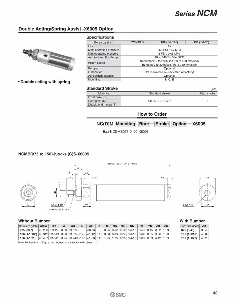
Double Acting/Spring Assist -X6005 Option
(inch)
Specifications
FluidMax. operating pressureMin. operating pressureAmbient and fluid temp.
Bore size (inch)
Mounting
Air250 PSI / 1.7 MPa8 PSI / 0.06 MPa
40 to 140°F / 5 to 60°CNo bumper: 2 to 20 in/sec (50 to 500 mm/sec)
Bumper: 2 to 30 in/sec (50 to 750 mm/sec)Optional
Not required (Pre-lubricated at factory)OptionalB, C, E
NCMB(075 to 150)- Stroke (C)S-X6005
Standard Stroke
Front nose (B)Rear pivot (C) Double end mount (E)
1/2, 1, 2, 3, 4, 5, 6
Max. strokeStandard stroke
6
How to Order
Mounting Bore Stroke Option X6005
Ex.) NCDMB075-0400-X6005
Without Bumper With Bumper
Bore size (inch)075 (3/4")
106 (1-1/16")
150 (1-1/2")
øMM
ø0.250ø0.312ø0.437
Bore size (inch)075 (3/4")
106 (1-1/16")
150 (1-1/2")
ZB
3.044.084.62
A
0.500.500.75
øE
ø0.86ø1.12ø1.56
K
–
0.120.25
NC
0.620.881.25
NE
0.120.240.25
NN
5/8-185/8-183/4-16
W
0.500.620.88
YD
0.450.550.63
ZB
3.023.864.42
ZC
1.691.561.69
N
0.750.881.25
D
–
0.250.38
øB
ø0.624ø0.624ø0.749
KK
1/4-285/16-247/16-20
• Double acting with spring
NC(D)M
075 (3/4") 106 (1-1/16") 150 (1-1/2")
Piston speed
BumperLubricationAuto switch capableMounting
A
K
W
0.09
0.5
ZB+ZC PER 1" OF STROKE
YD
NE
NC
øE
2-1/8 NPTKK-UNF-2A
D-ACROSS FLATS
øM
M
øB
N
Note: For fractions 1/2" go to next highest whole stroke and subtract 1/2".
43
Series NCM
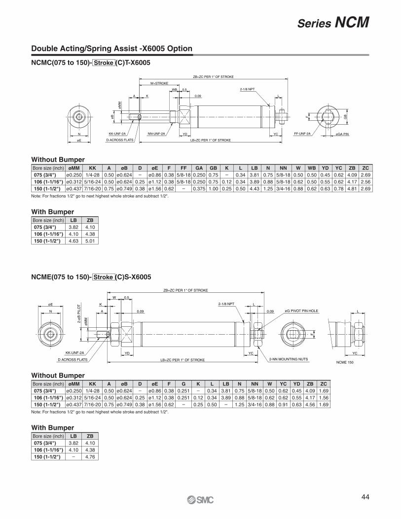
Double Acting/Spring Assist -X6005 Option
NCMB(075 to 150)- Stroke (C)T-X6005
NCMC(075 to 150)- Stroke (C)S-X6005
A K
W+STROKE
0.09
0.5
ZB+ZC PER 1" OF STROKE
YD
NE
NC
øE
2-1/8 NPTKK-UNF-2A
D-ACROSS FLATS
øM
M
øB
N NN-MOUNTING NUT
Without Bumper With Bumper
Bore size (inch)075 (3/4")
106 (1-1/16")
150 (1-1/2")
øMM
ø0.250ø0.312ø0.437
Bore size (inch)075 (3/4")
106 (1-1/16")
150 (1-1/2")
ZB
3.044.084.62
A
0.500.500.75
øE
ø0.86ø1.12ø1.56
K
–
0.120.25
NC
0.620.881.25
NE
0.120.240.25
NN
5/8-185/8-183/4-16
W
0.500.620.88
YD
0.450.550.63
ZB
3.023.864.42
ZC
2.692.562.69
N
0.750.881.25
D
–
0.250.38
øB
ø0.624ø0.624ø0.749
KK
1/4-285/16-247/16-20
Note: For fractions 1/2" go to next highest whole stroke and subtract 1/2".
Without Bumper
Bore size (inch)075 (3/4")
106 (1-1/16")
150 (1-1/2")
øMM
ø0.250ø0.312ø0.437
A
0.500.500.75
øE
ø0.86ø1.12ø1.56
F
0.380.380.62
GA
0.2500.2500.375
GB
0.750.751.00
K
–
0.120.25
L
0.340.340.50
LB
3.813.894.43
N
0.750.881.25
NN
5/8-185/8-183/4-16
FF
5/8-185/8-18
–
D
–
0.250.38
øB
ø0.624ø0.624ø0.749
KK
1/4-285/16-247/16-20
Note: For fractions 1/2" go to next highest whole stroke and subtract 1/2".
A
K
0.09
0.5
W
ZB+ZC PER 1" OF STROKE
L
YD YC
LB+ZC PER 1" OF STROKE
øM
M
øB
N
øE
KK-UNF-2A
D-ACROSS FLATS
2-NN-UNF-2A
2-1/8 NPT
GBF
øGA PINFF-UNF-2A
With Bumper
Bore size (inch)075 (3/4")
106 (1-1/16")
150 (1-1/2")
LB
3.824.104.63
ZB
4.104.385.01
W
0.500.620.88
YD
0.450.550.63
YC
0.620.620.78
ZB
4.094.174.81
ZC
1.691.561.69
44
Series NCM
Double Acting/Spring Assist -X6005 Option
NCME(075 to 150)- Stroke (C)S-X6005
NCMC(075 to 150)- Stroke (C)T-X6005
A K 0.09
0.5
W+STROKE
ZB+ZC PER 1" OF STROKE
L
YD YC
LB+ZC PER 1" OF STROKE
øM
M
øB
N
øE
KK-UNF-2A
D-ACROSS FLATS
NN-UNF-2A
2-1/8 NPT
GBF
øGA PINFF-UNF-2A
WB
Without Bumper
Bore size (inch)075 (3/4")
106 (1-1/16")
150 (1-1/2")
øMM
ø0.250ø0.312ø0.437
A
0.500.500.75
øE
ø0.86ø1.12ø1.56
F
0.380.380.62
GA
0.2500.2500.375
GB
0.750.751.00
K
–
0.120.25
L
0.340.340.50
LB
3.813.894.43
N
0.750.881.25
W
0.500.620.88
NN
5/8-185/8-183/4-16
FF
5/8-185/8-18
–
D
–
0.250.38
øB
ø0.624ø0.624ø0.749
KK
1/4-285/16-247/16-20
Note: For fractions 1/2" go to next highest whole stroke and subtract 1/2".
With Bumper
Bore size (inch)075 (3/4")
106 (1-1/16")
150 (1-1/2")
LB
3.824.104.63
ZB
4.104.385.01
WB
0.500.500.62
YD
0.450.550.63
YC
0.620.620.78
ZB
4.094.174.81
ZC
2.692.562.69
A
K
0.09
0.5W
ZB+ZC PER 1" OF STROKE
0.09
L2-1/8 NPT
YCYD
LB+ZC PER 1" OF STROKE
N
øE
øM
M
2-ø
B P
ILO
T
KK-UNF-2A
D ACROSS FLATS 2-NN MOUNTING NUTS
FøG PIVOT PIN HOLE
YC
L
NCME 150
Without Bumper
Bore size (inch)075 (3/4")
106 (1-1/16")
150 (1-1/2")
øMM
ø0.250ø0.312ø0.437
A
0.500.500.75
øE
ø0.86ø1.12ø1.56
F
0.380.380.62
K
–
0.120.25
L
0.340.340.50
LB
3.813.89
–
N
0.750.881.25
W
0.500.620.88
NN
5/8-185/8-183/4-16
G
0.2510.251
–
D
–
0.250.38
øB
ø0.624ø0.624ø0.749
KK
1/4-285/16-247/16-20
Note: For fractions 1/2" go to next highest whole stroke and subtract 1/2".
With Bumper
Bore size (inch)075 (3/4")
106 (1-1/16")
150 (1-1/2")
LB
3.824.10
–
ZB
4.104.384.76
YC
0.620.620.91
YD
0.450.550.63
ZB
4.094.174.56
ZC
1.691.561.69
45
Series NCM
Double Acting/Spring Assist -X6005 Option
NCME(075 to 150)- Stroke (C)T-X6005
Without Bumper
Bore size (inch)075 (3/4")
106 (1-1/16")
150 (1-1/2")
øMM
ø0.250ø0.312ø0.437
A
0.500.500.75
øE
ø0.86ø1.12ø1.56
F
0.380.38
–
K
–
0.120.25
L
0.340.340.63
LB
3.813.89
–
N
0.750.881.25
W
0.500.620.88
NN
5/8-185/8-183/4-16
G
0.2510.251
–
D
–
0.250.38
øB
ø0.624ø0.624ø0.749
KK
1/4-285/16-247/16-20
Note: For fractions 1/2" go to next highest whole stroke and subtract 1/2".
With Bumper
Bore size (inch)075 (3/4")
106 (1-1/16")
150 (1-1/2")
LB
3.024.10
–
ZB
4.104.384.76
YD
0.450.550.63
YC
0.620.620.91
ZB
4.094.174.56
ZC
2.692.562.69
A K 0.09
0.5W+STROKE
ZB+ZC PER 1" OF STROKE
0.09
L2-1/8 NPT
YCYD
LB+ZC PER 1" OF STROKE
N
øE
øM
M
2-ø
B P
ILO
T
KK-UNF-2A
D ACROSS FLATS 2-NN MOUNTING NUTS
F
øG PIVOT PIN HOLE
NCME 150
L
YC
46
Series NCM
Accessories
Foot bracket
NCM-L044
NCM-L075∗
NCM-L150
NCMK-L150
NCM-L200
7/16", 9/16"
3/4", 7/8", 1-1/16"
1-1/4", 1-1/2"
1-1/2" (Non-rotating)
2"
1.38
1.89
2.52
2.52
3.126
Part no. Applicable bore size A
0.56
0.81
1.00
1.00
1.50
B
0.83
1.36
1.75
1.75
2.5
C
0.09
0.12
0.12
0.12
0.25
D
0.44
0.63
0.75
0.88
1.38
E
0.50
0.75
0.94
0.94
1.13
F
0.19
0.27
0.27
0.27
0.34
G
0.69
0.98
1.50
1.50
1.63
H
0.38
0.56
0.75
0.75
1.00
J
(inch)
Note) NCM-L075 will not fit NCM∗075∗S (Single acting). For this option use: NCM075-19-51046. (F dimension=0.51")
NY-044
NY-075
NY-106
NY-125
NY-G050
7/16", 9/16"
3/4", 7/8"
1-1/16"
1-1/4", 1-1/2"
2"
0.38
0.51
0.51
0.75
0.75
Part no. Applicable bore size A
No.10-32
1/4-28
5/16-24
7/16-20
1/2-20
B
0.75
0.94
0.94
1.31
1.32
C
0.94
1.18
1.18
1.69
1.69
D
0.56
0.69
0.69
0.94
0.94
E
0.19
0.25
0.25
0.38
0.38
F
0.38
0.51
0.51
0.75
0.75
G
0.56
0.71
0.71
1.02
1.02
H
0.19
0.25
0.25
0.38
0.38
J
0.12
0.16
0.19
0.25
0.31
K
No.10-32
1/4-28
5/16-24
7/16-20
1/2- 20
L
(inch)
JM-02 Note 1)
JM-025
JM-03
JM-045
JM-04
JM-05 Note 1)
7/16", 9/16"
3/4", 7/8"
1-1/16"
1-1/4", 1-1/2"
1-1/4", 1-1/2" (Non-rotating)
2"
0.38
0.44
0.50
0.69
0.56
0.75
Part no. Applicable bore size A
0.43
0.51
0.50
0.79
0.65
0.87
B
0.13
0.16
0.19
0.26
0.23
0.32
C
No.10-32 UNF
1/4-28 UNF
5/16-24 UNF
7/16-20 UNF
3/8-24 UNF
1/2-20 UNF
D
(inch)
Note 1) Please order separately. (044, 056, 200 only)
J
AFF
øE
G H
C
D
B
D
C
B
A
E
øJ K
L
H G F
A C
D
B
Jam nut (Rod thread)
Rod clevis
47
Series NCM
Accessories
Pivot bracket (Rear pivot): NCMC
Pivot bracket (End mount): NCME
NCM-PC044
NCM-PC075
NCM-PC150
7/16", 9/16"
3/4", 7/8", 1-1/16", 1-1/4"
1-1/2"
0.50
0.75
1.00
Part no. Applicable bore size A
0.12
0.18
0.25
B
0.19
0.27
0.27
C
0.19
0.27
0.27
D
0.28
0.44
0.62
E
0.50
0.79
0.98
F
0.28
0.44
0.62
G
0.50
0.79
0.98
H
0.75
1.101
1.50
J
0.06
0.12
0.12
K
0.56
0.88
1.38
L
0.77
1.18
1.75
M
0.20
0.31
0.38
N
0.16
0.26
0.38
øP
(inch)
NCM-PE056
NCM-PE075
NCM-PE125
NCG-PCø5ø
9/16"
3/4", 7/8" 1-1/16"
1-1/4"
2"
0.91
1.25
1.38
2.12
Part no. Applicable bore size A
1.35
1.95
2.08
3.00
B
0.22
0.35
0.35
0.44
C
0.35
0.38
0.50
0.75
D
0.19
0.27
0.27
0.26
øE
0.16
0.25
0.25
0.38
F
0.06
0.12
0.12
0.24
G
0.77
1.18
1.18
1.75
H
0.56
0.88
0.88
1.38
J
0.50
0.75
0.75
1.00
K
0.75
1.10
1.10
1.50
L
0.12
0.18
0.18
0.25
M
0.20
0.31
0.31
0.37
N
(inch)
Mounting nut (Nose mount thread)
JM-045
JM-08
JM-10
JM-14
7/16", 9/16"
3/4", 7/8" 1-1/16"
1-1/4", 1-1/2"
2"
0.69
0.94
1.12
1.61
Part no. Applicable bore size A
0.79
1.08
1.30
1.86
B
0.26
0.38
0.42
0.43
C
7/16-20 UNF
5/8-18 UNF
3/4-16 UNF
1-1/4 -12 UNF
D
(inch)
N Radius
C D K
L
MFHG E
øP
JAB
øF
Pin
øE Slot
BAC
DN
HJ
KL
M
G
D
B
A C
48
Series NCM
Auto Switch Proper Mounting Position and Its Mounting Height (Single rod)
D-C7/C8
D-C73C/C80C
D-B5/B6/B59W
D-M9�(V)/M9�W(V)D-A9�(V)
BA 0.88
(0.98)
0.66
= HS
( ):D-A93
BA 0.88
0.66
= HS
= HS
BA 0.88
0.66
SMC SM
C
In case of NCDMC, NCDME
1.02A B
0.63
≅ HS
0.96
1.30A B
≅ HS
1.45
0.63
≅ HS
A B
D-H7C
D-G5NTL
D-H7�/H7�W/H7NF/H7BAL�
SMC
SMC
SMC
SMC
1.140.
63A B
≅ HS
0.96
1.30
≅ HS
A B
1.50
0.63
≅ HS
A B
B
49
Series NCM
Mounting Height (NCDM)
044 (7/16")
056 (9/16")
075 (3/4")
088 (7/8")
106 (1-1/16")
125 (1-1/4")
150 (1-1/2")
200 (2")
≅HS
0.7 0.770.850.910.961.061.181.44
≅HS
0.720.790.870.930.981.081.201.46
≅HS
0.830.9 0.981.041.141.241.361.61
≅HS
0.810.880.961.021.121.221.341.59
≅HS
––
0.981.041.141.241.361.61
Autoswitchmodel
Bore size
D-M9�D-M9�WD-A9�D-A9�V
D-M9�VD-M9�WVD-H7�D-H7�WD-H7BALD-H7NFD-C7�D-C80
D-H7C D-C73CD-C80C
D-G5NTLD-B5�D-B59WD-B64
(in)
Auto Switch Proper Mounting Position and Its Mounting Height (Single rod)
Auto Switch Mounting Position (NCDMB)
044 (7/16")
056 (9/16")
075 (3/4")
088 (7/8")
106 (1-1/16")
125 (1-1/4")
150 (1-1/2")
200 (2")
A
1.4 1.211.251.091.311.541.441.89
B
0.520.540.730.620.830.820.871.14
A
1.241.051.100.941.161.391.291.74
B
0.360.380.580.460.680.670.710.98
A
1.221.031.080.921.141.371.271.72
B
0.340.360.560.450.660.650.700.97
A
1.261.071.120.961.181.411.311.75
B
0.380.4 0.600.490.700.690.741.01
A
––
0.940.781.001.231.131.58
B
––
0.420.310.520.510.560.83
A
––
0.880.720.941.171.071.52
B
––
0.370.250.460.460.50.77
Autoswitchmodel
Bore size
D-M9�D-M9�W
D-A9� D-H7�D-H7�WD-H7CD-H7BALD-H7NF
D-C7�D-C80D-C73CD-C80C
D-G5NTL D-B5�D-B64
A
––
1.000.841.061.291.191.63
B
––
0.480.370.580.570.610.88
D-B59W
(in) Auto Switch Mounting Position (NCDMB-*C)
044 (7/16")
056 (9/16")
075 (3/4")
088 (7/8")
106 (1-1/16")
125 (1-1/4")
150 (1-1/2")
200 (2")
A
1.4 1.211.291.221.381.671.512.02
B
0.550.560.710.750.900.950.941.27
A
1.241.051.131.061.231.511.361.86
B
0.390.4 0.560.590.750.800.781.11
A
1.221.031.121.051.271.501.401.85
B
0.370.380.540.580.790.780.831.10
A
1.061.071.161.091.311.541.441.88
B
0.410.420.580.620.830.820.871.14
A
––
0.980.911.131.361.261.71
B
––
0.40.440.650.640.690.96
A
––
0.920.851.071.301.201.65
B
––
0.350.380.590.590.630.90
Autoswitchmodel
Bore size
D-M9�D-M9�W
D-A9� D-H7�D-H7�WD-H7CD-H7BALD-H7NF
D-C7�D-C80D-C73CD-C80C
D-G5NTL D-B5�D-B64
A
––
1.030.971.191.421.321.76
B
––
0.460.5
0.710.7
0.741.01
D-B59W
(in)
Auto Switch Mounting Position (NCDMC, NCDME)
044 (7/16")
056 (9/16")
075 (3/4")
088 (7/8")
106 (1-1/16")
125 (1-1/4")
150 (1-1/2")
200 (2")
A
1.4 1.211.251.091.311.541.441.89
B
1.211.1 1.170.901.071.161.071.51
A
1.241.051.100.941.161.391.291.74
B
1.050.441.020.750.921.010.921.36
A
1.221.031.080.921.141.371.271.72
B
1.030.971.000.720.900.980.891.34
A
1.261.071.120.961.181.411.311.75
B
1.070.961.030.760.941.020.931.38
A
––
0.940.781.001.231.131.58
B
––
0.860.590.760.850.751.20
A
––
0.880.720.941.171.071.52
B
––
0.80.530.70.790.71.14
Autoswitchmodel
Bore size
D-M9�D-M9�W
D-A9� D-H7�D-H7�WD-H7CD-H7BALD-H7NF
D-C7�D-C80D-C73CD-C80C
D-G5NTL D-B5�D-B64
A
––
1.000.841.061.291.191.63
B
––
0.910.640.810.900.811.25
D-B59W
(in) Auto Switch Mounting Position (NCDMC-*C, NCDME-*C)
044 (7/16")
056 (9/16")
075 (3/4")
088 (7/8")
106 (1-1/16")
125 (1-1/4")
150 (1-1/2")
200 (2")
A
1.4 1.211.291.221.381.671.512.02
B
1.241.121.151.031.201.291.201.64
A
1.241.051.131.061.231.511.361.86
B
1.080.961.000.881.051.141.051.49
A
1.221.031.121.051.271.501.401.85
B
1.060.940.980.851.031.111.021.47
A
1.261.071.161.091.311.541.441.88
B
1.1 0.981.010.891.071.151.061.51
A
––
0.980.911.131.361.261.71
B
––
0.840.720.890.980.881.33
A
––
0.920.851.071.301.201.65
B
––
0.780.660.830.920.831.27
Autoswitchmodel
Bore size
D-M9�D-M9�W
D-A9� D-H7�D-H7�WD-H7CD-H7BALD-H7NF
D-C7�D-C80D-C73CD-C80C
D-G5NTL D-B5�D-B64
A
––
1.030.971.191.421.321.76
B
––
0.890.770.941.030.941.38
D-B59W
(in)
Note 1) D-G5NTL, B5�, B64, B59W cannot be mounted on models with bore size 044 and 056.Note 2) When setting an auto switch, confirm the operation and adjust its mounting position.
50
Series NCM
Mounting Height (NCDMW)
075 (3/4")
088 (7/8")
106 (1-1/16")
125 (1-1/4")
150 (1-1/2")
200 (2")
≅HS
0.850.910.961.061.181.44
≅HS
0.870.930.981.081.201.46
≅HS
0.981.041.141.241.361.61
≅HS
0.961.021.121.221.341.59
≅HS
0.981.041.141.241.361.61
Autoswitchmodel
Bore size
D-M9�D-M9�WD-A9�D-A9�V
D-M9�VD-M9�WVD-H7�D-H7�WD-H7BALD-H7NFD-C7�D-C80
D-H7C D-C73CD-C80C
D-G5NTLD-B5�D-B59WD-B64
(in)
Auto Switch Mounting Position (NCDMW)
075 (3/4")
088 (7/8")
106 (1-1/16")
125 (1-1/4")
150 (1-1/2")
200 (2")
A
1.251.091.311.541.441.89
B
1.261.091.321.511.441.82
A
1.100.941.161.391.291.74
B
1.110.941.171.361.291.67
A
1.080.921.141.371.271.72
B
1.090.911.141.341.271.65
A
1.120.961.181.411.311.75
B
1.130.951.181.381.311.69
A
0.940.781.001.231.131.58
B
0.950.771.011.201.131.51
A
0.880.720.941.171.071.52
B
0.890.720.951.141.071.45
Autoswitchmodel
Bore size
D-M9�D-M9�W
D-A9� D-H7�D-H7�WD-H7CD-H7BALD-H7NF
D-C7�D-C80D-C73CD-C80C
D-G5NTL D-B5�D-B64
A
1.000.841.061.291.191.63
B
1.000.831.061.261.181.57
D-B59W
(in)
D-M9�(V)/M9�W(V)D-A9�(V)
Auto Switch Proper Mounting Position and Its Mounting Height (Double rod)
SMC SM
C
1.02A0.63
≅ HS
0.96
1.30A
≅ HS
1.450.63
≅ HS
A
B
B
B
D-C73C/C80C
D-B5/B6/B59W
SM
C
SM
C
SMC
SMC
(1.42)1.140.
63
A
≅ HS
0.96
1.30
≅ HS
A
1.500.63
≅ HS
A
B
B
B
D-H7C
D-G5NTL
D-H7�/H7�W/H7NF/H7BAL�
D-C7/C8
A 0.88
0.66
0.66
≅ HS
B(0.98) ( ):D-A93
A 0.88
≅ HS
≅ HS
B
Note 1) D-G5NTL, B5�, B64, B59W cannot be mounted on models with bore size 044 and 056.Note 2) When setting an auto switch, confirm the operation and adjust its mounting position.
Auto Switch Mounting Position (NCDMW-*C)
075 (3/4")
088 (7/8")
106 (1-1/16")
125 (1-1/4")
150 (1-1/2")
200 (2")
A
1.291.221.381.671.512.02
B
1.241.221.391.641.511.95
A
1.141.071.231.521.361.87
B
1.091.071.231.491.351.80
A
1.121.051.211.501.341.85
B
1.071.041.211.471.331.78
A
1.161.091.251.541.381.88
B
1.111.081.251.511.371.82
A
0.980.911.071.361.201.71
B
0.930.91.071.331.191.64
A
0.920.851.011.301.141.65
B
0.870.851.011.271.141.58
Autoswitchmodel
Bore size
D-M9�D-M9�W
D-A9� D-H7�D-H7�WD-H7CD-H7BALD-H7NF
D-C7�D-C80D-C73CD-C80C
D-G5NTL D-B5�D-B64
A
1.030.971.121.421.251.76
B
0.980.961.131.391.251.7
D-B59W
(in)
0.66
A 0.88 B
51
Series NCM
Auto Switch Proper Mounting Position and Its Mounting Height (Block mount)
Auto Switch Mounting Position (NCDMR)
075 (3/4")
106 (1-1/16")
150 (1-1/2")
A
1.671.982.47
B
0.740.830.87
A
1.521.832.32
B
0.590.680.72
A
1.501.812.29
B
0.560.660.70
A
1.541.852.33
B
0.600.700.74
A
1.361.672.16
B
0.420.520.56
A
1.301.612.10
B
0.370.460.50
Autoswitchmodel
Bore size
D-M9�D-M9�W
D-A9� D-H7�D-H7�WD-H7CD-H7BALD-H7NF
D-C7�D-C80D-C73CD-C80C
D-G5NTL D-B5�D-B64
A
1.421.722.21
B
0.480.580.61
D-B59W
(in)
Auto Switch Mounting Position (NCDMR-*C)
075 (3/4")
106 (1-1/16")
150 (1-1/2")
A
1.671.982.47
B
0.740.830.87
A
1.521.832.32
B
0.590.680.72
A
1.501.812.29
B
0.560.660.70
A
1.541.852.33
B
0.600.700.74
A
1.361.672.16
B
0.420.520.56
A
1.301.612.10
B
0.370.460.50
Autoswitchmodel
Bore size
D-M9�D-M9�W
D-A9� D-H7�D-H7�WD-H7CD-H7BALD-H7NF
D-C7�D-C80D-C73CD-C80C
D-G5NTL D-B5�D-B64
A
1.421.722.21
B
0.480.580.61
D-B59W
(in)
D-M9�(V)/M9�W(V)D-A9�(V)
Mounting Height(NCDMR and NCDMR-*C)
088 (7/8")
106 (1-1/16")
150 (1-1/2")
≅HS
0.910.961.06
≅HS
0.930.981.08
≅HS
1.021.121.22
≅HS
1.041.141.24
Autoswitchmodel
Bore size
D-M9�D-M9�WD-A9�D-A9�V
D-M9�VD-M9�WVD-H7�D-H7�WD-H7BALD-H7NFD-C7�D-C80
D-C73CD-C80C
D-G5NTLD-B5�D-B59WD-B64
(in)
B0.88
≅ HS
B0.88
≅ HS
A A(0.98) ( ):D-A93
A
A
A
B
≅ HS
0.63
1.45
≅ HS
B
0.96
≅ HS
0.63
B
D-C73C/C80C
D-B5/B6/B59W
D-C7/C8
SMCSM
C
A
A
A
B
≅ HS
0.63
1.50
B
≅ HS
1.30
0.96
≅ HS
B
0.63
1.14(1.42)
D-H7C
D-G5NTL
D-H7�/H7�W/H7NF/H7BAL�
SMC
SMC
SM
C
SM
C
1.30
1.02
0.66
0.66
B0.88
0.66
A
≅ HS
Note 1) D-G5NTL, B5�, B64, B59W cannot be mounted on models with bore size 044 and 056.Note 2) When setting an auto switch, confirm the operation and adjust its mounting position.
52
Series NCM
Auto switch model
On different surfaces On the same surface On different surfaces
Number of switches
0.6 + 1.8(n – 2)
2(n = 2, 4, 6...)
2 n
On the same surface
0.6 Note 2)
1.8
0.6 2.3
1.8 + 1.8 (n – 2)(n = 2, 4, 6...)
1.4 + 1.2 (n – 2)(n = 2, 4, 6...)
2.3 + 1.8 (n – 2)(n = 2, 4, 6...)
1
0.4
0.4
0.4
D-M9�D-M9�WD-A9�
0.6 1.4D-M9�VD-M9�WVD-A9�V
(in)
Minimum Stroke for Auto Switch Mounting
0.6 + 1.2(n – 2)
2(n = 2, 4, 6...)
Auto switch model
With 2 auto switchesOn different surfaces On the same surface
Note 1) D-G5NTL, B5�, B64, B59W cannot be mounted on models with bore size 044 and 056.Note 2) When two D-M9�, M9�W, or A93 type auto switches are mounted on models with bore size 044.
0.24
0.24
0.6
A
B
B-0.24
A-0.24
The proper mounting position is 0.24" inward from the end face of the switch holder.
The switches are mounted in staggered positions in a direction (toward the outer circumference of the cylinder tube) in which the switches and lead wires will not interfere with one another.
53
Series NCM
Auto switch modelBore size
D-M9�(V)D-M9�W(V)D-A9�(V)
Auto Switch Mounting
D-G5NTLD-B5�/B59W/B64
D-H7�D-H7�WD-H7BALD-H7NFD-C7�/80D-C73C/80C
D-H7BAL switch is set on the cylinder with the stainless steel screws (BBA4) above when shipped.When only a switch is shipped independently, BBA4 screws are attached.
Stainless steel screw setThe set of stainless steel mounting screws described below is available and can be used depending on the operating environment. As auto switch bracket is not included, order separately.
Note 1) Two types of auto switch mounting brackets are used as a set.Note 2) D-G5NTL, B5�, B64, B59W cannot be mounted on models with bore size 044 and 056.
a Switch mounting band
bSwitch mounting screw
dSwitch holder
(Resin)
Set screw (Not used)
Auto switch
eSwitch spacer(Stainless steel)
cSwitch bracket(Stainless steel)
Cylinder tubing
A set of the parts marked a and b in the diagram is used for types BJ2-���, NBM2-���, and NCMB-200.A set of the parts marked c , d and e in the diagram is used for type BJ3-1.
54
Series NCM
Operating Range
Auto switch modelBore size
M9�(V)/D-M9�W(V)
D-A9�(V)
D-H7�/H7�W/H7NF/H7BAL
D-H7C
D-C7�/C80/C73C/C80C
D-G5NTL
D-B5�/B64
D-B59W
2001501251060880.120.280.20.20.360.180.420.56
0.120.260.180.180.320.180.380.54
0.120.30.20.20.340.20.420.56
0.140.30.220.220.380.220.460.6
0.140.30.220.220.380.220.460.6
0750.120.260.180.180.340.180.40.56
0560.120.220.160.160.3
–––
044
Auto switch type Model Electrical entry(Entry direction)
Grommet (In-line)
Solid state switch
Reed switch
D-M9NV, M9PV, M9BV
D-H7A1, H7A2, H7B
D-M9NWV, M9PWV, M9BWV
D-H7NW, H7PW, H7BW
D-G5NTL
D-B53
D-A93V, A96V
D-C73, C76
D-A90V
D-C80
Special function
–
–
With timer
Diagnostic indication (2-color indication)
None
Other than the models listed “How to Order,” the following auto switches are applicable.
Applicable bore size
044 to 200
044 to 200
075 to 200
0.120.220.160.160.3
–––
(inch)
Note1) Since this is a guideline including hysteresis, not meant to be guaranteed. (Assuming approximately ±30% dispersion)There may be the case it will vary substantially depending on an ambient environment.
Note 2) D-G5NTL, B5�, B64, B59W cannot be mounted on models with bore size 044 and 056.
* Solid state switches with pre-wired connector are also available. For detailes, refer to Best Pneumatics catalog.
55
Series NCM
Auto Switch SpecificationsAuto Switch Common Specifications
Type
Leakage current
Operating time
Impact resistance
Insulation resistance
Withstand voltage
Ambient temperature
Enclosure
Standard
Reed switch
None
1.2 ms
300 m/s2
50 MΩ or more at 500 VDC Mega (between lead wire and case)
–10 to 60°C
Conforming to CE
IEC60529 standard IP67
Solid state switch
3-wire: 100 μA or less 2-wire: 0.8 mA or less
1 ms or less
1000 m/s2
1500 VAC for 1 minute (between lead wire and case) Note) 1000 VAC for 1 minute (between lead wire and case)
Lead Wire
Lead wire length indication
(Example)
L
M
0.5 m
3 m1 m
5 mZ
Nil
Lead wire length
LD-M9BW
(Example)
Flexible specification
61D-H7BAL-
Lead wire length Tolerance
±15 mm
±30 mm
±90 mm
±150 mm
0.5 m
1 m
3 m
5 m
Internal Circuit
Dimensions
Connection
Contact Protection Boxes: CD-P11, CD-P12
<Applicable switch model>D-A9/A9�V/C7/C80/C73C/C80C typeThe auto switches below do not have a built-in contact protection circuit.A contact protection box is not required for solid state switches due to their construction.Therefore, please use a contact protection box with the switch for any of the following cases:
CD-P11
To connect a switch unit to a contact protection box, connect the lead wire from the side of the contact protection box marked SWITCH to the leadwire coming out of the switch unit. Keep the switch as close as possible to the contact protection box, with a lead wire length of no more than 1 meter.
CD-P12
Specifications
Note 1) Applicable auto switch with 5 m lead wire “Z”Solid state switch: Manufactured upon receipt of order as standard.
Note 2) 1 m (M): D-M9�� only.Note 3) Lead wire tolerance
Model
D-LC05
D-LC30
D-LC50
Lead wire length
0.5 m
3 m
5 m
Note) D-C73C/C80C type: 1000 VAC/min. (Between lead wire and case)
Surge absorberChoke
coil
OUT Brown
OUT Blue
OUT (+)Brown
OUT (–)Blue
Choke coil
Zener diode
Where the operation load is an inductive load.
Where the wiring length to the load is greater than 5 m.
Where the load voltage is 100 VAC.
The contact life may be shortened (due to permanent energizing conditions).Where the load voltage is 110 VAC.
Where the load voltage is increased by 10% of the rated voltage for the above applicable auto switch model (except for D-C73C, C80C), you can use the auto switches at a load voltage of 110 VAC by using a contact protection box (CD-P11) and setting the load current within the current range in which the maximum load current is decreased by 10%.
Solid state switch with oilproof flexible heavy-duty vinyl cord indicationTo designate solid state switches with flexible specifications, add “-61” after the lead wire length. Flexible cable is used for D-M9�, D-M9�W as standard. There is no need to place the suffix -61 at the end of the part number.
Lead wires with connector indication
Part No. of Lead Wires with Connectors
(Applicable for connector type only)
∗ Lead wire length Switch connection side 0.5 m Load connection side 0.5 m
Part no.
Load voltage
Max. load current
CD-P11
100 VAC
25 mA
200 VAC
12.5 mA
CD-P12
24 VDC
50 mA
CD PSMC
VOLT
SW
ITC
H
3.4
4.4
46
38 ø3.4 15.5
189
56
Auto SwitchConnections and Examples
Basic Wiring
Solid state 3-wire, NPN 2-wireSolid state 3-wire, PNP(Solid state)
2-wire(Reed)
• Sink input specification
3-wire, NPN
• 3-wire
• Source input specification
3-wire, PNP
OR connection for NPN output
2-wire with 2-switch AND connection 2-wire with 2-switch OR connection
2-wire 2-wire
Switch
InputBlack
COM
Brown
Blue
Switch
Input
Blue COM
Brown
Switch
InputBlack
PLC internal circuitCOM
Brown
Blue
PLC internal circuit
PLC internal circuit
PLC internal circuit
Switch
InputBlue
COMBrown
Connect according to the applicable PLC input specifications, since the connection method will vary depending on the PLC input specifications.
(Power supplies for switch and load are separate.)
Example of AND (Serial) and OR (Parallel) Connection
Example of Connection to PLC (Programmable Logic Controller)
AND connection for NPN output
(using relays)
AND connection for NPN output
(performed with switches only)
The indicator lights will illuminate when both switches are turned ON.
Switch main circuit
Brown
Black
Blue
Load
Brown
Black
Blue
Load
Brown
Black
Blue
Load
Brown
Blue
Load
Brown
BlueLoad
Indicator light protectivecircuitetc.
Brown
Blue
Load
Brown
BlueLoad
Switch main circuit
Switch main circuit
Switch main circuit
Switch main circuit
Indicator light protectivecircuitetc.
Switch 1
Switch 2
Load
BrownBlackBlue
BrownBlackBlue
Switch 1
Brown
Switch 2
BlackBlue
Relay
Relay
BrownBlackBlue
Load
Relay contact
Switch 1
Brown
Switch 2
BlackBlue
Load
BrownBlackBlue
Power supply ResidualLoad voltage at ON = voltage – voltage x 2 pcs.
= 24 V - 4 V x 2 pcs. = 16 VExample: Power supply is 24 VDC. Internal voltage drop in switch is 4 V.
Load voltage at OFF = Leakage current x 2 pcs. x Load impedance = 1 mA x 2 pcs. x 3 kΩ = 6 VExample: Load impedance is 3 kΩ. Leakage current from switch is 1 mA.
Switch 1
Switch 2
Brown
Blue
Brown
Blue
LoadSwitch 1
Switch 2
Brown
Blue
Brown
Blue
Load
(Solid state) (Reed)When two switches are con-nected in series, a load may malfunction because the load voltage will decrease when in the ON state.The indicator lights will illu-minate if both of the switches are in the ON state.
When two switches are connected in par-allel, a malfunction may occur because the load voltage will increase when in the OFF state.
Because there is no current leakage, the load voltage will not in-crease when turned OFF. However, depend-ing on the number of switches in the ON state, the indicator lights may sometimes dim or not light because of the dispersion and reduc-tion of the current flow-ing to the switches.
57
Solid State Switch: Direct Mounting Style
D-M9N(V)/D-M9P(V)/D-M9B(V)Grommet
Precautions
Caution
Fix the switch with appropriate screw installed on the switch body. If using other screws, the switch may be damaged.
� 2-wire load current is reduced (2.5 to 40 mA).
� Flexibility is 1.5 times greater than the conventional model (SMC comparison).
� Lead wires — Oilproof heavy-duty vinyl cable: ø2.7 x 3.2 ellipse D-M9B(V) 0.15 mm2 x 2 cores D-M9N(V), D-M9P(V) 0.15 mm2 x 3 coresNote 1) Refer to page 58 for solid state switch common specifications.Note 2) Refer to page 58 for lead wire lengths.
Dimensions
D-M9�
D-M9�V
Unit: mm
Auto Switch Specifications
Weight Unit: g
Auto switch model
0.5
1
3
5
D-M9N(V)
8
14
41
68
D-M9P(V)
8
14
41
68
D-M9B(V)
7
13
38
63
Lead wire length(m)
M2.5 X 4 longSlotted set screw
6 Most sensitive position
SMC D-M9B
Indicator light
22
3.2
2.7
2.6
4
6 Most sensitive position
M2.5 X 4 longSlotted set screw
Indicator light
2.7
2.8
ø4
9.5
2.6
83.2
20
2
4.6
58
Auto Switch Internal Circuit
Auto switch part no.
0.5
3
5
15
54
85
D-H7C
Unit: g
Solid State Switch: Band Mounting Style
D-H7C
Connector
Lead wire length(m)
D-H7C (With indicator light)
Auto switch part no.
Wiring type
Output type
Applicable load
Power supply voltage
Current consumption
Load voltage
Load current
Internal voltage drop
Leakage current
Indicator light
Standard
D-H7C
2-wire
—
24 VDC Relay, PLC
—
—
24 VDC (10 to 28 VDC)
5 to 40 mA
4 V or less
0.8 mA or less at 24 VDC
Red LED illuminates when ON.
Conforming to CE
� Lead wires — Oilproof heavy-duty vinyl cable: ø3.4, 0.2 mm2 x 2 cores (Brown, Blue), 0.5 mNote 1) Refer to page 58 for solid state switch common specifications.Note 2) Refer to page 58 for lead wire lengths and lead wire with connector.
1.Confirm that the connector is appro-priately tightened. If tightened insuffi-ciently, the waterproof performance will deteriorate.
2. For how to handle a connector, refer to Best Pneumatics catalog.
Operating Precautions
Caution
OUT (+)Brown
OUT (–)Blue
Weight
Unit: mmDimensions
PLC: Programmable Logic Controller
Auto Switch Specifications
Sw
itch
mai
n ci
rcui
t
9
ø3.5 Mounting Hole
ø3.
4
ø10
Indicator light
6.6
10.5 Most sensitive position
31.6
6.5
8.3
4.3
14.2
11.5
8
59
2-Color Indication Solid State Switch: Direct Mounting Style
� Lead wires — Oilproof flexible heavy-duty vinyl cable: ø2.7 x 3.2 ellipse D-M9BW(V) 0.15 mm2 x 2 cores D-M9NW(V), D-M9PW(V) 0.15 mm2 x 3 coresNote 1) Refer to page 58 for solid state switch common specifications.Note 2) Refer to page 58 for lead wire lengths.
� 2-wire load current is reduced (2.5 to 40 mA).
� RoHS compliant� Flexibility is 1.5 times greater
than the conventional model (SMC comparison).
� Using flexible cable as standard spec.
� The optimum operating position can be determined by the color of the light. (Red → Green ← Red)
D-M9�W
D-M9�WV
D-M9NW(V)
D-M9BW(V)
D-M9PW(V)
OUTBlack
DC (+)Brown
DC (–)Blue
DC (+)Brown
OUTBlack
DC (–)Blue
OUT (+)Brown
OUT (–)Blue
Indicator light / Display method
Auto Switch Internal Circuit
ON
OFFOperatingrange
Optimum operating position
DisplayRed Green Red
Sw
itch
mai
n ci
rcui
tS
witc
h m
ain
circ
uit
Sw
itch
mai
n ci
rcui
t
SMC
Indicator light
M2.5 X 4 longSlotted set screw
22
6 Most sensitive position
2.8
4
2.6
2.7
3.2
6 Most sensitive position
M2.5 X 4 longSlotted set screw
Indicator light
2.7
2.8
ø4
9.5
2.6
4.6
208
3.22
60
Auto Switch Internal Circuit
Grommet
� Lead wires — Oilproof heavy-duty vinyl cable: ø3, ø4, 0.2 mm2 x 2 cores (Brown, Blue), 3 m (Standard)Note 1) Refer to page 58 for solid state switch common specifications.Note 2) Refer to page 58 for lead wire lengths.
D-H7BAL (With indicator light)
Auto switch part no.
Wiring type
Output type
Applicable load
Power supply voltage
Current consumption
Load voltage
Load current
Internal voltage drop
Leakage current
Indicator light
Standard
D-H7BAL
2-wire
—
24 VDC Relay, PLC
—
—
24 VDC (10 to 28 VDC)
5 to 40 mA
4 V or less
0.8 mA or less at 24 VDC
Conforming to CE
Operating position .......... Red LED illuminates.Optimum operating position .......... Green LED illuminates.
Operating Precautions
Caution
Consult SMC if using coolant liquid other than water based solution.
Indicator light / Display method
Auto switch part no.
0.5
3
5
Unit: g
Lead wire length(m)
D-H7BA
—
50
81
Water Resistant 2-Color Indication Solid State Switch: Band Mounting Style
D-H7BAL
Weight
Unit: mmDimensions
PLC: Programmable Logic Controller
Auto Switch Specifications
Water (coolant) resistant type
� The optimum operating
position can be determined
by the color of the light.
(Red → Green ← Red)
OUT (+)Brown
OUT (–)Blue
Sw
itch
mai
n ci
rcui
t
ON
OFFOperatingrange
Optimum operatingposition
DisplayRed Green Red
ø3.
4
Indicator light
4.6
29
9
ø3.54.3
8 6.5
11.5
8
10.5 Most sensitive position
61
Auto Switch Internal Circuit
Diagnostic Output Operation
Dimensions
D-H7NF (With indicator light)
Auto switch part no.
Wiring type
Output type
Diagnostic output type
Applicable load
Power supply voltage
Current consumption
Load voltage
Load current
Internal voltage drop
Leakage current
Indicator light
Standard
D-H7NF
4-wire
NPN
Normal operation
IC circuit, Relay, PLC
5, 12, 24 VDC (4.5 to 28 VDC)
10 mA or less
28 VDC or less
50 mA or less at the total amount of normal output and diagnostic output
1.5 V or less (0.8 V or less at 5 mA)
100 μA or less at 24 VDC
Conforming to CE
Operating position .......... Red LED illuminates.Optimum operating position .......... Green LED illuminates.
Since the output signal can be
detected in an unsteady detect-
ing area, the difference of de-
tecting position can be con-
firmed by the side of PLC (Pro-
grammable Logic Controller).
� The optimum operating
position can be determined by
the color of the light.
(Red → Green ← Red)
The diagnostic signal is output within unsteady detecting area (where indicator light is Red), and the diagnostic output be-comes OFF when the detect-ing position remains within the optimum operating position (where indicator is Green). When the detecting position is not adjusted, the diagnostic output becomes ON.
OUT (Normal output)Black
DC (+)Brown
DC (–)Blue
Diagnosis OUT(Diagnostic output)Orange
Weight Unit: g
Unit: mm
Auto switch part no.
0.5
3
5
13
56
90
D-H7NF
Lead wire length(m)
2-Color Indication with Diagnostic Output Solid State Switch: Band Mounting Style
D-H7NF
Grommet
� Lead wires — Oilproof heavy-duty vinyl cable: ø3.4, 0.2 mm2 x 4 cores (Brown, Black, Orange, Blue), 0.5 mNote 1) Refer to page 58 for solid state switch common specifications.Note 2) Refer to page 58 for lead wire lengths.
PLC: Programmable Logic Controller
Auto Switch Specifications
Sw
itch
mai
n ci
rcui
t
Indicator light
Red Green Red Red
OUT(Normal output)
Diagnosis OUT(Diagnostic output)
ø3.
4
Indicator light
4.6
29
9
ø3.54.3
8 6.5
11.5
8
10.5 Most sensitive position
62
Grommet
Note) q In a case where the operation load is an inductive load. w In a case where the wiring load is greater than 5 m. e In a case where the load voltage is 100 VAC.
Use the auto switch with a contact protection box in any of the above mentioned cases. (For details about the contact protection box, refer to page 58.)
Fix the auto switch with the existing screw installed on the switch body. The auto switch may be damaged if a screw other than the one supplied is used.
Precautions
Caution
Auto Switch Internal Circuit
D-A90(V)
D-A93(V)
D-A96(V)
Contact protection box
CD-P11
CD-P12
OUT (±)Brown
OUT (±)Blue
Ree
d sw
itch
Blue
LED diode
Resistor
Zener diode
BrownContact protection box
CD-P11
CD-P12
OUT (+)Brown
OUT (–)Blue
Ree
d sw
itch
LED diode
Resistor
Reverse current prevention diode
OUTBlack
DC (+)Brown
DC (–)Blue
Load
Ree
d sw
itch
(+)
(–)
DC powersupply
Reed Switch: Direct Mounting Style
D-A90(V)/D-A93(V)/D-A96(V)
ø2.
72
22(24.5)
2.8 4.5
4
10( ): D-A93
Indicator lightD-A90 type comes without indicator light.
Most sensitive position
Slotted set screwM2.5 x 4 l
49.
1
5.1
ø2.7
10
4.5
Most sensitive position
2
22
6
Indicator lightD-A90 type comes without indicator light.
Slotted set screw
M2.5 x 4 l
PLC: Programmable Logic Controller
D-A90(V) (Without indicator light)
Auto switch model
Applicable load
Load voltage
Maximum load current
Contact protection circuit
Internal resistance
Standards
D-A93(V)/D-A96(V) (With indicator light)
Auto switch model
Applicable load
Load voltage
Indicator light
Standards
Load current range and max. load current
Internal resistance
Contact protection circuit
� Lead wires D-A90(V)/D-A93(V) — Oilproof heavy-duty vinyl cable: ø2.7, 0.18 mm2 x 2 cores (Brown, Blue), 0.5 m D-A96(V) — Oilproof heavy-duty vinyl cable: ø2.7, 0.15 mm2 x 3 cores (Brown, Black, Blue), 0.5 mNote 1) Refer to page 58 for reed switch common specifications.Note 2) Refer to page 58 for lead wire lengths.Note 3) Under 5 mA, the visuality of an indicator light is worsen. Furthermore, although it could be
impossible to recognize it under 2.5 mA, but there would be no problem only with 1 mA or more in terms of the contact output.
D-A90/D-A90V
IC circuit, Relay, PLC
24 VAC/DC or less
50 mANone
1 Ω or less (including lead wire length of 3 m)
CE marking
48 VAC/DC or less
40 mA
100 VAC/DC or less
20 mA
D-A93/D-A93V
Relay, PLC
24 VDC
5 to 40 mA
None
D-A93 — 2.4 V or less (to 20 mA)/3 V or less (to 40 mA)D-A93V — 2.7 V or less
Red LED illuminates when turned ON.
CE marking
100 VAC
5 to 20 mA
D-A96/D-A96V
IC circuit
4 to 8 VDC
20 mA
0.8 V or less
Model
Lead wire length(m)
0.5
3
D-A90
6
30
D-A90V
6
30
D-A93
6
30
D-A93V
6
30
D-A96
8
41
D-A96V
8
41
(g)
Weight
Dimensions
D-A90/D-A93/D-A96
Note 3)
D-A90V/D-A93V/D-A96V
Unit: mm
Auto Switch Specifications
63
SMC
14.3
6.5
ø4
33
13
15 129.
5
15.5
6.5
Indicator lightD-B64 type comes without indicator light.
Most sensitive positionø4.5
Grommet
Reed Switch: Band Mounting Style
D-B54/D-B64
Auto Switch Internal Circuit
D-B64
D-B54
Zener diode
Reedswitch
LEDdiode
Resistor
Choke coil
Surge absorber
OUT (–)Blue
Reed switch
Choke coil
Surge absorber
OUT ( )Blue
OUT (+)Brown
OUT (±)Brown
±
Dimensions
PLC: Programmable Logic Controller
D-B5 (With indicator light)
D-B6 (Without indicator light)
Auto switch part no.
Applicable load
Load voltage
Maximum load current
Contact protection circuit
Internal resistance
Standard
Auto switch part no.
Applicable load
Load voltage
Load current range Note 3)
Contact protection circuit
Internal voltage drop
Indicator light
Standard
Red LED illuminates when turned ON.
Conforming to CE
D-B54
Relay, PLC
24 VDC
5 to 50 mA
100 VAC
5 to 25 mA
200 VAC
5 to 12.5 mA
Built-in
2.4 V or less (to 20 mA)/3.5 V or less (to 50 mA)
D-B64
Relay, PLC
24 VAC/DC or less
Max. 50 mA
100 VAC
Max. 25 mA
200 VAC
Max. 12.5 mA
Built-in
25 Ω or less
Conforming to CE
Weight
Auto switch part no.
0.5
3
5
22
78
126
22
78
—
D-B54 D-B64
Unit: g
Unit: mm
Lead wire length(m)
Auto Switch Specifications
� Lead wires — Oilproof heavy-duty vinyl cable: ø4, 0.3 mm2 x 2 cores (Brown, Blue), 0.5 mNote 1) Refer to page 58 for reed switch common specifications.Note 2) Refer to page 58 for lead wire lengths.Note 3) Under 5 mA, the strength of the indicator light is poor. In some cases, visibility of the
indicator light will not be possible where the output signal is less than 2.5 mA. However, there is no problem in terms of contact output, when an output signal exceeds 1 mA or more.
64
Connector
Reed Switch: Band Mounting Style
D-C73C/D-C80C
Weight
Dimensions
Auto switch part no.
0.5
3
5
14
53
83
14
53
83
D-C73C D-C80C
Unit: g
Unit: mm
Lead wire length(m)
D-C73C (With indicator light)
Auto switch part no.
Applicable load
Load voltage
Load current range Note 4)
Contact protection circuit
Internal voltage drop
Indicator light
Standard
D-C73C
Relay, PLC
24 VDC
5 to 40 mA
None
2.4 V or less
Red LED illuminates when turned ON.
Conforming to CE
D-C80C (Without indicator light)
Auto switch part no.
Applicable load
Load voltage
Maximum load current
Contact protection circuit
Internal resistance
Standard
D-C80C
Relay, PLC
24 VAC/DC or less
50 mA
None
1 Ω or less (including lead wire length of 3 m)
Conforming to CE
� Lead wires — Oilproof heavy-duty vinyl cable: ø3.4, 0.2 mm2 x 2 cores (Brown, Blue), 0.5 mNote 1) Refer to page 58 for reed switch common specifications.Note 2) Refer to page 58 for lead wire lengths.Note 3) Lead wire with connector may be shipped with switch.Note 4) Under 5 mA, the strength of the indicator light is poor. In some cases, visibility of the
indicator light will not be possible where the output signal is less than 2.5 mA. However, there is no problem in terms of contact output, when an output signal exceeds 1 mA or more.
PLC: Programmable Logic Controller
Auto Switch Specifications
Auto Switch Internal Circuit
D-C73C
D-C80C
Blue
Resistor
Zener diode
BrownOUT (+)Brown
OUT (–)Blue
Choke coil
Contact protection box
CD-P12
Zener diode
Contact protection box
CD-P11
CD-P12
OUT (±)Brown
OUT ( )Blue
Note) In a case where the operation load is an inductive load. In a case where the wiring load is greater than 5 m.
Use the contact protection box in any of the above listed situations. The contact point life may decrease. (Refer to page 58 for contact protection box.)
1.Confirm that the connector is appro-priately tightened. If tightened insuffi-ciently, the waterproof performance will deteriorate.
2. For how to handle a connector, refer to “Best Pneumatics 2004” Vol. 6 catalog.
Operating Precautions
Caution
Ree
d sw
itch
Ree
d sw
itch
LED diode
±
Indicator light
D-C80C type comes without indicator light
30
9 6.7
ø10
8 6.5
4.3 ø3.5
ø3.
4
9.5 Most sensitive position
26
14
11.5
8
65
Auto Switch Internal Circuit
Choke coil
Zener diode
Reed switch
LED
OUT (+)Brown
OUT (–)Blue
Switc
h m
ain
circ
uit
D-B59W
Grommet
� The optimum operating
position can be determined
by the color of the light.
(Red → Green ← Red)
Indicator light / Display method
Operatingrange
Optimum operatingposition
DisplayRed Green Red
2-Color Indication Reed Switch: Band Mounting Style
D-B59W
Unit: g
Auto switch part no.
0.5
3
5
20
76
—
D-B59W
Lead wire length(m)
D-B59W (With indicator light)
Auto switch part no.
Applicable load
Load voltage
Load current range Note 3)
Contact protection circuit
Internal voltage drop
Standard
Indicator light
D-B59W
Relay, PLC
24 VDC
5 to 40 mA
Built-in
4 V or less
Conforming to CE
� Lead wires — Oilproof heavy-duty vinyl cable: ø4, 0.3 mm2 x 2 cores (Brown, Blue), 0.5 mNote 1) Refer to page 58 for reed switch common specifications.Note 2) Refer to page 58 for lead wire lengths.Note 3) Under 5 mA, the strength of the indicator light is poor. In some cases, visibility of the
indicator light will not be possible where the output signal is less than 2.5 mA. However, there is no problem in terms of contact output, when an output signal exceeds 1 mA or more.
Operating position .......... Red LED illuminates.Optimum operating position .......... Green LED illuminates.
Weight
Unit: mmDimensions
PLC: Programmable Logic Controller
Auto Switch Specifications
Indicator light
ø4.5
6.5
33
13
6.5
ø4
12.6 Most sensitive position
9.514
.315 12
Back page 1
Safety InstructionsThese safety instructions are intended to prevent hazardous situations and/or equipment damage. These instructions indicate the level of potential hazard with the labels of “Caution,” “Warning” or “Danger.” They are all important notes for safety and must be followed in addition to International Standards (ISO/IEC), Japan Industrial Standards (JIS)∗1) and other safety regulations∗2).∗ 1) ISO 4414: Pneumatic fluid power – General rules relating to systems. ISO 4413: Hydraulic fluid power – General rules relating to systems. IEC 60204-1: Safety of machinery – Electrical equipment of machines. (Part 1: General requirements) ISO 10218-1992: Manipulating industrial robots -Safety. JIS B 8370: General rules for pneumatic equipment. JIS B 8361: General rules for hydraulic equipment. JIS B 9960-1: Safety of machinery – Electrical equipment of machines. (Part 1: General requirements) JIS B 8433-1993: Manipulating industrial robots - Safety. etc.∗ 2) Labor Safety and Sanitation Laws, etc.
1. The compatibility of the product is the responsibility of the person who designs the equipment or
decides its specifications. Since the product specified here is used under various operating conditions, its compatibility with specific equipment must be decided by the person who designs the equipment or decides its specifications based on necessary analysis and test results. The expected performance and safety assurance of the equipment will be the responsibility of the person who has determined its compatibility with the product. This person should also continuously review all specifications of the product referring to its latest catalog information, with a view to giving due consideration to any possibility of equipment failure when configuring the equipment.
2. Only personnel with appropriate training should operate machinery and equipment.The product specified here may become unsafe if handled incorrectly. The assembly, operation and maintenance of machines or equipment including our products must be performed by an operator who is appropriately trained and experienced.
3. Do not service or attempt to remove product and machinery/equipment until safety is confirmed.
1. The inspection and maintenance of machinery/equipment should only be performed after measures to prevent falling or runaway of the driven objects have been confirmed.
2. When the product is to be removed, confirm that the safety measures as mentioned above are implemented and the power from any appropriate source is cut, and read and understand the specific product precautions of all relevant products carefully.
3. Before machinery/equipment is restarted, take measures to prevent unexpected operation and malfunction.
4. Contact SMC beforehand and take special consideration of safety measures if the product is to be
used in any of the following conditions.
1. Conditions and environments outside of the given specifications, or use outdoors or in a place exposed to direct sunlight.2. Installation on equipment in conjunction with atomic energy, railways, air navigation, space, shipping, vehicles, military,
medical treatment, combustion and recreation, or equipment in contact with food and beverages, emergency stop circuits, clutch and brake circuits in press applications, safety equipment or other applications unsuitable for the standard specifications described in the product catalog.
3. An application which could have negative effects on people, property, or animals requiring special safety analysis. 4. Use in an interlock circuit, which requires the provision of double interlock for possible failure by using a mechanical protective
function, and periodical checks to confirm proper operation.
Warning
Caution: Operator error could result in injury or equipment damage.
Danger : In extreme conditions, there is a possibility of serious injury or loss of life.
Warning: Operator error could result in serious injury or loss of life.
Back page 2
Safety Instructions
Limited Warranty and Disclaimer/Compliance Requirements The product used is subject to the following “Limited Warranty and Disclaimer” and “Compliance Requirements”. Read and accept them before using the product.
The product is provided for use in manufacturing industries.
The product herein described is basically provided for peaceful use in manufacturing industries. If considering using the product in other industries, consult SMC beforehand and exchange specifications or a contract if necessary. If anything is unclear, contact your nearest sales branch. (1-800-SMC-SMC1)
Caution
Limited Warranty and Disclaimer
1. The warranty period of the product is 1 year in service or 1.5 years after the product is
delivered.∗3)
Also, the product may have specified durability, running distance or replacement parts. Please
consult your nearest sales branch.
2. For any failure or damage reported within the warranty period which is clearly our responsibility,
a replacement product or necessary parts will be provided.
This limited warranty applies only to our product independently, and not to any other damage
incurred due to the failure of the product.
3. Prior to using SMC products, please read and understand the warranty terms and disclaimers
noted in the specified catalog for the particular products.∗ 3) Vacuum pads are excluded from this 1 year warranty.
A vacuum pad is a consumable part, so it is warranted for a year after it is delivered. Also, even within the warranty period, the wear of a product due to the use of the vacuum pad or failure due to the deterioration of rubber material are not covered by the limited warranty.
Compliance Requirements
When the product is exported, strictly follow the laws required by the Department of Commerce,
International Trade Administration (Foreign Exchange and Foreign Trade Control Law).
Back page 3
1. There is a danger of sudden action by air cylinders if
sliding parts of machinery are twisted, etc., and
changes in forces occur.
In such cases, human injury may occur; e.g., by catching hands or feet in the machinery, or damage to the machinery itself may occur. Therefore, the machine should be designed to avoid such dangers.
2. Install a protective cover when there is a risk of
human injuryIf a driven object and moving parts of a cylinder pose a danger of human injury, design the structure to avoid contact with the human body.
3. Securely tighten all stationary parts and connected
parts so that they will not become loose.
Especially when a cylinder operates with high frequency or is installed where there is a lot of vibration, ensure that all parts remain secure.
4. A deceleration circuit may be required.
When a driven object is operated at high speed or the load is heavy, a cylinder’s cushion will not be sufficient to absorb the impact. Install a deceleration circuit to reduce the speed before cushioning to relieve the impact. In this case, the rigidity of the machinery should also be examined.
5. Consider a possible drop in operating pressure due
to a power outage, etc.
When a cylinder is used in a clamping mechanism, there is a danger of work pieces dropping if there is a decrease in clamp-ing force due to a drop in circuit pressure caused by a power outage, etc. Therefore, safety equipment should be installed to prevent damage to machinery and/or human injury. Suspension mechanisms and lifting devices also require consideration for drop prevention.
6. Consider a possible loss of power source.
Measures should be taken to protect against human injury and equipment damage in the event that there is a loss of power to equipment controlled by air pressure, electricity or hydraulics, etc.
7. Design circuitry to prevent sudden lurching of driven
objects.
When a cylinder is driven by an exhaust center type directional control valve or when starting up after residual pressure is exhausted from the circuit, etc., the piston and its driven object will lurch at high speed if pressure is applied to one side of the cylinder because of the absence of air pressure inside the cylinder. Therefore, select equipment and design circuits to prevent sudden lurching, because there is a danger of human injury and/or damage to equipment when this occurs.
8. Consider emergency stops.
Design so that human injury and/or damage to machinery and equipment will not be caused when machinery is stopped by a safety device under abnormal conditions, such as a power outage or a manual emergency stop.
Warning
Series NCM ActuatorsPrecautions 1Be sure to read this before handling.
Design and Selection
Warning
Caution
9. Consider the action when operation is restarted after
an emergency stop or abnormal stop.
Design the machinery so that human injury or equipment damage will not occur upon restart of operation. When the cylinder has to be reset at the starting position, install safe manual control equipment.
1. Confirm the specifications.
The products advertised in this catalog are designed according to use in industrial compressed air systems. If the products are used in conditions where pressure, temperature, etc., are out of specification, damage and/or malfunction may be caused. Do not use in these conditions. (Refer to the specifications.)Consult SMC if you use a fluid other than compressed air.
2. Intermediate stops
When intermediate stopping of a cylinder piston is performed with a 3 position closed center type directional control valve, it is difficult to achieve stopping positions as accurate and precise as with hydraulic pressure due to the compressibility of air.Furthermore, since valves and cylinders, etc., are not guaran-teed for zero air leakage, it may not be possible to hold a stopped position for an extended period of time. Contact SMC in case it is necessary to hold a stopped position for an extended period.
1. Operate within the limits of the maximum usable
stroke.
The piston rod will be damaged if operated beyond the maximum stroke. Refer to the air cylinder model selection procedure for the maximum useable stroke.
2. Operate the piston within a range such that collision
damage will not occur at the stroke end.
Operate within a range such that damage will not occur when the piston having inertial force stops by striking the cover at the stroke end. Refer to the cylinder model selection procedure for the range within which damage will not occur.
3. Use a speed controller to adjust the cylinder drive
speed, gradually increasing from a low speed to the
desired speed setting.
4. Provide intermediate supports for long stroke cylin-
ders.
Provide intermediate supports for cylinders with long strokes to prevent rod damage due to sagging of the rod, deflection of the tube, vibration and external loads, etc.It is assumed the persons determining the stroke requirements have technical training and expertise in the design limitations of pneumatic equiptment and are aware that death, personal injury, and property damage may result from the improper use of these products. Proper use is the users responsibilty.
Back page 4
Series NCM ActuatorsPrecautions 2Be sure to read this before handling.
Cushion
Warning
Warning
1. Readjust using the cushion needle.
Cushion is adjusted at the factory, however, the cushion needle on the cover should be readjusted when the product is put into service, based upon factors such as the size of the load and the operating speed. When the cushion needle is turned clockwise, the restriction becomes smaller and the cushion's effectiveness is increased. Tighten the lock nut securely after adjustment is performed.
2. Do not operate with the cushion needle in a fully
closed condition.
This will cause damage to the seals.
1. Use clean air.
Do not use compressed air which includes chemicals, synthetic oils containing organic solvents, salt or corrosive gases, etc., as it can cause damage or malfunction.
1. Install air filters.
Install air filters at the upstream side of valves. The filtration degree should be 5 μm or finer.
2. Install an after-cooler, air dryer or water separator,
etc.
Air that includes excessive drainage may cause malfunction of valves and other pneumatic equipment. To prevent this, install an after-cooler, air dryer or water separator, etc.
3. Use the product within the specified range of fluid
and ambient temperature.
Take measures to prevent freezing, since moisture in circuits can be frozen below 5°C, and this may cause damage to seals and lead to malfunction.Refer to “Best Pneumatics 2004” Vol.14 catalog for further details on compressed air quality.
1. Removal of equipment, and supply/exhaust of
compressed air.
When equipment is removed, first check measures to prevent dropping of driven objects and run-away of equipment, etc. Then cut off the supply pressure and electric power, and exhaust all compressed air from the system.When machinery is restarted, proceed with caution after confirming measures to prevent cylinder from lurching.
1. Drain flushingRemove drainage from air filters regularly. (Refer to the specifi-cations.)
Mounting
Caution Caution
Maintenance
Caution
Caution
Wrapping direction
Pipe tape
Expose approx. 2 threads
1. Be certain to align the rod axis with the load and
direction of movement when connecting.
When not properly aligned, the rod and tube may be twisted, and damage may be caused due to wear on areas such as the inner tube surface, bushings, rod surface and seals.
2. When an external guide is used, connect the rod end
and the load in such a way that there is no interfer-
ence at any point within the stroke.
3. Do not scratch or gouge the sliding parts of the cylin-
der tube or piston rod, etc., by striking or grasping
them with other objects.
Cylinder bores are manufactured to precise tolerances, so that even a slight deformation may cause malfunction. Also, scratches or gouges, etc., in the piston rod may lead to damaged seals and cause air leakage.
4. Prevent the seizure of rotating parts.
Prevent the seizure of rotating parts (pins, etc.) by applying grease.
5. Do not use until you can verify that equipment can
operate properly.
Verify correct mounting by appropriate function and leakage inspections after compressed air and power are connected following mounting, maintenance or conversions.
6. Instruction manual
The product should be mounted and operated after thoroughly reading the manual and understanding its contents.Keep the instruction manual where it can be referred to as needed.
7. Preparation before piping
Before piping is connected, it should be thoroughly blown out with air (flushing) or washed to remove chips, cutting oil and other debris from inside the pipe.
8. Wrapping of pipe tape
When screwing together pipes and fittings, etc., be certain that chips from the pipe threads and sealing material do not get inside the piping.Also, when pipe tape is used, leave 1.5 to 2 thread ridges exposed at the end of the threads.
9. Mount an auto switch at the center of the operating
range.
Adjust the mounting position of an auto switch so that the piston stops at the center of the operating range (the range in which a switch is ON). (The mounting position shown in the catalog indicates the optimum position at stroke end.) If mounted at the end of the operating range (around the borderline of ON and OFF), operation will be unstable.
Back page 5
Series NCM Auto SwitchesPrecautions 1Be sure to read this before handling.
Design and Selection
Warning1. Confirm the specifications.
Read the specifications carefully and use this product appropri-ately. The product may be damaged or malfunction if it is used outside the range of specifications for current load, voltage, temperature or impact.
2. Cautions for use in an interlock circuit
When an auto switch is used for an interlock signal requiring high reliability, devise a double interlock system to avoid trouble by providing a mechanical protection function, or by also using another switch (sensor) together with the auto switch. Also, perform periodic maintenance and confirm proper operation.
3. Do not make nay modifications (including exchanging
the printed circuit boards) to the product.
It may cause human injuries and accidents.
Auto switch operating range (mm)Time load applied (ms)
x 1000V (mm/s) =
Caution1. Pay attention to the length of time that a switch is ON
at an intermediate stroke position.
When an auto switch is placed at an intermediate position of the stroke and a load is driven at the time the piston passes, the auto switch will operate, but if the speed is too great the operating time will be shortened and the load may not operate properly. The maximum detectable piston speed is:
In cases of high piston speed, the use of an auto switch (G5NTL) with a built-in OFF delay timer (≈ 200 ms) makes it possible to extend the load operating time.
2. Keep wiring as short as possible.
<Reed switches>
As the length of the wiring to a load gets longer, the rush current at switching ON becomes greater, and this may shorten the product’s life. (The switch will stay ON all the time.)1) Use a contact protection box when the wire length is 5 m or
longer.2) Even if an auto switch has a built-in contact protection circuit,
when the wiring is more than 30 m long, it is not able to adequately absorb the rush current and its life may be reduced. It is again necessary to connect a contact protection box in order to extend its life. Please contact SMC in this case.
<Solid state switches>
3) Although wire length should not affect switch function, use a wire 100 m or shorter.If the wiring is longer it will likely increase noise although the length is less than 100 m.When the wire length is long, we recommend attaching the ferrite core to the both ends of the cable to prevent excess noise.A contact protection box is not required for solid state switches due to their construction.
3. Do not use a load that generates surge voltage. If a surge
voltage is generated, the discharge occurs at the contact,
possibly resulting in the shortening of product life.
<Reed switches>
If driving a load such as a relay that generates a surge voltage, use an auto switch with built-in contact protection circuit or use a contact protection box.
<Solid state switches>
Although a zener diode for surge protection is connected at the output side of a solid state auto switch, damage may still occur if the surge is applied repeatedly. When a load, such as a relay or solenoid which generates surge is directly driven, use a type of switch with a built-in surge absorbing element.
4. Take precautions when multiple cylinders (actuators)
are used close together.
When multiple auto switch cylinders (actuators) are used in close proximity, magnetic field interference may cause the auto switches to malfunction. Maintain a minimum cylinder separation of 40 mm.(When the allowable interval is specified for each cylinder series, use the indicated value.) The auto switches may malfunction due to the interference from the magnetic fields.
Back page 6
Series NCM Auto SwitchesPrecautions 2Be sure to read this before handling.
Mounting and Adjustment
Caution
Caution1. Do not drop or bump.
Do not drop, bump or apply excessive impacts (300 m/s2 or more for reed switches and 1000 m/s2 or more for solid state switches) while handling. Although the body of the auto switch may not be damaged, the inside of the auto switch could be damaged and cause a malfunction.
2. Mount auto switches using the proper tightening
torque.
If an auto switch is tightened beyond the range of tightening torque, the auto switch mounting screws, auto switch mounting brackets or auto switch may be damaged. On the other hand, tightening below the range of tightening torque may allow the auto switch to slip out of position. (Refer to the auto switch mounting instructions for each series for auto switch mounting, moving, and tightening torque, etc.)
3. Do not carry a cylinder by the auto switch lead wires.
Never carry a cylinder by its lead wires. This may not only cause broken lead wires, but it may cause internal elements of the auto switch to be damaged by the stress.
4. Fix the auto switch with appropriate screw installed
on the switch body. If using other screws, auto
switch may be damaged.
Warning8. When multiple auto switches are required
“n” indicates the number of auto switch which can be physically mounted. Detection intervals depends on the auto switch mounting structure and set position therefore some required interval and set positions may not be available.
9. Limitations of detectable positioning
When using certain mounting brackets, the surface and position where an auto switch can be mounted maybe restricted due to physical interference. For example, when using some bracket types the auto switch cannot be surface mounted at the bottom side of foot bracket, etc.Please select the set position of the auto switch so that it does not interfere with the rear plate of the cylinder.
10. Use the cylinder and auto switch in proper combina-
tion.
The auto switch is pre-adjusted to activate properly for an auto-switch-capable SMC cylinder.If the auto switch is mounted improperly, used for another brand of cylinder or used after the alternation of the machine installa-tion, the auto switch may not activate properly.
5. Pay attention to the internal voltage drop of the auto
switch.
<Reed switches>
1) Auto switches with an indicator light (Except D-A96, C76)• If auto switches are connected in series as shown below,
take note that there will be a large voltage drop because of internal resistance in the light emitting diodes. (Refer to the internal voltage drop in the auto switch specifications.)[The voltage drop will be “n” times larger when “n” auto switches are connected.]Even though an auto switch operates normally, the load may not operate.
• In the same way, when operating under a specified voltage, although an auto switch may operate normally, the load may not operate. Therefore, the formula below should be satisfied after confirming the minimum operating voltage of the load.
2) If the internal resistance of a light emitting diode causes a problem, select an auto switch without an indicator light (Model D-A90, C80).
<Solid state switches>
3) Generally, the internal voltage drop will be greater with a 2- wire solid state auto switch than with a reed switch. Take the same precautions as in 1).Also, note that a 12 VDC relay is not applicable.
6. Pay attention to leakage current.
<Solid state switches>
With a 2-wire solid state auto switch, current (leakage current) flows to the load to operate the internal circuit even when in the OFF state.
If the criteria given in the above formula are not met, it will not reset correctly (stays ON). Use a 3-wire switch if this specifica-tion will not be satisfied.Moreover, leakage current flow to the load will be “n” times larger when “n” auto switches are connected in parallel.
7. Ensure sufficient clearance for maintenance activi-
ties.
When designing an application, be sure to allow sufficient clearance for maintenance and inspections.
>Operating current of load (OFF condition) Leakage current
Load
Supplyvoltage
– >Internal voltagedrop of auto switch
Minimum operatingvoltage of load
Design and Selection
Back page 7
Series NCM Auto SwitchesPrecautions 3Be sure to read this before handling.
Wiring
Caution Caution6. Avoid incorrect wiring.
<Reed switches>
A 24 VDC auto switch with indicator light has polarity. The brown lead wire or terminal No. 1 is (+), and the blue lead wire or terminal No. 2 is (–).1) If connections are reversed, an auto switch will operate,
however, the light emitting diode will not light up.Also note that a current greater than that specified will damage a light emitting diode and it will no longer operate.Applicable model: D-A93, A93V, C73, C73C, B53, B54
2) When using a 2-color indication type auto switch (D-B59W), the auto switch will constantly remain ON if the connections are reversed.
<Solid state switches>
1) If connections are reversed on a 2-wire type auto switch, the auto switch will not be damaged if protected by a protection circuit, but the auto switch will always stay in an ON state. However, it is still necessary to avoid reversed connections, since the auto switch could be damaged by a load short circuit in this condition.
2) If connections are reversed (power supply line + and power supply line –) on a 3-wire type auto switch, the auto switch will be protected by a protection circuit. However, if the power supply line (+) is connected to the blue wire and the power supply line (–) is connected to the black wire, the auto switch will be damaged.
<D-M9�> Applicable to D-M9�(V) prior to July, 2008.
D-M9� does not have built-in short circuit protection circuit. Be aware that if the power supply connection is reversed (e.g. (+) power supply wire and (–) power supply wire connection is reversed), the auto switch will be damaged.
7. When the cable sheath is stripped, confirm the
stripping direction. The insulator may be split or
damaged depending on the direction. (D-M9� only)
Wiring
1. Confirm proper insulation of wiring.
Be certain that there is no faulty wiring insulation (contact with other circuits, ground fault, improper insulation between terminals, etc.). Damage may occur due to excess current flow into a switch.
2. Do not wire with power lines or high voltage lines.
Wire separately from power lines or high voltage lines, avoiding parallel wiring or wiring in the same conduit with these lines. Control circuits containing auto switches may malfunction due to noise from these other lines.
3. Avoid repeatedly bending or stretching lead wires.
Broken lead wires will result from repeatedly applying bending stress or stretching force to the lead wires.Stress and tensile force applied to the connection between the cable and auto switch increases the possibility of disconnection.Fix the cable in the middle so that it is not movable in the area where it connects with the auto switch.
4. Be sure to connect the load before power is applied.
<2-wire type>
If the power is turned ON when an auto switch is not connected to a load, the auto switch will be instantly damaged because of excess current.It is the same as when the 2-wire brown cord (+, output) is directly connected to the (+) power supply terminal.
5. Do not allow short circuit of loads.
<Reed switches>
If the power is turned ON with a load in a short circuited condition, the auto switch will be instantly damaged because of excess current flow into the switch.
<Solid state switches>
All models of D-M9�(V) except D-M9�W(V) and G5NB and PNP output type auto switches do not have built-in short circuit protection circuits. Note that if a load is short circuited, the auto switch will be instantly damaged as in the case of reed switches.Take special care to avoid reverse wiring with the brown power supply line and the black output line on 3-wire type auto switches.
Model no.D-M9N-SWY
Model nameWire stripper
∗ Stripper for a round cable (ø2.0) can be used for a 2-wire type cable.
Recommended Tool
Back page 8
Series NCM Auto SwitchesPrecautions 4Be sure to read this before handling.
Maintenance
Warning
Warning1. Removal of equipment, and supply/exhaust of
compressed air
Before any machinery or equipment is removed, first ensure that the appropriate measures are in place to prevent the fall or erratic movement of driven objects and equipment, then cut off the electric power and reduce the pressure in the system to zero. Only then should you proceed with the removal of any machinery and equipment.When machinery is restarted, proceed with caution after confirming that appropriate measures are in place to prevent actuators from sudden movement.
Caution1. Perform the following maintenance periodically in
order to prevent possible danger due to unexpected
auto switch malfunction.
1) Secure and tighten auto switch mounting screws.If screws become loose or the mounting position is dislocated, retighten them after readjusting the mounting position.
2) Confirm that there is no damage to lead wires.To prevent faulty insulation, replace auto switches or repair lead wires, etc., if damage is discovered.
3) Confirm the lighting of the green light on the 2-color indicator type auto switch.Confirm that the green LED is on when stopped at the estab-lished position. If the red LED is on, the mounting position is not appropriate. Readjust the mounting position until the green LED lights up.
Caution8. Please consult SMC concerning water resistance,
elasticity of lead wires, usage at welding sites, etc.
9. Do not use in direct sunlight.
10. Do not mount the product in locations where it is
exposed to radiant heat.
Operating Environment
1. Never use in an atmosphere of explosive gases.
The structure of auto switches is not intended to prevent explosion. Never use in an atmosphere with an explosive gas since this may cause a serious explosion.
Caution1. Do not use in an area where a magnetic field is
generated.
Auto switches will malfunction or magnets inside cylinders will become demagnetized. (Consult SMC regarding the availability of a magnetic field resistant auto switch.)
2. Do not use in an environment where the auto switch
will be continually exposed to water.
Although auto switches satisfy IEC standard IP67 construction, do not use auto switches in applications where continually exposed to water splash or spray. Poor insulation or swelling of the potting resin inside auto switches may cause malfunction.
3. Do not use in an environment with oil or chemicals.
Consult SMC if auto switches will be used in an environment with coolant, cleaning solvent, various oils or chemicals. If auto switches are used under these conditions for even a short time, they may be adversely affected by improper insulation, malfunc-tion due to swelling of the potting resin, or hardening of the lead wires.
4. Do not use in an environment with temperature
cycles.
Consult SMC if auto switches are used where there are temperature cycles other than normal temperature changes, as there may be adverse effects inside the auto switches.
5. Do not use in an environment where there is exces-
sive impact shock.
<Reed switches>
When excessive impact (300 m/s2 or more) is applied to a reed switch during operation, the contact point will malfunction and generate or cut off a signal momentarily (1 ms or less). Consult SMC regarding the need to use a solid state switch depending upon the environment.
6. Do not use in an area where surges are generated.
<Solid state switches>
When there are units (solenoid type lifter, high frequency induction furnace, motor, radio equipment etc.) which generate a large amount of surge in the area around cylinders with solid state auto switches, this may cause deterioration or damage to the auto switch. Avoid sources of surge generation and disorga-nized lines.
7. Avoid accumulation of iron waste or close contact
with magnetic substances.
When a large amount of iron waste such as machining chips or spatter is accumulated, or a magnetic substance (something attracted by a magnet) is brought into close proximity with an auto switch cylinder, it may cause the auto switch to malfunc-tion due to a loss of the magnetic force inside the cylinder.
Product Selection Part Number Validation
www.smcetech.com
Key Features� � � � � �
Parts List
CAD Functions
� Access E-Tech at www.smcetech.com.� Multiple methods of Product Selection.� Part Number Validation.� Preview and download 2D & 3D CAD Models online with real-time updating.� Save Parts into a custom Parts List.� E-Mail Parts Lists to internal groups (purchasing, maintenance) or external
(partner companies, SMC sales representative).
Browse Catalog� Allows user to select products based on visual
representation.� For use when “I know what I’m looking for, I just don’t know
the part number”.
� Use Pull-Downs to make selections and “build” the part number.
� The part number is validated:~ Partial indicates that additional entries are needed.√ Invalid indicates that there is a conflict between two or more values. Conflicting values are shown in red. 4 Valid part numbers can be ordered and downloaded as CAD files.
� Preview and download online 2D & 3D CAD. Preview parts online using a free ActiveX browser applet which auto-installs the first time this function is used.
� The preview model matches the specified part you have configured and validated.
� Select “Save
Part” to add the part to your personal Parts List.
� When you return to the site, your Parts List will contain all saved parts.
Direct Entry
� Fastest method to select product.
� Partial part numbers or full part numbers can be entered.
� Automatically sets drop down options on configu-ration page.
Global Manufacturing, Distribution and Service Network
EUROPEAUSTRIA
SMC Pneumatik GmbH (Austria)BELGIUM
SMC Pneumatics N.V./S.A.BULGARIA
SMC Industrial Automation Bulgaria EOODCROATIA
SMC Industrijska Automatika d.o.o.CZECH
SMC Industrial Automation CZ s.r.o.DENMARK
SMC Pneumatik A/SESTONIA
SMC Pneumatics EstoniaFINLAND
SMC Pneumatics Finland OYFRANCE
SMC Pneumatique S.A.GERMANY
SMC Pneumatik GmbHGREEK
SMC Hellas EPEHUNGARY
SMC Hungary Ipari Automatizálási Kft.IRELAND
SMC Pneumatics (Ireland) Ltd.ITALY
SMC Italia S.p.A.
LATVIA
SMC Pneumatics Latvia SIALIETUVA
SMC Pneumatics Lietuva, UABNETHERLANDS
SMC Pneumatics BVNORWAY
SMC Pneumatics Norway A/SPOLAND
SMC Industrial Automation Polska Sp.z.o.o.ROMANIA
SMC Romania S.r.l.RUSSIA
SMC Pneumatik LLC.SLOVAKIA
SMC Priemyselná Automatizáciá, s.r.o.SLOVENIA
SMC Industrijska Avtomatika d.o.o.SPAIN/PORTUGAL
SMC España, S.A.SWEDEN
SMC Pneumatics Sweden ABSWITZERLAND
SMC Pneumatik AGUK
SMC Pneumatics (U.K.) Ltd.
ASIACHINA
SMC (China) Co., Ltd.HONG KONG
SMC Pneumatics (Hong kong) Ltd.INDIA
SMC Pneumatics (India) Pvt. Ltd.JAPAN
SMC CorporationMALAYSIA
SMC Pneumatics (S.E.A.) Sdn. Bhd.PHILIPPINES
SMC Pneumatics (Philippines), Inc.SINGAPORE
SMC Pneumatics (S.E.A.) Pte. Ltd.SOUTH KOREA
SMC Pneumatics Korea Co., Ltd.TAIWAN
SMC Pneumatics (Taiwan) Co., Ltd.THAILAND
SMC Thailand Ltd.
NORTH AMERICACANADA
SMC Pneumatics (Canada) Ltd.MEXICO
SMC Corporation (Mexico) S.A. DE C.V.USA
SMC Corporation of America
SOUTH AMERICAARGENTINA
SMC Argentina S.A.BOLIVIA
SMC Pneumatics Bolivia S.R.L.BRAZIL
SMC Pneumaticos do Brazil Ltda.CHILE
SMC Pneumatics (Chile) S.A.VENEZUELA
SMC Neumatica Venezuela S.A.
OCEANIAAUSTRALIA
SMC Pneumatics (Australia) Pty. Ltd.NEW ZEALAND
SMC Pneumatics (N.Z.) Ltd.
Worldwide Subsidiaries
U.S. & Canadian Sales Offices
Atlanta
Boston
Charlotte
Nashville
New Jersey
Richmond
Rochester
Tampa
Austin
Dallas
Los Angeles
Phoenix
Portland
San Francisco
Chicago
Cincinnati
Cleveland
Detroit
Indianapolis
Milwaukee
Minneapolis
St. Louis
MontrealTel: (514) 733-9595Fax: (514) 733-1771
TorontoTel: (905) 812-0400Fax: (905) 812-8686
VancouverTel: (604) 517-1646Fax: (604) 517-1647
WindsorTel: (519) 944-0555Fax: (519) 944-1870
EAST
MIDWEST
WEST
CANADA
SMC Corporation of America
3011 N. Franklin RoadIndianapolis, IN 46226
(800) 762-7621 (SMC.SMC1)www.smcusa.comFor International inquires: www.smcworld.com
All reasonable efforts to ensure the accuracy of the information detailed in this catalog were made at the time of publishing. However, SMC can in no way warrant the information herein contained as specifications are subject to change without notice.
Los Angeles
Indianapolis
Toronto
Sales office & FactorySales office
MU-25M-PP
Series NCM-AStainless Steel Body Cylinderwith Adjustable Air Cushion
NF165-A-PDF
• Floating cushion seal for smooth movements
Same quality features as the standard NCM
• Piston wear ring to extend seal life
• Cushion adjustment is recessed so it does not protrude
• Dimensionally interchangeable with the standard NCM
Available in 4 bore sizes with adjustable air cushion
NORTH AMERICACANADASMC Pneumatics (Canada) Ltd.MEXICOSMC Corporation (Mexico) S.A. DE C.V.USASMC Corporation of America
SOUTH AMERICAARGENTINASMC Argentina S.A.BOLIVIASMC Pneumatics Bolivia S.R.L.BRAZILSMC Pneumaticos do Brazil Ltda.CHILESMC Pneumatics (Chile) S.A.VENEZUELASMC Neumatica Venezuela S.A.