Air Force Materiel Command Developing, Fielding, and Sustaining America’s Aerospace Force I n t e g r i t y - S e r v i c e - E x c e l l e n c e Pressure and Hazardous Material Systems (PHMS) Certification 10 May 2011 Bob Walker Technical Director USAF/AEDC AEDC-2011-060 Distribution Statement A Public Release
Transcript
Air Force Materiel Command
Developing, Fielding, and Sustaining America’s Aerospace Force
I n t e g r i t y - S e r v i c e - E x c e l l e n c e
Pressure and Hazardous
Material Systems (PHMS)
Certification
10 May 2011
Bob Walker
Technical Director
USAF/AEDC
AEDC-2011-060 Distribution Statement A Public Release
$11.3 billion replacement value
5-year funding average: $ 368 million
• Approximately 2,400 people
employed including military,
government civilians, and
contractor personnel
• Approximately 40,000 acres
encompassing a 4,000 acre
industrial site
NFAC
Mountain View, CA
43 test cells
Tunnel 9
White Oak, MD
Outline
• Purpose/Significance
• The Goal of Certification
• Program History at AEDC
• What Qualifies as PHMS?
• The Certification Process
• Current Status
• Future Expectations
• Summary
3
Purpose/Significance
• The purpose of this briefing is to familiarize the
conference attendees with PHMS Certification
• Significance of certification
– Required to perform the mission.
– Aging systems, budgets stretched to cover mnx
– Systems lack tech data and configuration history.
– No in-service inspection
– Severe system failures (NASA, DoD and Industry).
– Significant potential energy (hazard/severity)
– We have demonstrated certification can be
performed at a fraction of replacement cost (10%)
4
Intent
• Bring aged/unknown configurations up to Code.
• Reduce operational risk/lower probability of
failure.
• New PHMS would be acquired and maintained
to Code by other projects.
• Once a system is certified, it would be
maintained in a certified condition-
configuration.
5
The Goal of Certification
1. Provide the baseline documentation
verifying that a pressure system was
designed, constructed, inspected,
repaired and tested in accordance with
applicable codes and standards.
2. Provide a system that is considered
safe for operation at AEDC.
3. Create ISI plans and PM procedures
a) To maintain certification.
b) Monitor for areas of degradation in the
future.
6
Program History at AEDC
• AEDC program began in 1989 with award
of certification contract.
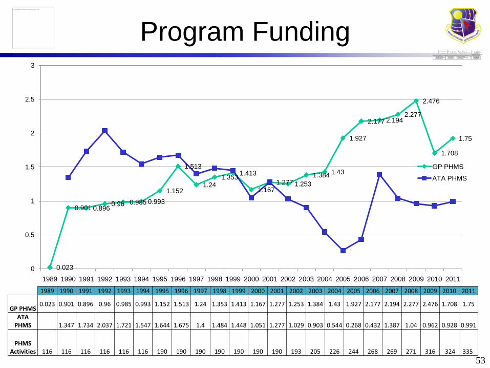
– Approximately $3M/year program ($60M/20
yrs).
– 150 original systems.
– Decisions at initial contract award not to
include J6, ASTF, SL, Hydraulics.
• AEDC PHMS Systems have a
replacement value > $500M (estimate) .
7
Program History at AEDC
8
ETF – B
APTU HPA
PWT Tunnels
ETF – A
Surplus Vessels
ASTF
PHMS
Certification
O&M
ISI-PMs
New PHMS
Fuels
High Pressure Air
???
GN2
Helium - MKI
1950s 1960s 1970s 1980s 1990s 2000s 2010s ???s
PHMS by Definition
• Non-Category D pressure systems
– The design gauge pressure exceeds 150 psi
– The design temperature is less than -20 or
greater than 366°F
– The fluid handled is flammable or toxic
• Any additional system that is deemed to be
mission critical can be included.
• Defined in AEDC Safety and Pressure Design
Standards.
9
Exclusions
– Plumbing, Sewer Systems, Potable Water
Supply Piping.
– Non-Industrial Fire Sprinkler Piping.
– Electrical Conduit.
– Test Articles.
– Facility Heating, Ventilating, and Air
Conditioning.
– Piping of Plastic, Glass, or Any Nonmetallic
Material.
Note: Defined in AEDC Safety and Pressure
Design Standards.
10
Types of Systems Certified by PHMS
11
High Pressure Air
Types of Systems Certified by PHMS
• Gaseous Nitrogen
12
Types of Systems Certified by PHMS
• Liquid Nitrogen
13
Types of Systems Certified by PHMS
• Liquid Oxygen
14
Types of Systems Certified by PHMS
15
JP Fuels
Types of Systems Certified by PHMS
• Steam
16
Types of Systems Certified by PHMS
• Fire Suppression
17
Types of Systems Certified by PHMS
• Gaseous Helium
18
Types of Systems Certified by PHMS
• Butane
19
Types of Systems Certified by PHMS
• Process Air (Wind Tunnel Ducting)
20
Certification Requirements
• A pressure system is certified when inspection, analysis, and testing are performed and documented in accordance with the requirements of AEDC Engineering & Safety Standards.
• Certification of an existing system whose history is not well documented, may be accomplished through reverse engineering/analysis, inspection, and test.
• Existing systems shall be certified as resources become available or when modified.
• Certification documentation for pressure systems, provided in a Certification Report, shall be retained by the support contractor or organization responsible for the pressure system.
21
The Certification Report
• PHMS CERTIFICATION REPORT.
– The Certification Report includes
documentation verifying that a pressure
system was designed, inspected, and
tested in accordance with AEDC-ENGR-
STD-T-2 and is safe for operation at AEDC.
– The Certification Report is broken down
into 8 sections at AEDC.
22
8 Steps to Certification
• Section 1.0
– Project Plan
• This section defines the technical approach
used to certify the piping system.
• This section shall include a description of the
system, existing records, the design and
operating conditions, as well as man-hour
estimates and schedule.
– Non-Destructive Examination (NDE) Plan
• This section contains the initial NDE to confirm
design parameters and identify deficiencies.
• NDE requirements, acceptance criteria, and
supporting tasks are also contained here.
23
8 Steps to Certification
• Kickoff meetings are held with Asset
Owners, System Engineers, and PHMS
Personnel.
24
8 Steps to Certification
• Section 2.0: Config Identification Report
– Collection and review of available
documentation pertaining to the Project.1. System Schematics and Fabrication or Construction
Drawings
2. Device and Component Data
3. Dimensional and As-built Data
4. Piping and Component Material Identification
– System schematic redlined to reflect the
current configuration.
– Device and component ratings verified.
– List of deficiencies found during the
identification effort.
25
Sample of a Redlined Schematic
26
Working
Drawing
Field Walkdown
Identification Report
Drawing
Verification of Field Configuration
27
8 Steps to Certification
• Section 3.0: Evaluation Report– This section shall include calculations performed to
– This section shall include documentation verifying
pressure system relief devices and pressure
gauges have been pressure tested or calibrated for
the intended service.
– Relief device certificates shall specify model
number, serial number, set points, orifice size, flow
capacity verified, and signature of test technician.
– Gauges shall be checked against a calibrated gauge
during system pressure test.
44
8 Steps to Certification
• Section 7.0 In-Service Inspection/Test Plan.• To maintain confidence in the safety of certified
systems, an in-service inspection test program shall be established and executed.
• Inspection is performed as part of the Center’s preventive maintenance program to ensure continued safe, reliable and effective operation as well as to maintain the certification of the PV/S.
• The system specification must be reviewed to ensure it remains accurate and current.
• During walkdown, components or devices must be examined for damage, wear, corrosion, loose, missing parts, etc.
• Any problem and/or discrepancy must be forwarded for resolution.