Page 1
DEPARTMENT OF THE AIR FORCE
Headquarters US Air Force
QTP 4B051-15
24 March 2015Washington, DC 20330-1030
AIR FORCE SPECIALTY CODE 4B051
BIOENVIRONMENTAL ENGINEERING
Electro-Magnetic Frequency (EMF)
QUALIFICATION TRAINING PACKAGE
Accessibility: Publications and forms are available on the e-publishing website at
http://www.e-publishing.af.mil for downloading or ordering.
Realeasability: There are no releasability restrictions on this publication.
Page 2
AFQTP 4B051-15 Journeyman Training Guide: EMF
i
Table of Contents
Line Item 4.9.4.5: Determine EMF Maximum Permissible Exposure (MPEs) limits .......................................................... 1
TRAINER GUIDANCE ........................................................................................................................................................... 1
TASK STEPS ........................................................................................................................................................................... 2
TRAINEE REVIEW QUESTIONS ......................................................................................................................................... 3
PERFORMANCE CHECKLIST.............................................................................................................................................. 4
ANSWERS ............................................................................................................................................................................... 5
Line Item 4.9.4.6: Calculate EMF hazard distances ............................................................................................................... 6
TRAINER GUIDANCE ........................................................................................................................................................... 6
TASK STEPS ........................................................................................................................................................................... 7
TRAINEE REVIEW QUESTIONS ......................................................................................................................................... 9
PERFORMANCE CHECKLIST............................................................................................................................................ 10
ANSWERS ............................................................................................................................................................................. 11
Line Item 4.9.4.7: Perform EMF measurement surveys ...................................................................................................... 12
TRAINER GUIDANCE ......................................................................................................................................................... 12
TASK STEPS ......................................................................................................................................................................... 13
TRAINEE REVIEW QUESTIONS ....................................................................................................................................... 16
PERFORMANCE CHECKLIST............................................................................................................................................ 18
ANSWERS ............................................................................................................................................................................. 19
Line Item 4.9.4.10: Use EMF instrumentation ...................................................................................................................... 20
TRAINER GUIDANCE ......................................................................................................................................................... 20
TASK STEPS ......................................................................................................................................................................... 21
TRAINEE REVIEW QUESTIONS ....................................................................................................................................... 22
PERFORMANCE CHECKLIST............................................................................................................................................ 23
ANSWERS ............................................................................................................................................................................. 24
Line Item 4.9.4.11: Calculate probe burnout ........................................................................................................................ 25
TRAINER GUIDANCE ......................................................................................................................................................... 25
TASK STEPS ......................................................................................................................................................................... 26
TRAINEE REVIEW QUESTIONS ....................................................................................................................................... 27
PERFORMANCE CHECKLIST............................................................................................................................................ 28
ANSWERS ............................................................................................................................................................................. 29
Page 3
AFQTP 4B051-15 Journeyman Training Guide: EMF
1
Line Item 4.9.4.5: Determine EMF Maximum Permissible Exposure (MPEs) limits
TRAINER GUIDANCE
Proficiency Code: 2b
PC Definition: Can do most parts of the task. Needs help only on hardest parts. Can determine step-by-
step procedures for doing the task.
Prerequisites: None
Training References: AFOSH Std 48-9, Electro-Magnetic Frequency (EMF) Radiation Occupational Health
program, 14 Dec 2011
Additional Supporting
References:
AFRL-SA-WP-SR-2013-0003, Base-Level Guide for Electromagnetic Frequency
Radiation, Dec 2012
CDC Reference: 4B051
Training Support Material:
AFOSH Std 48-9, Electro-Magnetic Frequency (EMF) Radiation Occupational Health
program, 14 Dec 2011: Tables A3.1. MPEs for the Upper Tier and A3.2. MPEs for
Lower Tier
Specific Techniques: Conduct hands-on training and evaluation.
Criterion Objective:
Given electro-magnetic frequency (EMF) emitter parameters and listed references,
determine EMF Maximum Permissible Exposure (MPE) limits successfully completing
all checklist items with limited trainer assistance on only the hardest parts.
Notes:
Page 4
AFQTP 4B051-15 Journeyman Training Guide: EMF
2
TASK STEPS
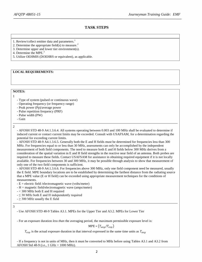
1. Review/collect emitter data and parameters.1
2. Determine the appropriate field(s) to measure.2
3. Determine upper and lower tier environment(s).
4. Determine the MPE.3
5. Utilize OEHMIS (DOEHRS or equivalent), as applicable.
LOCAL REQUIREMENTS:
NOTES:
1
- Type of system (pulsed or continuous wave)
- Operating frequency (or frequency range)
- Peak power (Pp)/average power
- Pulse repetition frequency (PRF)
- Pulse width (PW)
- Gain
2
- AFOSH STD 48-9 A4.1.3.6.4. All systems operating between 0.003 and 100 MHz shall be evaluated to determine if
induced current or contact current limits may be exceeded. Consult with USAFSAM, for a determination regarding the
potential for exceeding current limits.
- AFOSH STD 48-9 A4.1.3.6.5. Generally both the E and H fields must be determined for frequencies less than 300
MHz. For frequencies equal to or less than 30 MHz, assessments can only be accomplished by the independent
measurement of both field components. The need to measure both E and H fields below 300 MHz derives from a
consideration of the spatial variation in E and H field strengths in the reactive near field of an antenna. Both probes are
required to measure these fields. Contact USAFSAM for assistance in obtaining required equipment if it is not locally
available. For frequencies between 30 and 300 MHz, it may be possible through analysis to show that measurement of
only one of the two field components is sufficient.
- AFOSH STD 48-9 A4.1.3.6.6. For frequencies above 300 MHz, only one field component need be measured, usually
the E field. MPE boundary locations are to be established by determining the farthest distance from the radiating source
that a MPE value (E or H field) can be exceeded using appropriate measurement techniques for the conditions of
measurements.
- E = electric field /electromagnetic wave (volts/meter)
- H = magnetic field/electromagnetic wave (amps/meter)
- < 300 MHz both E and H required
- ≤ 30 MHz both E and H independently required
- ≥ 300 MHz usually the E field
3
- Use AFOSH STD 48-9 Tables A3.1. MPEs for the Upper Tier and A3.2. MPEs for Lower Tier
- For an exposure duration less than the averaging period, the maximum permissible exposure level is:
MPE ∗ (𝑇𝑎𝑣𝑔/𝑇𝑒𝑥𝑝)
𝑇𝑒𝑥𝑝 is the actual exposure duration in that interval expressed in the same time units as 𝑇𝑎𝑣𝑔
- If a frequency is not in units of MHz, then it must be converted to MHz before using Tables A3.1 and A3.2 from
AFOSH Std 48-9 (i.e., 1 GHz = 1000 MHz).
Page 5
AFQTP 4B051-15 Journeyman Training Guide: EMF
3
TRAINEE REVIEW QUESTIONS
Line Item 4.9.4.5: Determine EMF Maximum Permissible Exposure (MPEs) limits
1. Into what two categories are EMF MPEs separated?
2. Which EMF environment would describe the exposure for customers at a golf course near an emitter?
3. Using Tables A3.1 and A3.2 in AFOSH Std 48-9, find the MPE for a four minute exposure to an emitter operating in an
upper tier environment at 500 Mhz.
Page 6
AFQTP 4B051-15 Journeyman Training Guide: EMF
4
PERFORMANCE CHECKLIST
Line Item 4.9.4.5: Determine EMF Maximum Permissible Exposure (MPEs) limits
Proficiency Code: 2b
PC Definition: Can do most parts of the task. Needs help only on hardest parts. Can determine step-by-
step procedures for doing the task.
DID THE TRAINEE…
YES NO
1. Review/collect emitter data and parameters?
2. Determine the appropriate field(s) to measure?
3. Determine upper and lower tier environment(s)?
4. Determine the MPE?
5. Utilize OEHMIS (DOEHRS or equivalent), as applicable?
Did the trainee successfully complete the task?
TRAINEE NAME (PRINT) TRAINER NAME (PRINT)
Page 7
AFQTP 4B051-15 Journeyman Training Guide: EMF
5
ANSWERS
1. Into what two categories are EMF MPEs separated?
A: Upper and Lower Tier
(Source: AFOSH Std 48-9, Electro-Magnetic Frequency (EMF) Radiation Occupational Health Program, 14 Dec
2011, p. 10)
2. Which EMF environment would describe the exposure for customers at a golf course near an emitter?
A: Lower Tier
(Source: AFOSH Std 48-9, Electro-Magnetic Frequency (EMF) Radiation Occupational Health program, 14 Dec
2011, p. 10)
3. Using Tables A3.1 and A3.2 in AFOSH Std 48-9, find the MPE for a four minute exposure to an emitter
operating in an upper tier environment at 500 Mhz.
A: MPE (Tavg/Texp)= fM/30 (6 min/4 min) = 500/30 (6/4) = 25 W/m2
(Source: AFOSH Std 48-9, Electro-Magnetic Frequency (EMF) Radiation Occupational Health program, 14 Dec
2011, pp. 25-26)
Page 8
AFQTP 4B051-15 Journeyman Training Guide: EMF
6
Line Item 4.9.4.6: Calculate EMF hazard distances
TRAINER GUIDANCE
Proficiency Code: 2b
PC Definition: Can do most parts of the task. Needs help only on hardest parts. Can determine step-by-
step procedures for doing the task.
Prerequisites: 4.9.4.5 - Determine EMF Maximum Permissible Exposure (MPEs)
Training References:
AFOSH Std 48-9, Electro-Magnetic Frequency (EMF) Radiation Occupational Health
program, 14 Dec 2011
AFRL-SA-WP-SR-2013-0003, Base-Level Guide for Electromagnetic Frequency
Radiation, Dec 2012
Additional Supporting
References:
CDC Reference: 4B051
Training Support Material:
EMF emitter specifications
Paper
Writing utensil
Calculator
AFOSH Std 48-9, Electro-Magnetic Frequency (EMF) Radiation Occupational Health
program, 14 Dec 2011: Tables A3.1. MPEs for the Upper Tier and A3.2. MPEs for
Lower Tier
Specific Techniques: Conduct hands-on training and evaluation.
Criterion Objective:
Given electro-magnetic frequency (EMF) emitter parameters, maximum permissible
exposure (MPE), and listed references, calculate the hazard distance for an EMF emitter,
successfully completing all checklist items with limited trainer assistance on only the
hardest parts.
Notes:
Page 9
AFQTP 4B051-15 Journeyman Training Guide: EMF
7
TASK STEPS
1. Determine MPE. 1
2. Calculate duty factor (DF) and average power (Pavg). 2
3. Calculate absolute gain (Gabs). 3
4. Calculate rotational reduction factor (RRF). 4
5. Calculate hazard distance (Dmpe). 5
6. Utilize OEHMIS (DOEHRS or equivalent), as applicable.
LOCAL REQUIREMENTS:
NOTES:
1. See 4.9.4.5 - Determine EMF Maximum Permissible Exposure (MPEs)
2. The DF represents the emitter’s total “on time”. The Pavg represent the average power output between given the
percentage of “on time”.
The DF for a continuous wave emitter is 1 and the Pavg is the rated power of the emitter.
The DF and Pavg for a pulsed emitter are calculated as: DF = PW * PRF
PW is the pulse width; the length of time, in seconds, that each pulse lasts
PRF is the pulse repetition frequency; the number of pulses that occur in a second
Pavg = Ppeak * DF
3. Gain of an antenna, also called directivity, is the antenna’s ability to concentrate energy in a particular direction
expressed in units of decibels (dB).
Gabs is a unitless number calculated using the gain: Gabs = 10(gain/10)
4. RRF is a unitless number indicating the fraction of time an emitter illuminates a given point.
For stationary emitters, the RRF is 1.
For rotating emitters: RRF = beam width/sector size
beam width is the width of the beam, in degrees
sector size is the size of the total path of the beam, in degrees
Page 10
AFQTP 4B051-15 Journeyman Training Guide: EMF
8
5.
Dmpe = √Pavg ∗ Gabs ∗ RRF
4 ∗ π ∗ MPE
o Dmpe (meters, m)
o Pavg (watts, W)
o Gabs (unitless)
o RRF (unitless)
o MPE (W/m2)
Dmpe can be converted from meters to feet: Dmpe (ft) = Dmpe (m) * 3.28
Page 11
AFQTP 4B051-15 Journeyman Training Guide: EMF
9
TRAINEE REVIEW QUESTIONS
Line Item 4.9.4.6: Calculate EMF hazard distances
Use the following parameters to answer the questions below.
MPE - 10 W/m2
Antenna Gain (Gabs) - 41 dB
Pulse Width (PW) - 0.32 s
Pulse Repetition Frequency (PRF) - 640 pps
Peak Power (Pp) - 250 kW
Beam width - 16
Sector size - 180
1. Calculate the duty factor (DF) and average power (Pavg).
2. Calculate absolute gain (Gabs) and rotational reduction factor (RRF).
3. Calculate the hazard distance.
Page 12
AFQTP 4B051-15 Journeyman Training Guide: EMF
10
PERFORMANCE CHECKLIST
Line Item 4.9.4.6: Calculate EMF hazard distances
Proficiency Code: 2b
PC Definition: Can do most parts of the task. Needs help only on hardest parts. Can determine step-by-
step procedures for doing the task.
DID THE TRAINEE…
YES NO
1. Determine MPE?
2. Calculate duty factor (DF) and average power (Pavg)?
3. Calculate absolute gain (Gabs)?
4. Calculate rotational reduction factor (RRF)?
5. Calculate hazard distance (Dmpe)?
6. Utilize OEHMIS (DOEHRS or equivalent), as applicable?
Did the trainee successfully complete the task?
TRAINEE NAME (PRINT) TRAINER NAME (PRINT)
Page 13
AFQTP 4B051-15 Journeyman Training Guide: EMF
11
ANSWERS
Use the following parameters to answer the questions below.
MPE - 10 W/m2
Antenna Gain (Gabs) - 41 dB
Pulse Width (PW) - 0.32 s
Pulse Repetition Frequency (PRF) - 640 pps
Peak Power (Pp) - 250 kW
Beam width - 16
Sector size - 180
1. Calculate the duty factor (DF) and average power (Pavg).
A:
DF = PW * PRF = 0.32x10⁻⁶
(s) * 640 (pps) = 2.048x10⁻⁴
Pavg = Ppeak * DF = 250 (kW) * 2.048x10-4
= 0.0512 kW
(Source: AFRL-SA-WP-SR-2013-0003, Base-Level Guide for Electromagnetic Frequency Radiation, Dec 2012,
pp. 10-11)
2. Calculate absolute gain (Gabs) and rotational reduction factor (RRF).
A:
Gabs = 10(gain/10) = 10(41/10) = 12,589
RRF = beam width/sector size = 16 / 180 = 0.0889
(Source: AFRL-SA-WP-SR-2013-0003, Base-Level Guide for Electromagnetic Frequency Radiation, Dec 2012,
pp. 15, 88)
3. Calculate the hazard distance.
A:
Dmpe = √Pavg ∗ Gabs ∗ RRF
4 ∗ π ∗ MPE= √
(51.2 W) ∗ (12,589) ∗ (0.0889)
4 ∗ π ∗ 10 W/m2= 21.4 m or 70 ft
(Source: AFRL-SA-WP-SR-2013-0003, Base-Level Guide for Electromagnetic Frequency Radiation, Dec 2012, pp.
87)
Page 14
AFQTP 4B051-15 Journeyman Training Guide: EMF
12
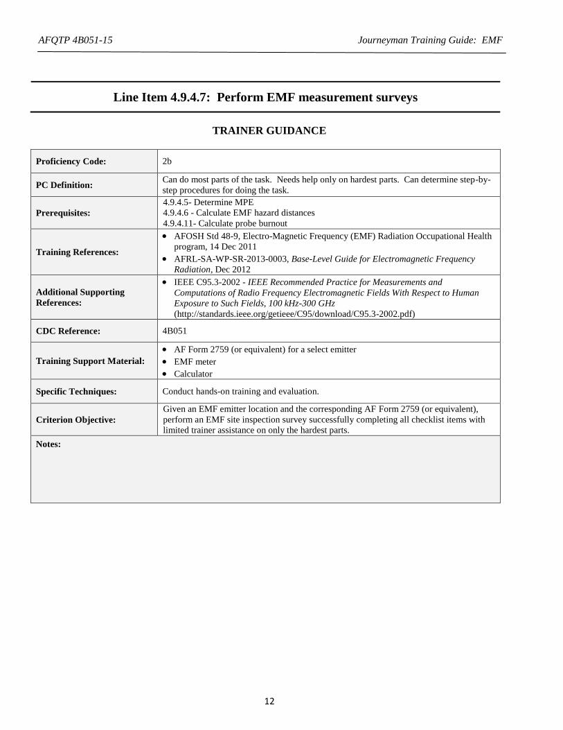
Line Item 4.9.4.7: Perform EMF measurement surveys
TRAINER GUIDANCE
Proficiency Code: 2b
PC Definition: Can do most parts of the task. Needs help only on hardest parts. Can determine step-by-
step procedures for doing the task.
Prerequisites:
4.9.4.5- Determine MPE
4.9.4.6 - Calculate EMF hazard distances
4.9.4.11- Calculate probe burnout
Training References:
AFOSH Std 48-9, Electro-Magnetic Frequency (EMF) Radiation Occupational Health
program, 14 Dec 2011
AFRL-SA-WP-SR-2013-0003, Base-Level Guide for Electromagnetic Frequency
Radiation, Dec 2012
Additional Supporting
References:
IEEE C95.3-2002 - IEEE Recommended Practice for Measurements and
Computations of Radio Frequency Electromagnetic Fields With Respect to Human
Exposure to Such Fields, 100 kHz-300 GHz
(http://standards.ieee.org/getieee/C95/download/C95.3-2002.pdf)
CDC Reference: 4B051
Training Support Material:
AF Form 2759 (or equivalent) for a select emitter
EMF meter
Calculator
Specific Techniques: Conduct hands-on training and evaluation.
Criterion Objective:
Given an EMF emitter location and the corresponding AF Form 2759 (or equivalent),
perform an EMF site inspection survey successfully completing all checklist items with
limited trainer assistance on only the hardest parts.
Notes:
Page 15
AFQTP 4B051-15 Journeyman Training Guide: EMF
13
TASK STEPS
1 Review emitter data and parameters (OEHMIS report, if available). 1
2 Determine emitter hazard potential. 2
3 Coordinate a visit with shop supervision.
4 Select/Inspect survey meter.
4.1 Select the probe that is compatible with the field (E or H) being measured and emitter frequency. 3
4.2 Check calibration date.
4.3 Perform battery/function checks per manufacturer’s instructions.
5 Perform pre-survey calculations.
5.1 Determine the MPE (4.9.4.5) and hazard distance (4.9.4.6).
5.2 Calculate the reading the meter will display at the MPE. 4
5.3 Calculate probe burnout (PDmax) for pulsed emitters. 5 (4.9.4.11)
6 Zero the EMF meter in EMF-free area.
7 Prepare the emitter. 6
8 Provide a complete and proper safety briefing to all personnel involved in the survey
9 Conduct the survey. 7
10 Utilize OEHMIS (DOEHRS or equivalent), as applicable 8
LOCAL REQUIREMENTS:
NOTES:
1.
Before a hazard evaluation can be conducted, potential hazards need to be identified. During the recognition
identification phase each emitter should be reviewed to determine the necessity and priority for performing
further surveys and measurements during the evaluation phase.
o Review past surveys of the emitter or similar systems. Workplace folders, DOEHRS, and the EMF Emitter
Inventory may be able to provide previous survey data.
o Review technical orders on the systems and look for parameters and other hazard distance information.
Use of the EMF Survey Checklist staring on page 68 of AFRL-SA-WP-SR-2013-0003, Base-Level Guide for
Electromagnetic Frequency Radiation, Dec 2012 will help to prevent missing any critical information
2.
Ground level hazard emitters are systems capable of producing power density levels at or above the MPE in
areas accessible to personnel at or near ground level. Many aircraft mounted radar and electronic
countermeasures (ECM) systems will fall into this category.
Climbing hazard emitters are systems capable of producing levels of EMF in excess of the MPE, but only in
areas that require climbing.
Inaccessible emitters are systems capable of producing levels in excess of the MPE, but are not accessible to
personnel.
Short duration emitters are systems capable of producing levels in excess of the MPE, but the transmission
time is relatively short when compared to the MPE averaging time, under normal operating conditions.
Page 16
AFQTP 4B051-15 Journeyman Training Guide: EMF
14
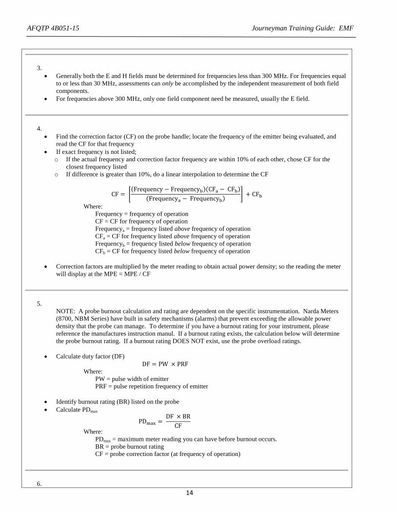
3.
Generally both the E and H fields must be determined for frequencies less than 300 MHz. For frequencies equal
to or less than 30 MHz, assessments can only be accomplished by the independent measurement of both field
components.
For frequencies above 300 MHz, only one field component need be measured, usually the E field.
4.
Find the correction factor (CF) on the probe handle; locate the frequency of the emitter being evaluated, and
read the CF for that frequency
If exact frequency is not listed;
o If the actual frequency and correction factor frequency are within 10% of each other, chose CF for the
closest frequency listed
o If difference is greater than 10%, do a linear interpolation to determine the CF
CF = [(Frequency − Frequencyb)(CFa − CFb)
(Frequencya − Frequencyb)] + CFb
Where:
Frequency = frequency of operation
CF = CF for frequency of operation
Frequencya = frequency listed above frequency of operation
CFa = CF for frequency listed above frequency of operation
Frequencyb = frequency listed below frequency of operation
CFb = CF for frequency listed below frequency of operation
Correction factors are multiplied by the meter reading to obtain actual power density; so the reading the meter
will display at the MPE = MPE / CF
5.
NOTE: A probe burnout calculation and rating are dependent on the specific instrumentation. Narda Meters
(8700, NBM Series) have built in safety mechanisms (alarms) that prevent exceeding the allowable power
density that the probe can manage. To determine if you have a burnout rating for your instrument, please
reference the manufactures instruction manul. If a burnout rating exists, the calculation below will determine
the probe burnout rating. If a burnout rating DOES NOT exist, use the probe overload ratings.
Calculate duty factor (DF)
DF = PW × PRF
Where:
PW = pulse width of emitter
PRF = pulse repetition frequency of emitter
Identify burnout rating (BR) listed on the probe
Calculate PDmax
PDmax = DF × BR
CF
Where:
PDmax = maximum meter reading you can have before burnout occurs.
BR = probe burnout rating
CF = probe correction factor (at frequency of operation)
6.
Page 17
AFQTP 4B051-15 Journeyman Training Guide: EMF
15
Worst case operating parameters should be used to define the location of action level MPEs whenever possible
(fixed position, highest peak power, highest duty factor, and highest gain), unless the system has been
previously measured
Maintain absolute control thru the emitter operator
Ensure that no other interfering EMF sources are being operated in the area
For aircraft mounted radar and electronic countermeasures (ECM) systems
o Ensure aircraft is positioned with ample clear area in front to preclude unnecessary radiation of other objects
o Stop antenna dead ahead in azimuth and at zero degrees or slightly above in elevation, if possible
7.
Visit the site to determine accessibility, locations, and conditions that present potential hazards.
Verify the conclusions drawn during the recognition phase.
To prevent zero drift, connect and turn instrumentation “on” at least 10 minutes before survey measurements are
made to allow the electronics to reach equilibrium.
Measure to identify actual hazard locations and to define controls for these hazards.
Measurements should be conducted to determine two hazard distances, one for the Upper Tier MPE one for the
action level MPE (above the Lower Tier).
Approach the beam from a safe distance (> calculated/theoretical DMPE distance)
Avoid placing any body part or the instrument probe between the feedhorn and the reflector during the survey
Find the beam using the proper probe orientation (out in front and slightly off center)
o If using an isotropic survey meter, probe handle must be parallel with beam
Take small steps forward toward the emitter, periodically stopping to determine the beam size, shape, and
characteristics
Conduct measurements using “spatial averaging” technique
Periodically check the zero of an instrument during survey measurements, especially in one is moving between
areas of significantly different ambient temperatures
Once the meter reaches the reading the meter will display at the MPE, note the location of the probe
Have the operator shut off the emitter
Measure distance from the emitter to the location that the MPE was reached (this will be the actual Dmpe)
Turn on emitter (insure outside actual Dmpe)
Survey the area immediately surrounding the antenna looking for hazardous levels of energy
o Identify reflections, hot spots, side lobes, back scatter etc.
o Check transmission lines
Where multiple EMF emitters may be collocated in fixed arrangements, EMF evaluation data should include a
determination of the weighted contribution from expected simultaneously operated emitters (unity calculation).
8.
The inventories will include at a minimum the following categories: Work Center, Point of Contact (POC), POC
Phone Number, Emitter Nomenclature (i.e. AN/GRT-21), Emitter Description (i.e. TACAN), Quantity,
Frequency Range, Upper Tier and Lower Tier MPEs, and Hazard Distances
Documentation Requirements.
o Include a brief hazard assessment narrative summarizing the potential hazards involved with the use and
operation of the specific emitter.
o The exact locations where the MPEs can be exceeded for both Upper and Lower Tier areas should be
included and demonstrated in a diagram or photograph.
o Facilities responsible for the use and operation of emitters capable of producing levels at or above the MPE
should also have an entry in DOEHRS.
Records of surveys, reports, calculations, and control measures imposed shall be maintained for each fielded
EMF emitter which is capable of exceeding the MPEs in Attachment 3, Table A3.2 of AFOSH Std 48-9
Page 18
AFQTP 4B051-15 Journeyman Training Guide: EMF
16
TRAINEE REVIEW QUESTIONS
Line Item 4.9.4.7: Perform EMF measurement surveys
1. What is the purpose of the hazard distance calculations?
2. What can result from exceeding probe peak power limits during a survey?
3. How should an emitter be configured when performing measurements?
Page 19
AFQTP 4B051-15 Journeyman Training Guide: EMF
17
4. If the meter with the information provided below is reading 17 W/m2
for an emitter operating at a frequency of 933
MHz, what the the true power density?
Frequency Correction Factor
800 0.67
1000 0.81
Page 20
AFQTP 4B051-15 Journeyman Training Guide: EMF
18
PERFORMANCE CHECKLIST
Line Item 4.9.4.7: Perform EMF measurement surveys
Proficiency Code: 2b
PC Definition: Can do most parts of the task. Needs help only on hardest parts. Can determine step-by-
step procedures for doing the task.
DID THE TRAINEE… YES NO
1. Review emitter data and parameters (OEHMIS report, if available)?
2. Determine emitter hazard potential?
3. Coordinate a visit with shop supervision?
4. Select/Inspect survey meter
4.1. Select the probe that is compatible with the field (E or H) being measured and emitter
frequency?
4.2. Check calibration date?
4.3. Perform battery/function checks per manufacturer’s instructions?
5. Perform pre-survey calculations?
5.1. Determine the MPE (4.9.4.5) and hazard distance (4.9.4.6)?
5.2. Calculate the reading the meter will display at the MPE?
5.3. Calculate probe burnout (PDmax) for pulsed emitters?
6. Zero the EMF meter in EMF-free area?
7. Prepare the emitter?
8. Provide a complete and proper safety briefing to all personnel involved in the survey?
9. Conduct the survey?
10. Utilize OEHMIS (DOEHRS or equivalent), as applicable?
Did the trainee successfully complete the task?
TRAINEE NAME (PRINT) TRAINER NAME (PRINT)
Page 21
AFQTP 4B051-15 Journeyman Training Guide: EMF
19
ANSWERS
1. What is the purpose of the hazard distance calculations?
A: To determine the necessity for performing a survey of the emitter and to determine the distance to begin the
survey if needed.
(Source: AFRL-SA-WP-SR-2013-0003, Base-Level Guide for Electromagnetic Frequency Radiation, Dec 2012, pp.
39, 42)
2. What can result from exceeding probe peak power limits during a survey?
A: Probe overload or burnout.
(Source: AFRL-SA-WP-SR-2013-0003, Base-Level Guide for Electromagnetic Frequency Radiation, Dec 2012, p.
46)
3. How should an emitter be configured when performing measurements?
A: Worst case operating parameters under fixed-beam conditions should be used to define the location of action
level MPEs whenever possible.
(Source: AFOSH Std 48-9, Electro-Magnetic Frequency (EMF) Radiation Occupational Health program, 14 Dec
2011, p. 37 and AFRL-SA-WP-SR-2013-0003, Base-Level Guide for Electromagnetic Frequency Radiation, Dec
2012, p. 68)
4. If the meter with the information provided below is reading 17 W/m2 for an emitter operating at a frequency of
933 MHz, what the the true power density?
A:
Frequency Correction
Factor
800 0.67
1000 0.81
CF = [(Frequency − Frequencyb)(CFa − CFb)
(Frequencya − Frequencyb)] + CFb = [
(933 − 800)(0.81 − 0.67)
(1000 − 800)] + 0.67
CF = 0.76
Actual power density = meter reading * CF
= 17 W/m2 * 0.76 = 12.92 W/m
2
(Source: AFRL-SA-WP-SR-2013-0003, Base-Level Guide for Electromagnetic Frequency Radiation, Dec 2012,
p. 46)
Page 22
AFQTP 4B051-15 Journeyman Training Guide: EMF
20
Line Item 4.9.4.10: Use EMF instrumentation
TRAINER GUIDANCE
Proficiency Code: 2b
PC Definition: Can do most parts of the task. Needs help only on hardest parts. Can determine step by step
procedures for doing the task.
Prerequisites: None
Training References:
EMF meter user’s manual
AFRL-SA-WP-SR-2013-0003, Base-Level Guide for Electromagnetic Frequency Radiation
, Dec 2012
AFOSH Std 48-9, EMF Radiation Occupational Health Program
Additional Supporting
References:
CDC Reference: 4B051
Training Support
Material:
EMF meter
EMF meter user’s manual
Specific Techniques: Conduct hands-on training and evaluation.
Criterion Objective: Given an electromagnetic frequency (EMF) meter, properly operate the meter successfully
completing all checklist items with limited trainer assistance on only the hardest parts.
Notes:
Page 23
AFQTP 4B051-15 Journeyman Training Guide: EMF
21
TASK STEPS
1. Identify EMF survey instruments on-hand.
2. Identify and explain functions of meter parts, operating controls and indicators
3. Identify isotropic probes available and explain select probe specifications (to be identified by trainer).
4. Select the appropriate probe (based on emitter specifications provide by trainer).
5. Connect the probe.
6. Prepare the instrument per the user’s manual (i.e., turn on, perform battery check, zero the probe, etc.).
7. Zero the instrument per the user’s manual.1
8. Demonstrate proper probe orientation during use.
9. Take measurements and record the results.
LOCAL REQUIREMENTS:
NOTES:
1. Zero Drift: Zero drift is inherent with instrumentation that utilizes thermocouples and temperature sensitive
components. Premature commencement of a survey without allowing the electronics to reach equilibrium and a change
in ambient temperature during a survey are common causes of zero drift. To reduce errors from zero drift, perform the
following if needed:
Connect and turn instrumentation “on” at least 10 minutes before survey measurements are made. Locate instruments in
the same environment you intend to survey; it doesn’t make much sense to equilibrate instrumentation indoors if one
intends to survey outdoors at a different temperature.
Periodically check the zero of an instrument during survey measurements, especially in one is moving between areas of
significantly different ambient temperatures (sunny vs. shaded). To re-zero instrumentation during a survey one can:
(a) Completely leave the EMF field.
(b) Completely shield the probe in a metal can or Narda instrument case if it provides shielding.
(c) Shield the probe with your body. Your body will effectively absorb signals with frequencies higher than 1,000
MHz.
Page 24
AFQTP 4B051-15 Journeyman Training Guide: EMF
22
TRAINEE REVIEW QUESTIONS
Line Item 4.9.4.10: Use EMF instrumentation
1. How do you reduce zero drift concerns?
Page 25
AFQTP 4B051-15 Journeyman Training Guide: EMF
23
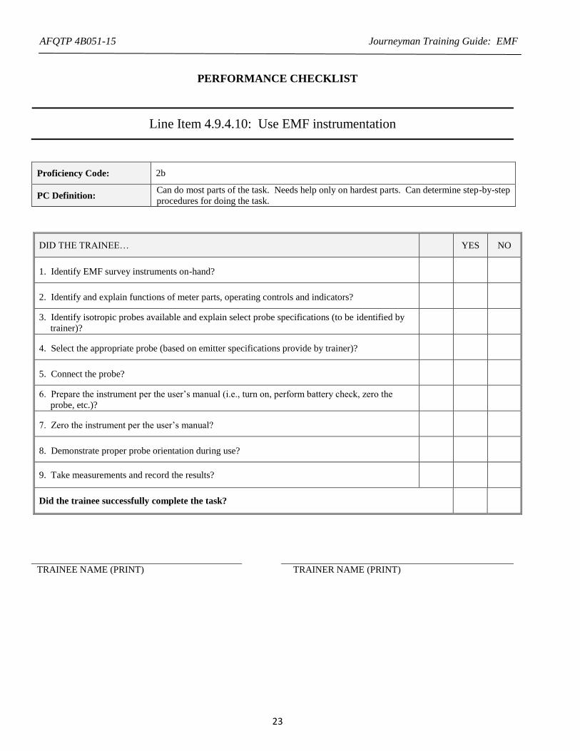
PERFORMANCE CHECKLIST
Line Item 4.9.4.10: Use EMF instrumentation
Proficiency Code: 2b
PC Definition: Can do most parts of the task. Needs help only on hardest parts. Can determine step-by-step
procedures for doing the task.
DID THE TRAINEE… YES NO
1. Identify EMF survey instruments on-hand?
2. Identify and explain functions of meter parts, operating controls and indicators?
3. Identify isotropic probes available and explain select probe specifications (to be identified by
trainer)?
4. Select the appropriate probe (based on emitter specifications provide by trainer)?
5. Connect the probe?
6. Prepare the instrument per the user’s manual (i.e., turn on, perform battery check, zero the
probe, etc.)?
7. Zero the instrument per the user’s manual?
8. Demonstrate proper probe orientation during use?
9. Take measurements and record the results?
Did the trainee successfully complete the task?
TRAINEE NAME (PRINT) TRAINER NAME (PRINT)
Page 26
AFQTP 4B051-15 Journeyman Training Guide: EMF
24
ANSWERS
1. How do you reduce zero drift concerns?
A:
(1) Connect and turn instrumentation “on” at least 10 minutes before survey measurements are made. Locate instruments
in the same environment you intend to survey; it doesn’t make much sense to equilibrate instrumentation indoors if one
intends to survey outdoors at a different temperature.
(2) Periodically check the zero of an instrument during survey measurements, especially in one is moving between areas
of significantly different ambient temperatures (sunny vs. shaded). To re-zero instrumentation during a survey one can:
(a) Completely leave the EMF field.
(b) Completely shield the probe in a metal can or Narda instrument case if it provides shielding.
(c) Shield the probe with your body. Your body will effectively absorb signals with frequencies higher than 1,000
MHz.
(Source: AFRL-SA-WP-SR-2013-0003, Base-Level Guide for Electromagnetic Frequency Radiation, page 48)
Page 27
AFQTP 4B051-15 Journeyman Training Guide: EMF
25
Line Item 4.9.4.11: Calculate probe burnout
TRAINER GUIDANCE
Proficiency Code: 2b
PC Definition: Can do most parts of the task. Needs help only on hardest parts. Can determine step-by-
step procedures for doing the task.
Prerequisites: 4.9.4.5 and 4.9.4.6
Training References:
AFOSH Std 48-9, Electro-Magnetic Frequency (EMF) Radiation Occupational Health
program, 14 Dec 2011
AFRL-SA-WP-SR-2013-0003, Base-Level Guide for Electromagnetic Frequency
Radiation, Dec 2012
Additional Supporting
References:
IEEE C95.3-2002 - IEEE Recommended Practice for Measurements and
Computations of Radio Frequency Electromagnetic Fields With Respect to Human
Exposure to Such Fields, 100 kHz-300 GHz
(http://standards.ieee.org/getieee/C95/download/C95.3-2002.pdf)
CDC Reference: 4B051
Training Support Material: Calculator
Specific Techniques: Conduct hands-on training and evaluation.
Criterion Objective: Given an EMF probe burnout rating, perform a probe burnout calculation successfully
completing all checklist items with limited trainer assistance on only the hardest parts.
Notes:
Page 28
AFQTP 4B051-15 Journeyman Training Guide: EMF
26
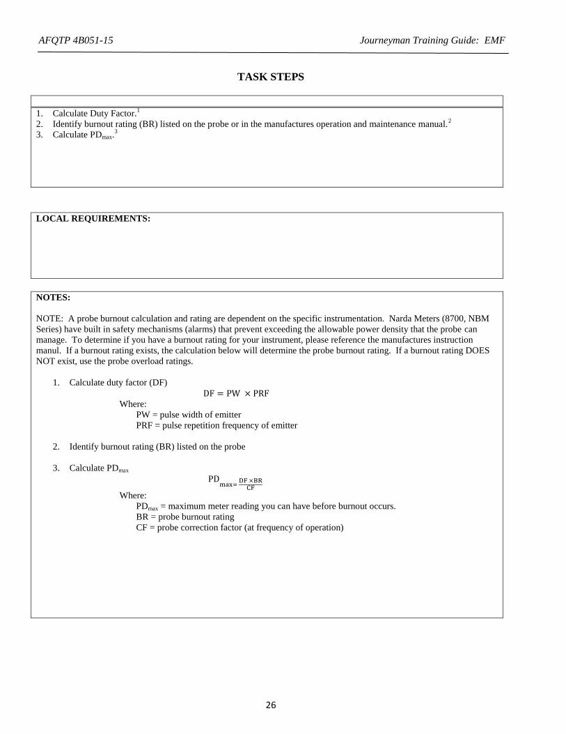
TASK STEPS
1. Calculate Duty Factor.1
2. Identify burnout rating (BR) listed on the probe or in the manufactures operation and maintenance manual.2
3. Calculate PDmax.3
LOCAL REQUIREMENTS:
NOTES:
NOTE: A probe burnout calculation and rating are dependent on the specific instrumentation. Narda Meters (8700, NBM
Series) have built in safety mechanisms (alarms) that prevent exceeding the allowable power density that the probe can
manage. To determine if you have a burnout rating for your instrument, please reference the manufactures instruction
manul. If a burnout rating exists, the calculation below will determine the probe burnout rating. If a burnout rating DOES
NOT exist, use the probe overload ratings.
1. Calculate duty factor (DF)
DF = PW × PRF
Where:
PW = pulse width of emitter
PRF = pulse repetition frequency of emitter
2. Identify burnout rating (BR) listed on the probe
3. Calculate PDmax
PDmax=
DF ×BRCF
Where:
PDmax = maximum meter reading you can have before burnout occurs.
BR = probe burnout rating
CF = probe correction factor (at frequency of operation)
Page 29
AFQTP 4B051-15 Journeyman Training Guide: EMF
27
TRAINEE REVIEW QUESTIONS
Line Item 4.9.4.11: Calculate probe burnout
1. What is the burnout rating for the emitter listed below:
Frequency: 6000 MHz
PW: 2 us
PRF: 360pps
Peak Power: 20 mW
8723D Burnout Rating: 300,000 mW/cm2
Page 30
AFQTP 4B051-15 Journeyman Training Guide: EMF
28
PERFORMANCE CHECKLIST
Line Item 4.9.4.11: Calculate probe burnout
Proficiency Code: 2b
PC Definition: Can do most parts of the task. Needs help only on hardest parts. Can determine step-by-
step procedures for doing the task.
DID THE TRAINEE… YES NO
Calculate Duty Factor?
Identify burnout rating (BR) listed on the probe or in the manufactures operation and
maintenance manual?
Calculate PDmax?
Did the trainee successfully complete the task?
TRAINEE NAME (PRINT) TRAINER NAME (PRINT)
Page 31
AFQTP 4B051-15 Journeyman Training Guide: EMF
29
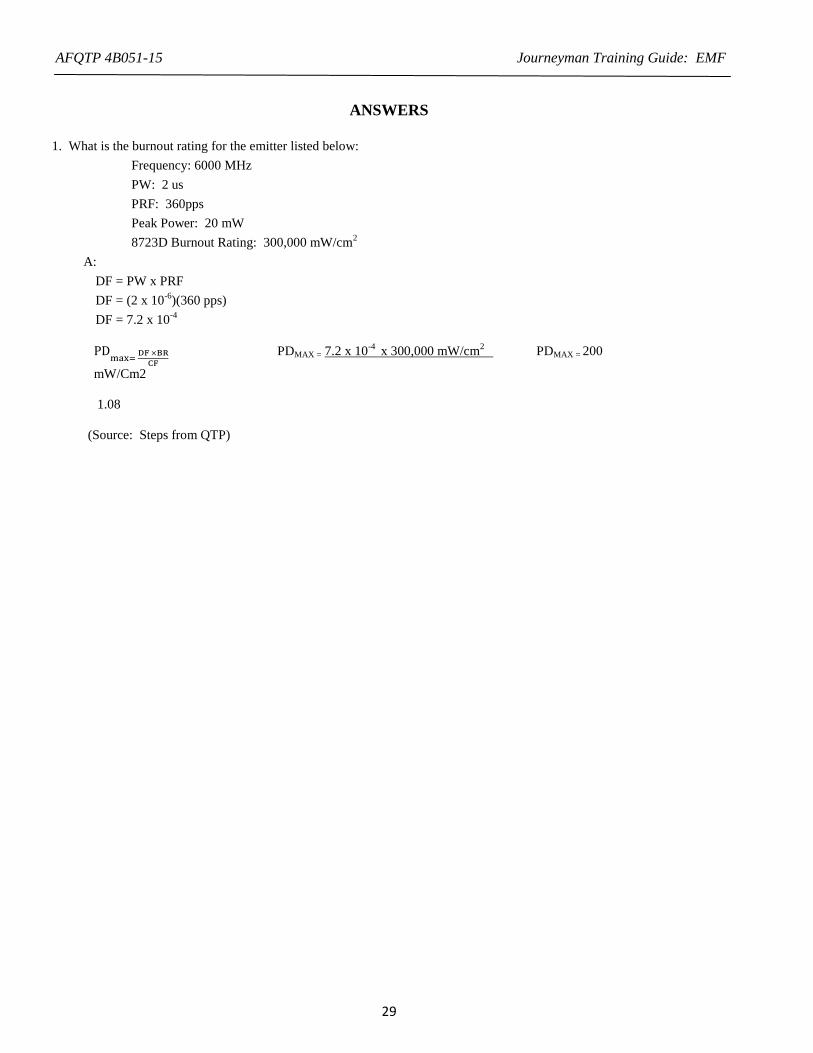
ANSWERS
1. What is the burnout rating for the emitter listed below:
Frequency: 6000 MHz
PW: 2 us
PRF: 360pps
Peak Power: 20 mW
8723D Burnout Rating: 300,000 mW/cm2
A:
DF = PW x PRF
DF = (2 x 10⁻⁶
)(360 pps)
DF = 7.2 x 10⁻⁴
PD
max= DF ×BR
CF PDMAX = 7.2 x 10
-4 x 300,000 mW/cm
2 PDMAX = 200
mW/Cm2
1.08
(Source: Steps from QTP)