56
1 Air Gage Seminar – 1 Air Gaging Basics Willrich Precision Instr. Co Phone: 1-866-WILLRICH (866-945-5742)
1 Air Gage Seminar – 1
Air Gaging Basics
Willrich Precision Instr. CoPhone: 1-866-WILLRICH (866-945-5742)

2 Air Gage Seminar – 2
Air Gage Basics
• Objectives– To provide an understanding of air gage theory
– To learn some of the applications for air gaging
– To understand basic troubleshooting, maintenance and verification procedures

3 Air Gage Seminar – 3
Why Air Gaging?
• Air gaging is a measuring system that– Allows for fast measurement
• Self aligning
– Provides high resolution• Performance to 0.1um/5u”
– Easy to use• Little operator skill involved
– Is non-contact• Won’t mare the part
– Self-Cleaning• Air blows away surface contamination

4 Air Gage Seminar – 4
When to use Air Gaging?
• Have a tight Tolerance condition– <± 40um / ± 0.0015”
• Know when a part is good or bad – Know the variation from the nominal
• Have a high volume of parts to measure– Measure quickly with min operator influence
• Or – have a geometric measurement –– maybe not of high volume but where alternative
measurements (ie CMM’s) are too time consuming• Taper.Straightness/Center Distance
• Environment is dirty

5 Air Gage Seminar – 5
Principles of Air Gaging
D
P
Just like a garden hose –as the distance D gets smaller and restricts the water flow – pressure builds up in the hose. What can you say about the flow of the water as the distance is changed?
Water and air act very similar!

6 Air Gage Seminar – 6
0 Distance + 0 Distance +
PressureFlow
+ +
What’s Happening with Flow and Pressure
Flow increases as the
distance between the
nozzle and restriction
increases
Pressure increases as the distance between the nozzle and
restriction decreases
7 Air Gage Seminar – 7
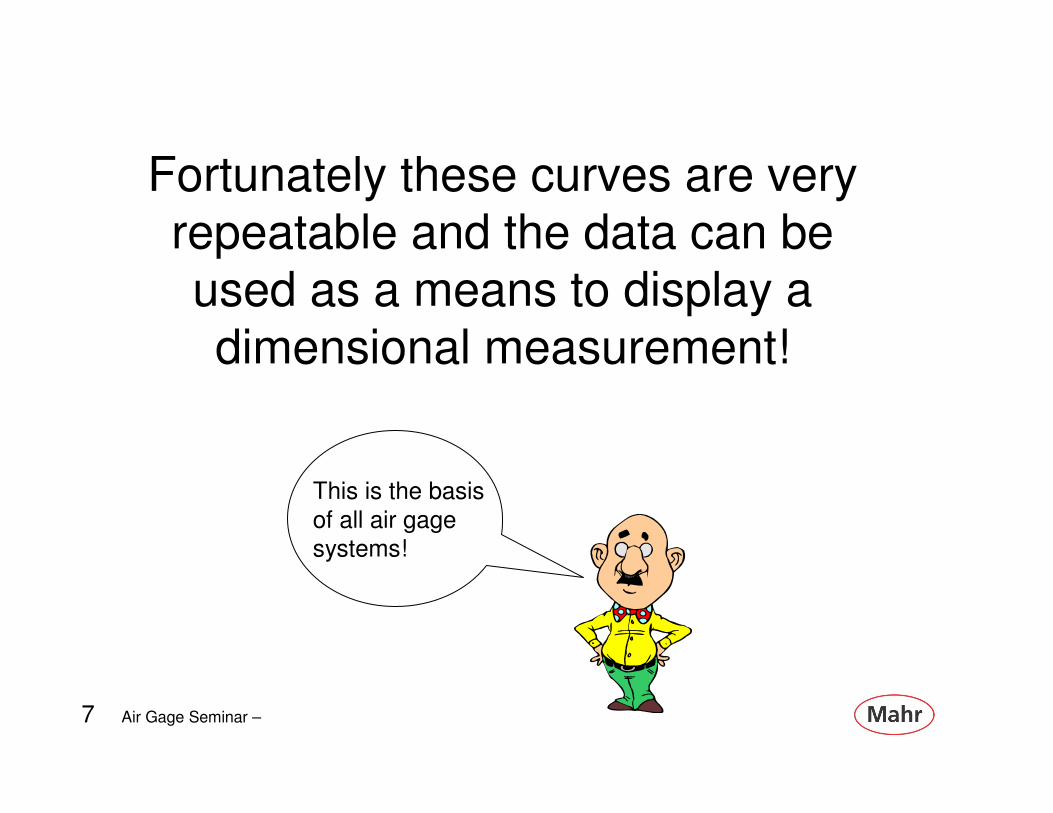
Fortunately these curves are very
repeatable and the data can be
used as a means to display a
dimensional measurement!
This is the basis
of all air gage
systems!

8 Air Gage Seminar – 8
The pressure distance curve are dependent on
the “jet” which the air flows through.
NOZZLE ANNULAR
/ JET VENTING
FEED HOLE
VENT SLOT
An Air Tool holds these nozzles in a precise steel cylinder or ring.

9 Air Gage Seminar – 9
Cross section of Jet
• An air gage works by impeding the flow of air through the jet at a rate which is proportional to the size difference of the dimension being measured
10 Air Gage Seminar – 10
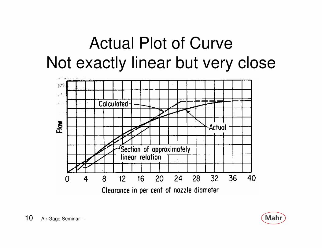
Actual Plot of Curve
Not exactly linear but very close

11 Air Gage Seminar – 11
There are two basic types of Air Gages - Flow and Pressure –with Pressure being the most common
12 Air Gage Seminar – 12
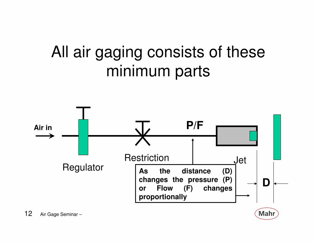
All air gaging consists of these
minimum parts
Air in
RegulatorRestriction Jet
D
P/F
As the distance (D)
changes the pressure (P)
or Flow (F) changes
proportionally

13 Air Gage Seminar – 13
Mahr Federal primarily uses a Balanced Air System
In this system the air is broken into two lines – one acts as a reference and the other does the measuring. This actually measures the difference between the two pressures.

14 Air Gage Seminar – 14
Key factor of a Balanced Air
SystemBecause the balanced system is manufactured to high standards - it is made to place the “zero” point very close to the center of the linear portion of the pressure distance curve. Therefore linearity is known and it requires only one master.

15 Air Gage Seminar – 15
Balanced System Characteristics
• One master very easy set up
• Fixed magnifications – no adjusting
• Accuracy depends on fixed orifices
• Not susceptible to small pressure changes– Excellent stability – readings do not drift after
being set

16 Air Gage Seminar – 16
Balanced System Characteristics
• Good speed of response
• Uses medium/high pressure to clean parts
• Recessed jets - means longer tooling life
– Does not effect magnification
– Can reduce clogging
• If orifices are clogged, magnification can
change

17 Air Gage Seminar – 17
The Air Tooling Clearance
• Clearance allows for getting the part into the gage easily – while minimizing error
• Air Tool clearance - typically .0018” *– As accuracy requires increases - less clearance
and less measuring range
• Centralizing error - increases as air tool clearance increases (typically from wear)
* Plug range will change this

18 Air Gage Seminar – 18
Plug Clearance / Jet Clearance
Jets are recessed for protection and longer plug life

19 Air Gage Seminar – 19
Why is surface finish important?
• The measuring area is fairly
large
• Acts as an
averaging
measurement
• Correlation to
other gaging methods
20 Air Gage Seminar – 20
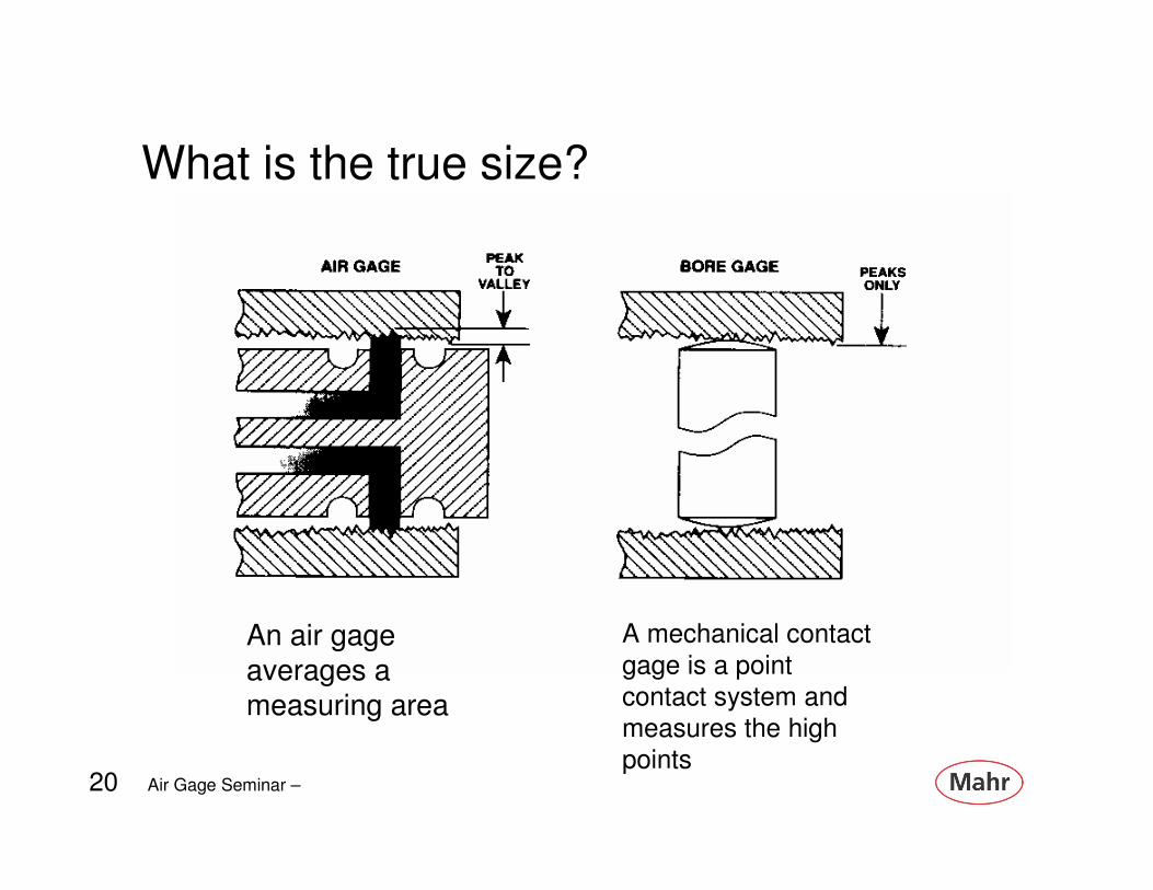
What is the true size?
An air gage averages a measuring area
A mechanical contact
gage is a point
contact system and
measures the high
points
21 Air Gage Seminar – 21
Application – Taper Angle
• Taper is controlled by diameter size and angle.
• Size is controlled by a tolerance – just like an
ID/OD
• Taper can be controlled by three different
methods
– Included angle or angle per side
– Taper per inch or per foot
– Controlling two diameters at specified locations

22 Air Gage Seminar – 22
In all cases air gaging uses
two diameters – at a known distance apart -to perform a
differential measurement –Air tooling is made to
measure these conditions in
one of three ways
Dia. 1
Dia. 2
Distance
23 Air Gage Seminar – 23
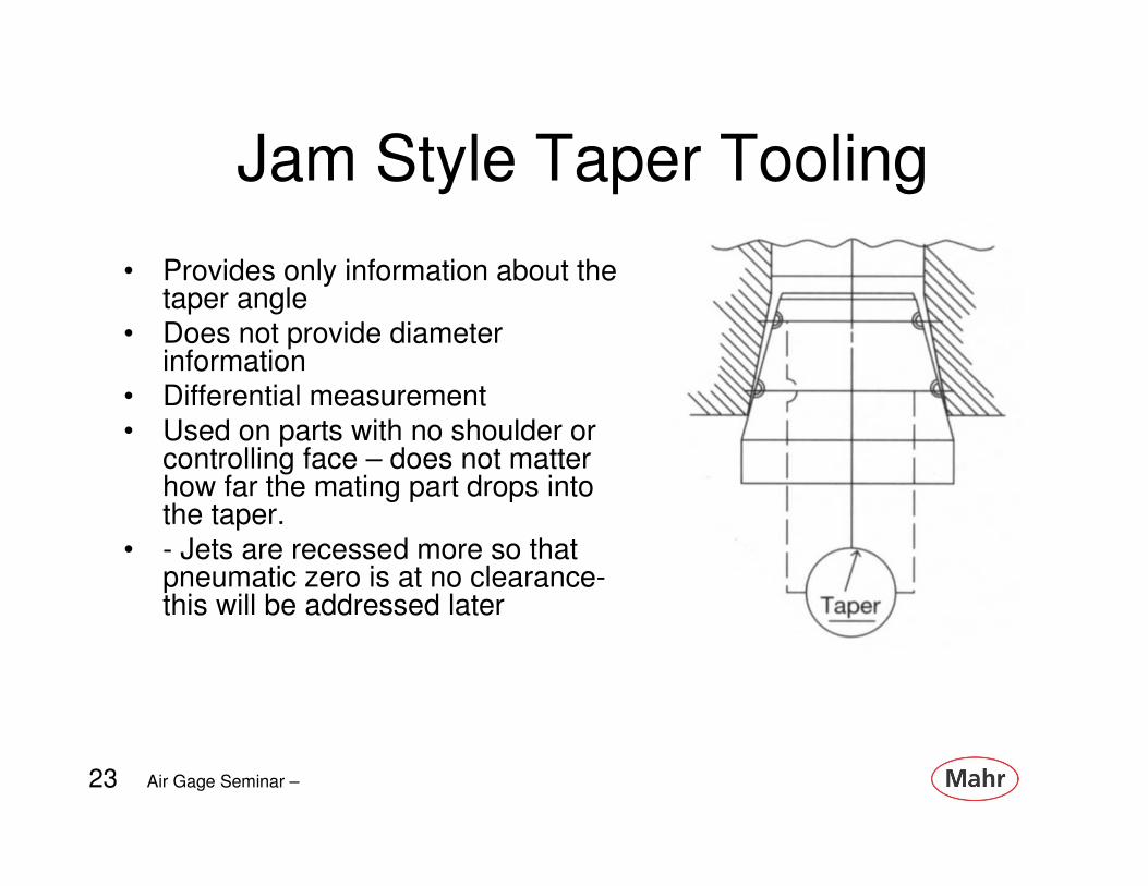
Jam Style Taper Tooling
• Provides only information about the taper angle
• Does not provide diameter information
• Differential measurement• Used on parts with no shoulder or
controlling face – does not matter how far the mating part drops into the taper.
• - Jets are recessed more so that pneumatic zero is at no clearance-this will be addressed later

24 Air Gage Seminar – 24
How a Differential Air Display is
configured

25 Air Gage Seminar – 25
Reading the Differential Taper
Upper set of air jets and lower set of air jets in air ring see the same back pressure. Meter on Dimensionair reads zero
Upper set of jets see more back pressure then lower set. Meter on Dimensionair indicators larger taper angle
Lower set of jets see more back pressure than the upper set of jets. Meter on Dimensionair indicates smaller taper angle
26 Air Gage Seminar – 26
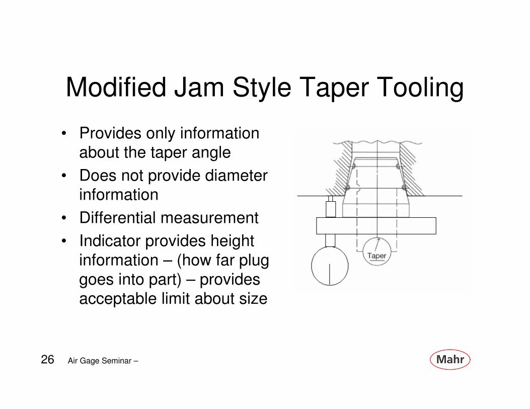
Modified Jam Style Taper Tooling
• Provides only information about the taper angle
• Does not provide diameter information
• Differential measurement
• Indicator provides height
information – (how far plug
goes into part) – provides acceptable limit about size

27 Air Gage Seminar – 27
Clearance Style Taper Tooling
• Provides information about the taper angle
• Provides diameter at two or more locations (potential to
measure straightness)
(bell/mouth/hourglass with a third set of jets)
• Differential measurement of two of more independent
diameters

28 Air Gage Seminar – 28
How an Air Display is configured
to show two diameters and taper

29 Air Gage Seminar – 29
What types of gages does
Stryker employ?
• Two station gage – one for diameter as a location and one for taper only (jam style)
– Uses a diameter and differential display
• Single gage for two diameters and Taper – Clearance style
– Uses three meter display of two diameters
and differential display

30 Air Gage Seminar – 30
Monitoring to achieve good gaging
Excessive plug wear can produce the following conditions:
1. Reduced body diameter increases plug clearance and produces centralizing error.
2. A change in jet diameter or jet orifice size, shape or condition can cause a shift in pneumatic zero.
3. The air flow characteristics of each jet are different causing a balance error.
Therefore to monitor plug wear the above three conditions have to be checked.
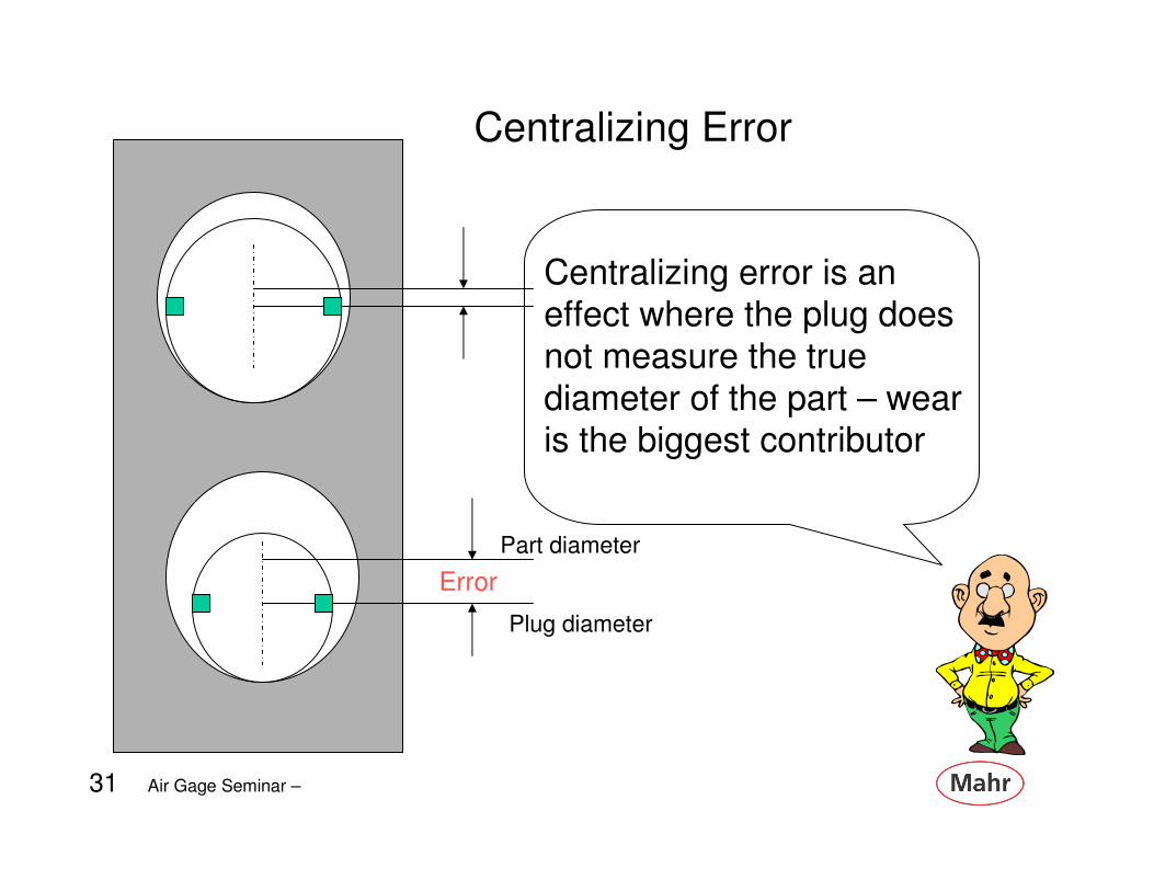
31 Air Gage Seminar – 31
Centralizing error is an effect where the plug does
not measure the true
diameter of the part – wear is the biggest contributor
Part diameter
Plug diameter
Error
Centralizing Error

32 Air Gage Seminar – 32
Monitoring Centralizing error
One method of determining centralizing error is to use an appropriate master [Zero Master]
Mount tooling and master to the Dimensionair, with the jets in a Horizontal position, set meter to “Zero”
Move the master vertically on the plug, note the shift in the readings.
This is the centralization error for this Air Tool and Master.

33 Air Gage Seminar – 33
Monitoring Centralization Error
New tooling is sized to have a clearance that will limit centralizing error to less than one division on the dial.
Centralizing error on used tooling should not exceed 10% of part tolerance.

34 Air Gage Seminar – 34
Because two jets are used to measure diameter –
another form of differential
check – the condition shown will display the same
reading in each case.
Differential Check – Balance Error
35 Air Gage Seminar – 35
Reasons for Balance errors
• Wear – when wear becomes so bad it wears the face of the jet
• Inadvertently pushing in an inserted jet
• Orifice damaged
– During cleaning
– From dirt
– Crack or burr

36 Air Gage Seminar – 36
Monitoring Balance Error
This condition can be checked by using the same method as noted above for centralizing error except position jets in a vertical position and move the master up and down on the plug. Any deviation in readings is balance error. In general, balance error should not exceed 50u”. In no case should total of centralizing plus balance error exceed 10% of part tolerance.

37 Air Gage Seminar – 37
Zero ShiftNew tooling is made to the following pneumatic zero.
Right LeftD-2500 to D-8000 .000l5” .000l5”D-10,000 to D-32,000 anywhere on scale is acceptable
Worn tooling should be monitored to compare tool zero position compared to the zero position on the Dimensionair. This is done by comparing the reading of a zero restrictor with the tooling under test with its certified zero master

38 Air Gage Seminar – 38
Tooling is built to place it’s manufactured zero at the midpoint of the pressure distance curve
Place the zero restrictor, as normally used, on
the front of the Dimensionair or end of hose.
Set zero on Dimensionair by adjusting the zero
setting knob.
Replace the zero restrictor with the air tooling to
be checked and place master on/in the air
tooling so that the jets are at the approximate
mid-point of the master. Without any
adjustment of the zero adjustment knob, the
hand on the Dimensionair should fall within the
limits specified on the following chart.
Monitoring Zero Shift

39 Air Gage Seminar – 39
Acceptable Limit TableDIMENSIONAIR MEASURING SIZE ACCEPTABLE LIMITS
D-2500/D-4000 .123" - .140" Left .0003" Thru Right .0005"D-2500/D-4000 .140" - .185" Left .0005" Thru Right .0005"D-2500/D-4000 .185" - .248" Left .0007" Thru Right .0005"D-2500/D-4000 .248" - UP Left .001” Thru Right .0005"D-5000/D-8000 .123" - .140" Left .00015" Thru Right .0005"D-5000/D-8000 .140" - .185" Left .00025" Thru Right .0005"D-5000/D-8000 .185" - .248" Left .00035" Thru Right .0005"D-5000/D-8000 .248" - UP Left .0005" Thru Right .0005"D-10000/D-16000 .062" - UP Left .0003" Thru Right .0003"D-20000/D-32000 .062" - UP Left .00015" Thru Right .00015"
Excessive reading to right on dial is caused only by contamination and air tooling should be re-cleaned.
Readings to left of acceptable limits indicates potential dial readings beyond the linear portion of the P.D.C. and air tooling should be reworked or replaced.

40 Air Gage Seminar – 40
Inspecting Jam Style Tooling
• Jam style tooling does not have the normal clearance built into it
– The jets are recessed more to place
pneumatic zero at interference location
– Therefore centralizing error or balance test
are not applicable
– Zero Shift test is used to inspect for wear
or balance error
41 Air Gage Seminar – 41
Testing for Zero on Jam tooling
Required – the appropriate restrictor kit with two
zero masters
– Place a zero restrictor on each of the channels on
the differential Dimensionair and adjust the unit to “zero”
– Replace one of the restrictors with a channel from the air tooling – monitor zero position and
compare to chart
– Repeat using the second channel and monitor
zero position and compare to chart
42 Air Gage Seminar – 42
Inspecting Masters
It’s possible to use qualified gages to compare Reference masters to Workingmasters
– Use Reference master to verify gage and
set to pneumatic zero
– Replace with working master
– Note difference – and compare to your
acceptable limit – 10% part tol?

43 Air Gage Seminar – 43
Using Master Deviation
• Although the goal is to make a perfect zero master –no manufacturing techniques are capable of doing this
• Techniques are available that can allow the measurement of masters to very high accuracies– For example – a diameter reading on a master may have a
deviation of + 25u” (the master is 25u” larger then the nominal zero size)
• Using the Masters known error can improve the results from the gaging system
• It also can lower the cost of purchasing masters
44 Air Gage Seminar – 44
How to Set-up gages using the
Master Deviation• Using previous example – cert shows a +25u” deviation
on diameter. Using a .500” nominal size – master is actually .500025”
• Accepted procedure – place master in the gage and mechanically adjust gage dial to read zero– This shifts the display to read a part 25u” larger then it actually is
– Often used when the master deviation is less then 10% of part tolerance
• Better procedure – place the master in the gage and mechanically adjust gage dial to read +25u”– This makes the gage read the true master value as the proper
displayed size – and makes the parts read their actual size

45 Air Gage Seminar – 45
Other topics
46 Air Gage Seminar – 46
Mahr Federal’s Primary air system is based on the Balanced Pressure circuit
• In this system we know that by controlling the pressures, jet diameters, and jet recesses, a very repeatable and accurate measurement system can be created. The accuracy is buiilt into the tooling and readout
• The data can be used as a means of displaying a dimensional measurement!

47 Air Gage Seminar – 47
OR

48 Air Gage Seminar – 48
With and Adjustable Magnification system
• By varying the pressure to change the system magnification to match up with the gage limits, a
repeatable measurement system can be created.
The data can be used as a means of displaying a
dimensional measurement!

49 Air Gage Seminar – 49
Back Pressure Bleed System
50 Air Gage Seminar – 50
Back Pressure Bleed System
• Very versatile
– Accepts almost any manufacturer’s tooling
• Fixed regulator controls air pressure for
maximum linearity
• Adjustable restrictor changes the
magnification for different tooling
• Adjustable bleed changes zero location

51 Air Gage Seminar – 51
Back Pressure Bleed System
• Has two controls for set up – zero & span• Two masters for calibration and traceability
• Adjustable magnification can compensate for worn tooling
• Capable of accommodating jet sizes from 0.020” thru 0.093”
• Has the potential of setting the gage out side of the linear portion of the measuring range
• Additional masters add to cost and maintenance• In mechanical systems set up can be difficult and
time consuming
52 Air Gage Seminar – 52
How do Electronic columns work
with Single of Two masters?
53 Air Gage Seminar – 53
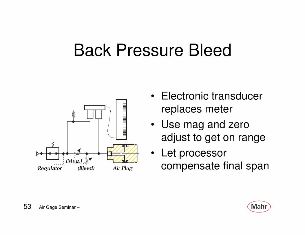
Back Pressure Bleed
• Electronic transducer
replaces meter
• Use mag and zero
adjust to get on range
• Let processor
compensate final span

54 Air Gage Seminar – 54
Differential
• Electronic transducer
replaces meter
• Transducer has
enough measuring
range to handle wide
range of tooling
• Let processor
compensate final
span

55 Air Gage Seminar – 55
Which is the best?
• All have good and bad points
• When used in normal operating conditions
and supplied by “reputable” manufacturers,
good results can be obtained
• Consider
– Ease of set up
– Value
– Support

56 Air Gage Seminar – 56
Single Master System Dual Master System
Errors at extremes of tolerance
Errors at center of tolerance
The type of air gage selected – determines where the error can be


