29 AIR HANDLING SYSTEM OPTIMISATION Often each floor of a building has an air handling system consisting of a plant room, ducting and equipment such as fans and heaters. The cost of the system consists of the capital cost of the equipment and the operat- ing cost to satisfy the thermal loads. An efficient method is required for evaluating the operating costs when the configuration of the system is spec- ified and the thermal loads are known. The operating cost of a particular configuration are obtained by solving a nonlinear program. The method is efficient since it consists of solving a sequence of single period models. 1. Introd uction This problem was presented to the 1991 Mathematics-in-Industry Study Group at the University of South Australia by Kinhill Spence. The problem is concerned with the air conditioning of buildings. The decisions which need to be investigated are the configuration of the ducting for a floor of the building and the optimal configuration of secondary devices in each zone. Presently a computer package called BUNYIP is used to evaluate the operating cost for a particular configuration of air handling equipment. An alternative method is required which speeds up the evaluation. A typical air handling system is sketched in Figure 1. A fan forces a mixture of fresh air and recirculated air through primary heating and cooling coils. Then the air passes along a duct to a zone on the floor of the building. Each zone may have secondary devices which reduce the volume of air, mix the air with heated air in the ceiling, or reheat the air. There is no provision in the zones for cooling of the air. The air from the zones returns to the fan via the ceiling cavity, where additional heating of the air takes place. In the normal design process there are a large number of possible configura- tions of ducting which link the zones to the primary air handling plant. For each configuration there are many possible ways of configuring the secondary devices. Kinhill Spence is therefore interested in methods which efficiently compare alternative air handling configurations. They are prepared to specify the thermal loads in each zone during each time period. They require an efficient method of calculating the operating cost of the configuration for specified thermal loads. Heat transfer into a zone is defined as a positive heat transfer, while heat transfer out of a zone is defined as a negative heat transfer. The zone with the
Transcript
29
AIR HANDLING SYSTEM OPTIMISATION
Often each floor of a building has an air handling system consisting of aplant room, ducting and equipment such as fans and heaters. The cost ofthe system consists of the capital cost of the equipment and the operat-ing cost to satisfy the thermal loads. An efficient method is required forevaluating the operating costs when the configuration of the system is spec-ified and the thermal loads are known. The operating cost of a particularconfiguration are obtained by solving a nonlinear program. The method isefficient since it consists of solving a sequence of single period models.
1. Introd uct ion
This problem was presented to the 1991 Mathematics-in-Industry StudyGroup at the University of South Australia by Kinhill Spence. The problemis concerned with the air conditioning of buildings. The decisions which need tobe investigated are the configuration of the ducting for a floor of the buildingand the optimal configuration of secondary devices in each zone. Presently acomputer package called BUNYIP is used to evaluate the operating cost for aparticular configuration of air handling equipment. An alternative method isrequired which speeds up the evaluation.
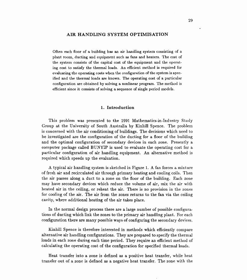
A typical air handling system is sketched in Figure 1. A fan forces a mixtureof fresh air and recirculated air through primary heating and cooling coils. Thenthe air passes along a duct to a zone on the floor of the building. Each zonemay have secondary devices which reduce the volume of air, mix the air withheated air in the ceiling, or reheat the air. There is no provision in the zonesfor cooling of the air. The air from the zones returns to the fan via the ceilingcavity, where additional heating of the air takes place.
In the normal design process there are a large number of possible configura-tions of ducting which link the zones to the primary air handling plant. For eachconfiguration there are many possible ways of configuring the secondary devices.
Kinhill Spence is therefore interested in methods which efficiently comparealternative air handling configurations. They are prepared to specify the thermalloads in each zone during each time period. They require an efficient method ofcalculating the operating cost of the configuration for specified thermal loads.
Heat transfer into a zone is defined as a positive heat transfer, while heattransfer out of a zone is defined as a negative heat transfer. The zone with the
30 Kinhill Spence Pty Ltd
TmVAV 1
TTreheat
t; Tor-t' ---.:... zone 1
r-+ V!(l)
~ VAV2 -- reheat zone 2
V!(2)
r-+ VAV3 zone 3
V!(3)i;
heat
return air to VAV's Teo•
excoils 3 -Vm(3)
Tlo Tin frecoils 12 fan
V12 VI
n
haust-sh--
Figure 1: Configuration of an air handling system.
highest thermal load controls the air flow in the duct so as to keep the zone atits upper temperature limit for comfort. Other zones on the duct also receiveair which is controlled by this zone.
If the supply air to a non-controlling zone receives air which produces atemperature below its lower temperature limit of comfort, then several actionscan take place. The volumetric flow rate of air into the zone may be reduced byusing a variable air volume (VAV) box. If the air reaches its minimum allowedvolumetric flow rate without the temperature reaching the comfort range, thenthe air may be mixed with return air from the ceiling space. If the temperaturein the zone is still below the lower limit, a reheat device is used to heat the air.Generally the priority order for introducing secondary devices is VAV, VAV withreturn air, and finally reheat.
A thorough examination of the design process involves time dependent heatflows and humidity effects. A full treatment of all these effects was impossibleduring the Study Group. The crucial issue for the mathematicians was to de-velop an efficient method of comparing alternative configurations of ducting and
Air handling system optimisation 31
secondary devices. A good way to investigate the problem was to look at steadystate conditions without humidity effects for a specified scenario of thermal loadsand ambient temperatures.
Given an air handling configuration and the load profile over a whole year,the objective is to find the operating cost. This report shows that mathemati-cal programming methods can efficiently compare various configurations of airhandling equipment. The input to the model is a sequence of thermal loads andambient temperatures. The output is the operating conditions and operatingcost in each period.
Section 2 discusses the process of designing the air handling equipment for afloor of a building. The types of equipment are listed and their function is dis-cussed. Section 3 develops a mathematical model of the air handling equipment.The notation is introduced and a formulation is given of the air handling prob-lem. The method of solving the model is discussed. Section 4 uses a numericalexample which illustrates the air handling model. Mathematical programmingmethods are used to determine controls and flows. Section 5 discusses the resultsdiscovered by the experiments shown in Section 4.
2. Background
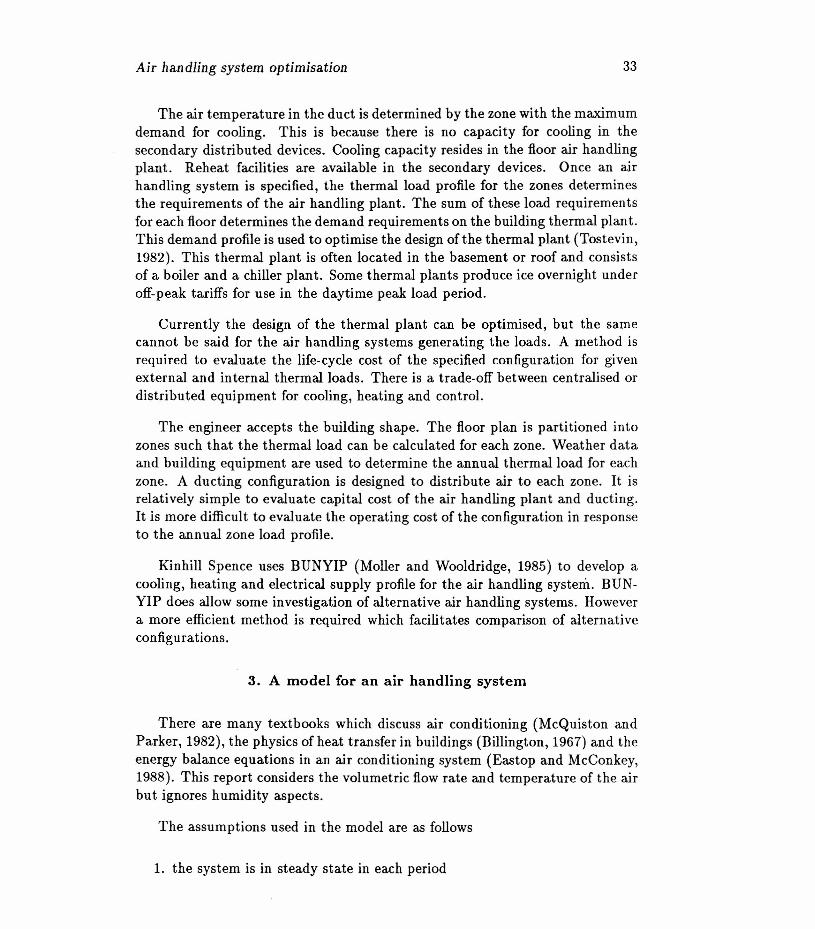
Figure 2 illustrates the processes involved in the design of an air conditioningsystem for a building. The architect designs the shape ofthe building on the basisof functional requirements and the constraints of the allotment. Generally eachfloor of the building has an air handling plant consisting of fresh air intake, fan,and cooling and heating coils. Ducting and flexible tubes are used to distributeair. The ceiling cavity is used for return flow to the plant.
Each floor is divided into a number of separate zones on the basis of thethermal loads. The exterior of the building is referred to as the skin. The regionwithin 4 metres of the skin forms the perimeter zones. Often these zones consistof individual offices with window outlooks. The remainder of the floor area formsan internal zone. Often this zone is used for open plan activities.
Each zone has an annual thermal load profile which is determined from fac-tors external to the building such as expected weather conditions and internalfactors such as occupancy and lighting. It may be possible to characterise theload profile using peak and marginal days in each of summer, mid-season andwinter. Because the system is designed for peak loading it is often found thatproblems occur in mid-season. There may be a large variation in thermal loadsbetween zones served by the same duct.
32 Kinhill Spence Pty Ltd
design shape of building
1zone the floor plan
1weather - determine annual thermal f--
occupancyconditions load profile for each zone lighting
1temperature -optimise air handling system f-- air flowconstraints requirements
1optimise thermal plant
Figure 2: Processes involved in the design of an air-conditioning system.
Room comfort is measured by temperature and air flow. The typical tem-perature range is 20°C to 25°C and the minimum air flow rate of 5 litres persecond per square metre. A minimum fresh air requirement is 5 litres per secondper person. The percentage of fresh air may be as high as 100% if the ambientconditions are suitable. We assume a floor plan with ducting in the ceiling forcooling and heating.
Primary air handling equipment provides conditioned air to each zone. Theair handling equipment supplies cooling and heating to satisfy the thermal loadin each zone within a comfort tolerance for temperature and air flow. There arean enormous number of possible configurations of air handling equipment whichwill satisfy the load profile for each zone. A configuration with separate ductingto each zone has a high capital cost and low operating cost. A configuration withone line of ducting, variable volume boxes, and reheat coils has a low capitalcost and high operating cost.
A VAV box uses adjustable dampers to control the flow of air through thebox. Each diffuser maintains its proportion of the air flow as the volume changes.A fan assisted VAVbox is able to mix return air with air from the duct to changethe temperature of the air in the box. Heaters are used to reheat air from theduct that is too cold.
Air handling system optimisation 33
The air temperature in the duct is determined by the zone with the maximumdemand for cooling. This is because there is no capacity for cooling in thesecondary distributed devices. Cooling capacity resides in the floor air handlingplant. Reheat facilities are available in the secondary devices. Once an airhandling system is specified, the thermal load profile for the zones determinesthe requirements of the air handling plant. The sum of these load requirementsfor each floor determines the demand requirements on the building thermal plant.This demand profile is used to optimise the design of the thermal plant (Tostevin,1982). This thermal plant is often located in the basement or roof and consistsof a boiler and a chiller plant. Some thermal plants produce ice overnight underoff-peak tariffs for use in the daytime peak load period.
Currently the design of the thermal plant can be optimised, but the samecannot be said for the air handling systems generating the loads. A method isrequired to evaluate the life-cycle cost of the specified configuration for givenexternal and internal thermal loads. There is a trade-off between centralised ordistributed equipment for cooling, heating and control.
The engineer accepts the building shape. The floor plan is partitioned intozones such that the thermal load can be calculated for each zone. Weather dataand building equipment are used to determine the annual thermal load for eachzone. A ducting configuration is designed to distribute air to each zone. It isrelatively simple to evaluate capital cost of the air handling plant and ducting.It is more difficult to evaluate the operating cost of the configuration in responseto the annual zone load profile.
Kinhill Spence uses BUNYIP (Moller and Wooldridge, 1985) to develop acooling, heating and electrical supply profile for the air handling system. BUN-VIP does allow some investigation of alternative air handling systems. Howevera more efficient method is required which facilitates comparison of alternativeconfigurations.
3. A model for an air handling system
There are many textbooks which discuss air conditioning (McQuiston andParker, 1982), the physics of heat transfer in buildings (Billington, 1967) and theenergy balance equations in an air conditioning system (Eastop and McConkey,1988). This report considers the volumetric flow rate and temperature of the airbut ignores humidity aspects.
The assumptions used in the model are as follows
1. the system is in steady state in each period
34 Kinhill Spence Pty Ltd
2. there are no storage effects between periods
3. each zone is independent of the other zones
4. for each primary zone in the central plant, either the heater or the cooleris used, but not both in a period
5. the effects of humidity are ignored in the analysis
6. there is a requirement that a proportion, 0:, of the re circulating air be freshair
Consider the air handling system for a floor of a building as a plant, ductingand secondary control devices. The plant consists of a fan and primary heatingand cooling coils.
Suppose there are n zones in the building which are indexed by j = 1, ... , n.In zone j at time i the temperature is denoted by T( i, j), the air volumetric flowrate by V(i,j), and the thermal load by the heat transfer rate Q(i,j). The SIunits are Kelvin, litres/a, and Watts respectively.
The following notation is used to denote the constants in the air handlingsystem.
Q(i,j)Ta(i)
thermal load in a zone (kW)ambient temperature in a period (OC)specific heat (J /litre DC)heat input in the ceiling (kW)minimum volume flux of fresh air (litre/a)cost of operating the fan ($/(litre/s))cost of operating the heater ($/kWH)cost of operating the cooler ($/kWH)cost of operating secondary reheat ($/kWH)
The following notation is used to denote the variables in the air handlingsystem.
temperature at inlet to secondary device (OC)temperature of return air to secondary device (OC)temperature at inlet to zone (OC)temperature at outlet to zone (OC)temperature at inlet to ceiling (OC)temperature at outlet to ceilingfrC)temperature at inlet to fan (OC)temperature at outlet to fan (OC)volume flux at inlet to secondary device (litre/s)volume flux of return air to secondary device (Iitre/s)heat input to secondary device (kW)heat input to primary coils (kW)primary cooling (kW)proportion of fresh airtotal operating cost ($)
The input data is the thermal load in each zone, the ceiling heat load, thefresh air ambient temperature and the costs of energy.
The equation governing the energy flow balance is
(1)
where Q is the heat transfer (kW), M is the mass flow rate (kg/s), C is the specificheat of the air (kJ /kg QC), and tlT = To - Tn is the temperature difference (OC)between the outlet and inlet of the zone.
The energy flow balance can be expressed in terms of the volumetric flowrate of moist air as
Q = V sh(To - Tn) (2)where V is the volumetric flow rate (Iitre/s] and Sh is the sensible heat of themoist air (kJ /litre QC). The sensible heat is the ratio of the specific heat of moistair to the specific volume of moist air at 21°C and 50% relative humidity. Itsvalue is 0.001213 kJ /litre QC.
If a range of temperature is specified at the room outlet, then there are manyfeasible solutions. The optimal solution is determined by the following nonlinearprogramming problem:
min Z = cf Vf + ch(H(12) + H(3)) + ce(C(12) + C(3)) + Cc L S(j) (3)j
The dependence on the index i is suppressed because the time periods are in-dependent when calculating operating costs. Operating costs and heat inputsfrom VAV fans are ignored.
Equation (3) is the total operating cost of the fan, heating coils, cooling coilsand reheat devices. The left hand side of equation (4) is the heat generated bythe primary fan, and is a polynomial function of Vf' For simplicity we have usedonly the linear term. Equations (4) to (9) are energy flow balance equations forthe fan, primary heating and cooling coils, secondary reheat devices, zones andceiling. Equations (10) to (13) relate the volume flow rates, while equations (14)to (15) relate the mixing of the air at different temperatures. Equations (16) to(17) relate to the addition of fresh air to the system.
We used GAMS software (Brooke, Kendrick and Meeraus, 1988) to inves-tigate this model on a PC. Tolerances and options were left at their defaultsettings.
4. Results of a test problem
The input data includes the thermal load in the zone and the fresh air am-bient temperature as a function of time. Table 1 shows the data used in thesimple illustrative example with two time periods.
The time independent input data is the ceiling heat load, the minimum
volumetric flow rate and the energy costs. Table 2 shows the data used in theexample.
Table 2: Constants for the simple model
Sh 1.213E-3G 1.00
~ 50Ch 0.03Cc 0.04Ce 0.11cJ 1.65E-4
The operating cost was determined for three configurations of the exampleproblem. The first configuration had a variable speed fan and secondary reheatdevices in zones 1 and 2. The results for this configuration are given in columns2 and 3 of Table 3. Output temperatures in each zone are at their limits andthe secondary reheat device is used in zone 1 during period 2. The operatingcost for two periods (hours) is $0.94.
The second configuration has a fixed speed fan and secondary reheat facilitiesin zones 1 and 2. The results are given in columns 4 and 5 of Table 3. The air flowrate is at its maximum in each zone for each period and the outlet temperaturesare at their limits. The secondary reheat device supplies heat to the coolerof zones 1 and 2. The operating cost for two periods is $1.13. Although theoperating cost for the fix speed fan is more than that of the variable speedfan, it is the cheaper solution when the capital cost of the variable speed fan isincluded.
The third configuration has a variable speed fan, return air to a VAV box ineach zone and reheat devices in zones 1 and 2. In addition the outlet temperatureat the primary cooling coils is constrained to greater than 13°C. The results givenin columns 6 and 7 of Table 3 show that significant return air is used for heating
38 Kinhill Spence Pty Ltd
and the operating cost is $0.88.
19.5 ~l.O 28.2 20.0- VAV 1 ~ reheat zone 1
r--- IJO19.5 ~9.5 19.5 25.0- VAV2 f---. reheat zone 2
to28.4 ~5.5 20.0r--- VAV 3 zone 3
IJO 2l.
heat
300 22.I
excoils 3 -
150
19.5 18.5 frecoils 12 fan
450 600
7
6haust-sh
Figure 3: Results for the third configuration during the second period where val-ues with a decimal point are temperatures (OC) and other values are volumetricflow rates (Iitres/s].
5. Discussion
The model given in Section 3 requires only the specification of the thermalloads and the ambient temperatures for each period. Very little time is requiredfor the data preparation stage.
The results shown in Section 4 indicate that the warmest zone on a commonduct is at its upper temperature limit in every period. For the variable speedexample, zone 1 is warmer than zone 2 in period 1 and its outlet temperature is25°C, while zone 2 is warmer than zone 1 in period 2 and its outlet temperatureis 25°C.
Good initial values for the variables reduce the computation time of theprogram. There are a number of ways for developing a good starting point.
Air handling system optimisation 39
The initial values can be made conditional on the thermal loads and ambienttemperature for the. period and the zone. An alternative method is to startfrom the optimal solution of a problem with similar thermal loads and ambienttemperatures.
Table 3: Optimal values for the variables for the simple model
a 0.116 0.386 0.100 0.323 0.100 0.323Cost 0.94 1.13 0.88
For a given configuration the calculations can be performed sequentially intime with the optimal solution of one period becoming the starting point forthe next period. After the calculations for the final period are finished, thecapital cost of the equipment can be included on the basis of the maximumvalue attained by the equipment.
40 Kinhill Spence Pty Ltd
The preliminary results indicate the model can determine the operating costof a variety of secondary devices. The model compares the cost of various con-figurations of secondary devices for a particular configuration of ducting.
The model can be reformulated to include capital costs. This requires theintroduction of binary integer variables and results in a mixed integer nonlinearprogram. Such models can be solved by decomposition methods (Benders, 1962).
Further work is require to model other configurations such as a constantvolume 'skin' conditioners with a VAV serving other zones. It may be possibleto evaluate such a configuration by fixing the value of a flow volume variable ata constant value.
Acknowledgements
The moderator for this problem (Graham Mills) would like to acknowledgethe assistance of the Kinhill Spence representative, Greg Croft, and the contri-butions of Basil Benjamin, Greg Oldman and Peter Pudney.
N.S Billington, Building Physics: Heat (Pergamon Press, 1967).
A. Brooke, D. Kendrick & A. Meeraus, GAMS: A User's Guide (The ScientificPress, Redwood City, CA, 1988).
T.D. Eastop & A. McConkey, Applied thermodynamics for engineering technol-ogists 4th Ed. (Longmans, 1988).
S.K. Moller & M.J. Wooldridge, User's Guide for the computer program Bunyip:Building energy investigation Package (Version 2.0) CSIRO Division ofEnergy Technology, Technical Report - TR6, Highett, Victoria, 1985.
F.C. McQuiston & J.D. Parker, Heating, ventilating and air conditioning (JohnWHey, 1982).
G.M. Tostevin & R.E. Luxton, "The nature of thermal energy systems", Insti-tute of Engineers, Australia, Mechanical Engineering Transactions (1979),1-10.