EN Manual Air Hydraulic Drilling Unit Series BE 22 and BEF 22 Read this manual before installation and commissioning of the product. Keep for future reference. MAN039 - Manual BE 22 and BEF 22, EN, ORIGINAL, Rev. 03.doc
Transcript
EN
Manual
Air Hydraulic Drilling Unit
Series BE 22 and BEF 22
Read this manual before installation and
commissioning of the product.
Keep for future reference.
MAN039 - Manual BE 22 and BEF 22, EN, ORIGINAL, Rev. 03.doc
2
3
DECLARATION OF INCORPORATION OF PARTLY COMPLETED MACHINERY
ORIGINAL According to the EC's Machinery Directive 2006/42/EC, Annex 2B
We,
E2 Systems a division of Tubex AB Strömslundsgatan 3 507 62 Borås Sweden, declare that the partly completed machinery:
Model: BE22x and BEF22x * Is designed to be embedded in a larger machinery or assembled with another machine, which together will constitute machinery covered by Directive 2006/42/EC "Machinery Directive" and which shall be constructed in compliance with this directive, and * Must not be put into service until the machinery, which the partly completed machinery must be part of, has been found and thus as a whole is declared in accordance with the Machinery Directive and national legislation. We also confirm: * That the item 1 and 2.3 from the "Machinery Directive” Annex 1 concerning essential health and safety issues in the design of machines, which are reported in the manual for the above partly completed machinery, have been performed, and * That the relevant technical documentation is compiled in accordance with Annex 7, Section B of the Directive 2006/42/EC At the substantiated request of national authorities will relevant documents on the partly completed machinery be handed over. Following other directive 2004/108/EC Electromagnetic Compatibility (EMC) and harmonized standards, including appendix, has been applied: EN ISO 12100:2010 Safety of machinery -- General principles for design -- Risk assessment and risk reduction. SIS ISO TR 14121-2:2007 Safety of machinery -- Risk assessment -- Part 2: Practical guidance and examples of methods. SS EN ISO 4413:2010 Hydraulic fluid power -- General rules and safety requirements for systems and their components. SS EN ISO 4414:2010 Pneumatic fluid power -- General rules and safety requirements for systems and their components.
Borås: 2009-12-18
Krister Johansson Andreas Gabrielsson CEO Tubex AB responsible for the technical file
4
Table of content: Page:
Table of content 4
Safety 5 Information about manufacturer 6
Device management 6 Description of the drilling unit 7 Installation of the drilling unit 8 Attachment 9
Mounting of cutting tools 9
Setting 10 Description of limit switches 11
- pneumatic, installation and function 11 - electric, installation and function 12 Example of connection with limit switch 13 Drilling unit with automatic chip removal 14
Maintenance instruction 15, 16 Replacement of chuck 16 Technical information 17
Dimensional drawing 18
Spare parts drawing 19 Spare parts list 20, 21, 22 Warranty conditions 23
Environmental declaration 23
5
Safety
WARNING!
- Ensure that the operator has read and understood this manual before the drilling unit is in use. - For security reasons, any modification of the drilling unit and it’s accessories, which may affect product safety, must be approved by the manufacturers technical manager. - The unit is intended for drilling, countersinking and reaming and should not be used for
any other application, unless approved by the manufacturers technical manager - Always follow local security regulations regarding installation, operation and maintenance.
- The drilling unit must be securely fixed and the installation instructions must be strictly observed. - The drilling unit must be protected against splash of emulsions, etc. This is to ensure the drilling units
function as the lid for the micro-switches is not sealed against dust or liquid. - When installing the unit on a stand or in a complete machine tool, necessary protective devices must be fitted to prevent injury caused by crushing (squeezing) or any other type of personal injury that might be caused by the unit or its rotating tool. - All protective devices that are designed to prevent personal injury must be mounted in their intended
position during the operation. - When servicing or repairing the unit, the electrical system must be switched off and the pneumatic system depressurized.
- If the drilling unit is fitted with electrical limit switches, before any adjustment to the switches
disconnect from the main electric supply. - Beware of hands, hair and loose fit clothing – Watch out for rotating parts. - Never operate the drilling unit without any eventual safety arrangements – Beware of risk for crushing. - Make sure that all hoses and electrical wires are safely fastened – Beware of risk for crushing.
- Ignoring the instruction may invalidate the warranty.
More detailed information regarding risks related to the unit described below.
According to Machinery Directive 2006/42/EC the unit is a “partly completed machine”.
Thereby the manufacturer of the machine is responsible for the overall safety. This
device should not be operational within EU before the machine, in which the device must
be integrated in, assured to meet the Machinery Directive 2006/42/EC. This manual is
developed according to Machinery Directive and also includes additional information to
make it easy for the manufacturer of the machine to meet the Machinery Directive and
the end user to maintain a high level of security
The machine is intended for use by a person with knowledge and experience of using a
machine of this type, and without limited physical ability in arms and hands as well as
fully sighted. The machine is designed to be serviced by a trained / qualified operator
following the instructions provided in the manual. The accidents that are likely still might
occur, is when the machine is running without protection or with inadequate protection,
without a fence, clamps or jigs. Ill health may arise from issues or material used, for
example:
- Noise generated during the drilling / threading;
- Drilling dust / chips;
- Fumes and substances released during drilling of impregnated or treated material.
6
General recommendations
- Apply a system for monitoring the tool in the machine. If no such system is at hand, we
recommend user/operator to frequently control the tool. To ensure that no damages
occurred.
Thorough review of the unit
Visual control of any external damages. Ensure there is possibility to quickly turn off the
motor and air-supply and run a normal cycle without tool and material (to avoid further
damages at the material and unit). Listen for noise from bearings and also control the
run-out at the spindle nose. If not ok, unit has to be repaired and a new control for
damages will be necessary. If a unit seems ok, perform a normal cycle and evaluate the
processed result.
If accident or breakdown occurs:
When accident or breakdown occurs as results in damages, or risk for accident, should
the unit be transferred to workshop or similar to ensure that unit can be repaired in a
safe place. An accident or breakdown will assume that the entire machine is affected.
Therefor is it up to the machine supplier to describe the work method when accident or
breakdown occurs. E2Systems will with this manual make it easy to achieve a safe
design of the machine.
Information about the manufacturer
Drill and thread unit is manufactured and supplied by E2 Systems a division of Tubex AB. E2 Systems are specialized in constructing and manufacturing drill and thread units. The units are compact and have a robust design constructed to be easy to use and have a long life-span with high precision. More of E2 Systems collection you will find at www.e2systems.com. If you would like to come in contact with E2
Systems regarding questions or comments on our products or documentation, our contact information follows: E2 Systems Strömslundsgatan 3 507 62 BORÅS
The basic design of the BE 22 and BEF 22 consists of a vane motor powered by compressed air, a pneumatic cylinder, and a closed hydraulic system. The total stroke length can be variably subdivided into rapid advance and working feed across the whole range. The throttle/check valve in the hydraulic system permits exact setting of the feed rate and high speed return.
Type and speed: See data label on drilling unit Serial number: See data label on drilling unit
Description:
1. Main inlet port, G1/4'' (NPT). Direct air from FRL unit.
2. Start and feed air inlet port, G1/8'' (NPT). Direct air from 3/2 valve. 3. Air motor directed exhaust port, G1/4'' (NPT).
4. Stop adjustment screw for drilling depth. 5. Locking nut for screw 4. 6. Adjustment nut/locking nut for rapid advance and working feed length. 7. Adjustment screw for working feed rate.
8. Hydraulic oil refilling nipple. 9. Seal screw (seals the oil refilling nipple).
10. Hydraulic oil-level indicator.
11. Key Chuck or Collet Chuck. 12. Bleeding screw (for hydraulic oil). 13. Mounting holes (2x) Ø 6,5 mm (1/4''). NOTE! If tightened too hard, the feeding function may be disturbed. Use washers or a plate for better distribution of the tightening pressure. See Mounting.
14. Front mounting holes (4x) M4x8. This way of mounting is recommended. 15. Pneumatic or electric limit switches. (Left alt. right version)
8
Installation of the drilling unit
This Drilling and Tapping Unit is only intended for use in machinery which applies to the Machine Directive 2006/42/EC. This Drilling and Tapping Unit is designed for normal drilling, countersinking, reaming and
tapping. In applications requiring high-precision hole placement or when drilling into rounded or slanted surfaces, drill bushings must be used. To be able to use the unit, it must first be installed and fitted with control equipment. Regardless of how simple the installation is performed, the unit must be fitted with necessary protective devices to avoid personal injury. Special precaution must be taken to eliminate the risk of clothing, gloves, hair, etc. being caught in the rotating tool. The unit should always be mounted to a flat surface and be attached with 4 pcs
M4 screws in a stable construction. Avoid adjacent parts enhancing resonance noise and vibrations wherever it is possible, which can create a resonance box effect. The unit consists of many components and preassembled parts, the reliability of which is dependent upon proper maintenance. The pneumatic and hydraulic systems include a number of seals. It is essential to keep moving seal surfaces clean and free of marks and scratches.
WARNING! Never use the drilling unit without being securely fastened and that appropriate security arrangements have been organised. Be careful with rotating and moving parts, to avoid personal injuries.
Ensure that the drilling unit is disconnected from the main air-supply, before any maintenance. If the user feels the need to control the operation of this unit before it is installed in the machine, this is
done AT YOUR OWN RISK
Air supply: A complete air preparation unit (FRL unit) with a flow capacity exceeding 0,3 Nm3/min (12 Cfm), air-filter with 5 μm (2500 mesh) filtration, pressure regulator and oil-mist lubricator shall be placed within 5 meters (16.4 Ft) of the drilling unit to provide clean and lubricated air to the drilling unit. The main pipe which the FRL unit is connect to should have a pipe dimension of 1 1 / 2 - 2". The oil-mist lubricator should be set to provide approx. 1 drop/10-20 cycles. 1 drop = 15 mm3 (.000528 fl.oz. (UK), .000507 fl.oz. (US))
The oil/air mix ratio should be 50 mm3 (.00176 fl.oz. (UK), .00169 fl.oz. (US)) per 1000 liter (219.97 Gallons (UK), 264.17 Gallons (US)) consumed air. The lubricating oil viscosity should be between 50 and 300 cSt at the air motor operating temperature. Recommended lubricant: Mineral based lubrication oil. If multiple drilling units are used, each unit must have a separate air supply.
The drilling unit can be ordered with an air motor for lubrication free operation, without oil-mist lubrication, and is marked with a label. In this case an air preparation unit with (FR), in this case an air filter and a pressure regulator is only required. We recommend that this unit is installed in a place with clean air and an ambient temperature between +10º - +40º C. (+50º - +104º F).
Connection:
Connection (1) is for continuous air supply and connected directly to the FRL unit. Hoses and couplings must maintain a flow area equivalent to at least an inside diameter of ø6 mm (1/4''). No additional pneumatic devices, controllers, etc. may be fed from this line. Connection (2) requires control of air during the drilling spindles feed. Control air is controlled via a 3/2
valve, 1/8", for this function. Hoses and couplings must maintain a flow area equivalent to at least an inside diameter of ø6 mm (1/4''). Reversion takes place immediately on venting through the 3/2 valve. Oil-mist lubrication not required. Started lubrication must be continued Connection (3) is for air motor exhaust, is normally equipped with a silencer, but can also be used to blow away chippings or led off with a longer hose. For lowest noise level, use an external silencer.
Before start up, check that the FRL unit (set at 6 – 7 Bar (87 – 100.5 Psi)) is connected correctly, a filter cartridge is mounted in the air-filter and the oil-mist lubricator is set correctly.
9
Attachment
The use of E2 Systems monting clamps and brackets for driling units is recommended. If other way of attachment is desired attach the drilling unit according to one of the suggestions 1 or 2 below. The drilling unit can be mounted vertically or horizontally. When attaching the drilling spindle upwards the feed force can be affected if for example a multi-spindle head is used. Optional attachment should be discussed with E2's technician.
10
Mounting of cutting tools
The following cutting tools can be used with drilling unit:
Drills, hole saws, core drills, shank end mills, countersinkers, reamers or broaches. The drilling unit can be fitted with either key chuck, collet chuck or multi-spindle head. Key Chuck: Collet Chuck: Multi-spindle head:
Setting
1. Ensure that the FRL unit is working properly.
2. Check the oil-level indicator (10). (See Maintenance instruction)
3. The desired drilling depth is set with adjusting screw (4). One revolution on the adjusting screw is 1 mm (.039 In). Screwed in adjusting screw
provides a short drilling depth and screwed out adjusting screw provides a long drilling depth. Adjusting screw (4) is locked with the locking nut in the set position.
4. The total stroke length of 30 mm (1 3/16'') for BE 22 is composed of rapid and working feed duration. Both are only at the same time adjustable, i.e. more rapid feed length results in a reduced working feed duration and vice versa.
One revolution on adjusting nut (6) corresponds to 1 mm (.039 In) shorter rapid feed duration. Adjusting nut (6) is locked in set position with
the locking nut on top.
5. For the series BEF 22 (total stroke length of 60 mm (2 3/8'')), the first 15 mm (.59 In) of feed can only be used as rapid feed duration. For the remaining 45 mm (1 3/4''), the same conditions apply as described
in paragraph 4.
6. The working feed rate is set by adjusting screw (7) so that the right feed rate is obtained in relation to the drill diameter and the material to be processed.
11
Description of limit switches, accessories
Drilling unit BE 22 and BEF 22 with pneumatic limit switch
The limit switch unit (micro-valves) is preset and operates independently of the set drilling depth. If the drilling depth is changed, resetting of micro-valves
V3 and V4 is not necessary. 16. 3 pcs air hoses, Polyamide Ø 4/2,7 mm (5/32'') and 1 pce Y-coupling. 17. 2 pcs pneumatic micro-valves (3-way), normally closed. V3 = outer micro-valve, actuated in rear spindle position = home position. V4 = inner micro-valve, actuated in front spindle position = return position.
18. 2 pcs Cams. 19. 1 pce Actuating lever with bar.
Installation and function:
Constant air supply, 3 - 7 Bar (44 - 101 Psi), filtered air, is connected to the common air hose marked (1). Oil-mist lubrication is not required. (If lubricated, too much lubrication can cause malfunction.) The micro-valves provides pneumatic signals as follows: V3 provides a pneumatic signal in the hose marked (3) when the drilling spindle is in home position.
V4 provides a pneumatic signal in the hose marked (6) when the drilling spindle is in return position. This signal is generally used for the return of the drilling spindle to the home situation. When the pneumatic signal is lost, the micro-valves vent through their exhaust ports.
Should a new adjustment of the limit switch prove to be necessary, ensure the following: 1. Turn off the air supply to the drilling unit’s air connection (1). 2. Push the drilling spindle forward to an intermediate position (approx. 10 mm (.393 In)) to deactuate the
micro-valves. 3. Check the distance between the actuating lever (19) and the drilling unit’s body, readjust to 2 mm (.079
In).
4. Remove (loosen) the limit switch protective cover and then loosen the screw holding the cams (18) slightly.
5. Adjust the cams (18) into a position actuating the micro-valve plunge approx 0,3 mm (.012 In). 6. Tighten the screw holding cams (18). 7. Check thereafter that signal hoses (3) and (6) are without air pressure in un-actuated position and that
the cams (18) activate the micro-valve plunge when pushing actuating lever (19) approximately 2 mm (.079 In) in each direction.
8. Put back the limit switch protective cover.
12
Drilling unitt BE 22 and BEF 22 with electric limit switch
The limit switch unit (micro-valves) is preset and operates independently of
the set drilling depth. If the drilling depth is changed, resetting of micro-valves
M1 and M2 is not necessary. 16. 1 pce 7-pole plug, male and female, with 2 m (6.56 Ft) cable. 17. 2 pcs electric micro-switches. M1 = outer micro-switch, actuated in rear spindle position = home position. M2 = inner micro-switch, actuated in front spindle position = return position. 18. 2 pcs Cams.
19. 1 pce Actuating lever with bar. Installation and function: The limit swiches provides electrical signals in both home and return position the plug (16). The micro-switches are universally connected to a 7-pole
male plug for normally closed and normally open functions and requires no
internal access work. During installation, only the supplied plug has to be connected to desired connection for the desired function as below table: Connection of plug. (See Example of connection) M1, Pin 1 – 2 normally closed
M1, Pin 1 – 3 normally open M2, Pin 4 – 5 normally closed M2, Pin 4 – 6 normally open Centre pin is for earthing. Should a new adjustment of the limit switch prove to be necessary, ensure the following:
WARNING! Before any adjustments are made, make sure that the electrical power to the limit switch
is cut off.
1. Turn off the electrical power and air-supply to the drilling unit’s air connection (1).
2. Push the drilling spindle forward to an intermediate position (approx. 10 mm (.393 In)) to deactuate the micro-valves.
3. Check the distance between the actuating lever (19) and the drilling unit’s body, readjust to 2 mm (.079 In).
4. Remove the limit switch protective cover and then loosen the screw holding the cams (18) slightly. 5. Adjust the cams (18) to positions as close as possible to the micro-switch plungers and tighten the
screw holding cams(18).
6. Put back the limit switch protective cover.
13
Example of connection with limit switch
Pneumatic:
Electric:
14
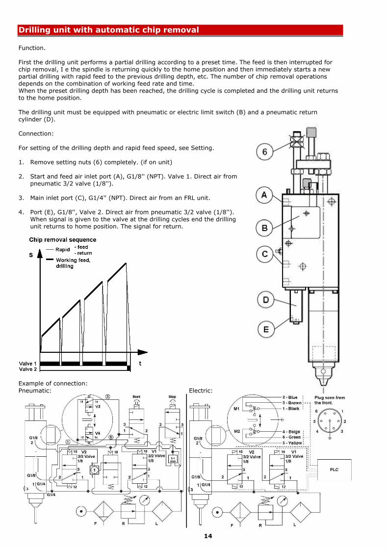
Drilling unit with automatic chip removal
Function.
First the drilling unit performs a partial drilling according to a preset time. The feed is then interrupted for chip removal, I e the spindle is returning quickly to the home position and then immediately starts a new partial drilling with rapid feed to the previous drilling depth, etc. The number of chip removal operations depends on the combination of working feed rate and time. When the preset drilling depth has been reached, the drilling cycle is completed and the drilling unit returns to the home position.
The drilling unit must be equipped with pneumatic or electric limit switch (B) and a pneumatic return cylinder (D). Connection:
For setting of the drilling depth and rapid feed speed, see Setting.
1. Remove setting nuts (6) completely. (if on unit)
2. Start and feed air inlet port (A), G1/8'' (NPT). Valve 1. Direct air from pneumatic 3/2 valve (1/8'').
3. Main inlet port (C), G1/4'' (NPT). Direct air from an FRL unit.
4. Port (E), G1/8'', Valve 2. Direct air from pneumatic 3/2 valve (1/8''). When signal is given to the valve at the drilling cycles end the drilling unit returns to home position. The signal for return.
Example of connection:
Pneumatic: Electric:
15
Maintenance instruction
Daily check:
- Check the air-pressure on the FRL-unit, 6 – 7 bar (87 – 101.5 Psi). Max 7 bar (101.5 Psi). - Check for any leakages of air or oil. If a leakage is detected, contact service staff. - Check the oil-level indicator pin (10). If the oil-level indicator has sunken to approx. 1 mm (.039 In) above the level of the housing, contact service staff. For refilling see instruction Every 6 months below. Weekly check:
- Check that the oil-mist lubrication is working, approx. 1 drop/10-20 cycles. 1 drop = 15 mm3 (.000528 fl.oz. (UK), .000507 fl.oz. (US)) - Check that the drilling unit is clean. Monthly check:
- Check that no abnormal play is present in the drilling spindle.
- Check that external silencer is not clogged. - Check that the air filter in the FRL unit is working or replace the air filter. Every 6 months:
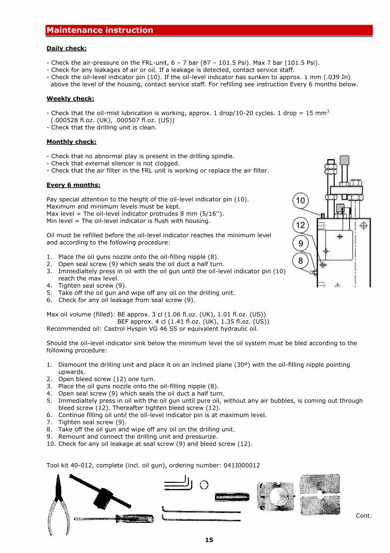
Pay special attention to the height of the oil-level indicator pin (10). Maximum and minimum levels must be kept. Max level = The oil-level indicator protrudes 8 mm (5/16''). Min level = The oil-level indicator is flush with housing. Oil must be refilled before the oil-level indicator reaches the minimum level and according to the following procedure:
1. Place the oil guns nozzle onto the oil-filling nipple (8). 2. Open seal screw (9) which seals the oil duct a half turn.
3. Immedialtely press in oil with the oil gun until the oil-level indicator pin (10) reach the max level.
4. Tighten seal screw (9).
5. Take off the oil gun and wipe off any oil on the drilling unit. 6. Check for any oil leakage from seal screw (9). Max oil volume (filled): BE approx. 3 cl (1.06 fl.oz. (UK), 1.01 fl.oz. (US)) BEF approx. 4 cl (1.41 fl.oz. (UK), 1.35 fl.oz. (US)) Recommended oil: Castrol Hyspin VG 46 SS or equivalent hydraulic oil.
Should the oil-level indicator sink below the minimum level the oil system must be bled according to the following procedure: 1. Dismount the drilling unit and place it on an inclined plane (30º) with the oil-filling nipple pointing
upwards.
2. Open bleed screw (12) one turn. 3. Place the oil guns nozzle onto the oil-filling nipple (8).
4. Open seal screw (9) which seals the oil duct a half turn. 5. Immedialtely press in oil with the oil gun until pure oil, without any air bubbles, is coming out through
bleed screw (12). Thereafter tighten bleed screw (12). 6. Continue filling oil until the oil-level indicator pin is at maximum level. 7. Tighten seal screw (9). 8. Take off the oil gun and wipe off any oil on the drilling unit.
9. Remount and connect the drilling unit and pressurize. 10. Check for any oil leakage at seal screw (9) and bleed screw (12). Tool kit 40-012, complete (incl. oil gun), ordering number: 041J000012
Cont.
16
Every 12 months:
Perform overhauling and clean the air motor every 12 months alternatively after 1500 – 2000 working hours operation depending on which occurs first. Planetary gear, ball bearings and needle bearings are greased
with ball bearing grease. The air motor is of so called vane type. The air motors service life depends to a high degree on the air motors operating conditions. The vanes in an air motor intended for
oil-mist lubrication have a life expectancy between 1500 to 2000 working hours at normal operation conditions. Other mechanical parts such as bearing have a service life between 3000 – 5000 hours. The service life for an air motor intended for lubrication free operation is 1/3 of the service life compared with a lubricated air motor at normal operation. If hard operation, overhauling and cleaning should be perfomed with tighter intervals.
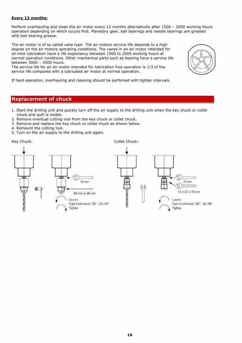
Replacement of chuck
1. Start the drilling unit and quickly turn off the air supply to the drilling unit when the key chuck or collet chuck and quill is visible. 2. Remove eventual cutting tool from the key chuck or collet chuck.
3. Remove and replace the key chuck or collet chuck as shown below. 4. Remount the cutting tool. 5. Turn on the air supply to the drilling unit again. Key Chuck: Collet Chuck:
17
Type
Speed *
(idle) Rpm
Speed
(at max power)
Rpm
Torque
(at max power)
Nm
Torque
(at max power)
Lbf-in
BE 225, BEF 225 500 250 9,9 87,62
BE 228, BEF 228 800 400 6,0 53,10
BE 2211, BEF 2211 1100 550 4,3 38,06
BE 2222, BEF 2222 2200 1100 2,4 21,24
BE 2236, BEF 2236 3600 1800 1,5 13,28
BE 2249, BEF 2249 4900 2450 1,1 9,74
BE 22150, BEF 22150 15000 7500 0,25 2,21
BE 22220 21500 11000 0,25 2,21 * Lubrication free air motors have 95% of shown idle speed.
Type Power, kW
Power, Hp
BE 225, BEF 225 0,25 0,33
BE 228, BEF 228 0,25 0,33
BE 2211, BEF 2211 0,25 0,33
BE 2222, BEF 2222 0,25 0,33
BE 2236, BEF 2236 0,25 0,33
BE 2249, BEF 2249 0,25 0,33
BE 22150, BEF 22150 0,25 0,33
BE 22220 0,25 0,33
Technical information
Technical features, at 6,3 Bar (91.35 Psi):
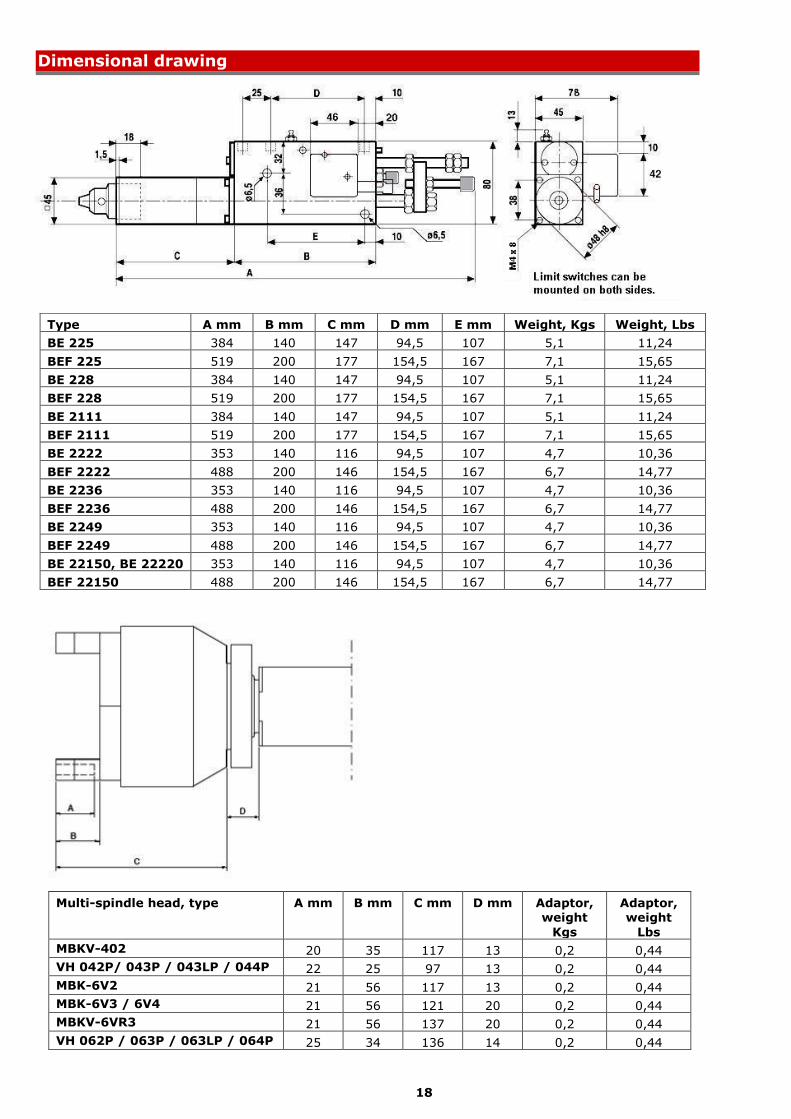
Thrust, axial force : Max. 600 N (135 Lbf) Power, air motor : See Power table below. Stroke : BE max. 30 mm (1 3/16''), 100% controlled. BEF total, 60 mm (2 3/8'') of wich 45 mm (1 3/4'') is 100% controlled. CC spindle spacing : Single spindle min. 45 mm (1 3/4") Double spindle head min. 11 mm (7/16")
Run-out at spindle nose : Max. 0,03 mm (.001 In) Depth, accuracy : +/- 0,01 mm (.0004 In) Rapid advance rate : 10 m/min (400 In/min Controlled feed rate : > 0,01 m/min (> .4 In/min) Working pressure range : 6 – 7 bar. Max 7 bar (85 – 100 Psi. Max. 101.5 Psi) Air consumption : < 0,3 Nm3/min (< 12 Cfm)
Ambient temperature : +10º - +40º C. (+50º - +104º F) Sound level : 70 dB(A)
Spindle thread for chuck : 3/8'' – 24 UNF Chuck : As standard the drilling unit is fitted with an ordinary key chuck Ø 0,5 – 6,5 mm (.02 – 1/4''). A larger key chuck and collet chuck with collets are available as an option. Electric limit switches : Micro-switch: 10A 125V AC / 10A 250V AC
IP classification : N/A Power, at 6,3 Bar (91.35 Psi):
Typical air motor caracteristics. Speed and torque, at 6,3 Bar (91.35 Psi):
Maximum power is produced when the drilling spindle during operation rotates at half speed max speed. For other data such as drilling capacity we refer to our website www.e2systems.com.
The warranty period for the product is 4 000 000 drilling cycles or 12 months after installation/
commissioning or 18 months after delivery, which of these occurs first, and provided that the product installed/stored in a satisfactory manner and that the product is used in normal operation, the mounting/
clamping and handling conditions. The warranty is not valid if unauthorized change/modification have been performed on the product and that this may make the product unsafe.
Environmental declaration
Drilling unit, Type BE 22 or BEF 22
Housing : Aluminium Quill : Brass Other parts : Aluminium, brass and steel
Gaskets : Rubber Hydraulic oil : Oil. The drilling unit contains a small amount hydraulic oil.
Housing, quill and other metallic parts : Dispose as metal waste; Aluminium, brass and steel. Gaskets : Dispose as combustable waste. Hydraulic oil : Dispose as hazardous waste.
All information contained in this manual is intended to be correct; however information and data in this manual are subject to change without notice. E2systems makes no warranty of any kind of regard to this information or data. Further, E2systems is not responsible for any omissions or errors or consequential
damaged caused by the user of the product. E2systems reserves the right to make manufacturing changes which may not be included in this manual.


![[제121회] - bef-pe.inup.co.kr](https://static.documents.pub/doc/80x56/61ae70ec80ff1c48a85ffe9a/121-bef-peinupcokr.jpg)


