56
Air Leakage Testing and Air Sealing in Existing Multifamily Units Jordan Dentz and Francis Conlin Advanced Residential Integrated Energy Solutions October 2012

Air Leakage Testing and Air Sealing in Existing Multifamily Units Jordan Dentz and Francis Conlin Advanced Residential Integrated Energy Solutions
October 2012

NOTICE
This report was prepared as an account of work sponsored by an agency of the United States government. Neither the United States government nor any agency thereof, nor any of their employees, subcontractors, or affiliated partners makes any warranty, express or implied, or assumes any legal liability or responsibility for the accuracy, completeness, or usefulness of any information, apparatus, product, or process disclosed, or represents that its use would not infringe privately owned rights. Reference herein to any specific commercial product, process, or service by trade name, trademark, manufacturer, or otherwise does not necessarily constitute or imply its endorsement, recommendation, or favoring by the United States government or any agency thereof. The views and opinions of authors expressed herein do not necessarily state or reflect those of the United States government or any agency thereof.
Available electronically at http://www.osti.gov/bridge
Available for a processing fee to U.S. Department of Energy and its contractors, in paper, from:
U.S. Department of Energy Office of Scientific and Technical Information
P.O. Box 62 Oak Ridge, TN 37831-0062
phone: 865.576.8401 fax: 865.576.5728
email: mailto:[email protected]
Available for sale to the public, in paper, from: U.S. Department of Commerce
National Technical Information Service 5285 Port Royal Road Springfield, VA 22161 phone: 800.553.6847
fax: 703.605.6900 email: [email protected]
online ordering: http://www.ntis.gov/ordering.htm
Printed on paper containing at least 50% wastepaper, including 20% postconsumer waste
iii
Air Leakage Testing and Air Sealing in Existing Multifamily Units
Prepared for:
Building America
Building Technologies Program
Office of Energy Efficiency and Renewable Energy
U.S. Department of Energy
Prepared by:
Jordan Dentz and Francis Conlin
Advanced Residential Integrated Energy Solutions
The Levy Partnership, Inc., 1776 Broadway, Suite 2205
New York, NY 10019
NREL Technical Monitor: Mike Gestwick
Prepared under Subcontract No. KNDJ-0-40347-00
October 2012

iv
[This page left blank]
v
Contents List of Figures ............................................................................................................................................ vi List of Tables ............................................................................................................................................. vii Definitions ................................................................................................................................................. viii Executive Summary ................................................................................................................................... ix Acknowledgments ...................................................................................................................................... x 1 Introduction ........................................................................................................................................... 1
1.1 Background ..........................................................................................................................1 1.2 Importance of Air Sealing Existing Multifamily Buildings ................................................3
1.2.1 Moisture ...................................................................................................................3 1.2.2 Indoor Air Quality....................................................................................................3 1.2.3 Equipment Performance...........................................................................................4
2 Experiment ............................................................................................................................................ 5 3 Results ................................................................................................................................................... 7 4 Modeled Energy Savings ................................................................................................................... 11 5 Cost Effectiveness ............................................................................................................................. 13 6 Conclusion .......................................................................................................................................... 15 References ................................................................................................................................................. 16 Bibliography .............................................................................................................................................. 18 Appendix A. Floor Plans for Yorktowne Apartments ............................................................................ 19 Appendix B. Climate Zones...................................................................................................................... 21 Appendix C. Photos .................................................................................................................................. 22 Appendix D. Specifications ...................................................................................................................... 28 Appendix E. Air Sealing Instructions ...................................................................................................... 33
vi
List of Figures Figure 1. Yorktowne apartments ............................................................................................................... 5 Figure 2. Climate zones for RECS database (U.S. Energy Information Administration, 2009) ......... 21 Figure 3. Crawl space viewable through living room register at disconnected duct ........................ 22 Figure 4. Dropped ceiling pipe penetration ............................................................................................ 22 Figure 5. Dropped ceiling wire penetration ............................................................................................ 22 Figure 6. Dropped ceiling bypass into soffit over sink ......................................................................... 22 Figure 7. Inside kitchen soffit .................................................................................................................. 23 Figure 8. Inside kitchen soffit with pipes ................................................................................................ 23 Figure 9. Gap under new window ............................................................................................................ 23 Figure 10. Window doesn’t close ............................................................................................................ 23 Figure 11. Window leakage ...................................................................................................................... 24 Figure 12. Semi‐sealed dropped ceiling with pipe ................................................................................ 24 Figure 13. Semi‐sealed dropped ceiling opening .................................................................................. 24 Figure 14. Semi‐sealed dropped ceiling ................................................................................................. 24 Figure 15. Open cavity between kitchen and living room ..................................................................... 25 Figure 16. Hatch (opened to get picture) between bathrooms and plumbing penetrations ............. 25 Figure 17. View into plumbing penetration ............................................................................................ 25 Figure 18. Water heater penetrations and hatch into plumbing access in bathroom closet ............ 25 Figure 19. Cavity between units under tub ............................................................................................. 26 Figure 20. Window leakage ...................................................................................................................... 26 Figure 21. Behind dropped ceiling .......................................................................................................... 26 Figure 22. Open cavities through dropped ceiling ................................................................................ 26 Figure 23. Open chase through dropped ceiling ................................................................................... 27 Figure 24. Plumbing penetrations ........................................................................................................... 27 Figure 25. Plumbing penetrations into attic ........................................................................................... 27 Unless otherwise indicated, all figures were created by AIRES.

vii
List of Tables Table 1. Construction Characteristics and Their National Representation .......................................... 6 Table 2. Summary of Unit Characteristics ................................................................................................ 6 Table 3. Temporary Air Sealing Results ................................................................................................... 7 Table 4. Average of Pressure Mapping Results (Number of Locations Investigated) ......................... 8 Table 5. Guarded Test Results .................................................................................................................. 8 Table 6. Average Preretrofit Total Envelope Leakage and Reduction ................................................... 9 Table 7. Estimated Pre-Retrofit Leakage to Outside and Percentage Reduction ............................... 11 Table 8. Average Modeled Savings per Unit .......................................................................................... 11 Table 9. Modeled Energy Savings in Percent ......................................................................................... 12 Table 10. Cost per CFA per Leakage Reduction .................................................................................... 13 Table 11. Return on Investment ............................................................................................................... 14 Table 13. Pictures from 2030 Bedford Unit 8 .......................................................................................... 26 Unless otherwise indicated, all tables were created by AIRES.

viii
Definitions
ACH50 Air changes per hour at 50 Pascals pressure differential
ARIES Advanced Residential Integrated Energy Solutions Collaborative
ASHRAE American Society of Heating, Refrigerating and Air-Conditioning Engineers
BEopt Building Energy Optimization software program
CFA Conditioned floor area
CFM50 Cubic feet per minute of air at 50 pascals pressure differential
IEQ Indoor environmental quality
GWB Gypsum wall board
HVAC Heating, ventilation, and air conditioning
LEED Leadership in Energy and Environmental Design
NREMD National Residential Efficiency Measures Database
RECS Residential Energy Consumption Survey

ix
Executive Summary
Techniques for measuring and sealing envelope air leakage in multifamily buildings are not well defined or developed, particularly when compared to the methods used for characterizing air leakage in single family detached homes. Part of the reason for the lag in understanding air flow patterns in multifamily buildings is the wide variety of possible building configurations and the difficulty of separating total infiltration into its components, which can include leakage to the outside, air movement between units, and leakage between units and common spaces.
The literature underscores the importance of controlling air leakage in multifamily buildings. For example, a Lawrence Berkeley National Laboratory (Gadgil et al. 2006) study concluded that multiunit residential buildings and commercial buildings are about two times as leaky as single family detached homes per unit surface area, indicating that there may be substantial energy savings associated with air sealing multifamily buildings. The study also concluded that transport of pollutants between apartments and within mixed-use buildings has health consequences and that sealing these buildings from outside air infiltration without reducing the internal transport of air may exacerbate indoor air quality problems.
There are a number of reasons to air seal a multifamily building, all of which further Building America’s goals. Foremost among these is to control heat loss and gain through the building envelope to save energy and improve comfort by eliminating drafts and temperature swings. Other reasons to air seal include: preventing moisture problems that may result when uncontrolled air leaks introduce humid air into building cavities; minimizing air movement between apartments and other spaces (including crawlspaces and attics) to prevent transfer of contaminants and improve indoor environmental quality (IEQ); and to reduce thermal loads that can be served by smaller capacity heating and cooling equipment.
The research identified common air leakage pathways in one type of low-rise multifamily building common in mixed-humid climates. The report recommends corrective actions for cost effectively remediating leakage.
The research findings are based on the retrofit of a 244-unit low-rise multifamily building complex in Durham, North Carolina. A comprehensive air sealing program was part of a more extensive retrofit effort. Pre- and post-retrofit enclosure leakage tests were conducted on all units, and detailed diagnostics were performed on a representative sample of units. On average, total leakage was reduced by nearly half, from 16.4 air changes per hour at 50 Pascals pressure differential (ACH50) to 9.1 ACH50. Costs for air sealing were $0.14 per ft2 of conditioned floor area (CFA), substantially lower than estimates found in the National Residential Efficiency Measures Database (NREMD). The low cost is due, in part, to the relatively large scale of the project, allowing for more aggressive material pricing and efficient use of labor. The costs also suggest that the NREMD data may not be appropriate for estimating multifamily costs.
The team modeled the Durham project using the Building Energy Optimization software to project the resulting space conditioning energy cost savings. Using an estimate that 88% of the envelope air leakage is to the outside (based on guarded tests performed at the site), an energy savings of 10% to 19% was projected due to the air sealing retrofit.

x
Acknowledgments
The Advanced Residential Integrated Energy Solutions (ARIES) Collaborative would like to recognize the support of the U.S. Department of Energy’s Building America Program and Michael Gestwick of the National Renewable Energy Laboratory for technical guidance. This project would not have been possible without the support and participation of Phillip Foley and Alex Burris of Ginkgo Residential, Charlotte, NC. Thanks are also due to Marty Meadows of PowerSecure, Inc.
1
1 Introduction
Procedures for locating and sealing envelope air leakage in existing multifamily buildings and individual apartment units differ from those for single family detached homes. For multifamily buildings, air movement between individual units, between units and the outdoors (including often dirty crawlspaces and attics), and between units and common areas complicate the task of characterizing and sealing air leakage pathways. Retrofit air sealing techniques for multifamily buildings are not as well documented or developed as those for single family construction (Gadgil et al. 2006). The range of construction methods, styles of buildings and construction details unique to multifamily structures contribute to greater variability in air leakage pathways.
While interunit air leakage may not result in significant energy loss compared to leakage to the outside, it is generally recognized that preventing interunit leakage through compartmentalization of living units is desirable from an indoor environmental quality (IEQ) perspective. A study in Minnesota revealed that almost 50% of renters said that secondhand smoke gets into their apartment from somewhere else in the building (Bohac and Hewett 2004). Of those surveyed, more than one quarter said that smoke bothers them “a lot” or “so much I’m thinking of moving.”
This report identifies the most important air leakage pathways typically found in two-story townhouse developments that are commonly found in the mixed-humid climate. The study includes recommendations for cost effectively identifying and correcting air leakage in these buildings.
1.1 Background There are approximately 25.8 million multifamily units in the United States, according to the 2005 American Housing Survey (U.S. Census Bureau 2006). Eighteen million of these units are in buildings with fewer than 20 units and are most likely low-rise buildings.
At present, limited information is available on air leakage in multifamily homes. The California Energy Commission compiled and analyzed available data concerning indoor/outdoor air leakage rates and building leakiness parameters for commercial buildings and apartments in the U.S. and other developed countries (Gadgil et al. 2006). The researchers found data for only 78 multiunit residential buildings in North America. From these data, the authors concluded that multiunit residential buildings and commercial buildings “seem to be about twice as leaky as single family detached homes, per unit of building envelope area.” This suggests that there may be substantial energy savings potential for air sealing these building types. The study observed little systematic variation in envelope leakage with construction type, activity type, height, size, or location. Gadgil et al. (2006) concluded that a more important issue needing further study may be the transport of pollutants between units in apartment and mixed-use buildings, which may expose occupants to high levels of tobacco smoke or a mixture of commercial air contaminants including nail polish, dry cleaning fumes, or other volatile organic compounds. Additionally, they suggested that sealing air infiltrating from the outside without reducing the transport of air between units may exacerbate interzonal air exchange.
2
Several green building programs and building standards provide airtightness targets.1 Among these, only Leadership in Energy and Environmental Design (LEED) 2009 for Existing Buildings offers specific guidance for multifamily buildings. The LEED standard requires control of environmental tobacco smoke transfer between residential units, limiting the air leakage area of each unit to 1.25 in.2/100 ft2 of enclosure area (i.e., the sum of all wall, ceiling and floor areas) (U.S. Green Building Council 2008).
While specific leakage locations and their severity vary greatly from building to building, the literature indicates that the following leakage areas are among the most significant in multifamily structures and are often worthy of sealing (Brabon 2011; Hayes 1995; Keefe 1995; Oregon Building Codes Division 2008; Steven Winter Associates 2010):
• Attic bypasses, such as through common walls, chases, dropped soffits, open core block walls, and overhangs.
• Intersections of floors, walls, and ceilings, especially where structural members extend across multiple units.
• Central shafts and mechanical chases/rooms between units.
• Plumbing penetrations and the common wall between bathrooms of adjoining units, especially underneath bathtubs and showers and at heating pipe penetrations.
• Electrical panel, gas line, and other penetrations into the conditioned space.
• Space between window/door jambs and the framing, and door latch holes through the door frame.
• Cutouts in the drywall around the perimeter of fans, vents, duct shafts, air conditioner sleeves, and medicine cabinets.
• Wall and ceiling penetrations such as electrical outlets, recessed lighting, thermostats, and intercoms.
• Any areas where renovations have altered the original construction.
This research documents total enclosure air leakage, estimates leakage amounts by site, and measures the improvement in airtightness and the cost of production-scale remediation in affordable low-rise wood-frame multifamily housing stock. Although the research was conducted on buildings in the mixed-humid climate, the results are relevant to low-rise multifamily buildings in all climate zones.
1 In new residential construction (not specific to multifamily), ENERGY STAR Version 3 requires a maximum infiltration level of 3 to 6 ACH50 depending on climate (U.S. Department of Energy | U.S. Environmental Protection Agency, 2011). For commercial buildings, ASHRAE 189.1 sets the upper limit of whole building leakage to 0.4 cfm/ft2of envelope area tested at 75 Pascals (American Society of Heating, Refrigerating and Air-Conditioning Engineers, Inc., 2009), and the U.S. Army Corps of Engineers has specified 0.25 cfm75/envelope ft2 (Zhivov, et al., 2010).
3
1.2 Importance of Air Sealing Existing Multifamily Buildings Air sealing older buildings, which were most likely built with little attention to enclosure tightness, is an essential ingredient to improving their energy efficiency. Air sealing alone can save 10% to 20% of single family home energy use (Baechler et al. 2010). Cutting down on heat loss or gain from uncontrolled infiltration is the first step in a retrofit and a prerequisite for implementing other energy savings measures, such as adding insulation or upgrading equipment.
Several reasons for air sealing a multifamily building, all of which further Building America’s goals, include:
• Controlling heat loss and/or gain through the envelope in order to save energy.
• Improving comfort by eliminating drafts and temperature swings.
• Avoiding moisture problems that may form when uncontrolled air leaks bring moisture into building cavities.
• Minimizing air movement between apartments and other spaces (including crawlspaces and attics) to prevent transfer of contaminants and improve IEQ.
• Improving equipment performance.
The economic impact of air sealing can most readily be measured by energy savings and, for the this project, is estimated and presented in Section 5. However, all five factors listed above convey benefits to the building owner and occupant. Moisture, IEQ and equipment performance are discussed in more detail below.
1.2.1 Moisture Moisture problems may arise when unintended air infiltration brings moisture into building cavities. Air sealing can avert moisture problems such as accumulation of moisture in materials that can cause material deterioration (Zhivov and Anis 2010). Another benefit of air sealing is the potential to reduce duct loss to the outside and mitigate moisture problems in semiconditioned spaces where cooling ducts are located.
Many multifamily buildings that were not originally built with central cooling have uninsulated ducts in floor cavities between units. These cavities can have a great deal of outside air infiltration and therefore high humidity levels much of the year. Moisture-laden air in the vicinity of the now cold ducts can condense. Air sealing the band joists and other areas to reduce air infiltration into the floor cavity reduces the potential for condensation on the ducts. Additionally, proper air sealing brings the ducts more within the conditioned space, reducing the need for remedial duct sealing in these difficult-to-access areas (Zhivov and Anis 2010).
1.2.2 Indoor Air Quality Total building envelope air sealing can minimize air movement between apartments and other spaces, preventing transfer of contaminants and maintaining better IEQ. A large body of research on secondhand smoke transmission between apartments supports the need for compartmentalization of units (Bohac and Hewett 2004).

4
Most older, low-rise multifamily buildings do not have an adequate ventilation system; rather, they depend on infiltration to bring in outside air. If significant infiltration reductions are achieved through an air sealing retrofit, the amount of infiltrating outside air may be inadequate for fresh air needs, and a new fresh air ventilation system may be required to make up for the lost infiltration. This could add to the cost of a retrofit. Furthermore, if pressure balances change, combustion safety may be impacted (i.e., draft of flue gases could be affected). To correct pressure imbalances, contractors may need to alter the equipment or the combustion appliance zone to maintain adequate flue draft.
While IEQ is important for occupant health and comfort (including preventing odor transmission) the cost associated with improving IEQ cannot be recouped by energy savings. Sealing interior air leaks to adjacent apartments or common spaces does not save significant amounts of energy because the areas are conditioned to the same or a relatively similar temperature, and energy loss occurs only across a temperature gradient.
1.2.3 Equipment Performance Space heating, cooling, and ventilation systems perform better when they are not contending with excessive air infiltration. Reducing air infiltration correspondingly reduces the quantity of particulate matter being brought into the building and the heating, ventilating, and air conditioning (HVAC) system. Reducing the introduction of particulates reduces the frequency of required filter changes and the fouling of heat exchangers and other equipment. Overall, less infiltration improves HVAC performance and reduces system maintenance.
Air sealing also can reduce a building’s space conditioning loads, resulting in the need for less expensive, lower capacity equipment at the time of replacement. If equipment is not replaced after air sealing, the lowered leakage rate may result in HVAC equipment being oversized. This may reduce both the efficiency of the cooling equipment and its ability to provide adequate dehumidification as well as short-cycling that can lead to premature equipment failure.

5
2 Experiment
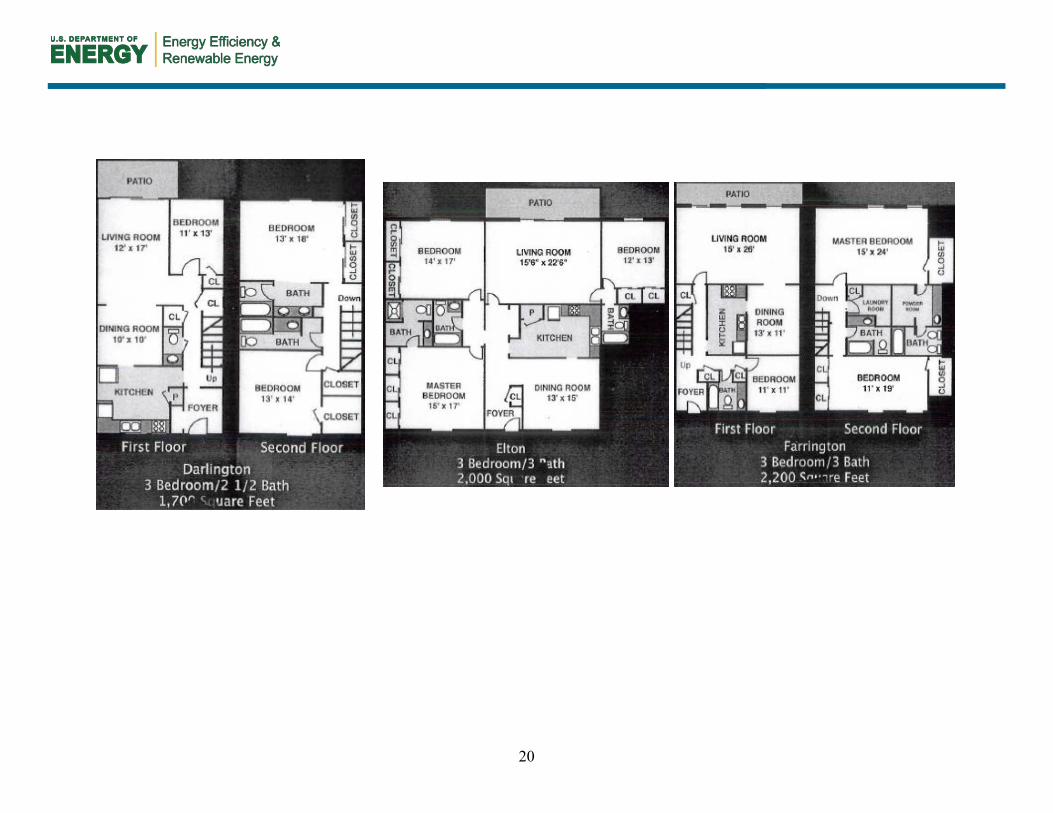
Researchers from the Advanced Residential Integrated Energy Solutions Collaborative (ARIES) partnered with Ginkgo Residential, a developer and owner of affordable multifamily properties across the southern U.S., to improve enclosure airtightness of a recently acquired apartment complex in Durham, North Carolina. The air sealing work was done as part of a general rehabilitation of the approximately 40-yr-old property. The test site, the Yorktowne apartments on Bedford Street in Durham, is in the mixed-humid climate (Figure 1). There are 244 apartments in 30 single-story and two-story brick- and siding-clad buildings constructed between 1960 and 1980. The buildings include townhome and apartment style units, with some built on slabs and others over crawlspaces. Floor plans are provided in Appendix A.
Figure 1. Yorktowne apartments
The Yorktowne apartments are typical of low-rise affordable multifamily housing stock throughout the Southeast and lower Midwest region. According to the Residential Energy Consumption Survey (RECS) database, there are more than nine million low-rise multifamily living units in climate zones 2, 3 and 4 (Appendix B) (U.S. Energy Information Administration 2009). Some key construction characteristics tabulated by RECS and relevant to air sealing retrofits are shown in Table 1 below.

6
Table 1. Construction Characteristics and Their National Representation
Database Construction Characteristic Option Number of
Units Percentage of
Total Units
RECS 2005; Climate zones
2, 3, 4; Buildings with 5 or
more units and up to 3
floors
Wall Type
Siding (wood, alum, vinyl, steel, shingle) 2,927,537 31%
Masonry (brick, stone, concrete) 4,493,652 48%
Stucco 1,951,117 21%
Year Constructed
Before 1940 794,925 8% 1940–1969 2,064,695 22%
1970–Present 6,285,739 67%
Number of Floors
1 1,192,992 13% 2 4,259,471 45% 3 3,925,567 42%
As part of this project, ARIES conducted the following tasks:
1. Documented the pre-retrofit conditions in selected units by recording total envelope leakage and conducting a variety of diagnostic tests to quantify the impacts of specific leakage sites (photographs of typical leakage sites may be found in Appendix C).
2. Developed a set of specifications (Appendix D) and a graphic-laden how-to guide specific to the project for the air sealing contractor (Appendix E).
3. Inspected the work of the air sealing contractor, recommending corrective actions when necessary.
4. Tested a sample of units after completion of air sealing work to identify sources of remaining leakage and collected the air sealing contractor’s pre- and post-retrofit air leakage test data (65 units with pre-retrofit data and 34 with both pre- and post-retrofit data).
Characteristics of the units for the entire data set are listed in Table 2.
Table 2. Summary of Unit Characteristics
Characteristic Number of Units 65
Average Conditioned Floor Area (CFA) (ft2) 1,526
Units on Slab 22 Units on Crawlspace 43
7
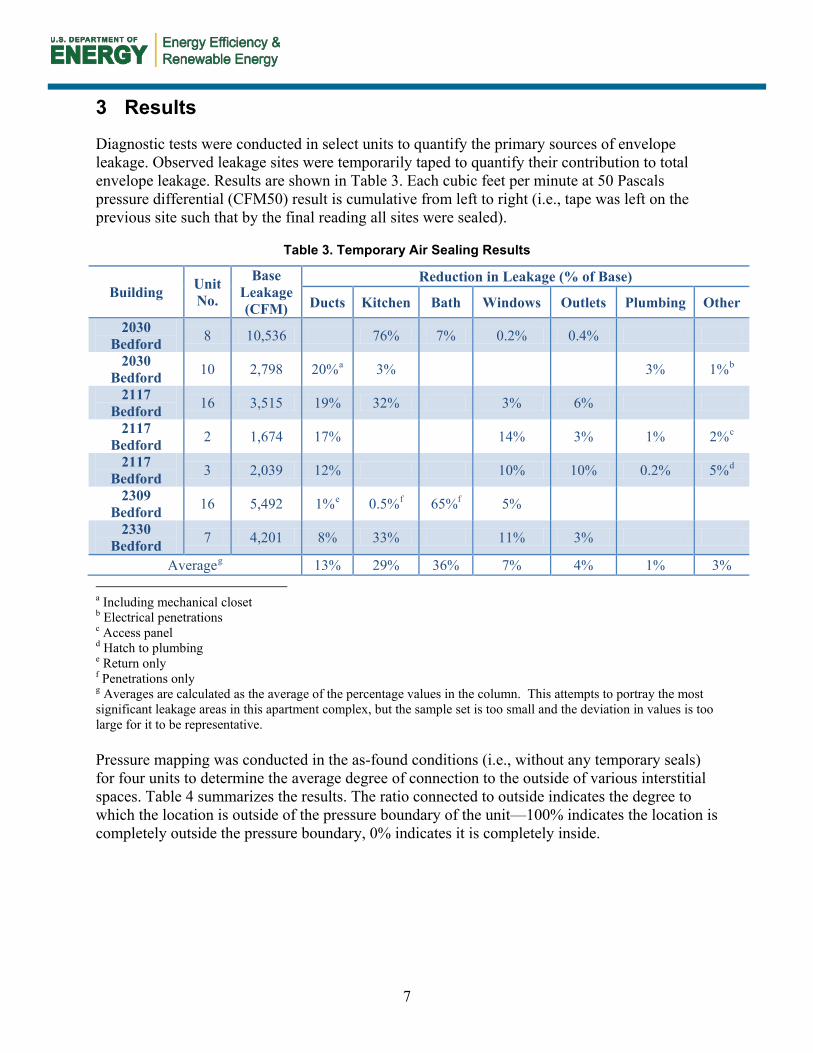
3 Results
Diagnostic tests were conducted in select units to quantify the primary sources of envelope leakage. Observed leakage sites were temporarily taped to quantify their contribution to total envelope leakage. Results are shown in Table 3. Each cubic feet per minute at 50 Pascals pressure differential (CFM50) result is cumulative from left to right (i.e., tape was left on the previous site such that by the final reading all sites were sealed).
Table 3. Temporary Air Sealing Results
Building Unit No.
Base Leakage (CFM)
Reduction in Leakage (% of Base)
Ducts Kitchen Bath Windows Outlets Plumbing Other
2030 Bedford 8 10,536 76% 7% 0.2% 0.4%
2030 Bedford 10 2,798 20%a 3% 3% 1%b
2117 Bedford 16 3,515 19% 32% 3% 6%
2117 Bedford 2 1,674 17% 14% 3% 1% 2%c
2117 Bedford 3 2,039 12% 10% 10% 0.2% 5%d
2309 Bedford 16 5,492 1%e 0.5%f 65%f 5%
2330 Bedford 7 4,201 8% 33% 11% 3%
Averageg 13% 29% 36% 7% 4% 1% 3% a Including mechanical closet b Electrical penetrations c Access panel d Hatch to plumbing e Return only f Penetrations only g Averages are calculated as the average of the percentage values in the column. This attempts to portray the most significant leakage areas in this apartment complex, but the sample set is too small and the deviation in values is too large for it to be representative. Pressure mapping was conducted in the as-found conditions (i.e., without any temporary seals) for four units to determine the average degree of connection to the outside of various interstitial spaces. Table 4 summarizes the results. The ratio connected to outside indicates the degree to which the location is outside of the pressure boundary of the unit—100% indicates the location is completely outside the pressure boundary, 0% indicates it is completely inside.

8
Table 4. Average of Pressure Mapping Results (Number of Locations Investigated)
Location Outside Connection Factor
Intended Interior Space
Interior living area 0% Common wall cavity (6) 75% Exterior wall cavity (6) 61% Interior wall cavity (2) 52%
Ceiling cavity between floors (1) 70% Kitchen chase (1) 55% Kitchen soffit (1) 88%
Ducts (4) 69%
Intended Exterior Space
Dropped ceilings (3) 73% Crawl space (1) 55%
Attic (4) 73% Most interstitial spaces (common walls, ceilings) are far more connected to outside the apartment than to inside. This has important implications for duct leakage. Because ducts are frequently located in interstitial spaces in multifamily buildings, leakage will be mostly to the outside.
The low leakage reductions seen in the guarded tests2 (Table 5) are consistent with the pressure mapping results. Air infiltrating through common walls and ceilings is more likely to be drawn from the outside than from an adjacent unit under test conditions because those interstitial spaces are well connected to the outdoors.
Table 5. Guarded Test Results
Building Unit Base
Leakage (CFM)
Pre or
Post Test
Adiabatic Sides
Guarded Sides
Reduction in Leakage
(% of Base)
Interpolated Leakage to
Outside as % of Total
1800 Balmoray 15 2,412 Pre 2 1 3% 92% 2030 Bedford 6 2,685 Pre 2 1 6% 83% 2132 Bedford 23 2,302 Pre 1 1 3% 92%
1800 Balmoray 12 1,782 Post 2 2 3% 96% 1800 Balmoray 17 1,394 Post 1 1 22% 67% 2030 Bedford 6 1,546 Post 2 1 0% 100%
Average 2,020 6.2% 88% Overall average post air sealing leakage reduction is shown in Table 6.
2 A guarded test is conducted by depressurizing (or pressurizing) adjacent living units to the same pressure, thereby eliminating any driving pressure, and resultant leakage, between the two (or more) adjacent units. Guarded tests can be used to determine the portion of air leakage that goes to conditioned versus unconditioned spaces.

9
Table 6. Average Pre-Retrofit Total Envelope Leakage and Reduction
Unit Pre-Retrofit Averagea
Post-Retrofit Averageb
Average % Leakage Reductionc
CFM/CFA 2.2 1.2 48% ACH50) 16.4 9.1 48%
a Includes 65 units that had pre-retrofit testing performed. b Includes 35 units that had both pre- and post-retrofit testing performed. c Average improvement of each of the 35 cases that had both pre- and post-retrofit testing performed. Note that this
differs from the average reduction divided by the pre-retrofit average.
The major areas of envelope leakage at Yorktowne were found to be, in order of importance:
• Plumbing and electrical penetrations. Over the years, previous plumbing and appliance retrofit work at Yorktowne was completed without an air sealing protocol in effect. Repair work (and possibly original installation) was completed with little regard for air sealing gaps between plumbing and electrical penetrations and the air barrier material. At some locations, sections of the air barrier material—interior gypsum wallboard (GWB) in Yorktowne’s case—were completely removed to allow repair access and were not replaced after the repairs were completed. Unsealed penetrations of this type were most commonly found in HVAC closets, above dropped ceilings, under and inside cabinets, and behind appliances, but were also present in the living space.
• Soffits / dropped ceilings. Dropped ceilings at Yorktowne were found to conceal a variety of air barrier deficiencies. The air barrier material above the dropped ceiling was not sealed at material intersections, permitting air leakage between the living space and the vented attic. Plumbing and electrical penetrations hidden by the dropped ceiling were not air sealed. Often, large sections of the air barrier material were removed in order to permit repair access and were not replaced or sealed after repairs. For dropped ceilings in top floor locations, missing sections of air barrier material resulted in direct (visible) connectedness to the vented attic and, hence, strong connection to the outdoors. Blower door tests conducted while temporarily sealing the kitchen from the rest of the apartment with adhesive films illustrated profound air leakage into the attic and other building cavities strongly connected to the outside.
• Ductwork. Duct leakage to the outside at Yorktowne was substantial due to improper installation, deterioration over time, or other causes. Missing or deteriorated duct boots resulted in exchange of air between the living area and the crawlspaces and attic where air quality is relatively poor. Duct leakage within wall cavities sometimes resulted in moisture signatures inside the living space where cool, uninsulated ducts and contact with outside air resulted in water staining. Air sealing retrofits did little to remedy duct leakage.
• Windows. The original windows at Yorktowne had reached the end of their serviceable lives. Closing/sliding/locking mechanisms, weatherstripping, and the panes had broken or deteriorated over time to such an extent that gaps of 1 in. or greater were common. The deteriorated state of the windows increased heating/cooling costs, negatively affected
10
occupant comfort, allowed pest infiltration, and posed a potential security problem. The original installation was completed without an air sealing strategy in effect and, as such, permitted larger-than-expected air leakage through the areas of framing just outside the window units.
• Floor-to-wall intersections. During Yorktowne’s original construction, bottom plates were not sealed or gasketed to subflooring, resulting in greater-than-expected air leakage into wall cavities at the floor-to-wall intersections. GWB interior walls generally do not completely reach the subflooring material. The gap created by the installation of the GWB, combined with the lack of bottom plate sealing, resulted in voids that permit air leakage into the unconditioned space of the wall cavities.

11
4 Modeled Energy Savings
In order to quantify the energy cost savings resulting from air sealing in multifamily buildings typical of the mixed-humid and cold climates, pre-retrofit and post-retrofit conditions were modeled for a typical apartment and a typical townhome using Building Energy Optimization (BEopt) software. The models project the energy and cost savings for three climate locations using the average pre- and post-retrofit air leakage results found in the field.
Adjustments were made to the BEopt models to replicate multifamily dwellings as closely as possible. Demising walls, floors, and ceilings were modeled as windowless, with an R-value of 100, to replicate adiabatic conditions. Because walls cannot be modeled individually, the total UA value of the dwelling was calculated using R-100 for the demising walls and common ceilings/floors and the actual insulation level for the outer walls. This value was then averaged per ft2 of wall area for entry into BEopt. Furthermore, air infiltration levels were adjusted before entry into BEopt because air leakage between conditioned spaces in multifamily buildings does not affect total energy consumption. Therefore, only air infiltration to the outside was used for energy modeling. The average fraction of leakage to the outside (88%) is based on the guarded test results presented in Table 5. Air leakage values used for modeling are shown in Table 7. While the Yorktowne apartments have heat pumps, the savings are shown for both heat pumps and electric furnaces.
Table 7. Estimated Pre-Retrofit Leakage to Outside and Percentage Reduction
Unit Pre-Retrofit Average
Post-Retrofit Average
Average % Leakage Reduction
CFM/CFA 1.9 1.1 42% ACH50 14.4 8.0 42%
Table 8 presents the modeled savings of the air sealing retrofits at Yorktowne using the numbers from Table 7. Table 9 presents the savings in percentage terms.
Table 8. Average Modeled Savings per Unit
Location
Townhome Apartment Heat Pump Electric Furnace Heat Pump Electric Furnace
MMBtu /yr $/yr MMBt
u /yr $/yr MMBtu /yr $/yr MMBt
u /yr $/yr
Durham, NC 4.6 $34.97 12.0 $92.07 3.2 $24.67 5.8 $44.49
Cincinnati, OH 9.2 $73.62 19.3 $154.1
3 7.1 $56.92 10.2 $81.24
Indianapolis, IN 20.5 $144.4
3 33.4 $235.71 14.8 $104.6
5 19.9 $140.45

12
Table 9. Modeled Energy Savings in Percent
Location
Townhome Apartment Heat Pump Electric Furnace Heat Pump Electric Furnace
% total
% space cond.
% total
% space cond.
% total
% space cond.
% total
% space cond.
Durham, NC 3% 12% 6% 14% 2% 10% 3% 10%
Cincinnati, OH 5% 14% 7% 15% 4% 14% 5% 12%
Indianapolis, IN 9% 19% 11% 19% 7% 19% 8% 17%

13
5 Cost Effectiveness
Enclosure air sealing activities can be judged on cost effectiveness based on space conditioning energy saved; however, this does not factor in two other major air sealing benefits: moisture control and IEQ. A literature search for cost effectiveness of air sealing in multifamily buildings revealed limited results. However, studies of retrofits in other building types indicate that air sealing can often be cost effective in older buildings. The following sources, summarized in Table 10, provide cost estimates for air sealing.
Table 10. Cost per CFA per Leakage Reduction
Source Leakage Reduction Total
Leakage Reduction to Outside
Cost ($/CFA)
NREMD
25% 25% 0.23–0.6 40% 40% 0.40–0.22 50% 50% 0.51–3.8 60% 60% 1.10–4.70
Bohac and Hewett (2004) 18% – 0.83
BEopt
22% 22% 0.36 29% 29% 0.63 45% 45% 1.61 49% 49% 2.30 60% 60% 2.90
Yorktowne Average 48% 42% (estimated) 0.14
The National Residential Efficiency Measures Database (NREMD) is a publicly available, centralized resource of residential building retrofit measures and costs for the U.S. building industry. The database is intended to help users determine the most cost-effective retrofit measures for improving energy efficiency of existing homes. It is accessible to software programs that evaluate the cost effectiveness of retrofit measures to improve the energy efficiency of residential buildings, as well as to home performance contractors and manufacturers of residential materials and equipment. NREMD contains cost data for residential air sealing retrofits (not specific to multifamily) estimated in dollars per ft2 of conditioned floor area ($/CFA) at a range of specified leakage reduction levels (National Renewable Energy Laboratory 2011a). Leakage is assumed to be to the outside because of the single family detached focus of the database. BEopt uses building envelope leakage reduction estimates and costs derived from the NREMD.
The Center for Energy and Environment conducted research on tobacco smoke transfer in six multifamily buildings in Minnesota in an effort to quantify air sealing measures to reduce contaminant transfer between units. The results showed a postretrofit median leakage reduction of 139 cfm50—or 18% of the total air leakage of the unit—at an average cost of 0.046 $/ CFA per 1% reduction in air leakage (Bohac and Hewett 2004). This is on the high end of the NREMD estimates. As this effort was focused on controlling air transfer between units (i.e., total leakage), it cannot be judged solely by energy costs saved.

14
Table 10 compares the cost estimates from the above-cited literature to the results of the Yorktowne retrofit, based on the air sealing contract amount and the total floor area of the retrofit project. The costs at Yorktowne were significantly lower than those cited by these sources. Based on site observation, workers were spending approximately five to six labor hours per unit (average of 1,500 ft2 floor area) on air sealing and testing. This translates into roughly 275 ft2 per labor hour. At the average cost of $210 per unit (1,500 ft2 × $0.14/ft2), the hourly rate is approximately $38 per worker.
Reasons for the lower costs at Yorktowne might include: the production nature of the work (large volume, repetitive); the competitive bid process used by the owner; the rough condition of the units at the time of retrofit (yielding “lower hanging fruit”); and the slow construction market conditions during the project.
A study of nonresidential buildings in northern climates indicated that a 40% to 70% reduction in infiltration commonly yields a 15% to 25% reduction in heating costs, or a 9% to 15% reduction in overall energy expenditure, with a payback period of less than two years (Kokko 2010). Modelling of the estimated 42% leakage to outside reduction at Yorktowne yields a 10% to 19% reduction in space conditioning costs, or a 2% to 11% reduction in overall energy expenditure, with a payback period of 0.9 to 8.6 years, depending on climate location. The return on investment based on the modeled savings is shown in Table 11.
Table 11. Return on Investment
Location Townhome Apartment
Heat Pump Electric Furnace Heat Pump Electric
Furnace Durham, NC 16% 43% 12% 21%
Cincinnati, OH 35% 72% 27% 38% Indianapolis, IN 68% 111% 49% 66%
15
6 Conclusion
Older (20+ years) low-rise affordable rental units can be very leaky; thus air sealing offers an elevated opportunity for energy savings compared to other housing types. However, air sealing is complicated by the nature of multifamily buildings. In addition to air leakage in individual units, air leakage on the building level should be addressed. This includes sealing air pathways in the attic and basement, which may not belong to any individual unit but which affect air leakage in many units.
Air sealing costs can be lower for production-scale work than for smaller-scale jobs. Although quality may suffer and the work product may not result in a very tight enclosure, significant leakage reduction can be obtained—on the order of 50% if the existing building is old and in poor condition.
Major leakage locations include plumbing and electrical penetrations, dropped ceilings/soffits, windows, and wall-to-floor intersections. Previous repair locations can be a major source of leakage; when repairs/upgrades are made, all contracts should include specifications for restoring the air barrier and inspections should verify the installation, particularly in concealed locations such as air handler enclosures and behind dropped ceilings. Furthermore, it is important to inspect air sealing contractor work to ensure neat and clean installation so that subsequent contractors are less likely to compromise the air sealing measures. Duct leakage also is an important contributor to enclosure leakage, but it is not typically addressed by air sealing work.
Cost effectiveness of air sealing retrofits varies by building condition, climate, energy costs, and other factors. However, air sealing retrofits can have a positive return on investment—even in a relatively mild climate—if the focus is on low-cost measures.
16
References
American Society of Heating, Refrigerating and Air-Conditioning Engineers (2009). Standard for the Design of High-Performance Green Buildings. Atlanta, GA: American Society of Heating, Refrigerating and Air-Conditioning Engineers, Inc.
Brabon, E. (2011). “Air Sealing Mixed Use and Multifamily Buildings: Exterior Shell and Unit-to-Unit Compartmentalization.” Presented at Better Buildings by Design 2011. Accessed April 06, 2011: http://www.efficiencyvermont.com/docs/for_partners/bbd_presentations/bbd_2011/Thursday%20Presentations/Thursday%20Presentations/145pm/BBD11_Brabon_AirSealing.pps
Baechler, M.C., Gilbride, T. Hefty, M. Cole, P. Williamson, J. and Love, P. (2010). Building America Best Practice Series: Air Sealing; A Guide for Contractors to Share with Homeowners. PNNL-19284. Richland, WA: Pacific Northwest National Laboratory. http://apps1.eere.energy.gov/buildings/publications/pdfs/building_america/ba_airsealing_report.pdf.
Bohac, D. and Hewett, M. (2004). Reduction of Environmental Tobacco Smoke Transfer in Minnesota Multifamily Buildings Using Air Sealing and Ventilation Treatments. CEE/TR04-1-MF. Minneapolis, MN: Center for Energy and Environment. http://www.mncee.org/getattachment/e6c5cd00-35c5-447a-8ebe-b91a13d103db.
Gadgil, A., Price, P.N., Shehabi, A., and Chan, R, (2006). Indoor-Outdoor Air Leakage of Apartments and Commercial Buildings. CEC-500-2006-111. Berkeley, CA: Lawrence Berkeley National Laboratory. http://www.energy.ca.gov/2006publications/CEC-500-2006-111/CEC-500-2006-111.PDF.
Genge, C. (2009). “Controlling Air Leakage in Tall Buildings.” ASHRAE Journal (April 2009).
Hayes, V. (1995). “Air Sealing in Low-Rise Buildings.” Home Energy Magazine. Accessed April 07, 2011: http://www.homeenergy.org/archive/hem.dis.anl.gov/eehem/95/950910.html
Keefe, D. (1995). “Air Sealing in Occupied Homes.” Home Energy Magazine. Accessed April 07, 2011: http://www.homeenergy.org/archive/hem.dis.anl.gov/eehem/95/951111.html
Kokko, J. (February 2010). “Retrofitting Northern Buildings for Maximum Savings.” Presented at Northern Energy Solutions. Accessed April 08, 2011: http://www.energy.gov.yk.ca/pdf/john_kokko_retrofitting_for_energy_efficiency.pdf
National Renewable Energy Laboratory (2011a). “National Residential Efficiency Measures Database - Retrofit Measures for Air Sealing.” Accessed April 12, 2011: http://www.nrel.gov/ap/retrofits/measures.cfm?gId=1&ctId=1.
New York State Energy Research and Development Authority (2010). Minimum Performance Standards For Special Projects participating in Home Performance with ENERGY STAR and New York ENERGY STAR Homes Programs. Albany, NY: New York State Energy Research and
17
Development Authority. http://www.nyserda.ny.gov/~/media/Files/FO/Current%20Funding%20Opportunities/PON%202309/2010_Special_Project_Minimum_Performance_Standards.ashx
Oregon Building Codes Division (2008). Reducing Heat Loss Due to Air Leakage. Salem, OR: Department of Consumer and Business Services.
Steven Winter Associates, Inc. (2010). Air Sealing Guide, Multifamily Construction. Steven Winter Associates, Inc. http://www.carb-swa.com/articles/guidelines/Multi-Family%20Air%20Sealing%20Guide.pdf
U.S. Census Bureau (2006). American Housing Survey for the United States: 2005. H150/05. Washington D.C.: U.S. Census Bureau.
U.S. Department of Energy | U.S. Environmental Protection Agency. (2011). ENERGY STAR Qualified Homes, Version 3 (Rev. 03). Accessed April 21, 2011: http://www.energystar.gov/ia/partners/bldrs_lenders_raters/downloads/NationalProgramRequirements_v3.pdf
U.S. Energy Information Administration (2009). RECS Survey Data Tables. Washington, D.C.: U.S. Department of Energy. Accessed May 24, 2011: http://www.eia.gov/consumption/residential/data/2009/excel/HC2.1%20Structural%20and%20Geographic%20by%20Housing%20Unit%20Type.xls.
U.S. Green Building Council, Inc. (2008). LEED 2009 for Existing Buildings: Operations and Maintenance Rating System. Washington D.C.: U.S. Green Building Council, Inc.
Zhivov, A., and Anis, W. (2010). Building Air Tightness and Air Barrier Continuity Requirements. Energy and Water Conservation Design Requirements for Sustainment, Restoration and Modernization (SRM) Projects | US Army Corps of Engineers.
Zhivov, A., Bailey, D., Herron, D., Dittus, D., Erickson, B., Brennan, T., Genge, C., Durston, L., Rowan, K., and Thurn, R. (2010). U.S. Army Corps of Engineers Air Leakage Test Protocol for Measuring Air Leakage in Buildings. Champaign, IL: U.S. Army Corps of Engineers. http://www.neec.net/sites/default/files/neec_codes/Air-Tightness-Air-Leakage_Final.pdf.

18
Bibliography
Anis, W. (2005). "Commissioning the Air Barrier System." ASHRAE Journal (March 2005). pp. 36-41.
Bouhamra, W.S., Elkilani, A.S., and Abdul-Raheem, M.Y. (1998). “Predicted and Measured Air Exchange Rates.” ASHRAE Journal (August 1998).
The Dow Chemical Company (2010). Case Study to Measure the Impact of Air Sealing. Accessed April 12, 2011: http://www.familyfeatures.com/releases/dowfiles/179-15016_Weatherization_Case_Study.pdf
Feustel, H.E., and Lenz, T.P. (1985). “Patterns of Infiltration in Multi-family Buildings.” Building and Environment (20:1), pp. 7-13.
Lowe, R., Wingfield, J., Bell, M. and Bell, J.M. (2007). “Evidence for heat losses via party wall cavities in masonry construction.” Building Services Engineering Research and Technology (28:2), pp. 161-181.
National Renewable Energy Laboratory (2011b). “BEopt.” Accessed December 13, 2011: http://beopt.nrel.gov/

19
Appendix A. Floor Plans for Yorktowne Apartments
Floor plans reproduced courtesy of Gingko Residential. Used with permission.
20

21
Appendix B. Climate Zones
Figure 2. Climate zones for RECS database (U.S. Energy Information Administration 2009)
22
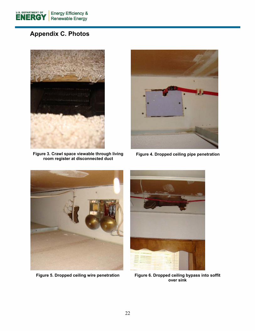
Appendix C. Photos
Figure 3. Crawl space viewable through living
room register at disconnected duct
Figure 4. Dropped ceiling pipe penetration
Figure 5. Dropped ceiling wire penetration
Figure 6. Dropped ceiling bypass into soffit
over sink
23
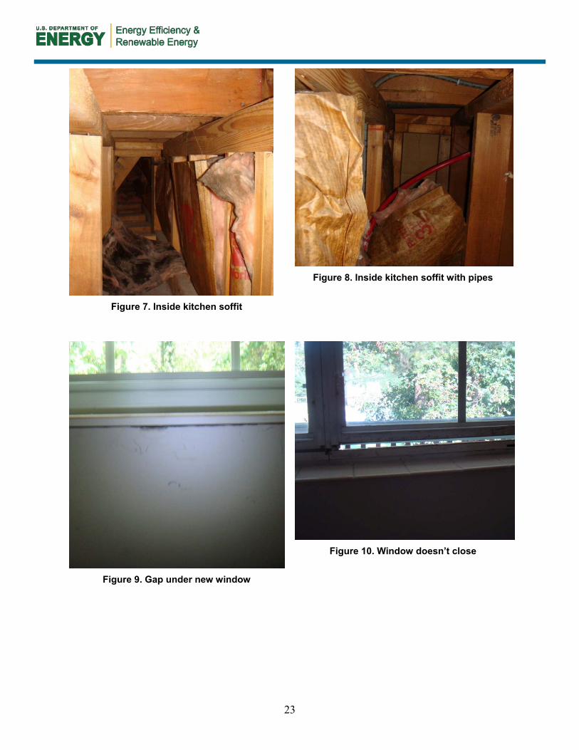
Figure 7. Inside kitchen soffit
Figure 8. Inside kitchen soffit with pipes
Figure 9. Gap under new window
Figure 10. Window doesn’t close

24
Figure 11. Window leakage
Figure 12. Semi‐sealed dropped ceiling with
pipe
Figure 13. Semi‐sealed dropped ceiling opening
Figure 14. Semi‐sealed dropped ceiling
25
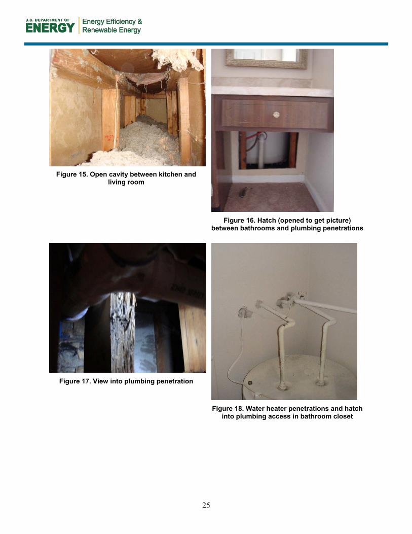
Figure 15. Open cavity between kitchen and
living room
Figure 16. Hatch (opened to get picture)
between bathrooms and plumbing penetrations
Figure 17. View into plumbing penetration
Figure 18. Water heater penetrations and hatch
into plumbing access in bathroom closet

26
Table 12. Pictures from 2030 Bedford Unit 8
Figure 19. Cavity between units under tub
Figure 20. Window leakage
Figure 21. Behind dropped ceiling
Figure 22. Open cavities through dropped
ceiling

27
Figure 23. Open chase through dropped ceiling
Figure 24. Plumbing penetrations
Figure 25. Plumbing penetrations into attic
28
Appendix D. Specifications
GENERAL
1.1 SUMMARY
A. This specification includes the following:
1. Air sealing techniques, priorities and products specific to the Yorktowne Apartments air sealing project.
B. Related Sections
1. NOT USED
1.2 DEFINITIONS
A. Air Barrier: An element or assembly which controls air movement into and out of a structure
1.3 PERFORMANCE REQUIREMENTS
A. Air Sealing Assemblies shall be capable of accommodating substrate movement, joints and intersections, construction material, and other transitions without deterioration or air leakage exceeding specified limits.
1.4 ACTION SUBMITTALS
A. Product Data: Include manufacturer’s written instructions for evaluating, preparing, and treating substrate, technical data, and tested physical and performance properties of air barrier.
B. Shop Drawings: Include details for substrate joints and cracks, penetrations, voids, and attic assemblies.
1.5 INFORMATIONAL SUBMITTALS
A. NOT USED
1.6 QUALITY ASSURANCE
A. Applicator Qualifications: Installer is to be experienced in applying air barrier materials similar in material, design, and extent to those indicated for this Project, whose work has resulted in applications with a record of successful performance.
B. Blower Door Testing: Identify location of Air Barrier material throughout the unit to be sealed. Test all units for leakage to outside before beginning any air sealing strategy. Pressurize to 50 Pa and record leakage, or extrapolate to leakage at

29
CFM50. After completing air sealing tasks, provide follow‐up blower door test to assure that owner’s reduction requirement has been met.
C. Conferences: Review air sealing requirements including surface preparation, substrates, curing/drying periods, installation procedures, repairs and protection. Coordinate air sealing strategies and sequencing with HVAC contractor to ensure that no work is duplicated or neglected.
1.7 DELIVERY, STORAGE, AND HANDLING
A. Store liquid materials in their original undamaged packages in a clean, dry, protected location and within temperature range required by product manufacturer. Remove and replace liquid materials that cannot be applied within their stated shelf life Protect stored materials from sunlight
1.8 PROJECT CONDITIONS
A. Environmental Limitations: Apply air sealing materials within the range of ambient temperatures recommended by the product manufacturer.
PRODUCTS
1.9 RIGID AIR BARRIER MATERIALS
A. Gypsum Wall Board
B. Oriented Strand Board
C. Rigid Faced Insulation Board
1.10 POLYURETHANE SPRAY FOAM
A. Single-Part Spray Foam (Expanding and non-expanding)
B. Two-Part Spray Foam
1.11 CAULKS AND JOINT SEALANTS
A. Silicone or Polyurethane Caulk
1.12 FLUID APPLIED AIR BARRIERS
A. Liquid Air Barrier Membranes and Mastics
1.13 AUXILARY MATERIALS
A. General: Employ auxiliary materials recommended by manufacturer for intended use and compatible with substrates and membranes.
30
B. Transition reinforcing strips: Glass fiber mesh tapes approved by Air Barrier Manufacturer at voids with spans greater than ¼”.
C. Backer Rod: Compressible foam backer rod to be installed before applying sealants and mastics at areas with cracks larger than ¼”.
D. Mechanical Fasters: Provide wood or gypsum board screws as needed of length necessary to securely fasten rigid air barrier materials to structure.
E. Weatherstripping: Provide flexible weatherstripping around doors and attic accesses to reduce air infiltration
EXECUTION
1.14 EXAMINATION
A. Examine substrates areas and conditions, with installer present, for compliance with requirements and other conditions affecting performance.
1. Verify that substrates are sound and free of oil, grease, dirt, excess mortar and other contaminants.
1.15 SURFACE PREPARATION
A. Provide clean, dust-free, and dry substrate for air barrier application.
B. Mask off adjoining surfaces to be covered by air barrier to prevent spillage and overspray in the visible living area.
C. At changes in substrate plane, apply sealant or mastic at sharp corners and edges to form a smooth transition from one place to another
D. Where rigid materials are to be fastened, provide clean adjacent edges to create a flush or near flush (within ¼ in.) transition between existing and new rigid materials. Cut away jagged edges to create a regular surface before inserting patches. Ensure that structural base for rigid air barrier material will adequately support the material to be fastened. Cut patches to dimensions t minimize unnecessary use of backer rod, tapes, and strips.
1.16 PRIORITY
A. General: Air Sealing tasks are to be prioritized to maximize results over time. Seal largest areas of compromised air barrier first, and then work toward locations with smaller air leaks.
B. Primary Areas
1. Missing Sheathing: Install/repair air barrier above dropped ceilings in kitchens. Provide and install rigid air barriers and sealing products to complete airtight

31
assembly above dropped ceiling. Prepare surfaces to receive rigid air barrier panels, patches, and plugs. Mechanically fasten oriented strand board or gypsum wall board to structure and seal all joints and intersections with joint sealants or fluid applied membranes. Seal existing and newly installed rigid air barriers to make a complete air barrier.
2. Plumbing, Electrical, Mechanical penetrations: Seal and make airtight all penetrations through the air barrier, including (not limited to): Plumbing penetrations around pipes, drains and vents; Mechanical penetrations around supply ducts, returns, and exhaust fans; Electrical penetrations surrounding outlets, conduits and wiring. For air leaks around penetrations which are greater than ¼ in., rigid plugs or mesh transition reinforcement strips should be used to bridge gaps and allow for full sealing of penetrations.
3. HVAC Closets: Completely seal perimeter and voids in HVAC closets with caulk to ensure that no air leaks between outside and mechanically depressurized closets.
4. Other voids: Air seal all other voids present in vertical and horizontal air barrier assemblies using appropriate products to complete an airtight boundary.
C. Secondary Leakage Areas
1. Attic access: Provide and install perimeter weatherstripping to reduce air infiltration around attic hatch.
2. Ceiling‐to‐wall and floor‐to‐wall: Provide and install air sealing materials to create an airtight boundary between the floor and ceiling surfaces and the vertical walls.
3. Exterior Doors: Provide and install flexible weatherstripping to ensure a tight seal around all exterior doors. Ensure that exterior doors fit snugly in their openings and adjust placement to maintain airtightness on all sides.
4. Windows: Apply sealants and necessary backers to ensure that window installation forms a tight air barrier. Be sure that sealant connects window to wall air barrier. Windows generally have a primary exterior weather barrier that often does not serve as an air barrier Electrical Fixtures: Apply sealant to all fixtures which penetrate the air barrier, or completely remove fixture and repair air barrier.
1.17 FIELD QUALITY CONTROL
A. Testing Agency: Owner may engage a qualified testing agency to perform random inspections and air leakage testing, and prepare reports detailing the findings.
B. Inspection: Installation and products are subject to inspection for compliance with the owner’s and manufacturer’s requirements. Inspections may include:
32
1. Continuity of repairs has been achieved with no voids, gaps, or holes unsealed.
2. Laps in transitions have been layered in the correct direction, or mastic has been applied to exposed edges.
3. Sealants and strips have been firmly adhered or fastened to the substrate material
4. Compatibility of materials.
5. All penetrations have been sealed.
C. Testing: Provide evidence of reduced air leakage using blower door testing and smoke visualization inspection.
D. Remove and replace deficient air sealing components and retest.
1.18 CLEANING AND PROTECTION
A. Clean spills, stains, and soiling from construction that would be exposed in the completed work using cleaning agents and procedures recommended by the manufacturer of the affected construction.
B. Remove masking materials after installation.
33
Appendix E. Air Sealing Instructions
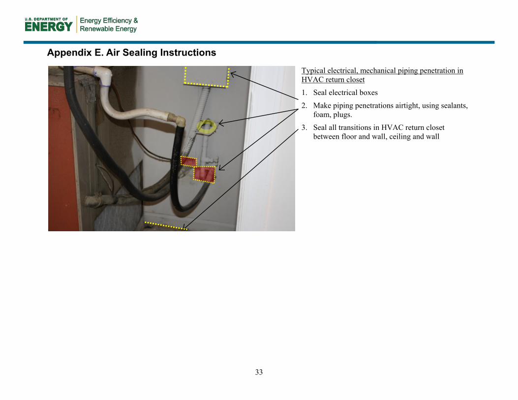
Typical electrical, mechanical piping penetration in HVAC return closet
1. Seal electrical boxes
2. Make piping penetrations airtight, using sealants, foam, plugs.
3. Seal all transitions in HVAC return closet between floor and wall, ceiling and wall

34
Typical electrical fixture penetration
1. Seal can lights and ceiling fan to air barrier or remove completely and repair air barrier. Seal entire perimeter of fan. Air leakage within the fixture assemblies may require that airtight enclosures be installed on the attic side, and then sealed to the ceiling air barrier.
2. Seal intersection of HVAC supply duct with ceiling air barrier
35
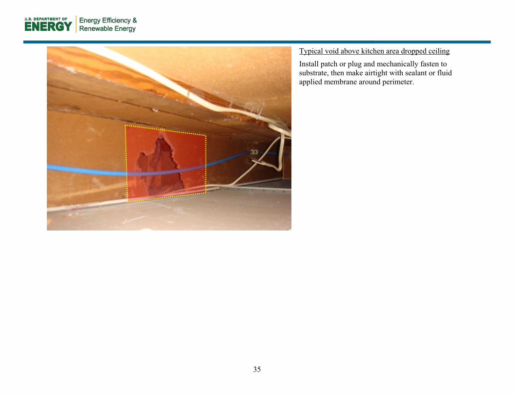
Typical void above kitchen area dropped ceiling
Install patch or plug and mechanically fasten to substrate, then make airtight with sealant or fluid applied membrane around perimeter.

36
Typical access void behind tub in bathroom
Install patch or plug and mechanically fasten to substrate, then make airtight with sealant or fluid applied membrane around perimeter.
37
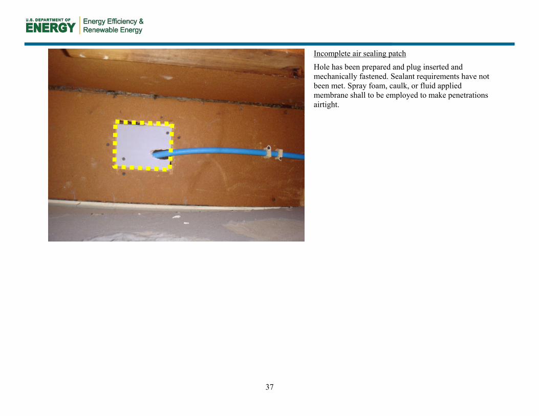
Incomplete air sealing patch
Hole has been prepared and plug inserted and mechanically fastened. Sealant requirements have not been met. Spray foam, caulk, or fluid applied membrane shall to be employed to make penetrations airtight.

38
Typical unsealed duct penetration
Apply spray foam or sealant/membrane with transition strips around HVAC penetration to make airtight.

39
Typical attic scuttle
Install weatherstripping to create snug seal between ceiling and attic scuttle.

40
Unsealed HVAC return
Install return duct between air handler and grill (HVAC scope).
Make airtight with sealant or membrane.

41
Typical kitchen area above dropped ceiling
Seal attic penetrations for light fixture above dropped ceiling, or remove fixture entirely and repair air barrier.
Seal drywall and ceiling lid to structure with a continuous bead of caulk or joint sealant.

42
HVAC duct penetration through air barrier
Install sealants or membranes with backing rod or transition strips as necessary to make duct penetration airtight.

43
Typical unsealed plumbing penetration under sink
Air seal between the plumbing penetration and the GWB air barrier using continuous beads of spray foams or fluid membrane with transition strips.
44
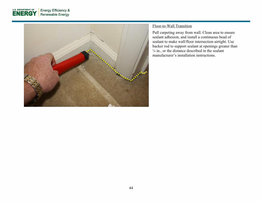
Floor-to-Wall Transition
Pull carpeting away from wall. Clean area to ensure sealant adhesion, and install a continuous bead of sealant to make wall/floor intersection airtight. Use backer rod to support sealant at openings greater than ¼ in., or the distance described in the sealant manufacturer’s installation instructions.
45
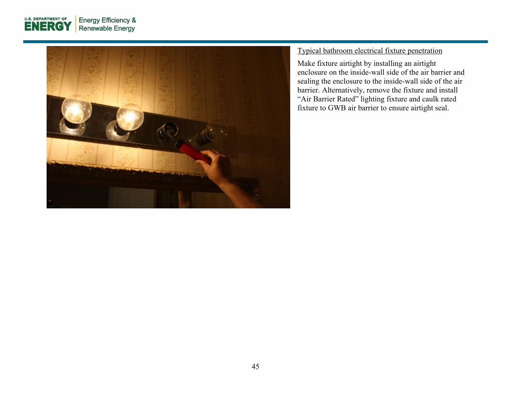
Typical bathroom electrical fixture penetration
Make fixture airtight by installing an airtight enclosure on the inside-wall side of the air barrier and sealing the enclosure to the inside-wall side of the air barrier. Alternatively, remove the fixture and install “Air Barrier Rated” lighting fixture and caulk rated fixture to GWB air barrier to ensure airtight seal.
DOE/GO-102012-3583 ▪ October 2012
Printed with a renewable-source ink on paper containing at least 50% wastepaper, including 10% post-consumer waste.


