80
Q UICK C OUPLING R EFERENCE G UIDE Air-Oil Systems, Inc. www.airoil.com

QUICK COUPLING REFERENCE GUIDEAi
r-Oil Sy
stems,
Inc.
www.a
iroil.co
m

Air-O
il Sy
stems,
Inc.
www.a
iroil.co
m

H A N S E N C O U P L I N G S3
A Letter from the President To Our Valued Customers: Tuthill Coupling Group’s philosophy is to understand our customer’s values and develop
products and process to exceed their expectations. Our relentless emphasis on employee
development results in an organization that is nimble and can execute by delivering quality
products backed by great customer service. We believe, having the best people focused
on delivering value to the customer, will keep us in the forefront of the quick connect cou-
pling industry. As the innovator of quick disconnect couplings, for over 90 years, the Hansen brand has
earned the reputation for top quality. Evidenced in this expanded catalog, Hansen Couplings
are now available in a multitude of sizes and materials. Even more offerings are showcased
on our website www.tuthill.com including many of our European style offerings. Tuthill Cou-
pling Group has one of the broadest product lines available in the industry.
Our quick connect couplings are backed by an experienced team of professionals with com-
plete technical resources at your disposal. Engineers work directly with customers
to find the right coupling for their application, often improving their existing systems and
making the critical difference for demanding requirements. Our ability to design and
produce special products for original equipment manufacturers is a core strength.
While we have been recognized by industry groups, trade journals, and customers
for having excellent manufacturing capabilities, coupled with a zeal for continuous
improvement, we are never content with anything less than perfection. It is true that
the Hansen Coupling brand has a remarkable history, yet with our team of dedicated em-
ployees, the future is even more exciting. Sincerely,
Brett Jaffe PresidentAi
r-Oil Sy
stems,
Inc.
www.a
iroil.co
m

By focusing exclusively on couplings, Tuthill Coupling Group has achieved a competitive edge in providing the world’s best and most complete line of quick disconnect couplings. The quick connect/disconnect coupling was first developed and manufac-tured by Hansen Manufacturing Company, founded in 1915 by Fred Hansen. Since then, the Hansen coupling has become the industry standard for all quick connect/disconnect couplings. Tuthill Coupling Group designs, manufactures and distributes a broad range of couplings in brass, steel, stainless steel and plastic. These products are used to quickly connect and dis-connect a wide variety of fluids and gases, especially air and hydraulic oil. The bodies, sleeves and plugs are manufactured by Tuthill Coupling Group, then hardened and plated as required, and then assembled with other components such as stainless steel balls, seals and valves. Hansen Couplings are available in over 3,000 configurations, which are marketed to end users and original equipment manufacturers all over the world. Since Hansen was purchased by Tuthill Corporation in 1979, it has maintained a steady pattern of growth. Tuthill Coupling Group will continue to be a major factor in this market by offering a com-prehensive range of products, which are thoroughly researched, carefully designed, and precision manufactured. Our products are widely distributed through an increasingly strong network of worldwide distributors that are well versed in the engineered fluid power product needs of our customers.
H A N S E N C O U P L I N G S4
Air-O
il Sy
stems,
Inc.
www.a
iroil.co
m

H A N S E N C O U P L I N G S5
PRODUCT ENGINEERINGMany designs created as full spe-cials have now become the world standard. Tuthill Coupling Group has provided full service solutions, dedicated exclusively to quick dis-connect applications. Tuthill Cou-pling Group’s engineers develop new products and modify designs of existing products using the latest Computer Aided Design programs. PRODUCT DESIGN & PROTOTYPE Tuthill Coupling Group’s state of the art prototype development lab offers a unique environment for cycle testing, pressure testing and full model shop manufacturing. Quality controlled stan-dards insure complete success on new and standard product designs. Tuthill Coupling Group products maintain a constantly high level of quality and dependability through extensive product testing and evaluation.
ISO 9001:2000
Certificate No. 006888
QUALITY CONTROLTuthill Coupling Group’s Quality Management System is registered to rigid ISO 9001:2000 standards. The highest quality raw materials and components are machined and meticulously assembled. Care is taken to record and maintain specific tolerances in the day-to-day production of our products through constant monitoring and calibrating of our production equipment.
CUSTOMER SERVICEYour highly trained inside sales representative is equipped to aid customers in product selection and to ensure your order is processed quickly, efficiently and accurately. Our customer fulfillment staff works closely with their corresponding outside sales individual to ensure consistent personalized assistance from the time an order is placed to the final as-sembly point of the product. Our distributors are strategically located throughout the world to provide prompt delivery of Hansen Couplings. Tuthill Coupling Group’s goal is to provide our customers with the best service and technical support available.
Air-O
il Sy
stems,
Inc.
www.a
iroil.co
m
6
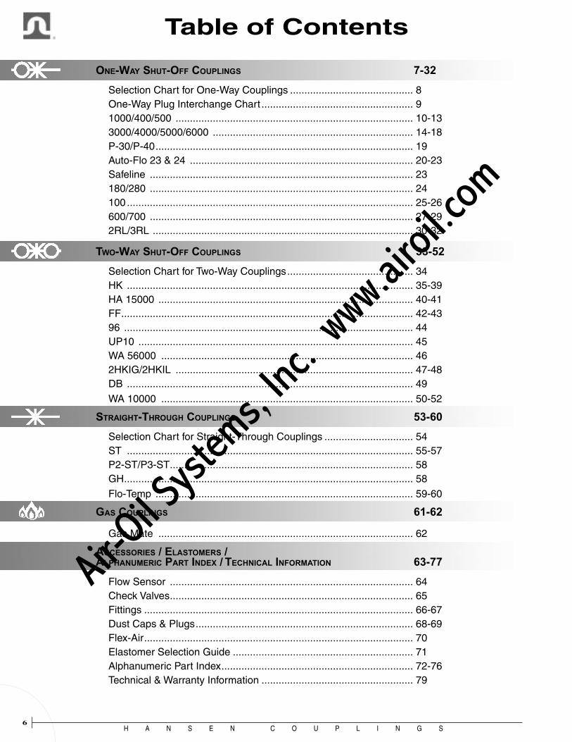
ONE-WAY SHUT-OFF COUPLINGS 7-32
Selection Chart for One-Way Couplings ........................................... 8 One-Way Plug Interchange Chart ..................................................... 9 1000/400/500 ................................................................................... 10-13 3000/4000/5000/6000 ...................................................................... 14-18 P-30/P-40 .......................................................................................... 19 Auto-Flo 23 & 24 .............................................................................. 20-23 Safeline ............................................................................................ 23 180/280 ............................................................................................ 24 100 .................................................................................................... 25-26 600/700 ............................................................................................ 27-29 2RL/3RL ........................................................................................... 30-32
TWO-WAY SHUT-OFF COUPLINGS 33-52
Selection Chart for Two-Way Couplings ............................................ 34 HK .................................................................................................... 35-39 HA 15000 ......................................................................................... 40-41 FF ...................................................................................................... 42-43 96 ..................................................................................................... 44 UP10 ................................................................................................ 45 WA 56000 ........................................................................................ 46 2HKIG/2HKIL ................................................................................... 47-48 DB .................................................................................................... 49
WA 10000 ........................................................................................ 50-52
STRAIGHT-THROUGH COUPLINGS 53-60
Selection Chart for Straight-Through Couplings ............................... 54 ST .................................................................................................... 55-57 P2-ST/P3-ST ..................................................................................... 58 GH ..................................................................................................... 58
Flo-Temp .......................................................................................... 59-60
GAS COUPLINGS 61-62
Gas Mate ......................................................................................... 62
ACCESSORIES / ELASTOMERS / ALPHANUMERIC PART INDEX / TECHNICAL INFORMATION 63-77
Flow Sensor ..................................................................................... 64 Check Valves ..................................................................................... 65 Fittings .............................................................................................. 66-67 Dust Caps & Plugs ............................................................................ 68-69 Flex-Air .............................................................................................. 70 Elastomer Selection Guide ............................................................... 71 Alphanumeric Part Index ................................................................... 72-76 Technical & Warranty Information ..................................................... 79
Table of Contents
H A N S E N C O U P L I N G S
Air-O
il Sy
stems,
Inc.
www.a
iroil.co
m

H A N S E N C O U P L I N G S7
ON
E-W
AY
7
ONE-WAY COUPLINGS
Air-O
il Sy
stems,
Inc.
www.a
iroil.co
m

H A N S E N C O U P L I N G S8
ON
E-W
AY
Coupling Series Page
1000 11 ● ● ● ● ● ● ● ● ●
400 12 ● ● ● ● ● ● ● ● ●
500 13 ● ● ● ● ● ● ●
3000 15 ● ● ● ● ● ● ● ●
4000 16 ● ● ● ● ● ● ● ●
5000 17 ● ● ● ● ● ● ●
6000 18 ● ● ● ● ● ● ●
P-30 19 ● ● ● ● ●
P-40 19 ● ● ● ● ●
Auto-Flo 23 21 ● ● ● ● ● ● ●
Auto-Flo 24 21 ● ● ● ● ●
Safeline 23 ● ● ● ● ● ● ●
180/280 24 ● ● ● ● ● ●
100 25 ● ● ● ● ● ● ●
600/700 27 ● ● ● ● ● ● ●
2-RL 31 ● ● ● ● ● ▼ ● ●
3-RL 32 ● ● ● ● ● ▼ ● ●
▼ Sleeve lock is automatic with RL couplings.
MA
NU
AL
CO
NN
EC
T
PU
SH
-TO
-CO
NN
EC
T
SA
FE
TY
CO
UP
LIN
G
IND
US
TR
IAL
INT
ER
CH
AN
GE
AR
O 2
10
TR
U-F
LA
TE
CE
JN 3
20/R
EC
TU
S 2
5
HA
NS
EN
RL
ST
YL
E
HA
NS
EN
UN
IQU
E D
ES
IGN
1/8
INC
H
1/4
INC
H
3/8
INC
H
1/2
INC
H
3/4
INC
H
AL
UM
INU
M
BR
AS
S
ST
EE
L (
Zin
c/C
hro
mat
e F
inis
h)
STA
INL
ES
S S
TE
EL
PL
AS
TIC
(A
ceta
l)
BA
LL
LO
CK
PIN
LO
CK
RIN
G L
OC
K
PL
AS
TIC
FIN
GE
RS
SL
EE
VE
LO
CK
SE
AL
MA
TE
RIA
LS
(V
ario
us)
DU
ST
CA
P (
Vin
yl)
Coupling Style
Interchange Body SizeBody
MaterialLocking
MechanismOptions
Contents and Selector Chart
Air-O
il Sy
stems,
Inc.
www.a
iroil.co
m

H A N S E N C O U P L I N G S9
ON
E-W
AY
The plug profiles shown below are actual size. This chart can be used to help select Hansen one-way couplings. Industrial Interchange plugs of the appropriate size connect with the following Series sockets: 1000, 400, 500, 3000, 4000, 5000, 6000, Auto-Flo 23, P-30, P-40 and SVS. ARO 210 and Tru-Flate 1/4” plugs connect with Auto-Flo 23 sockets. Tru-Flate 3/8” plugs connect with Series 400 sockets. Auto-Flo 24 plugs interchange with CEJN 320 and Rectus 24. The bottom row of this chart shows unique Hansen plug designs.
ONE-WAY PLUGInterchange Chart
ARO 210 Tru-Flate Tru-Flate Auto-Flo 24
100 600 700 2RL 3RL
Industrial Interchange
180/280
Air-O
il Sy
stems,
Inc.
www.a
iroil.co
m

H A N S E N C O U P L I N G S10
ON
E-W
AY
Industrial Interchange Ball Lock Quick-Connect Couplings de-signed for compressed air, gases, and liquids. Body sizes are 1/4”, 3/8” and 1/2”.
Rated PressureSeries Size PSI BAR
1000 1/4” 2,000 138 400 3/8” 1,000 69 500 1/2” 500 35
Flow Capacity Series † Ac 1000 28 400 45 500 72
NOTE: Series 400 operating pressure is 150 psi when connected to Tru-Flate Interchange plug.
† Air flow (scfm) with 5 psi pressure drop and 100 psig inlet pressure
Features
• Ball lock
• Manual operation
• Rugged, reliable
• 1/4” and 1/2” sockets accept MIL-C-4109 plugs
• Optional sleeve lock prevents accidental disconnection
• Optional seal and valve materials available
• Optional stainless steel socket (Series 1000 only)
• Series 400 sockets accept Tru-Flate Interchange plugs and Industrial Interchange plugs
Standard Materials• Socket - Brass Body - Nickel Plated Steel Sleeve - Zinc Plated Steel Valve - Buna-N (Nitrile) Seal - Stainless Steel Springs - Stainless Steel Locking Balls
• Plug - Zinc Plated Case-Hardened Steel (All Sizes) - Brass (All Sizes) - Stainless Steel (Series 1000)Accessories • Dust caps and dust plugs (See page 68)
Series 1000/400/500Industrial Interchange
Air-O
il Sy
stems,
Inc.
www.a
iroil.co
m
H A N S E N C O U P L I N G S11
ON
E-W
AY
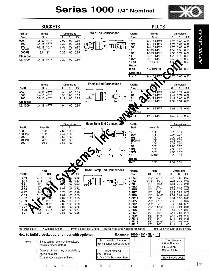
Male End Connections
Female End Connections
Hose Stem End Connections
Hose Clamp End Connections
Part No. Thread Dimensions Brass Size A B HEX900 1/8-27 NPTF 2.07 1.00 0.69 1100 1/4-18 NPTF 2.22 1.00 0.69 1300 3/8-18 NPTF 2.22 1.00 0.69 1000-43 7/16–20* 2.16 1.00 0.69 1000-63 5/8–18* 2.29 1.00 0.69StainlessLL-1100 1/4-18 NPTF 2.22 1.00 0.69
Part No. Thread Dimensions Steel Size C D HEX
10 1/4-18 NPTF 1.75 0.65 0.56 10C§ 1/4-18 NPTF 1.75 0.65 0.56 10G† 1/4-18 NPTF 1.75 0.65 0.56 12 1/8-27 NPTF 1.59 0.58 0.50 12G† 1/8-27 NPTF 2.38 0.77 0.69 14 3/8-18 NPTF 1.75 0.79 0.69 14G† 3/8-18 NPTF 2.53 0.77 0.69 10-43 7/16-20* 1.69 0.58 0.50BrassB-10 1/4-18NPTF 1.75 0.64 0.56StainlessLL-10 1/4-18 NPTF 1.75 0.65 0.56
Thread Dimensions Part No. Size A B HEX
800 1/8-27 NPTF 1.91 1.00 0.69 1000 1/4-18 NPTF 1.91 1.00 0.69 1200 3/8-18 NPTF 2.19 1.00 0.75StainlessLL-1000 1/4-18 NPTF 1.91 1.00 0.69
Part No. Thread Dimensions Steel Size C D HEX
11 1/4-18 NPTF 1.63 0.79 0.69 11G† 1/4-18 NPTF 2.44 0.77 0.69 13 1/8-27 NPTF 1.47 0.65 0.56 15 3/8-18 NPTF 1.69 0.94 0.81Brass11B 1/4-18 NPTF 1.63 0.78 0.69StainlessLL-11 1/4-18 NPTF 1.63 0.79 0.69
Dimensions Part No. Hose I.D. A B 1600 1/4” 2.66 1.00 1600P‡ 1/4” 2.44 1.00 1700 3/8” 2.65 1.00 1700P‡ 3/8” 2.54 1.00 1800 5/16” 2.66 1.00
Part No. Dimensions Steel Hose I.D. C D
16 1/4” 2.22 0.50 16G† 1/4” 2.97 0.77 16P‡ 1/4” 2.00 0.69 16PG† ‡ 1/4” 2.75 0.77 17 3/8” 2.31 0.50 17G† 3/8” 2.96 0.77 17P‡ 3/8” 2.06 0.87 17PG† ‡ 3/8” 2.85 0.87 18 5/16” 2.22 0.50BrassB-17 3/8” 2.31 0.50
How to build a socket part number with options: Example: 1000 - BV - SL - 143
Standard Part Number from Socket Tables Above
Valve Material:BV = Brass LLV = 303 Stainless Steel
Seal Material:138 = Silicone 143 = Viton 192 = EPDM
SL = Sleeve Lock
Notes: 1) Some part numbers may be subject to minimum order quantities.
2) Options not shown may be available by special quotation. Consult your Hansen distributor.
Part No. Hose Dimensions Steel I.D. O.D. C D HEX3-PA0 3/16” 7/16” 2.25 0.63 0.56 3-PA3 3/16” 1/2” 2.25 0.70 0.63 3-PB1 1/4” 15/32” 2.31 0.70 0.63 3-PB3 1/4” 1/2” 2.31 0.70 0.63 3-PB5 1/4” 9/16” 2.31 0.77 0.69 3-PB7 1/4” 5/8” 2.31 0.84 0.75 3-PB9 1/4” 11/16” 2.31 0.91 0.81 3-PB11 1/4” 3/4” 2.31 0.98 0.88 3-PC5 5/16” 9/16” 2.38 0.77 0.69 3-PC7 5/16” 5/8” 2.38 0.84 0.75 3-PC9 5/16” 11/16” 2.38 0.91 0.81 3-PD5 3/8” 9/16” 2.44 0.77 0.69 3-PD7 3/8” 5/8” 2.44 0.84 0.75 3-PD9 3/8” 11/16” 2.44 0.91 0.81 3-PD11 3/8” 3/4” 2.44 1.98 0.88 3-PD13 3/8” 13/16” 2.44 1.05 0.94 3-PD15 3/8” 7/8” 2.44 1.12 1.00
SOCKETS PLUGS
*45° Male Flare §With Ball Check †With Bleeder Ball Check – Reduces hose whip when disconnecting. ‡For use with push-on style hose.
Hose Dimensions Part No. I.D. O.D. A B HEX1-SA0 3/16” 7/16” 2.69 1.00 0.56 1-SA3 3/16” 1/2” 2.69 1.00 0.63 1-SB1 1/4” 15/32” 2.75 1.00 0.63 1-SB3 1/4” 1/2” 2.75 1.00 0.63 1-SB5 1/4” 9/16” 2.75 1.00 0.69 1-SB7 1/4” 5/8” 2.75 1.00 0.75 1-SC5 5/16” 9/16” 2.82 1.00 0.69 1-SC7 5/16” 5/8” 2.82 1.00 0.75 1-SC9 5/16” 11/16” 2.82 1.00 0.81 1-SD5 3/8” 9/16” 2.88 1.00 0.69 1-SD7 3/8” 5/8” 2.88 1.00 0.75 1-SD9 3/8” 11/16” 2.88 1.00 0.81 1-SD11 3/8” 3/4” 2.88 1.00 0.88
Series 1000 1/4” Nominal
Air-O
il Sy
stems,
Inc.
www.a
iroil.co
m

H A N S E N C O U P L I N G S12
ON
E-W
AY
Female End Connections
Male End Connections
Hose Clamp End Connections
Hose Stem End Connections
Part No. Thread Dimensions Steel Size C D HEX31AP-25M 1/4-18 NPTF 1.85 0.72 0.63 31AP-37M 3/8-18 NPTF 1.85 0.79 0.69
Thread Dimensions Part No. Size A B HEX410-A 1/8-27 NPTF 2.20 1.13 0.88 410 1/4-18 NPTF 2.35 1.13 0.88 430 3/8-18 NPTF 2.35 1.13 0.88 450 1/2-14 NPTF 2.54 1.13 0.88
Part No. Thread Dimensions Steel Size C D HEX38 1/8-27 NPTF 1.72 0.72 0.63 40 1/4-18 NPTF 1.88 0.72 0.63 40G† 1/4-18 NPTF 2.65 0.77 0.69 42 3/8-18 NPTF 1.88 0.79 0.69 42G† 3/8-18 NPTF 2.65 0.77 0.69 44 1/2-14 NPTF 2.09 1.01 0.88BrassB-40 1/4-18 NPTF 1.88 0.70 0.63 B-42 3/8-18 NPTF 1.88 0.77 0.69
Hose Dimensions Part No. I.D. O.D. A B HEX40-SB3 1/4” 1/2” 2.92 1.13 0.63 40-SB7 1/4” 5/8” 2.92 1.13 0.75 40-SD7 3/8” 5/8” 3.04 1.13 0.75 40-SD9 3/8” 11/16” 3.04 1.13 0.81 40-SD11 3/8” 3/4” 3.04 1.13 0.88 40-SD13 3/8” 13/16” 3.04 1.13 0.94 40-SP13 1/2” 13/16” 3.67 1.13 0.94 40-SP15 1/2” 7/8” 3.67 1.13 1.00 40-SP17 1/2” 15/16” 3.67 1.13 1.06 40-SP19 1/2” 1” 3.67 1.13 1.13
Part No. Hose Dimensions Steel I.D. O.D. C D HEX 4-PB1 1/4” 15/32” 2.44 0.70 0.63 4-PB3 1/4” 1/2” 2.44 0.70 0.63 4-PB5 1/4” 9/16” 2.44 0.77 0.69 4-PB7 1/4” 5/8” 2.44 0.84 0.75 4-PB9 1/4” 11/16” 2.44 0.91 0.81 4-PB11 1/4” 3/4” 2.44 0.98 0.88 4-PD5 3/8” 9/16” 2.56 0.77 0.69 4-PD7 3/8” 5/8” 2.56 0.84 0.75 4-PD9 3/8” 11/16” 2.56 0.91 0.81 4-PD11 3/8” 3/4” 2.56 0.98 0.88 4-PD13 3/8” 13/16” 2.56 1.05 0.94 4-PD15 3/8” 7/8” 2.56 1.12 1.00 4-PP13 1/2” 13/16” 3.25 1.05 0.94 4-PP15 1/2” 7/8” 3.25 1.12 1.00 4-PP17 1/2” 15/16” 3.25 1.19 1.06 4-PP19 1/2” 1” 3.25 1.26 1.13
Thread Dimensions Part No. Size A B HEX400-A 1/8-27 NPTF 2.10 1.13 0.88 400 1/4-18 NPTF 2.10 1.13 0.88 420 3/8-18 NPTF 2.35 1.13 0.88 440 1/2-14 NPTF 2.62 1.13 1.00
Part No. Thread Dimensions Steel Size C D HEX41 1/4-18 NPTF 1.63 0.79 0.69 41G† 1/4-18 NPTF 2.56 0.77 0.69 43 3/8-18 NPTF 1.81 0.94 0.81 43G† 3/8-18 NPTF 2.62 0.84 0.75 45 1/2-14 NPTF 2.06 1.15 1.00BrassB-43 3/8-18 NPTF 1.81 0.91 0.81
Dimensions Part No. Hose I.D. A B 4004 1/4” 2.82 1.13 4050 5/16” 2.82 1.13 4006 3/8” 2.82 1.13 4008 1/2” 2.82 1.13
Part No. Dimensions Steel Hose I.D. C D 404 1/4” 2.34 0.63 406 3/8” 2.34 0.63 408 1/2” 2.34 0.81 BrassB-406 3/8” 2.34 0.63
†With Bleeder Ball Check – Reduces hose whip when disconnecting.
Part No. Thread Dimensions Steel Size C D HEX31AP-25F 1/4-18 NPTF 1.60 0.79 0.69 31AP-37F 3/8-18 NPTF 1.78 0.94 0.81
How to build a socket part number with options: Example: 400 - BV - SL - 143
Standard Part Number from Socket Tables Above
Valve Material:BV = Brass LLV = 303 Stainless Steel
Seal Material:138 = Silicone 143 = Viton 192 = EPDM
SL = Sleeve Lock
Notes: 1) Some part numbers may be subject to minimum order quantities.
2) Options not shown may be available by special quotation. Consult your Hansen distributor.
SOCKETS PLUGS
Series 400 3/8” Nominal
All dimensions in inches.
Air-O
il Sy
stems,
Inc.
www.a
iroil.co
m

H A N S E N C O U P L I N G S13
ON
E-W
AY
Male End Connections
Hose Clamp End Connections
Female End Connections
Hose Stem End Connections
Thread Dimensions Part No. Size A B HEX501 1/4-18 NPTF 2.77 1.19 1.00 510 3/8-18 NPTF 2.78 1.19 1.00 530 1/2-14 NPTF 2.97 1.19 1.00 550 3/4-14 NPTF 2.97 1.19 1.06
Part No. Thread Dimensions Steel Size C D HEX50 1/4-18 NPTF 2.25 0.79 0.69 50G† 1/4-18 NPTF 2.90 0.98 0.88 52 3/8-18 NPTF 2.25 0.87 0.75 52G† 3/8-18 NPTF 2.90 0.98 0.88 54 1/2-14 NPTF 2.44 1.01 0.88 54G† 1/2-14 NPTF 3.09 0.98 0.88 56 3/4-14 NPTF 2.50 1.23 1.06 56G† 3/4-14 NPTF 3.14 1.19 1.06BrassB-52 3/8-18 NPTF 2.25 0.70 0.63 B-54 1/2-14 NPTF 2.44 0.77 0.88
Hose Dimensions Part No. I.D. O.D. A B HEX50-SD7 3/8” 5/8” 3.49 1.19 0.75 50-SD13 3/8” 13/16” 3.49 1.19 0.94 50-SP13 1/2” 13/16” 4.09 1.19 0.94 50-SP15 1/2” 7/8” 4.09 1.19 1.00 50-SP17 1/2” 15/16” 4.09 1.19 1.06 50-SP19 1/2” 1” 4.09 1.19 1.13 50-SR23 3/4” 11/8” 4.22 1.19 1.25 50-SR25 3/4” 13/16” 4.22 1.19 1.31 50-SR27 3/4” 11/4” 4.22 1.19 1.38
Part No. Hose Dimensions Steel I.D. O.D. C D HEX5-PB1 1/4” 15/32” 2.81 0.70 0.63 5-PB3 1/4” 1/2” 2.81 0.70 0.63 5-PB5 1/4” 9/16” 2.81 0.77 0.69 5-PB7 1/4” 5/8” 2.81 0.84 0.75 5-PD5 3/8” 9/16” 2.94 0.77 0.69 5-PD7 3/8” 5/8” 2.94 0.84 0.75 5-PD9 3/8” 11/16” 2.94 0.91 0.81 5-PD11 3/8” 3/4” 2.94 0.98 0.88 5-PD13 3/8” 13/16” 2.94 1.05 0.94 5-PD15 3/8” 7/8” 2.94 1.12 1.00 5-PP13 1/2” 13/16” 3.62 1.05 0.94 5-PP15 1/2” 7/8” 3.62 1.12 1.00 5-PP17 1/2” 15/16” 3.62 1.19 1.06 5-PP19 1/2” 1” 3.62 1.26 1.13 5-PR23 3/4” 11/8” 3.75 1.40 1.25 5-PR25 3/4” 13/16” 3.75 1.47 1.31 5-PR27 3/4” 11/4” 3.75 1.54 1.38
Thread Dimensions Part No. Size A B HEX500-A 1/4-18 NPTF 2.72 1.19 1.00 500 3/8-18 NPTF 2.78 1.19 1.00 520 1/2-14 NPTF 3.06 1.19 1.00 540 3/4-14 NPTF 3.09 1.19 1.19
Part No. Thread Dimensions Steel Size C D HEX53-A 1/4-18 NPTF 1.92 0.79 0.69 53 3/8-18 NPTF 2.06 0.94 0.81 53G† 3/8-18 NPTF 2.90 0.98 0.88 55 1/2-14 NPTF 2.34 1.15 1.00 55G† 1/2-14 NPTF 3.17 0.98 0.88 57 3/4-14 NPTF 2.44 1.37 1.19
Dimensions Part No. Hose I.D. A B 570 3/8” 3.32 1.19 580 1/2” 3.24 1.19 590 3/4” 4.09 1.19
Part No. Dimensions Steel Hose I.D. C D 585 5/16” 2.66 0.69 585G† 5/16” 3.37 0.98 59 3/8” 2.66 0.69 59G† 3/8” 3.37 0.98 60 1/2” 2.66 0.75 60G† 1/2” 3.37 0.98 61 3/4” 3.50 1.00 61G† 3/4” 4.22 0.98 BrassB-60 1/2” 2.75 0.88
†With Bleeder Ball Check – Reduces hose whip when disconnecting.
How to build a socket part number with options:
Notes: 1) Some part numbers may be subject to minimum order quantities.
2) Options not shown may be available by special quotation. Consult your Hansen distributor.
SOCKETS PLUGS
Standard Part Number from Socket Tables Above
Example: 500 - SL - 143
Seal Material: 143 = Viton 192 = EPDM
SL = Sleeve Lock
Series 500 1/2” Nominal
Air-O
il Sy
stems,
Inc.
www.a
iroil.co
m

H A N S E N C O U P L I N G S14
ON
E-W
AY
Industrial Interchange Pin Lock Couplings designed for com-pressed air, gases, and liquids. Body sizes are 1/4”, 3/8”, 1/2” and 3/4”.
Flow Capacity Series † Ac 3000 28 4000 45 5000 72 6000 125
† Air flow (scfm) with 5 psi pressure drop and 100 psig inlet pressure
Rated Pressure Series Size PSI BAR 3000 1/4” 2,000 138 4000 3/8” 1,000 69 5000 1/2” 500 35 6000 3/4” 220 15
Features
• The orginal automatic one-way shutoff coupling designed by Hansen—The Industry Standard
• Rugged, reliable
• Easy, automatic, push-to-connect design provides instantaneous connection and disconnection of lines, plus automatic shut-off of socket end of line
• 1/4” and 1/2” sockets accept MIL-C-4109 plug
• Optional sleeve lock prevents accidental disconnection
• Optional seal and valve materials available
Standard Materials
• Socket
- Brass Body - Zinc Plated Steel Valve - Buna-N (Nitrile) Seal - Stainless Steel Springs - Stainless Steel Locking Pins
• Plug
- Zinc Plated Case-Hardened Steel (All Sizes) - Brass (All Sizes) - Stainless Steel (Series 3000)
Accessories
• Dust caps and dust plugs (See page 68)
3000/4000/5000/6000Industrial Interchange
Air-O
il Sy
stems,
Inc.
www.a
iroil.co
m
H A N S E N C O U P L I N G S15
ON
E-W
AY
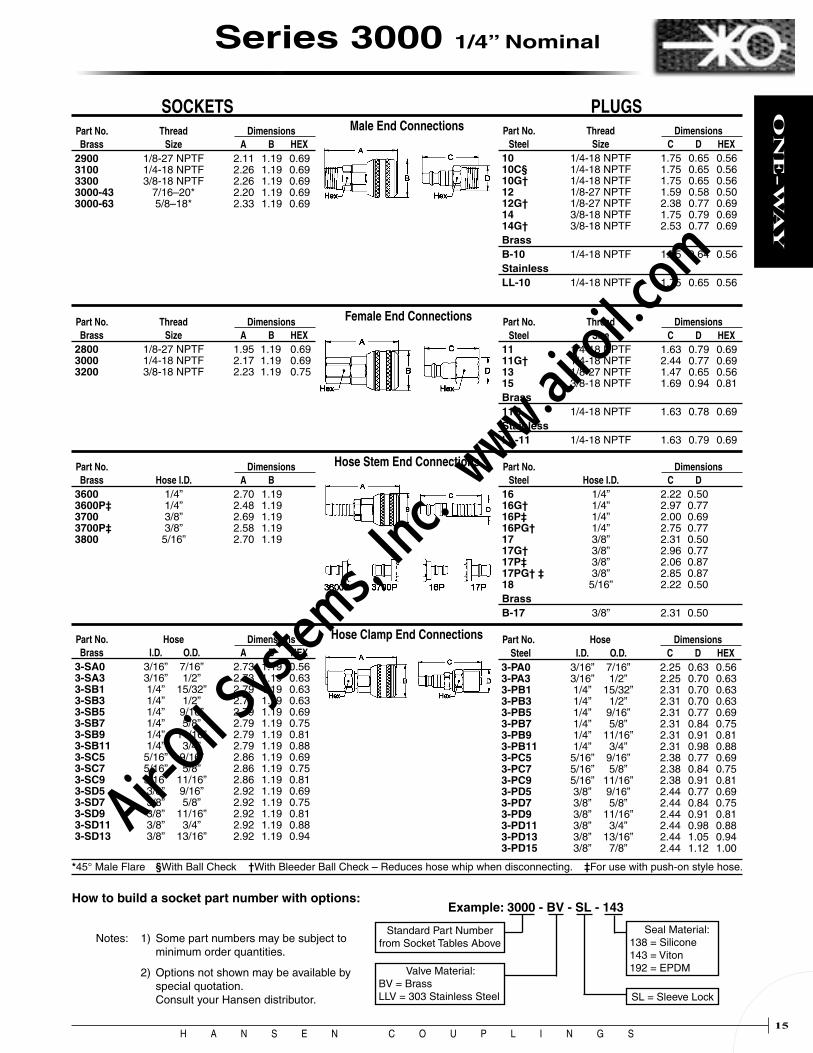
Part No. Thread Dimensions Brass Size A B HEX2900 1/8-27 NPTF 2.11 1.19 0.69 3100 1/4-18 NPTF 2.26 1.19 0.69 3300 3/8-18 NPTF 2.26 1.19 0.69 3000-43 7/16–20* 2.20 1.19 0.69 3000-63 5/8–18* 2.33 1.19 0.69
Part No. Thread Dimensions Steel Size C D HEX 10 1/4-18 NPTF 1.75 0.65 0.56 10C§ 1/4-18 NPTF 1.75 0.65 0.56 10G† 1/4-18 NPTF 1.75 0.65 0.56 12 1/8-27 NPTF 1.59 0.58 0.50 12G† 1/8-27 NPTF 2.38 0.77 0.69 14 3/8-18 NPTF 1.75 0.79 0.69 14G† 3/8-18 NPTF 2.53 0.77 0.69BrassB-10 1/4-18 NPTF 1.75 0.64 0.56StainlessLL-10 1/4-18 NPTF 1.75 0.65 0.56
Part No. Thread Dimensions Brass Size A B HEX2800 1/8-27 NPTF 1.95 1.19 0.69 3000 1/4-18 NPTF 2.17 1.19 0.69 3200 3/8-18 NPTF 2.23 1.19 0.75
Part No. Thread Dimensions Steel Size C D HEX11 1/4-18 NPTF 1.63 0.79 0.69 11G† 1/4-18 NPTF 2.44 0.77 0.69 13 1/8-27 NPTF 1.47 0.65 0.56 15 3/8-18 NPTF 1.69 0.94 0.81Brass11B 1/4-18 NPTF 1.63 0.78 0.69StainlessLL-11 1/4-18 NPTF 1.63 0.79 0.69
Part No. Dimensions Brass Hose I.D. A B 3600 1/4” 2.70 1.19 3600P‡ 1/4” 2.48 1.19 3700 3/8” 2.69 1.19 3700P‡ 3/8” 2.58 1.19 3800 5/16” 2.70 1.19
Part No. Dimensions Steel Hose I.D. C D 16 1/4” 2.22 0.50 16G† 1/4” 2.97 0.77 16P‡ 1/4” 2.00 0.69 16PG† 1/4” 2.75 0.77 17 3/8” 2.31 0.50 17G† 3/8” 2.96 0.77 17P‡ 3/8” 2.06 0.87 17PG† ‡ 3/8” 2.85 0.87 18 5/16” 2.22 0.50 BrassB-17 3/8” 2.31 0.50
Part No. Hose Dimensions Brass I.D. O.D. A B HEX 3-SA0 3/16” 7/16” 2.73 1.19 0.56 3-SA3 3/16” 1/2” 2.73 1.19 0.63 3-SB1 1/4” 15/32” 2.79 1.19 0.63 3-SB3 1/4” 1/2” 2.79 1.19 0.63 3-SB5 1/4” 9/16” 2.79 1.19 0.69 3-SB7 1/4” 5/8” 2.79 1.19 0.75 3-SB9 1/4” 11/16” 2.79 1.19 0.81 3-SB11 1/4” 3/4” 2.79 1.19 0.88 3-SC5 5/16” 9/16” 2.86 1.19 0.69 3-SC7 5/16” 5/8” 2.86 1.19 0.75 3-SC9 5/16” 11/16” 2.86 1.19 0.81 3-SD5 3/8” 9/16” 2.92 1.19 0.69 3-SD7 3/8” 5/8” 2.92 1.19 0.75 3-SD9 3/8” 11/16” 2.92 1.19 0.81 3-SD11 3/8” 3/4” 2.92 1.19 0.88 3-SD13 3/8” 13/16” 2.92 1.19 0.94
Part No. Hose Dimensions Steel I.D. O.D. C D HEX3-PA0 3/16” 7/16” 2.25 0.63 0.56 3-PA3 3/16” 1/2” 2.25 0.70 0.63 3-PB1 1/4” 15/32” 2.31 0.70 0.63 3-PB3 1/4” 1/2” 2.31 0.70 0.63 3-PB5 1/4” 9/16” 2.31 0.77 0.69 3-PB7 1/4” 5/8” 2.31 0.84 0.75 3-PB9 1/4” 11/16” 2.31 0.91 0.81 3-PB11 1/4” 3/4” 2.31 0.98 0.88 3-PC5 5/16” 9/16” 2.38 0.77 0.69 3-PC7 5/16” 5/8” 2.38 0.84 0.75 3-PC9 5/16” 11/16” 2.38 0.91 0.81 3-PD5 3/8” 9/16” 2.44 0.77 0.69 3-PD7 3/8” 5/8” 2.44 0.84 0.75 3-PD9 3/8” 11/16” 2.44 0.91 0.81 3-PD11 3/8” 3/4” 2.44 0.98 0.88 3-PD13 3/8” 13/16” 2.44 1.05 0.94 3-PD15 3/8” 7/8” 2.44 1.12 1.00
How to build a socket part number with options:Example: 3000 - BV - SL - 143
Standard Part Number from Socket Tables Above
Valve Material:BV = Brass LLV = 303 Stainless Steel
Seal Material:138 = Silicone 143 = Viton 192 = EPDM
SL = Sleeve Lock
Notes: 1) Some part numbers may be subject to minimum order quantities.
2) Options not shown may be available by special quotation. Consult your Hansen distributor.
Male End Connections
Female End Connections
Hose Stem End Connections
Hose Clamp End Connections
SOCKETS PLUGS
*45° Male Flare §With Ball Check †With Bleeder Ball Check – Reduces hose whip when disconnecting. ‡For use with push-on style hose.
Series 3000 1/4” Nominal
Air-O
il Sy
stems,
Inc.
www.a
iroil.co
m

H A N S E N C O U P L I N G S16
ON
E-W
AY
Female End Connections
Male End Connections
Hose Clamp End Connections
Hose Stem End Connections
Part No. Thread Dimensions Brass Size A B HEX 4100-A 1/8-27 NPTF 2.20 1.38 0.88 4100 1/4-18 NPTF 2.35 1.38 0.88 4300 3/8-18 NPTF 2.35 1.38 0.88 4500 1/2-14 NPTF 2.54 1.38 0.88
Part No. Thread Dimensions Steel Size C D HEX38 1/8-27 NPTF 1.72 0.72 0.63 40 1/4-18 NPTF 1.88 0.72 0.63 40G† 1/4-18 NPTF 2.65 0.77 0.69 42 3/8-18 NPTF 1.88 0.79 0.69 42G† 3/8-18 NPTF 2.65 0.77 0.69 44 1/2-14 NPTF 2.09 1.01 0.88BrassB-40 1/4-18 NPTF 1.88 0.70 0.63 B-42 3/8-18 NPTF 1.88 0.77 0.69
Part No. Hose Dimensions Brass I.D. O.D. A B HEX4-SB3 1/4” 1/2” 2.92 1.38 0.63 4-SB5 1/4” 9/16” 2.92 1.38 0.69 4-SB7 1/4” 5/8” 2.92 1.38 0.75 4-SB9 1/4” 11/16” 2.92 1.38 0.81 4-SB11 1/4” 3/4” 2.92 1.38 0.88 4-SC7 5/16” 5/8” 2.98 1.38 0.75 4-SD5 3/8” 9/16” 3.04 1.38 0.69 4-SD7 3/8” 5/8” 3.04 1.38 0.75 4-SD9 3/8” 11/16” 3.04 1.38 0.81 4-SD11 3/8” 3/4” 3.04 1.38 0.88 4-SD15 3/8” 7/8” 3.04 1.38 1.00 4-SP13 1/2” 13/16” 3.67 1.38 0.94 4-SP15 1/2” 7/8” 3.67 1.38 1.00 4-SP17 1/2” 15/16” 3.67 1.38 1.06 4-SP19 1/2” 1” 3.67 1.38 1.13
Part No. Hose Dimensions Steel I.D. O.D. C D HEX4-PB1 1/4” 15/32” 2.44 0.70 0.63 4-PB3 1/4” 1/2” 2.44 0.70 0.63 4-PB5 1/4” 9/16” 2.44 0.77 0.69 4-PB7 1/4” 5/8” 2.44 0.84 0.75 4-PB9 1/4” 11/16” 2.44 0.91 0.81 4-PB11 1/4” 3/4” 2.44 0.98 0.88 4-PD5 3/8” 9/16” 2.56 0.77 0.69 4-PD7 3/8” 5/8” 2.56 0.84 0.75 4-PD9 3/8” 11/16” 2.56 0.91 0.81 4-PD11 3/8” 3/4” 2.56 0.98 0.88 4-PD13 3/8” 13/16” 2.56 1.05 0.94 4-PD15 3/8” 7/8” 2.56 1.12 1.00 4-PP13 1/2” 13/16” 3.25 1.05 0.94 4-PP15 1/2” 7/8” 3.25 1.12 1.00 4-PP17 1/2” 15/16” 3.25 1.19 1.06 4-PP19 1/2” 1” 3.25 1.26 1.13
Part No. Thread Dimensions Brass Size A B HEX4000-A 1/8-27 NPTF 2.10 1.38 0.88 4000 1/4-18 NPTF 2.10 1.38 0.88 4200 3/8-18 NPTF 2.35 1.38 0.88 4400 1/2-14 NPTF 2.62 1.38 1.00
Part No. Thread Dimensions Steel Size C D HEX41 1/4-18 NPTF 1.63 0.79 0.69 41G† 1/4-18 NPTF 2.56 0.77 0.69 43 3/8-18 NPTF 1.81 0.94 0.81 43G† 3/8-18 NPTF 2.62 0.84 0.75 45 1/2-14 NPTF 2.06 1.15 1.00BrassB-43 3/8-18 NPTF 1.81 0.91 0.81
Part No. Hose Dimensions Brass I.D. A B 40400 1/4” 2.82 1.38 40500 5/16” 2.82 1.38 40600 3/8” 2.82 1.38 40800 1/2” 2.92 1.38
Part No. Dimensions Steel Hose I.D. C D 404 1/4” 2.34 0.63 406 3/8” 2.34 0.63 408 1/2” 2.34 0.81 BrassB-406 3/8” 2.34 0.63
How to build a socket part number with options:
Example: 4000 - BV - SL - 143
Standard Part Number from Socket Tables Above
Valve Material:BV = Brass LLV = 303 Stainless Steel
Seal Material:138 = Silicone 143 = Viton 192 = EPDM
SL = Sleeve Lock
Notes: 1) Some part numbers may be subject to minimum order quantities.
2) Options not shown may be available by special quotation. Consult your Hansen distributor.
†With Bleeder Ball Check – Reduces hose whip when disconnecting.
SOCKETS PLUGS
Series 4000 3/8” Nominal
All dimensions in inches.
Air-O
il Sy
stems,
Inc.
www.a
iroil.co
m

H A N S E N C O U P L I N G S17
ON
E-W
AY
Male End Connections
Hose Clamp End Connections
Female End Connections
Hose Stem End Connections
Part No. Thread Dimensions Brass Size A B HEX50100 1/4-18 NPTF 2.78 1.50 1.00 5100 3/8-18 NPTF 2.79 1.50 1.00 5300 1/2-14 NPTF 2.98 1.50 1.00 5500 3/4-14 NPTF 2.98 1.50 1.06
Part No. Thread Dimensions Steel Size C D HEX50 1/4-18 NPTF 2.25 0.79 0.69 50G† 1/4-18 NPTF 2.90 0.98 0.88 52 3/8-18 NPTF 2.25 0.87 0.75 52G† 3/8-18 NPTF 2.90 0.98 0.88 54 1/2-14 NPTF 2.44 1.01 0.88 54G† 1/2-14 NPTF 3.09 0.98 0.88 56 3/4-14 NPTF 2.50 1.23 1.06 56G† 3/4-14 NPTF 3.14 1.19 1.06BrassB-52 3/8-18 NPTF 2.25 0.70 0.63 B-54 1/2-14 NPTF 2.44 0.77 0.69
Part No. Hose Dimensions Brass I.D. O.D. A B HEX5-SD5 3/8” 9/16” 3.50 1.50 0.69 5-SD7 3/8” 5/8” 3.50 1.50 0.75 5-SD9 3/8” 11/16” 3.50 1.50 0.81 5-SD11 3/8” 3/4” 3.50 1.50 0.88 5-SD13 3/8” 13/16” 3.50 1.50 0.94 5-SD15 3/8” 7/8” 3.50 1.50 1.00 5-SP13 1/2” 13/16” 4.10 1.50 0.94 5-SP15 1/2” 7/8” 4.10 1.50 1.00 5-SP17 1/2” 15/16” 4.10 1.50 1.06 5-SP19 1/2” 1” 4.10 1.50 1.13 5-SR23 3/4” 11/8” 4.23 1.50 1.25 5-SR25 3/4” 13/16” 4.23 1.50 1.31 5-SR27 3/4” 11/4” 4.23 1.50 1.38
Part No. Hose Dimensions Steel I.D. O.D. C D HEX5-PB1 1/4” 15/32” 2.81 0.70 0.63 5-PB3 1/4” 1/2” 2.81 0.70 0.63 5-PB5 1/4” 9/16” 2.81 0.77 0.69 5-PB7 1/4” 5/8” 2.81 0.84 0.75 5-PD5 3/8” 9/16” 2.94 0.77 0.69 5-PD7 3/8” 5/8” 2.94 0.84 0.75 5-PD9 3/8” 11/16” 2.94 0.91 0.81 5-PD11 3/8” 3/4” 2.94 0.98 0.88 5-PD13 3/8” 13/16” 2.94 1.05 0.94 5-PD15 3/8” 7/8” 2.94 1.12 1.00 5-PP13 1/2” 13/16” 3.62 1.05 0.94 5-PP15 1/2” 7/8” 3.62 1.12 1.00 5-PP17 1/2” 15/16” 3.62 1.19 1.06 5-PP19 1/2” 1” 3.62 1.26 1.13 5-PR23 3/4” 11/8” 3.75 1.40 1.25 5-PR25 3/4” 13/16” 3.75 1.47 1.31 5-PR27 3/4” 11/4” 3.75 1.54 1.38
Part No. Thread Dimensions Brass Size A B HEX5000-A 1/4-18 NPTF 2.72 1.50 1.00 5000 3/8-18 NPTF 2.79 1.50 1.00 5200 1/2-14 NPTF 3.07 1.50 1.00 5400 3/4-14 NPTF 3.10 1.50 1.19
Part No. Thread Dimensions Steel Size C D HEX53-A 1/4-18 NPTF 1.92 0.79 0.69 53 3/8-18 NPTF 2.06 0.94 0.81 53G† 3/8-18 NPTF 2.90 0.98 0.88 55 1/2-14 NPTF 2.34 1.15 1.00 55G† 1/2-14 NPTF 3.17 0.98 0.88 57 3/4-14 NPTF 2.44 1.37 1.19
Part No. Dimensions Brass Hose I.D. A B 50400 1/4” 3.26 1.50 50500 5/16” 3.29 1.50 5700 3/8” 3.33 1.50 5800 1/2” 3.25 1.50 5900 3/4” 4.10 1.50
Part No. Dimensions Steel Hose I.D. C D 585 5/16” 2.66 0.69 585G† 5/16” 3.37 0.98 59 3/8” 2.66 0.69 59G† 3/8” 3.37 0.98 60 1/2” 2.66 0.75 60G† 1/2” 3.37 0.98 61 3/4” 3.50 1.00 61G† 3/4” 4.22 0.98 BrassB-60 1/2” 2.75 0.88
How to build a socket part number with options:
Example: 5000 - BV - SL - 143
Standard Part Number from Socket Tables Above
Valve Material:BV = Brass LLV = 303 Stainless Steel
Seal Material:143 = Viton 192 = EPDM
SL = Sleeve Lock
Notes: 1) Some part numbers may be subject to minimum order quantities.
2) Options not shown may be available by special quotation. Consult your Hansen distributor.
SOCKETS PLUGS
†With Bleeder Ball Check – Reduces hose whip when disconnecting.
Series 5000 1/2” Nominal
Air-O
il Sy
stems,
Inc.
www.a
iroil.co
m

H A N S E N C O U P L I N G S18
ON
E-W
AY
Female End Connections
Male End Connections
Hose Stem End Connections
Part No. Thread Dimensions Brass Size A B HEX6300 1/2-14 NPTF 2.94 1.88 1.31 6500 3/4-14 NPTF 2.94 1.88 1.31 6700 1-111/2 NPTF 3.13 1.88 1.31
Part No. Thread Dimensions Steel Size C D HEX64A 1/2-14 NPTF 2.31 1.15 1.00 64GA† 1/2-14 NPTF 3.26 1.12 1.00 66A 3/4-14 NPTF 2.38 1.23 1.06 66GA† 3/4-14 NPTF 3.26 1.19 1.06 68A 1-111/2 NPTF 2.56 1.52 1.31
BrassB-64A 1/2-14 NPTF 2.31 1.12 1.00 B-66A 3/4-14 NPTF 2.38 1.19 1.06
Part No. Thread Dimensions Brass Size A B HEX6200 1/2-14 NPTF 2.85 1.88 1.31 6400 3/4-14 NPTF 3.00 1.88 1.31 6600 1-111/2 NPTF 3.19 1.88 1.56
Part No. Thread Dimensions Steel Size C D HEX65A 1/2-14 NPTF 2.22 1.15 1.00 65GA† 1/2-14 NPTF 3.35 1.12 1.00 67A 3/4-14 NPTF 2.22 1.37 1.19 67GA† 3/4-14 NPTF 3.38 1.33 1.19 69A 1-111/2 NPTF 2.41 1.80 1.56
Part No. Hose Dimensions Brass I.D. A B 6800 1/2” 3.21 1.88 6900 3/4” 4.06 1.88 7000 1” 4.07 1.88
Part No. Dimensions Steel Hose I.D. C D 70A 1/2” 2.53 0.94 70GA† 1/2” 3.53 1.12 71A 3/4” 3.44 1.06 71GA† 3/4” 4.38 1.12 72A 1” 3.44 1.31 BrassB-71A 3/4” 3.44 1.06
†With Bleeder Ball Check – Reduces hose whip when disconnecting.
Example: 6000 - BV - SL - 143
Standard Part Number from Socket Tables Above
Valve Material:BV = Brass
Seal Material: 143 = Viton
SL = Sleeve Lock
SOCKETS PLUGS
How to build a socket part number with options:
Notes: 1) Some part numbers may be subject to minimum order quantities.
2) Options not shown may be available by special quotation. Consult your Hansen distributor.
Series 6000 3/4” Nominal
All dimensions in inches.
Air-O
il Sy
stems,
Inc.
www.a
iroil.co
m

H A N S E N C O U P L I N G S19
ON
E-W
AYSeries P-30 & P-40
Industrial Interchange
Industrial Interchange Plastic Quick Connect Couplings designed for compressed air. Body sizes are 1/4” and 3/8”.
Thread Dimensions Part No. Size C D HEX P4-30P-25M 1/4-18 NPTF 1.75 0.65 0.56 P7-40P-37M 3/8-18 NPTF 1.88 0.79 0.69
Sockets Plugs
Dimensions Part No. Hose I.D. A B P4-30S-25H 1/4” 2.66 1.25 P7-40S-37H 3/8” 2.82 1.44
Flow CapacitySeries † AcP-30 28P-40 45
† Air flow (scfm) with 5 psi pressure drop and 100 psig inlet pressure
Rated PressureSeries Size PSI BAR
P-30 1/4” 150 10 P-40 3/8” 150 10
* At temperatures up to 125°
Male End ConnectionsHose Stem End Connections
Features
• Plastic socket body and plug
• Light-weight
• Less likely to damage painted or easily dented surfaces than metal couplings
• Easy, automatic, push-to-connect design provides instantaneous connection and disconnection of lines, plus automatic shut-off of socket end of line
• 1/4” socket accepts MIL-C-4109 plugs
Standard Materials• Socket - Acetal Body - Polypropylene Sleeve - Zinc Plated Steel Valve - Buna-N (Nitrile) Seal - Stainless Steel Springs • Plug
- Acetal
- Series P-30 accepts all Series 3000 plugs
- Series P-40 accepts all Series 4000 plugs
Air-O
il Sy
stems,
Inc.
www.a
iroil.co
m

H A N S E N C O U P L I N G S20
ON
E-W
AY
Series AUTO-FLO 23 & 241/4” Nominal
Standard Materials
• Socket - Brass Body - Brass Valve - Zinc Plated Steel Sleeve - Buna-N (Nitrile) Seals - Stainless Steel Springs - Stainless Steel Locking Balls
• Plug - Industrial Interchange (Series 3000) • Zinc Plated Case-Hardened Steel • Brass • Stainless Steel
- ARO 210, Tru-Flate and CEJN/Rectus Interchanges • Zinc Plated Case-Hardened Steel
High flow, automatic Quick-Connect Couplings designed for use with compressed air. See page 9 for One-Way Plug Interchange Chart.
Pressure RatingsSeries PSI BARAuto-Flo 23 150 10Auto-Flo 24 150 10
Flow CapacitiesPlug Interchange † AcIndustrial 32ARO 210 32Tru-Flate 30Auto-Flo 24 45
Auto-Flo 23 Socket
Industrial Interchange Plug
ARO 210 Interchange Plug
Tru-Flate Interchange Plug
Auto-Flo 24 Socket
Auto-Flo 24 Plug
Features
• Auto-Flo 23 is the first automatic universal coupling designed to operate with Industrial, ARO 210 and Tru-Flate Interchange plugs
• Auto-Flo 24 operates with CEJN 320 and Rectus 25 Interchange plugs
• Easy, automatic, push-to-connect design provides instantaneous connection and disconnection of lines, plus automatic shut-off of socket end of line
• Sleeve guard protects against accidental disconnection
† Air flow (scfm) with 5 psi pressure drop and 100 psig inlet pressure
Air-O
il Sy
stems,
Inc.
www.a
iroil.co
m

H A N S E N C O U P L I N G S21
ON
E-W
AY
Dimensions Part No. Hose I.D. A BB23AS-25H 1/4” 2.76 0.94 B23AS-31H 5/16” 2.73 0.94 B23AS-37H 3/8” 2.73 0.94 B23AS-50H 1/2” 2.70 0.94
Thread Dimensions Part No. Size A B HEXB23AS-25F 1/4-18 NPTF 2.02 0.94 0.81 B23AS-25FBS 1/4-19 BSPP 2.02 0.94 0.81 B23AS-37F 3/8-18 NPTF 2.02 0.94 0.81 B23AS-37FBS 3/8-19 BSPP 2.02 0.94 0.81 B23AS-50FBS 3/8-14 BSPP 2.34 0.94 1.06
Thread Dimensions Part No. Size A B HEXB23AS-25M 1/4-18 NPTF 2.23 0.94 0.81 B23AS-25MBST 1/4-19 BSPT 2.23 0.94 0.81 B23AS-37M 3/8-18 NPTF 2.23 0.94 0.81 B23AS-37MBST 3/8-19 BSPT 2.23 0.94 0.81 B23AS-50MBST 1/2-14 BSPT 2.23 0.94 0.88
Part No. Thread Dimensions Steel Size C D HEX INDUSTRIAL INTERCHANGE (Series 3000, page 15)
2607 1/8-27 NPTF 1.42 0.58 0.50 2608 1/4-18 NPTF 1.68 0.65 0.56 2608B 1/4-19 BSPT 1.68 0.65 0.56 20AP-37M 3/8-18 NPTF 1.68 0.79 0.69 ARO 210 INTERCHANGE 21AP-25M 1/4-18 NPTF 1.65 0.65 0.56 21AP-37M 3/8-18 NPTF 1.65 0.79 0.69 Tru-Flate INTERCHANGE
Part No. Thread Dimensions Steel Size C D HEX INDUSTRIAL INTERCHANGE (Series 3000, page 15)
2609 1/4-18 NPTF 1.55 0.79 0.69 2609B 1/4-19 BSPP 1.55 0.79 0.69 20AP-37F 3/8-18 NPTF 1.61 0.94 0.81 ARO 210 INTERCHANGE 21AP-25F 1/4-18 NPTF 1.53 0.79 0.69 21AP-37F 3/8-18 NPTF 1.59 0.94 0.81 Tru-Flate INTERCHANGE
Part No. Dimensions Steel Hose I.D. C D INDUSTRIAL INTERCHANGE (Series 3000, page 15)
3946 1/4” 2.14 0.50 3947 5/16” 2.14 0.50 22238 3/8” 2.14 0.50 ARO 210 INTERCHANGE 21AP-25H 1/4” 2.12 0.50 21AP-37H 3/8” 2.12 0.50 Tru-Flate INTERCHANGE
SOCKETS Auto-Flo 23 PLUGS
Series AUTO-FLO 23 & 241/4” Nominal
Male End Connections
Female End Connections
Hose Stem End Connections
Air-O
il Sy
stems,
Inc.
www.a
iroil.co
m

H A N S E N C O U P L I N G S22
ON
E-W
AY
Part No. Thread Dimensions Steel Size C D HEX24AP-25MG 1/4-18 NPTF 1.64 0.65 0.56 24AP-25MBST 1/4-19 BSPT 1.62 0.65 0.56 24AP-37MBST 3/8-19 BSPT 1.62 0.79 0.69 24AP-50MBST 1/2-14 BSPT 1.88 1.01 0.88
Part No. Thread Dimensions Brass Size A B HEXB24AS-25M 1/4-18 NPTF 2.27 0.94 0.81 B24AS-25MBST 1/4-19 BSPT 2.27 0.94 0.81 B24AS-37MBST 3/8-19 BSPT 2.27 0.94 0.81 B24AS-50MBST 1/2-14 BSPT 2.27 0.94 0.88
Part No. Dimensions Brass Hose I.D. A B B24AS-25H 1/4” 2.80 0.94 B24AS-31H 5/16” 2.77 0.94 B24AS-37H 3/8” 2.77 0.94 B24AS-50H 1/2” 2.74 0.94
Part No. Thread Dimensions Steel Size C D HEX24AP-25FG 1/4-18 NPTF 1.49 0.79 0.69 24AP-25FBS 1/4-19 BSPP 1.46 0.79 0.69 24AP-37FBS 3/8-19 BSPP 1.52 0.94 0.81 24AP-50FBS 1/2-14 BSPP 1.65 1.23 1.06
Part No. Thread Dimensions Brass Size A B HEXB24AS-25F 1/4-18 NPTF 2.06 0.94 0.81 B24AS-25FBS 1/4-19 BSPP 2.06 0.94 0.81 B24AS-37FBS 3/8-19 BSPP 2.06 0.94 0.81 B24AS-50FBS 1/2-14 BSPP 2.38 0.94 1.06
SOCKETS Auto-Flo 24 PLUGS
Part No. Dimensions Steel Hose I.D. C D 24AP-25H 1/4” 2.08 0.50 24AP-31H 5/16” 2.08 0.50 24AP-37H 3/8” 2.08 0.50 24AP-50H 1/2” 2.08 0.63
Male End Connections
Female End Connections
Hose Stem End Connections
Series AUTO-FLO 23 & 241/4” Nominal
Air-O
il Sy
stems,
Inc.
www.a
iroil.co
m

H A N S E N C O U P L I N G S23
ON
E-W
AY
Hose Stem End Connections
The SAFELINE Industrial Interchange pushbutton safety coupling is designed for use with compressed air.Features
• Safe and easy to connect and disconnect. Two-step disconnect procedure shuts off air supply and releases downstream air pressure before plug can be removed from socket. Hose whip is prevented.
• Light weight, compact ergonomic design
• Accepts 1/4” MIL-C-4109 plugs
Operation
• To connect: Push plug into socket
• To disconnect: (1) Push button on side of socket. Air supply is shut off and plug pops out 3/16 inch, but is not released from socket. Downstream air is vented. (2) Push plug into socket to release latch. Pull plug from socket.
Standard Materials
• Socket
- Aluminum and steel construction
- Buna-N (Nitrile) Seals
• Plug: Use Series 3000 Plugs
Thread Dimensions Part No. Thread Size A B HEXGD 10536 41 1/4-18 NPTF 3.18 1.02 0.67 GD 10536 83 3/8-18 NPTF 3.18 1.02 0.75
Flow CapacitySeries † AcGD 10500 20
† Air flow (scfm) with 5 psi pressure drop and 100 psig inlet pressure
Female End Connections
Male End Connections
Rated PressureSeries PSI BarGD 10500 232 16
Series SAFELINE 1/4” Industrial Interchange
Thread Dimensions Part No. Thread Size A B HEXGD 10526 41 1/4-18 NPTF 2.97 1.02 0.67 GD 10526 83 3/8-18 NPTF 3.18 1.02 0.87
Dimensions Part No. Hose I.D. A B GD 10556 67 1/4” 3.56 1.02 GD 10556 01 3/8” 3.56 1.02
Air-O
il Sy
stems,
Inc.
www.a
iroil.co
m
H A N S E N C O U P L I N G S24
ON
E-W
AY
Female End Connections
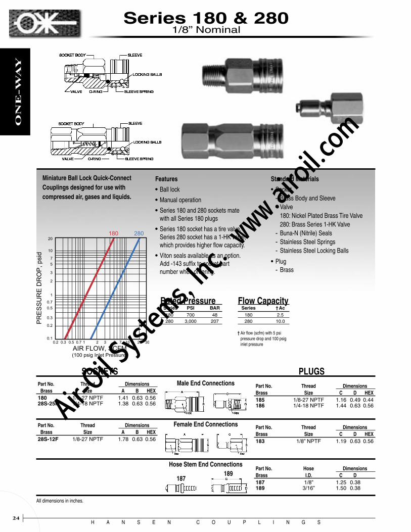
Miniature Ball Lock Quick-Connect Couplings designed for use with compressed air, gases and liquids.
Male End Connections
Flow Capacity Series † Ac 180 2.5 280 10.0
Part No. Thread Dimensions Brass Size A B HEX180 1/8-27 NPTF 1.41 0.63 0.56 28S-25M 1/4-18 NPTF 1.38 0.63 0.56
Part No. Thread Dimensions Brass Size A B HEX28S-12F 1/8-27 NPTF 1.78 0.63 0.56
Part No. Thread Dimensions Brass Size C D HEX185 1/8-27 NPTF 1.16 0.49 0.44 186 1/4-18 NPTF 1.44 0.63 0.56
Part No. Thread Dimensions Brass Size C D HEX183 1/8” NPTF 1.19 0.63 0.56
† Air flow (scfm) with 5 psi pressure drop and 100 psig inlet pressure
SOCKETS PLUGS
Features
• Ball lock
• Manual operation
• Series 180 and 280 sockets mate with all Series 180 plugs
• Series 180 socket has a tire valve. Series 280 socket has a 1-HK valve, which provides higher flow capacity.
• Viton seals available as an option. Add -143 suffix to socket part number when ordering.
Standard Materials
• Socket - Brass Body and Sleeve - Valve 180: Nickel Plated Brass Tire Valve 280: Brass Series 1-HK Valve - Buna-N (Nitrile) Seals - Stainless Steel Springs - Stainless Steel Locking Balls
• Plug - Brass
Rated PressureSeries PSI BAR
180 700 48 280 3,000 207
Series 180 & 280 1/8” Nominal
Hose Stem End Connections
All dimensions in inches.
189187
Part No. Hose DimensionsBrass I.D. C D187 1/8” 1.25 0.38 189 3/16” 1.50 0.38
Air-O
il Sy
stems,
Inc.
www.a
iroil.co
m

H A N S E N C O U P L I N G S25
ON
E-W
AY
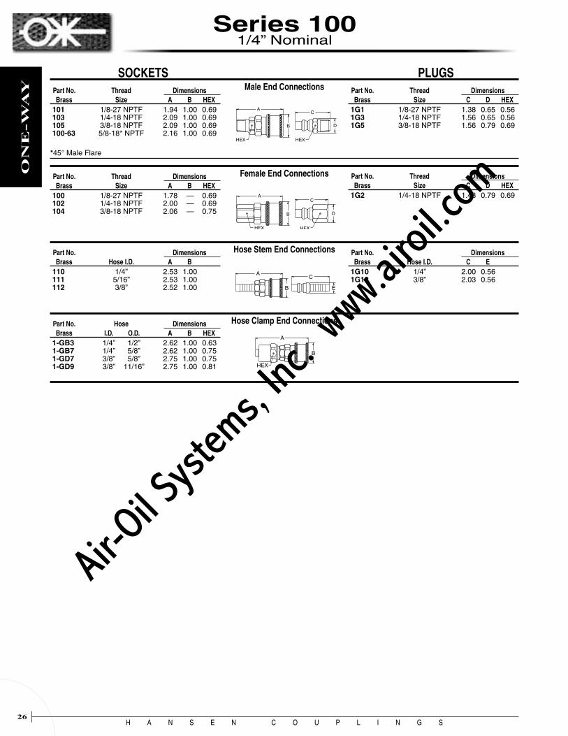
Series 100 1/4” Nominal
Quick-Connect Coupling designed for applications where non- interchange with other couplings is a requirement.
Flow CapacitySeries ‡ Ac100 20
‡ Air flow (scfm) with 5 psi pressure drop and 100 psig inlet pressure
Rated PressureSeries PSI BAR100 350 24
Standard Materials
• Socket - Brass Body - Brass Valve - Brass Sleeve - Buna-N (Nitrile) Seal - Stainless Steel Springs - Stainless Steel Locking Balls• Plug - Brass
Accessories
• Dust caps and dust plugs (See page 68)
Features
• Ball lock • Manual operation • Non-interchangeable design prevents crossing of lines
SOCKET BODY
SOCKET END
VALVE SLEEVE SPRING
LOCKING BALLS
VALVE WASHER
SLEEVE
Air-O
il Sy
stems,
Inc.
www.a
iroil.co
m
H A N S E N C O U P L I N G S26
ON
E-W
AY
Series 100 1/4” Nominal
Female End Connections
Male End Connections
Hose Stem End Connections
Part No. Thread Dimensions Brass Size A B HEX101 1/8-27 NPTF 1.94 1.00 0.69 103 1/4-18 NPTF 2.09 1.00 0.69 105 3/8-18 NPTF 2.09 1.00 0.69 100-63 5/8-18* NPTF 2.16 1.00 0.69
Part No. Thread Dimensions Brass Size C D HEX1G1 1/8-27 NPTF 1.38 0.65 0.56 1G3 1/4-18 NPTF 1.56 0.65 0.56 1G5 3/8-18 NPTF 1.56 0.79 0.69
Part No. Thread Dimensions Brass Size A B HEX100 1/8-27 NPTF 1.78 — 0.69 102 1/4-18 NPTF 2.00 — 0.69 104 3/8-18 NPTF 2.06 — 0.75
Part No. Thread Dimensions Brass Size C D HEX1G2 1/4-18 NPTF 1.43 0.79 0.69
SOCKETS PLUGS
*45° Male Flare
Hose Clamp End Connections Part No. Hose Dimensions Brass I.D. O.D. A B HEX1-GB3 1/4” 1/2” 2.62 1.00 0.63 1-GB7 1/4” 5/8” 2.62 1.00 0.75 1-GD7 3/8” 5/8” 2.75 1.00 0.75 1-GD9 3/8” 11/16” 2.75 1.00 0.81
Part No. Dimensions Brass Hose I.D. A B 110 1/4” 2.53 1.00 111 5/16” 2.53 1.00 112 3/8” 2.52 1.00
Part No. Dimensions Brass Hose I.D. C E 1G10 1/4” 2.00 0.56 1G12 3/8” 2.03 0.56
A
HEX
B
C
HEX
D
A
HEX
B
C
HEX
D
A
B
C
E
A
B
HEX
Air-O
il Sy
stems,
Inc.
www.a
iroil.co
m

H A N S E N C O U P L I N G S27
ON
E-W
AY
Quick-Connect Couplings designed for use in oxyacetylene service. Series 600 is used with oxygen. Series 700 is used with acetylene.
Flow CapacitySeries ‡ Ac600 & 700 20
‡ Air flow (scfm) with 5 psi pressure drop and 100 psig inlet pressure
Rated PressureSeries PSI BAR600 & 700 1,500 103
Series 700 Series 600
Standard Materials
• Socket - Brass Body - Brass Valve - Painted Brass Sleeve Green - Series 600 Red - Series 700 - Buna-N (Nitrile) Seal - Stainless Steel Springs - Stainless Steel Locking Balls• Plug - Brass
Accessories
• Dust caps and dust plugs (See page 68)
Features
• Ball lock • Manual operation • Non-interchangeable designs prevent crossing of lines • Sleeves are color coded to identify each series: - Series 600 sleeves are green for oxygen - Series 700 sleeves are red for acetylene • Socket part numbers with the prefix UL are UL listed for their intended usage • Sockets having part numbers with the UL prefix or SL suffix have the sleeve lock feature to prevent accidental disconnection • Sockets with hose connections cannot be UL listed • Series 600 and 700 couplings can also be used with compressed air and other gases
Series 600 & 700 1/4” Nominal
Air-O
il Sy
stems,
Inc.
www.a
iroil.co
m

H A N S E N C O U P L I N G S28
ON
E-W
AY
Hose Clamp End Connections
Hose Stem End Connections
Female End Connections
Part No. Thread Dimensions Brass Size C D HEX 01A 1/8-27 NPTF 1.41 0.63 0.56 03A 1/4-18 NPTF 1.56 0.63 0.56 04-R 9/16-18† 1.41 0.63 0.56
Part No. - Brass Thread DimensionsStandard Oxygen Serv. Size A B HEX GR-600 UL-600 1/8-27 NPTF 1.78 1.00 0.69 GR-602 UL-602 1/4-18 NPTF 2.00 1.00 0.69 GR-604 UL-604 3/8-18 NPTF 2.06 1.00 0.69 GR-605R UL-605R 9/16-18‡ 2.00 1.00 0.69
Part No. Thread Dimensions Brass Size C D HEX00A 1/8-27 NPTF 1.22 0.63 0.56 02A 1/4-18 NPTF 1.41 0.77 0.69 05-R 9/16-18‡ 1.38 0.77 0.69
Part No. - Brass Hose DimensionsStandard Oxygen Serv. I.D. A B GR-606 GR-606-SL 1/4” 2.53 1.00 GR-606P§ GR-606P-SL§ 1/4” 2.31 1.00 GR-607 GR-607-SL 5/16” 2.53 1.00 GR-608 GR-608-SL 3/8” 2.52 1.00 GR-608P§ — 3/8” 2.41 1.00
Part No. Dimensions Brass Hose I.D. C D 07A 1/4” 2.03 0.56 08A 5/16” 2.03 0.56 09A 3/8” 2.04 0.56
Part No. - Brass Hose Dimensions Standard Oxygen Serv. I.D. O.D. A B HEX GR-6-0A3 — 3/16” 1/2” 2.56 1.00 0.63 GR-6-0B3 GR-6-0B3-SL 1/4” 1/2” 2.62 1.00 0.63 GR-6-0B5 GR-6-0B5-SL 1/4” 9/16” 2.62 1.00 0.69 GR-6-0B7 GR-6-0B7-SL 1/4” 5/8” 2.62 1.00 0.75 GR-6-0C5 — 5/16” 9/16” 2.69 1.00 0.69 GR-6-0C7 — 5/16” 5/8” 2.69 1.00 0.75 GR-6-0C9 — 5/16” 11/16” 2.69 1.00 0.81 GR-6-0D7 — 3/8” 5/8” 2.75 1.00 0.75 GR-6-0D9 — 3/8” 11/16” 2.75 1.00 0.81 GR-6-0D11 — 3/8” 3/4” 2.75 1.00 0.88
Part No. Hose Dimensions Brass I.D. O.D. C D HEX6-B3 1/4” 1/2” 2.13 0.70 0.63 6-B5 1/4” 9/16” 2.13 0.77 0.69 6-B7 1/4” 5/8” 2.13 0.84 0.75 6-B9 1/4” 11/16” 2.13 0.91 0.81 6-D5 3/8” 9/16” 2.25 0.77 0.69 6-D7 3/8” 5/8” 2.25 0.84 0.75 6-D9 3/8” 11/16” 2.25 0.91 0.81 6-D11 3/8” 3/4” 2.25 0.98 0.88
Male End Connections SOCKETS PLUGS
*45° Male Flare †R.H. Thread - 30° Female Flare ‡R.H. Thread - Inverted Flare §For use with push-on style hose.
Part No. - Brass Thread DimensionsStandard Oxygen Serv. Size A B HEXGR-601 UL-601 1/8-27 NPTF 1.94 1.00 0.69 GR-603 UL-603 1/4-18 NPTF 2.09 1.00 0.69 GR-604R UL-604R 9/16-18† 1.97 1.00 0.69 GR-605 UL-605 3/8-18 NPTF 2.09 1.00 0.69
Series 600 1/4” Nominal
Fittings Oxygen Adapters—Brass Pipe-to-Pipe Adapters—Brass Swivel Nut Hose Clamps 9/16”–18 Right-Hand Thread for Oxygen Service
Part No. I.D. Hose O.D. Hose 4RA0 3/16” 7/16” 4RA3 3/16” 1/2” 4RB1 1/4” 15/32” 4RB3 1/4” 1/2” 4RB5 1/4” 9/16” 4RB7 1/4” 5/8” 4RD7 3/8” 5/8” 4RD9 3/8” 11/16” 4RD11 3/8” 3/4”
Part No. Connection 18-MAM 1/8” MPT x 1/4” MPT 19-MBM 1/4” MPT x 1/4” MPT 20-MBM 1/4” MPT x 3/8” MPT
Part No. Connection 9-MBR 1/4” MPT x 9/16”–18 RHT
Series UL-600 and UL-700 Couplings with sleeve lock feature comply with O.S.H.A. requirements, Sec. 1915.35 (f)(5), 1916.35 (f)(5), 1917.35 (f)(5), and 1926.350 (f)(5); and are Underwriters’ Laboratories, Inc. listed for use with oxy-acetylene welding and cutting apparatus, file SA 1296.
Series UL-600 couplings are not to be used with oxygen at pressures exceeding 100 psig in order to comply with UL listings.
Oxygen increases combustibility. Fire and explosion could occur causing severe bodily injury or death. Be sure to select the proper coupling for your application and use it only within the specified service pressure range.
All dimensions in inches.
Air-O
il Sy
stems,
Inc.
www.a
iroil.co
m

H A N S E N C O U P L I N G S29
ON
E-W
AY
Hose Clamp End Connections
Hose Stem End Connections
Female End Connections
Part No. Thread Dimensions Brass Size C D HEX A1 1/8-27 NPTF 1.47 0.63 0.56 A3P 1/4-18 NPTF 1.63 0.63 0.56 A4-L 9/16-18† 1.50 0.63 0.56
Part No. - Brass Thread DimensionsStandard Acetyl. Serv. Size A B HEXRD-700 UL-700 1/8-27 NPTF 1.78 1.00 0.69 RD-702 UL-702 1/4-18 NPTF 2.00 1.00 0.69 RD-704 UL-704 3/8-18 NPTF 2.06 1.00 0.69 RD-705L UL-705L 9/16-18‡ 2.00 1.00 0.69
Part No. Thread Dimensions Brass Size C D HEXA2 1/4-18 NPTF 1.46 0.77 0.69 A5-L 9/16-18‡ 1.38 0.77 0.69
Part No. Dimensions Brass Hose I.D. C D A7 1/4” 2.06 0.56 A8 5/16” 2.06 0.56 A9 3/8” 2.10 0.56
Part No. - Brass Hose Dimensions Standard Acetyl. Serv. I.D. O.D. A B HEX RD-7-0A3 — 3/16” 1/2” 2.56 1.00 0.63 RD-7-0B3 RD-7-0B3-SL 1/4” 1/2” 2.62 1.00 0.63 RD-7-0B5 RD-7-0B5-SL 1/4” 9/16” 2.62 1.00 0.69 RD-7-0B7 — 1/4” 5/8” 2.62 1.00 0.75 RD-7-0D7 — 3/8” 5/8” 2.75 1.00 0.75 RD-7-0D9 — 3/8” 11/16” 2.75 1.00 0.81 RD-7-0D11 — 3/8” 3/4” 2.75 1.00 0.88
Part No. Hose Dimensions Brass I.D. O.D. C D HEX7-B3 1/4” 1/2” 2.19 0.70 0.63 7-B5 1/4” 9/16” 2.19 0.77 0.69 7-B7 1/4” 5/8” 2.19 0.84 0.75 7-B11 1/4” 3/4” 2.19 0.98 0.88
Male End Connections SOCKETS PLUGS
†L.H. Thread - 30° Female Flare ‡L.H. Thread - Inverted Flare §For use with push-on style hose.
Part No. - Brass Thread Dimensions Standard Acetyl. Serv. Size A B HEXRD-701 — 1/8-27 NPTF 1.94 1.00 0.69 RD-703 UL-703 1/4-18 NPTF 2.09 1.00 0.69 RD-704L UL-704L 9/16-18† 1.97 1.00 0.69 RD-705 UL-705 3/8-18 NPTF 2.09 1.00 0.69
Part No. - Brass Hose Dimensions Standard Acetyl. Serv. I.D. A B RD-706 RD-706-SL 1/4” 2.53 1.00 RD-706P§ — 1/4” 2.31 1.00 RD-707 RD-707-SL 5/16” 2.53 1.00 RD-708 RD-708-SL 3/8” 2.52 1.00
Series 700 1/4” Nominal
Acetylene is combustible. Fire and explosion could occur causing severe bodily injury or death. Be sure to select the proper coupling for your application and use it only within the specified service pressure range.
Part No. Connection 18-MAM 1/8” MPT x 1/4”
MPT 19-MBM 1/4”
MPT x 1/4” MPT
20-MBM 1/4” MPT x 3/8”
MPT
Series UL-600 and UL-700 Couplings with sleeve lock feature comply with O.S.H.A. requirements, Sec. 1915.35 (f)(5), 1916.35 (f)(5), 1917.35 (f)(5), and 1926.350 (f)(5); and are Underwriters’ Laboratories, Inc. listed for use with oxyacetylene welding and cutting apparatus, file SA 1296.
Series UL-700 couplings are not to be used with acetylene at pressures exceeding 15 psig in order to comply with UL listings.
Part No. I.D. Hose O.D. Hose 4LA0 3/16”
7/16” 4LA3 3/16”
1/2” 4LB3 1/4”
1/2” 4LB5 1/4”
9/16”
Fittings Pipe-to-Pipe Adapters—Brass Swivel Nut Hose Clamps 9/16”–18 Left-Hand Thread for Acetylene Service
All dimensions in inches.
Air-O
il Sy
stems,
Inc.
www.a
iroil.co
m

H A N S E N C O U P L I N G S30
ON
E-W
AY
Series 2RL & 3RL
Ring-Lock Quick-Connect Couplings have a unique interchange which Hansen designed for use with com-pressed air. Body sizes are 1/4” and 3/8”.
Rated PressureSeries Size PSI BAR 2-RL 1/4” 300 20 3-RL 3/8” 300 20
Flow CapacitySeries ‡ Ac 2-RL 48 3-RL 80
‡ Air flow (scfm) with 5 psi pressure drop and 100 psig inlet pressure
Features
• High flow capacity
- 2RL flow equals that of most 3/8” couplings - 3RL flow equals that of most 1/2” couplings
• Ring lock
• Push to connect
• Will not disconnect when hose is dragged on the ground
• Rotate locking sleeve approximately 20° to disconnect
• Optional seal materials available
Standard Materials
• Socket - Zinc Plated Steel Body - Brass Socket End - Nickel Plated Steel Sleeve - Zinc Plated Steel Valve - Buna-N (Nitrile) Seal - Stainless Steel Spring - Zinc Plated Steel Locking Ring
• Plug - Zinc Plated Case-Hardened Steel
Accessories
• Dust caps and dust plugs (See page 68)
Air-O
il Sy
stems,
Inc.
www.a
iroil.co
m

H A N S E N C O U P L I N G S31
ON
E-W
AYSeries 2RL 1/4” Nominal
Male End Connections
Female End Connections
Hose Stem End Connections
Hose Clamp End Connections
Thread Dimensions Part No. Size A B HEX2-R10 1/8-27 NPTF 2.01 1.06 0.88 2-R15 1/4-18 NPTF 2.16 1.06 0.88 2-R20 3/8-18 NPTF 2.16 1.06 0.88 2-R25 1/2-14 NPTF 2.35 1.06 0.88
Part No. Thread Dimensions Steel Size C D HEX2-L10 1/8-27 NPTF 1.51 0.58 0.50 2-L15 1/4-18 NPTF 1.66 0.65 0.56 2-L15G† 1/4-18 NPTF 2.64 0.77 0.69 2-L20 3/8-18 NPTF 2.04 0.79 0.69 2-L20G† 3/8-18 NPTF 2.64 0.77 0.69 2-L25 1/2-14 NPTF 2.31 1.01 0.88
Thread Dimensions Part No. Size A B HEX2-R11 1/8-27 NPTF 1.91 1.06 0.88 2-R16 1/4-18 NPTF 1.91 1.06 0.88 2-R21 3/8-18 NPTF 2.16 1.06 0.88 2-R26 1/2-14 NPTF 2.43 1.06 1.00
Part No. Thread Dimensions Steel Size C D HEX2-L11 1/8-27 NPTF 1.36 0.65 0.56 2-L16 1/4-18 NPTF 1.54 0.79 0.69 2-L16G† 1/4-18 NPTF 2.55 0.77 0.69 2-L21 3/8-18 NPTF 1.88 0.94 0.81 2-L26 1/2-14 NPTF 2.18 1.15 1.00
Dimensions Part No. Hose I.D. A B 2-R17 1/4” 2.63 1.06 2-R195 5/16” 2.63 1.06 2-R22 3/8” 2.63 1.06 2-R27 1/2” 2.63 1.06
Part No. Dimensions Steel Hose I.D. C D2-L17 1/4” 2.13 0.56 2-L195 5/16” 2.13 0.56 2-L22 3/8” 2.13 0.56 2-L27 1/2” 2.50 0.81
Hose Dimensions Part No. I.D. O.D. A B HEX2-R18B1 1/4” 15/32” 2.73 1.06 0.63 2-R18B3 1/4” 1/2” 2.73 1.06 0.63 2-R18B5 1/4” 9/16” 2.73 1.06 0.69 2-R18B7 1/4” 5/8” 2.73 1.06 0.75 2-R18B9 1/4” 11/16” 2.73 1.06 0.81 2-R18B11 1/4” 3/4” 2.73 1.06 0.88 2-R185C5 5/16” 9/16” 2.79 1.06 0.69 2-R185C7 5/16” 5/8” 2.79 1.06 0.75 2-R185C9 5/16” 11/16” 2.79 1.06 0.81 2-R23D5 3/8” 9/16” 2.85 1.06 0.69 2-R23D7 3/8” 5/8” 2.85 1.06 0.75 2-R23D9 3/8” 11/16” 2.85 1.06 0.81 2-R23D11 3/8” 3/4” 2.85 1.06 0.88 2-R23D13 3/8” 13/16” 2.85 1.06 0.94 2-R23D15 3/8” 7/8” 2.85 1.06 1.00 2-R28P13 1/2” 13/16” 3.48 1.06 0.94 2-R28P15 1/2” 7/8” 3.48 1.06 1.00
How to build a socket part number with options:
Notes: 1) Some part numbers may be subject to minimum order quantities.
2) Options not shown may be available by special quotation. Consult your Hansen distributor.
Part No. Hose Dimensions Steel I.D. O.D. C D HEX2-L18B1 1/4” 15/32” 2.23 0.70 0.63 2-L18B3 1/4” 1/2” 2.23 0.70 0.63 2-L18B5 1/4” 9/16” 2.23 0.77 0.69 2-L18B7 1/4” 5/8” 2.23 0.84 0.75 2-L18B9 1/4” 11/16” 2.23 0.91 0.81 2-L18B11 1/4” 3/4” 2.23 0.98 0.88 2-L185C5 5/16” 9/16” 2.29 0.77 0.69 2-L185C7 5/16” 5/8” 2.29 0.84 0.75 2-L185C9 5/16” 11/16” 2.29 0.91 0.81 2-L23D5 3/8” 9/16” 2.35 0.77 0.69 2-L23D7 3/8” 5/8” 2.35 0.84 0.75 2-L23D9 3/8” 11/16” 2.35 0.91 0.81 2-L23D11 3/8” 3/4” 2.35 0.98 0.88 2-L23D13 3/8” 13/16” 2.35 1.05 0.94 2-L23D15 3/8” 7/8” 2.35 1.12 1.00 2-L28P13 1/2” 13/16” 3.41 1.05 0.94 2-L28P15 1/2” 7/8” 3.41 1.12 1.00
SOCKETS PLUGS
Example: 2-R16 - 143
Standard Part Number from Socket Tables Above
Seal Material:138 = Silicone 143 = Viton 192 = EPDM
†With Bleeder Ball Check – Reduces hose whip when disconnecting.
All dimensions in inches.
Air-O
il Sy
stems,
Inc.
www.a
iroil.co
m

H A N S E N C O U P L I N G S32
ON
E-W
AY
Series 3RL 3/8” Nominal
Male End Connections
Female End Connections
Hose Stem End Connections
Hose Clamp End Connections
Thread Dimensions Part No. Size A B HEX3-R15 1/4-18 NPTF 2.34 1.31 1.00 3-R20 3/8-18 NPTF 2.35 1.31 1.00 3-R25 1/2-14 NPTF 2.54 1.31 1.00 3-R30 3/4-14 NPTF 2.54 1.31 1.06
Part No. Thread Dimensions Steel Size C D HEX3-L10 1/8-27 NPTF 1.54 0.72 0.63 3-L15 1/4-18 NPTF 1.70 0.72 0.63 3-L15G† 1/4-18 NPTF 2.64 0.98 0.88 3-L20 3/8-18 NPTF 1.76 0.79 0.69 3-L20G† 3/8-18 NPTF 2.64 0.98 0.88 3-L25 1/2-14 NPTF 2.31 1.01 0.88 3-L25G† 1/2-14 NPTF 2.83 0.98 0.88 3-L30 3/4-14 NPTF 2.38 1.23 1.06 3-L30G† 3/4-14 NPTF 2.88 1.19 1.06
Thread Dimensions Part No. Size A B HEX3-R16 1/4-18 NPTF 2.29 1.31 1.00 3-R21 3/8-18 NPTF 2.35 1.31 1.00 3-R26 1/2-14 NPTF 2.63 1.31 1.00 3-R31A 3/4-14 NPTF 2.66 1.31 1.19
Part No. Thread Dimensions Steel Size C D HEX3-L16 1/4-18 NPTF 1.48 0.79 0.69 3-L16G† 1/4-18 NPTF 2.39 0.98 0.88 3-L21 3/8-18 NPTF 1.63 0.94 0.81 3-L21G† 3/8-18 NPTF 2.64 0.98 0.88 3-L26 1/2-14 NPTF 2.25 1.15 1.00 3-L26G† 1/2-14 NPTF 2.91 0.98 0.88 3-L31 3/4-14 NPTF 2.25 1.37 1.19
Dimensions Part No. Hose I.D. A B 3-R17 1/4” 2.82 1.31 3-R195 5/16” 2.85 1.31 3-R22 3/8” 2.89 1.31 3-R27 1/2” 2.81 1.31 3-R32 3/4” 3.66 1.31
Part No. Dimensions Steel Hose I.D. C D3-L17 1/4” 2.16 0.63 3-L195 5/16” 2.16 0.63 3-L195G† 5/16” 3.11 0.98 3-L22 3/8” 2.16 0.75 3-L22G† 3/8” 3.11 0.98 3-L27 1/2” 2.16 0.81 3-L27G† 1/2” 3.11 0.98 3-L32 3/4” 3.13 1.00 3-L32G† 3/4” 3.96 0.98
Hose Dimensions Part No. I.D. O.D. A B HEX3-R23D5 3/8” 9/16” 3.06 1.31 0.69 3-R23D7 3/8” 5/8” 3.06 1.31 0.75 3-R23D9 3/8” 11/16” 3.06 1.31 0.81 3-R23D11 3/8” 3/4” 3.06 1.31 0.88 3-R23D13 3/8” 13/16” 3.06 1.31 0.94 3-R23D15 3/8” 7/8” 3.06 1.31 1.00 3-R28P13 1/2” 13/16” 3.66 1.31 0.94 3-R28P15 1/2” 7/8” 3.66 1.31 1.00 3-R28P17 1/2” 15/16” 3.66 1.31 1.06 3-R28P19 1/2” 1” 3.66 1.31 1.13 3-R33R23 3/4” 11/8” 3.79 1.31 1.25 3-R33R25 3/4” 13/16” 3.79 1.31 1.31 3-R33R27 3/4” 11/4” 3.79 1.31 1.38
Part No. Hose Dimensions Steel I.D. O.D. C D HEX3-L23D5 3/8” 9/16” 2.45 0.77 0.69 3-L23D7 3/8” 5/8” 2.45 0.84 0.75 3-L23D9 3/8” 11/16” 2.45 0.91 0.81 3-L23D11 3/8” 3/4” 2.45 0.98 0.88 3-L23D13 3/8” 13/16” 2.45 1.05 0.94 3-L23D15 3/8” 7/8” 2.45 1.12 1.00 3-L28P13 1/2” 13/16” 3.14 1.05 0.94 3-L28P15 1/2” 7/8” 3.14 1.12 1.00 3-L28P17 1/2” 15/16” 3.14 1.19 1.06 3-L28P19 1/2” 1” 3.14 1.26 1.13 3-L33R23 3/4” 11/8” 3.56 1.40 1.25 3-L33R25 3/4” 13/16” 3.56 1.47 1.31 3-L33R27 3/4” 11/4” 3.56 1.54 1.38
SOCKETS PLUGS
How to build a socket part number with options:
Notes: 1) Some part numbers may be subject to minimum order quantities.
2) Options not shown may be available by special quotation. Consult your Hansen distributor.
Example: 3-R21 - 143
Standard Part Number from Socket Tables Above
Seal Material: 143 = Viton
†With Bleeder Ball Check – Reduces hose whip when disconnecting.
All dimensions in inches.
Air-O
il Sy
stems,
Inc.
www.a
iroil.co
m
H A N S E N C O U P L I N G S33
TW
O-W
AY
3333
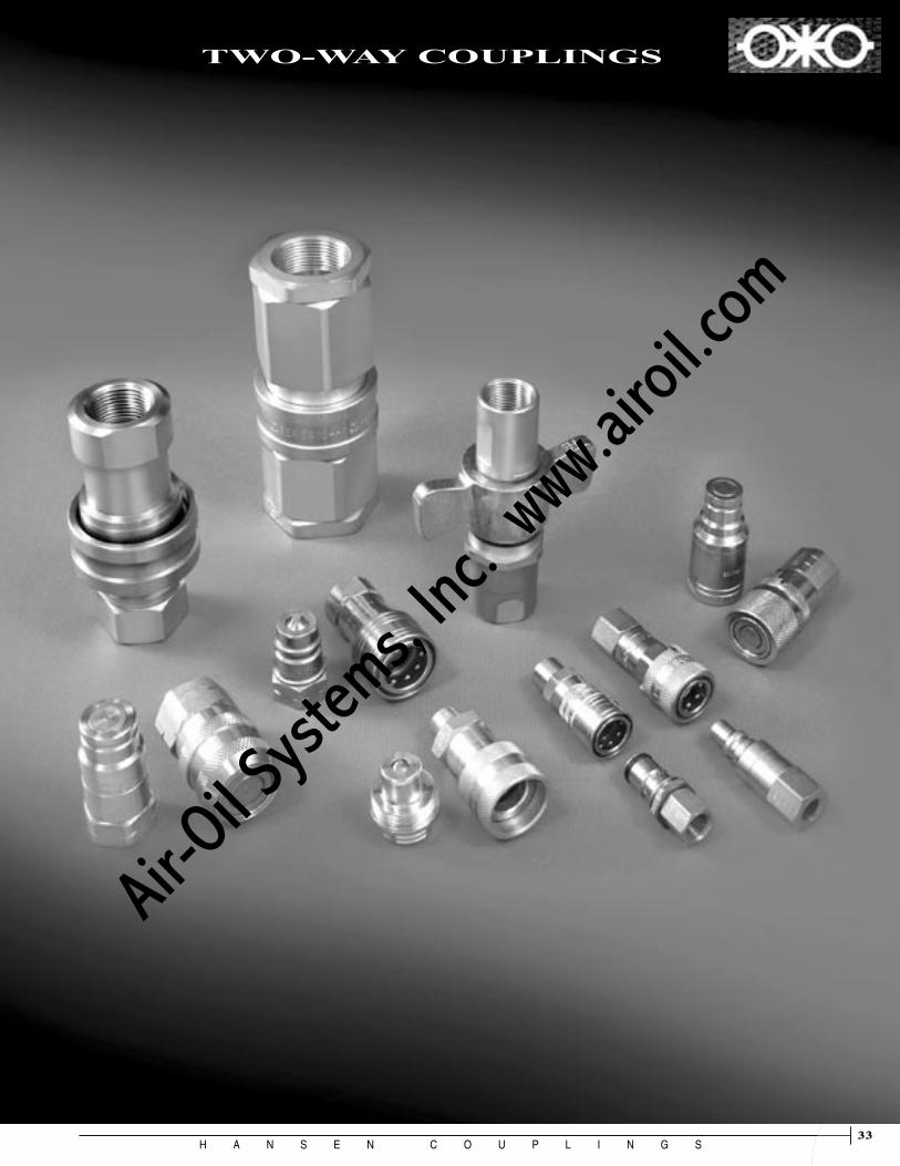
TWO-WAY COUPLINGS
Air-O
il Sy
stems,
Inc.
www.a
iroil.co
m
H A N S E N C O U P L I N G S34
TW
O-W
AY
MA
NU
AL
CO
NN
EC
T
PU
SH
-TO
- C
ON
NE
CT
MIN
IMU
M S
PIL
L/IN
CL
US
ION
1/8
INC
H
1/4
INC
H
3/8
INC
H
1/2
INC
H
3/4
INC
H
1 IN
CH
1¼ IN
CH
1¼ IN
CH
2¼ IN
CH
BR
AS
S
ST
EE
L (
Zin
c/C
hro
mat
e F
inis
h)
STA
INL
ES
S S
TE
EL
(30
3)
STA
INL
ES
S S
TE
EL
(31
6)
PL
AS
TIC
(P
oly
pro
pyl
ene)
BA
LL
LO
CK
TH
RE
AD
ED
SL
EE
VE
PL
AS
TIC
FIN
GE
RS
SL
EE
VE
LO
CK
SE
AL
MA
TE
RIA
LS
(V
ario
us)
DU
ST
CA
P/P
LU
G
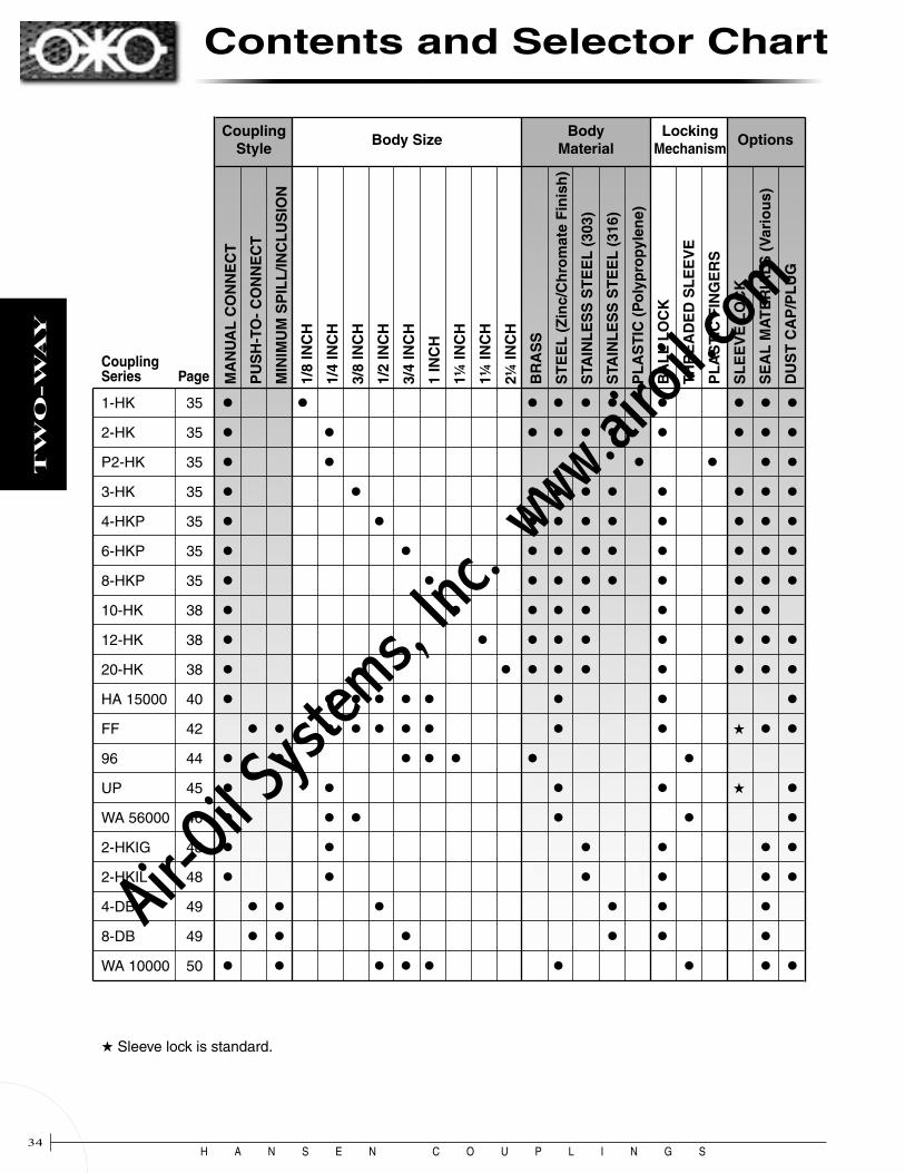
Coupling Series Page
1-HK 35
2-HK 35
P2-HK 35
3-HK 35
4-HKP 35
6-HKP 35
8-HKP 35
10-HK 38
12-HK 38
20-HK 38
HA 15000 40
FF 42 ★
96 44
UP 45 ★
WA 56000 46
2-HKIG 48
2-HKIL 48
4-DB 49
8-DB 49
WA 10000 50
★ Sleeve lock is standard.
Coupling Style
Body SizeBody
MaterialLocking
MechanismOptions
Contents and Selector Chart
Air-O
il Sy
stems,
Inc.
www.a
iroil.co
m

H A N S E N C O U P L I N G S35
TW
O-W
AY
Series HK Couplings are designed for general purpose hydraulic service. Some are suitable for use with various liquids, chemicals, steam, gases and vacuum. Series HK couplings conform to the dimensional requirements of ISO 7241-1 Series B. Body sizes range from 1/8" to 2½".
Features
• Brass, steel and stainless steel construction available in all sizes; polypropylene available in 1/4" body size • End connections are female NPTF, BSPP and SAE o-ring boss • UL listed couplings for use on LP gas fueled lift trucks and tractors available in 1/8", 1/4" and 3/8" body sizes • Heavy duty steel couplings for use in high impulse service available in most sizes • Steam coupling available in 3/8" body size
Standard Materials
• Brass, zinc-plated steel, stainless steel and polypropylene (1/4" only) construction • Stainless steel springs, balls and retaining rings • Buna-N (Nitrile) seals • Teflon back-up rings in 1-HK through 8-HKP steel and stainless steel sockets
Options
• Non-valved socket and plug • Valve actuator in socket or plug • Bleeder-style plug • Sleeve lock • Seals: Teflon, Neoprene,Viton, Buna-N, EPDM and Kalrez (See Elastomer Selection Guide, page 71)
Accessories
• Dust caps and dust plugs (See page 68) • Release clamp with chain
* Polypropylene Construction
Rated Pressure and Flow Capacity Brass Steel Stainless SteelSeries Body Size PSI BAR PSI BAR PSI BAR1-HK 1/8" 3,000 207 4,000 275 5,000 344
2-HK 1/4" 2,700 186 5,000 345 3,700 255
*P2-HK 1/4" 50 4 (+35°F to 150°F)
3-HK 3/8" 2,200 152 3,700 255 3,700 255
4-HKP 1/2" 2,250 155 5,000 345 4,250 293
6-HKP 3/4" 2,000 138 4,000 275 3,500 242
8-HKP 1" 1,500 103 4,000 275 2,500 173
10-HK 1¼" 1,200 83 1,700 118 1,700 118
12-HK 1½" 1,500 104 2,200 152 2,200 152
20-HK 2¾" 700 49 1,500 104 1,500 104
Series 10-HK, 12-HK & 20-HKSeries 1-HK to 8-HKP
Series HK ISO 7241-1 Series B
Air-O
il Sy
stems,
Inc.
www.a
iroil.co
m

H A N S E N C O U P L I N G S36
TW
O-W
AY
Body Size Brass Steel Stainless Steel Thread Size (female) Dimensions (inches) (inch) Standard UL Listed Standard High Impulse 303 316 NPTF BSPP SAE C D E HEX 1/8 B1-K11 UL1-K11 1-K11 — LL1-K11 ML1-K11 1/8-27 — — 1.26 0.65 0.44 0.56 1/8 — — 1-K4 — LL1-K4 — — — 7/16-20 1.41 0.79 0.59 0.69 1/4 B2-K16 UL2-K16 2-K16 2-K16C LL2-K16 ML2-K16 1/4-18 — — 1.52 0.87 0.56 0.75 1/4 B2-K16BS — 2-K16BS — LL2-K16BS ML2-K16BS — 1/4-19 — 1.52 0.87 0.56 0.75 1/4 — — 2-K6 2-K6C LL2-K6 — — — 9/16-18 1.66 1.01 0.70 0.88 3/8 B3-K21 UL3-K21 3-K21 3-K21C LL3-K21 ML3-K21 3/8-18 — 1.76 1.01 0.61 0.88 3/8 B3-K21BS — 3-K21BS — LL3-K21BS ML3-K21BS — 3/8-19 — 1.76 1.01 0.61 0.88 3/8 — — 3-K8 3-K8C LL3-K8 — — — 3/4-16 1.94 1.15 0.79 1.00 1/2 B4-KP26 — 4-KP26 4-KP26 LL4-KP26 ML4-KP26 1/2-14 — — 2.03 1.30 0.76 1.13 1/2 B4-KP26BS — 4-KP26BS 4-KP26BS LL4-KP26BS ML4-KP26BS — 1/2-14 — 2.03 1.30 0.76 1.13 1/2 — — 4-KP10 4-KP10 LL4-KP10 — — — 7/8-14 2.11 1.37 0.84 1.19 3/4 B6-KP31 — 6-KP31 6-KP31 LL6-KP31 ML6-KP31 3/4-14 — — 2.36 1.52 0.71 1.31 3/4 B6-KP31BS — 6-KP31BS 6-KP31BS LL6-KP31BS ML6-KP31BS — 3/4-14 — 2.36 1.52 0.71 1.31 3/4 — — 6-KP12 6-KP12 LL6-KP12 — — — 11/16-12 2.54 1.59 0.89 1.38 1 B8-KP36 — 8-KP36 8-KP36 LL8-KP36 ML8-KP36 1-111/2 — — 2.85 1.88 0.97 1.63 1 B8-KP36BS — 8-KP36BS 8-KP36BS LL8-KP36BS ML8-KP36BS — 1-11 — 2.85 1.88 0.97 1.63 1 — — 8-KP16 8-KP16 LL8-KP16 — — — 15/16-12 2.85 2.17 0.97 1.88
C = Overall Length D = Maximum Diameter E = Exposed Length when Connected
PLUGS
SOCKETS Body Dimensions (inches) Size Brass Steel Stainless Steel Thread Size (female) Across (inch) Standard UL Listed Standard High Impulse 303 316 NPTF BSPP SAE A B Flats 1/8 B1-H11 UL1-H11 1-H11 — LL1-H11 ML1-H11 1/8-27 — — 1.91 0.98 0.56 1/8 — — 1-H4 — LL1-H4 — — — 7/16-20 2.06 0.98 0.69 1/4 B2-H16 UL2-H16 2-H16 2-H16C LL2-H16 ML2-H16 1/4-18 — — 2.26 1.17 0.75 1/4 B2-H16BS — 2-H16BS — LL2-H16BS ML2-H16BS — 1/4-19 — 2.26 1.17 0.75 1/4 — — 2-H6 2-H6C LL2-H6 — — — 9/16-18 2.40 1.17 0.88 3/8 B3-H21 UL3-H21 3-H21 3-H21C LL3-H21 ML3-H21 3/8-18 — 2.56 1.42 0.88 3/8 B3-H21BS — 3-H21BS — LL3-H21BS ML3-H21BS — 3/8-19 — 2.56 1.42 0.88 3/8 — — 3-H8 3-H8C LL3-H8 — — — 3/4-16 2.74 1.42 1.00 1/2 B4-HP26 — 4-HP26 4-HP26 LL4-HP26 ML4-HP26 1/2-14 — — 2.96 1.86 1.13 1/2 B4-HP26BS — 4-HP26BS 4-HP26BS LL4-HP26BS ML4-HP26BS — 1/2-14 — 2.96 1.86 1.13 1/2 — — 4-HP10 4-HP10 LL4-HP10 — — — 7/8-14 3.05 1.86 1.25 3/4 B6-HP31 — 6-HP31 6-HP31 LL6-HP31 ML6-HP31 3/4-14 — — 3.48 2.22 1.31 3/4 B6-HP31BS — 6-HP31BS 6-HP31BS LL6-HP31BS ML6-HP31BS — 3/4-14 — 3.48 2.22 1.31 3/4 — — 6-HP12 6-HP12 LL6-HP12 — — — 11/16-12 3.67 2.22 1.38 1 B8-HP36 — 8-HP36 8-HP36 LL8-HP36 ML8-HP36 1-111/2 — — 4.13 2.61 1.75 1 B8-HP36BS — 8-HP36BS 8-HP36BS LL8-HP36BS ML8-HP36BS — 1-11 — 4.13 2.61 1.75 1 — — 8-HP16 8-HP16 LL8-HP16 — — — 15/16-12 4.13 2.61 1.88
A = Overall Length B = Maximum Diameter
Series 1-HK to 8-HK ISO 7241-1 Series B
All dimensions in inches.
Air-O
il Sy
stems,
Inc.
www.a
iroil.co
m

H A N S E N C O U P L I N G S37
TW
O-W
AY
Series P2-HK Plastic Coupling The Series P2-HK coupling is intended for use with air, water and various chemicals at low pressure. It is designed for use where an economical, light weight, corrorion resistant coupling is desired. All components, except springs and seals, are molded from natural polypropylene with a UV inhibitor. Valve springs are 316 stainless steel. Viton seals are standard. EPDM (192) seals are optional.
Thread Size Dimensions Part No. NPTF C D E HEX PP2-K25F 1/4-18 1.65 1.01 0.67 0.88
Thread Size Dimensions Part No. NPTF A B HEX PP2-H25F 1/4-18 2.38 1.45 0.88
Socket Plug
Series 3-HK Steam Coupling The Hansen Steam Coupling has a large diameter flange on the sleeve to aid gripping while the user wears heavy gloves. EPDM (192) seals are standard, and can be used with steam at temperatures up to 350°F. Options are BSPP threads, sleeve lock, EPDM (236) seals, for use with steam at temperatures above 350°F, and Viton (143) seals.
Dimensions Thread Size Across Part No. NPTF A B Flats B3-H21Y 3/8-18 2.56 1.75 0.88
Socket Plug Thread Size Dimensions Part No. NPTF C D E HEX B3-K21-192 3/8-18 1.76 1.01 0.61 0.88
Release Clamp with Chain When fluid lines may be subjected to a damaging pull, couplings can be mounted to disconnect automatically, sealing both ends of a line against fluid loss. The socket sleeve can be anchored to a stationary bracket, either directly or with a chain. Excessive pull on the plug end of the line moves the socket body forward relative to the sleeve, and the plug is released without damage to the line. Release Clamp Assembly Kits are available for Series 1-HK through 8-HKP sockets.
Bleeder-Style Plugs Bleeder-style plugs can be used on air lines to prevent hose whip when disconnecting a line by reducing the exhaust velocity of air. Bleeder-style plugs can be used on hydraulic lines to prevent static pressure from building up in disconnected lines. Valves of these plugs are manufactured such that a small leak path exists when the plug is disconnected. Bleeder-style plugs are available in Series 1-HK through 6-HKP.
Series Kit Part No. 1-HK 1-HRC-K 2-HK 2-HRC-K 3-HK 3-HRC-K 4-HKP 4-HRC-K 6-HKP 6-HRC-K 8-HKP 8-HRC-K
Series Plug Part No. 1-HK B1-K11-VB 2-HK B2-K16-VB 2-HK 2-K16C-VB 3-HK B3-K21-VB 3-HK 3-K21-VB 3-HK 3-K21C-VB 4-HKP 4-KP26-VB 6-HKP B6-KP31-VB 6-HKP 6-KP31-VB
Series 1-HK to 8-HK ISO 7241-1 Series B
Air-O
il Sy
stems,
Inc.
www.a
iroil.co
m

H A N S E N C O U P L I N G S38
TW
O-W
AY
SOCKETSBody Size Steel 303 Stainless Thread Size (female) Dimensions (inches)
(inch) Brass Standard High Impulse Steel NPTF BSPP A B HEX 11/4 B10-H41 10-H41 — LL10-H41 11/4-111/2 — 4.51 2.73 2.38 11/4 — 10-H41BS — LL10-H41BS — 11/4-11 4.51 2.73 2.38 11/2 B12-H41 12-H41 12-H41C LL12-H41 11/4-111/2 — 4.82 3.23 2.38 11/2 B12-H41BS 12-H41BS — LL12-H41BS — 11/4-11 4.82 3.23 2.38 11/2 B12-H46 12-H46 12-H46C LL12-H46 11/2-111/2 — 4.82 3.23 2.38 11/2 B12-H46BS 12-H46BS — LL12-H46BS — 11/2-11 4.82 3.23 2.38 21/2 B20-H51 20-H51 20-H51C LL20-H51 2-111/2 — 5.55 4.11 3.75 21/2 B20-H51BS 20-H51BS — LL20-H51BS — 2-11 5.55 4.11 3.75 21/2 B20-H56 20-H56 20-H56C LL20-H56 21/2-8 — 6.14 4.11 3.75 21/2 B20-H56BS 20-H56BS — LL20-H56BS — 21/2-11 6.14 4.11 3.75 21/2 B20-H61 20-H61 20-H61C LL20-H61 3-8 — 7.00 4.11 4.00 21/2 B20-H61BS 20-H61BS — LL20-H61BS — 3-11 7.00 4.11 4.00
A = Overall Length B = Maximum Diameter
PLUGSBody Size Steel 303 Stainless Thread Size (female) Dimensions (inches)
(inch) Brass Standard High Impulse Steel NPTF BSPP C D E HEX 11/4 B10-K41 10-K41 — LL10-K41 11/4-111/2 — 4.25 2.73 2.33 2.38 11/4 — 10-K41BS — LL10-K41BS — 11/4-11 4.25 2.73 2.33 2.38 11/2 B12-K41 12-K41 12-K41C LL12-K41 11/4-111/2 — 4.76 3.02 2.67 2.38 11/2 B12-K41BS 12-K41BS — LL12-K41BS — 11/4-11 4.76 3.02 2.67 2.38 11/2 B12-K46 12-K46 12-K46C LL12-K46 11/2-111/2 — 4.76 3.02 2.67 2.38 11/2 B12-K46BS 12-K46BS — LL12-K46BS — 11/2-11 4.76 3.02 2.67 2.38 21/2 B20-K51 20-K51 20-K51C LL20-K51 2-111/2 — 5.49 4.31 2.97 3.75 21/2 B20-K51BS 20-K51BS — LL20-K51BS — 2-11 5.49 4.31 2.97 3.75 21/2 B20-K56 20-K56 20-K56C LL20-K56 21/2-8 — 6.08 4.31 3.56 3.75 21/2 B20-K56BS 20-K56BS — LL20-K56BS — 21/2-11 6.08 4.31 3.56 3.75 21/2 B20-K61 20-K61 20-K61C LL20-K61 3-8 — 6.94 4.31 4.42 4.00 21/2 B20-K61BS 20-K61BS — LL20-K61BS — 3-11 6.94 4.31 4.42 4.00
C = Overall Length D = Maximum Diameter E = Exposed Length when Connected
**ISO 7241-1 Series B does not include 1-1/4 inch body size couplings; therefore, Hansen Series 10-HK is not covered by this standard
Series 10-HK/12-HK/20-HK ISO 7241-1 Series B
All dimensions in inches.
Air-O
il Sy
stems,
Inc.
www.a
iroil.co
m

H A N S E N C O U P L I N G S39
TW
O-W
AY
How to build a socket or plug part number with options:
Notes: 1) The NV option should be specified for a socket and a plug when a non-valved coupling is desired. Non-valved Series 1-HK through 8-HKP plugs do not contain seals. Do not specify a seal material.
2) The VAA option should be specified for a socket or a plug when a one-way coupling is desired.
3) The VB option can be ordered for Series 1-HK through 6-HKP plugs to prevent pressure build-up in disconnected hydraulic lines or to reduce hose whip when disconnecting pneumatic lines.
4) The Sleeve Lock device prevents accidental disconnection. Not available on sockets with prefix UL.
5) Series HK couplings are designed for use with elastomer seals. Teflon is not an elastomer. It is rigid and not resilient. Couplings with Teflon seals may leak and/or be difficult to connect. Force to connect may be reduced by heating connected couplings in hot water; then, cooling before disconnecting. Teflon seals are available for Series 1-HK through 8-HKP, except Series P2-HK.
6) The 146 seal option may be specified for fuels and hydraulic fluids that are known to cause standard Buna-N seals to swell excessively.
7) Couplings with Kalrez seals are available by special quotation.
8) The 236 seal option should be ordered for use with steam at or above 350°F. The 192 seal option should be ordered for hot water above 180°F and steam below 350°F.
9) Some part numbers may be subject to minimum order quantities.
10) Some options may be available only by special quotation. Consult your Hansen distributor.
Example: 4-HP26 - VAA - SL - 143
Standard Part Number from Part Number Tables
NV = No Valve1 VAA = Valve Actuator Assembly2
VB = Bleeder Valve (Plugs Only)3
Seal Material:115 = Teflon5 118 = Neoprene 143 = Viton 146 = Buna-N6
192 = EPDM 235 = Kalrez7
236 = EPDM (350°F+ Steam)8SL = Sleeve Lock (Sockets Only)4
Series HK Special Ordering Instructions
Air-O
il Sy
stems,
Inc.
www.a
iroil.co
m

H A N S E N C O U P L I N G S40
TW
O-W
AY The Series HA 15000 is a general
purpose hydraulic and fluid transfer coupling that conforms to the dimensional requirements of ISO 7241-1 Series A. Body sizes are 1/4", 3/8", 1/2", 3/4" and 1".
Rated PressureBody Size PSI BAR
1/4" 4,568 315 3/8" 4,568 315 1/2" 3,625 250 3/4" 3,625 250 1" 2,900 200
Features
• Ball lock
• Manual connect, disconnect
• Poppet valving
• Slim profile
• Zinc plated steel construction
• NPTF and BSPP end connections
• Available push-to-connect socket designed for bulkhead mounting (1/2" body size only)
Standard Materials
• Zinc-plated steel construction
• Stainless steel springs, balls and retaining rings
• Buna-N (Nitrile) seals
Accessories
• Dust caps and dust plugs (See page 69)
Series HA 15000 ISO 7241-1 Series A
Air-O
il Sy
stems,
Inc.
www.a
iroil.co
m

H A N S E N C O U P L I N G S41
TW
O-W
AY
SOCKETS Body Part Thread Size Dimensions (inches) Size Number (female) Across (inch) (Steel) NPTF BSPP A B Flats
1/4 HA 15211 00 1/4-18 — 1.89 0.98 0.75
1/4 HA 15011 00 — 1/4-19 1.89 0.98 0.75
3/8 HA 15221 00 3/8-18 — 2.21 1.18 0.91
3/8 HA 15021 00 — 3/8-19 2.21 1.18 0.91
1/2 HA 15231 00 1/2-14 — 2.64 1.49 1.06
1/2 HA 15031 00 — 1/2-14 2.64 1.49 1.06
1/2 HA 15236 00* 1/2-14 — 2.64 1.49 1.06
1/2 HA 15036 00* — 1/2-14 2.64 1.49 1.06
3/4 HA 15241 00 3/4-14 — 3.25 1.88 1.38
3/4 HA 15041 00 — 3/4-14 3.25 1.88 1.38
1 HA 15251 00 1-111/2 — 3.86 2.08 1.62
1 HA 15051 00 — 1-11 3.86 2.08 1.62* Push-to-Connect Socket A = Overall Length B = Maximum Diameter
Push-to-Connect Socket - Part Nos. HA 15036 00 & HA 15236 00
This system allows automatic connection and disconnection simply by pushing the plug into or pulling it out of the socket body. Pulling on the hose moves the socket body forward rela-tive to the bulkhead mounted double-acting sleeve, and the plug is released without damage to the hose. Sleeve dimensions for bulkhead mounting are shown at left.
Series HA 15000 ISO 7241-1 Series A
PLUGS Body Part Thread Size Size Number (female) Dimensions (inches) (inch) (Steel) NPTF BSPP C D E Hex 1/4 HA 15212 00 1/4-18 — 1.41 0.86 0.80 0.75
1/4 HA 15012 00 — 1/4-19 1.41 0.86 0.80 0.75
3/8 HA 15222 00 3/8-18 — 1.63 1.04 0.79 0.91
3/8 HA 15022 00 — 3/8-19 1.63 1.04 0.79 0.91
1/2 HA 15232 00 1/2-14 — 1.92 1.22 0.92 1.06
1/2 HA 15032 00 — 1/2-14 1.92 1.22 0.92 1.06
3/4 HA 15242 00 3/4-14 — 2.42 1.58 1.09 1.38
3/4 HA 15042 00 — 3/4-14 2.42 1.58 1.09 1.38
1 HA 15252 00 1-111/2 — 2.83 1.85 1.19 1.62
1 HA 15052 00 — 1-11 2.83 1.85 1.19 1.62C = Overall Length D = Maximum Diameter E = Exposed Length when Connected
Air-O
il Sy
stems,
Inc.
www.a
iroil.co
m

H A N S E N C O U P L I N G S42
TW
O-W
AY
Series FFISO 16028 Flat Face Hydraulic
The Series FF is a flat face dry break or mini-mum spill hydraulic coupling that meets or exceeds the ISO 16028 standard. Body sizes: 1/4”, 3/8”, 1/2”, 5/8”, 3/4”, and 1”.
The Series FF is a flat face dry break or minimum spill hydraulic coupling that meets or exceeds the ISO 16028 standard. Body sizes: 1/4”, 3/8”, 1/2”, 5/8”, 3/4”, and 1”.
Features
• Meets or exceeds ISO 16028 standard
• 5075 psi maximum operating pressure for all sizes (connected and disconnected)
• Push-to-connect
• Sleeve-locking device to prevent accidental disconnection is standard
• Excellent mechanical performance (pressure/flow)
Standard Materials
• Zinc plated steel with yellow chromate or QPQ finish
• Stainless steel springs and locking balls
• Buna-N (Nitrile) seals (-4° F to +212° F)
Accessories
• Dust caps and plugs
- PVC (red)
Applications
• FF series is ideal for applications where hydraulic spillage is a concern and interchangeability with other manufacturers is important.
- Public Utilities - Construction Equipment - Agricultural Equipment - Mining Equipment - Railway Maintenance - Overhead bucket hoists - Skid steer loaders
Air-O
il Sy
stems,
Inc.
www.a
iroil.co
m

H A N S E N C O U P L I N G S43
TW
O-W
AY
Series FFISO 16028 Flat Face Hydraulic
Part Numbers
Body Size
(inch)Thread
Size
Dimensions (inches)Rated Pressure, psi (bar)
Dust Plugs/Caps
Socket Plug CouplingOverall Length
AMax.
Dia. BHex Size
Overall Length
C Dia. DHex Size
Con-nected Length Socket Plug Connected
6FFS251/4 1/4” NPT
2.32 1.10 0.87 – – –3.94
5075 (350)
5075 (350)
5075 (350)
SDC6FF6FFP25 – – – 2.05 0.63 0.87 PDC6FF10FFS37
3/83/8” NPT
2.87 1.26 1.18 – – –4.76
5075 (350)
5075 (350)
5075 (350)
SDC10FF10FFP37 – – – 2.52 0.78 1.18 PDC10FF10FFS50
1/2” NPT2.87 1.26 1.18 – – –
4.76SDC10FF
10FFP50 – – – 2.52 0.78 1.18 PDC10FF12FFS50
1/2
1/2” NPT3.31 1.50 1.42 – – –
5.55
5075 (350)
5075 (350)
5075 (350)
SDC12FF12FFP50 – – – 2.91 0.96 1.42 PDC12FF12FFS106UN
1-1/16” UNF3.43 1.59 1.42 – – –
5.67SDC12FF
12FFP106UN – – – 2.92 0.96 1.42 PDC12FF12FFS75
3/4” NPT3.31 1.50 1.42 – – –
5.59SDC12FF
12FFP75 – – – 2.95 0.96 1.42 PDC12FF16FFS50
5/81/2” NPT
3.23 1.65 1.42 – – –5.39
5075 (350)
5075 (350)
5075 (350)
–16FFP50 – – – 2.87 1.06 1.42 –16FFS75
3/4” NPT3.39 1.65 1.42 – – –
5.63–
16FFP75 – – – 2.95 1.06 1.42 –19FFS75
3/4
3/4” NPT3.74 1.89 1.61 – – –
6.26
5075 (350)
5075 (350)
5075 (350)
SDC19FF19FFP75 – – – 3.39 1.18 1.61 PDC19FF19FFS131UN
1-5/16” UNF3.74 1.89 1.61 – – –
6.26SDC19FF
19FFP131UN – – – 2.39 1.18 1.61 PDC19FF19FFS100
1” NPT3.86 1.89 1.61 – – –
6.38SDC19FF
19FFP100 – – – 3.39 1.18 1.61 PDC19FF25FFS125
1.01-1/4” NPT
4.33 2.17 2.17 – – –6.97
5075 (350)
5075 (350)
5075 (350)
–25FFP125 – – – 3.54 1.42 2.17 –
Air-O
il Sy
stems,
Inc.
www.a
iroil.co
m

H A N S E N C O U P L I N G S44
TW
O-W
AY The Series 96 coupling is a heavy-
duty wing nut coupling designed for use in hydraulic lines where dry break and minimum air inclu-sion are required. It is ideal for hydraulic dump trucks, oil field equipment, spreading equipment and applications requiring the ability to connect and/or discon-nect under pressure. Body sizes are 3/4", 1" and 11/4".
Sockets Plugs DimensionsBody Thread Size AcrossSize Part No. NPTF A B Flats 3/4" 96-S31 3/4-14 3.09 4.06 1.15 1" 96-S36 1-11 1/2 3.78 4.45 1.44 11/4" 96-S41 11/4-111/2 3.97 5.20 1.78
Rated PressureBody Series PSI BAR
3/4" 3,000 207 1" 3,000 207 11/4" 2,750 190
Features
• Non-spill double shut-off with minimum air inclusion
• Connect/disconnect under pressure
• Corrosion resistant brass body
• Plugs can be bulkhead mounted
• Interchanges with other manufacturers’ couplings
Standard Materials
• Brass body (socket & plug)
• Zinc plated steel wing nut (socket)
• Stainless steel springs
• Buna-N (Nitrile) seals Options
• Dust caps and dust plugs (See page 69)
• Bulkhead mounting flanges
DimensionsBody Thread Size AcrossSize Part No. NPTF C D Flats 3/4" 96-P31 3/4-14 3.10 1.78 1.31 1" 96-P36 1-11 1/2 3.55 2.00 1.56 11/4" 96-P41 11/4-111/2 3.71 2.38 1.88
Series 96 Wing Nut
¼
Air-O
il Sy
stems,
Inc.
www.a
iroil.co
m

H A N S E N C O U P L I N G S45
TW
O-W
AY
Female End Connections
Male End Connections
The Series UP10 is a high pressure hydraulic quick connect coupling designed to operate at pressures up to 10,000 psi. Its ball lock mecha-nism makes it a true quick connect coupling, as opposed to thread-to-connect couplings that are typically used in high pressure hydraulics. Body size is 1/4".
Sockets Plugs
Rated PressureSeries PSI BAR
UP 10,000 700
Thread Dimensions Part No. Size C D HEX UP10P-25M 1/4-18 NPTF 2.59 0.97 0.88 UP10P-37M 3/8-18 NPTF 2.59 0.97 0.88
Thread Dimensions Part No. Size A B HEX UP10S-25M 1/4-18 NPTF 2.69 1.18 0.88 UP10S-37M 3/8-18 NPTF 2.69 1.18 0.88
Features
• Ball lock
• Slim profile compared to threaded couplings
• High strength steel construction
• Poppet valves with metal-to-metal sealing
• 1/4" & 3/8" male & female NPTF end connections
• Standard sleeve lock
Standard Materials
• High strength steel bodies and valves
• Stainless steel springs & balls
• Buna-N (Nitrile) seals
• Teflon back-up ring (socket)
Accessories
• Dust caps and dust plugs (See page 68)
Thread Dimensions Part No. Size C D HEX UP10P-25F 1/4-18 NPTF 2.54 0.97 0.88 UP10P-37F 3/8-18 NPTF 2.59 0.97 0.88
Thread Dimensions Part No. Size A B HEX UP10S-25F 1/4-18 NPTF 2.64 1.18 0.88 UP10S-37F 3/8-18 NPTF 2.69 1.18 0.88
Series UP10 “Ultra Pressure”10,000 psi
Air-O
il Sy
stems,
Inc.
www.a
iroil.co
m

H A N S E N C O U P L I N G S46
TW
O-W
AY
Series WA 56000 and HP3 are high pressure hydraulic screw together couplings designed to operate at pressures up to 10,000 psi. Their rugged design make them suitable for use in hydraulic ram, pump and high impulse applications. Body sizes are 1/4" and 3/8".
Sockets – Male End Connections Plugs – Female End Connections
Rated PressureBody Size PSI BAR
1/4" 10,000 700 3/8" 10,000 700
Features
• Threaded latching
• Rugged steel construction
• Poppet valves with elastomer seal standard in 1/4" coupling
• Poppet valves and ball valves available in 3/8" coupling
• Body size matches thread size. 1/4" and 3/8" body sizes do not interchange.
Standard Materials
• Zinc plated steel construction
• High strength steel ball valves
• Stainless steel springs
• Buna-N (Nitrile) seals
• Teflon back-up ring (socket)
Accessories
• Dust caps and dust plugs (See page 69)
Thread Valve Size DimensionsPart No. Type NPTF A B HEX WA 56517 00 Poppet 1/4-18 2.36 1.12 0.88 WA 56527 00 Poppet 3/8-18 2.76 1.38 1.06 HP3SB37M Ball 3/8-18 2.76 1.38 1.06
Thread Dimensions Valve Size AcrossPart No. Type NPTF C D Flats WA 56514 00 Poppet 1/4-18 1.26 1.10 0.75 WA 56524 00 Poppet 3/8-18 1.52 1.26 0.91 HP3PB37F Ball 3/8-18 1.52 1.26 0.91
Series WA 56000 / HP3 Thread-to-Connect 10,000 psi
WA 56000
HP3
Air-O
il Sy
stems,
Inc.
www.a
iroil.co
m

H A N S E N C O U P L I N G S47
TW
O-W
AY
Series 2-HKIG & 2-HKIL1/4" Nominal
Series 2-HKIG and 2-HKIL Stainless Steel Couplings can be used with various liquids and gases. They are functionally identical, but do not in-terchange. They can be used where it is necessary to avoid crossing lines.
Features
• Ball lock
• Manual operation
• Noninterchangeable designs
• 1/4" body size
• All-stainless steel construction
• Sockets available with right-angle connection
Standard Materials
• Stainless steel bodies, valves and sleeves
• Stainless steel springs, balls and retaining rings
• Buna-N (Nitrile) seals
• Socket identification ring - 2-HKIG: White acetal - 2-HKIL: Black acetal
Options
• Seals: Teflon, Viton, EPDM
Accessories
• Dust caps (See page 68)
Rated Pressure Series PSI BAR2-HKIG & 2-HKIL 1500 103
2-HKIG
2-HKIL
Air-O
il Sy
stems,
Inc.
www.a
iroil.co
m

H A N S E N C O U P L I N G S48
TW
O-W
AY
Male End Connections
Female End Connections
Male End Connections
Female End Connections
Thread Dimensions Part No. Size A B HEX2-HIG10 1/8-27 NPTF 2.18 1.06 0.81 2-HIG15 1/4-18 NPTF 2.31 1.06 0.81 2-HIG20 3/8-18 NPTF 2.31 1.06 0.81 2-HIG720 7/16-20* 2.27 1.06 0.81 2-HIG-LLRA720† 7/16-20* 2.09 1.06 —
Thread Dimensions Part No. Size C D HEX2-KIG-F15 1/4-18 NPTF 1.98 1.01 0.69 2-KIG-F20 3/8-18 NPTF 1.98 1.01 0.69
Thread Dimensions Part No. Size A B HEX2-HIG11 1/8-27 NPTF 2.18 1.06 0.81 2-HIG16 1/4-18 NPTF 2.26 1.06 0.81
Thread Dimensions Part No. Size C D HEX2-KIG-F16 1/4-18 NPTF 1.84 1.01 0.69 2-KIG-F720 7/16-20* 1.61 1.01 0.69 2-KIG-F 9/16-18 1.17 1.01 0.88
Thread Dimensions Part No. Size A B HEX2-HIL10 1/8-27 NPTF 2.18 1.06 0.81 2-HIL15 1/4-18 NPTF 2.31 1.06 0.81 2-HIL20 3/8-18 NPTF 2.31 1.06 0.81 2-HIL720 7/16-20* 2.27 1.06 0.81 2-HIL-LLRA720† 7/16-20* 2.09 1.06 —
Thread Dimensions Part No. Size C D HEX
2-KIL-F15 1/4-18 NPTF 1.98 1.01 0.69 2-KIL-F20 3/8-18 NPTF 1.98 1.01 0.69
Thread Dimensions Part No. Size A B HEX2-HIL11 1/8-27 NPTF 2.18 1.06 0.81 2-HIL16 1/4-18 NPTF 2.26 1.06 0.81
Hose Dimensions Part No. Size C D HEX2-KIL-F16 1/4-18 NPTF 1.84 1.01 0.69 2-KIL-F720 7/16-20* 1.61 1.01 0.69 2-KIL-F 5/8-18 1.17 1.01 0.88
* 1/4" SAE Flare † Right-Angle End Connection
How to build a socket or plug part number with options:
Example: 2-HIG15 - 143
Standard Part Number from Tables Above
Seal Material:115 = Teflon 143 = Viton 192 = EPDM
Notes: 1) Some part numbers may be subject to minimum order quantities.
2) Options not shown may be available by special quotation. Consult your Hansen distributor.
SOCKETS 2-HKIG PLUGS
SOCKETS 2-HKIL PLUGS
Series 2-HKIG & 2-HKIL1/4" Nominal
Air-O
il Sy
stems,
Inc.
www.a
iroil.co
m

H A N S E N C O U P L I N G S49
TW
O-W
AY
All dimensions in inches.
The Series DB is designed for fluid handling where minimum spillage and minimum air inclusion are required. Couplings in this series are constructed of 316L stainless steel, which makes them suitable for use in chemical, pharmaceutical and food processing industries. Body sizes are 1/4”, 3/8”, 1/2", 3/4” and 1".
Sockets Plugs
Features
• Ball lock
• Push-to-connect
• Minimal fluid loss when disconnecting
• Minimal air inclusion when connecting
• High flow capacity
• NPTF and BSPP threads available.
Standard Materials
• 316L stainless steel construction
• Viton seals
Options
• Various seal materials available.
Body ThreadSize Size Dimensions(inch) Part No. (Female) A B HEX 1/4 2DBS-25F 1/4-18 NPTF 1.98 1.02 0.88 1/4 2DBS-25FBS 1/4-19 BSPP 1.98 1.02 0.88 3/8 3DBS-37F 3/8-18 NPTF 2.36 1.27 1.00 3/8 3DBS-37FBS 3/8-19 BSPP 2.36 1.27 1.00 1/2 4DBS-50F 1/2-14 NPTF 2.52 1.59 1.38 1/2 4DBS-50FBS 1/2-14 BSPP 2.52 1.59 1.38 3/4 6DBS-75F 3/4-14 NPTF 3.71 2.00 1.50 3/4 6DBS-75FBS 3/4-14 BSPP 3.71 2.00 1.50 1 8DBS-100F 1-111/2 NPTF 3.52 2.25 1.81 1 8DBS-100FBS 1-11 BSPP 3.52 2.25 1.81
Rated Pressure Body Socket Plug Connected
Size PSI BAR PSI BAR PSI BAR
1/4”-1” 1,450 100 2,030 140 2,030 140
Body ThreadSize Size Dimensions(inch) Part No. (Female) C D HEX 1/4 2DBP-25F 1/4-18 NPTF 1.65 0.94 0.81 1/4 2DBP-25FBS 1/4-19 BSPP 1.65 0.94 0.81 3/8 3DBP-37F 3/8-18 NPTF 2.34 1.08 0.94 3/8 3DBP-37FBS 3/8-19 BSPP 2.34 1.08 0.94 1/2 4DBP-50F 1/2-14 NPTF 2.63 1.37 1.18 1/2 4DBP-50FBS 1/2-14 BSPP 2.63 1.37 1.18 3/4 6DBP-75F 3/4-14 NPTF 3.68 1.88 1.63 3/4 6DBP-75FBS 3/4-14 BSPP 3.68 1.88 1.63 1 8DBP-100F 1-111/2 NPTF 3.52 2.08 1.81 1 8DBP-100FBS 1-11 BSPP 3.52 2.08 1.81
Spillage & Air Inclusion Spillage Air Inclusion Body Max. per Max. per Size Disconnect Connect
1/4" .01 ml .01 ml 3/8" .02 ml .02 ml 1/2" .02 ml .02 ml 3/4" .02 ml .03 ml 1" .04 ml .13 ml
Series DB 316 Stainless Steel Flat Face
Air-O
il Sy
stems,
Inc.
www.a
iroil.co
m

H A N S E N C O U P L I N G S50
TW
O-W
AY The Series WA 10000 is a thread
together, minimum spill/inclusion coupling designed for refrigeration, air conditioning, gas and liquid trans-fer applications.
Features
• Dry break design minimizes fluid loss and air inclusion
• Threaded connection permits connecting and disconnecting under pressure
• Brazed or threaded end connections available
• Male half can be bulkhead mounted
• Interchanges with refrigerant couplings existing on the market
Standard Materials
• Zinc plated steel construction
• HNBR and Neoprene seals
Accessories
• SAE 37° (JIC) adapters (steel)
• Braze adapters (brass)
• O-rings for adapters
• Dust caps and dust plugs
Rated Pressure Dash Female Half Male Half Connected
Size PSI BAR PSI BAR PSI BAR
-8 435 30 1,160 80 1,810 125
-12 435 30 1,015 70 1,015 70
-16 360 25 725 50 725 50
Series WA 10000Refrigerant and Fluid Transfer
Air-O
il Sy
stems,
Inc.
www.a
iroil.co
m

H A N S E N C O U P L I N G S51
TW
O-W
AY
Coupling Dash Size
Maximum Bulkhead Thickness (inches)Assembly Torque, lb-ft
-8 0.16 0.28 25-30 15-20
-12 0.23 0.34 40-45 20-25
-16 0.22 0.28 50-55 25-30
With Lock Washer
Without Lock Washer Adapter/Body Male/Female
Hex Size
D
Coupling Dash Size
Seal Material Part No.
Overall Length
A
Max. Dia. B
Hex Size
C Part No.
Overall Length
E
Max. Dia.
F
Hex Size
G
* Connected Length
(no adapter) H
Dimensions (inches)Female Half Male Half
-8 HNBR WA 10037 I0 1.66 1.30 1.18 1.02 WA 10034 I0 1.38 1.26 1.15 2.67 -8 Neoprene WA 10037 M0 1.66 1.30 1.18 1.02 WA 10034 M0 1.38 1.26 1.15 2.67 -12 HNBR WA 10057 I0 2.17 1.77 1.62 1.38 WA 10054 I0 1.73 1.77 1.62 3.33 -12 Neoprene WA 10057 M0 2.17 1.77 1.62 1.38 WA 10054 M0 1.73 1.77 1.62 3.33 -16 HNBR WA 10067 I0 2.40 2.21 1.97 1.77 WA 10064 I0 1.98 2.09 1.89 3.75 -16 Neoprene WA 10067 M0 2.40 2.21 1.97 1.77 WA 10064 M0 1.98 2.09 1.89 3.75
* To calculate the overall length of a connected coupling with adapters installed, add the exposed lengths of two adapters to the connected length with no adapter (Connected Length with Adapters = H + 2 x K).
Series WA 10000Refrigerant and Fluid Transfer
All dimensions in inches.
Air-O
il Sy
stems,
Inc.
www.a
iroil.co
m

H A N S E N C O U P L I N G S52
TW
O-W
AY
Series WA 10000Refrigerant and Fluid Transfer
Accessories
-8 WA 10134 00 WA 10137 00 W62A34N W28A34N -12 WA 10154 00 WA 10157 00 W62A54N W28A54N -16 WA 10164 00 WA 10167 00 W62A64N W28A64N
Coupling Dash Size Dust Cap Dust Plug Lock Washer Jam Nut
Part Numbers
Coupling Dash Size
Tube O.D.
(inch) Adapter
Part Numbers
O-RingHNBR Neoprene
Thread Size
J
Exposed Length
K
Max. Dia.
L
Hex Size
M
Adapters
Dimensions (inches)
-8 3/8 W54A32N W11J340 W11M340 9/16-18 0.81 1.10 1.00 -8 1/2 W54A33N W11J340 W11M340 3/4-16 0.91 1.10 1.00 -12 5/8 W54A52N W11J54041 W11M540 7/8-14 1.07 1.52 1.38 -12 3/4 W54A53N W11J54041 W11M540 11/16-12 1.24 1.52 1.38 -16 1 W54A62N W11J64041 W11M640 15/16-12 1.27 1.97 1.75
-8 3/8 W60L38038 W11J340 W11M340 – 0.47 1.12 1.00 -8 1/2 W60L38012 W11J340 W11M340 – 0.37 1.12 1.00 -12 5/8 W60L58058 W11J54041 W11M540 – 0.72 1.54 1.38 -16 7/8 W60L68078 W11J64041 W11M640 – 0.99 1.96 1.75
Adapter, SAE 37⋅ (JIC) - Steel
Adapter, Braze - Brass
Dust PlugDust Cap Jam NutLock Washer
Air-O
il Sy
stems,
Inc.
www.a
iroil.co
m
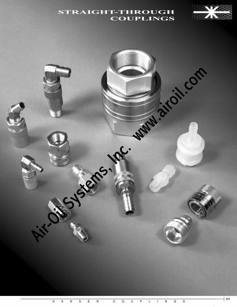
H A N S E N C O U P L I N G S53
ST
RA
IG
HT
-
TH
RO
UG
H
53
STRAIGHT-THROUGH COUPLINGS
Air-O
il Sy
stems,
Inc.
www.a
iroil.co
m

H A N S E N C O U P L I N G S54
ST
RA
IG
HT
-
TH
RO
UG
H
1/8
INC
H
1/4
INC
H
3/8
INC
H
1/2
INC
H
3/4
INC
H
1 IN
CH
1¼ IN
CH
1½ IN
CH
2 IN
CH
2½ IN
CH
BR
AS
S
ST
EE
L (
Plu
gs
On
ly)
STA
INL
ES
S S
TE
EL
(30
3)
PL
AS
TIC
(P
oly
pro
pyl
ene)
BA
LL
LO
CK
PL
AS
TIC
FIN
GE
RS
SL
EE
VE
LO
CK
SE
AL
MA
TE
RIA
LS
(V
ario
us)
DU
ST
CA
P/P
LU
G (
Vin
yl)
Coupling Series Page
1-ST 54
2-ST 54 ★
3-ST 54 ★
4-ST 54
6-ST 54 ▼
8-ST 54 ✧
10-ST 54 ✧
12-ST 54
16-ST 54
20-ST 54
P2-ST 56
P3-ST 56
GH 56
Flo-Temp 57
★ Socket dust plug only
▼ Socket dust plug and plug dust cap
✧ Plug dust cap only
Body SizeBody
MaterialLocking Mecha-nism
Options
Contents and Selector Chart
Air-O
il Sy
stems,
Inc.
www.a
iroil.co
m

H A N S E N C O U P L I N G S55
ST
RA
IG
HT
-
TH
RO
UG
H
Series ST straight-through couplings are designed for use where minimum pressure drop is required and valving is not needed. They are well suited for use on pressure wash, steam cleaning and carpet cleaning equipment, and many fluid transfer systems. Body sizes range from 1/8" to 2-1/2".Features• Ball lock • Manual operation • Smooth bore permits free flow of liquid or gas. • Male and female NPTF, BSPP and hose stem connections
Standard Materials • Brass or 303 stainless steel socket construction• Stainless steel springs, balls and retaining rings• Brass, zinc plated steel and 303 stainless steel plugs• High impulse heat treated 416 stainless steel plugs available
in 1/4" and 3/8" body sizes• Buna-N (Nitrile) seals
Options • Sleeve lock • Seals: Teflon (1-ST through 8-ST), Neoprene, Viton, Buna-N
and EPDM (See Elastomer Selection Guide, page 71)
Accessories• Dust caps and dust plugs for a limited number of sizes
(See page 68)
* Pressure ratings are for sockets and plugs with threaded end connections. Pressure ratings of couplings with hose stems may be significantly lower, and will depend on the type of hose and the method of clamping. Refer to hose manufacturer’s end connection pressure ratings. The best way to determine suitability for an application is to run pressure testing under controlled conditions.
*Rated Pressure Brass Socket Brass Socket Stainless Steel Body Brass Plug Steel Plug Socket & Plug
Series Size PSI BAR PSI BAR PSI BAR
1-ST 1/8" 2,800 193 3,400 234 4,200 290 2-ST 1/4" 5,200 359 5,500 379 7,500 517 3-ST 3/8" 2,800 193 4,200 290 6,300 434 4-ST 1/2" 2,200 152 3,500 241 3,600 248 6-ST 3/4" 1,700 117 2,100 145 3,000 207 8-ST 1" 1,300 90 2,000 138 2,000 138 10-ST 11/4" 1,700 117 2,700 186 2,200 152 12-ST 11/2" 1,400 97 2,200 152 2,500 172 16-ST 2" 1,400 97 2,200 152 1,500 103 20-ST 21/2" 900 62 1,500 103 – –
Series ST Straight-Through
Air-O
il Sy
stems,
Inc.
www.a
iroil.co
m

H A N S E N C O U P L I N G S56
ST
RA
IG
HT
-
TH
RO
UG
H
How to build a socket part number with options:
Example: 3-S21 - SL - 143
Standard Part Number from Part Number Tables
SL = Sleeve Lock1
Seal Material:115 = Teflon2
118 = Neoprene 143 = Viton 146 = Buna-N3
192 = EPDM
Notes: 1) The Sleeve Lock device prevents accidental disconnection.
2) Series ST couplings are designed for use with elastomer seals. Teflon is not an elastomer. It is rigid and not resilient. Couplings with Teflon seals may leak and/or be difficult to connect. Force to connect may be reduced by heating connected couplings in hot water; then, cooling before disconnecting. Teflon seals are available for Series 1-ST through 8-ST.
3) The 146 seal option may be specified for fuels and hydraulic fluids that cause standard Buna-N seals to swell escessively.
4) Some part numbers may be subject to minimum order quantities.
5) Some options may be available only by special quotation. Consult your Hansen distributor.
Hose Stem Connections
Female End Connections
Male End Connections
Series ST Straight-Through
Sockets
All dimensions in inches.
Body Part Number Thread Size Dimensions Size Brass Stainless NPTF BSPP A B Hex 1/8 1-S10 LL1-S10 1/8-27 — 1.06 0.69 0.50 1/8 1-S10BS LL1-S10BS — 1/8-28 1.00 0.69 0.56 1/4 2-S15 LL2-S15 1/4-18 — 1.72 0.94 0.81 1/4 2-S15BS LL2-S15BS — 1/4-19 1.56 0.94 0.81 3/8 3-S20 LL3-S20 3/8-18 — 1.75 1.13 1.00 3/8 3-S20BS LL3-S20BS — 3/8-19 1.62 1.13 1.00 1/2 4-S25 LL4-S25 1/2-14 — 2.03 1.31 1.13 1/2 4-S25BS LL4-S25BS — 1/2-14 1.80 1.31 1.13 3/4 6-S30 LL6-S30 3/4-14 — 2.22 1.69 1.44 3/4 6-S30BS — — 3/4-14 2.03 1.69 1.44 1 8-S35 — 1-111/2 — 2.53 2.00 1.75 1 8-S35BS — — 1-11 2.37 2.00 1.75
1/8 1-S11 LL1-S11 1/8-27 — 1.06 0.69 0.50 1/8 1-S11BS LL1-S11BS — 1/8-28 1.03 0.69 0.56 1/4 2-S16 LL2-S16 1/4-18 — 1.50 0.94 0.81 1/4 2-S16BS LL2-S16BS — 1/4-19 1.50 0.94 0.81 3/8 3-S21 LL3-S21 3/8-18 — 1.59 1.13 1.00 3/8 3-S21BS LL3-S21BS — 3/8-19 1.59 1.13 1.00 1/2 4-S26 LL4-S26 1/2-14 — 1.91 1.31 1.13 1/2 4-S26BS LL4-S26BS — 1/2-14 1.91 1.31 1.13 3/4 6-S31 LL6-S31 3/4-14 — 2.06 1.69 1.44 3/4 6-S31BS LL6-S31BS — 3/4-14 2.06 1.69 1.44 1 8-S36 LL8-S36 1-111/2 — 2.31 2.00 1.75 1 8-S36BS LL8-S36BS — 1-11 2.33 2.00 1.75 11/4 10-S41* LL10-S41 11/4-111/2 — 2.44 2.50 2.00 11/4 10-S41BS* — — 11/4-11 2.51 2.50 2.00 11/2 12-S46* LL12-S46 11/2-111/2 — 2.88 3.13 2.63 11/2 12-S46BS* LL12-S46BS — 11/2-11 2.88 3.13 2.63 2 16-S51* LL16-S51 2-111/2 — 3.09 3.75 3.00 2 16-S51BS* LL16-S51BS — 2-11 3.30 3.75 3.00 21/2 20-S56* — 21/2-8 — 3.44 4.50 3.50 * With Steel Sleeve
Body Part Number Thread Size Dimensions Size Brass Stainless NPTF BSPP A B Hex
1/8 1-S12 LL1-S12 3/16" 1.41 0.69 1/8 1-S17 LL1-S17 1/4" 1.41 0.69 1/4 2-S17 LL2-S17 1/4" 2.10 0.94 3/8 3-S22 LL3-S22 3/8" 2.09 1.13 1/2 4-S27 LL4-S27 1/2" 2.19 1.31 3/4 6-S32 LL6-S32 3/4" 3.19 1.69 1 8-S37 LL8-S37 1" 3.32 2.00
Body Part Number Dimensions Size Brass Stainless Hose I.D. A B
Air-O
il Sy
stems,
Inc.
www.a
iroil.co
m

H A N S E N C O U P L I N G S57
ST
RA
IG
HT
-
TH
RO
UG
H
Female End Connections
Male End Connections
Hose Stem Connections
Any plug will connect with any socket in the same series (same body size)
Series ST Straight-Through
Plugs Body Part Number Thread Size Dimensions Size Brass Steel Stainless NPTF BSPP C D Hex
1/8 B1-T11 1-T11 LL1-T11 1/8-27 — 1.00 0.58 0.50 1/8 B1-T11BS — LL1-T11BS — 1/8-28 0.97 0.65 0.56 1/4 B2-T16 2-T16 LL2-T16 1/4-18 — 1.50 0.79 0.69 1/4 — — HL2-T16* 1/4-18 — 1.50 0.79 0.69 1/4 B2-T16BS 2-T16BS LL2-T16BS — 1/4-19 1.45 0.87 0.75 3/8 B3-T21 3-T21 LL3-T21 3/8-18 — 1.63 0.94 0.81 3/8 — — HL3-T21* 3/8-18 — 1.63 0.94 0.81 3/8 B3-T21BS 3-T21BS LL3-T21BS — 3/8-19 1.63 1.01 0.88 1/2 B4-T26 4-T26 LL4-T26 1/2-14 — 1.94 1.15 1.00 1/2 B4-T26BS 4-T26BS LL4-T26BS — 1/2-14 1.92 1.23 1.06 3/4 B6-T31 6-T31 LL6-T31 3/4-14 — 2.06 1.37 1.19 3/4 B6-T31BS — LL6-T31BS — 3/4-14 2.01 1.52 1.31 1 B8-T36 8-T36 LL8-T36 1-111/2 — 2.21 1.80 1.56 1 B8-T36BS 8-T36BS LL8-T36BS — 1-11 2.23 1.80 1.56 11/4 B10-T41 10-T41 LL10-T41 11/4-111/2 — 2.34 2.31 2.00 11/4 B10-T41BS — — — 11/4-11 2.44 2.31 2.00 11/2 B12-T46 12-T46 LL12-T46 11/2-111/2 — 2.88 2.60 2.25 11/2 B12-T46BS — — — 11/2-11 2.88 2.60 2.25 2 B16-T51 16-T51 — 2-111/2 — 3.03 3.18 2.75 2 B16-T51BS — — — 2-11 3.25 3.18 2.75 21/2 B20-T56 20-T56 — 21/2-8 — 3.37 3.75 3.25
*High impulse heat treated 416 stainless steel
Body Part Number Thread Size Dimensions Size Brass Steel Stainless NPTF BSPP C D Hex
1/8 B1-T12 — LL1-T12 3/16" 1.28 0.44 1/8 B1-T17 — LL1-T17 1/4" 1.28 0.44 1/4 B2-T17 2-T17 LL2-T17 1/4" 1.93 0.56 3/8 B3-T22 3-T22 LL3-T22 3/8" 2.09 0.69 1/2 B4-T27 4-T27 LL4-T27 1/2" 2.17 0.88 3/4 B6-T32 6-T32 LL6-T32 3/4" 3.17 1.19 1 B8-T37 8-T37 — 1" 3.28 1.50
Body Part Number Dimensions Size Brass Steel Stainless Hose I.D. C D
1/8 B1-T10 1-T10 LL1-T10 1/8-27 — 1.09 0.51 0.44 1/8 B1-T10BS — — — 1/8-28 0.89 0.65 0.56 1/8 B1-T15 1-T15 — 1/4-18 — 1.25 0.65 0.56 1/4 B2-T15 2-T15 LL2-T15 1/4-18 — 1.61 0.65 0.56 1/4 — — HL2-T15* 1/4-18 — 1.61 0.65 0.56 1/4 B2-T15BS 2-T15BS LL2-T15BS — 1/4-19 1.35 0.87 0.75 3/8 B3-T20 3-T20 LL3-T20 3/8-18 — 1.69 0.79 0.69 3/8 — — HL3-T20* 3/8-18 — 1.69 0.79 0.69 3/8 B3-T20BS 3-T20BS LL3-T20BS — 3/8-19 1.50 1.01 0.88 1/2 B4-T25 4-T25 LL4-T25 1/2-14 — 2.03 1.01 0.88 1/2 B4-T25BS 4-T25BS LL4-T25BS — 1/2-14 1.77 1.15 1.00 3/4 B6-T30 6-T30 LL6-T30 3/4-14 — 2.25 1.23 1.06 3/4 B6-T30BS — LL6-T30BS — 3/4-14 2.00 1.44 1.25 1 B8-T35 8-T35 LL8-T35 1-111/2 — 2.53 1.59 1.38 1 B8-T35BS — — — 1-11 2.30 2.02 1.75 11/4 B10-T40 10-T40 LL10-T40 11/4-111/2 — 2.72 2.02 1.75 11/4 B10-T40BS — — — 11/4-11 2.50 2.31 2.00 11/2 B12-T45 12-T45 — 11/2-111/2 — 3.31 2.60 2.25 11/2 B12-T45BS — — — 11/2-11 3.06 2.60 2.25 2 B16-T50 16-T50 LL16-T50 2-111/2 — 3.50 3.18 2.75 2 — — LL16-T50BS — 2-11 3.50 3.18 2.75 21/2 B20-T55 — — 21/2-8 — 3.97 3.75 3.25
*High impulse heat treated 416 stainless steel
All dimensions in inches.
Air-O
il Sy
stems,
Inc.
www.a
iroil.co
m

H A N S E N C O U P L I N G S58
ST
RA
IG
HT
-
TH
RO
UG
H
Series P-2ST and P3-ST cou-plings are designed for use with medical equipment. They can also be used in a variety of low pressure fluid transfer applica-tions. Features
• Interchange with 2-ST and 3-ST• Excellent chemical resistance• Light weight • Low cost
Standard Materials
• Polypropylene construction • Buna-N (Nitrile) seals
Rated PressureTemperature* PSI BAR
75° 110 8
200° 30 2
*235°F maximum sterilization temperature
Hose Dimensions Series Part Number I.D. A B P2-ST P2-STS-25H 1/4" 2.07 1.12Each P2-ST socket uses one Part No. 902-7 o-ring. P3-ST P3-STS-37H 3/8" 2.61 1.37Each P3-ST socket uses one Part No. 902-10-199 o-ring.
Dimensions Series Part Number Thread Size C D HEX P2-ST P2-STP-25M 1/4-18 NPTF 1.56 0.65 0.56 P3-ST P3-STP-25M 1/4-18 NPTF 1.69 0.79 0.69 P3-ST P3-STP-37M 3/8-18 NPTF 1.69 0.79 0.69
Hose Dimensions Series Part Number I.D. C D P3-ST P3-STP-37H 3/8" 2.16 0.79
SOCKETS
PLUGS
Series GH couplings are designed for water service where hoses are connected and disconnected frequently. They are available with garden hose threads and 3/4" pipe threads. Sockets are available without valves for maximum flow and with valves for convenience of operation.
Features
• Durable brass construction • Ball lock • High quality Buna-N seals • Straight-through or one-way
shut-off
Standard Materials
• Brass plug and socket bodies• Nickel plated brass sleeve• Stainless steel balls and
springs• Buna-N o-ring and washer• Plastic (acetal) valve
Female Dimensions Part No. Hose Thread A B GHS-12 Non-valved 3/4-111/2 1.19 1.19 GHS-12-V Valved 3/4-111/2 1.19 1.19
SOCKETS
PLUGS
Female Dimensions Part No. Pipe Thread A B HEX 8-GHS-75FS Non-valved 3/4-14 NPTF 1.18 1.25 1.13 8-GHS-75FS-V Valved 3/4-14 NPTF 1.18 1.25 1.13
Male Dimensions Part No. Hose Thread C D GHP-11 3/4-111/2 1.30 1.06
Male Dimensions Part No. Pipe Thread C D HEX 8-GHP-75M 3/4-14 NPTF 1.66 1.18 1.06
Rated Pressure PSI BAR
200 14
Series P2-ST & P3-ST
Series GH Garden Hose
Air-O
il Sy
stems,
Inc.
www.a
iroil.co
m

H A N S E N C O U P L I N G S59
ST
RA
IG
HT
-
TH
RO
UG
H
Replacement Parts Part Number
Description Series 200 Series 300 Series 500
Seal WFT-200-228 WFT-300-228 WFT-500-228Valve VFT-200 VFT-300 VFT-500Valve O-Ring 902-3-143 903-8-143 914-3-143Valve Spring VSFT-200 VS-3000 VSFT-500
Flo-Temp couplings provide the flow needed to cool or heat injec-tion molds and die casting dies. Sockets are available non-valved for maximum flow, and valved to prevent fluid loss when discon-nected. Flo-Temp couplings can be used with water-glycol, hot water and hot oil. Body sizes are 1/4", 3/8" and 1/2".
Features
• Non-valved straight-through models for maximum flow
• Valved sockets for automatic shut-off when line is disconnected
• Sockets with straight, 90° and 45° hose stems and without hose stem
• Brass plugs with male pipe thread for recessed mounting to avoid damage to plugs when molds are being changed or stored
Standard Materials
• Brass socket construction
• Stainless steel springs and locking balls
• Viton seals (-30°F to +450°F)
• Brass plugs
Rated Pressure Series PSI BAR
200/300/500 200 14
Series FLO-TEMP 200/300/500
FLOW RATE, gpm(Water)
Air-O
il Sy
stems,
Inc.
www.a
iroil.co
m

H A N S E N C O U P L I N G S60
ST
RA
IG
HT
-
TH
RO
UG
H
PLUGS
*Part numbers with HP suffix have push-on hose barb. All other FTS part numbers have standard hose barb.
SOCKETS
Series FLO-TEMP 200/300/500
Without Hose Stem
Male Pipe Thread
90° Hose Stem
45° Hose Stem
Female Pipe Thread
Straight Hose Stem
Non-Valved Valved A B Hex1/4 FTS-214 FTS-214V 1/4" 1.36 0.67 2.171/4 FTS-214HP* FTS-214VHP* 1/4" 1.18 0.67 1.761/4 FTS-215 FTS-215V 5/16" 1.18 0.67 1.761/4 FTS-216 FTS-216V 3/8" 1.17 0.67 1.761/4 FTS-216HP* FTS-216VHP* 3/8" 1.17 0.67 1.763/8 FTS-316 FTS-316V 3/8" 1.60 0.88 2.433/8 FTS-316HP* FTS-316VHP* 3/8" 1.60 0.88 2.433/8 FTS-318 FTS-318V 1/2" 1.60 0.88 2.433/8 FTS-318HP* FTS-318VHP* 1/2" 1.60 0.88 2.43
Dimensions (inches)BodySize
(inch)HoseI.D.
Part Number
A B Hex1/4 LNFT-200 1.68 0.67 0.56 1/8-273/8 LNFT-300 2.18 0.89 0.75 1/4-181/2 LNFT-500 2.00 1.17 1.13 1/2-14
BodySize
(inch) Part NumberDimensions (inches)
ThreadSize
NPTF
Non-Valved Valved A B Hex1/4 FTS-224 FTS-224V 1/4" 1.17 0.67 2.401/4 FTS-224HP* FTS-224VHP* 1/4" 1.17 0.67 2.401/4 FTS-225 FTS-225V 5/16" 1.17 0.67 2.401/4 FTS-226 FTS-226V 3/8" 1.17 0.67 2.41/4 FTS-226HP* FTS-226VHP* 3/8" 1.17 0.67 2.403/8 FTS-326 FTS-326V 3/8" 1.80 0.90 3.703/8 FTS-326HP* FTS-326VHP* 3/8" 1.80 0.90 3.173/8 FTS-328 FTS-328V 1/2" 1.80 0.90 3.173/8 FTS-328HP* FTS-328VHP* 1/2" 1.80 0.90 3.17
Dimensions (inches)BodySize
(inch)HoseI.D.
Part Number
Non-Valved Valved A B Hex1/4 FTS-204 FTS-204V 1/4" 1.20 0.67 2.251/4 FTS-204HP* FTS-204VHP* 1/4" 1.20 0.67 2.091/4 FTS-205 FTS-205V 5/16" 1.20 0.67 2.091/4 FTS-206 FTS-206V 3/8" 1.20 0.67 2.251/4 FTS-206HP* FTS-206VHP* 3/8" 1.20 0.67 2.343/8 FTS-306 FTS-306V 3/8" 1.6 0.91 2.683/8 FTS-306HP* FTS-306VHP* 3/8" 1.61 0.89 2.753/8 FTS-308 FTS-308V 1/2" 1.61 0.88 2.823/8 FTS-308HP* FTS-308VHP* 1/2" 1.61 0.88 2.821/2 FTS-504 FTS-504V 1/2" 2.25 1.18 3.421/2 FTS-504HP* FTS-504VHP* 1/2" 2.25 1.18 3.621/2 FTS-506 FTS-506V 3/4" 2.22 1.18 3.851/2 FTS-506HP* FTS-506VHP* 3/4" 2.22 1.18 4.35
Dimensions (inches)BodySize
(inch)HoseI.D.
Part Number
Air-O
il Sy
stems,
Inc.
www.a
iroil.co
m

H A N S E N C O U P L I N G S61
AC
CE
SS
OR
IES
61
GAS COUPLINGS
Air-O
il Sy
stems,
Inc.
www.a
iroil.co
m

H A N S E N C O U P L I N G S62
Gas-Mate couplings are one-way shut-off safety couplings designed for use with various fuel gases. Body sizes are 3/8", 1/2", 3/4", 1" and 1¼".Features• Connect and disconnect without
using wrenches
• Automatic shut-off when plug is removed from socket
• In case of fire, heat-sensitive plug allows socket valve to close, stopping gas flow
• Push-to-connect (1¼" only)
For connection of gas cookingappliances and other gas-fireddevices.
CSA* design certified, in both theUnited States and Canada, fornatural gas, manufactured gas,liquified petroleum and LP gas-airmixtures at pressures not in excess of 1/2 psig (3.5 kPa)
*CANADIAN STANDARDS ASSOCIATION
Complies with the requirements ofANSI Z21.41 & CSA 6.9.
Standard Materials
• Brass construction
• Stainless steel locking balls
• Viton socket o-ring
• Valve actuator soldered to plug with low melting temperature alloy.
Accessories
• Dust caps and dust plugs (See page 68.)
Sockets Plugs Thread Dimensions Body Size Across Size Part No. NPTF A B Flats 3/8" 100-006 3/8-18 2.44 1.13 1.00 1/2" 100-008 1/2-14 2.84 1.38 1.13 3/4" 100-010 3/4-14 3.17 1.75 1.50 1" 100-012 1-11½ 3.94 2.13 1.75
Thread Body Size Dimensions Size Part No. NPTF C D HEX 3/8" 100-506 3/8-18 1.59 0.94 0.81 1/2" 100-508 1/2-14 1.94 1.16 1.00 3/4" 100-510 3/4-14 2.06 1.52 1.31 1" 100-512 1-11½ 2.47 1.73 1.50
Thread Body Size Dimensions Size Part No. NPTF C D HEX1¼" GMP1250F 1¼-11½ 2.44 2.16 1.88
Thread Dimensions Body Size Size Part No. NPTF A B Hex1¼" GMS1250FH 1¼-11½ 4.15 2.28 2.00
3/8" to 1" Gas-Mate 11/4" Gas-Mate
Capacities Body Socket Plug Capacity* Socket O-Ring Size Part No. Part No. BTU/hr Part No. 3/8" 100-006 100-506 60,000 914-3-143M 1/2" 100-008 100-508 90,000 902-14-143M 3/4" 100-010 100-510 245,000 902-18-143M 1" 100-012 100-512 310,000 902-23-143M 1¼" GMS1250FH GMP1250F 500,000 914-26-143M* Capacity is based on natural gas having a specific gravity of 0.64 and a heat capacity of
1,000 BTU per cubic foot. Inlet pressure is 12 inches water column and the pressure drop is 0.3 inch water column.
Series Gas-MateG
AS
C
OU
PL
IN
GS
Air-O
il Sy
stems,
Inc.
www.a
iroil.co
m

H A N S E N C O U P L I N G S63
Air-O
il Sy
stems,
Inc.
www.a
iroil.co
m

H A N S E N C O U P L I N G S64
AC
CE
SS
OR
IES
Series FS Flow Sensors are designed to protect personnel and property in case of hose failure in compliance with Federal Safety Regulations. Flow Sensors are intended for use with compressed air.
Features
• Automatically shuts off air flow to ruptured hose
• Reduces risk of injury or damage from hose whip
• Automatically resets after failure correction
• 250 psig pressure rating (all sizes)
• Low pressure drop
• Operates in any orientation
• Compact design, economical, tamper-resistant
Standard Materials
• Brass body
• Acetal valve (1/4" - 1")
• Brass valve (1½")
• Stainless steel valve spring
Flow Data - The graph below left indicates the minimum inlet pressure for various hose lengths. Each Flow Sensor has a shut-off flow rating dependent upon inlet pressure. The length of hose and fitting size are critical in the proper operation of the valve. For example, with the B8-FS-50F-8 Flow Sensor, the hose I.D. must be 1/2" using only 1/2" pipe thread end fittings. Thirty feet of hose requires at least 20 psig inlet pressure; fifty feet of hose requires at least 28 psig inlet pressure; and seventy-five feet of hose requires at least 36 psig inlet pressure. Inlet pressures lower than those indicated on the curves below will not guarantee protection in case of hose failure. Valve shut-off occurs only when flow exceeds the flow rating for the inlet pressure. If hose lengths greater than 75 feet are required, a 1/2" size or larger Flow Sensor must be installed on the inlet end of each 75-foot section, and a correspondingly higher inlet pressure must be supplied for proper operation of the Flow Sensor to assure safety.
All Flow Sensors have a pressure drop of approximately 2 psid at 80% of shut-off flow.
Series FS Flow Sensor
All dimensions in inches.
Air-O
il Sy
stems,
Inc.
www.a
iroil.co
m
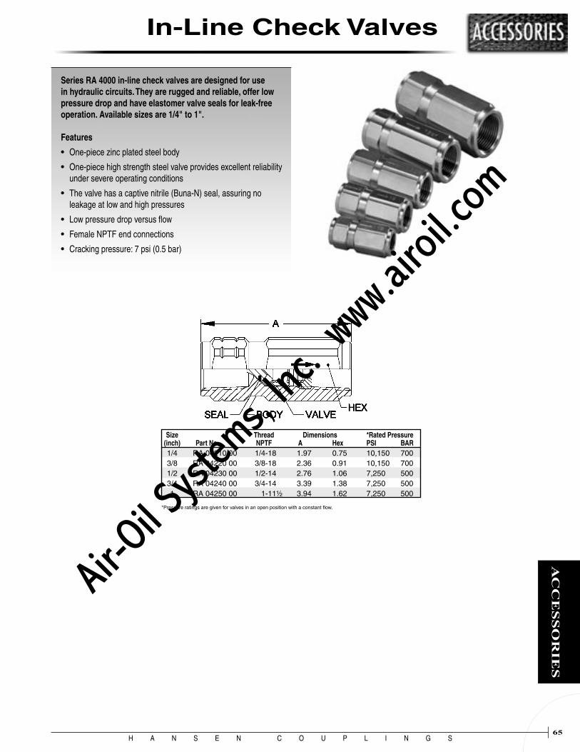
H A N S E N C O U P L I N G S65
AC
CE
SS
OR
IES
In-Line Check Valves
Series RA 4000 in-line check valves are designed for use in hydraulic circuits. They are rugged and reliable, offer low pressure drop and have elastomer valve seals for leak-free operation. Available sizes are 1/4" to 1". Features
• One-piece zinc plated steel body
• One-piece high strength steel valve provides excellent reliability under severe operating conditions
• The valve has a captive nitrile (Buna-N) seal, assuring no leakage at low and high pressures
• Low pressure drop versus flow
• Female NPTF end connections
• Cracking pressure: 7 psi (0.5 bar)
Size Thread Dimensions *Rated Pressure (inch) Part No. NPTF A Hex PSI BAR 1/4 RA 04210 00 1/4-18 1.97 0.75 10,150 700 3/8 RA 04220 00 3/8-18 2.36 0.91 10,150 700 1/2 RA 04230 00 1/2-14 2.76 1.06 7,250 500 3/4 RA 04240 00 3/4-14 3.39 1.38 7,250 500 1 RA 04250 00 1-11½ 3.94 1.62 7,250 500
*Pressure ratings are given for valves in an open position with a constant flow.
Air-O
il Sy
stems,
Inc.
www.a
iroil.co
m

H A N S E N C O U P L I N G S66
AC
CE
SS
OR
IES
Fittings
1/8-27 NPTF Hose Part No. I.D. O.D. MPT FPT
Series A 3/16" 7/16" 1A0 — 3/16" 1/2" 1A3 —
Series B 1/4" 15/32" 1B1 — 1/4" 1/2" 1B3 — 1/4" 9/16" 1B5 — 1/4" 5/8" 1B7 — 1/4" 3/4" 1B11 —
Hose Clamps (Brass) • Compression Type, Reusable
1/4-18 NPTF Hose Part No. I.D. O.D. MPT FPT
Series A 3/16" 7/16" 2A0 — 3/16" 1/2" 2A3 —
Series B 1/4" 15/32" 2B1 3B1 1/4" 1/2" 2B3 3B3 1/4" 9/16" 2B5 3B5 1/4" 5/8" 2B7 3B7 1/4" 11/16" 2B9 3B9
Series C 5/16" 9/16" 2C5 – 5/16" 5/8" 2C7 3C7 5/16" 11/16" 2C9 –
Series D 3/8" 9/16" 2D5 3D5 3/8" 5/8" 2D7 3D7 3/8" 11/16" 2D9 3D9 3/8" 3/4" 2D11 3D11 3/8" 13/16" 2D13 3D13 3/8" 7/8" 2D15 3D15
Series P 1/2" 13/16" 2P13 — 1/2" 7/8" 2P15 — 1/2" 15/16" 2P17 — 1/2" 1" 2P19 —
3/8-18 NPTF Hose Part No. I.D. O.D. MPT FPT
Series B 1/4" 15/32" 4B1 — 1/4" 1/2" 4B3 — 1/4" 9/16" 4B5 — 1/4" 5/8" 4B7 —
Series C 5/16" 5/8" 4C7 — 5/16" 11/16" 4C9 —
Series D 3/8" 9/16" 4D5 5D5 3/8" 5/8" 4D7 5D7 3/8" 11/16" 4D9 5D9 3/8" 3/4" 4D11 5D11 3/8" 13/16" 4D13 5D13 3/8" 7/8" 4D15 5D15
Series P 1/2" 13/16" 4P13 — 1/2" 7/8" 4P15 — 1/2" 15/16" 4P17 — 1/2" 1" 4P19 —
1/2-14 NPTF Hose Part No. I.D. O.D. MPT FPT
Series P 1/2" 13/16" 6P13 7P13 1/2" 7/8" 6P15 7P15 1/2" 15/16" 6P17 7P17 1/2" 1" 6P19 7P19
Series R 3/4" 11/8" 6R23 — 3/4" 13/16" 6R25 — 3/4" 1¼" 6R27 —
3/4-14 NPTF Hose Part No. I.D. O.D. MPT FPT
Series P 1/2" 13/16" 8P13 — 1/2" 7/8" 8P15 — 1/2" 15/16" 8P17 — 1/2" 1" 8P19 —
Series R 3/4" 11/8" 8R23 — 3/4" 13/16" 8R25 — 3/4" 1¼" 8R27 —
1-11½ NPTF Hose Part No. I.D. O.D. MPT FPT
Series R 3/4" 11/8" 10R23 — 3/4" 13/16" 10R25 — 3/4" 1¼" 10R27 —
9/16-18 Straight Thread Hose Part I.D. O.D. No.Series A 3/16" 7/16" 4LA0* 3/16" 7/16" 4RA0 3/16" 1/2" 4LA3* 3/16" 1/2" 4RA3 Series B 1/4" 15/32" 4RB1 1/4" 1/2" 4LB3* 1/4" 1/2" 4RB3 1/4" 9/16" 4LB5* 1/4" 9/16" 4RB5 1/4" 5/8" 4RB7 Series D 3/8" 5/8" 4RD7 3/8" 11/16" 4RD9 3/8" 3/4" 4RD11
* Left-hand thread for acetylene service
7/16-20 Straight Thread Hose Part I.D. O.D. No.Series B 1/4" 15/32" 720B1 1/4" 1/2" 720B3 1/4" 9/16" 720B5 1/4" 5/8" 720B7
5/8-18 Straight Thread Hose Part I.D. O.D. No.Series D 3/8" 5/8" 2FD7 3/8" 11/16" 2FD9 3/8" 3/4" 2FD11
9/16-18 Straight Thread Hose Part I.D. O.D. No.Series D 3/8" 5/8" 4FD7 3/8" 11/16" 4FD9 3/8" 3/4" 4FD11 3/8" 7/8" 4FD15
3/4-16 Straight Thread Hose Part I.D. O.D. No.Series P 1/2" 13/16" 1216P13 1/2" 7/8" 1216P15
With Brass Male Swivel Insert – External Seat (inverted flare) for use with paint spray and oxygen fittings, etc. (Will accept 37° or 45° flare.). The Swivel Nut Hose Clamp is similar to the standard hose clamp, but includes a swivel nut.
With Steel Female Swivel Insert, 37° Female Flare, for use with flared tube fittings.
Swivel Nut Hose Clamps (Brass) • Compression Type, Reusable
1/4-18 NPSM Straight Thread Hose Part I.D. O.D. No.Series B 1/4" 15/32" 5RB1 1/4" 1/2" 5RB3 1/4" 9/16" 5RB5 1/4" 5/8" 5RB7 Series C 5/16" 5/8" 5RC7 Series D 3/8" 5/8" 5RD7 3/8" 11/16" 5RD9 3/8" 3/4" 5RD11
Male Pipe Thread (MPT) Female Pipe Thread (FPT)
Air-O
il Sy
stems,
Inc.
www.a
iroil.co
m

H A N S E N C O U P L I N G S67
AC
CE
SS
OR
IES
Fittings
Hose Stems
Splicers (Brass)
Unions (Brass) Adapters
Hose Stem-to-Male Pipe Thread Hose Thread Part No. I.D. NPTF Brass Stainless 3/16" 1/8-27 SN16 LLS16 1/4" 1/8-27 SN17 — 3/8" 1/8-27 SN18 — 3/16" 1/4-18 S19 — 1/4" 1/4-18 S20 LLS20 5/16" 1/4-18 S205 — 3/8" 1/4-18 S21 — 1/2" 1/4-18 S22 — 1/4" 3/8-18 S23 — 3/8" 3/8-18 S24 LLS24 1/2" 3/8-18 S25 — 1/2" 1/2-14 S26 LLS26 3/4" 3/4-14 — LLS30 1" 1-111/2 — LLS35
Hose Stem-to-Hose Stem Hose I.D. Part No. 3/16" HS-30 1/4" HS-31 5/16" HS-32 3/8" HS-33 1/2" HS-34
Hose Clamp-to-Hose Clamp Hose I.D. Hose O.D. Part No. 1/4" 15/32" HSC-B1 1/4" 1/2" HSC-B3 1/4" 5/8" HSC-B7 5/16" 5/8" HSC-C7 5/16" 11/16" HSC-C9 3/8" 9/16" HSC-D5 3/8" 5/8" HSC-D7 3/8" 11/16" HSC-D9 3/8" 3/4" HSC-D11
Part No. H25MHU Part No. HHU25M1/4" Male Pipe Thread 1/4" Male Pipe Thread Union Half consists of Union Half H25HMU01 body and 902-8 o-ring.
Part No. H25HHU Part No. HHU25F1/4" Hose Stem 1/4" Female Pipe Union Half consists Thread Union Half of H25HHU01 stem, 902-8 o-ring and HUSN1 sleeve
Part No. H37HHU Part No. HHU37H3/8" Hose Stem 3/8" Hose Stem Union Half consists Union Half of H37HHU01 stem, 902-8 o-ring and HUSN1 sleeve Any union half shown on the left can be used with any union half shown on the right.
Oxygen Adapter (Brass) Part No. Thread Size 9-MBR 1/4-18 NPTF x 9/16-18 Right Hand
Pipe-to-Pipe Adapter (Brass) Part No. Thread Size 18-MAM 1/8-27 NPTF x 1/4-18 NPTF 19-MBM 1/4-18 NPTF x 1/4-18 NPTF 20-MBM 1/4-18 NPTF x 3/8-18 NPTF
Flare-to-Pipe Adapter (Stainless)
Part No. Thread Size A-402 7/16-20 (1/4" 45° Flare) x 1/4-18 NPTF
Flare-to-Flare Adapter (Stainless)
Part No. Thread Size A-394 7/16-20 (1/4" 45° Flare) Both Ends A-375 5/8-18 (3/8" 45° Flare) Both Ends
All stainless steel fittings listed on this page are machined from Type 303 stainless steel bar stock.
Air-O
il Sy
stems,
Inc.
www.a
iroil.co
m

H A N S E N C O U P L I N G S68
AC
CE
SS
OR
IES
Dust Caps and Dust Plugs
The use of dust caps and dust plugs keeps mating surfaces of disconnected couplings clean, and extends the useful life of seals and mechanical components. Plug dust caps prevent damage to plugs that could make a coupling unusable. All dust caps and plugs offered for Hansen couplings are listed on this page and the next.
HK-Style Dust Caps and Plugs
Vinyl Socket Dust Plug
Vinyl Plug Dust Cap
Metal Plug Dust Cap
Metal Socket Dust Plug
Coupling Plug Dust Cap Part No. Socket Dust Plug Part No.
Type Series Metal Vinyl Metal Vinyl
1-HK PDC-1-HK* P-PDC-1-HK SDC-1-HK* P-SDC-1-HK
2-HK PDC-2-HK* P-PDC-2-HK SDC-2-HK* P-SDC-2-HK
3-HK PDC-3-HK* P-PDC-3-HK SDC-3-HK* P-SDC-3-HK
4-HK PDC-4-HK** P-PDC-4-HK SDC-4-HK** P-SDC-4-HK
6-HK PDC-6-HK** P-PDC-6-HK SDC-6-HK** P-SDC-6-HK
8-HK PDC-8-HK** P-PDC-8-HK SDC-8-HK** P-SDC-8-HK
12-HK PDC-12-HK** — SDC-12-HK** —
20-HK PDC- 20-HK** — SDC-20-HK** —
UP10 — P-PDC-2-HK — P-SDC-2-HK
2-HKIG — P-PDC-2-HK — —
2-HKIL — P-PDC-2-HK — —
3000 PDC-3000* — SDC-3000* P-SDC-1-HK
4000 — — — P-SDC-2-HK
5000 — P-PDC-2-HK — —
6000 — P-PDC-3-HK — —
1000 — — — P-SDC-1-HK
400 — — — P-SDC-2-HK
100 — P-PDC-1-HK — P-SDC-1-HK
600 — P-PDC-1-HK — P-SDC-1-HK
700 — P-PDC-1-HK — P-SDC-1-HK
2-RL — P-PDC-1-HK — P-SDC-1-HK
3-RL — P-PDC-2-HK — P-SDC-2-HK
2-ST — — — P-SDC-1-HK
3-ST — — — P-SDC-2-HK
6-ST — P-PDC-4-HK — P-SDC-4-HK
8-ST — P-PDC-6-HK — —
10-ST — P-PDC-8-HK — —
3/8” PDC-2-HK* P-PDC-2-HK SDC-2-HK* P-SDC-2-HK
1/2” PDC-3-HK* P-PDC-3-HK SDC-3-HK* P-SDC-3-HK
3/4” PDC-4-HK** P-PDC-4-HK SDC-4-HK** P-SDC-4-HK
1” PDC-6-HK** P-PDC-6-HK SDC-6-HK** P-SDC-6-HK
*Brass **Aluminum
Gas
-Mat
e S
trai
gh
t-
On
e-W
ay
Two
-Way
Th
rou
ghAi
r-Oil Sy
stems,
Inc.
www.a
iroil.co
m

H A N S E N C O U P L I N G S69
AC
CE
SS
OR
IES
Dust Caps and Dust Plugs
Series HA 15000 ISO 7241-1 Series A
Series QA 29000 Flat Face
Series 96 Wing Nut
Series WA 56000 10,000 psi Thread-to-Connect
Series WA 10000 Refrigerant and Liquid Transfer
Air-O
il Sy
stems,
Inc.
www.a
iroil.co
m

H A N S E N C O U P L I N G S70
AC
CE
SS
OR
IES
The Flex-Air Fitting is designed to rotate 360° at up to a 75° angle. The Flex-Air Fitting helps to alleviate Carpal Tunnel Syndrome and other stress related injuries in the workplace. Features
• Unique design provides free 360° rotation with up to a 75° angle of rotation in any direction
• Many styles and sizes available
• 145 psig (10 Bar) pressure rating (all models)
Benefits
• Provides flexibility of tool position to help alleviate Carpal Tunnel Syndrome and back stress resulting in fewer lost-time injuries
• Minimizes paint damage
• Prevents kinking of air supply hose
Applications
• Assembly air lines in automotive, electronic and other industries
• Mechanical joints for robotics
• Vibration isolation
• Commercial and residential construction
Standard Materials
• Integrated steel/polyurethane construction
• Steel balls
• Buna-N (Nitrile) seals
• Thread sealant standard on male NPTs
Part Number Description Inside Dia. FA25F-25M 1/4" NPT Female x 1/4" NPT Male 0.2" (5 mm) FA25F-37M 1/4" NPT Female x 3/8" NPT Male 0.3" (7.5 mm) FA37F-37M 3/8" NPT Female x 3/8" NPT Male 0.3" (7.5 mm)
Flex-Air Fittings
Part Number Description Inside Dia. FA25M-25M 1/4" NPT Male x 1/4" NPT Male 0.2" (5 mm) FA37M-37M 3/8" NPT Female x 3/8" NPT Male 0.3" (7.5 mm)
Part Number Description Inside Dia. FA25P-25M 1/4" Industrial Interchange x 1/4" NPT Male 0.2" (5 mm) FA37P-25M 3/8" Industrial Interchange x 1/4" NPT Male 0.3" (7.5 mm)
Part Number Description Inside Dia. FA25AR-25M ARO210 Interchange x 1/4" NPT Male 0.2" (5 mm)
Part Number Description Inside Dia. FA37H-37M 3/8" Barb x 3/8" NPT Male 0.3" (7.5 mm)
Part Number Description Inside Dia. FA3RL-37M 3/8" RL Plug x 3/8" NPT Male 0.3" (7.5 mm)
Part Number Description Inside Dia. FA25LI-25M Lincoln Interchange x 1/4" NPT Male 0.2" (5 mm)
Air-O
il Sy
stems,
Inc.
www.a
iroil.co
m

H A N S E N C O U P L I N G S71
Elastomer Selection Guide
Select seals compatible with the service intended for the couplings. Allowance must be made for the kind of fluid to be conveyed and its temperature. Chemically active fluids will destroy some seal materials. Certain seals withstand high temperatures, whereas others cannot. Use this elastomer selection guide to find the appropriate seal. NOTE: Elastomer or seal material listed as “Standard” is furnished in most Hansen couplings. Elastomers designated as “-118”, “-146”, “-192”, etc., are available as optional seal material for some couplings. Other seal materials available upon request to suit requirements. Consult a Hansen Distributor.
NOTE: The following information is accurate to the best of our knowledge; however, since service conditions vary so widely, it is intended as a guide only and is not a guarantee.
FLUID HANSEN ELASTOMERAir (to 200° F) .......................................................................StandardAir (above 200°F) ................................................................. -143Acetone ................................................................................ -192*Acetylene ..............................................................................StandardAlcohol, Ethyl ........................................................................ -192*Alcohol, Methyl .....................................................................StandardAlkalies ................................................................................. -192*Ammonia, Anhydrous ...........................................................StandardAmmonium Hydroxide .......................................................... -192*Aroclor .................................................................................. -143Brake Fluid, Non-Petroleum Based ...................................... -192*Butane .................................................................................. -146Carbon Dioxide .....................................................................StandardCarbon Tetrachloride ............................................................ -143Cellulube ............................................................................... -192*Creosote ...............................................................................StandardDiesel Fuel ............................................................................ -146Diester Lubricants ................................................................ -143Ethane .................................................................................. -146Ethanol ................................................................................. -192*Ethylene Glycol ..................................................................... -192*Freon (most varieties) ........................................................... -118Gasoline, Aromatic & Non-Aromatic ..................................... -143Glycerin ................................................................................StandardHelium ..................................................................................StandardHeptane ................................................................................ -146Hexane ................................................................................. -146Houghto-Safe Series 200, 600, 5000 ...................................StandardHoughto-Safe Series 1000 ................................................... -192*Hydraulic Fluid, Petroleum-based with .................................Standard Aniline Point above 160° F Hydrolube .............................................................................StandardJet Fuel (to 250° F) ............................................................... -146Jet Fuel (above 250° F) ........................................................ -143
FLUID HANSEN ELASTOMERKerosene .............................................................................. -146Lindol .................................................................................... -192*L.P. Gases .............................................................................StandardMethane ................................................................................ -146Methanol ...............................................................................StandardMethyl Ethyl Ketone .............................................................. -192*Methyl Iso-Butyl Ketone ........................................................ -192*MIL-H-5606A ........................................................................StandardMineral Spirits ....................................................................... -146 Natural Gas ..........................................................................StandardNitrogen ................................................................................StandardOctane .................................................................................. -143Oils, including: Animal, Mineral with Aniline ........................Standard Point above 160°F and Non-Food Service VegetableOS45 & OS45-1 .................................................................... -143Oxygen .................................................................................Service Conditions Dictate Elastomer SelectionPentane ................................................................................ -146Perchloroethylene ................................................................. -143Propane ................................................................................StandardPropylene ............................................................................. -143Pydraul ................................................................................. -143Steam (to 350° F) ................................................................. -192*Steam (above 350° F) .......................................................... -236*Stoddard Solvent .................................................................. -146Toluene ................................................................................. -143Transmission Oil, Automotive ...............................................StandardTrichloroethylene .................................................................. -143Turpentine .............................................................................StandardVersilube F-50 ...................................................................... -192*Water (to 180°F) ...................................................................StandardWater (above 180°F) ............................................................ -192*
* “-192” and “-236” compounds are not compatible with mineral-based greases or oils
Dash No. Compound
-*** Buna-N – 90 Durometer-115 Teflon-118 Neoprene-143 Viton-146 Buna-N – 70 Durometer-192* EPDM-235† Kalrez-236* EPDM*** No Dash Number required for standard seal material
* “-192” and “-236” compounds are not compatible with mineral-based greases or oils
†Kalrez seals available by special quotation
Seal Information
EL
AS
TO
ME
R S
EL
EC
TIO
N G
UID
E
Air-O
il Sy
stems,
Inc.
www.a
iroil.co
m

H A N S E N C O U P L I N G S72
Part Number Page Part Number Page Part Number Page Part Number Page
IN
DE
XAlphanumeric Part Number
Index
00A ....................................... 2801A ....................................... 2802A ....................................... 2803A ....................................... 2804-R ...................................... 2805-R ...................................... 2807A ....................................... 2808A ....................................... 2809A ....................................... 2810.................................... 11, 15100........................................ 261000...................................... 11100-006 ................................ 62100-008 ................................ 62100-010 ................................ 62100-012 ................................ 62100-63 .................................. 261000-43 ................................ 111000-63 ................................ 11100-506 ................................ 62100-508 ................................ 62100-510 ................................ 62100-512 ................................ 62101........................................ 26102........................................ 26103........................................ 26104........................................ 26105........................................ 2610-43 .................................... 1110C ................................. 11, 1510FFP37 ............................... 4310FFP50 ............................... 4310FFS37 ............................... 4310FFS50 ............................... 4310G ................................. 11, 1510-H41 .................................. 3810-H41BS ............................. 3810-K41 .................................. 3810-K41BS ............................. 3810R23 ................................... 6610R25 ................................... 6610R27 ................................... 6610-S41 .................................. 5610-S41BS ............................. 5610-T40 .................................. 5710-T41 .................................. 5711.................................... 11, 15110........................................ 261100...................................... 11111........................................ 26112........................................ 2611B ................................. 11, 1511G ................................. 11, 1512.................................... 11, 151200...................................... 111216P13 ............................... 661216P15 ............................... 6612FFP106UN ........................ 4312FFP50 ............................... 4312FFP75 ............................... 4312FFS106UN ........................ 4312FFS50 ............................... 4312FFS75 ............................... 4312G ................................. 11, 1512-H41 .................................. 3812-H41BS ............................. 3812-H41C ............................... 3812-H46 .................................. 3812-H46BS ............................. 3812-H46C ............................... 3812-K41 .................................. 3812-K41BS ............................. 3812-K41C ............................... 3812-K46 .................................. 3812-K46BS ............................. 3812-K46C ............................... 3812-S46 .................................. 5612-S46BS ............................. 5612-T45 .................................. 5712-T46 .................................. 5713.................................... 11, 151300...................................... 11
14.................................... 11, 1514G ................................. 11, 1515.................................... 11, 1516.................................... 11, 151600...................................... 111600P ................................... 1116FFP50 ............................... 4316FFP75 ............................... 4316FFS50 ............................... 4316FFS75 ............................... 4316G ................................. 11, 1516P ................................. 11, 1516PG .............................. 11, 1516-S51 .................................. 5616-S51BS ............................. 5616-T50 .................................. 5716-T51 .................................. 5717.................................... 11, 151700...................................... 111700P ................................... 1117G ................................. 11, 1517P ................................. 11, 1517PG .............................. 11, 1518.................................... 11, 15180........................................ 241800...................................... 11183........................................ 24185........................................ 24186........................................ 24187........................................ 24189........................................ 2418-MAM .................... 28, 29, 6719FFP100 ............................. 4319FFP131UN ........................ 4319FFP75 ............................... 4319FFS100 ............................. 4319FFS131UN ........................ 4319FFS75 ............................... 4319-MBM .................... 28, 29, 671A0 ....................................... 661A3 ....................................... 661B1 ....................................... 661B11 ..................................... 661B3 ....................................... 661B5 ....................................... 661B7 ....................................... 661G1 ....................................... 261G10 ..................................... 261G12 ..................................... 261G2 ....................................... 261G3 ....................................... 261G5 ....................................... 261-GB3 ................................... 261-GB7 ................................... 261-GD7 ................................... 261-GD9 ................................... 261-H11 .................................... 361-H4 ...................................... 361-HRC-K ............................... 371-K11 .................................... 361-K4 ...................................... 361-S10 .................................... 561-S10BS ............................... 561-S11 .................................... 561-S11BS ............................... 561-S12 .................................... 561-S17 .................................... 561-SA0 .................................... 111-SA3 .................................... 111-SB1 .................................... 111-SB3 .................................... 111-SB5 .................................... 111-SB7 .................................... 111-SC5 ................................... 111-SC7 ................................... 111-SC9 ................................... 111-SD11 ................................. 111-SD5 ................................... 111-SD7 ................................... 111-SD9 ................................... 11 1-T10 .................................... 571-T11 .................................... 57
1-T15 .................................... 5720AP-37F ............................. 21 20AP-37M ............................. 21 20-H51 .................................. 3820-H51BS ............................. 3820-H51C ............................... 3820-H56 .................................. 3820-H56BS ............................. 3820-H56C ............................... 3820-H61 .................................. 3820-H61BS ............................. 3820-H61C ............................... 3820-K51 .................................. 3820-K51BS ............................. 3820-K51C ............................... 3820-K56 .................................. 3820-K56BS ............................. 3820-K56C ............................... 3820-K61 .................................. 3820-K61BS ............................. 3820-K61C ............................... 3820-MBM .................... 28, 29, 6720-S56 .................................. 5620-T56 .................................. 5721AP-25F ............................. 2121AP-25H ............................. 2121AP-25M ............................. 2121AP-37F ............................. 2121AP-37H ............................. 2121AP-37M ............................. 2122238.................................... 2124AP-25FBS ......................... 2124AP-25FG ........................... 2124AP-25H ............................. 2124AP-25MBST ...................... 2124AP-25MG .......................... 2124AP-31H ............................. 2124AP-37FBS ......................... 2124AP-37H ............................. 2124AP-37MBST ...................... 2124AP-50FBS ......................... 2124AP-50H ............................. 2124AP-50MBST ...................... 2125FFP125 ............................. 4325FFS125 ............................. 432607...................................... 212608...................................... 212608B ................................... 212609...................................... 212609B ................................... 212800...................................... 1528S-12F ................................ 2428S-25M ............................... 242900...................................... 152A0 ....................................... 662A3 ....................................... 662B1 ....................................... 662B3 ....................................... 662B5 ....................................... 662B7 ....................................... 662B9 ....................................... 662C5 ....................................... 662C7 ....................................... 662C9 ....................................... 662DBP-25F ............................. 492DBP-25FBS ........................ 492DBS-25F ............................. 492DBS-25FBS ........................ 492D11 ..................................... 662D13 ..................................... 662D15 ..................................... 662D5 ....................................... 662D7 ....................................... 662D9 ....................................... 662FD11 ................................... 662FD7 ..................................... 662FD9 ..................................... 662-H16 .................................... 362-H16BS ............................... 362-H16C ................................. 362-H6 ...................................... 362-H6C ................................... 36
2-HIG10 ................................ 482-HIG11 ................................ 482-HIG15 ................................ 482-HIG16 ................................ 482-HIG20 ................................ 482-HIG720 .............................. 482-HIG-LLRA720 .................... 482-HIL10 ................................. 482-HIL11 ................................. 482-HIL15 ................................. 482-HIL16 ................................. 482-HIL20 ................................. 482-HIL720 ............................... 482-HIL-LLRA720 ..................... 482-HRC-K ............................... 372-K16 .................................... 362-K16BS ............................... 362-K16C ................................. 362-K16C-VB ........................... 372-K6 ...................................... 362-K6C ................................... 362-KIG-F ................................. 482-KIG-F15 ............................. 482-KIG-F16 ............................. 482-KIG-F20 ............................. 482-KIG-F720 ........................... 482-KIL-F .................................. 482-KIL-F15 .............................. 482-KIL-F16 .............................. 482-KIL-F20 .............................. 482-KIL-F720 ............................ 482-L10 .................................... 312-L11 .................................... 312-L15 .................................... 312-L15G .................................. 312-L16 .................................... 312-L16G .................................. 312-L17 .................................... 312-L185C5 .............................. 312-L185C7 .............................. 312-L185C9 .............................. 312-L18B1 ................................ 312-L18B11 .............................. 312-L18B3 ................................ 312-L18B5 ................................ 312-L18B7 ................................ 312-L18B9 ................................ 312-L195 .................................. 312-L20 .................................... 312-L20G .................................. 312-L21 .................................... 312-L22 .................................... 312-L23D11 .............................. 312-L23D13 .............................. 312-L23D15 .............................. 312-L23D5 ................................ 312-L23D7 ................................ 312-L23D9 ................................ 312-L25 .................................... 312-L26 .................................... 312-L27 .................................... 312-L28P13 .............................. 312-L28P15 .............................. 312P13 ..................................... 662P15 ..................................... 662P17 ..................................... 662P19 ..................................... 662-R10 .................................... 312-R11 .................................... 312-R15 .................................... 312-R16 .................................... 312-R17 .................................... 312-R185C5 ............................. 312-R185C7 ............................. 312-R185C9 ............................. 312-R18B1 ............................... 312-R18B11 ............................. 312-R18B3 ............................... 312-R18B5 ............................... 312-R18B7 ............................... 312-R18B9 ............................... 312-R195 .................................. 31
Air-O
il Sy
stems,
Inc.
www.a
iroil.co
m

H A N S E N C O U P L I N G S73
Part Number Page Part Number Page Part Number Page Part Number Page
IN
DE
XAlphanumeric Part Number
Index
2-R20 .................................... 312-R21 .................................... 312-R22 .................................... 312-R23D11 ............................. 312-R23D13 ............................. 312-R23D15 ............................. 312-R23D5 ............................... 312-R23D7 ............................... 312-R23D9 ............................... 312-R25 .................................... 312-R26 .................................... 312-R27 .................................... 312-R28P13 ............................. 312-R28P15 ............................. 312-S15 .................................... 562-S15BS ............................... 562-S16 .................................... 562-S16BS ............................... 562-S17 .................................... 562-T15 .................................... 572-T15BS ............................... 572-T16 .................................... 572-T16BS ............................... 572-T17 .................................... 573000...................................... 153000-43 ................................ 153000-63 ................................ 1530SVS-25F ........................... 2230SVS-25M .......................... 223100...................................... 1531AP-25F ............................. 1231AP-25M ............................. 1231AP-37F ............................. 1231AP-37M ............................. 123200...................................... 153300...................................... 153600...................................... 153600P ................................... 153700...................................... 153700P ................................... 1538.................................... 12, 163800...................................... 153946...................................... 213947...................................... 213B1 ....................................... 663B3 ....................................... 663B5 ....................................... 663B7 ....................................... 663B9 ....................................... 663C7 ....................................... 663DBP-37F ............................. 493DBP-37FBS ........................ 493DBS-37F ............................. 493DBS-37FBS ........................ 493D11 ..................................... 663D13 ..................................... 663D15 ..................................... 663D5 ....................................... 663D7 ....................................... 663D9 ....................................... 663-H21 .................................... 363-H21BS ............................... 363-H21C ................................. 363-H8 ...................................... 363-H8C ................................... 363-HRC-K ............................... 373-K21 .................................... 363-K21BS ............................... 363-K21C ................................. 363-K21C-VB ........................... 373-K21-VB .............................. 373-K8 ...................................... 363-K8C ................................... 363-L10 .................................... 323-L15 .................................... 323-L15G .................................. 323-L16 .................................... 323-L16G .................................. 323-L17 .................................... 323-L195 .................................. 323-L195G ................................ 323-L20 .................................... 32
3-L20G .................................. 323-L21 .................................... 323-L21G .................................. 323-L22 .................................... 323-L22G .................................. 323-L23D11 .............................. 323-L23D13 .............................. 323-L23D15 .............................. 323-L23D5 ................................ 323-L23D7 ................................ 323-L23D9 ................................ 323-L25 .................................... 323-L25G .................................. 323-L26 .................................... 323-L26G .................................. 323-L27 .................................... 323-L27G .................................. 323-L28P13 .............................. 323-L28P15 .............................. 323-L28P17 .............................. 323-L28P19 .............................. 323-L30 .................................... 323-L30G .................................. 323-L31 .................................... 323-L32 .................................... 323-L32G .................................. 323-L33R23 .............................. 323-L33R25 .............................. 323-L33R27 .............................. 323-PA0 .............................. 11, 153-PA3 .............................. 11, 153-PB1 .............................. 11, 153-PB11 ............................ 11, 153-PB3 .............................. 11, 153-PB5 .............................. 11, 153-PB7 .............................. 11, 153-PB9 .............................. 11, 153-PC5 ............................. 11, 153-PC7 ............................. 11, 153-PC9 ............................. 11, 153-PD11 ........................... 11, 153-PD13 ........................... 11, 153-PD15 ........................... 11, 153-PD5 ............................. 11, 153-PD7 ............................. 11, 153-PD9 ............................. 11, 153-R15 .................................... 323-R16 .................................... 323-R17 .................................... 323-R195 .................................. 323-R20 .................................... 323-R21 .................................... 323-R22 .................................... 323-R23D11 ............................. 323-R23D13 ............................. 323-R23D15 ............................. 323-R23D5 ............................... 323-R23D7 ............................... 323-R23D9 ............................... 323-R25 .................................... 323-R26 .................................... 323-R27 .................................... 323-R28P13 ............................. 323-R28P15 ............................. 323-R28P17 ............................. 323-R28P19 ............................. 323-R30 .................................... 323-R31A ................................. 323-R32 .................................... 323-R33R23 ............................. 323-R33R25 ............................. 323-R33R27 ............................. 323-S20 .................................... 563-S20BS ............................... 563-S21 .................................... 563-S21BS ............................... 563-S22 .................................... 563-SA0 .................................... 153-SA3 .................................... 153-SB1 .................................... 153-SB11 .................................. 153-SB3 .................................... 15
3-SB5 .................................... 153-SB7 .................................... 153-SB9 .................................... 153-SC5 ................................... 153-SC7 ................................... 153-SC9 ................................... 153-SD11 ................................. 153-SD13 ................................. 153-SD5 ................................... 153-SD7 ................................... 153-SD9 ................................... 153-T20 .................................... 573-T20BS ............................... 573-T21 .................................... 573-T21BS ............................... 573-T22 .................................... 5740.................................... 12, 16400........................................ 124000...................................... 164000-A .................................. 164004...................................... 124006...................................... 124008...................................... 12400-A .................................... 12404.................................. 12, 1640400.................................... 164050...................................... 1240500.................................... 16406.................................. 12, 1640600.................................... 16408.................................. 12, 1640800.................................... 1640G ................................. 12, 1640-SB3 .................................. 1240-SB7 .................................. 1240-SD11 ............................... 1240-SD13 ............................... 1240-SD7 ................................. 1240-SD9 ................................. 1240-SP13 ................................ 1240-SP15 ................................ 1240-SP17 ................................ 1240-SP19 ................................ 1241.................................... 12, 16410........................................ 124100...................................... 164100-A .................................. 16410-A .................................... 1241G ................................. 12, 1642.................................... 12, 16420........................................ 124200...................................... 1642G ................................. 12, 1643.................................... 12, 16430........................................ 124300...................................... 1643G ................................. 12, 1644.................................... 12, 16440........................................ 124400...................................... 1645.................................... 12, 16450........................................ 124500...................................... 164B1 ....................................... 664B3 ....................................... 664B5 ....................................... 664B7 ....................................... 664C7 ....................................... 664C9 ....................................... 664D11 ..................................... 664D13 ..................................... 664D15 ..................................... 664D5 ....................................... 664D7 ....................................... 664D9 ....................................... 664DBP-50F ............................. 494DBP-50FBS ........................ 494DBS-50F ............................. 494DBS-50FBS ........................ 494FD11 ................................... 664FD15 ................................... 664FD7 ..................................... 66
4FD9 ..................................... 664-HP10 ................................. 364-HP26 ................................. 364-HP26BS ............................. 364-HRC-K ............................... 374-KP10 .................................. 364-KP26 .................................. 364-KP26BS ............................. 364-KP26-VB ............................ 374LA0 ............................... 29, 664LA3 ............................... 29, 664LB3 ............................... 29, 664LB5 ............................... 29, 664P13 ..................................... 664P15 ..................................... 664P17 ..................................... 664P19 ..................................... 664-PB1 .............................. 12, 164-PB11 ............................ 12, 164-PB3 .............................. 12, 164-PB5 .............................. 12, 164-PB7 .............................. 12, 164-PB9 .............................. 12, 164-PD11 ........................... 12, 164-PD13 ........................... 12, 164-PD15 ........................... 12, 164-PD5 ............................. 12, 164-PD7 ............................. 12, 164-PD9 ............................. 12, 164-PP13 ............................ 12, 164-PP15 ............................ 12, 164-PP17 ............................ 12, 164-PP19 ............................ 12, 164RA0 ............................... 28, 664RA3 ............................... 28, 664RB1 ............................... 28, 664RB3 ............................... 28, 664RB5 ............................... 28, 664RB7 ............................... 28, 664RD11 ............................ 28, 664RD7 .............................. 28, 664RD9 .............................. 28, 664-S25 .................................... 564-S25BS ............................... 564-S26 .................................... 564-S26BS ............................... 564-S27 .................................... 564-SB11 .................................. 164-SB3 .................................... 164-SB5 .................................... 164-SB7 .................................... 164-SB9 .................................... 164-SC7 ................................... 164-SD11 ................................. 164-SD15 ................................. 164-SD5 ................................... 164-SD7 ................................... 164-SD9 ................................... 164-SP13 .................................. 164-SP15 .................................. 164-SP17 .................................. 164-SP19 .................................. 164-T25 .................................... 574-T25BS ............................... 574-T26 .................................... 574-T26BS ............................... 574-T27 .................................... 5750.................................... 13, 17500........................................ 135000...................................... 175000-A .................................. 17500-A .................................... 13501........................................ 1350100.................................... 1750400.................................... 1750500.................................... 1750G ................................. 13, 1750-SD13 ............................... 1350-SD7 ................................. 1350-SP13 ................................ 1350-SP15 ................................ 1350-SP17 ................................ 13
Air-O
il Sy
stems,
Inc.
www.a
iroil.co
m

H A N S E N C O U P L I N G S74
IN
DE
X
Part Number Page Part Number Page Part Number Page Part Number Page
50-SP19 ................................ 1350-SR23 ............................... 1350-SR25 ............................... 1350-SR27 ............................... 13510........................................ 135100...................................... 1752.................................... 13, 17520........................................ 135200...................................... 1752G ................................. 13, 1753.................................... 13, 17530........................................ 135300...................................... 1753-A ................................ 13, 1753G ................................. 13, 1754.................................... 13, 17540........................................ 135400...................................... 1754G ................................. 13, 1755.................................... 13, 17550........................................ 135500...................................... 1755G ................................. 13, 1756.................................... 13, 1756G ................................. 13, 1757.................................... 13, 17570........................................ 135700...................................... 17580........................................ 135800...................................... 17585.................................. 13, 17585G ............................... 13, 1759.................................... 13, 17590........................................ 135900...................................... 1759G ................................. 13, 175D11 ..................................... 665D13 ..................................... 665D15 ..................................... 665D5 ....................................... 665D7 ....................................... 665D9 ....................................... 665-PB1 .............................. 13, 175-PB3 .............................. 13, 175-PB5 .............................. 13, 175-PB7 .............................. 13, 175-PD11 ........................... 13, 175-PD13 ........................... 13, 175-PD15 ........................... 13, 175-PD5 ............................. 13, 175-PD7 ............................. 13, 175-PD9 ............................. 13, 175-PP13 ............................ 13, 175-PP15 ............................ 13, 175-PP17 ............................ 13, 175-PP19 ............................ 13, 175-PR23 ........................... 13, 175-PR25 ........................... 13, 175-PR27 ........................... 13, 175RB1 ..................................... 665RB3 ..................................... 665RB5 ..................................... 665RB7 ..................................... 665RC7 .................................... 665RD11 .................................. 665RD7 .................................... 665RD9 .................................... 665-SD11 ................................. 175-SD13 ................................. 175-SD15 ................................. 175-SD5 ................................... 175-SD7 ................................... 175-SD9 ................................... 175-SP13 .................................. 175-SP15 .................................. 175-SP17 .................................. 175-SP19 .................................. 175-SR23 ................................. 175-SR25 ................................. 175-SR27 ................................. 1760.................................... 13, 1760G ................................. 13, 17
61.................................... 13, 1761G ................................. 13, 176200...................................... 186300...................................... 186400...................................... 1864A ....................................... 1864GA .................................... 186500...................................... 1865A ....................................... 1865GA .................................... 186600...................................... 1866A ....................................... 1866GA .................................... 186700...................................... 1867A ....................................... 1867GA .................................... 186800...................................... 1868A ....................................... 186900...................................... 1869A ....................................... 186-B3 ...................................... 286-B5 ...................................... 286-B7 ...................................... 286-B9 ...................................... 286DBP-75F ............................. 496DBP-75FBS ........................ 496DBS-75F ............................. 496DBS-75FBS ........................ 496-D11 .................................... 286-D5 ...................................... 286-D7 ...................................... 286-D9 ...................................... 286FFP25 ................................. 436FFS25 ................................. 436-HP12 ................................. 366-HP31 ................................. 366-HP31BS ............................. 366-HRC-K ............................... 376-KP12 .................................. 366-KP31 .................................. 366-KP31BS ............................. 366-KP31-VB ............................ 376P13 ..................................... 666P15 ..................................... 666P17 ..................................... 666P19 ..................................... 666R23 ..................................... 666R25 ..................................... 666R27 ..................................... 666-S30 .................................... 566-S30BS ............................... 566-S31 .................................... 566-S31BS ............................... 566-S32 .................................... 566-T30 .................................... 576-T31 .................................... 576-T32 .................................... 577000...................................... 1870A ....................................... 1870GA .................................... 1871A ....................................... 1871GA .................................... 18720B1 ................................... 66720B3 ................................... 66720B5 ................................... 66720B7 ................................... 6672A ....................................... 187-B11 .................................... 297-B3 ...................................... 297-B5 ...................................... 297-B7 ...................................... 297P13 ..................................... 667P15 ..................................... 667P17 ..................................... 667P19 ..................................... 66800........................................ 118DBP-100F ........................... 498DBP-100FBS ...................... 498DBS-100F ........................... 498DBS-100FBS ...................... 498-GHP-75M .......................... 588-GHS-75FS ......................... 58
8-GHS-75FS-V ..................... 588-HP16 ................................. 368-HP36 ................................. 368-HP36BS ............................. 368-HRC-K ............................... 378-KP16 .................................. 368-KP36 .................................. 368-KP36BS ............................. 368P13 ..................................... 668P15 ..................................... 668P17 ..................................... 668P19 ..................................... 668R23 ..................................... 668R25 ..................................... 668R27 ..................................... 668-S35 .................................... 568-S35BS ............................... 568-S36 .................................... 568-S36BS ............................... 568-S37 .................................... 568-T35 .................................... 578-T36 .................................... 578-T36BS ............................... 578-T37 .................................... 57900........................................ 11902-14-143M ........................ 62902-18-143M ........................ 62902-23-143M ........................ 62902-3-143 ............................. 59903-8-143 ............................. 59914-26-143M ........................ 62914-3-143 ............................. 59914-3-143M .......................... 6296-P31 .................................. 4496-P36 .................................. 4496-P41 .................................. 4496-S31 .................................. 4496-S36 .................................. 4496-S41 .................................. 449-MBR ............................ 28, 67A1 ......................................... 29A2 ......................................... 29A-375 .................................... 67A-394 .................................... 67A3P ....................................... 29A-402 .................................... 67A4-L ...................................... 29A5-L ...................................... 29A7 ......................................... 29A8 ......................................... 29A9 ......................................... 29B-10 ................................ 11, 15B10-H41 ............................... 38B10-K41 ................................ 38B10-T40 ................................ 57B10-T40BS ........................... 57B10-T41 ................................ 57B10-T41BS ........................... 57B12-FS-75F-13 ..................... 64B12-H41 ............................... 38B12-H41BS ........................... 38B12-H46 ............................... 38B12-H46BS ........................... 38B12-K41 ................................ 38B12-K41BS ........................... 38B12-K46 ................................ 38B12-K46BS ........................... 38B12-T45 ................................ 57B12-T45BS ........................... 57B12-T46 ................................ 57B12-T46BS ........................... 57B16-FS-100F-21 ................... 64B16-T50 ................................ 57B16-T51 ................................ 57B16-T51BS ........................... 57B-17 ................................ 11, 15B1-H11 ................................. 36B1-K11 .................................. 36B1-K11-VB ............................ 37B1-T10 .................................. 57B1-T10BS ............................. 57B1-T11 .................................. 57
B1-T11BS ............................. 57B1-T12 .................................. 57B1-T15 .................................. 57B1-T17 .................................. 57B20-H51 ............................... 38B20-H51BS ........................... 38B20-H56 ............................... 38B20-H56BS ........................... 38B20-H61 ............................... 38B20-H61BS ........................... 38B20-K51 ................................ 38B20-K51BS ........................... 38B20-K56 ................................ 38B20-K56BS ........................... 38B20-K61 ................................ 38B20-K61BS ........................... 38B20-T55 ................................ 57B20-T56 ................................ 57B23AS-25F ........................... 21B23AS-25FBS ...................... 21B23AS-25H ........................... 21B23AS-25M .......................... 21B23AS-25MBST ................... 21B23AS-31H ........................... 21B23AS-37F ........................... 21B23AS-37FBS ...................... 21B23AS-37H ........................... 21B23AS-37M .......................... 21B23AS-37MBST ................... 21B23AS-50FBS ...................... 21B23AS-50H ........................... 21B23AS-50MBST ................... 21B24AS-25F ........................... 22B24AS-25FBS ...................... 22B24AS-25H ........................... 22B24AS-25M .......................... 22B24AS-25MBST ................... 22B24AS-31H ........................... 22B24AS-37FBS ...................... 22B24AS-37H ........................... 22B24AS-37MBST ................... 22B24AS-50FBS ...................... 22B24AS-50H ........................... 22B24AS-50MBST ................... 22B24-FS-150F-45 ................... 64B2-H16 ................................. 36B2-H16BS ............................. 36B2-K16 .................................. 36B2-K16BS ............................. 36B2-K16-VB ............................ 37B2-T15 .................................. 57B2-T15BS ............................. 57B2-T16 .................................. 57B2-T16BS ............................. 57B2-T17 .................................. 57B3-H21 ................................. 36B3-H21BS ............................. 36B3-H21Y ............................... 37B3-K21 .................................. 36B3-K21-192 .......................... 37B3-K21BS ............................. 36B3-K21-VB ............................ 37B3-T20 .................................. 57B3-T20BS ............................. 57B3-T21 .................................. 57B3-T21BS ............................. 57B3-T22 .................................. 57B-40 ................................ 12, 16B-406 .............................. 12, 16B-42 ................................ 12, 16B-43 ................................ 12, 16B4-FS-25F-2 ......................... 64B4-HP26 ............................... 36B4-HP26BS .......................... 36B4-KP26 ............................... 36B4-KP26BS .......................... 36B4-T25 .................................. 57B4-T25BS ............................. 57B4-T26 .................................. 57B4-T26BS ............................. 57B4-T27 .................................. 57B-52 ................................ 13, 17
Alphanumeric Part Number
Index
Air-O
il Sy
stems,
Inc.
www.a
iroil.co
m

H A N S E N C O U P L I N G S75
IN
DE
X
Part Number Page Part Number Page Part Number Page Part Number Page
B-54 ................................ 13, 17B-60 ................................ 13, 17B-64A .................................... 18B-66A .................................... 18B6-FS-37F-5 ......................... 64B6-HP31 ............................... 36B6-HP31BS .......................... 36B6-KP31 ............................... 36B6-KP31BS .......................... 36B6-KP31-VB ......................... 37B6-T30 .................................. 57B6-T30BS ............................. 57B6-T31 .................................. 57B6-T31BS ............................. 57B6-T32 .................................. 57B-71A .................................... 18B8-FS-50F-8 ......................... 64B8-HP36 ............................... 36B8-HP36BS .......................... 36B8-KP36 ............................... 36B8-KP36BS .......................... 36B8-T35 .................................. 57B8-T35BS ............................. 57B8-T36 .................................. 57B8-T36BS ............................. 57B8-T37 .................................. 57FA3RL-37M .......................... 70FA25F-25M ........................... 70FA25F-37M ........................... 70FA25LI-25M .......................... 70FA25M-25M .......................... 70FA25P-25M ........................... 70FA37F-37M ........................... 70FA37H-37M .......................... 70FA37M-37M .......................... 70FA37P-25M ........................... 70FA37P-37M ........................... 70FL96-075 .............................. 44FL96-100 .............................. 44FL96-125 .............................. 44FTP-251 ................................ 60FTP-251BST ......................... 60FTP-251-F ............................ 60FTP-251-FBS ....................... 60FTP-252 ................................ 60FTP-252BST ......................... 60FTP-252-F ............................ 60FTP-252-FBS ....................... 60FTP-253 ................................ 60FTP-253-F ............................ 60FTP-352 ................................ 60FTP-352BST ......................... 60FTP-352-F ............................ 60FTP-352-FBS ....................... 60FTP-353 ................................ 60FTP-353BST ......................... 60FTP-353-F ............................ 60FTP-353-FBS ....................... 60FTP-354 ................................ 60FTP-354-F ............................ 60FTP-554 ................................ 60FTP-554-F ............................ 60FTP-556 ................................ 60FTP-556-F ............................ 60FTS-204 ................................ 60FTS-204HP ........................... 60FTS-204V ............................. 60FTS-204VHP ........................ 60FTS-205 ................................ 60FTS-205V ............................. 60FTS-206 ................................ 60FTS-206HP ........................... 60FTS-206V ............................. 60FTS-206VHP ........................ 60FTS-214 ................................ 60FTS-214HP ........................... 60FTS-214V ............................. 60FTS-214VHP ........................ 60FTS-215 ................................ 60FTS-215V ............................. 60FTS-216 ................................ 60FTS-216HP ........................... 60
FTS-216V ............................. 60FTS-216VHP ........................ 60FTS-224 ................................ 60FTS-224HP ........................... 60FTS-224V ............................. 60FTS-224VHP ........................ 60FTS-225 ................................ 60FTS-225V ............................. 60FTS-226 ................................ 60FTS-226HP ........................... 60FTS-226V ............................. 60FTS-226VHP ........................ 60FTS-306 ................................ 60FTS-306HP ........................... 60FTS-306V ............................. 60FTS-306VHP ........................ 60FTS-308 ................................ 60FTS-308HP ........................... 60FTS-308V ............................. 60FTS-308VHP ........................ 60FTS-316 ................................ 60FTS-316HP ........................... 60FTS-316V ............................. 60FTS-316VHP ........................ 60FTS-318 ................................ 60FTS-318HP ........................... 60FTS-318V ............................. 60FTS-318VHP ........................ 60FTS-326 ................................ 60FTS-326HP ........................... 60FTS-326V ............................. 60FTS-326VHP ........................ 60FTS-328 ................................ 60FTS-328HP ........................... 60FTS-328V ............................. 60FTS-328VHP ........................ 60FTS-504 ................................ 60FTS-504HP ........................... 60FTS-504V ............................. 60FTS-504VHP ........................ 60FTS-506 ................................ 60FTS-506HP ........................... 60FTS-506V ............................. 60FTS-506VHP ........................ 60GD 10526 41 ........................ 23GD 10526 83 ........................ 23GD 10536 41 ........................ 23GD 10536 83 ........................ 23GD 10556 01 ........................ 23GD 10556 67 ........................ 23GHP-11 ................................. 58GHS-12 ................................. 58GHS-12-V ............................. 58GMP1250F ........................... 62GMS1250FH ......................... 62GR-600 ................................. 28GR-600-43 ............................ 28GR-600-63 ............................ 28GR-601 ................................. 28GR-602 ................................. 28GR-603 ................................. 28GR-604 ................................. 28GR-604R .............................. 28GR-605 ................................. 28GR-605R .............................. 28GR-606 ................................. 28GR-606P ............................... 28GR-606P-SL ......................... 28GR-606-SL ........................... 28GR-607 ................................. 28GR-607-SL ........................... 28GR-608 ................................. 28GR-608P ............................... 28GR-608-SL ........................... 28GR-6-0A3 ............................. 28GR-6-0B3 ............................. 28GR-6-0B3-SL ........................ 28GR-6-0B5 ............................. 28GR-6-0B5-SL ........................ 28GR-6-0B7 ............................. 28GR-6-0B7-SL ........................ 28GR-6-0C5 ............................. 28
GR-6-0C7 ............................. 28GR-6-0C9 ............................. 28GR-6-0D11 ........................... 28GR-6-0D7 ............................. 28GR-6-0D9 ............................. 28H25HHU ............................... 67H25MHU ............................... 67H37HHU ............................... 67HA 15011 00 ......................... 41HA 15012 00 ......................... 41HA 15021 00 ......................... 41HA 15022 00 ......................... 41HA 15031 00 ......................... 41HA 15032 00 ......................... 41HA 15036 00 ......................... 41HA 15041 00 ......................... 41HA 15042 00 ......................... 41HA 15051 00 ......................... 41HA 15052 00 ......................... 41HA 15211 00 ......................... 41HA 15212 00 ......................... 41HA 15221 00 ......................... 41HA 15222 00 ......................... 41HA 15231 00 ......................... 41HA 15232 00 ......................... 41HA 15236 00 ......................... 41HA 15241 00 ......................... 41HA 15242 00 ......................... 41HA 15251 00 ......................... 41HA 15252 00 ......................... 41HHU25F ................................ 67HHU25M ............................... 67HHU37H ............................... 67HL2-T15 ................................ 57HL2-T16 ................................ 57HL3-T20 ................................ 57HL3-T21 ................................ 57HP 15111 00 ......................... 69HP 15112 00 ......................... 69HP 15121 00 ......................... 69HP 15122 00 ......................... 69HP 15131 00 ......................... 69HP 15132 00 ......................... 69HP 15141 00 ......................... 69HP 15142 00 ......................... 69HP 15151 00 ......................... 69HP 15152 00 ......................... 69HP3PS37F ............................ 46HP3SB37M ........................... 46HS-30 ................................... 67HS-31 ................................... 67HS-32 ................................... 67HS-33 ................................... 67HS-34 ................................... 67HSC-B1 ................................ 67HSC-B3 ................................ 67HSC-B7 ................................ 67HSC-C7 ................................ 67HSC-C9 ................................ 67HSC-D11 .............................. 67HSC-D5 ................................ 67HSC-D7 ................................ 67HSC-D9 ................................ 67LL-10 .............................. 11, 15LL-1000 ................................ 11LL10-H41 .............................. 38LL10-H41BS ......................... 38LL10-K41 .............................. 38LL10-K41BS ......................... 38LL10-S41 .............................. 56LL10-T40 .............................. 57LL10-T41 .............................. 57LL-11 .............................. 11, 15LL-1100 ................................ 11LL12-H41 .............................. 38LL12-H41BS ......................... 38LL12-H46 .............................. 38LL12-H46BS ......................... 38LL12-K41 .............................. 38LL12-K41BS ......................... 38LL12-K46 .............................. 38LL12-K46BS ......................... 38
LL12-S46 .............................. 56LL12-S46BS ......................... 56LL12-T46 .............................. 57LL16-S51 .............................. 56LL16-S51BS ......................... 56LL16-T50 .............................. 57LL16-T50BS ......................... 57LL1-H11 ................................ 36LL1-H4 .................................. 36LL1-K11 ................................ 36LL1-K4 .................................. 36LL1-S10 ................................ 56LL1-S10BS ........................... 56LL1-S11 ................................ 56LL1-S11BS ........................... 56LL1-S12 ................................ 56LL1-S17 ................................ 56LL1-T10 ................................ 57LL1-T11 ................................ 57LL1-T11BS ........................... 57LL1-T12 ................................ 57LL1-T17 ................................ 57LL20-H51 .............................. 38LL20-H51BS ......................... 38LL20-H56 .............................. 38LL20-H56BS ......................... 38LL20-H61 .............................. 38LL20-H61BS ......................... 38LL20-K51 .............................. 38LL20-K51BS ......................... 38LL20-K56 .............................. 38LL20-K56BS ......................... 38LL20-K61 .............................. 38LL20-K61BS ......................... 38LL2-H16 ................................ 36LL2-H16BS ........................... 36LL2-H6 .................................. 36LL2-K16 ................................ 36LL2-K16BS ........................... 36LL2-K6 .................................. 36LL2-S15 ................................ 56LL2-S15BS ........................... 56LL2-S16 ................................ 56LL2-S16BS ........................... 56LL2-S17 ................................ 56LL2-T15 ................................ 57LL2-T15BS ........................... 57LL2-T16 ................................ 57LL2-T16BS ........................... 57LL2-T17 ................................ 57LL3-H21 ................................ 36LL3-H21BS ........................... 36LL3-H8 .................................. 36LL3-K21 ................................ 36LL3-K21BS ........................... 36LL3-K8 .................................. 36LL3-S20 ................................ 56LL3-S20BS ........................... 56LL3-S21 ................................ 56LL3-S21BS ........................... 56LL3-S22 ................................ 56LL3-T20 ................................ 57LL3-T20BS ........................... 57LL3-T21 ................................ 57LL3-T21BS ........................... 57LL3-T22 ................................ 57LL4-HP10 ............................. 36LL4-HP26 ............................. 36LL4-HP26BS ......................... 36LL4-KP10 .............................. 36LL4-KP26 .............................. 36LL4-KP26BS ......................... 36LL4-S25 ................................ 56LL4-S25BS ........................... 56LL4-S26 ................................ 56LL4-S26BS ........................... 56LL4-S27 ................................ 56LL4-T25 ................................ 57LL4-T25BS ........................... 57LL4-T26 ................................ 57LL4-T26BS ........................... 57LL4-T27 ................................ 57
Alphanumeric Part Number
Index
Air-O
il Sy
stems,
Inc.
www.a
iroil.co
m
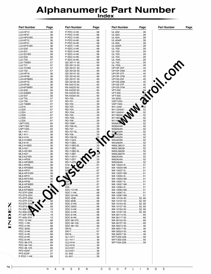
H A N S E N C O U P L I N G S76
IN
DE
X
Part Number Page Part Number Page Part Number Page Part Number Page
LL6-HP12 ............................. 36LL6-HP31 ............................. 36LL6-HP31BS ......................... 36LL6-KP12 .............................. 36LL6-KP31 .............................. 36LL6-KP31BS ......................... 36LL6-S30 ................................ 56LL6-S31 ................................ 56LL6-S31BS ........................... 56LL6-S32 ................................ 56LL6-T30 ................................ 57LL6-T30BS ........................... 57LL6-T31 ................................ 57LL6-T31BS ........................... 57LL6-T32 ................................ 57LL8-HP16 ............................. 36LL8-HP36 ............................. 36LL8-HP36BS ......................... 36LL8-KP16 .............................. 36LL8-KP36 .............................. 36LL8-KP36BS ......................... 36LL8-S36 ................................ 56LL8-S36BS ........................... 56LL8-S37 ................................ 56LL8-T35 ................................ 57LL8-T36 ................................ 57LL8-T36BS ........................... 57LLS16 ................................... 67LLS20 ................................... 67LLS24 ................................... 67LLS26 ................................... 67LLS30 ................................... 67LLS35 ................................... 67LNFT-200 .............................. 60LNFT-300 .............................. 60LNFT-500 .............................. 60ML1-H11 ............................... 36ML1-K11 ............................... 36ML2-H16 ............................... 36ML2-H16BS .......................... 36ML2-K16 ............................... 36ML2-K16BS .......................... 36ML3-H21 ............................... 36ML3-H21BS .......................... 36ML3-K21 ............................... 36ML3-K21BS .......................... 36ML4-HP26 ............................ 36ML4-HP26BS ........................ 36ML4-KP26 ............................. 36ML4-KP26BS ........................ 36ML6-HP31 ............................ 36ML6-HP31BS ........................ 36ML6-KP31 ............................. 36ML6-KP31BS ........................ 36ML8-HP36 ............................ 36ML8-HP36BS ........................ 36ML8-KP36 ............................. 36ML8-KP36BS ........................ 36P2-STP-25M ......................... 58P2-STS-25H ......................... 58P3-STP-25M ......................... 58P3-STP-37H ......................... 58P3-STP-37M ......................... 58P3-STS-37H ......................... 58P4-30P-25M ......................... 19P4-30S-25H .......................... 19P7-40P-37M ......................... 19P7-40S-37H .......................... 19PDC-12-HK ........................... 68PDC-1-HK ............................. 68PDC-2-HK ............................. 68PDC-3000 ............................. 68PDC-3-HK ............................. 68PDC-4-HK ............................. 68PDC-6-HK ............................. 68PDC-8-HK ............................. 68PDC-96-075 .......................... 69PDC-96-100 .......................... 69PDC-96-125 .......................... 69PP2-H25F ............................. 37PP2-K25F ............................. 37P-PDC-1-HK ......................... 68
P-PDC-2-HK ......................... 68P-PDC-3-HK ......................... 68P-PDC-4-HK ......................... 68P-PDC-6-HK ......................... 68P-PDC-8-HK ......................... 68P-SDC-1-HK ......................... 68P-SDC-2-HK ......................... 68P-SDC-3-HK ......................... 68P-SDC-4-HK ......................... 68P-SDC-6-HK ......................... 68P-SDC-8-HK ......................... 68QD 29111 00 ........................ 69QD 29112 00 ........................ 69QD 29121 00 ........................ 69QD 29122 00 ........................ 69QD 29141 00 ........................ 69QD 29142 00 ........................ 69QD 29151 00 ........................ 69QD 29152 00 ........................ 69RA 04210 00 ......................... 65RA 04220 00 ......................... 65RA 04230 00 ......................... 65RA 04240 00 ......................... 65RA 04250 00 ......................... 65RD-700 ................................. 29RD-701 ................................. 29RD-702 ................................. 29RD-703 ................................. 29RD-704 ................................. 29RD-704L ............................... 29RD-705 ................................. 29RD-705L ............................... 29RD-706 ................................. 29RD-706P ............................... 29RD-706-SL ............................ 29RD-707 ................................. 29RD-707-SL ............................ 29RD-708 ................................. 29RD-708-SL ............................ 29RD-7-0A3 .............................. 29RD-7-0B3 .............................. 29RD-7-0B3-SL ........................ 29RD-7-0B5 .............................. 29RD-7-0B5-SL ........................ 29RD-7-0B7 .............................. 29RD-7-0D11 ........................... 29RD-7-0D7 ............................. 29RD-7-0D9 ............................. 29S19 ....................................... 67S20 ....................................... 67S205 ..................................... 67S21 ....................................... 67S22 ....................................... 67S23 ....................................... 67S24 ....................................... 67S25 ....................................... 67S26 ....................................... 67SDC-12-HK ........................... 68SDC-1-HK ............................. 68SDC-20-HK ........................... 68SDC-4DB .............................. 68SDC-8DB .............................. 68SDC-2-HK ............................. 68SDC-3000 ............................. 68SDC-3-HK ............................. 68SDC-4-HK ............................. 68SDC-6-HK ............................. 68SDC-8-HK ............................. 68SDC-96-075 .......................... 69SDC-96-100 .......................... 69SDC-96-125 .......................... 69SN16 ..................................... 67SN17 ..................................... 67SN18 ..................................... 67UL1-H11 ............................... 36UL1-K11 ............................... 36UL2-H16 ............................... 36UL2-K16 ............................... 36UL3-H21 ............................... 36UL3-K21 ............................... 36UL-600 .................................. 28UL-601 .................................. 28
UL-602 .................................. 28UL-603 .................................. 28UL-604 .................................. 28UL-604R ............................... 28UL-605 .................................. 28UL-605R ............................... 28UL-700 .................................. 29UL-702 .................................. 29UL-703 .................................. 29UL-704 .................................. 29UL-704L ................................ 29UL-705 .................................. 29UL-705L ................................ 29UP10P-25F ........................... 45UP10P-25M .......................... 45UP10P-37F ........................... 45UP10P-37M .......................... 45UP10S-25F ........................... 45UP10S-25M .......................... 45UP10S-37F ........................... 45UP10S-37M .......................... 45VFT-200 ................................ 59VFT-300 ................................ 59VFT-500 ................................ 59VS-3000 ................................ 59VSFT-200 .............................. 59VSFT-500 .............................. 59W11J340 .............................. 52W11J54041 .......................... 52W11J64041 .......................... 52W11M340 ............................. 52W11M540 ............................. 52W11M640 ............................. 52W28A34N ............................. 52W28A54N ............................. 52W28A64N ............................. 52W54A32N ............................. 52W54A33N ............................. 52W54A52N ............................. 52W54A53N ............................. 52W54A62N ............................. 52W60L38012 .......................... 52W60L38038 .......................... 52W60L58058 .......................... 52W60L68078 .......................... 52W62A34N ............................. 52W62A54N ............................. 52W62A64N ............................. 52WA 10034 I0 ......................... 51WA 10034 M0 ....................... 51WA 10037 I0 ......................... 51WA 10037 M0 ....................... 51WA 10054 I0 ......................... 51WA 10054 M0 ....................... 51WA 10057 I0 ......................... 51WA 10057 M0 ....................... 51WA 10064 I0 ......................... 51WA 10064 M0 ....................... 51WA 10067 I0 ......................... 51WA 10067 M0 ....................... 51WA 10134 00 .................. 52, 69WA 10137 00 .................. 52, 69WA 10154 00 .................. 52, 69WA 10157 00 .................. 52, 69WA 10164 00 .................. 52, 69WA 10167 00 .................. 52, 69WA 56114 00 ........................ 69WA 56117 00 ........................ 69WA 56124 00 ........................ 69WA 56127 00 ........................ 69WA 56514 00 ........................ 46WA 56517 00 ........................ 46WA 56524 00 ........................ 46WA 56527 00 ........................ 46WFT-200-228 ........................ 59WFT-300-228 ........................ 59WFT-500-228 ........................ 59
Alphanumeric Part Number
Index
Air-O
il Sy
stems,
Inc.
www.a
iroil.co
m

H A N S E N C O U P L I N G S77
Notes
Air-O
il Sy
stems,
Inc.
www.a
iroil.co
m

H A N S E N C O U P L I N G S78
Notes
Air-O
il Sy
stems,
Inc.
www.a
iroil.co
m

H A N S E N C O U P L I N G S
WarrantyEvery effort has been made to have all photographs and drawings accurately represent the products as they actually were at the time this catalog was printed. Obviously, however, so that we may effectively continue to meet the requirements of our users, changes in some items may have been made during the life of this catalog—which, on occasion, may be made without notice.
All Tuthill Coupling Group products are guaranteed, for a period of 90 days from the date of shipment to a customer, to be free of defects in material and workmanship. Any claimed defect must be reported to the Tuthill Coupling Group in writing within the warranty period. This warranty is limited to replacing or repairing, at the Company’s option, f.o.b. the Company’s factory, any part which upon Company inspection is found to be defective. Components purchased by the Company from others are warranted only to the extent of the guarantee or warranty, if any, made to the Company.
THE ABOVE WARRANTY COMPRISES THE COMPANY’S SOLE AND ENTIRE WARRANTY OBLIGATION AND LIABILITY IN CONNECTION WITH TUTHILL COUPLING GROUP HANSEN COUPLINGS. ALL OTHER WARRANTIES, EXPRESS OR IMPLIED, INCLUDING, WITHOUT LIMITATION, WARRANTIES OR MERCHANTABILITY AND FITNESS FOR A PARTICULAR PURPOSE, ARE EXPRESSLY EXCLUDED. THE COMPANY IN NO EVENT SHALL BE LIABLE FOR INDIRECT OR CONSEQUENTIAL DAMAGES ARISING OUT OF THE SALE OR USE OF HANSEN COUPLINGS.
About Industry Interchanges...It is possible to connect two different manufacturers’ parts together so that they will effect a seal and work properly in a fluid system. Tuthill Coupling Group cannot guarantee the quality, workmanship, dimensions, or toler-ances of the other manufacturers’ parts, even though they might be interchangeable. Therefore, whenever mixing parts, the final assemblsevere personal injury or death.
WARRANTY
Technical and Warranty Information
•
Couplings do wear out. In order to avoid severe bodily injury or death, couplings must be routinely checked for condition and replaced if necessary.
Over-pressurization could result in a sudden failure of the coupling causing severe bodily injury or death. Be sure to select the proper coupling for your application and use it only within the specified service pressure range.
Pressure Ratings**Since application conditions vary so widely, the pressures listed are intended as a guide only and not a guarantee of performance. Pressure peaks and extreme surge flows may cause a coupling to become inoperative.
SERVICE PRESSUREService pressure is the “rated pressure” as defined by ANSI/B93.2-1971, as “the qualified operating pressures which are recommended for a component or a system by the manufacturer.”
**NOTE!Pressure ratings listed were determined by testing threaded sockets and plugs. Sockets and plugs with hose stem and hose clamp end connections are designed and recommended for use with shop air line pressure only (150 psig maximum) when used with the appropriate style hose.
PROUD MEMBERS OF:
Air-O
il Sy
stems,
Inc.
www.a
iroil.co
m

1000 West Bagley Road, P.O. Box 805Berea, Ohio USA 44017-0805Tel 440 826-1115 Fax 440 826-1105www.tuthill.com
Q U I C K C O U P L I N GR E F E R E N C E G U I D E
Catalog No.00-1 ©2006 Tuthill Corporation Printed in the U.S.A. 11/06
Air-O
il Sy
stems,
Inc.
www.a
iroil.co
m


