Meggitt (North Hollywood), Inc. Proprietary Information
The information contained in this document is disclosed in confidence. It is the property of Meggitt (North Hollywood), Inc. and shall not be used, disclosed to others, or reproduced in whole or in part without the express written consent of Meggitt (North Hollywood), Inc. If consent is given, this notice shall appear in any such reproduction. These commodities, technology, or software were exported from the United States in accordance with the export administration regulations. Diversion contrary to U.S. law is prohibited.
SENSITIVE BUT UNCLASSIFIED-EXPORT CONTROLLED-EAR RESTRICTED. These commodities, technology or software are exported from the United States of America in accordance with the Export Administration Regulations. ECCN EAR99. Diversion contrary to U.S. law is prohibited.
Air Set Pressure Control Hydrant Valve – F368/F372 Series
USE OR DISCLOSURE OF DATA ON THIS PAGE IS SUBJECT TO THE RESTRICTIONS ON THE TITLE PAGE OF THIS DOCUMENT
15 Jan 2014 Revision 2.0 i
REVISION RECORD
Keep this record in the front of the manual. When you get the revisions, put the revised pages in the manual. Write the revision number, date issued and your initials on this page.
Air Set Pressure Control Hydrant Valve – F368/F372 Series
USE OR DISCLOSURE OF DATA ON THIS PAGE IS SUBJECT TO THE RESTRICTIONS ON THE TITLE PAGE OF THIS DOCUMENT
15 Jan 2014 Revision 5.0 A
IMPORTANT SAFETY INSTRUCTIONS
SAVE THESE INSTRUCTIONS!
This manual contains important instructions that should be followed during installation and maintenance of the Air Set Pressure Control Hydrant Valve. The following are general safety precautions that are not related to specific procedures and therefore do not appear elsewhere in this publication. These are recommended precautions that personnel must understand and apply during maintenance.
The Valve is a mechanical device, and can be dangerous if not correctly operated or maintained.
Safety Alert Symbols
Safety alert symbols are used in this manual to identify potential or immediate personal injury hazards. The safety alert symbol words are explained below:
- indicates an imminently hazardous situation which, if not avoided, will result in injury or serious injury.
- indicates a potentially hazardous situation which, if not avoided, could result in injury or serious injury.
- indicates a potentially hazardous situation which, if not avoided, may result in minor or moderate injury.
- used without the safety alert symbol indicates a potentially hazardous situation which, if not avoided, may result in property damage.
WEAR PROTECTIVE CLOTHING
Wear protective clothing (gloves, apron, etc.) approved for the materials and tools being used.
USE APPROVED SAFETY EQUIPMENT
Use only approved equipment and make sure firefighting equipment is readily available.
Air Set Pressure Control Hydrant Valve – F368/F372 Series
USE OR DISCLOSURE OF DATA ON THIS PAGE IS SUBJECT TO THE RESTRICTIONS ON THE TITLE PAGE OF THIS DOCUMENT
15 Jan 2014 Revision 2.0 1
INTRODUCTION
1. General
The information and procedures contained in this manual have been prepared to assist qualified repair personnel in off-aircraft maintenance of the Air Set Pressure Control Hydrant Valve. The instructions provide information necessary to perform maintenance functions. The Valve is manufactured by Meggitt (North Hollywood), Inc., 12838 Saticoy Street, North Hollywood, California 91605.
2. Scope
The instructions contained in this manual do not claim to cover all details or variations in equipment. They do not provide for every problem that could occur during installation, operation, or maintenance. If further information is required, contact Meggitt (North Hollywood), Inc., Product Support Department.
3. Standard Shop Practices
Use approved procedures and safety precautions to prevent damage to the equipment and injury to personnel.
4. Weights and Measurements
Weights and measurements in this manual are expressed in both English (U.S. customary) and Metric (SI) units.
5. Revision Service
This manual will be revised, as necessary, to reflect current information.
Air Set Pressure Control Hydrant Valve – F368/F372 Series
USE OR DISCLOSURE OF DATA ON THIS PAGE IS SUBJECT TO THE RESTRICTIONS ON THE TITLE PAGE OF THIS DOCUMENT
15 Jan 2014 Revision 2.0 2
DESCRIPTION AND OPERATION
1. Description
The Air Set Pressure Control Hydrant Valve (valve) provides the means of controlling flow in aircraft refueling operations. The valve inlet is connected to the riser flange of the underground fuel piping. The outlet adapter mates with a hydrant coupler or coupler/regulator attached to a hose supplying or receiving fuel.
See Figure 1 for the Functional Schematic - Basic Principle of operation of the F368 and F372 Valves.
2. Operation
A. Pressure Control
Air reference pressure is required in this mode. The reference pressure is somewhat higher than the desired control pressure. This difference is called as “bias”.
B. Deadman Control
In this mode, the valve closes if the reference pressure is vented.
C. Aircraft Valve Response
In this mode, as downstream pressure increases (caused by aircraft valve closure), the pressure causes the hydrant valve to close, preventing excessive surge pressure build-up.
D. Excess Flow Control
This mode provides shut-off control if the flow rate exceeds a preset value. This feature is available as a modification, either in an adjustable single range, or as a two-position setting.
Air Set Pressure Control Hydrant Valve – F368/F372 Series
USE OR DISCLOSURE OF DATA ON THIS PAGE IS SUBJECT TO THE RESTRICTIONS ON THE TITLE PAGE OF THIS DOCUMENT
15 Jan 2014 Revision 2.0 4
3. Leading Particulars
For the leading particulars refer to Table 1.
Table 1. Leading Particulars
Service Fluid .................................................................................................................. Automotive and Aviation Fuels
Control ........................................................................................................................... 15 to 75 psi (1 to 5.2 bar)
Mod A ........................................................................................................................................... 16 psi (1.1 bar)
Mod K ........................................................................................................................................... 10 psi (0.7 bar)
Pressure Drop:
With F203/F230/F240 Hydrant Coupler ................................................. 14 psi at 1000 gpm (1 bar at 3785 lpm)
With F205/F211 Hydrant Coupler .......................................................... 17 psi at 600 gpm (1.2 bar at 2271 lpm)
Adjustment Range ............................................................................................................. 10 to 50 seconds
Closing .................................................................................................................................................. 0.3 second
Air Set Pressure Control Hydrant Valve – F368/F372 Series
USE OR DISCLOSURE OF DATA ON THIS PAGE IS SUBJECT TO THE RESTRICTIONS ON THE TITLE PAGE OF THIS DOCUMENT
15 Jan 2014 Revision 2.0 5
4. Model Variations
Refer to Table 2 for the available F368 valve variations. Refer to Table 3 for the available F372 valve variations. Refer to the ILLUSTRATED PARTS LIST section for additional details.
Table 2. F368 Model Variations
MOD LETTER DESCRIPTION
(Basic) 4 x 4 inch, ductile iron body, cover and servo housing, 25 psi bias spring, product selection (set to Position 4), outlet to mate F203 and F230 couplers, air fuel sense plug to mate an F571 socket, excess flow valve (set to 670 gpm)
A Changes bias spring to 16 psi
C Adds dual selection excess flow valve (for both high and low flow rates) (must be used with F571 socket)
E Removes excess flow valve
K Changes bias spring to 10 psi
Table 3. F372 Model Variations
MOD LETTER DESCRIPTION
(Basic) 4 x 2.5 inch, ductile iron body, adapter and servo housing, 25 psi bias spring, product selection ring (set to Position 4), outlet to mate F200, F204, F205 and F211 couplers, air fuel sense plug to mate an F571 socket
A Changes bias spring to 16 psi
C Adds dual selection excess flow valve (for both high and low flow rates) (must be used with F571 socket)
Air Set Pressure Control Hydrant Valve – F368/F372 Series
USE OR DISCLOSURE OF DATA ON THIS PAGE IS SUBJECT TO THE RESTRICTIONS ON THE TITLE PAGE OF THIS DOCUMENT
15 Jan 2014 Revision 2.0 6
FAULT ISOLATION
1. General
This section contains fault isolation procedures for the valve. Operate the valve in accordance with the DESCRIPTION AND OPERATION section; if the valve fails to operate correctly refer to Table 4. Table 4 identifies the Fault, Probable Cause and Corrective Action.
Table 4. Fault Isolation
FAULT PROBABLE CAUSE CORRECTIVE ACTION
Valve will not open Reference pressure is low Set reference pressure to 25 psi higher than control pressure. For Mod A, 16 psi higher than control pressure. For Mod K, 10 psi higher than control pressure.
Opening time adjustment screw too far in
Back the screw out 1/2-turn and check operation.
Servo valve sticking Actuate the deadman control several times and check operation.
Valve operation is unstable Air trapped in fuel sense line Completely bleed trapped air from the servo valve and the fuel sense line.
Opening time is too fast Adjust the opening time screw all the way in and then back it out 1/8-turn. If necessary, adjust the screw 1/8-turn further out, and repeat until operation stabilizes.
Servo valve or main piston sticking Actuate the deadman control several times and check operation.
Air Set Pressure Control Hydrant Valve – F368/F372 Series
USE OR DISCLOSURE OF DATA ON THIS PAGE IS SUBJECT TO THE RESTRICTIONS ON THE TITLE PAGE OF THIS DOCUMENT
15 Jan 2014 Revision 2.0 7
Table 4. Fault Isolation (continued)
FAULT PROBABLE CAUSE CORRECTIVE ACTION
Valve operation is unstable (continued)
Reference pressure is too low Set reference pressure to 25 psi higher than control pressure. For Mod A, 16 psi higher than control pressure. For Mod K, 10 psi higher than control pressure.
Sense line restricted Make sure the sense line is 3/8-inch inside diameter.
Sense line (hose) too soft Make sure the hose is sufficiently strong to prevent expansion and contraction.
Valve will not fully close Servo valve or main piston sticking Actuate the deadman control several times and recheck operation.
Air Set Pressure Control Hydrant Valve – F368/F372 Series
USE OR DISCLOSURE OF DATA ON THIS PAGE IS SUBJECT TO THE RESTRICTIONS ON THE TITLE PAGE OF THIS DOCUMENT
15 Jan 2014 Revision 2.0 8
CLEANING
1. Cleaning Materials
Refer to Table 5 for recommended cleaning materials. Equivalent items may be used.
Table 5. Recommended Cleaning Materials
DESCRIPTION SPECIFICATION SOURCE
Alcohol, Isopropyl ASTM D770 Commercially available
Bags, Plastic - Commercially available
Brush, Bristle, Stiff, Non-metallic - Commercially available
Pick, Teflon® - Commercially available
Solvent, Dry Cleaning P-D-680, Type 2 Commercially available
Tissues, Lint-free - Commercially available
2. Cleaning Procedures
DRY CLEANING SOLVENT AND ISOPROPYL ALCOHOL ARE HARZARDOUS MATERIALS. BEFORE USE, READ AND FOLLOW THE MATERIAL SAFETY DATA SHEET (MSDS) INSTRUCTIONS FOR CORRECT HANDLING. FAILURE TO OBEY THIS WARNING MAY RESULT IN PERSONAL INJURY, LONG TERM HEALTH HAZARDS OR DEATH.
A. Clean all of the metal parts by washing them thoroughly in dry cleaning solvent. Remove any stubborn deposits by scrubbing them with a non-metallic stiff bristle brush. Use a Teflon® pick to remove obstructions from the ports, the grooves, and the flow passages.
B. Clean all of the non-metallic parts by wiping them with clean lint-free tissues slightly moistened with isopropyl alcohol.
NOTE: All parts must be free of corrosion, dirt, grease, oil or any other foreign matter.
Air Set Pressure Control Hydrant Valve – F368/F372 Series
USE OR DISCLOSURE OF DATA ON THIS PAGE IS SUBJECT TO THE RESTRICTIONS ON THE TITLE PAGE OF THIS DOCUMENT
15 Jan 2014 Revision 2.0 10
CHECK/INSPECTION
1. General
Under strong light and magnification, look at all parts in accordance with the general criteria specified in Table 6.
2. Component Checks (Refer to Table 6)
Table 6. Component Checks
DESCRIPTION INSPECTION CRITERIA
General Look at the parts for; nicks, cracks, cuts, burrs, corrosion, breaks, scoring, dents, thread damage, serration damage, or other damage.
Make sure the ports, passages, recesses, and grooves are clean and are not blocked.
Make sure all sealing and seating surfaces are free from damage or corrosion.
If any cracks are suspected, perform a magnetic particle inspection (for ferrous metal parts) in accordance with MIL-I-6868 or a penetrant examination (non-ferrous metal parts) in accordance with MIL-I-6866.
NOTE: Burrs, nicks, and scratches are defined as material raised above normal surface, which if not removed would prevent complete and proper mating of parts and sealing surfaces. Where nicks or scratches allow bare metal to show through a protective finish, note defect and assign part for repair. Dents or damage must not impair finish or functional operation of any part.
Air Set Pressure Control Hydrant Valve – F368/F372 Series
USE OR DISCLOSURE OF DATA ON THIS PAGE IS SUBJECT TO THE RESTRICTIONS ON THE TITLE PAGE OF THIS DOCUMENT
15 Jan 2014 Revision 2.0 11
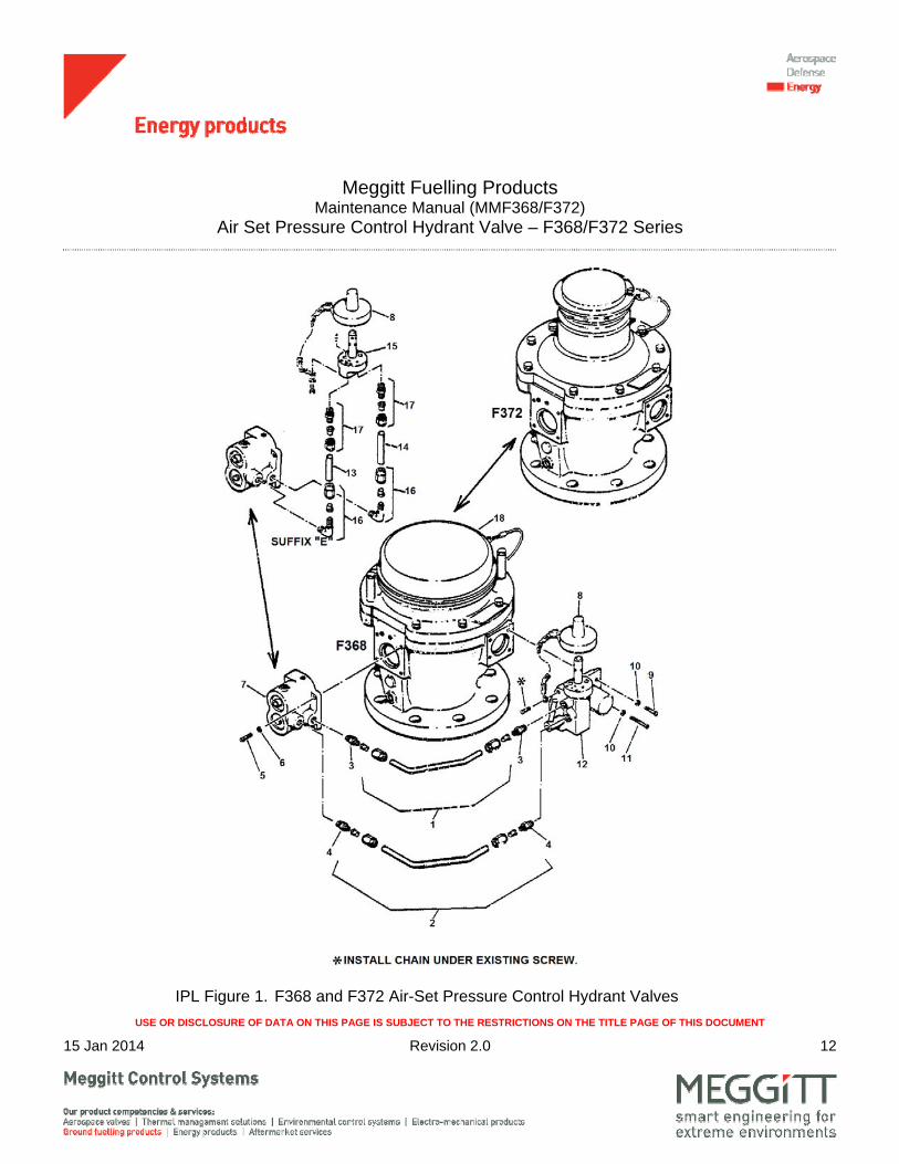
ILLUSTRATED PARTS LIST
1. General
This section lists, describes, and illustrates all detail parts required for maintenance support of the Air Set Pressure Control Hydrant Valve.
2. Scope of Information
The parts list is arranged in the general order of disassembly. The listing is indented to show the relationship between each part and its next higher assembly. Item numbers used in the parts list are keyed to the corresponding numbers of the accompanying illustration.
A. MODIFICATION CODE
The modification code indicates the parts usage with respect to the end item. When the MOD column is blank, the part usage is applicable to all versions unless otherwise specified in the DESCRIPTION column.
B. How to Identify a Part
When the part number is known: Refer to the parts list for the item number, description, modification codes, and quantity. Refer to the illustration to make sure the physical appearance and location of the part.
When the part number is not known: Look at the illustrations to identify the part by physical appearance and location. Refer to the accompanying parts list to get the part number, nomenclature, modification codes, quantity, etc.
7 4631050 . SERVO ASSY ................................................................ (SEE MM4631050 FOR DETAILS)
BASIC, C 1
4631050A . SERVO ASSY ................................................................ (SEE MM4631050 FOR DETAILS)
A 1
4631050E . SERVO ASSY ................................................................ (SEE MM4631050 FOR DETAILS)
K 1
8 2642566 . CAP ASSY ...................................................................... 1
9 CNAS1352C4-10 . SCREW, SOCKET HEAD CAP ..................................... BASIC, A, C 2
10 CMS35338-139 . WASHER, LOCK ........................................................... BASIC, A, C 4
11 CNAS1352C4-24 . SCREW, SOCKET HEAD CAP ..................................... BASIC, A, C 2 12 F576 . SERVO, EXCESS FLOW ...............................................
(SEE MMF576 FOR DETAILS) BASIC, A 1
F576B . SERVO, EXCESS FLOW ............................................... (SEE MMF576 FOR DETAILS)
C 1
13 2651846-1 . TUBE .............................................................................. E 1 14 2651846-2 . TUBE .............................................................................. E 1 15 F554A . PLUG .............................................................................. E 1 16 4-4CBZSS . ELBOW ASSY ................................................................ E 2 17 4-4FBZSS . CONNECTOR ASSY ...................................................... E 2 18 . BODY AND PISTON ASSY ............................................


![[XLS] PUMPS BOQ.xls · Web viewProviding and fixing in position horizontal Multistage Fire Hydrant Pump with constant pressure water, supply of average discharge pressure, comprising](https://static.documents.pub/doc/80x56/5a9e74737f8b9a6c178b62b8/xls-pumps-boqxlsweb-viewproviding-and-fixing-in-position-horizontal-multistage.jpg)
