50
Grant Aerona Air Source Heat Pump Air to Water Heat Pump Range Installation & User Instructions Part No. DOC.87 Rev.00 January 2010 Tested to BS EN 14511

Grant Aerona Air Source Heat PumpAir to Water Heat Pump Range
Installation & User Instructions
Part No. DOC.87 Rev.00 January 2010
Tested to BS EN 14511

i
ST
OP
STOP!
� Has a heat loss calculation been carried out? kW
� Is this system designed for Mono or Bivalent
� If Mono, total heating capacity? kW
� If Bivalent, what is the load capacity of Heat Pump? kW
� If Bivalent, what is/are additional heat source(s)?
i) kW
ii) kW
iii) kW
� Type of system design?
i) S-plan
ii) Y-plan
iii) Other
� Will a buffer be used? Yes/No
� If yes, what is the capacity of Buffer? litres
� Has cavity wall insulation been installed? Yes/No
� Has loft insulation of 270mm been installed? Yes/No
� Have all system pipes been lagged correctly? Yes/No
� Are the existing controls being upgraded? Yes/No
Before continuing with the installation of your new Aerona Heat pump, please spenda few minutes confirming the suitability of the Heat Pump to your system. Failure todo so may result in poor performance and wasted time.
If any of the above questions cannot be answered accurately, please do NOTproceed with the installation. While any errors made now may be able to becompensated for after the installation is completed, you will incur unnecessarydelays and additional costs.

Leg
isla
tio
n
ii
All work that is required regarding the refrigerant circuit must be carried out by an F-gas registered (or equivalent) refrigeration Engineer. On no account shouldmaintenance or repair be carried out on the refrigerant circuit by unqualifiedpersonnel.
LEGISLATION
The installation of the Grant Aerona Heat Pump requires a power supply cable fromthe customer’s consumer unit to an external isolation switch and from this switch tothe heat pump. It will require a final connection to an individual MCB or RHBO withinthe existing consumer unit or from a newly installed consumer unit.
This work MUST be carried out by a qualified electrician or by a Part-P competentinstaller who has passed an examination proving their competency in these works.
Failure to follow this legislation will invalidate all warranties.
Please seek advice from a competent person before commencing any electricalwork.
Legislation
Information regarding the refrigerant used in this Heat Pump. R407cR407C is a mixture of three refrigerants, each of which boil at different temperatures. R407C has a range or glide of approximately5ºC. The lubricating oils used in this heat pump are known as Polyolester or POE oils. They are considered to be superior oils, lessliable to breakdown however they are more hygroscopic – they must therefore be kept from contact with air as far as is practical.
Information regarding the charging / recharging of the unit.Always add R407C as a liquid to ensure that the correct mix is added.
Charge the heat pump with the correct weight of refrigerant. See data plate for this information.
Never ‘top-up’ refrigerant. Always recover the remaining refrigerant first for recycling.
Information regarding a refrigerant leak or if the circuit is opened accidentally.Recover the remaining refrigerant as quickly as possible for recycling.
Avoid entry of air into the heat pump as much as possible.
Replace or install a drier if necessary.

iii
Co
nten
ts
ContentsStop! i
Legislation ii
Contents iii
1 Introduction 11.1 General Information 1
1.2 Warranty 1
1.3 Important Advice 1
1.4 Immersion Heater 1
2 Specifications and Controls 22.1 Specifications 2
2.2 Dimensions 2
2.3 Main Components 3
2.4 Heat Pump Curves 4
2.5 Pump Curves 5
2.6 Operating Sequences 5
2.7 Controls 6
3 Siting the Heat Pump 73.1 Position 7
3.2 Orientation 8
4 Hydraulic Diagrams 94.1 S-Plan Type - Monovalent 9
4.2 Extended S-Plan Type - Monovalent 9
4.3 S-Plan Type - Bivalent 10
4.4 Extended S-Plan Type - Bivalent 11
4.5 Buffer Tanks 12
4.6 S-Plan with Buffer - Monovalent 12
4.7 Extended S-Plan with Buffer - Monovalent 13
5 System Design Criteria 14
6 Calculating Radiator Sizes 15
7 Sealed Systems 16
8 Electrical 178.1 General 17
8.2 Basic Circuits – Making the Connection 17
8.3 Controller 19
8.4 Mains Supply Cable 19
8.5 Heat Pump Wiring Diagram 20
8.6 System Control Wiring Diagrams 22
8.7 Wiring Diagrams 23
8.8 Bivalent Systems 25
8.9 Extending the Electrics 25
9 Domestic Hot Water 269.1 Temperature Control 26
9.2 Heat Pump Cylinders 26
9.3 Temperature Boost 26
10 Filling the System 2810.1 Filling and Venting - Sealed Systems 28
10.2 Flushing and Corrosion Protection 28
10.3 Antifreeze 28
11 Commissioning 2911.1 Switching on First Time 29
11.2 Setting the ATC Controller 30
11.3 Setting the BTC Controller 32
11.4 Record of ATC and BTC Settings 34
12 Servicing & Maintenance 3512.1 General 35
12.2 Air Inlet and Outlet 35
12.3 Condensate Disposal 35
12.4 Heating System Connections 35
12.5 Heat Pump Controls 35
12.6 Refrigerant 35
13 Fault Finding 36
14 Spare Parts 40
15 Accessories 4115.1 Sealed System Kits 41
15.2 Immersion Heater Kits 41
16 Glossary Of Terms 42
17 Warranty 43

Intr
od
ucti
on
&
Gen
eral
Inf
orm
atio
n
1
1.1 General InformationThe Grant Aerona Heat Pump is a lowwater content – low temperature heatsource, designed to be highly efficientwhen installed and used in line withthese installation and user instructions.
It is important that these installationinstructions are understood andfollowed to ensure reliable operation inall weather conditions. Failure to do sowill result in erratic temperature swings,poor efficiency and an unhappycustomer.
It is not within the scope of this manualto design the heating system or provideany advice regarding the layout of thesystem or any of the controls requiredfor any individual heating system.
These instructions do not replace theinstallation or users manuals for anyadditional components used in thedesign of your system e.g. cylinders,motorised valves, programmers, solarthermal devices, buffers, etc.
Grant Engineering UK Ltd offer a designservice for an additional fee – pleasecontact [email protected] for moreinformation or visit our website atwww.grantuk.com Note: this serviceis subject to the terms and conditions inforce at the time of the design.
These instructions must be left with thehouseholder for their reference.
1.2 WarrantyThis appliance is guaranteed for twoyears, covering parts and labour. Whenmaking a claim against this warranty,the following information must beprovided at the initial point of contact.
• Appliance model number
• Appliance Serial number
• Date of Installation
• Date of Commissioning (if different)
• Evidence of Heat Loss calculation
• Description of fault together with anyrelevant fault codes
Please ensure that the caller ison site to assist us in providinga fast response.
The warranty will begin only when acompleted registration card is returnedto Grant, or when the registration iscompleted online at www.grantuk.com.Failure to complete the registration atthe time of installation will result in thewarranty being suspended. This doesnot affect the consumer’s statutoryrights.
If a Grant Engineer is required to visitthe site and no fault is found with theheat pump, a charge will be made forthis visit. The original caller will beresponsible for this charge.
Refer to Section 17 for full details of theGrant Heat Pump warranty.
1.3 Important Advice1. It is essential that the full layout of
the system is understood before theinstallation of any component isundertaken. If you are in any doubt,please stop and seek advice from aqualified heating engineer or fromGrant Engineering UK Ltd. Pleasenote that Grant Engineering will notbe able to offer specific adviceabout your system unless wedesigned it. In this case, we willalways refer you to seek the adviceof a qualified system designer.
2. The Heat Pump must be installedand commissioned in accordancewith these installation instructions.Deviations of any kind will invalidatethe warranty and may cause anunsafe situation to occur. Pleaseseek advice from Grant EngineeringUK Ltd if any of these installationinstructions cannot be followed forwhatever reason.
3. The heat pump contains highpressures and high temperaturesduring normal working conditions.Care must be taken whenaccessing the internal workings ofthe heat pump.
4. The heat pump contains anelectrically driven fan which rotatesat high speed. Disconnect the heatpump from the electrical supplybefore removing the top cover.
1.4 Immersion HeaterAll Grant Aerona Heat pumps aresupplied with a factory fitted 3kWimmersion element. This is designed tooperate at low ambient air temperaturesto increase the output of the unit tomeet the design heat load. Refer toSection 11 of these instructions fordetails of the automatic operation of theimmersion element.
If required, all Grant Aerona Heatpumps are available with a 6kW back-up immersion element (in place of thestandard 3kW unit).
This is a factory fitted option ONLY andmust be specified when ordering theheat pump.
For the starting and running current,along with the required MCB rating/typefor units with either the 3kW or 6kWimmersion elements refer to Section 8(page 21) of these instructions.
1 Introduction & General Information
IMPORTANT
Grant Aerona heat pumps should be stored andtransported in an upright position. If not, the heatpump MUST be positioned in an upright position forat least 4 hours before being operated.

2
Sp
ecifi
cati
ons
and
Co
ntro
ls
2 Specifications and Controls2.1 Specifications
2.2 Dimensions
Model HPAW65 HPAW85 HPAW110 HPAW130 HPAW155
Heating Capacity kW 6.78 8.73 11.32 12.58 15.5
Input Power kW 1.62 2.20 2.61 2.59 2.77
Running Current A 7.36 10.0 11.7 11.8 12.6
Power supply V 230 230 230 230 230
Phase Single Single Single Single Single
Frequency Hz 50 50 50 50 50
Mechanical Protection IP X4 IP X4 IP X4 IP X4 IP X4
Refrigerant R407c R407c R407c R407c R407c
Mass of R407c g 1300 1750 1900 2200 2300
Built In Immersion kW 3 3 3 3 3
Circulating Pump m head 6 6 6 6 15
Flow Rate litres/sec 0.311 0.422 0.54 0.61 0.724
Sound Level at 1m dB(A) 52 52 52 52 58
Water Connections BSPF 3/4" 3/4" 1" 1" 1"
COP @ Air 7˚C/Water 35˚C 4.1 3.9 4.3 4.8 5.8
Weight (empty) kg 94 115 138 152 172
Weight (full) kg 111 134 156 170 191
1120 430 165
Electrical inletglands
5050
900
Front View Rear View
90
90
920
250
125
485
307
400 70
1120 430 200
110
Electrical inletglands
Flow
Return
Flow
Return
5050
900
Front View Rear View
90
90
1165
250
8569
039
5
400 265
Figure 2-1: HPAW65 model
Figure 2-2: HPAW85, HPAW110 & HPAW130 models
Sp
ecifi
cati
ons
and
Co
ntro
ls
3
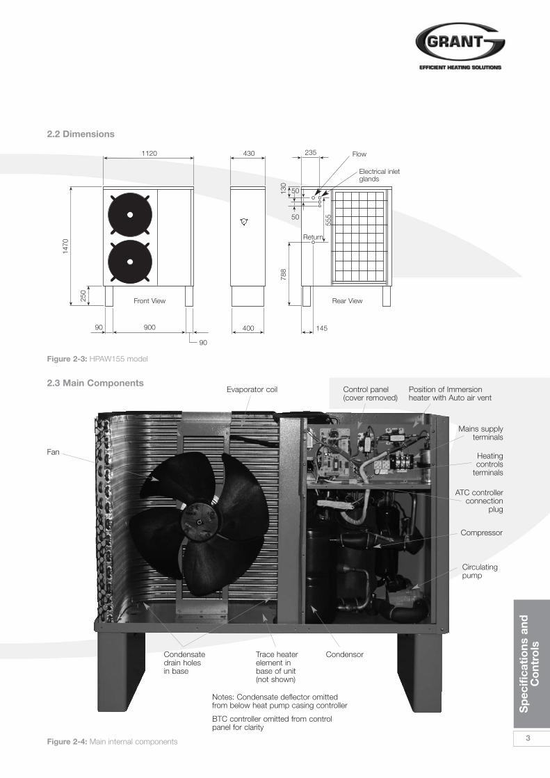
2.2 Dimensions
1120 430 235
Electrical inletglands
Flow
Return
900
Front View
Fan
Rear View
90
90
1470
250
130
50
50
555
788
400 145
2.3 Main Components
Figure 2-3: HPAW155 model
Figure 2-4: Main internal components
Evaporator coil Control panel(cover removed)
Position of Immersionheater with Auto air vent
Condensatedrain holesin base
Trace heaterelement inbase of unit(not shown)
Notes: Condensate deflector omittedfrom below heat pump casing controller
BTC controller omitted from controlpanel for clarity
Condensor
Circulatingpump
Compressor
ATC controllerconnection
plug
Mains supplyterminals
Heatingcontrols
terminals

4
Sp
ecifi
cati
ons
and
Co
ntro
ls
2 Specifications and Controls2.4 Heat Pump Curves
Water Flow Temperature
35˚C
50˚C
Air Temperature in ˚C
Hea
t P
ump
Out
put
in k
W
-10 0 10 20 30 40
16
14
12
10
8
6
4
2
0
COP4.1
COP4.8
COP3.9
COP4.3
COP5.8
Water Flow Temperature
35˚C
50˚C
Air Temperature in ˚CH
eat
Pum
p O
utp
ut in
kW
-10 0 10 20 30 40
16
14
12
10
8
6
4
2
0
16
14
12
10
8
6
4
2
0
Water Flow Temperature
35˚C
50˚C
Air Temperature in ˚C
Hea
t P
ump
Out
put
in k
W
-10 0 10 20 30 40
16
14
12
10
8
6
4
2
0
Water Flow Temperature
35˚C
50˚C
Air Temperature in ˚C
Hea
t P
ump
Out
put
in k
W
-10 0 10 20 30 40
Water Flow Temperature
35˚C
50˚C
Air Temperature in ˚C
Hea
t P
ump
Out
put
in k
W
-10 0 10 20 30 40
16
14
12
10
8
6
4
2
0
All Grant Aerona heat pumps havebeen independently third partytested to BS EN 14511. The COPdata given above is based on 7˚Cambient air and 35˚C watertemperature. This information shouldbe used as guidance only and not toestimate the COP at othertemperatures.
! NOTE
Figure 2-5: Grant HPAW65 Figure 2-8: Grant HPAW130
Figure 2-6: Grant HPAW85
Figure 2-7: Grant HPAW110
Figure 2-9: Grant HPAW155

Sp
ecifi
cati
ons
and
Co
ntro
ls
5
2.5 Pump Curves
Pum
p H
ead
(met
res)
Pum
p H
ead
(met
res)
6
5
4
3
2
1
0
Wilo-Classic Star
0 0.5 1 1.5 2 3)Flow (m3/h)
Flow (m3/h)
Star-RS 15/6. 25/6
2.6 Heat Pump Operating Sequences
Pump OFF
ON
ON
ON
ON
OFF
OFF
OFF
OFF
0(on)
0(off)
25 30 25 30
Fan
Comp
Demand
Fan
Pump
OFF OFF
OFF
OFF
ON
ON ON
ON ON
OFF
OFFON
ON
ON
Comp
4-wayvalve
Defrostsignal
0(on)
10 60 off BTCPump delay
time
Time secs Time secs
15.5kW Pump Curve
15
10
5
00 1.2 2.4 3.6 4.8
PUN-200E
Figure 2-10: Pump curve for HPAW65, HPAW85, HPAW110 & HPAW130
Figure 2-12: Normal operating sequence Figure 2-13: Defrost cycle
Figure 2-11: Pump curve for HPAW155

6
Sp
ecifi
cati
ons
and
Co
ntro
ls
All Grant Aerona Heat Pumps aresupplied with 2 controllers. 1 x heatpump controller (ATC) and 1 xtemperature controller (BTC).
The ATC is positioned inside thehouse/building and is normally used inan automatic condition. There are a fewparameters that can be adjustedincluding time and maximum watertemperature. The details of thesesettings can be found in Section 11 ofthis manual.
The BTC is a split temperaturecontroller located inside the heat pump.For many installations, the DHWtemperature and the CH temperaturewill be different. The BTC allows for 2different design temperatures to beentered, maximising the efficiency of theGrant Aerona heat pump. The details ofthese settings can be found in Section11 of this manual.
All other controls (programmers,motorised valves, thermostats, etc) arenot supplied but their use is covered inSections 4 and 8 of this installationmanual.
2.7 Controls
2 Specifications and Controls
Figure 2-11: ATC Controller Figure 2-12: BTC Controller

Sit
ing
the
Hea
t P
ump
7
3 Siting the Heat Pump
1. BaseThe heat pump should be installedon a flat trowelled finished concretebase 150mm thick. This baseshould extend at least 100mmbeyond the unit on three sides. Theedge of the concrete base on theside closest to the building shouldbe flush with that face of the heatpump. Refer to Figure 3-1.
To avoid bridging the DPC, leave agap of at least 300mm between theconcrete base and the wall of thehouse.
The Underside of the heat pump isfitted with a condensate deflectorthat directs the condensate to therear of the unit. To allow thiscondensate to safely drain away,there should be a shallow trench atleast 150mm wide, filled with stonechippings, along the rear edge ofthe concrete base. This trench canextend across the gap between theconcrete base and the house(minimum distance 300mm) but thechippings must be below thebuilding DPC level.
3.1 Position
300mm
Figure 3-1: Installation details
100mmmin
200mm min aboveground level
150mm minimum
Trench with chippings
Edge of baseflush with rear of
heat pump
Concrete base
DPC
IMPORTANT
It is essential that the condensate is able to drainaway and not allowed to run onto any adjacentpaths or driveways where, in winter, this will resultin icing and a potential hazard for anyone walkingnear the heat pump.
The top of the concrete base must be either level with,or above, the surrounding ground level. Always ensureat least 200mm vertical clearance between thesurrounding ground level and the underside of the heat pump to allow for adequate air movement. Refer to Figure 3-1 for details.
2. ClearancesThe Heat pump should have aminimum of 300mm from the rearof the unit to any wall and not haveany obstruction within 1000mmfrom the front or either side of theunit. Do not rest objects on top oragainst any part of the heat pumpunder any circumstances. Do notinsert objects into the fan guard.
3. Noise LevelAll heat pumps make a noise.Discuss the potential nuisancefactor with the end-user whenconsidering the final position of theheat pump. Take opening windowsand doors into account. It is notessential for the heat pump to bepositioned next to a wall of thehouse. Behind an out-building maybe more suitable so discuss theoptions with the end-user.
4. InsulationRemember, all pipe work,irrespective of length, must be wellinsulated to prevent heat loss. Theuse of barrier plastic pipe togetherwith double thick insulation isstrongly recommended, particularlywhen considering longer pipe runs.
8
Sit
ing
the
Hea
t P
ump
3 Siting the Heat Pump
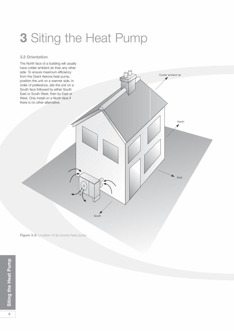
The North face of a building will usuallyhave colder ambient air than any otherside. To ensure maximum efficiencyfrom the Grant Aerona heat pump,position the unit on a warmer side. Inorder of preference, site the unit on aSouth face followed by either SouthEast or South West, then by East orWest. Only install on a North face ifthere is no other alternative.
3.2 Orientation
North
Cooler ambient air
East
South
Figure 3-2: Location of air source heat pump
Hyd
raul
ic D
iag
ram
s
9
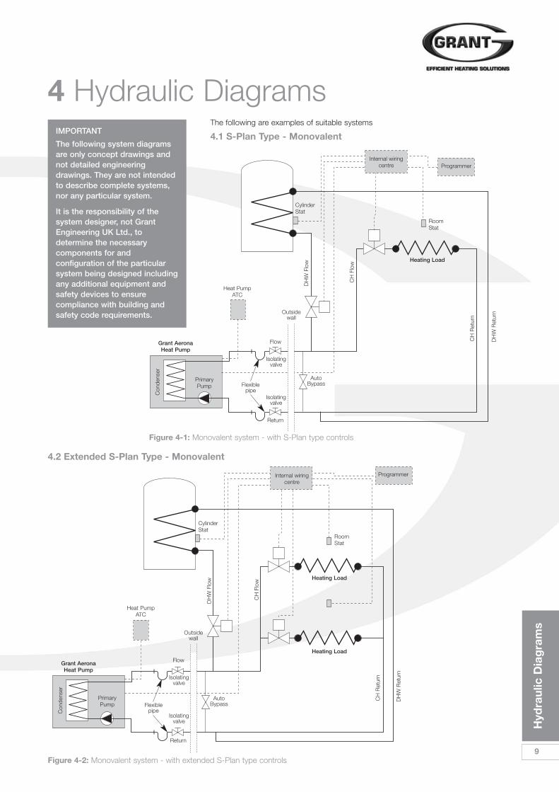
4 Hydraulic Diagrams 4.1 S-Plan Type - Monovalent
4.2 Extended S-Plan Type - Monovalent
Heat PumpATC
Heat PumpATC
Flow
Flexiblepipe
AutoBypass
Isolatingvalve
Isolatingvalve
Return
CH
Flo
w
DH
W F
low
CH
Ret
urn
DH
W R
etur
n
CH
Ret
urn
DH
W R
etur
n
CylinderStat
RoomStat
Internal wiringcentre
Heating Load
Heating Load
Heating Load
Programmer
Grant AeronaHeat Pump
PrimaryPump
Con
dens
er
CH
Flo
w
DH
W F
low
CylinderStat
RoomStat
Internal wiringcentre
Programmer
Figure 4-1: Monovalent system - with S-Plan type controls
Figure 4-2: Monovalent system - with extended S-Plan type controls
Outsidewall
Outsidewall
Flow
Flexiblepipe
AutoBypass
Isolatingvalve
Isolatingvalve
Return
Grant AeronaHeat Pump
PrimaryPump
Con
dens
er
The following are examples of suitable systemsIMPORTANT
The following system diagramsare only concept drawings andnot detailed engineeringdrawings. They are not intendedto describe complete systems,nor any particular system.
It is the responsibility of thesystem designer, not GrantEngineering UK Ltd., todetermine the necessarycomponents for andconfiguration of the particularsystem being designed includingany additional equipment andsafety devices to ensurecompliance with building andsafety code requirements.

10
Hyd
raul
ic D
iag
ram
s
4 Hydraulic Diagrams
4.3 S-Plan Type - Bivalent
CH FlowDHW Flow
Heating LoadD
HW
Ret
urn
CH
Ret
urn
RoomStat
Internal wiringcentre
Programmer
Boiler
200mm
minimum
R F
CylinderStat
The following are examples of suitable systems
Figure 4-4: Bivalent system - with boiler manifold and S-Plan type controls
Outsidewall
Auto Bypass
Boilermanifold
Flow
Flexiblepipe
Isolatingvalve
Isolatingvalve
Return
Grant AeronaHeat Pump
PrimaryPump
Con
dens
er
Heat PumpATC
IMPORTANT
The following system diagrams areonly concept drawings and notdetailed engineering drawings. They are not intended to describecomplete systems, nor anyparticular system.
It is the responsibility of the systemdesigner, not Grant Engineering UKLtd., to determine the necessarycomponents for and configuration ofthe particular system beingdesigned including any additionalequipment and safety devices toensure compliance with buildingand safety code requirements.

Hyd
raul
ic D
iag
ram
s
11
200mm
minimum
CH FlowDHW Flow
Outsidewall
4.4 Extended S-Plan Type - Bivalent
Heating Load
Heating Load
DH
W R
etur
n
CH
Ret
urn
RoomStat
RoomStat
Internal wiringcentre
Programmer
Boiler
R F
CylinderStat
Figure 4-6: Bivalent system - with boiler manifold and extended S-Plan type controls
Auto Bypass
Flow
Flexiblepipe
Isolatingvalve
Isolatingvalve
Return
Grant AeronaHeat Pump
PrimaryPump
Con
dens
er
Heat PumpATC
Boilermanifold
12
Hyd
raul
ic D
iag
ram
s
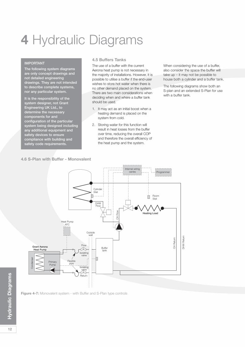
4 Hydraulic Diagrams 4.5 Buffers Tanks
4.6 S-Plan with Buffer - Monovalent
The use of a buffer with the currentAerona heat pump is not necessary inthe majority of installations. However, it ispossible to utilise a buffer if the end-userwishes to store hot water when there isno other demand placed on the system.There are two main considerations whendeciding when and where a buffer tankshould be used.
1. It may act as an initial boost when aheating demand is placed on thesystem from cold.
2. Storing water for this function willresult in heat losses from the bufferover time, reducing the overall COPand therefore the overall efficiency ofthe heat pump and the system.
When considering the use of a buffer,also consider the space the buffer willtake up – it may not be possible tohouse both a cylinder and a buffer tank.
The following diagrams show both anS-plan and an extended S-Plan for usewith a buffer tank.
CH
Flo
w
DHWFlow
CylinderStat
RoomStat
Internal wiringcentre
Heating Load
Programmer
Flow
Flexiblepipe
Buffertank
Isolatingvalve
Isolatingvalve
Return
Grant AeronaHeat Pump
PrimaryPump
Con
dens
er
Heat PumpATC
Figure 4-7: Monovalent system - with Buffer and S-Plan type controls
CH
Ret
urn
DH
W R
etur
n
Outsidewall
IMPORTANT
The following system diagramsare only concept drawings andnot detailed engineeringdrawings. They are not intendedto describe complete systems,nor any particular system.
It is the responsibility of thesystem designer, not GrantEngineering UK Ltd., todetermine the necessarycomponents for andconfiguration of the particularsystem being designed includingany additional equipment andsafety devices to ensurecompliance with building andsafety code requirements.
Hyd
raul
ic D
iag
ram
s
13
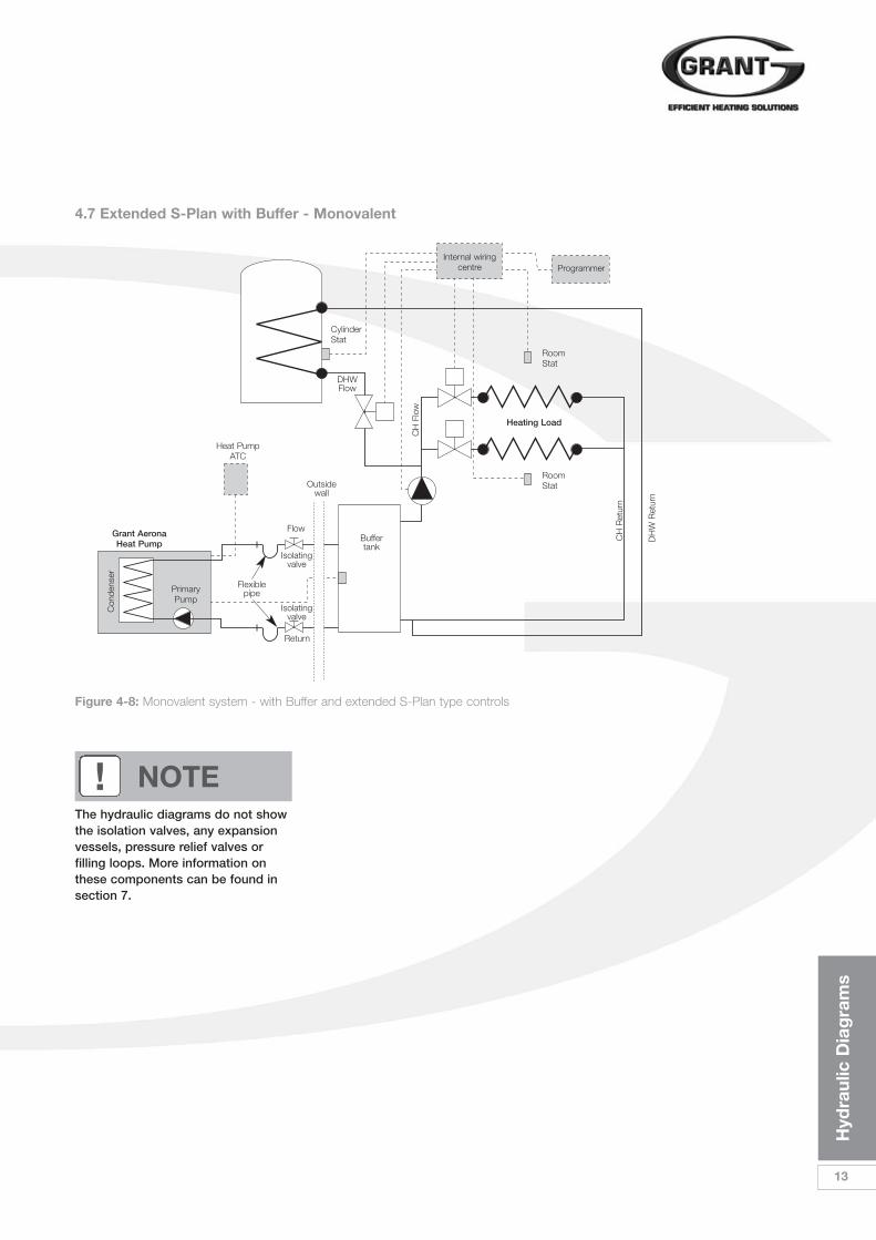
4.7 Extended S-Plan with Buffer - Monovalent
CylinderStat
RoomStat
RoomStat
Internal wiringcentre
Heating Load
Programmer
The hydraulic diagrams do not showthe isolation valves, any expansionvessels, pressure relief valves orfilling loops. More information onthese components can be found insection 7.
! NOTE
Figure 4-8: Monovalent system - with Buffer and extended S-Plan type controls
CH
Flo
w
DHWFlow
Flow
Flexiblepipe
Buffertank
Isolatingvalve
Isolatingvalve
Return
Grant AeronaHeat Pump
PrimaryPump
Con
dens
er
Heat PumpATC
CH
Ret
urn
DH
W R
etur
n
Outsidewall

14
Sys
tem
Des
ign
Cri
teri
a
Unlike a typical condensing oil or gasfired boiler that operates at a flow of70˚C and a return of 50˚C, a heat pumpoperates with a flow of between 30˚Cand 60˚C. The return temperature willdepend on the load of the system at agiven point in time.
The design of any system in the UK istypically based on 2 parameters.
1. That the outside air temperaturecan fall to as low as -3˚C and thatthe house comfort temperature willbe 21˚C. The BTC incorporated in the heatpump will adjust the outputaccording to the external ambientair temperature but the systemmust be designed in the first placeto meet this maximum demand.
2. The second factor to consider isachieving this maximum demandusing much lower watertemperatures than with oil or gasfired appliances.
Designing a new system for use with a low-grade heat source is straight forward, and assuming the insulation properties of the dwelling meets or exceeds current building regulations, there should be no issue with achieving the heat demand.
The use of a heat pump in an existingsystem can be straightforward if thefollowing rules are followed.
1. The loft has insulation to a depth of 270mm
2. Cavity wall insulation has beeninstalled
3. The radiators have been changed or upgraded to match the new water temperature
4. An accurate heat loss calculation for each room of the house hasbeen carried out
5. All primary and secondary pipeshave been well insulated to preventheat loss
While underfloor heating is the preferredheat emitter, a combination ofunderfloor heating and radiators, orradiators only, works just as efficiently. Itis necessary, however, to calculate thesize of radiator required accurately – if this is not done, the house will fail to reach the target temperature and willbe costly to rectify after the installationis complete.
Refer to Section 6 to determine the sizeof radiators required for yourinstallation.
5 System Design Criteria
It must be understood that your final designworking temperature will have an effect on theoverall system efficiency, the COP of the heat pumpand the complete system. Put simply, the loweryour design working temperature, the better theCOP. If you are in any doubt about the suitability ofthe heating system, stop and seek the advice of aqualified heating engineer or experienced systemdesigner.

Cal
cula
ting
R
adia
tor
Siz
es
15
Most existing wet heating systems willuse radiators as emitters. When theoriginal system was installed, theradiators would have been sizedaccording to the manufacturer’sspecifications. Typically, this would havebeen 82ºC flow and 71ºC return withthe connections being flow at the topand return at the opposite bottomcorner.
Existing systems
With the advent of condensing boilers,most installations were found to haveoversized radiators and as such, little orno adverse effects were found whenthe system temperatures fell to 70ºCflow and 50ºC return.
However, as heat pumps work attemperatures lower than even this, it isimportant that each radiator is checkedagain for its suitability and replaced withone of the correct size/output ifnecessary.
As can be seen, the size of radiatorrequired will be larger than conventionalsystems. This can be controlled to anextent by choosing a suitable designwater temperature. The trade off will bea slightly lower COP. As we havealready discussed, the higher therunning temperature, the harder theheat pump has to work to reach thedesired temperature.
Please advise the customer that, inany case, the radiator will not get‘hot’. The perception may well bethat the system is not workingcorrectly because the radiators areonly ‘warm’.
Below is a typical radiator conversation factor table* and a worked example of sizing radiators for use with a heat pump
A typical heat pump operating to feed radiators will run at a flow temperature of 50ºCand a return temperature of 40ºC – giving a mean water temperature of 45ºC.
In the case of a system using both radiators and Underfloor heating (UFH) a flow of40°C and a return of 30ºC – giving a mean water temperature of 35ºC – would usuallybe preferred.
For a living room with a design temperature of 21ºC and heat loss of 1.8kW.
The ΔT = 45ºC – 21ºC = 24ºC.
From the radiator manufacturers correction factor table: for ΔT = 24°C factor ≈ 0.406.
For a design heat loss of 1.8 kW: the required corrected output is 1.8 / 0.406 = 4.43kW.
Select a radiator from manufacturer’s information that would give 4.43kW output (at75°C mean water temperature) – this will give the required 1.8 kW output at 45°Cmean water temperature produced by the heat pump.
Similarly, for a bedroom with the same design heat loss but design temperature of 18°C.
The ΔT = 45°C – 18°C = 27°C.
From the radiator manufacturers correction factor table: for ΔT = 27°C factor ≈ 0.46.
For a design heat loss of 1.8 kW: the required corrected output is 1.8 / 0.46 = 3.48kW.
Thus, select a radiator from manufacturer’s information that would give 3.48kW outputto give the required 1.8 kW output at 45°C mean water temperature.
For an UFH system with a mean water temperature of 35°C.
For a design heat loss of 1.8kW and a design room temperature of 18°C.
The ΔT = 35°C – 18°C = 17°C.
From the radiator manufacturers correction factor table: for ΔT = 17°C factor ≈ 0.26.
For a design heat loss of 1.8 kW: the required corrected output is 1.8 / 0.26 = 6.92kW.
Thus, select a radiator from manufacturer’s information that would give 6.92 kW outputto give the required 1.8 kW output at 35°C mean water temperature.
* Where possible reference should be made to radiator manufacturers owninformation for the correction factors for different types of radiator.
6 Calculating Radiator Sizes
ºC Correction Factor
5 0.050
10 0.123
15 0.209
20 0.304
25 0.406
30 0.515
35 0.629
40 0.748
45 0.872
50 1.000
55 1.132
60 1.267
65 1.406
70 1.549
75 1.694

16
Sea
led
Sys
tem
s
The following components are requiredto use the Grant Aerona heat pump aspart of a sealed heating system. Due tothe lack of space these componentsare not located within the heat pump,but have to be fitted external to theunit.
a) expansion vessel (of the correct sizeto suit the volume of the system)
b) Pressure relief valve – 3 bar
c) Pressure gauge
d) Filling loop
e) Tundish
These items may already be installed onthe existing system. If so, they shouldbe checked to ensure the integrity andsuitability of the components beforeproceeding to re-use them.
Refer to Section 14 for details of theGrant sealed system kits designed foruse with the Grant Aerona heat pumprange.
The expansion vessel can be fitted toeither the flow or return pipes butensure that there is no automatic ormanual valve in line that may preventthe heat pump utilising the expansionvessel.
The filling loop can be sited anywhere inthe system, but it must always be sitedwithin visual distance of the pressuregauge. The nominal filling pressure forthe system when cold is 1 bar.
Before filling the system check theexpansion vessel charge pressure. Thisshould be 0.2 – 0.3 bar higher than thecold fill pressure for the system.
It is good practice to have automatic airvents at all high points of the system,particularly where pipes fall vertically –e.g. drop feed systems. The immersionunit within the heat pump has a factoryfitted manual air vent.
7 Sealed Systems
CylinderStat
RoomStat
Internal wiringcentre
Heating Load
Programmer
Expansionvessel
PressureGauge
FillingLoop
RaisingMain
Figure 7-1: Sealed system layout
Outsidewall
AutoBypass
Flow
Flexiblepipe
Isolatingvalve
Isolatingvalve
Return
Grant AeronaHeat Pump
PrimaryPump
Con
dens
er
Heat PumpATC
CH
Flo
w
DH
W F
low
CH
Ret
urn
DH
W R
etur
n

Ele
ctri
cal
17
8.1 GeneralThe Grant Aerona Heat Pump is very simple to install and to wire. The units are designedto meet the need for simplicity – both in installation and in servicing. As a result, thewiring involved is both minimal and simple compared to other heat pumps available.
For Monovalent systems, the following cables are required.
a) 1 x twin and earth cable suitable for the current and length of run from theconsumer board to the external isolator.
b) 1 x 3-core SWA suitable for the current from the external isolator to the heatpump.
c) 1 x 3-core 0.75mm² from the systems wiring centre to the heat pump
d) 1 x 3-core umbilical cable from the heat pump to the ATC (heat pump controller)mounted inside the house. A 5m length of this cable, complete with fitted plugs issupplied with the heat pump.
For Bivalent systems, an additional 2-core 0.75mm² cable is required from the heatpump to the boiler.
8.2 Basic Circuits – Making the ConnectionThe diagram below is of a typical S-Plan type control system as used with a gas or oil fired boiler.
FOR INFORMATION ONLY – DO NOT FOLLOW THIS DIAGRAM AS IT WILL CAUSE IRREPARABLEDAMAGE TO THE HEAT PUMP.
8 Electrical
IMPORTANT
All electrical work must be undertaken by a competent person. failure to observethis legislation could result in an unsafe installation and will invalidate all warranties.
Hlg
Zon
e Va
lve
DH
W Z
one
Valv
e
E
L N
L N E 4 5 6 7 8 9 10
1
2
3
1Limit Control
Boiler & SystemCirculation Pump
2
c
1 2
c
ProgrammerRoom
Thermostat
CH
HW
Gr
Br
O
Bl
Off
E
Gr
Br
O
Bl
Off
Note that the two wires that feedboth motorised valves to Gr (grey)terminate at L, giving them apermanent supply of 230Vac. The two wires leaving the motorisedvalves at O (orange) are the switchedoutput and will also be at mainspotential. The switches inside themotorised valves make theconnection between L (permanentLive) and 10 (switch live) to feed theboiler and the pump.
In contrast, the heat pump switchesat 0V and therefore a simple re-wiring(for existing systems) must takeplace at the wiring centre before it issafe to connect to the heat pump.
! NOTE
It is possible for some componentsto have 2 power supplies feedingthem. It is also possible for mistakingan internal circuit to be dead when itis receiving power from anothersource. Please label all controls anddevices if this is possible, advising tocheck and isolate in one or morelocations as required.
To help remove as much of this risk as possible, take all heating system,heat pump and immersion elementcircuits from a single supply at theconsumer unit.
! NOTE
Figure 8-1: S-Plan type system for normal boiler connection

18
Ele
ctri
cal
8 Electrical
Earth connections havebeen excluded for clarity.Ensure all earthconnections are madeprior to energising.
Within the heat pump control panel, connect the wires as follows:
Wiring Centre Heat Pump
8 1 – Common
9 2 – Heating
10 3 – DHW
For multiple heating zone valves, follow the above and join all oranges from the heating motorised valves into 9 in the wiring centre, and all greys to terminal 8.
Hlg
Zon
e Va
lve
DH
W Z
one
Valv
e
E
L N
L N E 4 5 6 7 8 9 10
1
2
3
1
Limit Control
2
c
1 2
c
ProgrammerRoom
Thermostat
CH
HW
Gr
Br
O
Bl
Off
E
Gr
Br
O
Bl
Off
Note that both wires from Gr (grey)now terminate on their own atposition 8. The wires from O (orange)from each valve now terminate ontheir own at positions 9 and 10. Thefeed from the cylinder thermostatand the feed to Br (brown) on theDHW motorised valve, nowterminates at position 7. When thatis completed, the 3-core 0.75mm²cable can now connect at positions8, 9 and 10.
! NOTE
Figure 8-2: S-Plan type system for connection to Aerona heat pump
Ele
ctri
cal
19
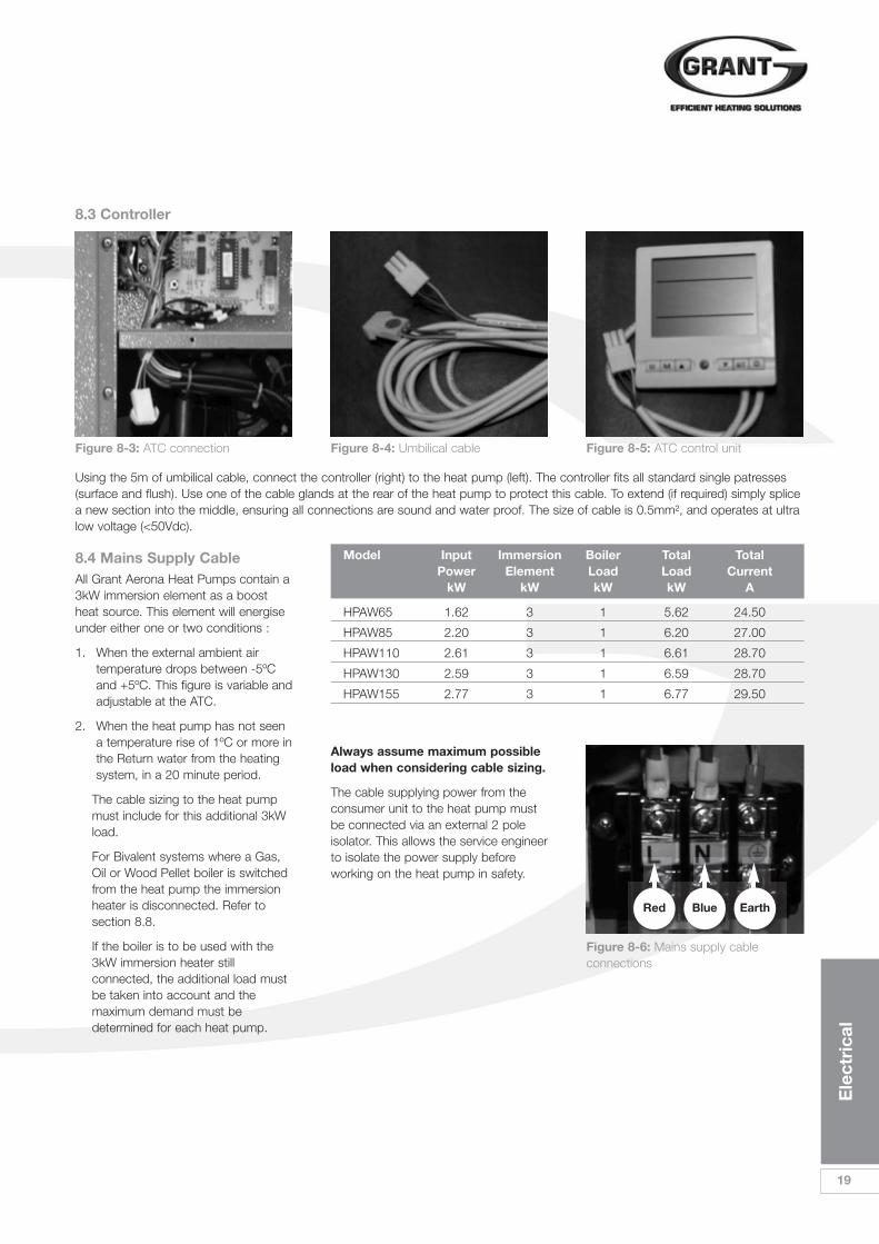
8.4 Mains Supply CableAll Grant Aerona Heat Pumps contain a3kW immersion element as a boostheat source. This element will energiseunder either one or two conditions :
1. When the external ambient airtemperature drops between -5ºCand +5ºC. This figure is variable andadjustable at the ATC.
2. When the heat pump has not seena temperature rise of 1ºC or more inthe Return water from the heatingsystem, in a 20 minute period.
The cable sizing to the heat pump must include for this additional 3kW load.
For Bivalent systems where a Gas, Oil or Wood Pellet boiler is switched from the heat pump the immersion heater is disconnected. Refer to section 8.8.
If the boiler is to be used with the 3kW immersion heater still connected, the additional load must be taken into account and the maximum demand must be determined for each heat pump.
8.3 Controller
Using the 5m of umbilical cable, connect the controller (right) to the heat pump (left). The controller fits all standard single patresses(surface and flush). Use one of the cable glands at the rear of the heat pump to protect this cable. To extend (if required) simply splicea new section into the middle, ensuring all connections are sound and water proof. The size of cable is 0.5mm², and operates at ultralow voltage (<50Vdc).
Model Input Immersion Boiler Total TotalPower Element Load Load Current
kW kW kW kW A
HPAW65 1.62 3 1 5.62 24.50
HPAW85 2.20 3 1 6.20 27.00
HPAW110 2.61 3 1 6.61 28.70
HPAW130 2.59 3 1 6.59 28.70
HPAW155 2.77 3 1 6.77 29.50
Always assume maximum possibleload when considering cable sizing.
The cable supplying power from theconsumer unit to the heat pump mustbe connected via an external 2 poleisolator. This allows the service engineerto isolate the power supply beforeworking on the heat pump in safety.
Figure 8-6: Mains supply cableconnections
Red Blue Earth
Figure 8-3: ATC connection Figure 8-4: Umbilical cable Figure 8-5: ATC control unit

20
Ele
ctri
cal
8.5 Heat Pump Wiring Diagram
8 Electrical
The Main Connections you have to make
230 Vac
CompressorHeater
4-wayvalve
Expansion Valve
DisconnectElectric Elementfor BivalentSwitched Output
Ret Gas SensorExt Temp Sensor
Coil Temp SensorDis Gas SensorRet Temp Sensor
N
Compressor
Fanmotor
PumpRelayKM2
3kWElectricElement
Orange
Red
Blu
e
Whi
te
Blk
Power SupplyTerminal
3 Connection points for installer
ATC ControllerSocket S-Plan Controls
Connections
3 2 1 3 2 1
121110987654321
242322212019181716151413C
R S
24 Vac
Fuse
Rel
ay K
M1
Low
pre
ssur
e sw
itch
Hig
h pr
essu
re s
witc
h
ATC controllersocket
S-Plan controlsconnections
Power supplyterminal
Figure 8-7: Heat pump connection diagram for 3kW electrical element
Figure 8-8: Location of connections in control panel
Ele
ctri
cal
21
230 Vac
CompressorHeater
4-wayvalve
Expansion Valve
Ret Gas SensorExt Temp Sensor
Coil Temp SensorDis Gas SensorRet Temp Sensor
N
Compressor
Fanmotor
PumpRelayKM2
6kWElectricElement
Orange
RedB
lue
Whi
te
Blk
Power SupplyTerminal
3 Connection points for installer
ATC ControllerSocket S-Plan Controls
Connections
3 2 1 3 2 1
121110987654321
242322212019181716151413C
R S
24 Vac
Fuse
Rel
ay K
M1
Low
pre
ssur
e sw
itch
Hig
h pr
essu
re s
witc
h
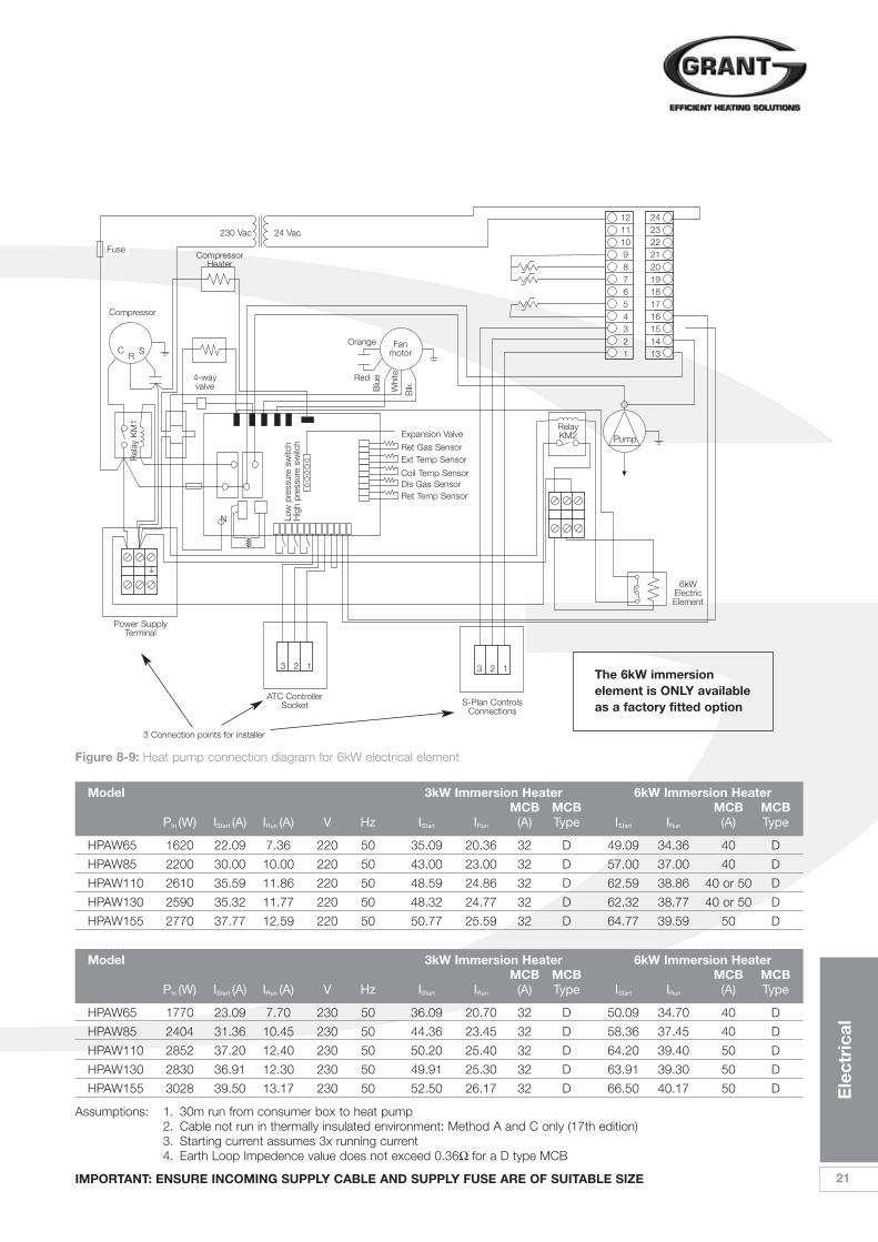
Figure 8-9: Heat pump connection diagram for 6kW electrical element
Model 3kW Immersion Heater 6kW Immersion HeaterMCB MCB MCB MCB
PIn (W) IStart (A) IRun (A) V Hz IStart IRun (A) Type IStart IRun (A) Type
HPAW65 1620 22.09 7.36 220 50 35.09 20.36 32 D 49.09 34.36 40 D
HPAW85 2200 30.00 10.00 220 50 43.00 23.00 32 D 57.00 37.00 40 D
HPAW110 2610 35.59 11.86 220 50 48.59 24.86 32 D 62.59 38.86 40 or 50 D
HPAW130 2590 35.32 11.77 220 50 48.32 24.77 32 D 62.32 38.77 40 or 50 D
HPAW155 2770 37.77 12.59 220 50 50.77 25.59 32 D 64.77 39.59 50 D
Model 3kW Immersion Heater 6kW Immersion HeaterMCB MCB MCB MCB
PIn (W) IStart (A) IRun (A) V Hz IStart IRun (A) Type IStart IRun (A) Type
HPAW65 1770 23.09 7.70 230 50 36.09 20.70 32 D 50.09 34.70 40 D
HPAW85 2404 31.36 10.45 230 50 44.36 23.45 32 D 58.36 37.45 40 D
HPAW110 2852 37.20 12.40 230 50 50.20 25.40 32 D 64.20 39.40 50 D
HPAW130 2830 36.91 12.30 230 50 49.91 25.30 32 D 63.91 39.30 50 D
HPAW155 3028 39.50 13.17 230 50 52.50 26.17 32 D 66.50 40.17 50 D
Assumptions: 1. 30m run from consumer box to heat pump2. Cable not run in thermally insulated environment: Method A and C only (17th edition)3. Starting current assumes 3x running current4. Earth Loop Impedence value does not exceed 0.36W for a D type MCB
IMPORTANT: ENSURE INCOMING SUPPLY CABLE AND SUPPLY FUSE ARE OF SUITABLE SIZE
The 6kW immersionelement is ONLY availableas a factory fitted option

22
Ele
ctri
cal
8 ElectricalH
lg Z
one
Valv
e
MC
B
E
L N
L N E 4 5 6 7 8 9 10
1
2
3
1Limit Control
2
c
1 2
c
ProgrammerRoom
Thermostat
CylinderThermostat
CH
HW
Gr
Br
O
Bl
Off
Figure 8-11: Central Heating connection diagram
HW
CH
C
Heat pump S-Plan controlsconnections
3
2
1
230V 50Hz
L N
MC
B
DH
W Z
one
Valv
e
L N
L N E 4 5 6 7 8 9 10
1
2
3
1Limit Control
HW
CH
C
Heat pump S-Plan controlsconnections
3
2
1
2
c
1 2
Programmer
230V 50Hz
RoomThermostat
CH
HW
E
Gr
Br
O
Bl
Off
L N
8.6 System Control Wiring Diagrams
Figure 8-10: Domestic hot water connection diagram

Ele
ctri
cal
23
8.7 Wiring Diagrams
L N E 4 5 6 7 8 9 10
1Limit
2
c
1Control
2
c
Programmer
Fuse
CH HW
Fuse
Fuse
HIg Zone Valve
MC
B
L
L
Off
O
Bl
Br
Gr
Off
O
Bl
Br
Gr
DHW Zone Valve
Returnsensor
Outdoorsensor
Supply sensor
230V/24 VacTransformer
N1 3
N
RoomThermostat
Cylinder Thermostat
12 24
23
22
21
20
19
18
17
16
15
14
13
Relay 2 in heatpump control
panel
Boiler
11
10
9
8
7
6
5
4
3
2
1
BTC
Heat PumpPCH
Controller
Compressor
Circulating Pump
2
L
N
Figure 8-12: Bivalent system connection diagram
HW CH C
3 2 1 Heat pump S-Plan controlsconnections
230V 50Hz
24
Ele
ctri
cal
8 Electrical
L N E 4 5 6 7 8 9 10
1Limit
2
c
1Control
2
c
Programmer
Fuse
CH HW
Fuse
Fuse
HIg Zone Valve
MC
B
L
L
Off
O
Bl
Br
Gr
Off
O
Bl
Br
Gr
DHW Zone Valve
230V/24 VacTransformer
N1 3
N
RoomThermostat
Cylinder Thermostat
3 kWImmersionelement
12 24
23
22
21
20
19
18
17
16
15
14
13
11
10
9
8
7
6
5
4
3
2
1
BTC
Heat PumpPCH
Controller
Compressor
Circulating Pump
2
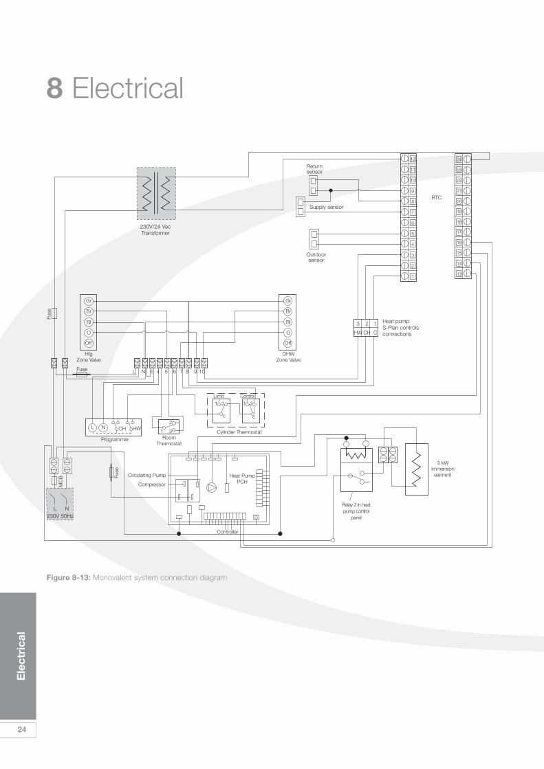
Figure 8-13: Monovalent system connection diagram
HW CH C
3 2 1 Heat pump S-Plan controlsconnections
230V 50Hz
Returnsensor
Outdoorsensor
Supply sensor
Relay 2 in heatpump control
panel

Ele
ctri
cal
25
8.9 Extending the ElectricsIt may be part of the system design toincorporate Solar Thermal into thedesign.
This is easily done with the use of anadditional two-pole relay. Following thediagram in Figure 8-13 below will givethe solar thermal system a priority overthe heat pump when there is a demandfor DHW only.
This can, of course be added to bothmonovalent and bivalent systems. It ismuch easier to carry out all these typesof systems based on S-plan typecontrols only.
Y and W type plans can be used, butthe need for additional relays is notpractical. It is much easier to convert Yand W type plans to S types from thestart.
8.8 Bivalent SystemsFor bivalent systems, it is necessary todisconnect the internal immersionelement from the relay inside the heatpump control panel. Taking the live andneutral outputs from this relay extendthis wire to the boiler. Isolate this cablethrough a fused double pole spurswitch and mark on the switch that thesupply comes from the heat pump.
Follow the wiring diagram as shown inFigure 8-11 for a bivalent system.
MC
B
230V50Hz
L N E 4 5 6 7 8 9 10
1Limit
2
c
1Control
2
c
Programmer
Heatingzonevalve
CH HW
Fuse
Fuse
L
Off
O
Bl
Br
Gr
Off
O
Bl
Br
Gr
DHW Zone Valve
Relay 3
N 1 3Room
Thermostat
Cylinder Thermostat
L
N
E
E
N
L
In
Out
Solarpump
Solar controller
Panelsensor
Cylindersensor
2
Figure 8-14: Connection diagram for Grant solar thermal system
C CH HW
1 2 3 Heat pump S-Plan controlsconnections
IMPORTANT
Do not take the Neutral from the heat pump to feed the boiler circuit. This will createan imbalance at the MCB and cause nuisance tripping. Always take the neutralsupply from the existing S-Plan wiring centre.

26
Do
mes
tic
Ho
t W
ater
9.1 Temperature ControlThe desired hot water temperaturestored in the cylinder can be adjustedon the BTC controller. As alreadymentioned, the heat pump works mostefficiently at lower temperatures butthese temperatures are not suitable fordomestic hot water which shouldalways be stored at about 60ºC.
9.2 Heat Pump CylindersAs the water temperature from the heatpump is lower than traditional systems,a much larger coil is required inside thecylinder to transfer the heat efficiently.
Grant Engineering has a range of 7stainless steel cylinders from 90 litres to300 litres with coil areas of up to 3.5m².Visit www.grantuk.com for more
information. These cylinder have been designed to match the outputfrom the Grant Aerona heat pumps formaximum efficiency and faster re-heattimes when compared to standard typeindirect cylinders.
9.3 Temperature BoostIt is possible to use the heat pump toraise the DHW temperature to 60ºC.During the summer, this may bepreferable, when the external ambientair temperature is high. However, duringthe winter, it would not be economicalfor any heat pump to try to raise thewater temperature to this level.
As a result, Grant has developed acontrol system that will take thetemperature of the existing cylinderfrom 45°C to 60°C, after the cylinderthermostat has switched off the hotwater operation of the heat pump.
This system uses both the existingcylinder immersion element and cylinderthermostat, but operated via an ‘add-on’ relay and override switch enclosedin a separate unit to be mounted nextto the cylinder. This system is fullyautomatic but can be overridden by theuser if required, i.e. the user can switchon the immersion element using theoverride switch to manually boost thehot water cylinder temperature.
9 Domestic Hot Water
The DHW boost pack contains a power relay and an additional 2-pole isolator.
L N E 4 5 6 7 8 9 10
1Limit
2
c
1Control
2
c
Programmer
Fuse
Fuse
Fuse
HIg Zone Valve
MC
B
230V 50HzL
L
Off
O
Bl
Br
Gr
Off
O
Bl
Br
Gr
DHW Zone Valve
To domestic hot water boosterrelay coil (see Figure 9-2)
230V/24 VacTransformer
N1 3
N
RoomThermostat
Cylinder Thermostat
Imm
ersi
on e
lem
ent
12 2423
22
21
20
19
18
17
16
15
14
13
11
10
9
8
7
6
5
4
3
2
1
BTC
Heat PumpPCH
Controller
Compressor
2
HW CH C
3 2 1 Heat pump S-Plan controlsconnections
Figure 9-1: Connection diagram for DHW booster system
CH HW
Returnsensor
Outdoorsensor
Supply sensor
Relay 2 in heatpump control
panel

Do
mes
tic
Ho
t W
ater
27
NB. Setting this override switch to OFFdoes not stop the automatic operationof the immersion element.
The required relay, manual overrideswitch and enclosure are available fromGrant Engineering UK Ltd as a kit. Fordetails of this Automatic Domestic HotWater Boost Kit (Grant Ref.HPDHWBK1) refer to Section 15 ofthese instructions.
When fitted, this kit interrupts theelectrical supply between the existingimmersion heater and the fusedimmersion switch. Refer to Figures 9-1and 9-2 for electrical connection details.
With the cylinder thermostat set to45°C, when the heat pump raises theDHW cylinder to this temperature, thecylinder thermostat switches to the‘satisfied’ position. The resultingswitched live from the auxiliary (normallyopen) contact of the cylinder thermostat
operates the relay in the booster kit andenergises the existing immersionelement in the cylinder, controller andprotected by its internal thermostat andlimit thermostat.
The immersion heater thermostatshould be set to 60°C
When hot water is drawn off, if thetemperature falls below 45°C thecylinder thermostat will detect the dropin cylinder temperature, creating ademand for the heat pump to operateto re-heat the cylinder. The switchedlive to the boost kit relay will cease andthe immersion element is de-energised.
If the temperature detected by thecylinder thermostat does not fall to45°C the immersion element willcontinue to operate, via the relay, to re-heat the cylinder.
Supply from cylinderthermostat auxiliary contact
Immersionelement
FusedImmersion
switch
NB: No connection toLoad N terminal isrequired
L
Supply
Load
N
L
N
Relay Overrideswitch
A1 A2L N
L NL1 T2
Figure 9-3: DHW booster kit with cover removed to show relay
Figure 9-2: Connection of immersion element using DHW booster kit
IMPORTANTThis domestic hot waterbooster pack is optional and isonly used if the customerwants the most efficient formof heating their hot water. Ifnot, then the BTC can beprogrammed to deliver hotwater up to 60ºC with noadditional wiring.
IMPORTANTFor this system to operate theexisting immersion switch mustbe left set permanently to ON.
To totally prevent operation ofthe immersion element theexisting immersion switch mustbe set to OFF.
Earth connectionsbetween fused immersionswitch, override switchand immersion elementnot shown.
Two separate power supplies areconnected to the DHW boost kit. Donot install or work on this kit, orremove the switch or cover, withoutensuring that BOTH supplies areisolated.
! WARNING
28
Filli
ng t
he S
yste
m
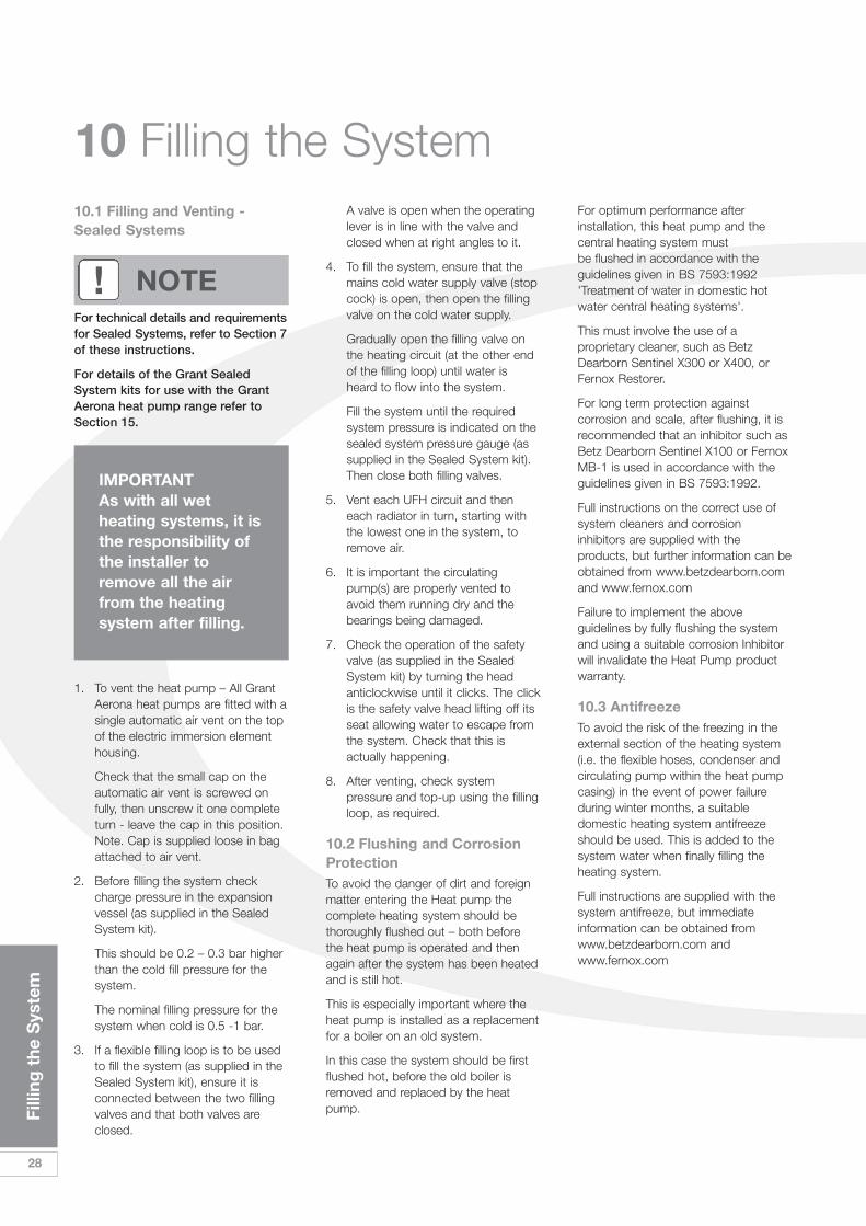
10 Filling the System10.1 Filling and Venting -Sealed Systems
1. To vent the heat pump – All GrantAerona heat pumps are fitted with asingle automatic air vent on the topof the electric immersion elementhousing.
Check that the small cap on theautomatic air vent is screwed onfully, then unscrew it one completeturn - leave the cap in this position.Note. Cap is supplied loose in bagattached to air vent.
2. Before filling the system checkcharge pressure in the expansionvessel (as supplied in the SealedSystem kit).
This should be 0.2 – 0.3 bar higherthan the cold fill pressure for thesystem.
The nominal filling pressure for thesystem when cold is 0.5 -1 bar.
3. If a flexible filling loop is to be usedto fill the system (as supplied in theSealed System kit), ensure it isconnected between the two fillingvalves and that both valves areclosed.
A valve is open when the operatinglever is in line with the valve andclosed when at right angles to it.
4. To fill the system, ensure that themains cold water supply valve (stopcock) is open, then open the fillingvalve on the cold water supply.
Gradually open the filling valve onthe heating circuit (at the other endof the filling loop) until water isheard to flow into the system.
Fill the system until the requiredsystem pressure is indicated on thesealed system pressure gauge (assupplied in the Sealed System kit).Then close both filling valves.
5. Vent each UFH circuit and theneach radiator in turn, starting withthe lowest one in the system, toremove air.
6. It is important the circulatingpump(s) are properly vented toavoid them running dry and thebearings being damaged.
7. Check the operation of the safetyvalve (as supplied in the SealedSystem kit) by turning the headanticlockwise until it clicks. The clickis the safety valve head lifting off itsseat allowing water to escape fromthe system. Check that this isactually happening.
8. After venting, check systempressure and top-up using the fillingloop, as required.
10.2 Flushing and CorrosionProtection To avoid the danger of dirt and foreignmatter entering the Heat pump thecomplete heating system should bethoroughly flushed out – both beforethe heat pump is operated and thenagain after the system has been heatedand is still hot.
This is especially important where theheat pump is installed as a replacementfor a boiler on an old system.
In this case the system should be firstflushed hot, before the old boiler isremoved and replaced by the heatpump.
For optimum performance afterinstallation, this heat pump and thecentral heating system must be flushed in accordance with theguidelines given in BS 7593:1992'Treatment of water in domestic hotwater central heating systems'.
This must involve the use of aproprietary cleaner, such as BetzDearborn Sentinel X300 or X400, orFernox Restorer.
For long term protection againstcorrosion and scale, after flushing, it isrecommended that an inhibitor such asBetz Dearborn Sentinel X100 or FernoxMB-1 is used in accordance with theguidelines given in BS 7593:1992.
Full instructions on the correct use ofsystem cleaners and corrosioninhibitors are supplied with theproducts, but further information can beobtained from www.betzdearborn.comand www.fernox.com
Failure to implement the aboveguidelines by fully flushing the systemand using a suitable corrosion Inhibitorwill invalidate the Heat Pump productwarranty.
10.3 AntifreezeTo avoid the risk of the freezing in theexternal section of the heating system(i.e. the flexible hoses, condenser andcirculating pump within the heat pumpcasing) in the event of power failureduring winter months, a suitabledomestic heating system antifreezeshould be used. This is added to thesystem water when finally filling theheating system.
Full instructions are supplied with thesystem antifreeze, but immediateinformation can be obtained fromwww.betzdearborn.com andwww.fernox.com
IMPORTANTAs with all wetheating systems, it isthe responsibility ofthe installer toremove all the airfrom the heatingsystem after filling.
For technical details and requirementsfor Sealed Systems, refer to Section 7of these instructions.
For details of the Grant SealedSystem kits for use with the GrantAerona heat pump range refer toSection 15.
! NOTE

Co
mm
issi
oni
ng
29
11 Commissioning11.1 Switching on First TimeWhen switching on for the first timecarry out the following procedures inthe order they appear.
1. Ensure the external mains powerisolation switch is set to the ‘OFF’position.
2. Energise the heating system insidethe house.
3. Create a CH demand using thetimer/programmer.
4. Confirm the CH motorised valvehas opened. (You may need toadjust the room thermostat toachieve this).
5. At the heat pump control panel,confirm there is no voltage presentbetween terminal 1 and 2 on the S-Plan connections in the HeatPump control panel – check there iscontinuity. If voltage is present(230Vac), check the wiring asshown on page 20 and correct asnecessary.
6. Remove CH demand.
7. Create a DHW demand (ifapplicable) using thetimer/programmer.
8. Confirm the DHW motorised valvehas opened. (You may need toadjust the cylinder thermostat toachieve this).
9. At the heat pump control panel,confirm there is no voltage presentbetween terminal 1 and 3 on the S-Plan connections in the HeatPump control panel – check there iscontinuity. If voltage is present(230Vac), check the wiring asshown on page 20 and correct asnecessary.
10. Create a CH and DHW demandusing the timer/programmer.
11. Confirm the CH and DHWmotorised valves have opened.
12. Switch the external isolator to ‘ON’.
13. Check power is established – theATC and BTC should now showdisplay default settings.
14. Set the ATC to automatic using the‘M’ button, and the display willshow the return temperature.
15. Within 30 seconds, the circulatingpump will start.
16. Within 30 seconds the fan will start.
17. Within 60 seconds the compressorwill start.
18. Once the compressor has started,pay attention to the pressure gaugeon the side of the heat pump. If thepointer starts to rise quickly, (entersthe yellow or red zone within 30seconds) switch off at the externalisolator and remove all air from thesystem.
19. When satisfied that all air has beenexpelled, start this process againfrom step 12.
20. Remove demand for CH and DHW.
21. Compressor and fan will stop.
22. Circulating pump will continue torun for a period of time (defaultsetting in BTC.).
23. Set the ATC and BTC - details insections 11.2 and 11.3 respectively.
IMPORTANTWhen putting the heat pump into use for the first time, watch the refrigerantpressure gauge on the side of the heat pump. The needle will rise over time whenthe temperature of the refrigerant increases. However, if this happens very quickly(e.g. rises into the yellow or red zone within 1 minute) then an air lock is present.Switch off power to the heat pump immediately, and purge any remaining air fromthe system.
IMPORTANT
Grant Aerona heat pumps should be stored andtransported in an upright position. If not, the heatpump MUST be positioned in an upright position forat least 4 hours before being operated.
30
Co
mm
issi
oni
ng
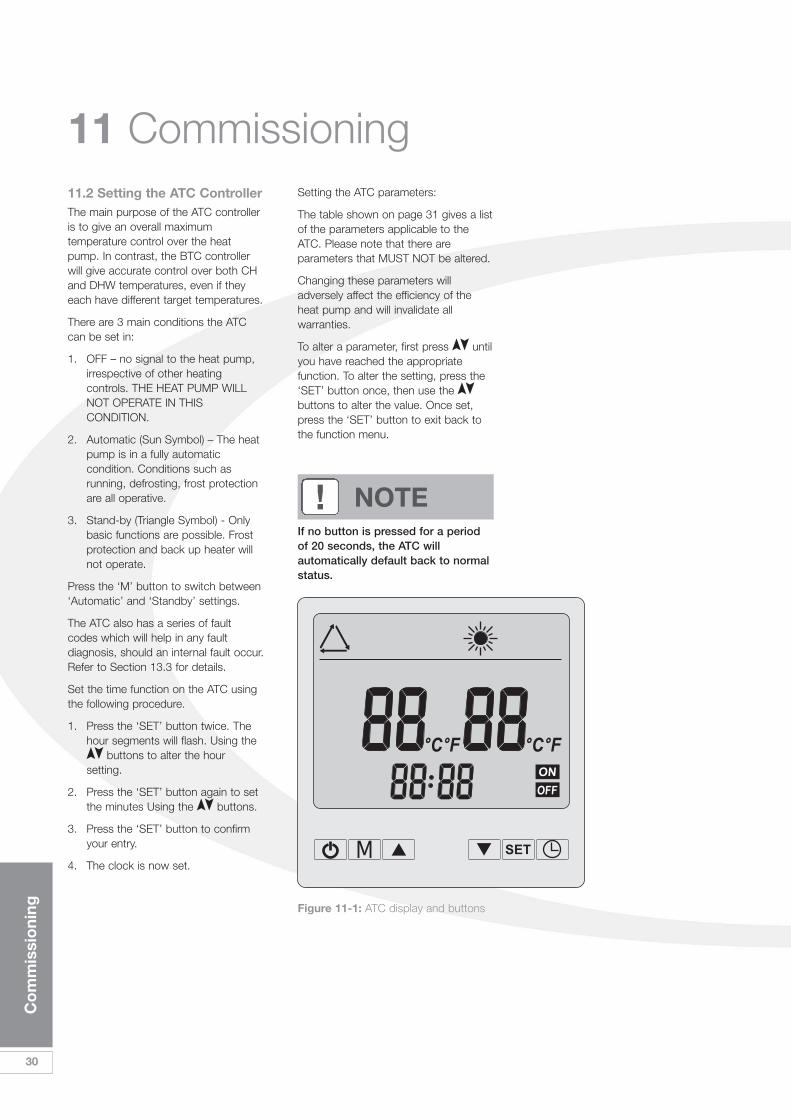
11 Commissioning11.2 Setting the ATC ControllerThe main purpose of the ATC controlleris to give an overall maximumtemperature control over the heatpump. In contrast, the BTC controllerwill give accurate control over both CHand DHW temperatures, even if theyeach have different target temperatures.
There are 3 main conditions the ATCcan be set in:
1. OFF – no signal to the heat pump,irrespective of other heatingcontrols. THE HEAT PUMP WILLNOT OPERATE IN THISCONDITION.
2. Automatic (Sun Symbol) – The heatpump is in a fully automaticcondition. Conditions such asrunning, defrosting, frost protectionare all operative.
3. Stand-by (Triangle Symbol) - Onlybasic functions are possible. Frostprotection and back up heater willnot operate.
Press the ‘M’ button to switch between‘Automatic’ and ‘Standby’ settings.
The ATC also has a series of faultcodes which will help in any faultdiagnosis, should an internal fault occur.Refer to Section 13.3 for details.
Set the time function on the ATC usingthe following procedure.
1. Press the ‘SET’ button twice. Thehour segments will flash. Using the
buttons to alter the hoursetting.
2. Press the ‘SET’ button again to setthe minutes Using the buttons.
3. Press the ‘SET’ button to confirmyour entry.
4. The clock is now set.
Setting the ATC parameters:
The table shown on page 31 gives a listof the parameters applicable to theATC. Please note that there areparameters that MUST NOT be altered.
Changing these parameters willadversely affect the efficiency of theheat pump and will invalidate allwarranties.
To alter a parameter, first press untilyou have reached the appropriatefunction. To alter the setting, press the‘SET’ button once, then use thebuttons to alter the value. Once set,press the ‘SET’ button to exit back tothe function menu.
If no button is pressed for a periodof 20 seconds, the ATC willautomatically default back to normalstatus.
! NOTE
Figure 11-1: ATC display and buttons

Co
mm
issi
oni
ng
31
ATC Parameters
Parameter Description Range Default Comments
0 Return water temperature to start electrical heater 0˚C – 30˚C 2˚C Factory Set1 Desired Return water temperature setting 10˚C – 60˚C 55˚C SET TO 60˚C2 Defrost cycle 30 Min – 90Min 40Min Factory Set3 Coil temperature point to start defrosting -30˚C – 0˚C -3˚C Factory Set4 Coil temperature point to stop defrosting 2˚C – 30˚C 18˚C Factory Set5 Max time for defrosting 1 Min – 12Min 8Min Factory Set6 Reserved Reserved7 Restart after power failure 0/1 0=NO, 1=Yes 1 Factory Set8 EEV manual / auto control 0/1 1 Reserved9 Water pump working mode, 0= Continuous, 1=Normal 0/1 1 Factory SetA Fan motor working mode
0= daytime working mode, 1=night time working mode 0/1 1 Adjustable
b Target superheat -F – F 3 Factory SetC Manual control paces of EEV 0 – 50 35 Factory Setd Temperature point to start electrical element (ambient) -5˚C to +5˚C 3˚C AdjustableF Coil temp. Reading10 Return gas temp. -9 – 99˚C Reading11 Ambient temp. -9 – 99˚C Reading12 Tank water temp. -9 – 99˚C Reading13 EEV actual open paces -9 – 99˚C Reading
Take a note of these settings and write them in the Commissioning sheet in section 16.
IMPORTANT - Do not adjust Factory Set parameters unless instructed by Grant UK to do so.
Additional OperatingInformation about the ATCFan Motor Operation1. Normal (night time) working mode -
when Parameter A set to 1. Refer toTable of ATC Parameters above
a) When in heating mode (CH or DHW),fan motor starts up to 60 secondsbefore compressor starts.
b) When ambient temperature is higherthan 25°C, fan motor switches to lowfan. When ambient temperature islower than 23°C, fan motor switchesto high fan.
c) During period 20:00 to 8:00 (nextmorning), fan motor switches to lowspeed (time according to the ATCclock).
d) During all other periods, fan motorworks at full speed according toambient temperature
e) During defrosting, fan motor worksaccording to defrost modeparameters.
2. Normal (daytime) working mode -when Parameter A set to 0
Fan operates as described above for‘night time’ operation but with NO Lowspeed fan operation during period20:00 to 8:00 (next morning).
Electric Immersion Heater andTrace Heater Operation Started by ambient temperature - Parameter d SettingRefer to Table of ATC Parametersabove
Regardless of whether the ATC is in‘Standby’ or ‘Auto’ mode, when either:
a) Return water temperature is 2°Clower than the parameter dtemperature setting (adjustablebetween -10°C to +5°C with defaultsetting 3°C), OR
b) Ambient temperature is at parameterd temperature setting
BOTH the Electric immersion backupheater and Trace Heater (in the basetray) will be energised.
Both will remain energised until either:
a) the Return water temperature hasreached set temperature (55°C) OR
b) the ambient temperature is higherthan the parameter d temperaturesetting If the Return water temperaturerise is less than 1°C in a 20 minuteperiod when the heat pump isoperating – parameter 0 set to 1°C(adjustable between 0°C and 30°C withdefault setting of 2°C) the ElectricImmersion backup heater (and traceheater) will be energised to increase theheat output of the heat pump.
The Electric Immersion heater (andTrace heater) will be switched off whenthe Return water temperature reaches55°C.
Bivalent SystemsIn a Bivalent system the electric immersionelement is disconnected and theswitched live for the backup boiler istaken from the immersion element liveterminal – refer to Figures 8-7 and 8-11.
Thus the backup boiler will beenergised under the same parametersas given above for the electricimmersion element and trace heater.
Circulating PumpIn all conditions, the circulating pumpwill operate when the ambienttemperature falls below 5°C. This is partof the frost protection and cannot beadjusted by the user.
Frost Protection1. When ambient air temperature is
less than 5°C, the circulating pumpwill start. The pump will stop whenair temperature is above 6°C.
2. When ambient air temperature isless than 0°C AND the return watertemperature is less than 5°C, theheat pump will start. The Heat pumpwill stop when return watertemperature is above 8°C.

32
Co
mm
issi
oni
ng
11 Commissioning11.3 Setting the BTC ControllerTo set the BTC controller.
1. Press all 3 buttons for 1 second toenter the mode setting.
2. If ‘Mode1’ is shown, press the button until ‘Mode 3’ is displayedthen press ‘Item again. ‘OUTDRSTART’ should now be displayed.
3. Scroll through the menu using the button, the ‘Item’ button to
access the desired function. Usethe or button to alter thesetting.
4. Press the ‘Item’ button once moreto go back to the menu.
The BTC incorporates 2 digitaltemperature controls – one for the CHand one for the DHW.
The purpose is to give far greatercontrol over the heating system thanconventional controls allow.
If UFH (Under Floor Heating) andRadiators are on the same system youmay want the system to work around aflow temperature of 50˚C. If UFH alone,then the flow temperature could be a35˚C flow. When a DHW demand ispresent, you may want to use the heatpump to take the water to 60˚C, oralternatively you may wish to preservethe COP and therefore the efficiencyand only raise the cylinder to 50˚C.
This control allows you to be in control.
When operating in DHW mode, theambient air temperature is ignored.However, in CH mode (without DHWdemand) the ambient outsidetemperature is used to determine howmuch input power is required toachieve the desired target temperature.
This provides a very efficient way toweather compensate the heatingsystem which will add to the heat pumpand the system efficiency.
This increase in efficiency has NOTbeen taken into account in the COP’squoted on the technicalspecifications table.
! NOTE
Figure 11-2: BTC display and buttons
Co
mm
issi
oni
ng
33
Notes:
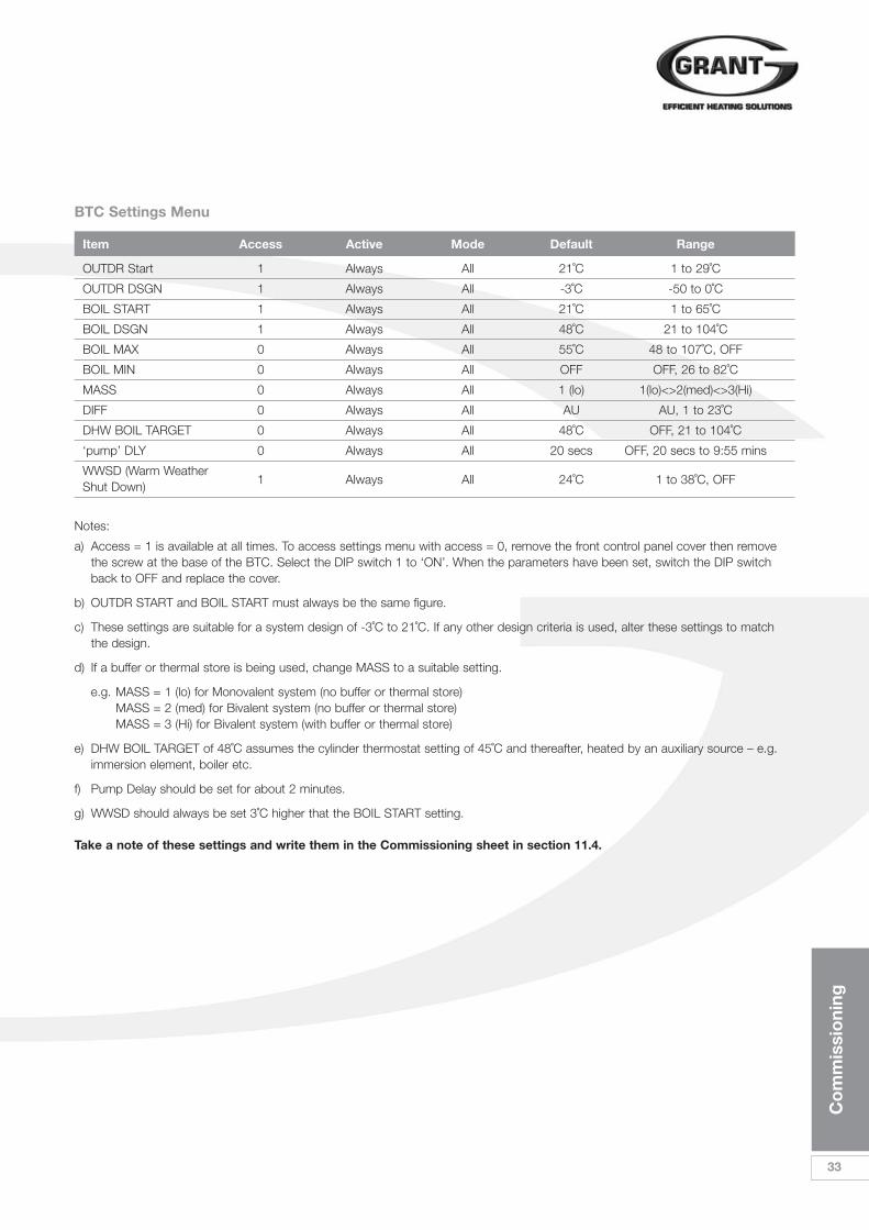
a) Access = 1 is available at all times. To access settings menu with access = 0, remove the front control panel cover then remove the screw at the base of the BTC. Select the DIP switch 1 to ‘ON’. When the parameters have been set, switch the DIP switch back to OFF and replace the cover.
b) OUTDR START and BOIL START must always be the same figure.
c) These settings are suitable for a system design of -3˚C to 21˚C. If any other design criteria is used, alter these settings to match the design.
d) If a buffer or thermal store is being used, change MASS to a suitable setting.
e.g. MASS = 1 (lo) for Monovalent system (no buffer or thermal store)MASS = 2 (med) for Bivalent system (no buffer or thermal store)MASS = 3 (Hi) for Bivalent system (with buffer or thermal store)
e) DHW BOIL TARGET of 48˚C assumes the cylinder thermostat setting of 45˚C and thereafter, heated by an auxiliary source – e.g. immersion element, boiler etc.
f) Pump Delay should be set for about 2 minutes.
g) WWSD should always be set 3˚C higher that the BOIL START setting.
BTC Settings Menu
Item Access Active Mode Default Range
OUTDR Start 1 Always All 21˚C 1 to 29˚C
OUTDR DSGN 1 Always All -3˚C -50 to 0˚C
BOIL START 1 Always All 21˚C 1 to 65˚C
BOIL DSGN 1 Always All 48˚C 21 to 104˚C
BOIL MAX 0 Always All 55˚C 48 to 107˚C, OFF
BOIL MIN 0 Always All OFF OFF, 26 to 82˚C
MASS 0 Always All 1 (lo) 1(lo)<>2(med)<>3(Hi)
DIFF 0 Always All AU AU, 1 to 23˚C
DHW BOIL TARGET 0 Always All 48˚C OFF, 21 to 104˚C
‘pump’ DLY 0 Always All 20 secs OFF, 20 secs to 9:55 mins
WWSD (Warm Weather 1 Always All 24˚C 1 to 38˚C, OFFShut Down)
Take a note of these settings and write them in the Commissioning sheet in section 11.4.

34
Co
mm
issi
oni
ng
ATC
Parameter Description Range Set Value Comments
0 Return water temperature to start electrical heater 0˚C – 30˚C ˚C Do not Adjust
1 Desired Return water temperature setting 10˚C – 60˚C ˚C SET TO 60˚C
2 Defrost cycle 30 Min – 90Min Min Do not Adjust
3 Coil temperature point to start defrosting -30˚C – 0˚C ˚C Do not Adjust
4 Coil temperature point to stop defrosting 2˚C – 30˚C ˚C Do not Adjust
5 Max time for defrosting 1 Min – 12Min Min Do not Adjust
7 Restart after power failure 0/1 1 Do not Adjust0=NO, 1=Yes
9 Water pump working mode 0/1 1 Do not Adjust0 = Cont, 1 = Normal
Fan motor working modeA 0 = daytime working mode 0/1 1 Adjustable
1 = night time working mode
B Target superheat -F – F 3 Do not Adjust
C Manual control paces of EEV 0 – 50 35 Do not Adjust
BTC
Item Access Active Mode Set Value Range
OUTDR Start 1 Always all ˚C 1 to 29˚C
OUTDR DSGN 1 Always All ˚C -50 to 0˚C
BOIL START 1 Always All ˚C 1 to 65˚C
BOIL DSGN 1 Always All ˚C 21 to 104˚C
BOIL MAX 0 Always All ˚C 48 to 107˚C, OFF
BOIL MIN 0 Always All ˚C OFF, 26 to 82˚C
DIFF 0 Always All AU AU, 1 to 23˚C
DHW BOIL TARGET 0 Always All ˚C OFF, 21 to 104˚C
‘pump’ DLY 0 Always All secs OFF, 20 secs to 9:55 mins
WWSD 1 Always All ˚C 1 to 38˚C, OFF(Warm Weather Shut Down)
11 Commissioning
Please complete the following settings:
11.4 Record of ATC and BTC Settings

Ser
vici
ng &
Mai
nten
ance
35
12 Servicing & Maintenance12.1 GeneralGrant Aerona Heat Pumps require onlythe minimum of routine servicing andmaintenance. This basically consists ofa visual check of the unit and should beregularly carried out (e.g. annually) toensure that the heat pump continues tooperate in a safe and efficient manner.
12.2 Air Inlet and OutletThe air inlet grille and evaporator mustbe checked and leaves or any otherdebris removed from the spacebetween the grille and the evaporatorfins.
Ensure that both the air inlet to theevaporator and the discharge from thefan outlet are unobstructed. Any foliage,plants, etc. near the heat pump mustnot be allowed to grow over the unit.
Under no circumstances shouldanything be stacked on or against theunit.
Refer to Section 3.1 for the requiredclearances around the unit.
12.3 Condensate DisposalCheck that condensate drain holes inthe bottom of the unit are not blocked.
12.4 Heating SystemConnectionsCheck the condition of the flexiblehoses. Replace if damaged or leaking.
12.5 Heat Pump ControlsCheck that settings on both the ATCand BTC controllers are as set whencommissioned. Refer to table ofrecorded settings on Page 34 of theseInstructions. Reset to commissionedsettings as necessary.
12.6 RefrigerantUnder no circumstances should therefrigerant be vented from the chargingpoints on the refrigerant circuit of theHeat Pump.
If any work is required to be carried outon the refrigerant circuit, it MUST beundertaken by an F-gas registeredrefrigeration Engineer (or equivalent). On no account should any such workbe carried out by unqualified personnel.
If it is necessary to carry out anyremedial work on the Heat Pump,e.g. replacement of the flexiblehoses, switch the heat pump to off(set the on/off switch on the ATCcontroller to OFF) and isolate theelectrical supply at the externalisolator (and at consumer unit/MCB)BEFORE starting any work on theheat pump or system.
! WARNING
IMPORTANTTake care not todamage or distortthe Aluminium fins ofthe evaporator whenremoving any debris.
36
Faul
t Fi
ndin
g
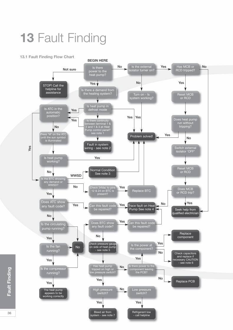
13 Fault Finding
Is there power to the heat pump?
STOP! Call thehelpline forassistance
Is ATC in theautomaticposition?
Is heat pumpworking?
Press ‘M’ on the ATCuntil the sun symbol
is illuminated
Is the BTC showingany demand or
WWSD?Check 24Vac to pins12 & 24 on BTC is
present?
The heat pumpappears to be
working correctly
Check pressure gaugeon side of heat pump
- see note 5
Bleed air from system - see note 7
Refrigerant low - call helpline
Check capacitors and replace if
necessary CAUTION- see note 6
Has heat pumptripped on high or
low pressure switch?
Is there power to thecomponent leaving
the PCB?
Can this fault codebe repaired?
Does BTC showany fault code?
High pressureswitch?
Low pressureswitch?
Trace fault on HeatPump See note 4
Can this fault codebe repaired?
Is the power at the component?
Does ATC showany fault code?
Is the circulatingpump running?
Is the fanrunning?
Is the compressorrunning?
Is there a demand fromthe heating system?
Is heat pump indefrost mode
Fault in systemwiring - see note 2
Normal ConditionSee note 3
Is there continuitybetween terminal 1 &2 and 1 & 3 at Heat
Pump control panel?see note 1
Is the externalisolator turner on?
Turn on - Is system working?
Problem solved!
Reset MCB or RCD
Has MCB or RCD tripped?
Does heat pumprun withouttripping?
Switch externalisolator ‘OFF’
Reset MCB or RCD
Does MCB or RCD trip?
Seek help fromqualified electrician
Replacecomponent
Replace PCB
Replace BTC
No
Yes
Yes
Yes
Yes
Yes
Yes
Yes
Yes Yes
Yes
Yes
Yes Yes
Yes
Yes
Yes Yes
Yes
Yes
Yes
Yes
Yes No
No
No
No
WWSD
No
No
No
No
No
No
No
No
No NoNot sure
BEGIN HERE
Yes
Yes
13.1 Fault Finding Flow Chart

Faul
t Fi
ndin
g
37
13.2 General Notes
1. If no continuity can be foundbetween terminals 1 & 2 and/or 1 & 3 there will be a fault within theheating s-plan system. (see diagramfor location of the terminals.)
2. Please go back to your design ofthe S-plan wiring and check itagainst the installation manual. In detail, trace the demand for CHand DHW in isolation, covering theprogrammer, room or cylinderthermostats, motorised valves andend switches. Make sure that whenthe end switches of the motorisedvalves make, that there is no
voltage present. Voltage on thesewires will do irreparable damage tothe heat pump and will not becovered by the warranty.
3. WWSD (warm weather shut down)happens only under 2 conditions. 1 – when the ambient airtemperature is at 24˚C or equal tothe indoor temperature and 2 –when the CH is the only demand onthe heat pump. WWSD is activewhen WWSD appears on thedisplay of the BTC.
4. MCB’s and RCD can trip for avariety of reasons. Here are somecommon explanations but
remember only qualified electricianscan work on power installations. If you are in any doubt, call anelectrician – not our helpline – wewill only direct you to call anelectrician.
a) Incorrect rating or type ofMCB/RCD
b) A component leaking to earth
c) A component with a dead short
d) Incorrect polarity
e) Incorrect cable size
f) Damaged cable or component
Figure 13-1: Heat pump wiring diagram
230 Vac
CompressorHeater
4-wayvalve
Expansion Valve
DisconnectElectric Elementfor BivalentSwitched Output
For diagram of 6kW immersionheater refer to Figure 8-9.
Ret Gas SensorExt Temp Sensor
Coil Temp SensorDis Gas SensorRet Temp Sensor
N
Compressor
Fanmotor
PumpRelayKM2
3kWElectricElement
Orange
Red
Blu
e
Whi
te
Blk
Power SupplyTerminal
3 Connection points for installer
ATC ControllerSocket S-Plan Controls
Connections
3 2 1 3 2 1
121110987654321
242322212019181716151413C
R S
24 Vac
Fuse
Rel
ay K
M1
Low
pre
ssur
e sw
itch
Hig
h pr
essu
re s
witc
h

Temperature Resistance Temperature Resistance Temperature Resistance Temperature Resistance˚C kW ˚C kW ˚C kW ˚C kW
-20 37.4111 2 13.0055 24 5.1978 46 2.3276
-19 35.5384 3 12.4391 25 5.0000 47 2.2493
-18 33.7705 4 11.9008 26 4.8109 48 2.1740
-17 31.1009 5 11.3890 27 4.6300 49 2.1017
-16 30.5237 6 10.9023 28 4.4569 50 2.0320
-15 29.0333 7 10.4393 29 4.2912 51 1.9651
-14 27.6246 8 9.9987 30 4.1327 52 1.9007
-13 26.2927 9 9.5794 31 3.9808 53 1.8387
-12 25.0330 10 9.1801 32 3.8354 54 1.7790
-11 23.8412 11 8.7999 33 3.6961 55 1.7216
-10 22.7133 12 8.4377 34 3.5626 56 1.6663
-9 21.6456 13 8.0925 35 3.4346 57 1.6131
-8 20.6345 14 7.7635 36 3.3120 58 1.5618
-7 19.6768 15 7.4498 37 3.1943 59 1.5123
-6 18.7693 16 7.1506 38 3.0815 60 1.4647
-5 17.9092 17 6.8652 39 2.9733 61 1.4188
-4 17.0937 18 6.5928 40 2.8694 62 1.3746
-3 16.3203 19 6.3328 41 2.7697 63 1.3319
-2 15.5866 20 6.0846 42 2.6740 64 1.2908
-1 14.8903 21 5.8475 43 2.5821 65 1.2511
0 14.2293 22 5.6210 44 2.4939 66 1.2128
1 13.6017 23 5.4046 45 2.4091
ATC
38
Faul
t Fi
ndin
g
13 Fault Finding5. When tracing a fault code, use the
table of fault codes on page 32 tohelp you. As often as not, it will bea wire that has become loose ordisconnected. Check all wires forsecurity before calling our helplinefor assistance. There are 6 sensorsin total. The ATC have black tailsand the BTC have blue tails. Theresistance/temperature tables forthe ATC and BTC sensors are givenin Figures 13-2 and 13-3.
6. The pressure gauge on the side ofthe heat pump measures refrigerantpressure not water pressure and isa useful tool to help fault finding.
If the heat pump goes out on highpressure, it will almost certainly beas a result of an air-lock. An air-lockthat cannot be cleared by the pumpwill have the same effect as that ofan ordinary boiler. It will overheat as
it cannot get rid of the heat it isproducing. This will be evident if,when switched on from cold orwarm, the gauge rises quicklytowards the yellow or red zones. Ifthis happens, switch off, and purgethe system. (Remember to checkthe circulating pump is working.)
In normal working conditions, thepointer on the gauge will remain inthe green zone.
7. Capacitors store an electricalcharge. Small capacitors are foundin all domestic electronics andcause no danger. However, thecapacitors in a heat pump arepower capacitors and will give alarge electric shock if care is nottaken. DO NOT try to test thefunctionality of a capacitor using ascrewdriver or multi-meter andNEVER try to short out the
connections – even with the mainsvoltage removed. Seek the help of aqualified electrician or a qualifiedheating engineer who has beentrained by Grant Engineering.
8. This is a repeat of note 5. If the heat pump goes out on highpressure, it will almost certainly beas a result of an air-lock. An air-lockthat cannot be cleared by the pumpwill have the same effect as that ofan ordinary boiler. It will overheat asit cannot get rid of the heat it isproducing. This will be evident if,when switched on from cold orwarm, the gauge rises quicklytowards the yellow or red zones. Ifthis happens, switch off, and purgethe system. (Remember to checkthe circulating pump is working.)
Figure 13-2: ATC sensor resistance table

Faul
t Fi
ndin
g
39
Protection/failure Display
Inlet water temperature sensor failure PP 1
Coil temperature sensor failure PP 3
Ambient temperature sensor failure PP 5
Winter anti-freeze protection PP 7
High pressure EE 1
Low pressure EE 2
Flow switch EE 3
Wrong/ miss phase EE 4
Electrical shock protection EE 5
Defrosting Defrosting indicator
communication failure EE 8
Item Field Num Field Display
E01 Err EEprom read error
BOIL OUT SHr HP Flow sensor short
BOIL OUT OPn HP Flow sensor open
BOIL IN SHr HP return sensor short
BOIL IN OPn HP return sensor open
SUP SHr Supply sensor short
SUP OPn EE 3Supply sensor open
OUTDR SHr Outdoor sensor short
OUTDR OPn Outdoor supply sensor open
Figure 13-4: ATC fault codes
Figure 13-3: BTC sensor resistance table
Figure 13-5: BTC fault codes
Temperature Resistance Temperature Resistance Temperature Resistance Temperature Resistance˚C kW ˚C kW ˚C kW ˚C W
-46 490.813 -7 46.218 32 7.334 71 1,689
-43 405.710 -4 39.913 35 6.532 74 1,538
-40 336.606 -1 34.558 38 5.828 77 1,403
-37 280.279 2 29.996 41 5.210 79 1,281
-34 234.196 4 26.099 43 4.665 82 1,172
-32 196.358 7 22.763 46 4.184 85 1,073
-29 165.180 10 19.900 49 3.760 88 983
-26 139.402 13 17.436 52 3.383 91 903
-23 118.018 16 15.311 54 3.050 93 829
-21 100.221 18 13.474 57 2.754 96 763
-18 85.362 21 11.883 60 2.490 99 703
-15 72.918 24 10.501 63 2.255 102 648
-12 62.465 27 9.299 66 2.045 104 598
-9 53.658 29 8.250 68 1.857 107 553
BTC

40
Sp
are
Par
ts L
ist
14 Spare Parts List
Part Number Description HPAW65 HPAW85 HPAW110 HPAW130 HPAW155
HPAS10 Power capacitor 50µF 1 1 0 0 0
HPAS11 Power Capacitor 60µF 0 0 1 1 0
HPAS12 Power Capacitor 70µF 0 0 0 0 1
HPAS13 Power capacitor 100µF 0 0 1 1 1
HPAS14 Fan Capacitor 4µF 1 0 0 0 0
HPAS15 Fan Capacitor 6µF 0 1 1 1 2
HPAS16 Fan Motor A 1 0 0 0 0
HPAS17 Fan Motor B 0 1 1 1 2
HPAS18 PCB 1 1 1 1 1
HPAS19 12Vac Transformer 1 1 1 1 1
HPAS20 24Vac Transformer 1 1 1 1 1
HPAS21 Controller ATC 1 1 1 1 1
HPAS22 Compressor A 1 0 0 0 0
HPAS23 Compressor B 0 1 0 0 0
HPAS24 Compressor C 0 0 1 0 0
HPAS25 Compressor D 0 0 0 1 0
HPAS26 Compressor E 0 0 0 0 1
HPAS27 Controller BTC 1 1 1 1 1
HPAS28 Relay 1 2 2 2 2 2
HPAS29 Circulating Pump A 1 1 1 1 0
HPAS30 Circulating Pump B 0 0 0 0 1
HPAS31 Immersion element 3kW 1 1 1 1 1
HPAS32 Flexible Hoses ¾” 2 2 0 0 0
HPAS33 Flexible Hoses 1” 0 0 2 2 2
HPAS34 Isolation Valves 22mm 2 2 0 0 0
BTC
Relay
Relay
Powercapacitor
12 VacTransformer
24 VacTransformer
PCB
Figure 14-1: Heat pump control panel components

Acc
esso
ries
41
15 Accessories
15.1 Sealed System KitsThese are required when the GrantAerona Heat Pump is used as part ofsealed heating system – refer toSection 7 for further details.
Kit 1 (Grant Ref. HPAW55K12)12 litre expansion vessel kitFor use on heating systems with avolume of up to 110 litres*
Kit contents:12 litre expansion vesselWall bracket and fixing band3 bar pressure relief valveManifoldPressure gaugeFilling loop kit (isolation valve, non-return/isolation valve and filling hose)
Kit 2 (Grant Ref. HPAW55K18) 18 litre expansion vessel kitFor use on heating systems with avolume of up to165 litres*
Kit contents:18 litre expansion vesselWall bracket and fixing band3 bar pressure relief valveManifoldPressure gaugeFilling loop kit (isolation valve, non-return/isolation valve and filling hose)
Kit 3 (Grant Ref. HPAW55K50) 50 litre expansion vessel kitFor use on heating systems with avolume of up to 460 litres*
Kit contents:50 litre expansion vesselWall bracket and fixing band3 bar pressure relief valveManifoldPressure gaugeFilling loop kit (isolation valve, non-return/isolation valve and filling hose)
*maximum system volumes shown forall sealed system kits are based on avessel charge and initial (cold) systempressure of 1 bar.
15.2 Immersion Heater KitsKit 4 (Grant Ref. HPDHWBK1)Automatic domestic hot waterboost kit - with manual overrideThis kit, installed next to the hot watercylinder, allows the stored hot watertemperature to be automaticallyboosted in winter periods using theexisting cylinder immersion element andthermostat. Refer to Section 9 forfurther details.
Kit contents:Double patress c/w relayBlanking plateWater heater switch
Figure 15-1: Sealed system kit Figure 15-2: Automatic hot water boost kit
42
Glo
ssar
y o
f Te
rms
16 Glossary of TermsEfficiencyThe word “efficiency” is defined as theratio of useful heat output to energyinput. For example, if we use 1 kW ofenergy to produce 500W of heat it isdeemed to be 50% efficient.
EntropyLoosely speaking, when a system’senergy is divided into its “useful) energy(energy that can be used, for example,to push a piston), and its “uselessenergy” (that energy which cannot beused to do external work), then entropycan be used to estimate the “useless”,“stray”, or “lost” energy, which dependson the entropy of the system and theabsolute temperature of thesurroundings.
COPThe COP or ‘Coefficient ofPerformance’ is found by dividing theuseful heat output by the energy input.For example; a heat pump thatproduces 4 kW of heat for 1 kW ofinput power has a COP of 4.
SPFSeasonal Performance Factor is similarto COP, but is an average figure takenover the year. It is usually lower thanquoted COP figures due to the need insome cases for additional heat inputduring very cold periods.
SourceThis is wherever the heat is beingextracted from e.g. the outside air orground.
EmittersA term used to describe radiators orunderfloor heating. This is thecomponent that ‘emits’ the heat intothe building.
RefrigerantThe working fluid within the heat pump.It evaporates in one part andcondenses in another. By doing so,heat is transferred from cold to hot.This fluid is sealed in and will notdegrade within the life of the heatpump. Refrigerant handling should onlybe carried out by persons qualified todo so.
Heat ExchangerA component that allows thetransference of heat from one circuit toanother without the two circuits mixing.Two heat exchangers are housed withinthe heat pump, one for the hot side (thecondenser which transfers the heat tothe heating circuit) and one for the coldside (the evaporator).
GeothermalGeothermal is often mistakenly used todescribe a ground source heat pump;proper geothermal energy is where theenergy from the earth’s core is able tomake its way near to the surface,usually using hot water. In the UK thereare only a couple of sites where thistype of energy extraction is feasible as itrequires holes in excess of 2km deep.
Buffer TankThis is simply a large water cylinder thatis used, so we are told, to improve theefficiency and durability of a system. In fact, it reduces the number ofstop/starts the compressor makes.
Heat Pump RatingA heat pump is given a kW heat outputrating. This value will vary depending onthe working temperatures. The electricalpower input will be typically between ahalf and a quarter of the heat output.
MonovalentA monovalent system is one where allof the energy required for the heat loadof the building is available from the heatpump.
BivalentBivalent systems are those whichrequire an additional source to meet thebuildings heat load.

War
rant
y
43
17 Warranty 17.1 The Grant Heat PumpWarrantyDear CustomerYou are now the proud owner of aGrant Aerona Air Source Heat Pumpfrom Grant Engineering (UK) Limited,that has been designed to give years ofreliable, trouble free operation.
Grant Engineering (UK) Ltd. guaranteesthe manufacture of the heat pumpincluding all electrical and mechanicalcomponents for a period of two yearsfrom the date of purchase. Providedthat the card is completed and returnedto Grant UK, the heat pump is installedIn full accordance with the installationinstructions provided and it is servicedafter 12 months operation. (See Termsand Conditions).
ImportantPlease complete the guaranteeregistration section, then detach thecard and return it within 30 days of theinstallation of your Grant Air SourceHeat Pump.
Breakdown during theManufacturer’s WarrantyIf your Grant Heat Pump should failduring the first 2 years, you mustcontact Grant Engineering (UK) Limited,who will arrange for the repair under theterms of their Warranty, providing thatthe system has been correctly installedand commissioned, serviced (if olderthan 12 months) and the fault is notdue to misuse, or the failure of anyexternal components not supplied byGrant UK (e.g. pipework, etc.).
In the first Instance:Contact your installer or commissioningengineer to ensure that the fault doesnot lie with the system or any othercomponents.
If a Fault is Found:Ask your installer to contact GrantEngineering (UK) Limited, ServiceDepartment on 01380 736920 who willarrange for a qualified service engineerto attend to the fault.
Free of Charge Repairs:During the first 2 years no charge forparts or labour will be made providingthat the Heat Pump has been installedand commissioned correctly inaccordance with the manufacturer’sinstructions. Proof of ‘purchase’ datemust be provided upon request.
Chargeable Repairs:A charge will be made if the causeof the breakdown is due to any ofthe following:
• Faults caused by the plumbing or heating system, external electricsand external components.
• The Grant Heat Pump has not been commissioned, or serviced in accordance with the installation and servicing manual.
• The system has been installed forover 2 years.
Remember before you contactGrant:Please complete the guaranteeregistration section, then detach thecard and return it within 30 days of theinstallation of your Grant Heat Pump.
Terms of Manufacturer’s Guarantee1. The Grant Heat Pump guaranteestarts from the date of purchase.
2. All electrical and mechanicalcomponents supplied with the GrantHeat Pump are guaranteed for a periodof two years.
3. The registration card must becompleted and returned within 30 daysof installation. Failure to do so does notaffect your statutory rights.
4. The Grant Heat Pump must beinstalled by a competent installer and inaccordance with the Codes of Practiceand Regulations in force at the time ofthe installation.
5. The Grant Heat Pump and itscomponents must not have beenmodified or tampered with.
6. The installation must be servicedevery 12 months as per the installationinstructions. (Receipts should be keptas proof.)
7. All claims under this guarantee mustbe made to Grant Engineering (UK) Ltdprior to any work being undertaken.Proof of purchase and date ofinstallation must be provided onrequest. Invoices for call out/repair workby any third party will not be acceptedunless previously authorised by GrantEngineering (UK) Ltd.
8. This guarantee is transferableproviding the installation is servicedprior to the dwelling’s new ownerstaking up residence. Grant Engineering(UK) Ltd must be informed of the newowner’s details.
9. Grant Engineering (UK) Ltd willendeavour to provide prompt service inthe unlikely event of a problemoccurring, but cannot be heldresponsible for any consequence ofdelay however caused.
10. This guarantee applies to GrantHeat Pumps installed on the UKmainland, Isle of Man and ChannelIslands only. Provision of in-warrantycover elsewhere in the UK is subject toagreement with Grant Engineering (UK)Ltd.

GRANT ENGINEERING (UK) LTDHopton House, Hopton Industrial Estate, Devizes, Wiltshire. SN10 2EU
Telephone: 01380 736920 Fax: 01380 736991Email: [email protected] Website: www.grantuk.com

To be Completed by the Householder
GRANT ENGINEERING (UK) LTDHopton House, Hopton Industrial Estate, Devizes, Wiltshire. SN10 2EU
Telephone: 01380 736920 Fax: 01380 736991Email: [email protected] Website: www.grantuk.com
Title Initials Surname
Address
Town County Post code
Tel: Home Work Mobile
Heat Pump Model Serial Number
System Type: Monovalent Bivalent
If Bivalent System - other heat source(s):
Gas Boiler Oil Boiler Biomass Boiler Other (specify)
Heating System (tick all that apply):
Radiators only Underfloor only Radiators & Underfloor
Hot Water Cylinder Swimming Pool Heater Thermal Store
Installer Date installed
Address
Town County Post code
Commissioning Engineer (if different) Date Commissioned
Address
Town County Post code
Do you own a:
Grant Oil Boiler? Yes No Grant Solar Thermal System? Yes No
Grant Pellet Boiler? Yes No Grant Solar PV System? Yes No
Grant Hot Water Cylinder? Yes No Grant Thermal Store? Yes No

Guarantee Registration Card
Grant Air Source Heat Pump GuaranteeAir to Water Heat PumpRange
Important - Don’t Delay!
Please complete the attached reply-paid guarantee registration card and return it to:
GRANT ENGINEERING (UK) LIMITEDHopton House, Hopton Industrial Estate, Devizes, Wiltshire SN10 2EUTel: 01380 736920 Fax: 01380 736991Email: [email protected] www.grantuk.com
Guarantee RegistrationGrant Engineering (UK) LimitedHopton HouseHopton Industrial EstateDevizesWiltshireSN10 2EU
• 2 years parts and labourcover on all electrical andmechanical components
•Extended warrantyavailable. Contact Grantfor details.
22BUSINESS REPLY SERVICE
Licence No. SCE15739


