® 106 99-110 Collet-Lok ® product line Swing clamps Linear clamps Power sources Work supports To control and regulate air supply VA-42 Manual operated air valve 5-way, 2-position • For control of boosters • Viton seals standard VAS-42 Solenoid operated air valve 5-way, 2-position • For control of pump and boosters air supply • Viton seals standard • Solenoid: 120 VAC, 50/60Hz Amperage: inrush .11 Amps, holding .07 Amps • Maximum cycle rate: 600 cycles per minute VR-3 Rapid exhaust valve • Enables booster to advance and retract faster • Instantly exhaust air supply from booster to atmosphere V-19 Air check valve • Prevent rapid drop of air pressure to the booster in the event of sudden loss of input air RFL-102 Regulator-Filter-Lubricator • Regulates air pressure • Filter air input • Lubricates air motors with a fine oil vapor mist • Maximum air flow 48 scfm HV-1000A Air pilot holding valve • Holds fluid under pressure offering independent control of different branches of the same fixture • Valve can control the pilot air and the booster in sequence • Max. oil flow 305 in 3 /min • Works with the VA-42 four-way air valve and a booster QE-375 Muffler • Use with VR-3 or VAS/VA-42 • Reduces noise level of exhaust air from pump Air valves Enerpac’s line of directional air valves and accessories complete your workholding system. Used to control air operated hydraulic units, they increase your productivity and efficiency. Application VA-series directional air valves provide either manual or electric control to air operated hydraulic units. Accessories such as rapid exhaust, check valves, silencers and regulators complete the air control system. • Accessory valves provide greater safety and more efficient clamping cycles • Recommended for use with all air powered units • Directional valves to control booster and pump air supply • Remote air valve permits either hand or foot operation Shown: VA-42, VAS-42 Maximum Model pressure number psi t Air valves 30-150 VA-42 30-150 VAS-42 0-100 VR-3 0-100 V-19 t Holding Valve 0-100 HV-1000A* t Accessories 0-125 RFL-102 0-125 QE-375 Product selection * Maximum hydraulic pressure: 3000 psi. Air valves and accessories V, VA, VR, HV, RFL-series Valving help See Basic System Set-up and Valve information in our “Yellow Pages”. Important
Transcript
®106
99-1
10
Col
let-
Lok®
pr
oduc
t lin
eS
win
g cl
amps
Line
ar c
lam
psP
ow
er s
our
ces
Wor
k su
ppor
ts
To control and regulate air supplyVA-42 Manual operated air valve 5-way, 2-position
•Forcontrolofboosters
•Vitonsealsstandard
VAS-42 Solenoid operated air valve 5-way, 2-position
•WorkswiththeVA-42four-way air valve and a booster
QE-375 Muffler
•UsewithVR-3orVAS/VA-42
•Reducesnoiselevelofexhaustairfrompump
Air valvesEnerpac’slineofdirectionalairvalvesandaccessoriescompleteyourworkholdingsystem.Usedtocontrolairoperatedhydraulicunits,theyincreaseyourproductivityandefficiency.
•Accessoryvalvesprovidegreater safety and more efficient clamping cycles
•Recommendedforusewith all air powered units
•Directionalvalvestocontrolbooster and pump air supply
•Remoteairvalvepermitseitherhand or foot operation
Shown:VA-42,VAS-42
Maximum Model pressure number psi
t Air valves
30-150 VA-42
30-150 VAS-42
0-100 VR-3
0-100 V-19
t Holding Valve
0-100 HV-1000A*
t Accessories
0-125 RFL-102
0-125 QE-375
Product selection
*Maximumhydraulicpressure:3000psi.
Air valves and accessories V, VA, VR, HV, RFL-series
Valving helpSee Basic System Set-up
and Valve information in our “Yellow Pages”.
Important
www.enerpacwh.com ® 107
141 A
142 A190 ▸
192 ▸
194 ▸
197 ▸
P
A
AP
1/4"-18NPT
VAS-42 QE-375V-19
VR-3
HV-1000A
RFL-102 VA-42
Po
wer S
ources
Pallet C
omponents
ValvesS
ystem C
omponents
Yellow pages
Options
Air Pressure: 0-150 psi
E Válvulas de aire
F Valves à air
D Luftventile
Gauges and adaptors
Hoses
Fittings
Valving helpSee Basic System Set-up
and Valve information in our “Yellow Pages”.
Important
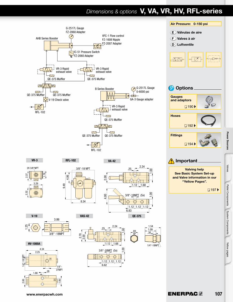
AHB Series Booster
B Series Booster
G-2517L Gauge FZ-2060 Adapter
G-2517L Gauge 0-6000 psi
IC-51 Pressure Switch FZ-2060 Adapter
QE-375 Muffler QE-375 Muffler
V-19 Check valve
RFL-102
RFL-102
VR-3 Rapid exhaust valve
VR-3 Rapid exhaust valve
VR-3 Rapid exhaust valve
QE-375 Muffler QE-375 Muffler
QE-375 Muffler
QE-375 MufflerQE-375 Muffler
GA-3 Gauge adapter
VFC-1 Flow controlFZ-1608 Nipple FZ-2007 Adapter
Dimensions & options V, VA, VR, HV, RFL-series
1.541.09.69 .30
2.37 1.78
2.32
3.29
2X 3/8"NPT
8.34
3/8"-18 NPT
4.06
9.49
3/8" -18NPT
3.86
1.25
1.12
4.00
1.12 1.12
1.681.12
.252.24
3/8"-18NPT (5x)
2.00
1.00
1.00
6.83
1.12 1.12 1.12
1.681.12
.252.24
3/8"-18NPT (5x)
2.002.70
1.00
1.00
6.62
.281.88
1/8"-27NPT
2.254.34
1.00
2.00
1/4"
-18
NPT
www.enerpac.com
▼
110
A
P T
A
P T
B
A
P T
B
A
P T
B
A
P T
B
A B
P T
A
PB
PA
P T
B
A
P TA
P T
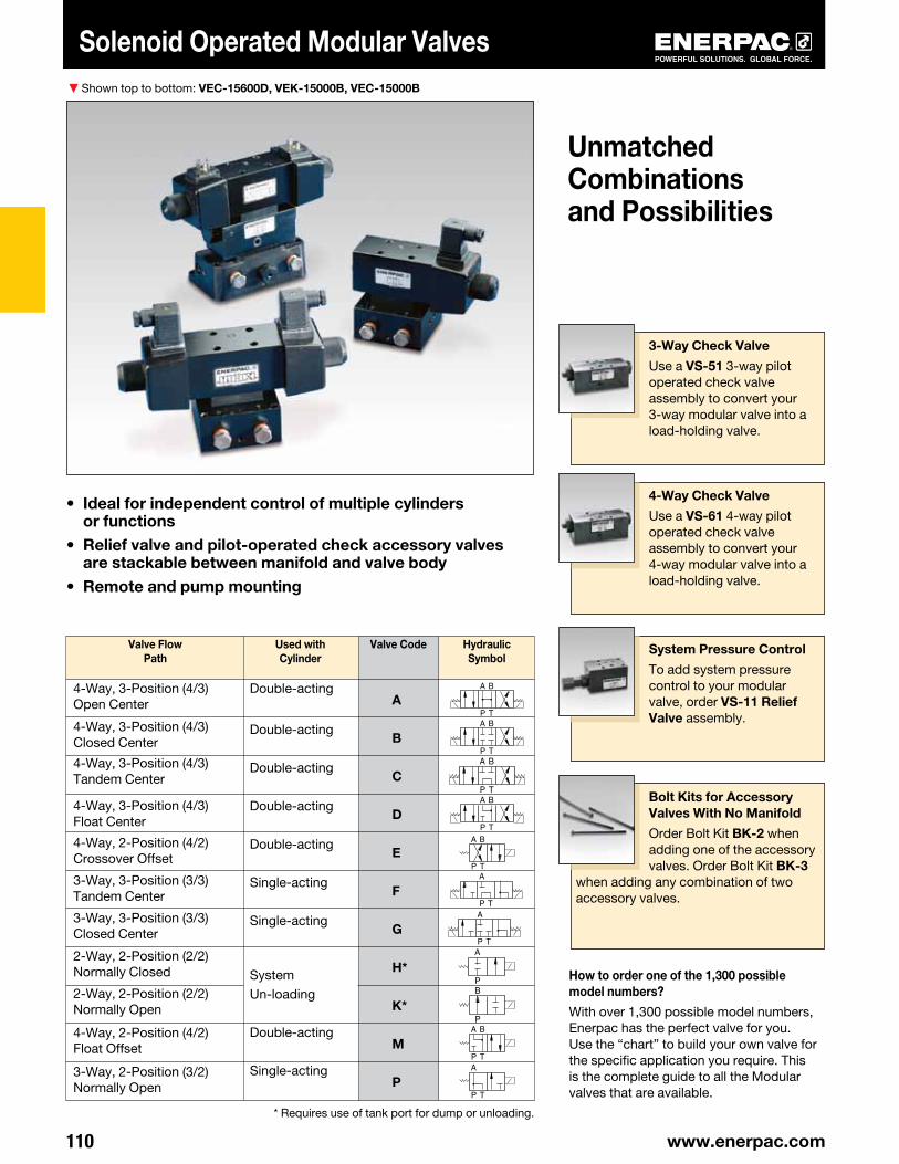
Solenoid Operated Modular Valves
3-Way Check Valve
Use a VS-51 3-way pilot ope ra ted check valve assembly to convert your 3-way modular valve into a load-holding valve.
4-Way Check Valve
Use a VS-61 4-way pilot ope ra ted check valve assembly to convert your 4-way modular valve into a load-holding valve.
System Pressure Control
To add system pressure control to your modular valve, order VS-11 Relief Valve assembly.
Bolt Kits for Accessory Valves With No Manifold
Order Bolt Kit BK-2 when adding one of the accessory valves. Order Bolt Kit BK-3
when adding any combination of two accessory valves.
• Ideal for independent control of multiple cylinders or functions
• Relief valve and pilot-operated check accessory valves are stackable between manifold and valve body
• Remote and pump mounting
How to order one of the 1,300 possible model numbers?
With over 1,300 possible model numbers, Enerpac has the perfect valve for you.Use the “chart” to build your own valve for the specific application you require. This is the complete guide to all the Modular valves that are available.
4-Way, 3-Position (4/3) Open Center
4-Way, 3-Position (4/3)Closed Center
4-Way, 3-Position (4/3)Tandem Center
4-Way, 3-Position (4/3)Float Center
4-Way, 2-Position (4/2)Crossover Offset
3-Way, 3-Position (3/3)Tandem Center
3-Way, 3-Position (3/3)Closed Center
2-Way, 2-Position (2/2)Normally Closed
2-Way, 2-Position (2/2)Normally Open
4-Way, 2-Position (4/2)Float Offset
3-Way, 2-Position (3/2)Normally Open
Double-acting
Double-acting
Double-acting
Double-acting
Double-acting
Single-acting
Single-acting
System Un-loading
Double-acting
Single-acting
A
B
C
D
E
F
G
H*
K*
M
P
Valve Flow Path
Used with Cylinder
Valve Code Hydraulic Symbol
Shown top to bottom: VEC-15600D, VEK-15000B, VEC-15000B
Unmatched Combinations and Possibilities
* Requires use of tank port for dump or unloading.
111®
6001 5 DAVE - -
A
B
T
P
1/4"-18NPTF
3/8"-18NPTF (2x)
3/8"-18NPTF
Pressure Drop versus Oil Flow
Solenoid Operated Modular Valves
VE Series
Flow Capacity:
4 gal/min.Maximum Operating Pressure:
10,000 psi
1Solenoid Operated
Valve
2Valve Flow Path
3Flow
Capacity
4Voltage
5Accessory
Valves
6Manifold
1 Product Type VE = Solenoid Operated Valve
2 Valve Code A = 4/3 Open Center B = 4/3 Closed Center C = 4/3 Tandem Center D = 4/3 Float Center E = 4/2 Crossover Offset F = 3/3 Tandem Center G = 3/3 Closed Center H = 2/2 Normally Closed K = 2/2 Normally Open M = 4/2 Float Offset P = 3/2 Normally Open
5 Accessory Valves 000 = No accessory valves 100 = Relief Valve only 150 = Relief Valve and 3-way pilot
operated check valve Only for VEF/VEG 160 = Relief Valve and 4-way pilot
operated check valve Only for VEA/VEB/VEC/VED
500 = 3-way pilot operated check valve
Only for VEF/VEG 600 = 4-way pilot operated
check valve Only for VEA/VEB/VEC/VED
6 Manifold A = No manifold** B = Remote Mounted D = Pump Mounted*
* Only for valve code: VEA/VEC/VEF** Must order Bolt Kit separately.
CUSTOM BUILD YOUR MODULAR VALVES
▼ This is how a Modular Valve Model Number is built up:
Example: VEA-15600-D
VEA-15600-D is a Modular Valve with a 4-way, 3-position open center flowpath, 115 VAC, and an integral pilot-operated check valve, for mounting on an Enerpac pump.
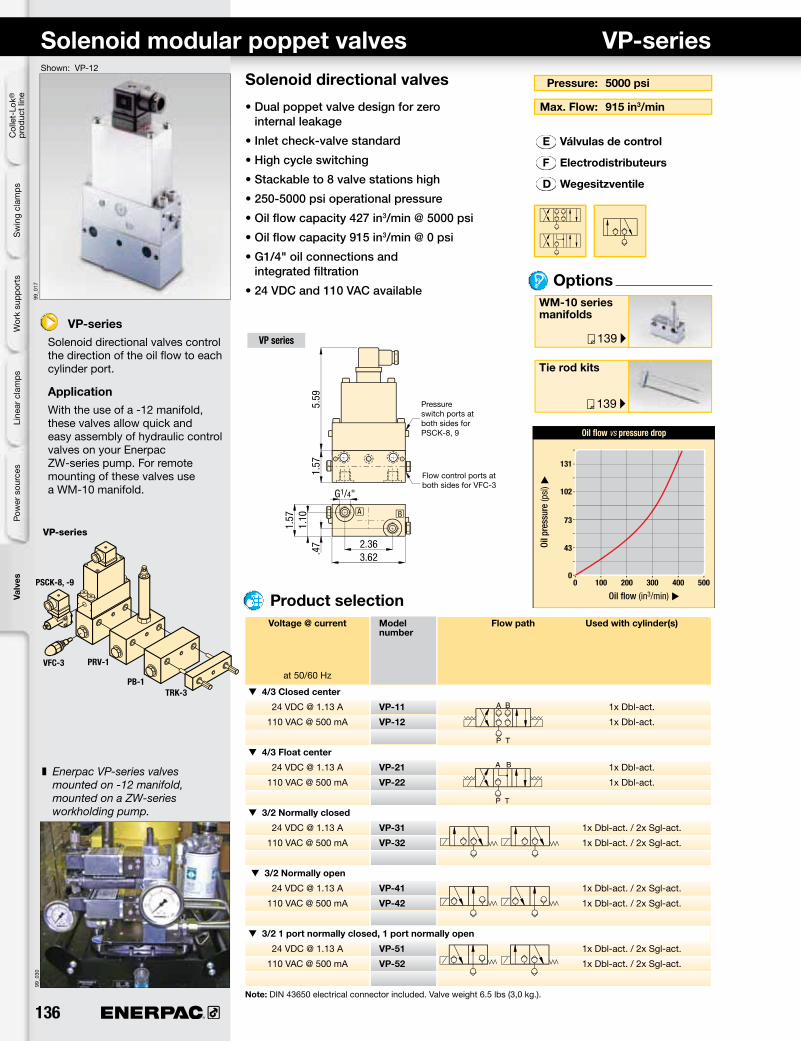
• Dual poppet valve design for zero internal leakage
• Inlet check-valve standard
• High cycle switching
• Stackable to 8 valve stations high
• 250-5000 psi operational pressure
• Oil flow capacity 427 in3/min @ 5000 psi
• Oil flow capacity 915 in3/min @ 0 psi
• G1/4" oil connections and integrated filtration
• 24 VDC and 110 VAC available
VP-seriesSolenoid directional valves control the direction of the oil flow to each cylinder port.
ApplicationWith the use of a -12 manifold, these valves allow quick and easy assembly of hydraulic control valves on your Enerpac ZW-series pump. For remote mounting of these valves use a WM-10 manifold.
z Enerpac VP-series valves mounted on -12 manifold, mounted on a ZW-series workholding pump.
Options
Pressure: 5000 psi
Max. Flow: 915 in3/min
WM-10 series manifolds
Tie rod kits
E Válvulas de control
F Electrodistributeurs
D Wegesitzventile
VP series
Pressure switch ports at both sides for PSCK-8, 9
Flow control ports at both sides for VFC-3
Product selection Voltage @ current Model Flow path Used with cylinder(s) number
at 50/60 Hz
t 4/3 Closed center
24 VDC @ 1.13 A VP-11 1x Dbl-act.
110 VAC @ 500 mA VP-12 1x Dbl-act.
t 4/3 Float center
24 VDC @ 1.13 A VP-21 1x Dbl-act.
110 VAC @ 500 mA VP-22 1x Dbl-act.
t 3/2 Normally closed
24 VDC @ 1.13 A VP-31 1x Dbl-act. / 2x Sgl-act.
110 VAC @ 500 mA VP-32 1x Dbl-act. / 2x Sgl-act.
t 3/2 Normally open
24 VDC @ 1.13 A VP-41 1x Dbl-act. / 2x Sgl-act.
110 VAC @ 500 mA VP-42 1x Dbl-act. / 2x Sgl-act.
t 3/2 1 port normally closed, 1 port normally open
PSCK, VFC-series Pressure switches, Flow control valveShown: PSCK-8, VFC-3
PSCK-8, 9
Adjustable pressure switches will open or close electrical contacts when the desired pressure value is reached.
Application
To open or close an electric circuit when a preset pressure value is reached. The electrical circuit is used to control further working cycles, such as actuating control valves or to terminate a working cycle. Directly mounted into Enerpac VP-series valves.
To control your hydraulic system
• Mounts directly into VP-series modular valves
• In-line installation
• Cartridge type flow control valve and pressure switches can be manifold mounted for remote use
• Lockable adjustment screw on PSCK models
PSCK-8, 9 PSCK-8, 9 mounting dimensions
VFC-3
Screw-in throttle type valve to control the amount of oil flow to the hydraulic cylinder.
Application
Used to control cylinder speed in hydraulic circuits. Directly mounted into Enerpac VP-series valves or custom made manifolds for remote applications.
VFC-3 VFC-3 mounting dimensions
Hydraulic connection
Protective cover
Hex. Lock nut
Hex. Adjustment screw
z PSCK-8 and VFC-3 directly mounted on VP-valves.
Solenoid Model Hydraulic Pressure Deadband Maximum voltage @ current number scheme range oil flow
at 50/60 Hz psi psi in3/min
t Pressure switch
24 VDC @ 2 A
115 VAC @ 2 A PSCK-8
1450 - 5000 261 - 501 427
t Pressure switch
24 VDC @ 2 A
115 VAC @ 2 A PSCK-9
290 - 3045 87 - 218 427
t Flow control valve
screw-in
throttle VFC-3 0-5000 – 427
valve
Product selection
E Presostatos
F Pressostats
D Druckschalter
29
58
87
116
122 1830
Oil flow (in3/min) u
VFC-3 Back pressure vs flow return
Back
pre
ssur
e (p
si) u
24 305 6100
145
Flow direction B-A
1.26.51
.157
M8x1
ø.197-.200
max
. ø.2
0.5
9
.04
.55
.71-
.75
min
. .98
M8x1
ø.39-.40ø.67-.70
118°
32.002 C
138 ®
99-0
2499
-021
PA
188 ▸
139 ▸
136 ▸
PRV-1, PRV-5
X X
R
G2517L
VFC3
VFC3
WM-10
TRK-2
P
Col
let-
Lok®
pr
oduc
t lin
eS
win
g cl
amps
Line
ar c
lam
psPo
wer
sou
rces
Valv
esW
ork
supp
orts
Mounting Adjustable Maximum Model Oil Maximum style pressure pressure number ports oil flow range
psi psi BSPP in3/min lbs
VP-series 435 - 4350 5000 PRV-1 G1/4" 427 3.5
VP-series 75 - 2000 5000 PRV-5 G1/4" 427 3.5
Product selection
Pressure reducing valves PRV-series
Precise control of hydraulic pressure
• Stackbuilding with VP series modular valves
• Stackable for multiple pressures on one valve stack assembly
• Tool adjustable knob can be locked
• Precise control of pressure
PRV seriesThese valves regulates system pressure for all subsequent valves, according to the adjusted pressure. Maintains a constant pressure in a secondary circuit. Includes a check valve that prevents pressure drop on secondary side.
ApplicationUsed when a hydraulic supply with a higher pressure (primary side) must also be used for another circuit with a lower pressure (secondary circuit). PRV-1 can be stack built between VP-series valves.
z PRV-1 connected with remote manifold WM-10.
Shown: PRV-1
Options
Pressure: 5000 psi
Flow: 417 in3/min
VP-Modular valves
Pressure switches
E Válv. reguladora de presión
F Valve de pression réglable
D Druckreduzierventil
Tie rod kits
Valve stacking example
Gauge Port
PRV-1 Pressure Reducing Valve
VP-21 (24 VDC) or VP-22 (115 VAC)
1.57 .4
7
7.60
1.57
3.62
1.34
G1/4"
www.enerpacwh.com 139®
99-0
0599
_035
P T
130 ▸
PM5
M3
M4
M6A
PR
A B
A B
P T
PM5
M3
M4
188 ▸
189 ▸PB-1
TRK
WM-10
Pallet com
ponentsValves
System
components
Yellow pages
TRK, WM/PB-series Tie rod kits, Remote/porting manifolds
Simplifies valve and accessory mountingTRK-series tie rods
• Connects 1 to 8 VP-series valves station high• Provide leak-free sealing valves• G1/4" oil connection
• Provide 3 auxiliary pressure lines• G1/4" oil connection
Shown: WM-10, TRK-4, PB-1
Options TRK-series
Tie Rod Kits mount Enerpac VP-series modular valves to the WM-10 manifold and can accommodate one to eight VP-valve stations.
PB-1
Porting manifold provides three pressure ports for auxiliary lines or accessories, such as a pressure gauge. Mounts between VP-series modular valve stations using TRK-series tie rod kits.
WM-10
Remote manifold allows mounting of VP-series modular valves to a remote location from the pumping unit. This manifold has a built-in adjustable relief valve.
Pressure: 5000 psi max.
Flow: 915 in3/min
VP-series directional valves
E Pernos de montaje de válv.
F Vis de montage de distrib.
D Zugstangen
Mounting: 1-8 VP valve stations
VP-series
z Tie rods mount VP-series valves and accessories to manifold, providing leak-free sealing.
Quantity Model Tie rod Mounting of stackable number length thread VP-series A directional valves inch mm
t Tie rod kits
1 TRK-1 3.45 M6
2 TRK-2 4.92 M6
3 TRK-3 6.50 M6
4 TRK-4 8.07 M6
5 TRK-5 9.65 M6
6 TRK-6 11.22 M6
7 TRK-7 12.80 M6
8 TRK-8 14.37 M6
Product selection Product selection Oil Model Hydraulic Maximum ports number schematic pressure
BSPP psi
t Remote manifold with pressure relief
2x G1/4" WM-10 5000
t Porting manifold (P port connection)
3x G1/4" PB-1 5000
Cap nutSeal washer
Mounting for PSCK-8, 9
Tie rod
Endplate
Adjustable Relief valve
Pressure switches
Gauges
G1/4"(2x)2.17
1.57
.38
.98
.71
M8
.55
M6
1.813.62
1.57
2.85
G1/4"(3x)
1.343.62
1.57
.47
1.57
140 ®
A B
P T
144 ▸
194 ▸
A B
P T
99_1
1199
_121
ABP TG
ABP T
A B
A B
A B
P T
A B
P T
ABP TG
ABP T
VSS
VD1PVST
VAS/VAT
PT
Col
let-
Lok®
pr
oduc
t lin
eS
win
g cl
amps
Line
ar c
lam
psPo
wer
sou
rces
Valv
esW
ork
supp
orts
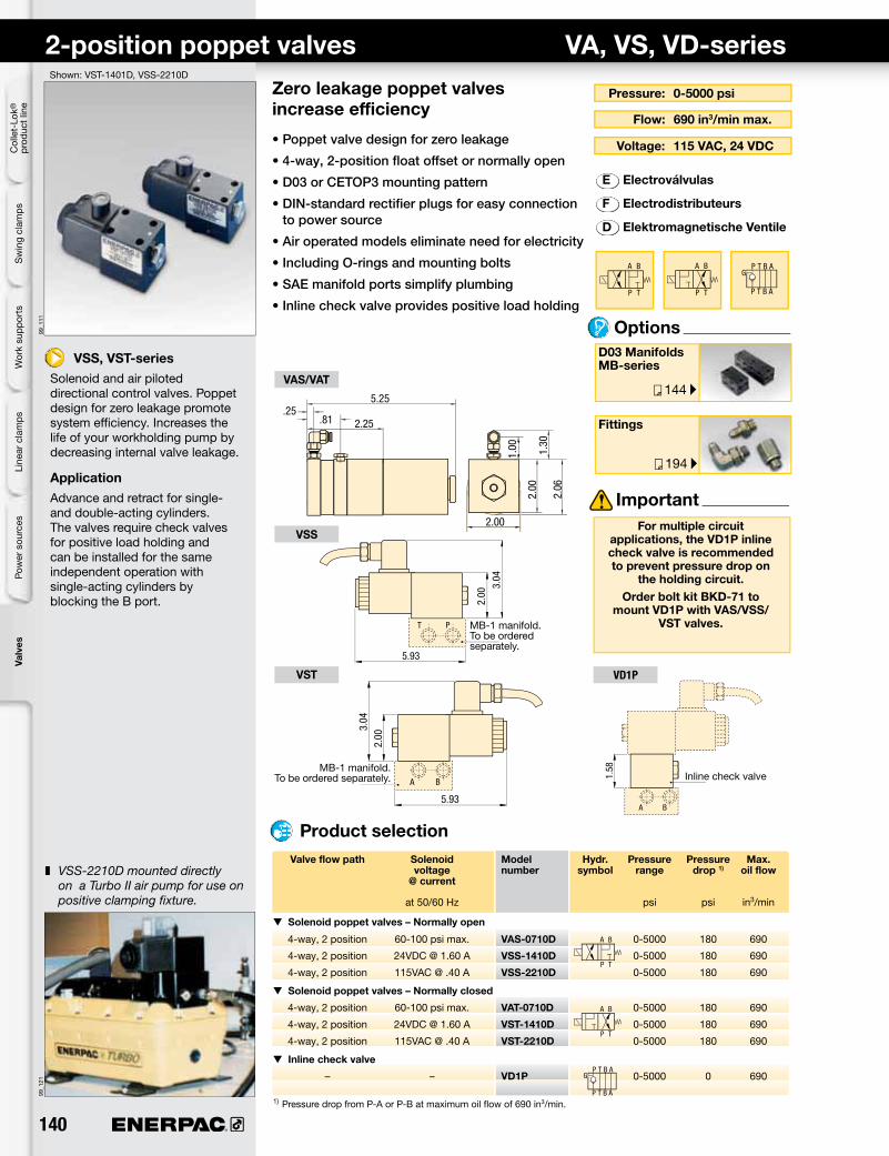
Zero leakage poppet valves increase efficiency
• Poppet valve design for zero leakage
• 4-way, 2-position float offset or normally open
• D03 or CETOP3 mounting pattern
• DIN-standard rectifier plugs for easy connection to power source
• Air operated models eliminate need for electricity
VSS, VST-seriesSolenoid and air piloted directional control valves. Poppet design for zero leakage promote system efficiency. Increases the life of your workholding pump by decreasing internal valve leakage.
ApplicationAdvance and retract for single- and double-acting cylinders. The valves require check valves for positive load holding and can be installed for the same independent operation with single-acting cylinders by blocking the B port.
Options
Flow: 690 in3/min max.
Voltage: 115 VAC, 24 VDC
D03 Manifolds MB-series
Fittings
E Electroválvulas
F Electrodistributeurs
D Elektromagnetische Ventile
Product selection
Pressure: 0-5000 psi
z VSS-2210D mounted directly on a Turbo II air pump for use on positive clamping fixture.
Shown: VST-1401D, VSS-2210D
MB-1 manifold. To be ordered separately.
MB-1 manifold. To be ordered separately.
Important For multiple circuit
applications, the VD1P inline check valve is recommended to prevent pressure drop on
the holding circuit.Order bolt kit BKD-71 to
mount VD1P with VAS/VSS/VST valves.
Inline check valve
2-position poppet valves VA, VS, VD-series
Valve flow path Solenoid Model Hydr. Pressure Pressure Max. voltage number symbol range drop 1) oil flow @ current at 50/60 Hz psi psi in3/min
t Solenoid poppet valves – Normally open
4-way, 2 position 60-100 psi max. VAS-0710D 0-5000 180 690
4-way, 2 position 24VDC @ 1.60 A VSS-1410D 0-5000 180 690
4-way, 2 position 115VAC @ .40 A VSS-2210D 0-5000 180 690
t Solenoid poppet valves – Normally closed
4-way, 2 position 60-100 psi max. VAT-0710D 0-5000 180 690
4-way, 2 position 24VDC @ 1.60 A VST-1410D 0-5000 180 690
4-way, 2 position 115VAC @ .40 A VST-2210D 0-5000 180 690
t Inline check valve
– – VD1P 0-5000 0 690
1) Pressure drop from P-A or P-B at maximum oil flow of 690 in3/min.
.25.81 2.25
5.25
2.00
1.30
1.00
2.00
2.06
5.93
2.00
3.04
5.93
2.00
3.04
1.58
www.enerpacwh.com 141®
194 ▸
144 ▸
A P T B
A P T B
VPO3-11, 12, 21, 22 VPO3-51, 52
VFC-4 PRV-6, PRV-7VD2P
A B
P T
A B
P T
Pallet com
ponentsValves
System
components
Yellow pages
VP03-series Solenoid poppet valves
Pressure: 0-5000 psi
Flow: 3-15 gpm
Fittings
E Electrovávulas
F Electrodistributeurs
D Elektromagnetische Ventile
VP03 series valves are zero leakage and can be used with pressure shut down
electric pumps and air driven Turbo II pumps.
Important
Options
Product selection Valve flow path Solenoid Model Hydraulic Pressure Maximum voltage number symbol range oil 50/60 hz flow
psi gpm
3-position/4 way, 24 VDC VP03-11 0-5000 5
Closed center 110 VAC VP03-12 0-5000 5
3-position/4 way, 24 VDC VP03-21 0-5000 5
Float center 110 VAC VP03-22 0-5000 5
2-position/4 way 24 VDC VP03-51 0-3626 4
110 VAC VP03-52 0-3626 4
Dual flow control – VFC-4 0-5000 10
Dual pilot operated – VD2P 0-5000 15 check valve
Pressure reducing valve – PRV-6 435-4350 3.2
– PRV-7 75-2000 1.6
VP03 Directional Valves and accessories
• D03/CETOP 3 mounting pattern
• Directional valves
• Pilot operated check valve
• Dual flow control
• Pressure reducing valve
VP03-seriesVP03 valves are zero leakage, solenoid operated poppet valves.
ApplicationUsed to control the advance and retract of single acting and double acting cylinders.
Voltage: 24 VDC, 110 VAC
Shown: VP03
z VP03-11 valve on PASG-3002SB Turbo pump.
Spacer
Pin
Closed
Open
D03 ManifoldsMB-series
1.58
1.58
3.011.58 1.37
3.011.58 1.37
.96
1.18.33
8.00
3.63
2.02
1.77
1.67
2.250.05
0.64
0.47
4.88
142 ®
194 ▸
144 ▸
99_1
11
A P T B
A P T B
T
B
P
A
TP
BA
BA
PP
VFC-4
VEW-11
VET-11, VEX-11
PRV-6, PRV-7VD2P
Col
let-
Lok®
pr
oduc
t lin
eS
win
g cl
amps
Line
ar c
lam
psPo
wer
sou
rces
Valv
esW
ork
supp
orts
Solenoid spool valves, D03/CETOP3 VE-series
Pressure: 0-5000 psi
Flow: 3-15 gpm
Fittings
E Electrovávulas
F Electrodistributeurs
D Elektromagnetische Ventile
D03 ManifoldsMB-series
To hold the pressure in a clamping circuit, use the
VEX11 valve with the VD2P check module. Do not use D03
spool valves with pressure shutdown pumps.
Important
Options
Product selection Valve flow path Solenoid Model Hydraulic Pressure Pressure Maximum voltage number symbol range drop oil flow 50/60 hz psi psi gpm
2-position/4 way 24 VDC VEW-11 0-5000 125 8
1.32 Amps
3-position/4 way, 24 VDC VET-11 0-5000 150 8
Closed center 1.32 Amps
3-position/4 way, 24 VDC VEX-11 0-5000 165 8
Float center 1.32 Amps
Dual flow control – VFC-4 0-5000 – 10
Dual pilot operated – VD2P 0-5000 200 15
check valve
Pressure reducing valve – PRV-6 / 435-4350
PRV-7 75-2000 – 3
D03 Direction Valve and accessories
• D03 mounting pattern
• Directional valves
• Pilot operated check valve
• Dual flow control
• Pressure reducing valve
VE-seriesSpool style solenoid valves and control modules are used in circuits that do not require zero leakage.
ApplicationUsed to control the advance and retract of single acting and double acting cylinders. The dual check valve can be used to lock pressure in a group of cylinders. The dual flow control offers independent control of cylinder advance and retract speeds. The pressure reducing valve sets a circuit pressure lower than the main pump pressure.
Voltage: 24 VDC
Spacer
Pin
Closed
Open
Shown: VEX-11 valve
z VEX-11 valve on ZW5020HG-FT21 pump.
3.64
1.97
6.253.02
4.59
3.64
1.97
9.473.23 3.02
4.59
3.63
2.02
1.771.
67
2.250.05
0.64
0.47
4.88
1.18.33
8.00
www.enerpacwh.com 143®
A B
P T
144 ▸
A
P T
B
99_1
02
192 ▸
194 ▸
◂ 140
99_1
22a
A B
P TA
P T
B
VMTD-001, 003 VMMD-001, -003
Pallet com
ponentsValves
System
components
Yellow pages
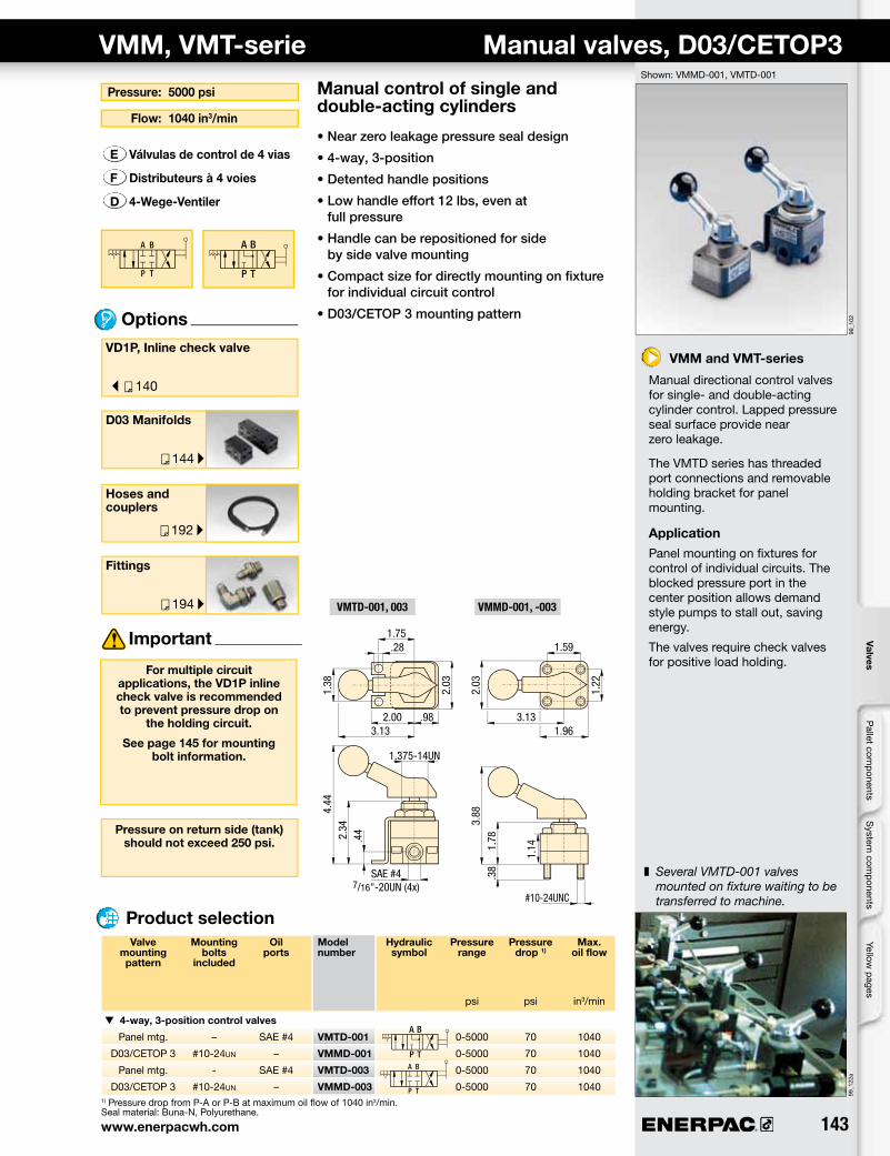
Pressure: 5000 psi
Flow: 1040 in3/min
D03 Manifolds
Options
E Válvulas de control de 4 vias
F Distributeurs à 4 voies
D 4-Wege-Ventiler
VMM, VMT-serie Manual valves, D03/CETOP3
VMM and VMT-series
Manual directional control valves for single- and double-acting cylinder control. Lapped pressure seal surface provide near zero leakage.
The VMTD series has threaded port connections and removable holding bracket for panel mounting.
ApplicationPanel mounting on fixtures for control of individual circuits. The blocked pressure port in the center position allows demand style pumps to stall out, saving energy.
The valves require check valves for positive load holding.
Manual control of single and double-acting cylinders
• Near zero leakage pressure seal design
• 4-way, 3-position
• Detented handle positions
• Low handle effort 12 lbs, even at full pressure
• Handle can be repositioned for side by side valve mounting
• Compact size for directly mounting on fixture for individual circuit control
• D03/CETOP 3 mounting pattern
z Several VMTD-001 valves mounted on fixture waiting to be transferred to machine.
Valve Mounting Oil Model Hydraulic Pressure Pressure Max. mounting bolts ports number symbol range drop 1) oil flow pattern included
psi psi in3/min
t 4-way, 3-position control valves
Panel mtg. – SAE #4 VMTD-001 0-5000 70 1040
D03/CETOP 3 #10-24un – VMMD-001 0-5000 70 1040
Panel mtg. - SAE #4 VMTD-003 0-5000 70 1040
D03/CETOP 3 #10-24un – VMMD-003 0-5000 70 1040
Product selection
1) Pressure drop from P-A or P-B at maximum oil flow of 1040 in3/min.Seal material: Buna-N, Polyurethane.
Fittings
Hoses and couplers
VD1P, Inline check valve
For multiple circuit applications, the VD1P inline check valve is recommended to prevent pressure drop on
the holding circuit.
See page 145 for mounting bolt information.
Important
Pressure on return side (tank) should not exceed 250 psi.
Shown: VMMD-001, VMTD-001
1.22
2.03
3.131.96
#10-24UNC
1.59
1.78
1.14
.38
3.88
2.03
2.00 .98
1.375-14UN
3.13
.281.75
1.38
2.34
.44
4.44
SAE #47/16"-20UN (4x)
144 ®
188 ▸
P
BA
P
TTBA
190 ▸
194 ▸
140 ▸
99_1
01
AP T
BBA
P
T
G
G G
T
B
A
B
A
B
A
B
A
P
L
.312-18 UNC
MB-2, -4
MB-1
Col
let-
Lok®
pr
oduc
t lin
eS
win
g cl
amps
Line
ar c
lam
psPo
wer
sou
rces
Valv
esW
ork
supp
orts
Valve manifolds MB-series
Mounting: 1-4 valves
Pressure: 5000 psi max.
Pressure switches
E Colectores
F Manifolds
D Verkettungsblöcke
When independent control of multiple cylinders is required
• Multi-station manifolds with SAE or CETOP 3 porting – minimizes plumbing
• Mounting patterns for: VSS/VST Valves (D03 or CETOP 3); VE Valves (D03 or CETOP 3); VP03 Valves (D03 or CETOP 3); VMMD Valves (D03 or CETOP 3)
• Manifolds allow use of accessories, such as pressure switches and gauges
Product selection
Fittings
VSS, VST- series valves
Use MC-1 (D03) / MC-3 (CETOP 3) cover plates to seal non-used manifold stations.
Use MC-1 / MC-3 cover plates to seal unused
manifold stations.
Important Important
Valve mounting pattern Number Model Oil ports Coverplate Manifold of valve number cover plate model stations number* G L
in lbs
t Single station manifold
D03 1 MB-1 SAE #4 – – 1.0
CETOP 3 1 MB-12 G1/4" – – 1.0
t Multiple station manifolds
D03 2 MB-2 SAE #8 MC-1 4.75 3.3
CETOP 3 2 MB-22 G3/8" MC-3 4.75 3.3
D03 4 MB-4 SAE #8 MC-1 8.75 6.1
CETOP 3 4 MB-42 G3/8" MC-3 8.75 6.1
Options
Valve mounting pattern
Standard mounting hole for .312 Socket Head Cap Screw
*Note: - MC-1 manifold cover plate must be ordered separately. Includes gasket and mounting bolts.
MB-series
Single or multiple station manifolds allow installation of VSS and VST-series positive seal control valves or other D03/CETOP 3 valves. Ideal in applications where independent control of multiple cylinders is required.
Shown: MB-4, MB-1
z Each non-used valve station on manifolds must be sealed with MC-1 cover plate.
Gauges and accessories
2.50 1.50.34 1.00
3.00
.43
1.93
3.50
3.00
1.00
3.07 1.
57
2.15
.65
.31 2.00 1.382.19
2.06
2.75
.632.13
2.75
1.35
.28
1.38
4.00 .38
148 ®
99-1
38
A
P T
A
P T
A
P T
A
P T
A
P T
99-1
23
Col
let-
Lok®
pr
oduc
t lin
eS
win
g cl
amps
Line
ar c
lam
psPo
wer
sou
rces
Valv
esW
ork
supp
orts
Reliable control of single-acting cylinders
• Directional control valves provide advance/hold/retract operation for use with single-acting cylinders
• Remote or pump mounting on most Enerpac pumps
• Return line kit included with remote valves
• Available “locking” option on VC and VM-series valves for load-holding applications
V-seriesManual operated 3-way, 2-position and 3-way, 3-position directional control valves for operation of single-acting cylinders. Remote mount valves include return line kit for connecting the valves to pump reservoir.
ApplicationPump mounted valves provide centralized control of pump output for cylinder cycling. Remote mounted at any convenient point along the system where control of cylinders is needed.
Shown: VM-2, VM-3
3-way directional manual control valves Application & selection
Select the required center position
z Four VC-15 Enerpac manual valves mounted on fixture to give independent control of several hydraulic circuits.
Non-locking
• Use in simple clamping circuits. Has interflow between ports when shifted.
Closed center
• For multiple valve and cylinder operation. All ports blocked in the center position.
Locking center
• For positive load holding without loss of pressure. Cylinder travel can only resume by shifting valve from hold position.
Tandem center
• For one or multiple cylinder operation. Pump flow is directed back to tank in the center position.
Valve type Valve Model Hydraulic mounting number symbol location
t Manual 3-way, 2-position (3/2)
– Pump VM-2
t Manual 3-way, 3-position (3/3)
Tandem center Pump VM-3
Tandem center Remote VC-3
t Manual 3-way, 3-position (3/3)
Tandem center, Pump VM-3L
locking
Tandem center, Remote VC-3L
locking
Closed center Remote VC-15
Closed center, Remote VC-15L locking
Product selection
www.enerpacwh.com 149®
A
P T
A
P T
190 ▸
192 ▸
194 ▸
197 ▸
P
A
P T
A
P
A
P T
A
P T
A
P T
A
P
A
P
A
P T
A
P
A
VM-2
VM-3, VM-3L VC-3, VC-3LVC-15, VC-15L
Pallet com
ponentsValves
System
components
Yellow pages
Dimensions & options V-series
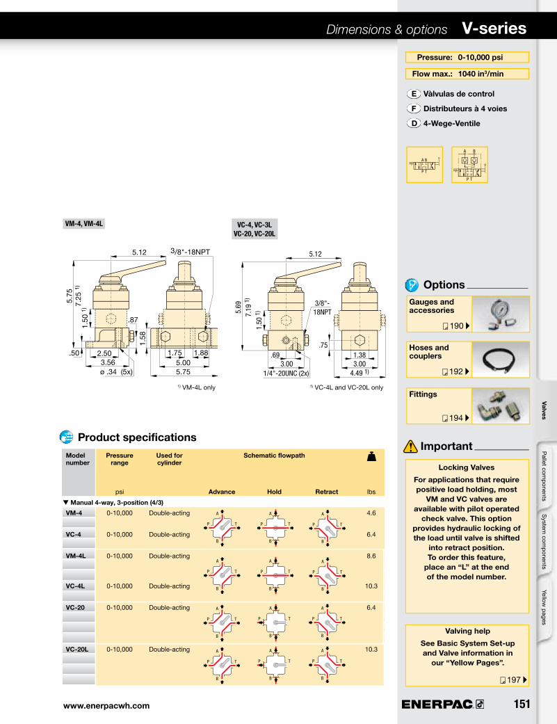
Pressure: 0-10,000 psi
Flow max.: 1040 in3/min
Gauges and accessories
Hoses and couplers
E Vàlvulas de control
F Distributeurs à 3 voies
D 3-Wege-Ventile
Options
Fittings
Important
Locking Valves
For applications that require positive load holding, most
VM and VC valves are available with pilot operated
check valve. This option provides hydraulic locking of the load until valve is shifted
into retract position. To order this feature,
place an “L” at the end of the model number.
Valving help
See Basic System Set-up and Valve information in our “Yellow Pages”.
Product specifications
Model Pressure Used for Schematic flowpath number range cylinder Advance Hold Retract psi lbs
t Manual 3-way, 2-position (3/2)
VM-2 0-10,000 Single-acting – 4.8
t Manual 3-way, 3-position (3/3)
VM-3 0-10,000 Single-acting 4.6
VC-3 0-10,000 Single-acting 6.4
t Manual 3-way, 3-position (3/3)
VM-3L 0-10,000 Single-acting 8.6
VC-3L 0-10,000 Single-acting 10.3
VC-15 0-10,000 Single-acting 6.4
VC-15L 0-10,000 Single-acting 10.3
1) VC-3L and VC-15L only1) VM-3L only
1.44 1.88
5.125.
25
1.12
5.00.385.75
ø.34 (6x)
1.12.81
.62
2.503.25
3/8"-18NPT
1.58
1.75 1.885.005.75
3/8"-18NPT
.87
2.50
.50 ø .34 (5x)3.56
1.50
1)
5.75
7.25
1)
5.12 5.12
3.00.69
3/8"-18NPT
1/4"-20UN (2x)
5.69
7.19
1)
1.50
1)
3.001.38
.75
4.49 1)
150 ®
A
P T
B
P T
A B
A
P T
B
P T
A B
99-1
39
99-1
20
Col
let-
Lok®
pr
oduc
t lin
eS
win
g cl
amps
Line
ar c
lam
psPo
wer
sou
rces
Valv
esW
ork
supp
orts
4-way directional manual control valves Application & selection
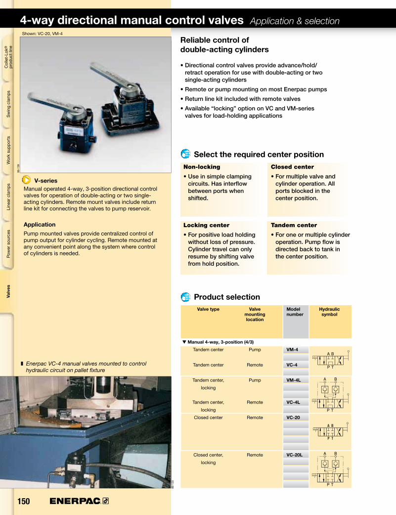
Reliable control of double-acting cylinders
• Directional control valves provide advance/hold/retract operation for use with double-acting or two single-acting cylinders
• Remote or pump mounting on most Enerpac pumps
• Return line kit included with remote valves
• Available “locking” option on VC and VM-series valves for load-holding applications
V-seriesManual operated 4-way, 3-position directional control valves for operation of double-acting or two single-acting cylinders. Remote mount valves include return line kit for connecting the valves to pump reservoir.
ApplicationPump mounted valves provide centralized control of pump output for cylinder cycling. Remote mounted at any convenient point along the system where control of cylinders is needed.
Shown: VC-20, VM-4
Select the required center position
z Enerpac VC-4 manual valves mounted to control hydraulic circuit on pallet fixture
Non-locking
• Use in simple clamping circuits. Has interflow between ports when shifted.
Closed center
• For multiple valve and cylinder operation. All ports blocked in the center position.
Locking center
• For positive load holding without loss of pressure. Cylinder travel can only resume by shifting valve from hold position.
Tandem center
• For one or multiple cylinder operation. Pump flow is directed back to tank in the center position.
Valve type Valve Model Hydraulic mounting number symbol location
t Manual 4-way, 3-position (4/3)
Tandem center Pump VM-4
Tandem center Remote VC-4
Tandem center, Pump VM-4L
locking
Tandem center, Remote VC-4L
locking
Closed center Remote VC-20
Closed center, Remote VC-20L
locking
Product selection
www.enerpacwh.com 151®
A
P T
B
P T
A B
190 ▸
192 ▸
194 ▸
197 ▸
P T
A
B
P T
A
B
P T
A
B
P T
A
B
P T
A
B
P T
A
B
VM-4, VM-4L VC-4, VC-3LVC-20, VC-20L
Pallet com
ponentsValves
System
components
Yellow pages
Pressure: 0-10,000 psi
Flow max.: 1040 in3/min
Gauges and accessories
Hoses and couplers
E Vàlvulas de control
F Distributeurs à 4 voies
D 4-Wege-Ventile
Options
Fittings
Important
Locking Valves
For applications that require positive load holding, most
VM and VC valves are available with pilot operated
check valve. This option provides hydraulic locking of the load until valve is shifted
into retract position. To order this feature,
place an “L” at the end of the model number.
Valving help
See Basic System Set-up and Valve information in
our “Yellow Pages”.
Product specificationsModel Pressure Used for Schematic flowpath
number range cylinder psi Advance Hold Retract lbs
Sequence valvesSequence valves block the oil to a secondary hydraulic circuit until pressure in the primary circuit reaches a preset level. The sequence valves have a built-in check system to allow the oil to flow back without external piping.
Pressure settings for the V-2000 can be adjusted by screwing the slotted pin in or out. The pressure settings for the other models is adjusted by loosening the jam nut and turn the set screw to reach your setting.
ApplicationThe sequence valves can be mounted in-line or fixture mounted using mounting bolts.
A typical application for the sequence valve would be to build pressure within work supports before the swing cylinders are applied to the supported part, to prevent deflection in the part.
z Two WVP-5 sequence valves used in conjunction with Enerpac WCA-series Auto Coupler to provide system automation.
Pressure Maximum Maximum Model Oil ports Opening A adjustment pressure oil flow number pressure range check valve
• Pressure setting between 500-5000 psi for secondary circuit is secured with lock nut
• Mounting holes on WVP-5, manifold mounting ports on MVPM-5
• MVPC-5 features cartridge body
V-2000
• Direct accurate pressure setting
• Pressure setting between 200-2000 psi for secondary circuit
• Flag indicator appears everytime the valve is operated
Seal material: Buna-N.Manifold O-rings included with MVPM-5. For manifold mounting installation information consult Enerpac for surface preparation.
(MVPM-5 only)manifold ports
* Holes #2 and #3 are for model WVP-5 Holes #1 through #4 are for model WVPM-5
Sealing edge
Product selection
Gauges and accessories
145
290
435
505
0 120 240 360 490 610
Oil flow (in3/min) u
MVPM-5, WVP-5 Pressure drop vs oil flow
Pres
sure
dro
p (p
si) u
7300
72
217
360
P-AA-P
1.12
G1/4
"
5.60
.49
.51
ø .19
1.461.972.36
1.04
2.561.97
.26
A
P
.50
.87
.94.7
9 m
ax1.
52.5
1
.55.02 min.32
Ø.39 max.
.51
.55
118°
.04
.22
32
2.72
+.004-.000
+.020-.000
Ø.945
Ø.945
.001
3.10
1.50
.751.34
3.40
A
1/8"-27NPT
1/8"-27NPT1.50
.28
2.00
.62
1.38
A
P
www.enerpacwh.com 153®
99_0
21
194 ▸
C
C
K
G
H
B
B
L
DA
A
P z
A B
F
F
E
G
CB
H
EDK
L
A
A
FAG
z
P
A D
LK
C
B
G
P
z
H
FGE
M
AB
B
A
P
Z
MVM-72MV-722B, -7202B
Pallet com
ponentsValves
System
components
Yellow pages
Product selection
For more information on ACL-series Accumulators see page 124.
Product dimensions in inches [ ]
Pilot Accumulator Maximum Maximum Model Oil ports Optional ratio included oil flow pressure number charging tool for ACL
GPM psi lbs
7 : 1 – 10 5000 V-72 SAE #4 – 4.0
7 : 1 ACL-22 10 5000 MV-722B G 1/4" WAT-2 6.0
7 : 1 ACL-202 10 5000 MV-7202B G 1/4" WAT-2 7.5
7 : 1 – 10 5000 MVM-72 G 1/4" – 3.0
Model number
MV, V-series Pilot operated check valves
Pilot ratio: 7:1
Flow: 10 gpm max.
E Válvulas antiretorno pilotada
F Clapets antiretour piloté
D Rückschlagventile
To hold cylinder load and ensure remote unlocking
• Fast check-off response
• Hardened seats ensure long life and positive pressure holding
• Built-in accumulator to maintain system pressure
• Mounting holes
• Manifold mount body MVM-72
Fittings
Options
MV and V-series
Pilot operated check valves check the oil flow with a built-in pilot circuit providing fast, automatic check-off for your workholding applications.
The pilot operated check valves with built-in accumulator help to maintain system pressure due to minor oil loss.
ApplicationAdded capability to open with pilot pressure to allow cylinders to retract. By using a pilot operated check valve, cylinder retraction can be accomplished automatically without operator activity.
Shown: V-72
= Cylinder advance
= Cylinder retract
= Pressure
= Pilot
Seal material: Buna-N.Manifold O-rings included with MVM-72. For manifold mounting installation information consult Enerpac for surface preparation.
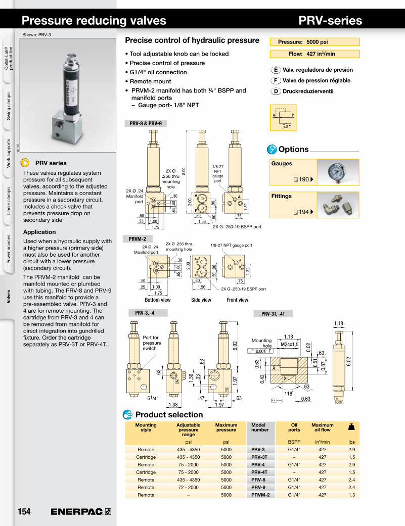
Mounting Adjustable Maximum Model Oil Maximum style pressure pressure number ports oil flow range
psi psi BSPP in3/min lbs
Remote 435 - 4350 5000 PRV-3 G1/4" 427 2.9
Cartridge 435 - 4350 5000 PRV-3T – 427 1.5
Remote 75 - 2000 5000 PRV-4 G1/4" 427 2.9
Cartridge 75 - 2000 5000 PRV-4T – 427 1.5
Remote 435 - 4350 5000 PRV-8 G1/4" 427 2.4
Remote 72 - 2000 5000 PRV-9 G1/4" 427 2.4
Remote – 5000 PRVM-2 G1/4" 427 1.3
Product selection
Pressure reducing valves PRV-series
Pressure: 5000 psi
Flow: 427 in3/min
E Válv. reguladora de presión
F Valve de pression réglable
D Druckreduzierventil
Precise control of hydraulic pressure
• Tool adjustable knob can be locked
• Precise control of pressure
• G1/4" oil connection
• Remote mount
• PRVM-2 manifold has both ¼" BSPP and manifold ports– Gauge port- 1/8" NPT
Options
PRV series
These valves regulates system pressure for all subsequent valves, according to the adjusted pressure. Maintains a constant pressure in a secondary circuit. Includes a check valve that prevents pressure drop on secondary side.
ApplicationUsed when a hydraulic supply with a higher pressure (primary side) must also be used for another circuit with a lower pressure (secondary circuit).
The PRVM-2 manifold can be manifold mounted or plumbed with tubing. The PRV-8 and PRV-9 use this manifold to provide a pre-assembled valve. PRV-3 and 4 are for remote mounting. The cartridge from PRV-3 and 4 can be removed from manifold for direct integration into gundrilled fixture. Order the cartridge separately as PRV-3T or PRV-4T.
Shown: PRV-3
Port for pressure switch
Mounting hole
Fittings
Gauges
Side viewBottom view Front view
2X Ø .24 Manifold
port
2X Ø .24 Manifold port
2X G-.250-19 BSPP port
2X G-.250-19 BSPP port
2X Ø .256 thru mounting
hole
2X Ø .256 thru mounting hole
1/8-27 NPT
gauge port
1/8-27 NPT gauge port
.63.471.97
1.97
6.02
.63
.63
.33
1.50
1.38G1/4"
6.02
1.18
118˚0.63
0.51
0.63
0.87
0.43
0,001
1.18M24x1,5
0.02
63
63
.60
.65
.50.25
.30
1.75
8.00
2.00
.90
.50
1.32
1.56.80 .75
1.00
.60
.65
.50.25
.30
1.75
2.00
.90
.50 1.
32
1.56.80 .75
1.00
www.enerpacwh.com 155®
A B
193 ▸
194 ▸
A B
A B
VFC-1, -2
99-0
25
VFC-1 = SAE #4VFC-2 = G¼˝
Pallet com
ponentsValves
System
components
Yellow pages
VFC-series Flow control valvesRegulate the flow of oil
• Poppet valve design for zero leakage• Color coded flow indicator
• Free flow return
• Fine metering capability
• Lockable
• Standard Viton seals
Product selection z In-line installation of a VFC-1 flow control valve.
Options
Max. Flow: 10 gpm
Pressure: 0-5000 psi
Fittings
High pressure filter
E Válv. reguladoras de caudal
F Valves de control débit
D Stromregelventile
Maximum Pressure Oil Model Flow path Maximum oil flow range ports number pressure drop gpm psi psi lbs
t Flow control valves
10 0-5000 SAE #4 VFC-1 1500 1.8
10 0-5000 G 1/4" VFC-2 1500 1.8
Seal material: Viton
0
Oil flow (gal/min) u
Flow setting (in turns) u
VFC-1, -2 Pressure drop vs oil flow
Pres
sure
dro
p (p
si) u
150
2 4 6 8 10 12 14
1 2 3 4 5 6 71500
Flow direction A-B
1400
1200
1000
800
600
400
200
VFC-seriesProvide repeatable oil flow control. The internal check valve allows metered flow in one direction and free flow in the opposite direction. Precise control is achieved with a micro-meter style adjustment knob, which can be locked with the set screw.
ApplicationUse VFC-series flow control valves in-line with the Enerpac WE-series workholding pump to protect your components from damage due to high flow rates.
Shown: VFC-1
HexFlat
1.342.17
.35.98
12.8
0
ø 1.20
2.532.
77
156 ®
99-0
86
99-1
22b
AP
P
A
A
P
PA
Col
let-
Lok®
pr
oduc
t lin
eS
win
g cl
amps
Line
ar c
lam
psPo
wer
sou
rces
Valv
esW
ork
supp
orts
Accessory valves Application & selection
Your hydraulic control solution
• Regulate oil flow or system pressure
• All valves feature NPT or SAE porting to insure against leakage at rated pressure
• Can easily be installed in any system
• All valves are painted, coated or plated for corrosion resistance
Accessory valves
Enerpac accessory valves are available in a wide variety and many configurations to control hydraulic pressure or oil flow. These valves are used in conjunction with other valves and system components to provide full automation and control.
ApplicationAccessory valves are used to automate clamp cycles, prevent pressure loss and provide additional operator and component safety.
Shown: HV-1000A, V-17, V-10, V-12, V-152
Product specificationHV-1000A Air pilot holding valve• Holds fluid under pressure
offering independent control of different branches of the same fixture
• Valve can control the pilot air and the booster in sequence
• Max. oil flow 305 in3/min
• Works with the VA-42 four-way air valve and a booster
Valve type Maximum Model Oil pressure number ports
psi
Holding valve, air pilot 3000 HV-1000A 1/8" NPT
Holding valve, modular 3000 MHV-1 1/8" NPT
Pressure limiting valve 3000 PLV-40013B 1/8" NPT
Manual shut-off valve 5000 V-12 SAE #4
Auto-damper valve 10,000 V-10 1/2" NPT
Safety check valve 10,000 V-17 3/8" NPT
Pressure relief valve 10,000 V-152 3/8" NPT
Product selection
z V-17 Safety check valve installed on a fixture.
MHV-1 Modular holding valve• Allows separate operation of clamping
fixtures with a single power source
• Ideal for applications when fluid feed lines are impractical. If system pressure is interrupted, the MHV-1 will hold the pressure beyond the valve
• Max. oil flow 305 in3/min
• To release system pressure, rotate valve handle in either direction 90˚ to release and retract system pressure
Air inlet.28
1.88
1/8"-27NPT
2.254.34
1.00
2.00
1/4"
-18
NPT
1/8"
-27N
PT
1.38
.28.75
5.06
1.38
1.38
3.31
1/8"- 27 NPT
.92
www.enerpacwh.com 157®
AP
158 ▸
190 ▸
192 ▸
194 ▸
197 ▸
P
P
A
PA
Pallet com
ponentsValves
System
components
Yellow pages
Dimensions & options MHV, HV, PLV, V-series
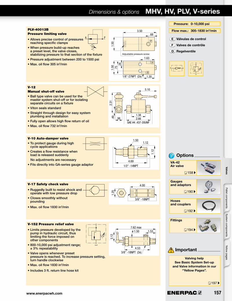
Pressure: 0-10,000 psi
Flow max.: 305-1830 in3/min
VA-42 Air valve
Gauges and adaptors
E Válvulas de control
F Valves de contrôle
D Regelventile
Options
Hoses and couplers
Important
Valving helpSee Basic System Set-up
and Valve information in our “Yellow Pages”.
Fittings
PLV-40013B Pressure limiting valve
• Allows precise control of pressures reaching specific clamps
• When pressure build-up reaches a preset level, the valve closes, stabilizing pressure to that section of the fixture
• Pressure adjustment between 200 to 1500 psi • Max. oil flow 305 in3/min
V-12 Manual shut-off valve• Ball type valve can be used for the
master system shut-off or for isolating separate circuits on a fixture
• Viton seals standard• Straight through design for easy system
plumbing and installation• Fully open allows high flow return of oil • Max. oil flow 732 in3/min
V-10 Auto-damper valve• To protect gauge during high
cycle applications • Creates a flow resistance when
load is released suddenly No adjustments are necessary • Fits directly into GA-series gauge adaptor
V-17 Safety check valve
• Ruggedly built to resist shock and operate with low pressure drop
• Closes smoothly without pounding
• Max. oil flow 1830 in3/min
V-152 Pressure relief valve
• Limits pressure developed by the pump in hydraulic circuit, thus limiting the force imposed on other components