92
NA 16.701 A 06 - 2016 TECHNICAL BROCHURE Air-water units with centrifugal fan Water chillers Series CIATCooler LP Air-water heat pumps Series CIATCooler ILP CIATCooler LP / ILP
NA 16.701 A 06 - 2016
TECHNICAL BROCHUREAir-water units with centrifugal fan
Water chillersSeries CIATCooler LP
Air-water heat pumpsSeries CIATCooler ILP
CIA
TC
oole
r LP
/ IL
P

HEAT PUMPS - AIR CONDITIONING - REFRIGERATION - AIR HANDLING - HEAT EXCHANGE - NA 16.701 A
Water chillers and air/water heat pumps
3
CIA
TCoo
ler L
P
ContentsDescription...............................................................................................................................................................................................................5
Series ......................................................................................................................................................................................................................5
Range ......................................................................................................................................................................................................................5
Operation limits........................................................................................................................................................................................................5
Designation..............................................................................................................................................................................................................6
Unit components......................................................................................................................................................................................................6
Casing ...............................................................................................................................................................................................................6
Outdoor circuit ...................................................................................................................................................................................................6
Indoor circuit ......................................................................................................................................................................................................6
Cooling circuit ....................................................................................................................................................................................................6
Electric panel .....................................................................................................................................................................................................6
Protections ........................................................................................................................................................................................................7
Version with circulation pump included (LPC / ILPC) ........................................................................................................................................7
CONNECT2 electronic control ..........................................................................................................................................................................8
Options ..............................................................................................................................................................................................................9
Unit's operating range ..........................................................................................................................................................................................10
Seasonal performance ..........................................................................................................................................................................................10
DEGIPAC defrosting system .................................................................................................................................................................................10
STD version: technical characteristics...................................................................................................................................................................11
STD version: technical characteristics with pump included LPC / ILPC ................................................................................................................13
Graphs of pressure drops in STD version .............................................................................................................................................................14
HEE version: technical characteristics ..................................................................................................................................................................15
HEE version: technical characteristics with pump included LPC / ILPC................................................................................................................17
Graphs of pressure drops in HEE version .............................................................................................................................................................18
Electrical heater with hydraulic module .................................................................................................................................................................19
Auxiliary heating management ..............................................................................................................................................................................19
Pressure drops in the mesh fi lter (sent in the kit) .................................................................................................................................................19
Minimum volume of water admissible in the installation (cooling mode) ...............................................................................................................20
Circulation pumps available for LPC / ILPC .........................................................................................................................................................20
Schematic diagram of the hydraulic circuit ............................................................................................................................................................21
Cooling capacity of the STD version (kW) .............................................................................................................................................................23
Heating capacity of the STD version (kW).............................................................................................................................................................27
Cooling capacity of the HEE version (kW).............................................................................................................................................................31
Heating capacity of the HEE version (kW) ............................................................................................................................................................35
Evaporator operating limits ....................................................................................................................................................................................38
Operation with glycol water ...................................................................................................................................................................................38
Corrosion behaviour ..............................................................................................................................................................................................39
Cooling recovery circuit (optional) .........................................................................................................................................................................40
Sound levels ..........................................................................................................................................................................................................49
Dimension schemes for the STD version ..............................................................................................................................................................50
Dimension schemes for the HEE version ..............................................................................................................................................................69
Dimensions of air fl exible ducts (option) ................................................................................................................................................................84
Gravimetric fi lters in the return air (option) ............................................................................................................................................................86
Airfl ow characteristics: selection of fan motors, STD version ................................................................................................................................87
Airfl ow characteristics: selection of fan motors, HEE version................................................................................................................................88
Assembly recommendations .................................................................................................................................................................................89

HEAT PUMPS - AIR CONDITIONING - REFRIGERATION - AIR HANDLING - HEAT EXCHANGE - NA 16.701 A
Water chillers and air/water heat pumps
5
CIA
TCoo
ler L
P
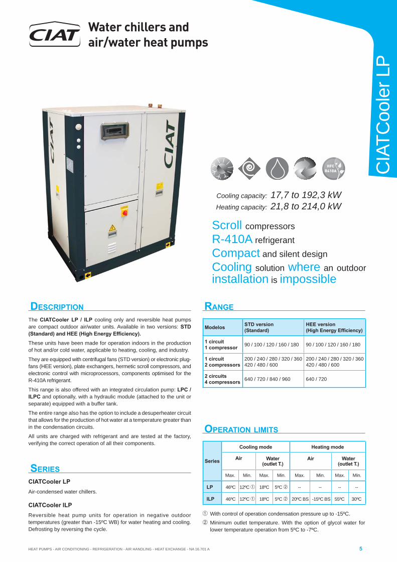
DESCRIPTIONThe CIATCooler LP / ILP cooling only and reversible heat pumps are compact outdoor air/water units. Available in two versions: STD (Standard) and HEE (High Energy Effi ciency). These units have been made for operation indoors in the production of hot and/or cold water, applicable to heating, cooling, and industry.
They are equipped with centrifugal fans (STD version) or electronic plug-fans (HEE version), plate exchangers, hermetic scroll compressors, and electronic control with microprocessors, components optimised for the R-410A refrigerant.
This range is also offered with an integrated circulation pump: LPC / ILPC and optionally, with a hydraulic module (attached to the unit or separate) equipped with a buffer tank.
The entire range also has the option to include a desuperheater circuit that allows for the production of hot water at a temperature greater than in the condensation circuits.
All units are charged with refrigerant and are tested at the factory, verifying the correct operation of all their components.
RANGE
SERIESCIATCooler LPAir-condensed water chillers.
CIATCooler ILPReversible heat pump units for operation in negative outdoor temperatures (greater than -15ºC WB) for water heating and cooling. Defrosting by reversing the cycle.
OPERATION LIMITS
With control of operation condensation pressure up to -15ºC.
Minimum outlet temperature. With the option of glycol water for lower temperature operation from 5ºC to -7ºC.
Scroll compressorsR-410A refrigerantCompact and silent designCooling solution where an outdoorinstallation is impossible
Cooling capacity:
Heating capacity:
17,7 to 192,3 kW21,8 to 214,0 kW
Modelos STD version(Standard)
HEE version (High Energy Effi ciency)
1 circuit1 compressor 90 / 100 / 120 / 160 / 180 90 / 100 / 120 / 160 / 180
1 circuit2 compressors
200 / 240 / 280 / 320 / 360 420 / 480 / 600
200 / 240 / 280 / 320 / 360420 / 480 / 600
2 circuits4 compressors 640 / 720 / 840 / 960 640 / 720
Series
Cooling mode Heating mode
Air Water (outlet T.)
Air Water (outlet T.)
Max. Min. Max. Min. Max. Min. Max. Min.
LP 46ºC 12ºC 18ºC 5ºC -- -- -- --
ILP 46ºC 12ºC 18ºC 5ºC 20ºC BS -15ºC BS 55ºC 30ºC
Water chillers and air/water heat pumps
HEAT PUMPS - AIR CONDITIONING - REFRIGERATION - AIR HANDLING - HEAT EXCHANGE - NA 16.701 A6
CIATCooler LP
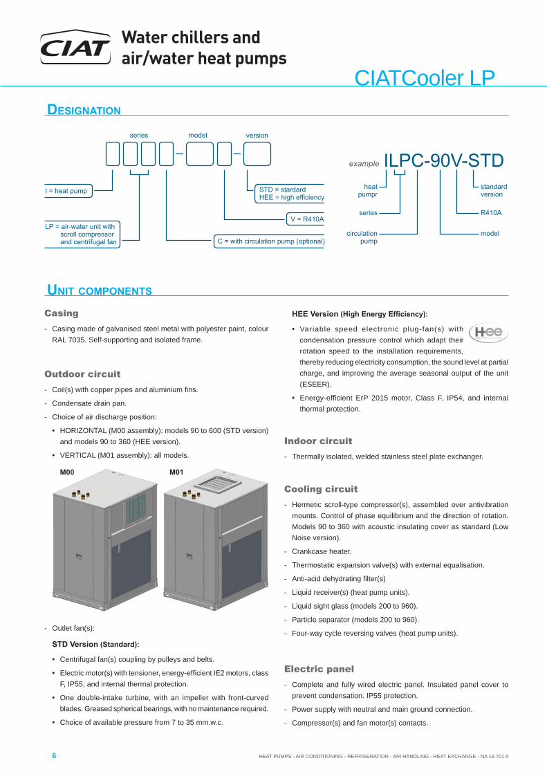
UNIT COMPONENTS
Casing- Casing made of galvanised steel metal with polyester paint, colour
RAL 7035. Self-supporting and isolated frame.
Outdoor circuit- Coil(s) with copper pipes and aluminium fi ns.
- Condensate drain pan.
- Choice of air discharge position:
• HORIZONTAL (M00 assembly): models 90 to 600 (STD version) and models 90 to 360 (HEE version).
• VERTICAL (M01 assembly): all models.
Electric panel- Complete and fully wired electric panel. Insulated panel cover to
prevent condensation. IP55 protection.
- Power supply with neutral and main ground connection.
- Compressor(s) and fan motor(s) contacts.
Cooling circuit- Hermetic scroll-type compressor(s), assembled over antivibration
mounts. Control of phase equilibrium and the direction of rotation. Models 90 to 360 with acoustic insulating cover as standard (Low Noise version).
- Crankcase heater.
- Thermostatic expansion valve(s) with external equalisation.
- Anti-acid dehydrating fi lter(s)
- Liquid receiver(s) (heat pump units).
- Liquid sight glass (models 200 to 960).
- Particle separator (models 200 to 960).
- Four-way cycle reversing valves (heat pump units).
Indoor circuit- Thermally isolated, welded stainless steel plate exchanger.
- Outlet fan(s):
STD Version (Standard):
• Centrifugal fan(s) coupling by pulleys and belts.
• Electric motor(s) with tensioner, energy-effi cient IE2 motors, class F, IP55, and internal thermal protection.
• One double-intake turbine, with an impeller with front-curved blades. Greased spherical bearings, with no maintenance required.
• Choice of available pressure from 7 to 35 mm.w.c.
M00 M01
DESIGNATION
ILPC-90V-STD
model
R410A
standardversion
series model
example
heatpumpr
circulationpump
series
I = heat pump
V = R410ALP = air-water unit with
scroll compressorand centrifugal fan C = with circulation pump (optional)
version
STDHEE
= stardard= high efficiency
HEE Version (High Energy Effi ciency):
• Variable speed electronic plug-fan(s) with condensation pressure control which adapt their rotation speed to the installation requirements, thereby reducing electricity consumption, the sound level at partial charge, and improving the average seasonal output of the unit (ESEER).
• Energy-effi cient ErP 2015 motor, Class F, IP54, and internal thermal protection.
HEAT PUMPS - AIR CONDITIONING - REFRIGERATION - AIR HANDLING - HEAT EXCHANGE - NA 16.701 A
Water chillers and air/water heat pumps
7
CIA
TCoo
ler L
P
Protections- High pressure pressostat.
- Low pressure safety device integrated into the control.
- Water fl ow controller.
- Water anti-freeze protection built into the control, depending on the temperature measured by the probe placed on the exchanger outlet.
- Water anti-freeze thermostat as additional safety.
- Compressor discharge temperature control.
- Non-return valve built into the compressor discharge.
- Compressor thermal protection.
- Main door switch.
- Automatic switch in the control circuit.
- Magnetothermic protection switches for the compressor(s) power line and fan motor.
- Timing the disconnection of the circulation pump.
- Failure safety device for the circulation pump.
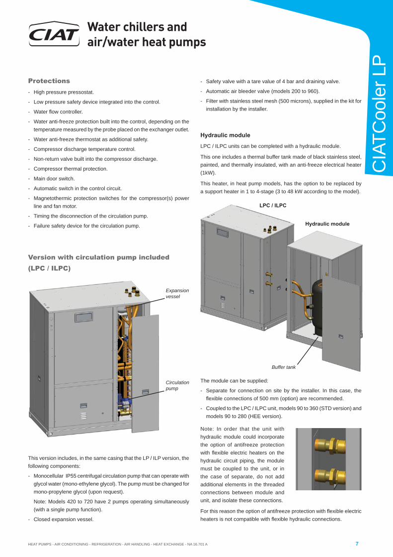
Version with circulation pump included (LPC / ILPC)
Expansionvessel
Circulationpump
This version includes, in the same casing that the LP / ILP version, the following components:
- Monocellular IP55 centrifugal circulation pump that can operate with glycol water (mono-ethylene glycol). The pump must be changed for mono-propylene glycol (upon request).
Note: Models 420 to 720 have 2 pumps operating simultaneously (with a single pump function).
- Closed expansion vessel.
- Safety valve with a tare value of 4 bar and draining valve.
- Automatic air bleeder valve (models 200 to 960).
- Filter with stainless steel mesh (500 microns), supplied in the kit for installation by the installer.
Hydraulic module
LPC / ILPC units can be completed with a hydraulic module.
This one includes a thermal buffer tank made of black stainless steel, painted, and thermally insulated, with an anti-freeze electrical heater (1kW).
This heater, in heat pump models, has the option to be replaced by a support heater in 1 to 4-stage (3 to 48 kW according to the model).
LPC / ILPC
Hydraulic module
Buffer tank
The module can be supplied:
- Separate for connection on site by the installer. In this case, the fl exible connections of 500 mm (option) are recommended.
- Coupled to the LPC / ILPC unit, models 90 to 360 (STD version) and models 90 to 280 (HEE version).
Note: In order that the unit with hydraulic module could incorporate the option of antifreeze protection with fl exible electric heaters on the hydraulic circuit piping, the module must be coupled to the unit, or in the case of separate, do not add additional elements in the threaded connections between module and unit, and isolate these connections.
For this reason the option of antifreeze protection with fl exible electric heaters is not compatible with fl exible hydraulic connections.

Water chillers and air/water heat pumps
HEAT PUMPS - AIR CONDITIONING - REFRIGERATION - AIR HANDLING - HEAT EXCHANGE - NA 16.701 A8
CIATCooler LP
Functions
• Run, Stop, Reset or Remote control functions.
• Selection of COOLING or HEATING operating mode.
• Display of the information related to operations for direct display of multi-lingual messages in clear text.
• Direct display of the water temperatures and pressures.
• Complete management of compressors with a start-up sequence, count, and equalisation of operating times.
• Anti-short-circuit protection.
• Auto-adaptive and pro-active functions, adjusting the control in the compensation for the parameters.
• Device to reduce the stratifi ed power being cascaded to the multi-compressors, based on the cooling or heating needs controlled by the water temperatures.
• Control of the internal operating parameters.
• Management of auxiliary electrical heater working alone or simultaneous to the heating pump.
• Adjustment of the setpoint with a 4-20 mA signal.
• Management of a second setpoint.
• Diagnosis of the operating and failure states:
HP/LP, water fl ow, compressor motor(s), anti-frost.
• Remote management and surveillance.
• Master/slave management capable of managing two units in a single water loop, alternating the Master and Slave based on the operating times.
• Hourly and weekly programming.
CONNECT2 electronic controlElectronic control module with microprocessor and CPU, central automation, and access to the internal operating states.
Composition of the main board
• Input for adquisition of sensors reading and operating state of components.
• Outputs for circulation pump control, stages connection, and general failure signal.
• Connector for local control panel, installed on the unit.
• Connector for remote control panel (optional).
• Connector for relay card (optional).
• Connector for management - MULTICONNECT (optional).
• RS485 output via the MODBUS-JBUS protocol for the GTC link.
Local control panel
Ergonomic interface panel with multi-lingual LCD display (4 lines of 24 characters each) and LED indicators.
Functions
• Reading of pressures and temperatures.
• Operating state and fault diagnostics.
• Master/slave management of two parallel-connected machines.
• Fault memory management.
Relay board (optional)
Volt-free contacts card for display of the operation state and signalling of components failure. Available outputs:
• Failures: water flow, antifreeze, pump, fans, high and low pressures, compressors safety, discharge temperature.
• Operation state of compressors.
Multigroups management - MULTICONNECT (optional)
Main functions available:
• Management of up to 8 units in a single water loop.
• Management in COOLING mode (cold water group) or HEATING mode (heat pump).
• Management of the cold water or hot water network pumps.
• Integrated management of a backup unit.
• Unit load shedding.
• Timer programming of the installation.
• Management of the energy storage method.
• Balancing of the unit operating times.
• RS485 output via the MODBUS-JBUS protocol for the GTC link.
Serial RS485 outputs
• MODBUS - JBUS open protocol (standard).
• LONWORKS®, BACNET IP & BACNET MSTP protocols (optional).
• ETHERNET bridge (standard).
CONNECT2 control allows that all CIAT products can be integrated into monitoring systems:
• Smart CIATControl
• Easy CIATControl: Optimal Water® functions /Optimal start & stop / Night cooling
• Power’Control, Cristo’Control
• CIATM2M
Remote control panel (optional)
Functions and design identical to the local panel.
• Pumps management.
• Hourly and weekly programming.
HEAT PUMPS - AIR CONDITIONING - REFRIGERATION - AIR HANDLING - HEAT EXCHANGE - NA 16.701 A
Water chillers and air/water heat pumps
9
CIA
TCoo
ler L
P
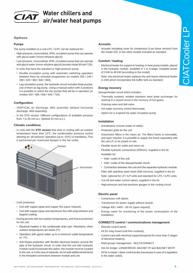
Damper
Servomotor
Options
PumpsThe pump installed on a unit LPC / ILPC can be replaced for:
- High-pressure, monocellular, IP55, circulation pump that can operate with glycol water (mono-ethylene glycol).
- Low-pressure, monocellular, IP55, circulation pump that can operate with glycol water (mono-ethylene glycol) (except model 90 and 720).
- In units that have the standard or high-pressure pump:
• Double circulation pump with automatic switching operation between them by schedule programmer (in models 200 / 240 / 280 / 320 / 360 / 840 / 960).
• Lag circulation pump, the hydraulic circuit includes three pumps, one of them as lag pump. Using a manual switch with 3 positions it is possible to select the two pumps that will be in operation (in models 420 / 480 / 600 / 640 / 720).
Confi guration- VERTICAL air discharge, M01 assembly (default horizontal
discharge, M00 assembly).
- In the STD version: Different confi gurations of available pressure from 7 to 35 mm.w.c. (default 20 mm.w.c.).
Installation- Antivibration mounts made of rubber.
- Protection grille for the coil.
- Gravimetric fi lters in the return air. The fi lters frame is removable, and upon request, it is possible to supply the frame separately with the unit LP, to be joined on site.
- Flexible ducts for outlet and return air.
- Flexible hydraulic connections (500mm), supplied in the kit.
Available for:
• Inlet / outlet of the unit.
• Inlet / outlet of the desuperheater circuit.
• Connection between the unit and the separate hydraulic module.
- Filter with stainless steel mesh (500 microns), supplied in the kit.
Note: optional for LP / ILP units and standard for LPC / ILPC units.
- Cut-off and water control valves, supplied in the kit.
- High-pressure and low-pressure gauges in the cooling circuit.
Energy recoveryDesuperheater circuit which includes:
- Thermally isolated, welded stainless steel plate exchanger for working in a closed circuit in the recovery of hot gases.
- Draining valve and ball valve
- Hot water recovery control thermostat.
- Option for a 3-speed hot water circulation pump.
Comfort / heating- Electrical heater for support in heating, in heat pump models, placed
in the hydraulic module, available in 1 to 4-stage. Available power of 3 kW to 48 kW (according to the model).
Note: this electrical heater replaces the anti-freeze electrical heater (1 kW) which incorporates the buffer tank as standard.
- Coils protection:
• Coil with copper pipes and copper fi ns (upon request).
• Coil with copper pipes and aluminium fi ns with polyurethane and blygold coating.
- During periods with low outdoor temperatures, anti-freeze protection for the unit:
• Electrical heaters in the condensate drain pan. Mandatory whenoutdoor temperatures are below 3°C.
• Operation with glycol water up to a minimum outlet temperature of -7ºC.
• Anti-freeze protection with fl exible electrical heaters around the pipe of the hydraulic circuit. In order that the unit with hydraulic module could incorporate this option, the module must be coupled to the unit, or in the case of separate, do not add additional elements in the threaded connections between module and unit.
Electric panel- Compressor soft starter.
- Transformer for power supply without neutral.
- Voltage 400 / 440V - 60 Hz (upon request).
- Energy meter for monitoring of the power consumption of the installation.
CONNECT2 control / communications management - Remote control panel.
- Kit for relay board (volt-free contacts).
- Control card with electrical support(required for more than 2 stages of electrical heaters).
- Multi-groups management - MULTICONNECT.
- Kits for bridge: LONWORKS®, BACNET IP and BACNET MSTP.
- Kit for a master / slave control probe (necessary in case of a regulation in the water outlet).
Acoustic - Acoustic insulating cover for compressor (Low Noise version) from
the model 420. In the other models included as standard.
Climatic conditions- In units with the STD version that work in cooling with an outdoor
temperature lower than 12ºC, the condensation pressure control allowing an “all seasons” operation (up to -15ºC) is mandatory. This is performed per motorized damper in the fan outlet.
Water chillers and air/water heat pumps
HEAT PUMPS - AIR CONDITIONING - REFRIGERATION - AIR HANDLING - HEAT EXCHANGE - NA 16.701 A10
CIATCooler LP
06-fe
br
Gai
n C
OP
13-fe
br
20-fe
br
27-fe
br
06-m
ar
13-m
ar
20-m
ar
115%
110%
105%
100%
95%
Standard
DEGIPAC
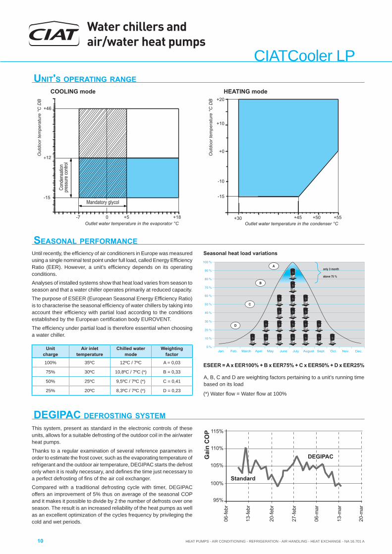
DEGIPAC DEFROSTING SYSTEMThis system, present as standard in the electronic controls of these units, allows for a suitable defrosting of the outdoor coil in the air/water heat pumps.
Thanks to a regular examination of several reference parameters in order to estimate the frost cover, such as the evaporating temperature of refrigerant and the outdoor air temperature, DEGIPAC starts the defrost only when it is really necessary, and defi nes the time just necessary to a perfect defrosting of fi ns of the air coil exchanger.
Compared with a traditional defrosting cycle with timer, DEGIPAC offers an improvement of 5% thus on average of the seasonal COP and it makes it possible to divide by 2 the number of defrosts over one season. The result is an increased reliability of the heat pumps as well as an excellent optimization of the cycles frequency by privileging the cold and wet periods.
SEASONAL PERFORMANCEUntil recently, the effi ciency of air conditioners in Europe was measured using a single nominal test point under full load, called Energy Effi ciency Ratio (EER). However, a unit’s effi ciency depends on its operating conditions.
Analyses of installed systems show that heat load varies from season to season and that a water chiller operates primarily at reduced capacity.
The purpose of ESEER (European Seasonal Energy Effi ciency Ratio) is to characterise the seasonal effi ciency of water chillers by taking into account their effi ciency with partial load according to the conditions established by the European certifi cation body EUROVENT.
The effi ciency under partial load is therefore essential when choosing a water chiller.
Seasonal heat load variations
ESEER = A x EER100% + B x EER75% + C x EER50% + D x EER25%
A, B, C and D are weighting factors pertaining to a unit’s running time based on its load
(*) Water fl ow = Water fl ow at 100%
Jan.. Feb. March April May June July August Sept. Oct. Nov. Dec.
only 3 month above 75 %
Unit charge
Air inlet temperature
Chilled water mode
Weightingfactor
100% 35ºC 12ºC / 7ºC A = 0,03
75% 30ºC 10,8ºC / 7ºC (*) B = 0,33
50% 25ºC 9,5ºC / 7ºC (*) C = 0,41
25% 20ºC 8,3ºC / 7ºC (*) D = 0,23
UNIT'S OPERATING RANGE
+55+50+45+30
+20
+10
+0
-10
-15
Out
door
tem
pera
ture
°C
DB
Outlet water temperature in the condenser °C+18+50-7
-15
+46
Out
door
tem
pera
ture
°C
DB
Mandatory glycol
Outlet water temperature in the evaporator °C
Cond
ensa
tion
pres
sure
contr
ol
COOLING mode HEATING mode
HEAT PUMPS - AIR CONDITIONING - REFRIGERATION - AIR HANDLING - HEAT EXCHANGE - NA 16.701 A
Water chillers and air/water heat pumps
11
CIA
TCoo
ler L
P
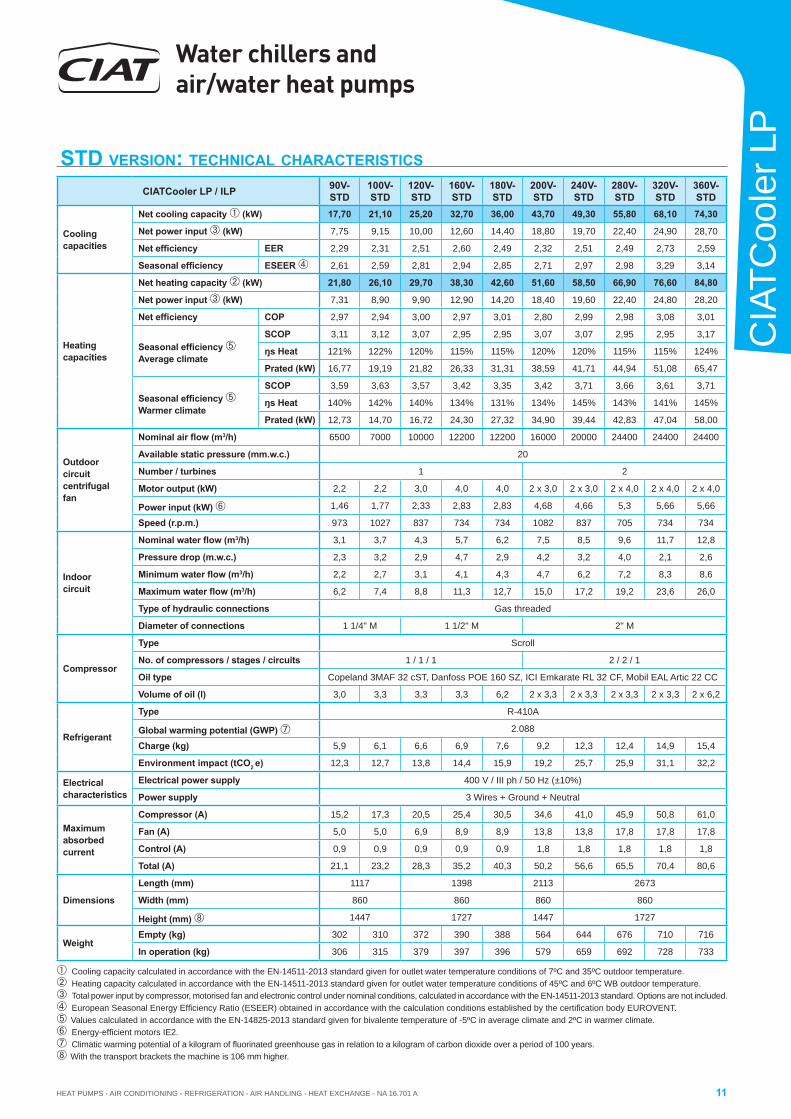
STD VERSION: TECHNICAL CHARACTERISTICS
CIATCooler LP / ILP 90V-STD
100V-STD
120V-STD
160V-STD
180V-STD
200V-STD
240V-STD
280V-STD
320V-STD
360V-STD
Cooling capacities
Net cooling capacity (kW) 17,70 21,10 25,20 32,70 36,00 43,70 49,30 55,80 68,10 74,30
Net power input (kW) 7,75 9,15 10,00 12,60 14,40 18,80 19,70 22,40 24,90 28,70
Net effi ciency EER 2,29 2,31 2,51 2,60 2,49 2,32 2,51 2,49 2,73 2,59
Seasonal effi ciency ESEER 2,61 2,59 2,81 2,94 2,85 2,71 2,97 2,98 3,29 3,14
Heating capacities
Net heating capacity (kW) 21,80 26,10 29,70 38,30 42,60 51,60 58,50 66,90 76,60 84,80
Net power input (kW) 7,31 8,90 9,90 12,90 14,20 18,40 19,60 22,40 24,80 28,20
Net effi ciency COP 2,97 2,94 3,00 2,97 3,01 2,80 2,99 2,98 3,08 3,01
Seasonal effi ciency Average climate
SCOP 3,11 3,12 3,07 2,95 2,95 3,07 3,07 2,95 2,95 3,17
ŋs Heat 121% 122% 120% 115% 115% 120% 120% 115% 115% 124%
Prated (kW) 16,77 19,19 21,82 26,33 31,31 38,59 41,71 44,94 51,08 65,47
Seasonal effi ciency Warmer climate
SCOP 3,59 3,63 3,57 3,42 3,35 3,42 3,71 3,66 3,61 3,71
ŋs Heat 140% 142% 140% 134% 131% 134% 145% 143% 141% 145%
Prated (kW) 12,73 14,70 16,72 24,30 27,32 34,90 39,44 42,83 47,04 58,00
Outdoorcircuit centrifugal fan
Nominal air fl ow (m3/h) 6500 7000 10000 12200 12200 16000 20000 24400 24400 24400
Available static pressure (mm.w.c.) 20
Number / turbines 1 2
Motor output (kW) 2,2 2,2 3,0 4,0 4,0 2 x 3,0 2 x 3,0 2 x 4,0 2 x 4,0 2 x 4,0
Power input (kW) 1,46 1,77 2,33 2,83 2,83 4,68 4,66 5,3 5,66 5,66
Speed (r.p.m.) 973 1027 837 734 734 1082 837 705 734 734
Indoor circuit
Nominal water fl ow (m3/h) 3,1 3,7 4,3 5,7 6,2 7,5 8,5 9,6 11,7 12,8
Pressure drop (m.w.c.) 2,3 3,2 2,9 4,7 2,9 4,2 3,2 4,0 2,1 2,6
Minimum water fl ow (m3/h) 2,2 2,7 3,1 4,1 4,3 4,7 6,2 7,2 8,3 8,6
Maximum water fl ow (m3/h) 6,2 7,4 8,8 11,3 12,7 15,0 17,2 19,2 23,6 26,0
Type of hydraulic connections Gas threaded
Diameter of connections 1 1/4" M 1 1/2" M 2" M
Compressor
Type Scroll
No. of compressors / stages / circuits 1 / 1 / 1 2 / 2 / 1
Oil type Copeland 3MAF 32 cST, Danfoss POE 160 SZ, ICI Emkarate RL 32 CF, Mobil EAL Artic 22 CC
Volume of oil (l) 3,0 3,3 3,3 3,3 6,2 2 x 3,3 2 x 3,3 2 x 3,3 2 x 3,3 2 x 6,2
Refrigerant
Type R-410A
Global warming potential (GWP) 2.088
Charge (kg) 5,9 6,1 6,6 6,9 7,6 9,2 12,3 12,4 14,9 15,4
Environment impact (tCO2 e) 12,3 12,7 13,8 14,4 15,9 19,2 25,7 25,9 31,1 32,2
Electrical characteristics
Electrical power supply 400 V / III ph / 50 Hz (±10%)
Power supply 3 Wires + Ground + Neutral
Maximum absorbed current
Compressor (A) 15,2 17,3 20,5 25,4 30,5 34,6 41,0 45,9 50,8 61,0
Fan (A) 5,0 5,0 6,9 8,9 8,9 13,8 13,8 17,8 17,8 17,8
Control (A) 0,9 0,9 0,9 0,9 0,9 1,8 1,8 1,8 1,8 1,8
Total (A) 21,1 23,2 28,3 35,2 40,3 50,2 56,6 65,5 70,4 80,6
Dimensions
Length (mm) 1117 1398 2113 2673
Width (mm) 860 860 860 860
Height (mm) 1447 1727 1447 1727
WeightEmpty (kg) 302 310 372 390 388 564 644 676 710 716
In operation (kg) 306 315 379 397 396 579 659 692 728 733
Cooling capacity calculated in accordance with the EN-14511-2013 standard given for outlet water temperature conditions of 7ºC and 35ºC outdoor temperature. Heating capacity calculated in accordance with the EN-14511-2013 standard given for outlet water temperature conditions of 45ºC and 6ºC WB outdoor temperature. Total power input by compressor, motorised fan and electronic control under nominal conditions, calculated in accordance with the EN-14511-2013 standard. Options are not included. European Seasonal Energy Effi ciency Ratio (ESEER) obtained in accordance with the calculation conditions established by the certifi cation body EUROVENT.Values calculated in accordance with the EN-14825-2013 standard given for bivalente temperature of -5ºC in average climate and 2ºC in warmer climate.Energy-effi cient motors IE2.Climatic warming potential of a kilogram of fl uorinated greenhouse gas in relation to a kilogram of carbon dioxide over a period of 100 years.With the transport brackets the machine is 106 mm higher.
Water chillers and air/water heat pumps
HEAT PUMPS - AIR CONDITIONING - REFRIGERATION - AIR HANDLING - HEAT EXCHANGE - NA 16.701 A12
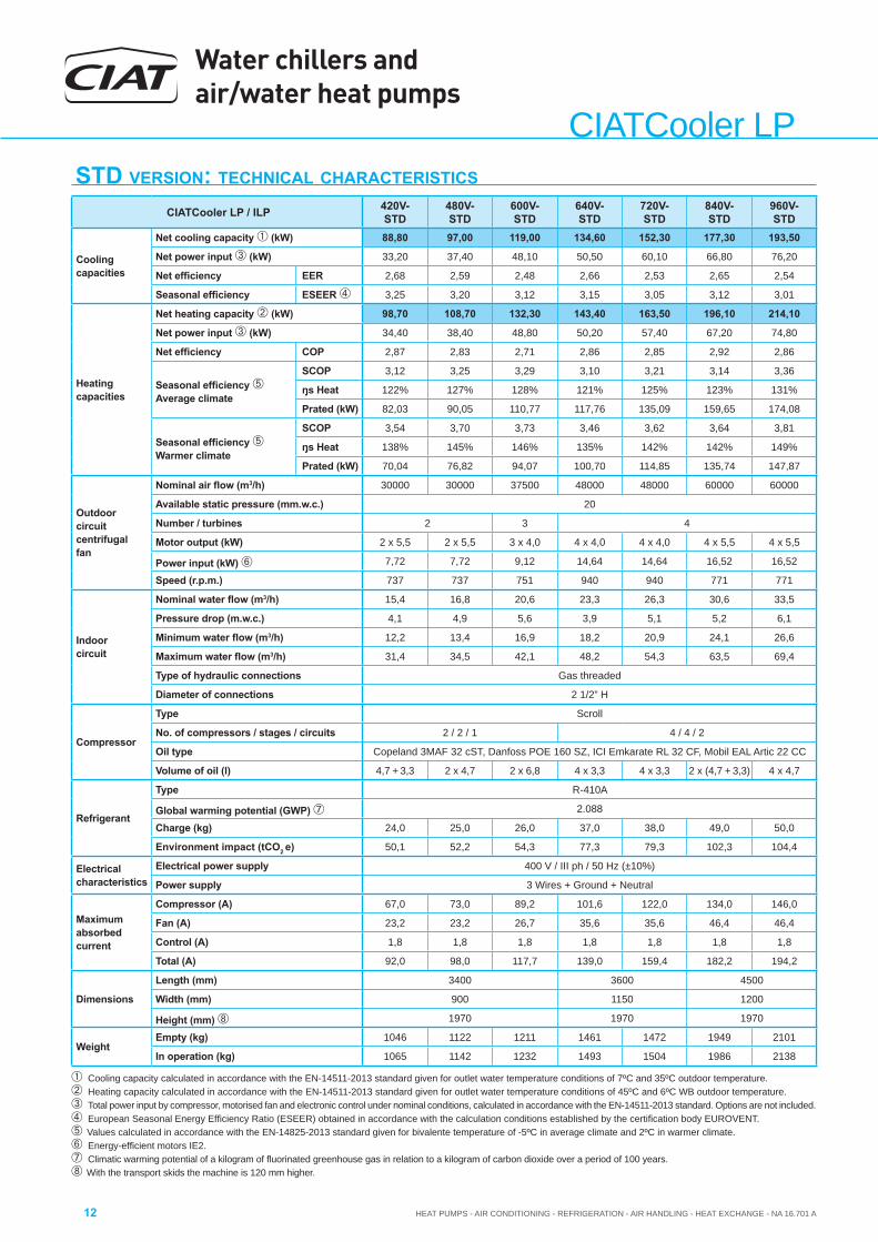
CIATCooler LPSTD VERSION: TECHNICAL CHARACTERISTICS
CIATCooler LP / ILP 420V-STD
480V-STD
600V-STD
640V-STD
720V-STD
840V-STD
960V-STD
Cooling capacities
Net cooling capacity (kW) 88,80 97,00 119,00 134,60 152,30 177,30 193,50
Net power input (kW) 33,20 37,40 48,10 50,50 60,10 66,80 76,20
Net effi ciency EER 2,68 2,59 2,48 2,66 2,53 2,65 2,54
Seasonal effi ciency ESEER 3,25 3,20 3,12 3,15 3,05 3,12 3,01
Heating capacities
Net heating capacity (kW) 98,70 108,70 132,30 143,40 163,50 196,10 214,10
Net power input (kW) 34,40 38,40 48,80 50,20 57,40 67,20 74,80
Net effi ciency COP 2,87 2,83 2,71 2,86 2,85 2,92 2,86
Seasonal effi ciency Average climate
SCOP 3,12 3,25 3,29 3,10 3,21 3,14 3,36
ŋs Heat 122% 127% 128% 121% 125% 123% 131%
Prated (kW) 82,03 90,05 110,77 117,76 135,09 159,65 174,08
Seasonal effi ciency Warmer climate
SCOP 3,54 3,70 3,73 3,46 3,62 3,64 3,81
ŋs Heat 138% 145% 146% 135% 142% 142% 149%
Prated (kW) 70,04 76,82 94,07 100,70 114,85 135,74 147,87
Outdoorcircuit centrifugal fan
Nominal air fl ow (m3/h) 30000 30000 37500 48000 48000 60000 60000
Available static pressure (mm.w.c.) 20
Number / turbines 2 3 4
Motor output (kW) 2 x 5,5 2 x 5,5 3 x 4,0 4 x 4,0 4 x 4,0 4 x 5,5 4 x 5,5
Power input (kW) 7,72 7,72 9,12 14,64 14,64 16,52 16,52
Speed (r.p.m.) 737 737 751 940 940 771 771
Indoor circuit
Nominal water fl ow (m3/h) 15,4 16,8 20,6 23,3 26,3 30,6 33,5
Pressure drop (m.w.c.) 4,1 4,9 5,6 3,9 5,1 5,2 6,1
Minimum water fl ow (m3/h) 12,2 13,4 16,9 18,2 20,9 24,1 26,6
Maximum water fl ow (m3/h) 31,4 34,5 42,1 48,2 54,3 63,5 69,4
Type of hydraulic connections Gas threaded
Diameter of connections 2 1/2” H
Compressor
Type Scroll
No. of compressors / stages / circuits 2 / 2 / 1 4 / 4 / 2
Oil type Copeland 3MAF 32 cST, Danfoss POE 160 SZ, ICI Emkarate RL 32 CF, Mobil EAL Artic 22 CC
Volume of oil (l) 4,7 + 3,3 2 x 4,7 2 x 6,8 4 x 3,3 4 x 3,3 2 x (4,7 + 3,3) 4 x 4,7
Refrigerant
Type R-410A
Global warming potential (GWP) 2.088
Charge (kg) 24,0 25,0 26,0 37,0 38,0 49,0 50,0
Environment impact (tCO2 e) 50,1 52,2 54,3 77,3 79,3 102,3 104,4
Electrical characteristics
Electrical power supply 400 V / III ph / 50 Hz (±10%)
Power supply 3 Wires + Ground + Neutral
Maximum absorbed current
Compressor (A) 67,0 73,0 89,2 101,6 122,0 134,0 146,0
Fan (A) 23,2 23,2 26,7 35,6 35,6 46,4 46,4
Control (A) 1,8 1,8 1,8 1,8 1,8 1,8 1,8
Total (A) 92,0 98,0 117,7 139,0 159,4 182,2 194,2
Dimensions
Length (mm) 3400 3600 4500
Width (mm) 900 1150 1200
Height (mm) 1970 1970 1970
WeightEmpty (kg) 1046 1122 1211 1461 1472 1949 2101
In operation (kg) 1065 1142 1232 1493 1504 1986 2138
Cooling capacity calculated in accordance with the EN-14511-2013 standard given for outlet water temperature conditions of 7ºC and 35ºC outdoor temperature. Heating capacity calculated in accordance with the EN-14511-2013 standard given for outlet water temperature conditions of 45ºC and 6ºC WB outdoor temperature. Total power input by compressor, motorised fan and electronic control under nominal conditions, calculated in accordance with the EN-14511-2013 standard. Options are not included. European Seasonal Energy Effi ciency Ratio (ESEER) obtained in accordance with the calculation conditions established by the certifi cation body EUROVENT.Values calculated in accordance with the EN-14825-2013 standard given for bivalente temperature of -5ºC in average climate and 2ºC in warmer climate.Energy-effi cient motors IE2.Climatic warming potential of a kilogram of fl uorinated greenhouse gas in relation to a kilogram of carbon dioxide over a period of 100 years.With the transport skids the machine is 120 mm higher.
HEAT PUMPS - AIR CONDITIONING - REFRIGERATION - AIR HANDLING - HEAT EXCHANGE - NA 16.701 A
Water chillers and air/water heat pumps
13
CIA
TCoo
ler L
P
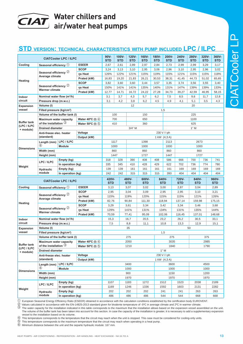
STD VERSION: TECHNICAL CHARACTERISTICS WITH PUMP INCLUDED LPC / ILPC
European Seasonal Energy Effi ciency Ratio (ESEER) obtained in accordance with the calculation conditions established by the certifi cation body EUROVENT.Values calculated in accordance with the EN-14825-2013 standard given for bivalente temperature of -5ºC in average climate and 2ºC in warmer climate. The water capacity for the installation indicated in this table corresponds to the maximum that the installation allows based on the expansion vessel assembled on the unit.
The volume of the buffer tank has been taken into account for this section. In case the capacity of the installation is greater, it is necessary to add a supplementary expansion vessel to the installation based on its volume.
This temperature corresponds to the temperature that the circuit may reach when the unit is stopped. This case must be considered for cooling-only units. This temperature corresponds to the maximum temperature that the circuit may reach when operating in a heat pump.Minimum distance between the unit and the separte hydraulic module: 167 mm.
CIATCooler LPC / ILPC 90V-STD
100V-STD
120V-STD
160V-STD
180V-STD
200V-STD
240V-STD
280V-STD
320V-STD
360V-STD
Cooling Seasonal effi ciency ESEER 2,67 2,61 2,89 2,97 2,84 2,73 2,99 2,99 3,29 3,17
Heating
Seasonal effi ciency Average climate
SCOP 3,24 3,13 3,10 2,95 3,06 2,96 3,10 2,95 2,96 3,02ŋs Heat 126% 122% 121% 115% 119% 115% 121% 115% 115% 118%Prated (kW) 16,83 19,20 21,83 26,21 30,53 38,31 41,45 44,73 51,02 65,65
Seasonal effi ciency Warmer climate
SCOP 3,82 3,60 3,60 3,44 3,57 3,35 3,74 3,56 3,55 3,40ŋs Heat 150% 141% 141% 135% 140% 131% 147% 139% 139% 133%Prated (kW) 12,77 14,71 16,72 24,22 27,28 34,73 39,27 42,59 46,95 58,15
Indoor circuit
Nominal water fl ow (m3/h) 3,1 3,7 4,3 5,7 6,2 7,5 8,5 9,6 11,7 12,8Pressure drop (m.w.c.) 3,1 4,2 3,8 6,2 4,5 4,9 4,1 5,1 3,5 4,3
Expansion vessel
Volume (l) 12 20Filled pressure (kg/cm2) 1,5
Buffer tank(LPC / ILPC + module)
Volume of the buffer tank (l) 100 150 225Maximum water capacity of the installation
Water 40ºC (l) 700 650 1100 Water 50ºC (l) 410 360 625
Drained diameter 3/4” M 1” M
Anti-freeze elec. heater (standard)
Voltage 230 V / I phOutput (kW) 1 kW (4,3 A)
Dimensions
Length (mm)
LPC / ILPC 1117 1398 2113 2673Module 1000 1000 1000 1000
Width (mm) 860 860 860 860Height (mm) 1447 1727 1447 1727
WeightLPC / ILPC
Empty (kg) 318 328 390 408 408 586 666 700 736 741In operation (kg) 335 345 410 428 429 622 702 736 774 780
Hydraulic module
Empty (kg) 139 139 161 161 161 161 169 169 169 169In operation (kg) 242 242 315 315 315 393 404 404 404 404
CIATCooler LPC / ILPC 420V-STD
480V-STD
600V-STD
640V-STD
720V-STD
840V-STD
960V-STD
Cooling Seasonal effi ciency ESEER 3,13 3,07 3,02 3,00 2,87 3,04 2,89
Heating
Seasonal effi ciency Average climate
SCOP 2,95 3,04 3,09 2,95 2,95 3,10 3,21ŋs Heat 115% 119% 120% 115% 115% 121% 126%Prated (kW) 82,76 90,84 111,30 118,94 137,14 159,98 175,15
Seasonal effi ciency Warmer climate
SCOP 3,29 3,61 3,34 3,42 3,34 3,46 3,68ŋs Heat 129% 141% 131% 134% 131% 135% 144%Prated (kW) 70,59 77,41 95,09 102,06 116,45 137,01 148,68
Indoor circuit
Nominal water fl ow (m3/h) 15,3 16,7 20,5 23,2 26,2 30,5 33,1Pressure drop (m.w.c.) 7,5 8,8 11,1 10,8 13,3 12,9 15,1
Expansion vessel
Volume (l) 35 50Filled pressure (kg/cm2) 1,5
Buffer tank(LPC / ILPC + module)
Volume of the buffer tank (l) 275 275 375Maximum water capacity of the installation
Water 40ºC (l) 2050 3035 2985 Water 50ºC (l) 1210 1840 1790
Drained diameter 1” M
Anti-freeze elec. heater (standard)
Voltage 230 V / I phOutput (kW) 1 kW (4,3 A)
Dimensions
Length (mm)
LPC / ILPC 3400 3600 4500Module 1000 1000 1000
Width (mm) 900 1150 1200Height (mm) 1970 1970 1970
WeightLPC / ILPC
Empty (kg) 1107 1183 1272 1512 1523 2038 2189In operation (kg) 1169 1246 1336 1592 1603 2131 2282
Hydraulic module
Empty (kg) 202 202 202 241 241 263 263In operation (kg) 486 486 486 544 544 668 668
Water chillers and air/water heat pumps
HEAT PUMPS - AIR CONDITIONING - REFRIGERATION - AIR HANDLING - HEAT EXCHANGE - NA 16.701 A14
CIATCooler LP
2 31
2
20
25
3
4
5
6
78
10
LP /
ILP
pres
sure
dro
p (m
.w.c
.)
Flow (m3/h)
90V-
STD
/ 100
V-ST
D12
0V-S
TD/ 1
60V-
STD
180V
-STD
/ 200
V-ST
D
240V
-STD
/ 280
V-ST
D
320V
-STD
/ 360
V-ST
D
840V
-STD
/ 960
V-ST
D
9
15
420V
-STD
/ 480
V-ST
D60
0V-S
TD
640V
-STD
/ 720
V-ST
D4 5 6 7 8 9 10 15 20 25 30 40 50 60 70
1
2
20
3
30
4
40
5
50
6
60
7
70
89
10
15
90V-
STD
/ 100
V-ST
D12
0V-S
TD/ 1
60V-
STD
180V
-STD
200V
-STD
240V
-STD
/ 280
V-ST
D
320V
-STD
/ 360
V-ST
D
840V
-STD
/ 960
V-ST
D
420V
-STD
/ 480
V-ST
D60
0V-S
TD
640V
-STD
/ 720
V-ST
D
LPC
/ IL
PC p
ress
ure
drop
(m.w
.c.)
Flow (m3/h)2 3 4 5 6 7 8 9 10 15 20 25 30 40 50 60 70
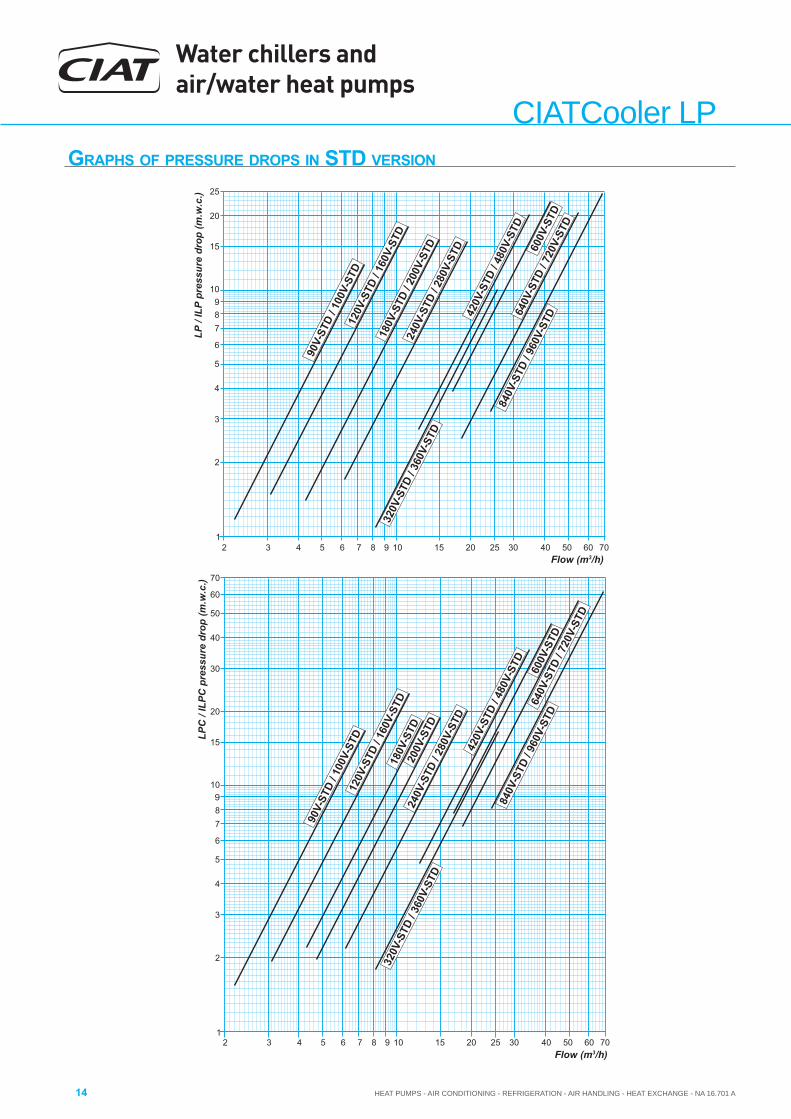
GRAPHS OF PRESSURE DROPS IN STD VERSION
HEAT PUMPS - AIR CONDITIONING - REFRIGERATION - AIR HANDLING - HEAT EXCHANGE - NA 16.701 A
Water chillers and air/water heat pumps
15
CIA
TCoo
ler L
P
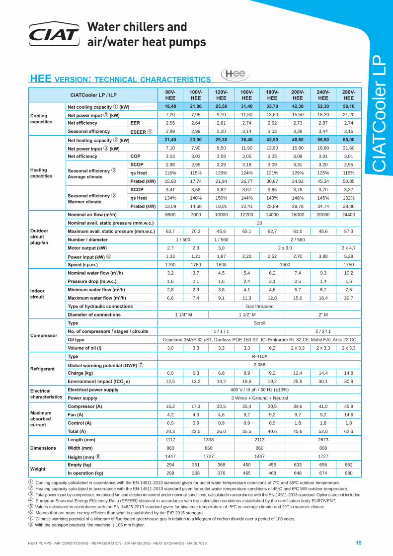
HEE VERSION: TECHNICAL CHARACTERISTICS
CIATCooler LP / ILP 90V-HEE
100V-HEE
120V-HEE
160V-HEE
180V-HEE
200V-HEE
240V-HEE
280V-HEE
Cooling capacities
Net cooling capacity (kW) 18,40 21,00 25,50 31,40 35,70 42,30 52,30 58,10
Net power input (kW) 7,20 7,95 9,10 11,50 13,60 15,50 18,20 21,20
Net effi ciency EER 2,55 2,64 2,81 2,74 2,62 2,73 2,87 2,74
Seasonal effi ciency ESEER 2,89 2,99 3,20 3,14 3,03 3,38 3,44 3,16
Heating capacities
Net heating capacity (kW) 21,40 23,90 29,30 36,40 42,50 48,60 56,60 65,00
Net power input (kW) 7,10 7,90 9,50 11,90 13,90 15,80 18,80 21,60
Net effi ciency COP 3,03 3,03 3,08 3,05 3,05 3,08 3,01 3,01
Seasonal effi ciency Average climate
SCOP 2,98 2,95 3,29 3,18 3,09 3,31 3,20 2,95
ŋs Heat 116% 115% 129% 124% 121% 129% 125% 115%
Prated (kW) 15,92 17,74 21,94 26,77 30,87 34,82 45,34 50,85
Seasonal effi ciency Warmer climate
SCOP 3,41 3,58 3,82 3,67 3,65 3,78 3,70 3,37
ŋs Heat 134% 140% 150% 144% 143% 148% 145% 132%
Prated (kW) 13,09 14,68 18,01 22,41 25,89 29,78 34,74 38,86
Outdoorcircuit plug-fan
Nominal air fl ow (m3/h) 6500 7000 10000 12200 14000 16000 20000 24400
Nominal avail. static pressure (mm.w.c.) 20
Maximum avail. static pressure (mm.w.c.) 63,7 70,3 45,6 65,1 62,7 61,0 45,6 57,3
Number / diameter 1 / 500 1 / 560 2 / 560
Motor output (kW) 2,7 2,8 3,0 2 x 3,0 2 x 4,7
Power input (kW) 1,33 1,21 1,87 2,20 2,52 2,70 3,88 5,28
Speed (r.p.m.) 1700 1780 1500 1500 1750
Indoor circuit
Nominal water fl ow (m3/h) 3,2 3,7 4,5 5,4 6,2 7,4 9,3 10,2
Pressure drop (m.w.c.) 1,6 2,1 1,6 2,4 3,1 2,5 1,4 1,6
Minimum water fl ow (m3/h) 2,8 2,9 3,8 4,1 4,6 5,7 6,7 7,5
Maximum water fl ow (m3/h) 6,6 7,4 9,1 11,3 12,8 15,0 18,4 20,7
Type of hydraulic connections Gas threaded
Diameter of connections 1 1/4” M 1 1/2” M 2” M
Compressor
Type Scroll
No. of compressors / stages / circuits 1 / 1 / 1 2 / 2 / 1
Oil type Copeland 3MAF 32 cST, Danfoss POE 160 SZ, ICI Emkarate RL 32 CF, Mobil EAL Artic 22 CC
Volume of oil (l) 3,0 3,3 3,3 3,3 6,2 2 x 3,3 2 x 3,3 2 x 3,3
Refrigerant
Type R-410A
Global warming potential (GWP) 2.088
Charge (kg) 6,0 6,3 6,8 8,9 9,2 12,4 14,4 14,8
Environment impact (tCO2 e) 12,5 13,2 14,2 18,6 19,2 25,9 30,1 30,9
Electrical characteristics
Electrical power supply 400 V / III ph / 50 Hz (±10%)
Power supply 3 Wires + Ground + Neutral
Maximum absorbed current
Compressor (A) 15,2 17,3 20,5 25,4 30,5 34,6 41,0 45,9
Fan (A) 4,2 4,3 4,6 9,2 9,2 9,2 9,2 14,6
Control (A) 0,9 0,9 0,9 0,9 0,9 1,8 1,8 1,8
Total (A) 20,3 22,5 26,0 35,5 40,6 45,6 52,0 62,3
Dimensions
Length (mm) 1117 1398 2113 2673
Width (mm) 860 860 860 860
Height (mm) 1447 1727 1447 1727
WeightEmpty (kg) 294 351 368 450 455 633 656 662
In operation (kg) 298 358 376 465 468 648 674 680
Cooling capacity calculated in accordance with the EN-14511-2013 standard given for outlet water temperature conditions of 7ºC and 35ºC outdoor temperature. Heating capacity calculated in accordance with the EN-14511-2013 standard given for outlet water temperature conditions of 45ºC and 6ºC WB outdoor temperature. Total power input by compressor, motorised fan and electronic control under nominal conditions, calculated in accordance with the EN-14511-2013 standard. Options are not included. European Seasonal Energy Effi ciency Ratio (ESEER) obtained in accordance with the calculation conditions established by the certifi cation body EUROVENT.Values calculated in accordance with the EN-14825-2013 standard given for bivalente temperature of -5ºC in average climate and 2ºC in warmer climate.Motors that are more energy effi cient than what is established by the ErP 2015 standard.Climatic warming potential of a kilogram of fl uorinated greenhouse gas in relation to a kilogram of carbon dioxide over a period of 100 years.With the transport brackets the machine is 106 mm higher.
Water chillers and air/water heat pumps
HEAT PUMPS - AIR CONDITIONING - REFRIGERATION - AIR HANDLING - HEAT EXCHANGE - NA 16.701 A16
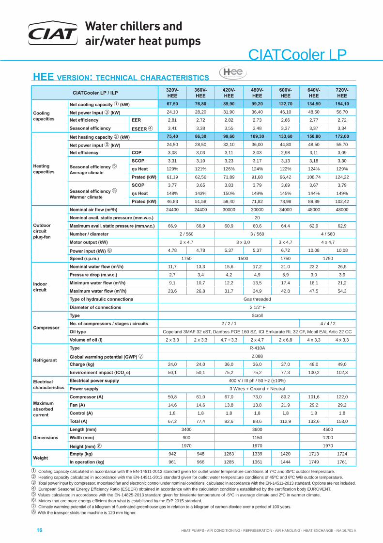
CIATCooler LPHEE VERSION: TECHNICAL CHARACTERISTICS
CIATCooler LP / ILP 320V-HEE
360V-HEE
420V-HEE
480V-HEE
600V-HEE
640V-HEE
720V-HEE
Cooling capacities
Net cooling capacity (kW) 67,50 76,80 89,90 99,20 122,70 134,50 154,10
Net power input (kW) 24,10 28,20 31,90 36,40 46,10 48,50 56,70
Net effi ciency EER 2,81 2,72 2,82 2,73 2,66 2,77 2,72
Seasonal effi ciency ESEER 3,41 3,38 3,55 3,48 3,37 3,37 3,34
Heating capacities
Net heating capacity (kW) 75,40 86,30 99,60 109,30 133,60 150,80 172,00
Net power input (kW) 24,50 28,50 32,10 36,00 44,80 48,50 55,70
Net effi ciency COP 3,08 3,03 3,11 3,03 2,98 3,11 3,09
Seasonal effi ciency Average climate
SCOP 3,31 3,10 3,23 3,17 3,13 3,18 3,30
ŋs Heat 129% 121% 126% 124% 122% 124% 129%
Prated (kW) 61,19 62,56 71,89 91,68 96,42 108,74 124,22
Seasonal effi ciency Warmer climate
SCOP 3,77 3,65 3,83 3,79 3,69 3,67 3,79
ŋs Heat 148% 143% 150% 149% 145% 144% 149%
Prated (kW) 46,83 51,58 59,40 71,82 78,98 89,89 102,42
Outdoorcircuit plug-fan
Nominal air fl ow (m3/h) 24400 24400 30000 30000 34000 48000 48000
Nominal avail. static pressure (mm.w.c.) 20
Maximum avail. static pressure (mm.w.c.) 66,9 66,9 60,9 60,6 64,4 62,9 62,9
Number / diameter 2 / 560 3 / 560 4 / 560
Motor output (kW) 2 x 4,7 3 x 3,0 3 x 4,7 4 x 4,7
Power input (kW) 4,78 4,78 5,37 5,37 6,72 10,08 10,08
Speed (r.p.m.) 1750 1500 1750 1750
Indoor circuit
Nominal water fl ow (m3/h) 11,7 13,3 15,6 17,2 21,0 23,2 26,5
Pressure drop (m.w.c.) 2,7 3,4 4,2 4,9 5,9 3,0 3,9
Minimum water fl ow (m3/h) 9,1 10,7 12,2 13,5 17,4 18,1 21,2
Maximum water fl ow (m3/h) 23,6 26,8 31,7 34,9 42,8 47,5 54,3
Type of hydraulic connections Gas threaded
Diameter of connections 2 1/2” F
Compressor
Type Scroll
No. of compressors / stages / circuits 2 / 2 / 1 4 / 4 / 2
Oil type Copeland 3MAF 32 cST, Danfoss POE 160 SZ, ICI Emkarate RL 32 CF, Mobil EAL Artic 22 CC
Volume of oil (l) 2 x 3,3 2 x 3,3 4,7 + 3,3 2 x 4,7 2 x 6,8 4 x 3,3 4 x 3,3
Refrigerant
Type R-410A
Global warming potential (GWP) 2.088
Charge (kg) 24,0 24,0 36,0 36,0 37,0 48,0 49,0
Environment impact (tCO2 e) 50,1 50,1 75,2 75,2 77,3 100,2 102,3
Electrical characteristics
Electrical power supply 400 V / III ph / 50 Hz (±10%)
Power supply 3 Wires + Ground + Neutral
Maximum absorbed current
Compressor (A) 50,8 61,0 67,0 73,0 89,2 101,6 122,0
Fan (A) 14,6 14,6 13,8 13,8 21,9 29,2 29,2
Control (A) 1,8 1,8 1,8 1,8 1,8 1,8 1,8
Total (A) 67,2 77,4 82,6 88,6 112,9 132,6 153,0
Dimensions
Length (mm) 3400 3600 4500
Width (mm) 900 1150 1200
Height (mm) 1970 1970 1970
WeightEmpty (kg) 942 948 1263 1339 1420 1713 1724
In operation (kg) 961 966 1285 1361 1444 1749 1761
Cooling capacity calculated in accordance with the EN-14511-2013 standard given for outlet water temperature conditions of 7ºC and 35ºC outdoor temperature. Heating capacity calculated in accordance with the EN-14511-2013 standard given for outlet water temperature conditions of 45ºC and 6ºC WB outdoor temperature. Total power input by compressor, motorised fan and electronic control under nominal conditions, calculated in accordance with the EN-14511-2013 standard. Options are not included. European Seasonal Energy Effi ciency Ratio (ESEER) obtained in accordance with the calculation conditions established by the certifi cation body EUROVENT.Values calculated in accordance with the EN-14825-2013 standard given for bivalente temperature of -5ºC in average climate and 2ºC in warmer climate.Motors that are more energy effi cient than what is established by the ErP 2015 standard.Climatic warming potential of a kilogram of fl uorinated greenhouse gas in relation to a kilogram of carbon dioxide over a period of 100 years.With the transpor skids the machine is 120 mm higher.
HEAT PUMPS - AIR CONDITIONING - REFRIGERATION - AIR HANDLING - HEAT EXCHANGE - NA 16.701 A
Water chillers and air/water heat pumps
17
CIA
TCoo
ler L
P
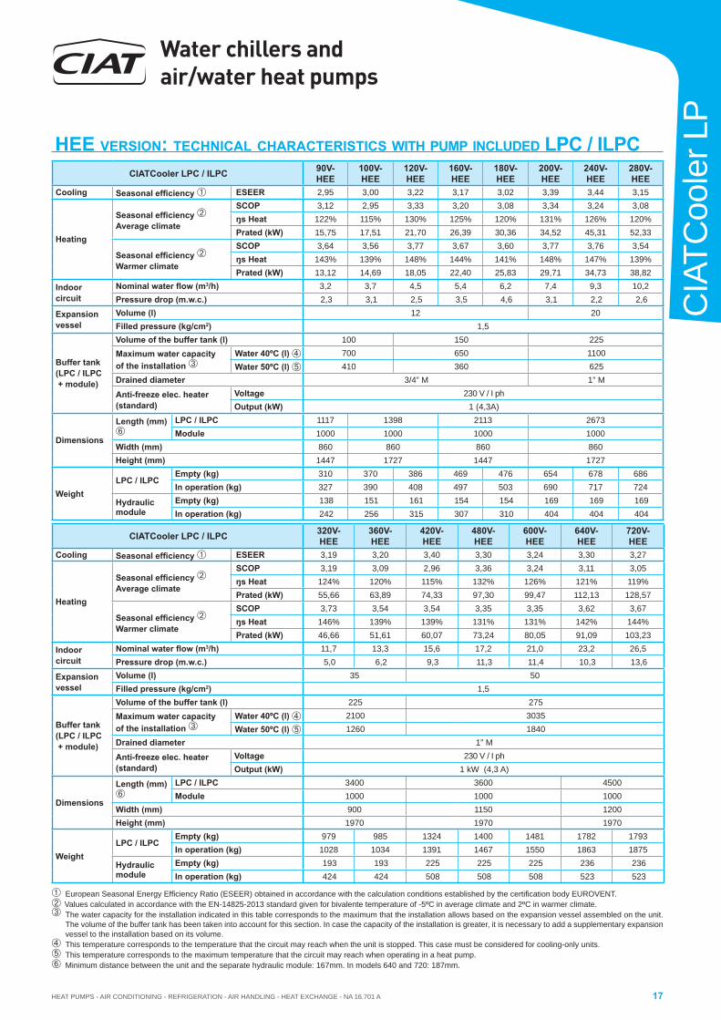
HEE VERSION: TECHNICAL CHARACTERISTICS WITH PUMP INCLUDED LPC / ILPCCIATCooler LPC / ILPC 90V-
HEE100V-HEE
120V-HEE
160V-HEE
180V-HEE
200V-HEE
240V-HEE
280V-HEE
Cooling Seasonal effi ciency ESEER 2,95 3,00 3,22 3,17 3,02 3,39 3,44 3,15
Heating
Seasonal effi ciency Average climate
SCOP 3,12 2,95 3,33 3,20 3,08 3,34 3,24 3,08ŋs Heat 122% 115% 130% 125% 120% 131% 126% 120%Prated (kW) 15,75 17,51 21,70 26,39 30,36 34,52 45,31 52,33
Seasonal effi ciency Warmer climate
SCOP 3,64 3,56 3,77 3,67 3,60 3,77 3,76 3,54ŋs Heat 143% 139% 148% 144% 141% 148% 147% 139%Prated (kW) 13,12 14,69 18,05 22,40 25,83 29,71 34,73 38,82
Indoor circuit
Nominal water fl ow (m3/h) 3,2 3,7 4,5 5,4 6,2 7,4 9,3 10,2Pressure drop (m.w.c.) 2,3 3,1 2,5 3,5 4,6 3,1 2,2 2,6
Expansion vessel
Volume (l) 12 20Filled pressure (kg/cm2) 1,5
Buffer tank(LPC / ILPC + module)
Volume of the buffer tank (l) 100 150 225Maximum water capacity of the installation
Water 40ºC (l) 700 650 1100 Water 50ºC (l) 410 360 625
Drained diameter 3/4” M 1” M
Anti-freeze elec. heater (standard)
Voltage 230 V / I phOutput (kW) 1 (4,3A)
Dimensions
Length (mm)
LPC / ILPC 1117 1398 2113 2673Module 1000 1000 1000 1000
Width (mm) 860 860 860 860Height (mm) 1447 1727 1447 1727
WeightLPC / ILPC
Empty (kg) 310 370 386 469 476 654 678 686In operation (kg) 327 390 408 497 503 690 717 724
Hydraulic module
Empty (kg) 138 151 161 154 154 169 169 169In operation (kg) 242 256 315 307 310 404 404 404
CIATCooler LPC / ILPC 320V-HEE
360V-HEE
420V-HEE
480V-HEE
600V-HEE
640V-HEE
720V-HEE
Cooling Seasonal effi ciency ESEER 3,19 3,20 3,40 3,30 3,24 3,30 3,27
Heating
Seasonal effi ciency Average climate
SCOP 3,19 3,09 2,96 3,36 3,24 3,11 3,05ŋs Heat 124% 120% 115% 132% 126% 121% 119%Prated (kW) 55,66 63,89 74,33 97,30 99,47 112,13 128,57
Seasonal effi ciency Warmer climate
SCOP 3,73 3,54 3,54 3,35 3,35 3,62 3,67ŋs Heat 146% 139% 139% 131% 131% 142% 144%Prated (kW) 46,66 51,61 60,07 73,24 80,05 91,09 103,23
Indoor circuit
Nominal water fl ow (m3/h) 11,7 13,3 15,6 17,2 21,0 23,2 26,5Pressure drop (m.w.c.) 5,0 6,2 9,3 11,3 11,4 10,3 13,6
Expansion vessel
Volume (l) 35 50Filled pressure (kg/cm2) 1,5
Buffer tank(LPC / ILPC + module)
Volume of the buffer tank (l) 225 275Maximum water capacity of the installation
Water 40ºC (l) 2100 3035 Water 50ºC (l) 1260 1840
Drained diameter 1” M
Anti-freeze elec. heater (standard)
Voltage 230 V / I phOutput (kW) 1 kW (4,3 A)
Dimensions
Length (mm)
LPC / ILPC 3400 3600 4500Module 1000 1000 1000
Width (mm) 900 1150 1200Height (mm) 1970 1970 1970
WeightLPC / ILPC
Empty (kg) 979 985 1324 1400 1481 1782 1793In operation (kg) 1028 1034 1391 1467 1550 1863 1875
Hydraulic module
Empty (kg) 193 193 225 225 225 236 236In operation (kg) 424 424 508 508 508 523 523
European Seasonal Energy Effi ciency Ratio (ESEER) obtained in accordance with the calculation conditions established by the certifi cation body EUROVENT.Values calculated in accordance with the EN-14825-2013 standard given for bivalente temperature of -5ºC in average climate and 2ºC in warmer climate. The water capacity for the installation indicated in this table corresponds to the maximum that the installation allows based on the expansion vessel assembled on the unit.
The volume of the buffer tank has been taken into account for this section. In case the capacity of the installation is greater, it is necessary to add a supplementary expansion vessel to the installation based on its volume.
This temperature corresponds to the temperature that the circuit may reach when the unit is stopped. This case must be considered for cooling-only units. This temperature corresponds to the maximum temperature that the circuit may reach when operating in a heat pump.Minimum distance between the unit and the separate hydraulic module: 167mm. In models 640 and 720: 187mm.
Water chillers and air/water heat pumps
HEAT PUMPS - AIR CONDITIONING - REFRIGERATION - AIR HANDLING - HEAT EXCHANGE - NA 16.701 A18
CIATCooler LP
2 3 4 405 50 607 8 9 10 15 20
1
2
3
4
5
6
0,6
7
0,7
8
0,8
10
3025
LP /
ILP
pres
sure
dro
p (m
.w.c
.)
Flow ( m /h)3
9
0,9
15
20
25
90V-
HEE
/ 100
V-HE
E12
0V-H
EE/ 1
60V-
HEE
/ 180
V-HE
E
200V
-HEE
240V
-HEE
/ 280
V-HE
E32
0V-H
EE/ 3
60V-
HEE
600V
-HEE
640V
-HEE
/ 720
V-HE
E42
0V-H
EE48
0V-H
EE
6
1
2
20
25
3
30
4
40
5
50
6
789
10
15
90V-
HEE
/ 100
V-HE
E12
0V-H
EE/ 1
60V-
HEE
/ 180
V-HE
E20
0V-H
EE24
0V-H
EE/ 2
80V-
HEE
320V
-HEE
/ 360
V-HE
E42
0V-H
EE/ 4
80V-
HEE
600V
-HEE
640V
-HEE
/ 720
V-HE
E
Flow (m /h)32 3 4 5 6 7 8 9 10 15 20 25 30 40 50 60
LPC
/ IL
PC p
ress
ure
drop
(m.w
.c.)
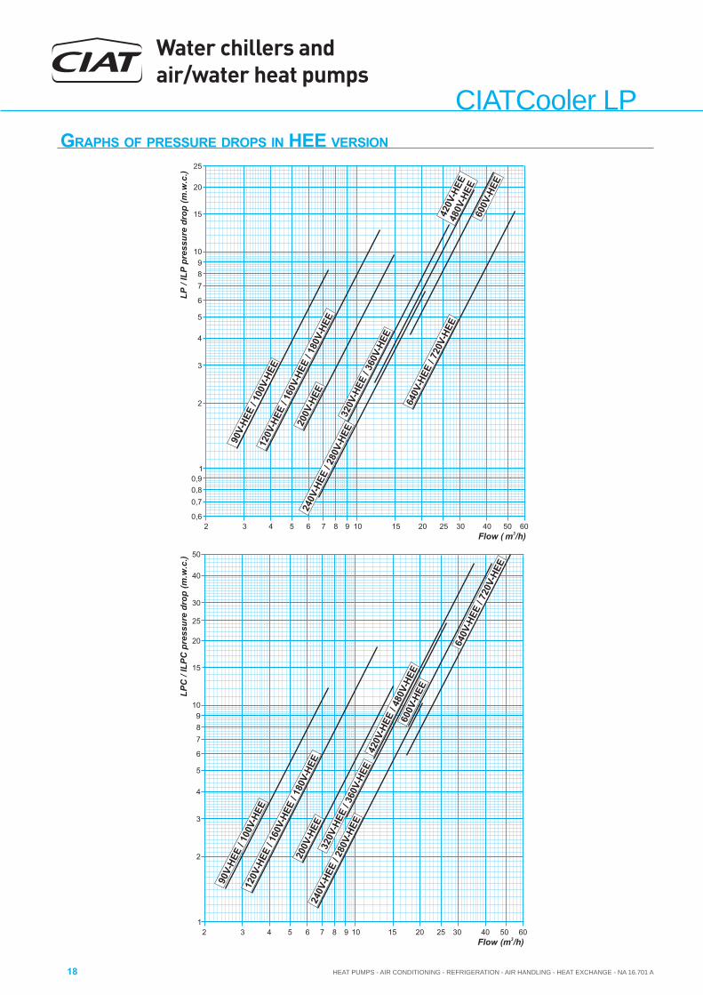
GRAPHS OF PRESSURE DROPS IN HEE VERSION
HEAT PUMPS - AIR CONDITIONING - REFRIGERATION - AIR HANDLING - HEAT EXCHANGE - NA 16.701 A
Water chillers and air/water heat pumps
19
CIA
TCoo
ler L
P
89
0,2
2
3
0,3
0,4
4
0,5
5
0,6
0,7
7
0,8
1
Pres
sure
dro
p in
the
filte
r (m
.w.c
.)
Flow (m /h)3
6
0,9
120
/ 160
/ 180
90/ 1
00
420
/ 480
/ 600
/ 640
/ 720
/ 840
/ 960
200
/ 240
/ 280
/ 320
/ 360
2 3 4 5 6 7 8 9 10 15 20 25 30 40 50 60 70
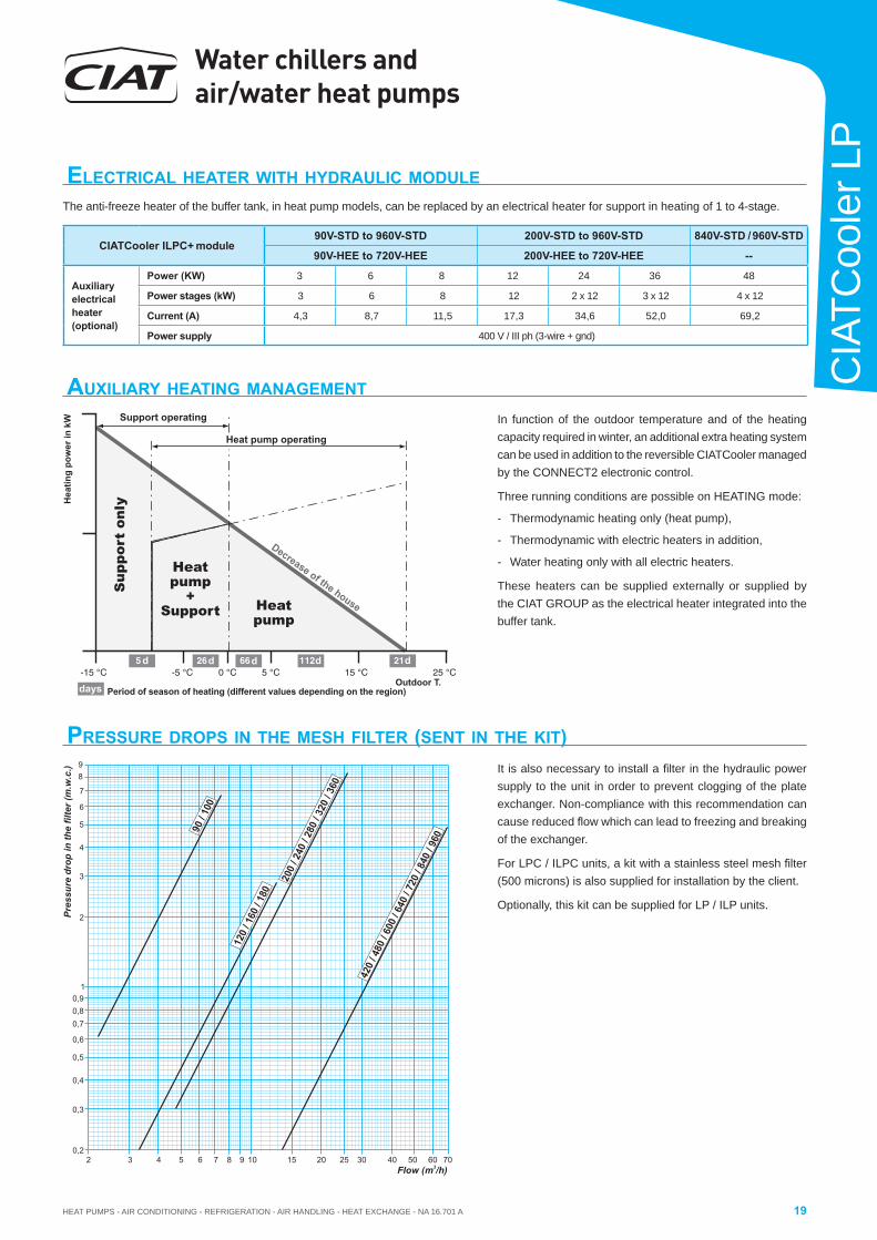
PRESSURE DROPS IN THE MESH FILTER (SENT IN THE KIT) It is also necessary to install a fi lter in the hydraulic power supply to the unit in order to prevent clogging of the plate exchanger. Non-compliance with this recommendation can cause reduced fl ow which can lead to freezing and breaking of the exchanger.
For LPC / ILPC units, a kit with a stainless steel mesh fi lter (500 microns) is also supplied for installation by the client.
Optionally, this kit can be supplied for LP / ILP units.
ELECTRICAL HEATER WITH HYDRAULIC MODULEThe anti-freeze heater of the buffer tank, in heat pump models, can be replaced by an electrical heater for support in heating of 1 to 4-stage.
AUXILIARY HEATING MANAGEMENTIn function of the outdoor temperature and of the heating capacity required in winter, an additional extra heating system can be used in addition to the reversible CIATCooler managed by the CONNECT2 electronic control.
Three running conditions are possible on HEATING mode:
- Thermodynamic heating only (heat pump),
- Thermodynamic with electric heaters in addition,
- Water heating only with all electric heaters.
These heaters can be supplied externally or supplied by the CIAT GROUP as the electrical heater integrated into the buffer tank.
Support operating
Heat pump operating
Sup
port
onl
y
Heatpump
+Support Heat
pump
Period of season of heating (different values depending on the region)
Hea
ting
pow
er in
kW
d d d d d
days
Decrease of the house
Outdoor T.
CIATCooler ILPC+ module90V-STD to 960V-STD 200V-STD to 960V-STD 840V-STD / 960V-STD
90V-HEE to 720V-HEE 200V-HEE to 720V-HEE --
Auxiliaryelectricalheater(optional)
Power (KW) 3 6 8 12 24 36 48
Power stages (kW) 3 6 8 12 2 x 12 3 x 12 4 x 12
Current (A) 4,3 8,7 11,5 17,3 34,6 52,0 69,2
Power supply 400 V / III ph (3-wire + gnd)
Water chillers and air/water heat pumps
HEAT PUMPS - AIR CONDITIONING - REFRIGERATION - AIR HANDLING - HEAT EXCHANGE - NA 16.701 A20
CIATCooler LPMINIMUM VOLUME OF WATER ADMISSIBLE IN THE INSTALLATION (COOLING MODE)
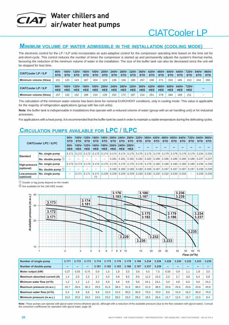
The electronic control for the LP / ILP units incorporates an auto-adaptive control for the compressor operating time based on the time set for anti-short-cycle. This control reduces the number of times the compressor is started up and permanently adjusts the system's thermal inertia, favouring the reduction of the minimum volume of water in the installation. The size of the buffer tank can also be decreased since the unit will be stopped for less time.
The calculation of the minimum water volume has been done for nominal EUROVENT conditions, only in cooling mode. This value is applicablefor the majority of refrigeration applications (group with fan-coil units).
Note: the buffer tank is indispensable in installations that operate with a reduced volume of water (group with an air handling unit) or for industrial processes.
For applications with a heat pump, it is recommended that the buffer tank be used in order to maintain a stable temperature during the defrosting cycles.
CIRCULATION PUMPS AVAILABLE FOR LPC / ILPC
1 3 4 5 7 8 9 10 15 2010
20
30
40
3025
Ava
ilabl
e pr
essu
re (m
.w.c
.)
Flow (m3/h)
3.1713.172
3.173 3.1743.181
3.1753.182
3.1763.183
3.230
2 6 40 50 7060
3.1793.186
3.233
3.1803.187
3.2323.229
3.2363.239
3.2343.237
3.235
Note: These pumps can operate with glycol water (mono-ethylene glycol), although with a reduction of the available pressure (due to the fl ow variation with glycol water). Consult the correction coeffi cients for operation with glycol water, page 38.
CIATCooler LP / ILP 90V-STD
100V-STD
120V-STD
160V-STD
180V-STD
200V-STD
240V-STD
280V-STD
320V-STD
360V-STD
420V-STD
480V-STD
600V-STD
640V-STD
720V-STD
840V-STD
960V-STD
Minimum volume (litres) 101 120 143 187 204 123 138 156 189 207 248 271 333 185 210 244 265
CIATCooler LPC / ILPC
90V-STD
100V-STD
120V-STD
160V-STD
180V-STD
200V-STD
240V-STD
280V-STD
320V-STD
360V-STD
420V-STD
480V-STD
600V-STD
640V-STD
720V-STD
840V-STD
960V-STD
90V-HEE
100V-HEE
120V-HEE
160V-HEE
180V-HEE
200V-HEE
240V-HEE
280V-HEE -- -- -- -- -- -- -- -- --
StandardNo. single pump 3.171 3.172 3.172 3.173 3.174 3.174 3.174 3.175 3.175 3.175 3.179 3.179 3.179 3.179 3.179 3.234 3.234
No. double pump -- -- -- -- -- 3.181 3.181 3.182 3.182 3.182 3.186 3.186 3.186 3.186 3.186 3.237 3.237
High-pressure(optional)
No. single pump 3.173 3.173 3.174 3.174 3.175 3.176 3.176 3.176 3.176 3.176 3.180 3.180 3.180 3.180 3.180 3.236 3.236
No. double pump -- -- -- -- -- 3.183 3.183 3.183 3.183 3.183 3.187 3.187 3.187 3.187 3.187 3.239 3.239
Low-pressure (optional)
No. single pump -- 3.171 3.171 3.171 (*)
3.229 3.229 3.229 3.229 3.230 3.230 3.232 3.232 3.233 3.233 -- 3.235 3.235
Number of single pump 3.171 3.172 3.173 3.174 3.175 3.176 3.179 3.180 3.234 3.236 3.229 3.230 3.232 3.233 3.235
Number of double pump -- -- -- 3.181 3.182 3.183 3.186 3.187 3.237 3.239 -- -- -- -- --
Motor output (kW) 0,37 0,55 0,75 0,9 1,5 1,8 3,0 3,6 5,5 7,5 0,55 0,9 1,1 1,8 3,0
Maximum absorbed current (A) 1,4 2,0 2,3 2,7 4,0 4,8 8,0 9,6 11,5 15,5 2,0 2,7 3,8 5,4 6,8
Minimum water fl ow (m3/h) 1,2 1,2 1,2 3,0 4,8 4,8 9,6 9,6 24,1 24,1 3,0 4,8 6,0 9,6 24,1
Maximum pressure (m.w.c.) 20,7 28,0 30,3 29,5 31,6 38,0 31,6 38,0 31,0 38,5 20,6 20,6 20,6 20,6 20,6
Maximum water fl ow (m3/h) 5,4 4,8 6,6 9,6 15,0 15,0 30,0 30,0 70,0 70,0 9,6 15,0 19,2 30,0 70,0
Minimum pressure (m.w.c.) 15,0 20,5 19,5 19,5 23,0 28,0 23,0 28,0 18,5 26,6 13,7 12,5 13,7 12,5 8,4
Double or lag pump depend on the model. Not available for the 160-HEE model.
CIATCooler LP / ILP 90V-HEE
100V-HEE
120V-HEE
160V-HEE
180V-HEE
200V-HEE
240V-HEE
280V-HEE
320V-HEE
360V-HEE
420V-HEE
480V-HEE
600V-HEE
640V-HEE
720V-HEE --
Minimum volume (litres) 107 132 152 189 210 129 152 172 187 214 251 278 344 183 211 --
HEAT PUMPS - AIR CONDITIONING - REFRIGERATION - AIR HANDLING - HEAT EXCHANGE - NA 16.701 A
Water chillers and air/water heat pumps
21
CIA
TCoo
ler L
P
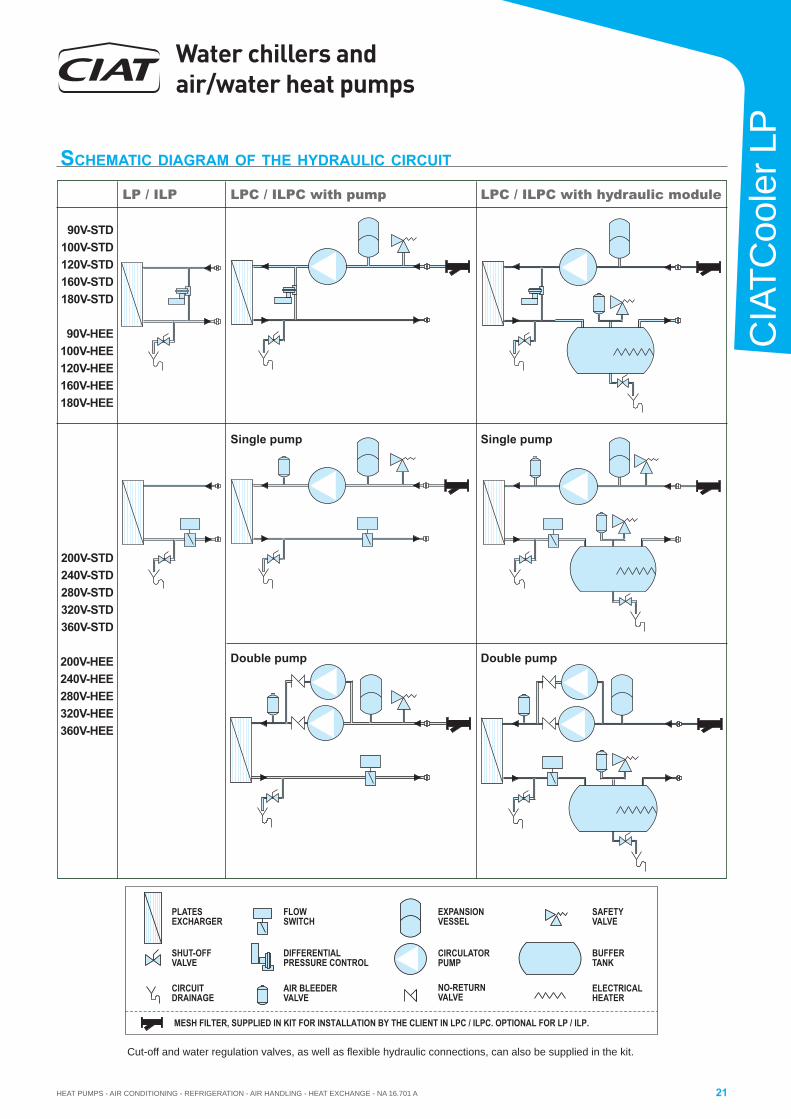
SCHEMATIC DIAGRAM OF THE HYDRAULIC CIRCUIT
LPC / ILPC with hydraulic moduleLPC / ILPC with pumpLP / ILP
Single pump Single pump
Double pump Double pump
Cut-off and water regulation valves, as well as fl exible hydraulic connections, can also be supplied in the kit.
90V-STD100V-STD120V-STD160V-STD180V-STD
90V-HEE100V-HEE120V-HEE160V-HEE180V-HEE
200V-STD240V-STD280V-STD320V-STD360V-STD
200V-HEE240V-HEE280V-HEE320V-HEE360V-HEE
MESH FILTER, SUPPLIED IN KIT FOR INSTALLATION BY THE CLIENT IN LPC / ILPC. OPTIONAL FOR LP / ILP.
DIFFERENTIALPRESSURE CONTROL
PLATESEXCHARGER
EXPANSIONVESSEL
FLOWSWITCH
SHUT-OFFVALVE
DRAINAGECIRCUIT
SAFETYVALVE
NO RETURN-VALVE
AIR BLEEDERVALVE
CIRCULATORPUMP T
BUFFERANK
ELECTRICALHEATER
Water chillers and air/water heat pumps
HEAT PUMPS - AIR CONDITIONING - REFRIGERATION - AIR HANDLING - HEAT EXCHANGE - NA 16.701 A22
CIATCooler LP
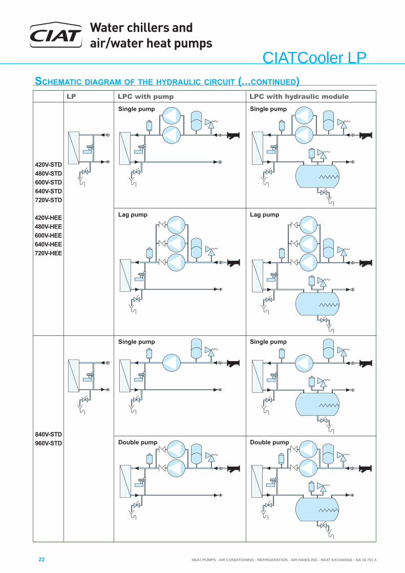
LPC with hydraulic moduleLPC with pumpLP
Single pump Single pump
Lag pump Lag pump
420V-STD480V-STD600V-STD640V-STD720V-STD
420V-HEE480V-HEE600V-HEE640V-HEE720V-HEE
Single pump Single pump
Double pump Double pump840V-STD960V-STD
SCHEMATIC DIAGRAM OF THE HYDRAULIC CIRCUIT (...CONTINUED)
HEAT PUMPS - AIR CONDITIONING - REFRIGERATION - AIR HANDLING - HEAT EXCHANGE - NA 16.701 A
Water chillers and air/water heat pumps
23
CIA
TCoo
ler L
P
LP / LPCILP / ILPC
Temperature of outlet cold
water from the evaporator in ºC
Inlet temperature of outdoor air into the condenser in °C20 25 30 35 40 44 46
Pf Pa Pf Pa Pf Pa Pf Pa Pf Pa Pf Pa Pf Pa
90V-STD
Glycol water
-7 13,6 4,5 12,9 5,0 12,0 5,5 11,1 6,0 10,3 6,6 9,5 7,1 9,1 7,4-4 15,0 4,6 14,2 5,1 13,3 5,6 12,3 6,1 11,3 6,7 10,5 7,2 10,1 7,50 17,2 4,8 16,2 5,3 15,2 5,8 14,2 6,4 13,0 7,0 12,1 7,5 11,7 7,72 18,3 4,9 17,3 5,4 16,2 5,9 15,0 6,5 13,9 7,1 13,0 7,6 12,5 7,9
Pure water
5 20,3 5,1 19,1 5,6 17,9 6,1 16,5 6,7 15,2 7,3 14,2 7,8 13,7 8,07 21,8 5,3 20,5 5,7 19,2 6,3 17,8 6,8 16,4 7,5 15,2 7,9 14,8 8,210 23,7 5,4 22,3 5,9 20,9 6,5 19,4 7,0 17,9 7,7 16,7 8,2 16,1 8,412 24,9 5,6 23,5 6,1 22,1 6,6 20,4 7,2 18,9 7,8 17,6 8,3 17,0 8,515 26,9 5,8 25,4 6,3 23,8 6,8 22,1 7,4 20,4 8,0 19,0 8,5 18,4 8,718 29,0 5,9 27,3 6,5 25,6 7,0 23,8 7,6 22,0 8,2 20,6 8,7 19,8 8,9
100V-STD
Glycol water
-7 15,5 5,2 14,9 5,8 14,1 6,3 13,4 7,0 12,5 7,7 11,7 8,3 11,3 8,6-4 17,3 5,3 16,5 5,9 15,6 6,5 14,8 7,1 13,8 7,8 13,0 8,4 12,5 8,70 20,0 5,6 19,0 6,1 18,0 6,7 16,9 7,4 15,8 8,1 14,8 8,7 14,3 9,02 21,4 5,7 20,3 6,3 19,2 6,9 18,0 7,5 16,8 8,2 15,8 8,8 15,2 9,1
Pure water
5 23,8 6,0 22,6 6,5 21,4 7,1 20,0 7,7 18,5 8,4 17,4 9,0 16,8 9,37 25,5 6,1 24,2 6,7 22,8 7,3 21,3 7,9 19,7 8,6 18,5 9,2 17,8 9,510 27,9 6,4 26,3 6,9 24,8 7,5 23,1 8,2 21,4 8,8 20,0 9,4 19,3 9,712 29,4 6,5 27,8 7,1 26,1 7,7 24,3 8,3 22,5 9,0 21,1 9,6 20,3 9,915 31,8 6,8 30,0 7,3 28,2 7,9 26,3 8,6 24,4 9,2 22,8 9,8 22,0 10,118 34,4 7,1 32,4 7,6 30,3 8,2 28,4 8,8 26,3 9,5 24,5 10,0 23,6 10,3
120V-STD
Glycol water
-7 19,1 5,7 18,1 6,3 16,9 6,9 15,7 7,6 14,4 8,4 13,4 9,0 12,9 9,3-4 21,1 5,8 20,0 6,4 18,8 7,0 17,3 7,7 15,8 8,5 14,7 9,1 14,2 9,40 23,9 6,0 22,6 6,6 21,3 7,3 19,9 8,0 18,4 8,7 17,2 9,4 16,6 9,72 25,3 6,1 24,1 6,8 22,7 7,4 21,3 8,1 19,8 8,9 18,5 9,6 17,9 9,9
Pure water
5 28,3 6,4 26,8 7,0 25,3 7,7 23,7 8,4 22,0 9,2 20,6 9,8 19,9 10,27 30,3 6,5 28,7 7,2 27,0 7,8 25,3 8,6 23,5 9,3 22,0 10,0 21,3 10,310 33,0 6,8 31,2 7,4 29,4 8,1 27,5 8,8 25,6 9,5 24,0 10,2 23,2 10,612 34,8 6,9 33,0 7,5 31,1 8,2 29,1 9,0 27,1 9,7 25,4 10,4 24,5 10,715 37,8 7,1 35,7 7,8 33,7 8,5 31,5 9,2 29,5 10,0 27,5 10,6 26,6 11,018 40,8 7,4 38,6 8,0 36,3 8,7 34,3 9,4 32,1 10,2 30,1 10,9 29,2 11,2
160V-STD
Glycol water
-7 22,6 7,0 21,2 7,7 19,9 8,6 18,5 9,5 17,2 10,6 16,1 11,5 15,5 12,0-4 27,1 7,3 25,5 8,1 24,1 8,9 22,6 9,9 21,1 10,9 19,7 11,8 19,1 12,30 30,7 7,5 29,3 8,3 27,7 9,2 26,0 10,1 24,2 11,2 22,7 12,1 21,9 12,62 32,7 7,7 31,1 8,5 29,5 9,3 27,7 10,3 25,8 11,3 24,3 12,3 23,3 12,7
Pure water
5 36,5 7,9 34,7 8,7 32,8 9,6 30,8 10,6 28,6 11,6 26,8 12,5 25,9 13,07 39,1 8,1 37,2 8,9 35,1 9,8 33,0 10,8 30,6 11,8 28,8 12,7 27,9 13,110 42,5 8,4 40,4 9,2 38,2 10,1 35,8 11,0 33,3 12,1 31,2 12,9 30,2 13,412 45,0 8,5 42,7 9,3 40,3 10,2 37,8 11,2 35,2 12,2 33,2 13,1 32,1 13,515 48,6 8,8 46,2 9,6 43,6 10,5 40,7 11,4 38,1 12,5 35,9 13,4 34,8 13,818 52,5 9,1 49,9 9,9 47,0 10,8 44,1 11,8 41,2 12,8 38,9 13,7 37,6 14,1
180V-STD
Glycol water
-7 27,0 8,6 25,5 9,4 23,9 10,4 22,2 11,5 20,4 12,7 18,9 13,7 18,2 14,2-4 29,9 8,7 28,3 9,6 26,5 10,6 24,6 11,7 22,5 12,8 20,9 13,8 20,0 14,30 34,3 9,0 32,5 9,9 30,5 10,9 28,5 12,0 26,3 13,2 24,5 14,2 23,8 14,72 36,6 9,1 34,6 10,0 32,5 11,1 30,3 12,1 28,1 13,3 26,2 14,4 25,3 14,9
Pure water
5 40,8 9,4 38,6 10,3 36,2 11,3 33,8 12,4 31,3 13,6 29,4 14,7 28,2 15,27 43,6 9,6 41,2 10,5 38,8 11,6 36,2 12,7 33,5 13,8 31,3 14,9 30,2 15,410 47,6 9,9 45,0 10,8 42,3 11,9 39,3 12,9 36,6 14,1 34,2 15,2 33,0 15,712 50,3 10,1 47,6 11,0 44,6 12,0 41,6 13,1 38,6 14,3 36,1 15,3 34,9 15,915 54,5 10,4 51,5 11,2 48,4 12,3 45,2 13,5 41,7 14,6 39,0 15,6 37,6 16,118 58,8 10,7 55,6 11,6 52,2 12,7 48,8 13,8 45,3 15,0 42,4 16,0 40,9 16,5
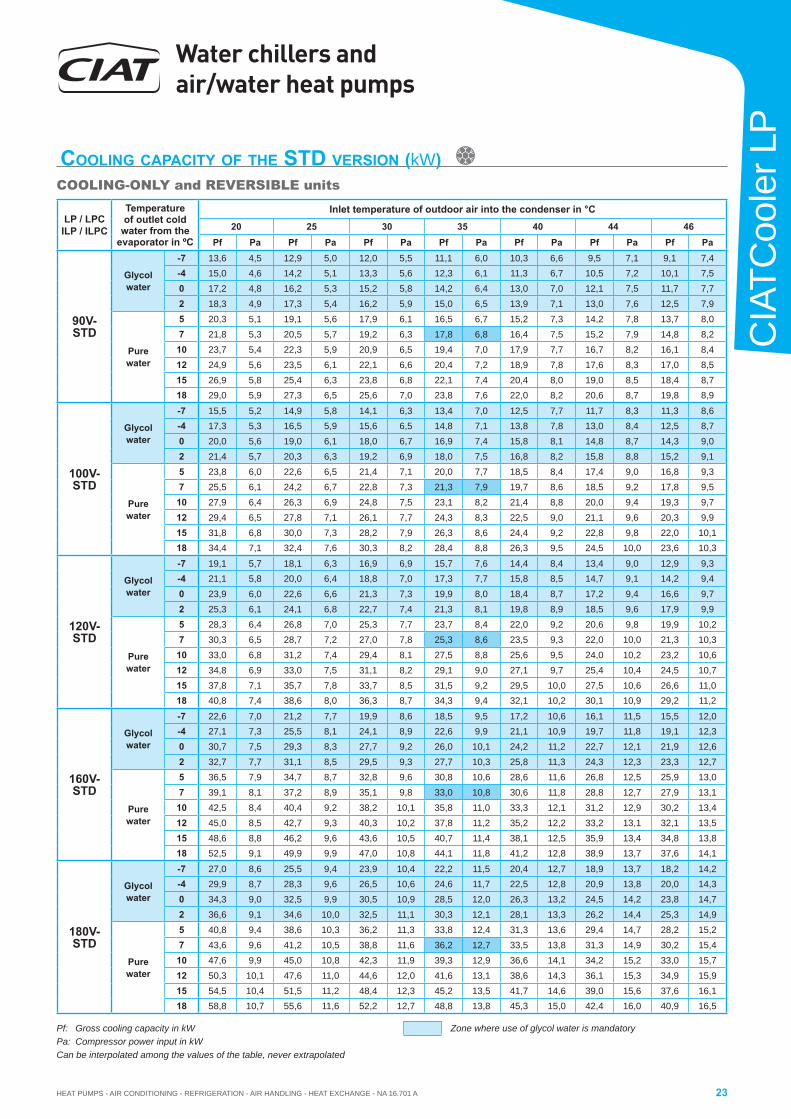
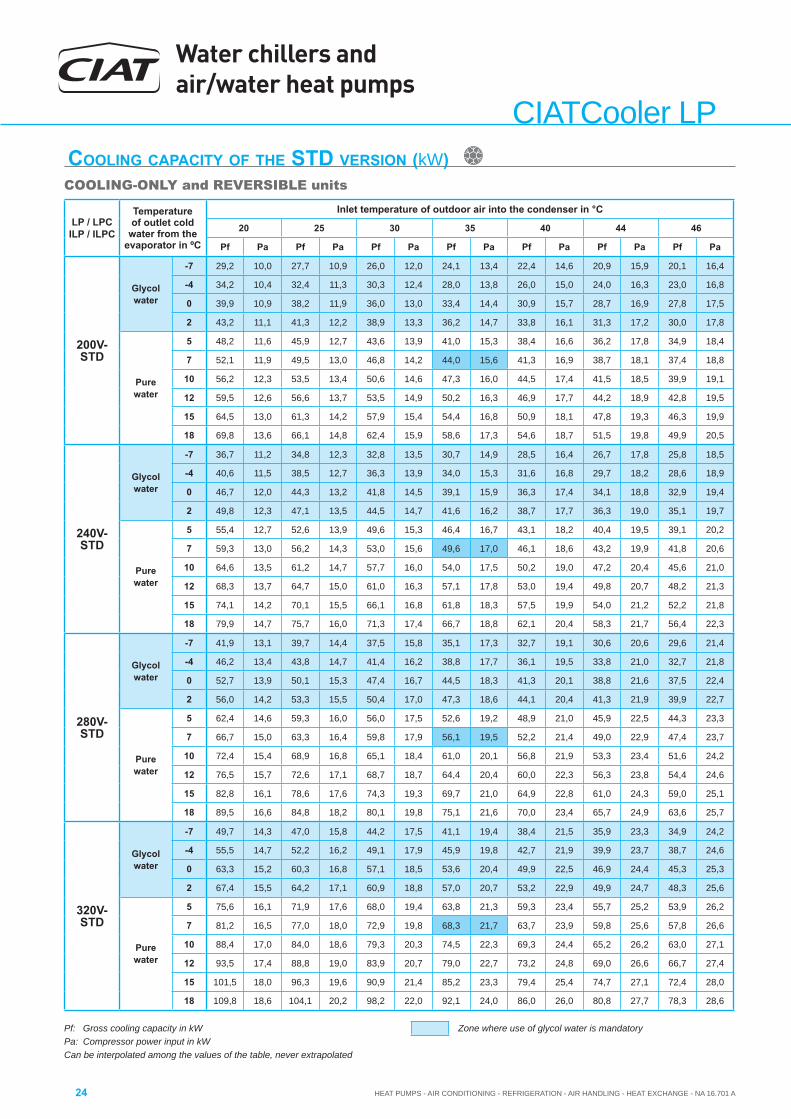
Pf: Gross cooling capacity in kWPa: Compressor power input in kWCan be interpolated among the values of the table, never extrapolated
COOLING CAPACITY OF THE STD VERSION (kW)COOLING-ONLY and REVERSIBLE units
Zone where use of glycol water is mandatory
Water chillers and air/water heat pumps
HEAT PUMPS - AIR CONDITIONING - REFRIGERATION - AIR HANDLING - HEAT EXCHANGE - NA 16.701 A24
CIATCooler LP
Pf: Gross cooling capacity in kWPa: Compressor power input in kWCan be interpolated among the values of the table, never extrapolated
COOLING CAPACITY OF THE STD VERSION (kW)COOLING-ONLY and REVERSIBLE units
Zone where use of glycol water is mandatory
LP / LPCILP / ILPC
Temperature of outlet cold
water from the evaporator in ºC
Inlet temperature of outdoor air into the condenser in °C
20 25 30 35 40 44 46
Pf Pa Pf Pa Pf Pa Pf Pa Pf Pa Pf Pa Pf Pa
200V-STD
Glycol water
-7 29,2 10,0 27,7 10,9 26,0 12,0 24,1 13,4 22,4 14,6 20,9 15,9 20,1 16,4
-4 34,2 10,4 32,4 11,3 30,3 12,4 28,0 13,8 26,0 15,0 24,0 16,3 23,0 16,8
0 39,9 10,9 38,2 11,9 36,0 13,0 33,4 14,4 30,9 15,7 28,7 16,9 27,8 17,5
2 43,2 11,1 41,3 12,2 38,9 13,3 36,2 14,7 33,8 16,1 31,3 17,2 30,0 17,8
Pure water
5 48,2 11,6 45,9 12,7 43,6 13,9 41,0 15,3 38,4 16,6 36,2 17,8 34,9 18,4
7 52,1 11,9 49,5 13,0 46,8 14,2 44,0 15,6 41,3 16,9 38,7 18,1 37,4 18,8
10 56,2 12,3 53,5 13,4 50,6 14,6 47,3 16,0 44,5 17,4 41,5 18,5 39,9 19,1
12 59,5 12,6 56,6 13,7 53,5 14,9 50,2 16,3 46,9 17,7 44,2 18,9 42,8 19,5
15 64,5 13,0 61,3 14,2 57,9 15,4 54,4 16,8 50,9 18,1 47,8 19,3 46,3 19,9
18 69,8 13,6 66,1 14,8 62,4 15,9 58,6 17,3 54,6 18,7 51,5 19,8 49,9 20,5
240V-STD
Glycol water
-7 36,7 11,2 34,8 12,3 32,8 13,5 30,7 14,9 28,5 16,4 26,7 17,8 25,8 18,5
-4 40,6 11,5 38,5 12,7 36,3 13,9 34,0 15,3 31,6 16,8 29,7 18,2 28,6 18,9
0 46,7 12,0 44,3 13,2 41,8 14,5 39,1 15,9 36,3 17,4 34,1 18,8 32,9 19,4
2 49,8 12,3 47,1 13,5 44,5 14,7 41,6 16,2 38,7 17,7 36,3 19,0 35,1 19,7
Pure water
5 55,4 12,7 52,6 13,9 49,6 15,3 46,4 16,7 43,1 18,2 40,4 19,5 39,1 20,2
7 59,3 13,0 56,2 14,3 53,0 15,6 49,6 17,0 46,1 18,6 43,2 19,9 41,8 20,6
10 64,6 13,5 61,2 14,7 57,7 16,0 54,0 17,5 50,2 19,0 47,2 20,4 45,6 21,0
12 68,3 13,7 64,7 15,0 61,0 16,3 57,1 17,8 53,0 19,4 49,8 20,7 48,2 21,3
15 74,1 14,2 70,1 15,5 66,1 16,8 61,8 18,3 57,5 19,9 54,0 21,2 52,2 21,8
18 79,9 14,7 75,7 16,0 71,3 17,4 66,7 18,8 62,1 20,4 58,3 21,7 56,4 22,3
280V-STD
Glycol water
-7 41,9 13,1 39,7 14,4 37,5 15,8 35,1 17,3 32,7 19,1 30,6 20,6 29,6 21,4
-4 46,2 13,4 43,8 14,7 41,4 16,2 38,8 17,7 36,1 19,5 33,8 21,0 32,7 21,8
0 52,7 13,9 50,1 15,3 47,4 16,7 44,5 18,3 41,3 20,1 38,8 21,6 37,5 22,4
2 56,0 14,2 53,3 15,5 50,4 17,0 47,3 18,6 44,1 20,4 41,3 21,9 39,9 22,7
Pure water
5 62,4 14,6 59,3 16,0 56,0 17,5 52,6 19,2 48,9 21,0 45,9 22,5 44,3 23,3
7 66,7 15,0 63,3 16,4 59,8 17,9 56,1 19,5 52,2 21,4 49,0 22,9 47,4 23,7
10 72,4 15,4 68,9 16,8 65,1 18,4 61,0 20,1 56,8 21,9 53,3 23,4 51,6 24,2
12 76,5 15,7 72,6 17,1 68,7 18,7 64,4 20,4 60,0 22,3 56,3 23,8 54,4 24,6
15 82,8 16,1 78,6 17,6 74,3 19,3 69,7 21,0 64,9 22,8 61,0 24,3 59,0 25,1
18 89,5 16,6 84,8 18,2 80,1 19,8 75,1 21,6 70,0 23,4 65,7 24,9 63,6 25,7
320V-STD
Glycol water
-7 49,7 14,3 47,0 15,8 44,2 17,5 41,1 19,4 38,4 21,5 35,9 23,3 34,9 24,2
-4 55,5 14,7 52,2 16,2 49,1 17,9 45,9 19,8 42,7 21,9 39,9 23,7 38,7 24,6
0 63,3 15,2 60,3 16,8 57,1 18,5 53,6 20,4 49,9 22,5 46,9 24,4 45,3 25,3
2 67,4 15,5 64,2 17,1 60,9 18,8 57,0 20,7 53,2 22,9 49,9 24,7 48,3 25,6
Pure water
5 75,6 16,1 71,9 17,6 68,0 19,4 63,8 21,3 59,3 23,4 55,7 25,2 53,9 26,2
7 81,2 16,5 77,0 18,0 72,9 19,8 68,3 21,7 63,7 23,9 59,8 25,6 57,8 26,6
10 88,4 17,0 84,0 18,6 79,3 20,3 74,5 22,3 69,3 24,4 65,2 26,2 63,0 27,1
12 93,5 17,4 88,8 19,0 83,9 20,7 79,0 22,7 73,2 24,8 69,0 26,6 66,7 27,4
15 101,5 18,0 96,3 19,6 90,9 21,4 85,2 23,3 79,4 25,4 74,7 27,1 72,4 28,0
18 109,8 18,6 104,1 20,2 98,2 22,0 92,1 24,0 86,0 26,0 80,8 27,7 78,3 28,6

HEAT PUMPS - AIR CONDITIONING - REFRIGERATION - AIR HANDLING - HEAT EXCHANGE - NA 16.701 A
Water chillers and air/water heat pumps
25
CIA
TCoo
ler L
P
Pf: Gross cooling capacity in kWPa: Compressor power input in kWCan be interpolated among the values of the table, never extrapolated
COOLING CAPACITY OF THE STD VERSION (kW)COOLING-ONLY and REVERSIBLE units
Zone where use of glycol water is mandatory
LP / LPCILP / ILPC
Temperature of outlet cold
water from the evaporator in ºC
Inlet temperature of outdoor air into the condenser in °C
20 25 30 35 40 44 46
Pf Pa Pf Pa Pf Pa Pf Pa Pf Pa Pf Pa Pf Pa
360V-STD
Glycol water
-7 53,7 17,0 51,3 18,9 48,4 20,8 44,9 23,1 41,6 25,4 38,9 27,4 37,7 28,5
-4 59,8 17,4 57,1 19,2 53,9 21,2 50,1 23,4 46,6 25,8 43,5 27,8 42,0 28,9
0 69,4 18,0 66,0 19,8 62,3 21,8 58,4 24,1 54,4 26,5 51,0 28,4 49,3 29,5
2 74,1 18,3 70,4 20,1 66,4 22,1 62,3 24,4 57,8 26,7 54,5 28,7 52,7 29,8
Pure water
5 83,2 18,9 78,9 20,7 74,5 22,7 69,9 25,1 64,9 27,3 61,0 29,3 59,1 30,4
7 89,1 19,2 84,7 21,1 79,8 23,2 74,6 25,5 69,7 27,8 65,5 29,7 63,4 30,8
10 97,3 19,8 92,3 21,7 87,1 23,8 81,6 26,0 76,1 28,4 71,6 30,3 69,3 31,4
12 103,0 20,2 97,6 22,1 92,1 24,2 86,3 26,5 80,6 28,8 75,7 30,8 73,4 31,8
15 111,7 20,8 105,9 22,8 99,5 24,9 93,6 27,2 87,3 29,4 82,2 31,5 79,6 32,5
18 120,8 21,5 114,5 23,5 108,0 25,6 101,2 27,8 94,4 30,1 88,6 32,2 86,0 33,2
420V-STD
Glycol water
-7 63,8 18,7 60,7 20,4 57,5 22,4 54,2 24,7 50,8 27,3 47,9 29,6 -- --
-4 70,8 19,1 67,4 20,9 63,9 22,9 60,3 25,2 56,5 27,8 53,5 30,2 51,9 31,4
0 81,1 19,9 77,6 21,7 73,7 23,8 69,6 26,1 65,4 28,8 61,9 31,1 60,1 32,3
2 86,9 20,2 82,8 22,1 78,6 24,2 74,3 26,6 69,8 29,2 66,1 31,6 64,2 32,8
Pure water
5 97,6 21,0 92,9 22,9 88,4 25,1 83,4 27,5 78,4 30,2 74,2 32,5 72,1 33,7
7 104,4 21,4 99,7 23,5 94,6 25,7 89,3 28,1 83,9 30,7 79,6 33,1 77,3 34,4
10 113,9 22,1 108,6 24,2 103,1 26,5 97,5 28,9 91,7 31,6 86,9 33,9 84,5 35,2
12 120,4 22,5 114,7 24,7 109,0 27,0 103,0 29,5 96,9 32,2 92,0 34,5 89,5 35,7
15 130,5 23,2 124,5 25,5 118,2 27,9 111,8 30,4 105,2 33,2 99,9 35,4 97,4 36,7
18 141,3 24,0 134,6 26,3 127,9 28,8 120,9 31,4 113,9 34,2 108,3 36,4 105,7 37,6
480V-STD
Glycol water
-7 69,8 21,2 66,2 23,3 62,6 25,4 59,2 28,1 55,6 31,1 -- -- -- --
-4 77,4 21,8 73,5 23,8 69,9 26,1 65,6 28,7 61,9 31,8 58,4 34,5 57,0 35,9
0 88,9 22,8 84,7 24,8 80,3 27,1 75,9 29,8 71,2 32,8 67,3 35,5 65,6 37,0
2 95,3 23,2 90,7 25,3 85,7 27,6 80,9 30,3 76,1 33,4 71,9 36,2 70,1 37,6
Pure water
5 107,0 24,1 101,5 26,2 96,4 28,7 91,0 31,4 85,5 34,6 80,8 37,2 78,6 38,7
7 114,4 24,7 109,0 26,9 103,3 29,4 97,6 32,2 91,4 35,2 86,7 38,0 84,4 39,5
10 124,7 25,6 118,9 27,8 112,6 30,3 106,3 33,2 99,9 36,3 94,7 39,0 92,1 40,4
12 131,9 26,2 125,4 28,5 119,0 31,0 112,3 33,9 105,6 37,0 100,4 39,8 97,5 41,1
15 143,0 27,2 136,1 29,5 128,9 32,1 121,8 35,0 114,7 38,2 108,9 40,9 106,4 42,4
18 154,8 28,3 146,9 30,6 139,5 33,3 131,6 36,2 124,0 39,4 118,1 42,1 115,6 43,6
600V-STD
Glycol water
-7 87,1 27,7 82,8 30,5 78,5 33,5 74,3 36,9 69,7 40,7 -- -- -- --
-4 96,2 28,5 91,4 31,2 87,3 34,4 81,9 37,8 77,1 41,6 72,6 44,8 71,1 46,6
0 109,7 29,8 104,9 32,6 99,7 35,7 94,0 39,2 88,0 43,0 83,2 46,2 80,9 47,9
2 117,3 30,4 112,0 33,2 105,8 36,4 100,0 39,9 93,8 43,7 88,7 47,0 86,3 48,7
Pure water
5 131,4 31,5 124,7 34,5 118,5 37,7 112,1 41,3 105,0 45,2 99,0 48,3 96,3 50,0
7 140,4 32,4 134,0 35,4 126,6 38,6 119,7 42,3 111,9 46,0 106,1 49,3 103,0 51,0
10 152,7 33,5 145,5 36,5 137,7 39,8 130,0 43,5 121,9 47,2 115,5 50,5 112,3 52,1
12 161,2 34,3 153,4 37,3 144,8 40,8 137,1 44,3 128,6 48,1 122,1 51,3 118,7 52,9
15 174,5 35,6 166,1 38,7 157,1 42,0 148,4 45,7 139,3 49,4 132,3 52,6 129,0 54,3
18 188,8 37,0 178,9 40,0 169,8 43,5 160,1 47,0 150,7 50,9 143,1 53,9 139,8 55,6
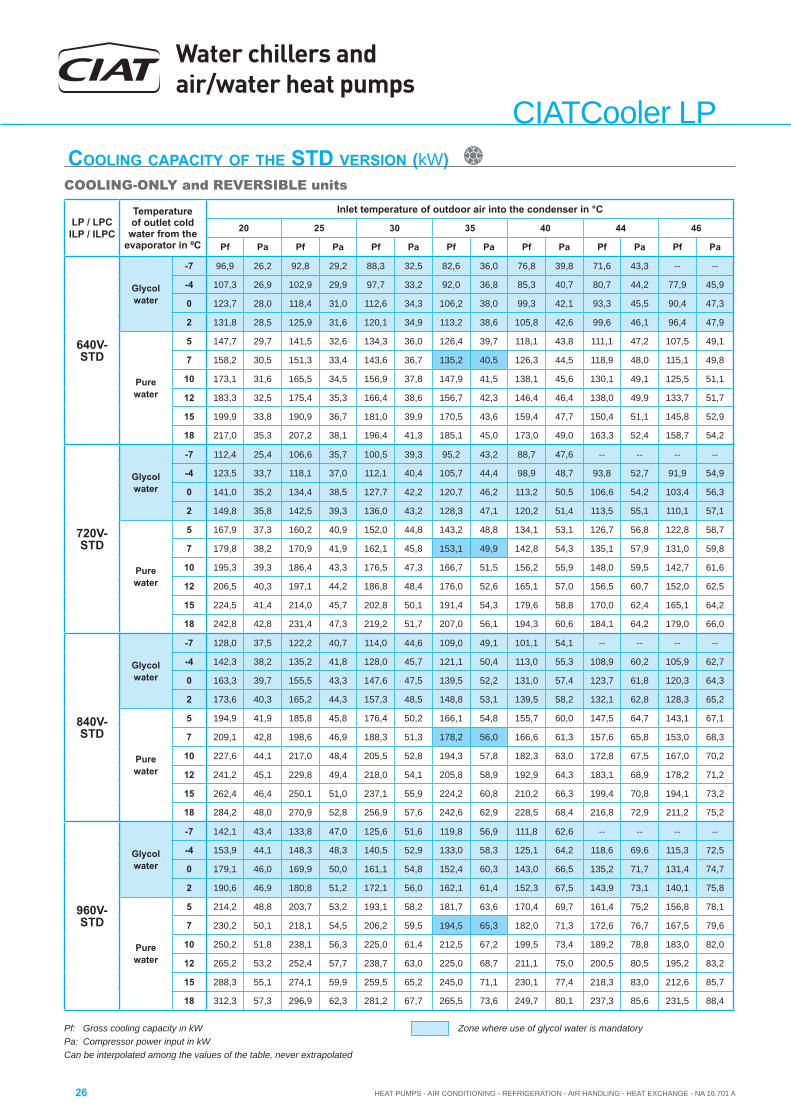
Water chillers and air/water heat pumps
HEAT PUMPS - AIR CONDITIONING - REFRIGERATION - AIR HANDLING - HEAT EXCHANGE - NA 16.701 A26
CIATCooler LP
Pf: Gross cooling capacity in kWPa: Compressor power input in kWCan be interpolated among the values of the table, never extrapolated
COOLING CAPACITY OF THE STD VERSION (kW)COOLING-ONLY and REVERSIBLE units
Zone where use of glycol water is mandatory
LP / LPCILP / ILPC
Temperature of outlet cold
water from the evaporator in ºC
Inlet temperature of outdoor air into the condenser in °C
20 25 30 35 40 44 46
Pf Pa Pf Pa Pf Pa Pf Pa Pf Pa Pf Pa Pf Pa
640V-STD
Glycol water
-7 96,9 26,2 92,8 29,2 88,3 32,5 82,6 36,0 76,8 39,8 71,6 43,3 -- --
-4 107,3 26,9 102,9 29,9 97,7 33,2 92,0 36,8 85,3 40,7 80,7 44,2 77,9 45,9
0 123,7 28,0 118,4 31,0 112,6 34,3 106,2 38,0 99,3 42,1 93,3 45,5 90,4 47,3
2 131,8 28,5 125,9 31,6 120,1 34,9 113,2 38,6 105,8 42,6 99,6 46,1 96,4 47,9
Pure water
5 147,7 29,7 141,5 32,6 134,3 36,0 126,4 39,7 118,1 43,8 111,1 47,2 107,5 49,1
7 158,2 30,5 151,3 33,4 143,6 36,7 135,2 40,5 126,3 44,5 118,9 48,0 115,1 49,8
10 173,1 31,6 165,5 34,5 156,9 37,8 147,9 41,5 138,1 45,6 130,1 49,1 125,5 51,1
12 183,3 32,5 175,4 35,3 166,4 38,6 156,7 42,3 146,4 46,4 138,0 49,9 133,7 51,7
15 199,9 33,8 190,9 36,7 181,0 39,9 170,5 43,6 159,4 47,7 150,4 51,1 145,8 52,9
18 217,0 35,3 207,2 38,1 196,4 41,3 185,1 45,0 173,0 49,0 163,3 52,4 158,7 54,2
720V-STD
Glycol water
-7 112,4 25,4 106,6 35,7 100,5 39,3 95,2 43,2 88,7 47,6 -- -- -- --
-4 123,5 33,7 118,1 37,0 112,1 40,4 105,7 44,4 98,9 48,7 93,8 52,7 91,9 54,9
0 141,0 35,2 134,4 38,5 127,7 42,2 120,7 46,2 113,2 50,5 106,6 54,2 103,4 56,3
2 149,8 35,8 142,5 39,3 136,0 43,2 128,3 47,1 120,2 51,4 113,5 55,1 110,1 57,1
Pure water
5 167,9 37,3 160,2 40,9 152,0 44,8 143,2 48,8 134,1 53,1 126,7 56,8 122,8 58,7
7 179,8 38,2 170,9 41,9 162,1 45,8 153,1 49,9 142,8 54,3 135,1 57,9 131,0 59,8
10 195,3 39,3 186,4 43,3 176,5 47,3 166,7 51,5 156,2 55,9 148,0 59,5 142,7 61,6
12 206,5 40,3 197,1 44,2 186,8 48,4 176,0 52,6 165,1 57,0 156,5 60,7 152,0 62,5
15 224,5 41,4 214,0 45,7 202,8 50,1 191,4 54,3 179,6 58,8 170,0 62,4 165,1 64,2
18 242,8 42,8 231,4 47,3 219,2 51,7 207,0 56,1 194,3 60,6 184,1 64,2 179,0 66,0
840V-STD
Glycol water
-7 128,0 37,5 122,2 40,7 114,0 44,6 109,0 49,1 101,1 54,1 -- -- -- --
-4 142,3 38,2 135,2 41,8 128,0 45,7 121,1 50,4 113,0 55,3 108,9 60,2 105,9 62,7
0 163,3 39,7 155,5 43,3 147,6 47,5 139,5 52,2 131,0 57,4 123,7 61,8 120,3 64,3
2 173,6 40,3 165,2 44,3 157,3 48,5 148,8 53,1 139,5 58,2 132,1 62,8 128,3 65,2
Pure water
5 194,9 41,9 185,8 45,8 176,4 50,2 166,1 54,8 155,7 60,0 147,5 64,7 143,1 67,1
7 209,1 42,8 198,6 46,9 188,3 51,3 178,2 56,0 166,6 61,3 157,6 65,8 153,0 68,3
10 227,6 44,1 217,0 48,4 205,5 52,8 194,3 57,8 182,3 63,0 172,8 67,5 167,0 70,2
12 241,2 45,1 229,8 49,4 218,0 54,1 205,8 58,9 192,9 64,3 183,1 68,9 178,2 71,2
15 262,4 46,4 250,1 51,0 237,1 55,9 224,2 60,8 210,2 66,3 199,4 70,8 194,1 73,2
18 284,2 48,0 270,9 52,8 256,9 57,6 242,6 62,9 228,5 68,4 216,8 72,9 211,2 75,2
960V-STD
Glycol water
-7 142,1 43,4 133,8 47,0 125,6 51,6 119,8 56,9 111,8 62,6 -- -- -- --
-4 153,9 44,1 148,3 48,3 140,5 52,9 133,0 58,3 125,1 64,2 118,6 69,6 115,3 72,5
0 179,1 46,0 169,9 50,0 161,1 54,8 152,4 60,3 143,0 66,5 135,2 71,7 131,4 74,7
2 190,6 46,9 180,8 51,2 172,1 56,0 162,1 61,4 152,3 67,5 143,9 73,1 140,1 75,8
Pure water
5 214,2 48,8 203,7 53,2 193,1 58,2 181,7 63,6 170,4 69,7 161,4 75,2 156,8 78,1
7 230,2 50,1 218,1 54,5 206,2 59,5 194,5 65,3 182,0 71,3 172,6 76,7 167,5 79,6
10 250,2 51,8 238,1 56,3 225,0 61,4 212,5 67,2 199,5 73,4 189,2 78,8 183,0 82,0
12 265,2 53,2 252,4 57,7 238,7 63,0 225,0 68,7 211,1 75,0 200,5 80,5 195,2 83,2
15 288,3 55,1 274,1 59,9 259,5 65,2 245,0 71,1 230,1 77,4 218,3 83,0 212,6 85,7
18 312,3 57,3 296,9 62,3 281,2 67,7 265,5 73,6 249,7 80,1 237,3 85,6 231,5 88,4

HEAT PUMPS - AIR CONDITIONING - REFRIGERATION - AIR HANDLING - HEAT EXCHANGE - NA 16.701 A
Water chillers and air/water heat pumps
27
CIA
TCoo
ler L
P
Pc: Gross heating capacity in kWPa: Compressor power input in kWCan be interpolated among the values of the table, never extrapolated Variation of the relative humidity for the calculations: -20ºC 95%RH / +7ºC 85%RH / +27ºC 50%RH
ILP / ILPCInlet temperature of outdoor air into the
evaporator in ºC DB
Temperature of outlet hot water from the condenser in ºC30 35 40 45 50 55
Pc Pa Pc Pa Pc Pa Pc Pa Pc Pa Pc Pa
90V-STD
-15 12,5 4,4 12,5 4,9 12,3 5,4 12,2 6,1 -- -- -- ---12 13,6 4,4 13,6 4,9 13,4 5,5 13,1 6,1 -- -- -- ---10 14,4 4,5 14,3 5,0 14,1 5,5 13,8 6,1 -- -- -- ---5 16,8 4,5 16,6 5,0 16,3 5,6 16,0 6,2 15,7 6,9 -- --0 19,3 4,6 19,0 5,1 18,7 5,6 18,2 6,2 17,8 7,0 17,2 7,85 21,7 4,7 21,4 5,2 21,0 5,7 20,7 6,3 20,2 7,0 19,5 7,87 22,7 4,7 22,4 5,2 22,0 5,7 21,6 6,3 21,1 7,0 20,5 7,810 24,4 4,7 23,9 5,2 23,5 5,8 23,0 6,4 22,5 7,1 21,7 7,915 27,4 4,8 26,7 5,3 26,1 5,8 25,5 6,4 25,0 7,1 24,3 7,920 29,9 4,9 29,3 5,4 28,6 5,9 27,9 6,5 27,1 7,2 26,3 8,0
100V-STD
-15 14,6 5,3 14,6 5,8 14,4 6,4 14,4 7,2 -- -- -- ---12 15,9 5,3 16,0 5,8 15,9 6,5 15,7 7,2 -- -- -- ---10 17,1 5,3 16,9 5,9 16,8 6,5 16,6 7,3 -- -- -- ---5 19,8 5,4 19,6 6,0 19,5 6,6 19,2 7,3 19,0 8,1 -- --0 22,7 5,5 22,5 6,1 22,3 6,7 21,9 7,4 21,3 8,2 20,8 9,15 25,8 5,6 25,4 6,2 25,1 6,8 24,6 7,5 24,0 8,3 23,4 9,27 27,2 5,6 26,8 6,2 26,4 6,8 25,9 7,6 25,4 8,3 24,7 9,2
10 29,1 5,7 28,6 6,3 28,1 6,9 27,5 7,6 26,9 8,4 26,3 9,315 32,4 5,8 31,8 6,4 31,2 7,0 30,5 7,7 29,8 8,5 29,0 9,420 35,7 6,0 35,0 6,5 34,2 7,1 33,3 7,8 32,4 8,6 31,5 9,5
120V-STD
-15 17,4 5,8 17,2 6,4 17,0 7,1 16,8 8,0 -- -- -- ---12 18,9 5,8 18,7 6,4 18,5 7,2 18,2 8,0 -- -- -- ---10 20,0 5,9 19,8 6,5 19,6 7,2 19,3 8,0 -- -- -- ---5 23,0 6,0 22,7 6,6 22,3 7,3 22,0 8,1 21,7 9,0 -- --0 26,3 6,0 25,9 6,7 25,5 7,4 25,1 8,2 24,7 9,1 24,2 10,15 29,7 6,1 29,2 6,8 28,6 7,5 28,1 8,3 27,5 9,2 26,9 10,27 31,1 6,2 30,5 6,8 30,0 7,6 29,5 8,4 28,9 9,2 28,3 10,2
10 33,5 6,2 32,7 6,9 32,1 7,6 31,4 8,5 30,7 9,3 30,0 10,315 37,3 6,4 36,4 7,0 35,6 7,7 34,8 8,6 34,0 9,4 33,1 10,420 41,0 6,4 40,0 7,1 39,0 7,8 37,9 8,7 37,0 9,5 35,9 10,4
160V-STD
-15 21,9 7,6 21,7 8,5 21,5 9,5 21,2 10,8 -- -- -- ---12 24,1 7,7 23,9 8,5 23,7 9,6 23,5 10,8 -- -- -- ---10 25,4 7,7 25,2 8,6 25,0 9,6 24,8 10,8 -- -- -- ---5 29,5 7,8 29,0 8,6 28,6 9,7 28,3 10,9 27,7 12,1 -- --0 33,6 7,9 33,1 8,7 32,5 9,7 32,2 10,9 31,7 12,2 31,2 13,75 38,2 8,0 37,5 8,8 36,7 9,8 35,8 11,0 35,2 12,2 34,8 13,77 40,1 8,0 39,4 8,9 38,8 9,9 38,0 11,0 37,3 12,2 36,6 13,710 43,1 8,1 42,3 8,9 41,5 9,9 40,6 11,0 39,7 12,3 38,7 13,715 48,2 8,2 47,2 9,1 46,1 10,0 45,1 11,1 43,9 12,3 42,7 13,820 53,1 8,3 51,9 9,2 50,7 10,1 49,4 11,2 47,9 12,4 46,6 13,9
180V-STD
-15 25,1 8,9 24,9 9,9 24,9 11,1 24,8 12,2 -- -- -- ---12 27,3 8,9 27,0 9,9 26,9 11,1 26,8 12,2 -- -- -- ---10 29,0 8,9 28,6 9,9 28,4 11,1 28,2 12,2 -- -- -- ---5 33,2 8,9 32,6 10,0 32,2 11,2 31,8 12,2 31,5 13,6 -- --0 37,9 8,9 37,3 10,0 36,7 11,2 36,0 12,3 35,4 13,7 34,7 15,25 42,8 9,0 42,0 10,0 41,1 11,2 40,4 12,3 39,5 13,7 38,7 15,37 44,8 9,0 43,9 10,1 43,1 11,3 42,4 12,3 41,3 13,7 40,2 15,310 47,9 9,0 47,1 10,1 46,1 11,3 45,1 12,4 44,1 13,8 43,0 15,315 53,5 9,1 52,4 10,1 51,2 11,3 50,1 12,4 48,7 13,8 47,3 15,420 58,7 9,1 57,4 10,2 56,0 11,4 54,8 12,5 53,0 13,9 51,5 15,4
HEATING CAPACITY OF THE STD VERSION (kW)REVERSIBLE units
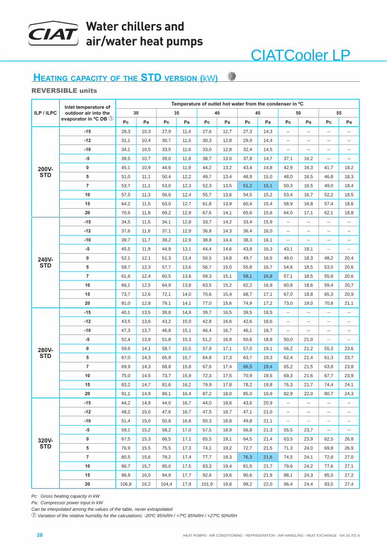
Water chillers and air/water heat pumps
HEAT PUMPS - AIR CONDITIONING - REFRIGERATION - AIR HANDLING - HEAT EXCHANGE - NA 16.701 A28
CIATCooler LP
Pc: Gross heating capacity in kWPa: Compressor power input in kWCan be interpolated among the values of the table, never extrapolated Variation of the relative humidity for the calculations: -20ºC 95%RH / +7ºC 85%RH / +27ºC 50%RH
HEATING CAPACITY OF THE STD VERSION (kW)REVERSIBLE units
ILP / ILPCInlet temperature of outdoor air into the
evaporator in ºC DB
Temperature of outlet hot water from the condenser in ºC
30 35 40 45 50 55
Pc Pa Pc Pa Pc Pa Pc Pa Pc Pa Pc Pa
200V-STD
-15 28,3 10,3 27,9 11,4 27,6 12,7 27,3 14,3 -- -- -- --
-12 31,1 10,4 30,7 11,5 30,3 12,8 29,9 14,4 -- -- -- --
-10 34,1 10,5 33,5 11,6 33,0 12,8 32,4 14,5 -- -- -- --
-5 39,5 10,7 39,0 11,8 38,7 13,0 37,8 14,7 37,1 16,2 -- --
0 45,1 10,9 44,6 11,9 44,2 13,2 43,4 14,8 42,9 16,3 41,7 18,2
5 51,0 11,1 50,4 12,2 49,7 13,4 48,9 15,0 48,0 16,5 46,8 18,3
7 53,7 11,1 53,0 12,3 52,3 13,5 51,2 15,1 50,3 16,5 49,0 18,4
10 57,5 11,3 56,6 12,4 55,7 13,6 54,5 15,2 53,4 16,7 52,2 18,5
15 64,2 11,5 63,0 12,7 61,8 13,9 60,4 15,4 58,9 16,8 57,4 18,6
20 70,6 11,8 69,2 12,9 67,6 14,1 65,6 15,6 64,0 17,1 62,1 18,8
240V-STD
-15 34,5 11,5 34,1 12,8 33,7 14,2 33,4 15,9 -- -- -- --
-12 37,6 11,6 37,1 12,9 36,8 14,3 36,4 16,0 -- -- -- --
-10 39,7 11,7 39,2 12,9 38,8 14,4 38,3 16,1 -- -- -- --
-5 45,5 11,9 44,9 13,1 44,4 14,6 43,8 16,3 43,1 18,1 -- --
0 52,1 12,1 51,3 13,4 50,5 14,8 49,7 16,5 49,0 18,3 48,2 20,4
5 58,7 12,3 57,7 13,6 56,7 15,0 55,8 16,7 54,6 18,5 53,5 20,6
7 61,6 12,4 60,5 13,6 59,3 15,1 58,1 16,8 57,1 18,5 55,8 20,6
10 66,1 12,5 64,9 13,8 63,5 15,2 62,2 16,9 60,8 18,6 59,4 20,7
15 73,7 12,6 72,1 14,0 70,6 15,4 68,7 17,1 67,0 18,8 65,3 20,9
20 81,0 12,8 79,1 14,1 77,0 15,6 74,9 17,2 73,0 19,0 70,8 21,1
280V-STD
-15 40,1 13,5 39,8 14,9 39,7 16,5 39,5 18,5 -- -- -- --
-12 43,5 13,6 43,2 15,0 42,8 16,6 42,6 18,6 -- -- -- --
-10 47,3 13,7 46,8 15,1 46,4 16,7 46,1 18,7 -- -- -- --
-5 52,4 13,9 51,8 15,3 51,2 16,9 50,6 18,9 50,0 21,0 -- --
0 59,6 14,1 58,7 15,5 57,9 17,1 57,0 19,1 56,2 21,2 55,3 23,6
5 67,0 14,3 65,9 15,7 64,8 17,3 63,7 19,3 62,4 21,4 61,3 23,7
7 69,9 14,3 68,8 15,8 67,6 17,4 66,5 19,4 65,2 21,5 63,8 23,8
10 75,0 14,5 73,7 15,9 72,3 17,5 70,9 19,5 69,3 21,6 67,7 23,9
15 83,2 14,7 81,6 16,2 79,9 17,8 78,2 19,8 76,3 21,7 74,4 24,1
20 91,1 14,9 89,1 16,4 87,2 18,0 85,0 19,9 82,9 22,0 80,7 24,3
320V-STD
-15 44,2 14,9 44,0 16,7 44,0 18,6 43,6 20,9 -- -- -- --
-12 48,2 15,0 47,6 16,7 47,5 18,7 47,1 21,0 -- -- -- --
-10 51,4 15,0 50,8 16,8 50,3 18,8 49,8 21,1 -- -- -- --
-5 59,1 15,2 58,2 17,0 57,5 18,9 56,8 21,3 55,5 23,7 -- --
0 67,5 15,3 66,5 17,1 65,5 19,1 64,5 21,4 63,5 23,9 62,5 26,8
5 76,9 15,5 75,5 17,3 74,1 19,2 72,7 21,5 71,3 24,0 69,8 26,9
7 80,5 15,6 79,2 17,4 77,7 19,3 76,3 21,6 74,5 24,1 72,8 27,0
10 86,7 15,7 85,0 17,5 83,3 19,4 81,5 21,7 79,6 24,2 77,6 27,1
15 96,9 16,0 94,9 17,7 92,6 19,6 90,6 21,9 88,1 24,3 85,5 27,2
20 106,8 16,2 104,4 17,9 101,9 19,8 99,2 22,0 96,4 24,4 93,5 27,4
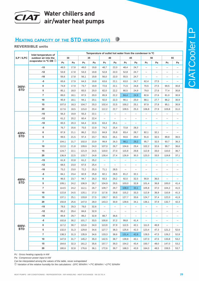
HEAT PUMPS - AIR CONDITIONING - REFRIGERATION - AIR HANDLING - HEAT EXCHANGE - NA 16.701 A
Water chillers and air/water heat pumps
29
CIA
TCoo
ler L
P
Pc: Gross heating capacity in kWPa: Compressor power input in kWCan be interpolated among the values of the table, never extrapolated Variation of the relative humidity for the calculations: -20ºC 95%RH / +7ºC 85%RH / +27ºC 50%RH
HEATING CAPACITY OF THE STD VERSION (kW)REVERSIBLE units
ILP / ILPCInlet temperature of outdoor air into the
evaporator in ºC DB
Temperature of outlet hot water from the condenser in ºC
30 35 40 45 50 55
Pc Pa Pc Pa Pc Pa Pc Pa Pc Pa Pc Pa
360V-STD
-15 49,5 17,8 49,0 19,8 48,7 22,0 48,4 24,7 -- -- -- --
-12 53,9 17,8 53,3 19,8 52,8 22,0 52,8 24,7 -- -- -- --
-10 56,6 17,8 56,1 19,8 56,0 22,0 55,5 24,7 -- -- -- --
-5 65,6 17,9 64,3 19,8 63,6 22,1 63,0 24,7 62,4 27,5 -- --
0 74,9 17,9 73,7 19,9 72,6 22,1 71,5 24,8 70,5 27,5 69,5 30,8
5 85,1 18,0 83,5 20,0 82,0 22,2 80,5 24,9 79,0 27,6 77,4 30,8
7 89,0 18,1 87,5 20,0 85,9 22,2 84,4 24,9 82,6 27,6 81,0 30,9
10 95,9 18,1 94,1 20,1 92,0 22,3 90,1 25,0 88,1 27,7 86,2 30,9
15 107,0 18,3 104,7 20,3 102,4 22,5 100,2 25,1 97,9 27,8 95,1 30,9
20 117,6 18,5 115,0 20,4 112,2 22,7 109,5 25,3 106,8 27,9 103,8 31,0
420V-STD
-15 56,3 19,9 55,3 22,1 -- -- -- -- -- -- -- --
-12 61,2 20,2 60,4 22,4 -- -- -- -- -- -- -- --
-10 65,5 20,3 64,4 22,6 63,4 25,1 -- -- -- -- -- --
-5 76,7 20,6 75,5 22,9 74,2 25,4 72,8 28,3 -- -- -- --
0 87,9 21,1 86,2 23,3 84,9 25,8 83,4 28,7 82,1 32,1 -- --
5 99,5 21,5 97,4 23,7 95,5 26,1 93,6 29,0 91,6 32,5 89,8 36,5
7 104,1 21,7 102,0 23,9 99,9 26,3 98,1 29,2 95,7 32,5 93,7 36,3
10 112,0 21,8 109,6 24,0 107,0 26,7 104,6 29,4 102,2 32,6 99,7 36,6
15 124,7 22,1 121,9 24,5 119,0 27,0 115,9 29,8 112,9 33,0 110,0 36,7
20 136,9 22,5 133,7 24,8 130,4 27,4 126,9 30,3 123,3 33,5 119,8 37,1
480V-STD
-15 61,9 22,8 61,2 25,2 -- -- -- -- -- -- -- --
-12 68,5 23,0 67,5 25,4 -- -- -- -- -- -- -- --
-10 73,2 23,0 72,2 25,3 71,1 28,5 -- -- -- -- -- --
-5 84,1 23,4 82,9 25,8 82,1 28,5 81,2 32,1 -- -- -- --
0 96,5 23,7 94,7 26,3 93,3 29,2 92,0 32,5 90,9 36,5 -- --
5 109,1 24,2 106,9 26,7 104,9 29,5 103,0 32,8 101,4 36,8 100,0 41,4
7 114,5 24,2 112,1 26,7 109,7 29,7 108,0 33,1 105,8 37,0 104,2 41,5
10 122,8 24,5 120,1 27,0 117,6 29,8 115,2 33,3 112,9 36,9 110,9 41,3
15 137,1 25,1 133,8 27,5 130,7 30,3 127,7 33,6 124,7 37,4 122,0 41,9
20 150,8 25,6 147,0 28,0 143,3 30,9 139,6 34,1 136,1 37,9 132,7 42,3
600V-STD
-15 78,5 29,3 78,0 32,6 -- -- -- -- -- -- -- --
-12 85,2 29,4 84,6 32,9 -- -- -- -- -- -- -- --
-10 89,9 29,7 89,2 32,8 88,7 36,6 -- -- -- -- -- --
-5 102,8 30,2 101,7 33,5 100,6 37,2 99,8 41,4 -- -- -- --
0 117,2 30,7 115,6 34,0 113,9 37,9 112,5 42,1 111,0 46,9 -- --
5 132,0 31,3 129,8 34,6 127,7 38,3 125,6 42,3 123,4 47,3 121,2 52,6
7 138,3 31,3 135,9 34,6 133,3 38,6 131,4 42,9 128,5 47,5 126,2 52,8
10 147,9 31,7 145,2 35,0 142,5 38,7 139,8 43,1 137,0 47,5 133,8 53,2
15 164,6 32,3 161,2 35,6 157,7 39,3 154,2 43,4 150,7 48,0 147,0 53,2
20 180,6 32,8 176,6 36,1 172,6 39,7 168,3 43,9 164,0 48,5 159,5 53,7
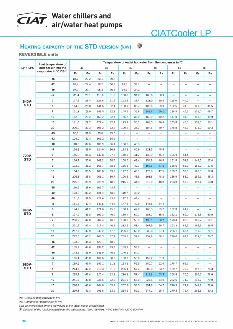
Water chillers and air/water heat pumps
HEAT PUMPS - AIR CONDITIONING - REFRIGERATION - AIR HANDLING - HEAT EXCHANGE - NA 16.701 A30
CIATCooler LP
Pc: Gross heating capacity in kWPa: Compressor power input in kWCan be interpolated among the values of the table, never extrapolated Variation of the relative humidity for the calculations: -20ºC 95%RH / +7ºC 85%RH / +27ºC 50%RH
HEATING CAPACITY OF THE STD VERSION (kW)REVERSIBLE units
ILP / ILPCInlet temperature of outdoor air into the
evaporator in ºC DB
Temperature of outlet hot water from the condenser in ºC
30 35 40 45 50 55
Pc Pa Pc Pa Pc Pa Pc Pa Pc Pa Pc Pa
640V-STD
-15 84,0 27,2 83,1 30,2 -- -- -- -- -- -- -- --
-12 91,4 27,4 90,7 30,6 89,6 34,1 -- -- -- -- -- --
-10 97,0 27,7 95,8 30,8 94,7 34,3 -- -- -- -- -- --
-5 111,4 28,1 110,0 31,3 108,3 34,9 106,6 38,9 -- -- -- --
0 127,5 28,4 125,6 31,8 123,5 35,4 121,0 39,5 118,6 44,0 -- --
5 144,2 28,8 141,6 32,1 138,9 35,7 135,6 39,9 132,5 44,5 129,3 49,5
7 151,1 28,9 148,5 32,2 145,5 35,9 142,8 40,1 138,5 44,7 135,0 49,7
10 162,3 29,2 159,2 32,4 155,7 36,0 152,0 40,2 147,9 44,8 143,8 49,9
15 181,4 29,7 177,4 32,7 173,2 36,3 168,5 40,4 163,8 45,0 158,5 50,1
20 200,0 30,3 195,2 33,2 190,2 36,7 184,6 40,7 178,8 45,3 173,0 50,3
720V-STD
-15 95,6 31,9 95,0 35,5 -- -- -- -- -- -- -- --
-12 104,0 32,3 103,2 35,9 -- -- -- -- -- -- -- --
-10 110,3 32,6 108,9 36,1 108,0 40,3 -- -- -- -- -- --
-5 126,8 33,5 124,9 36,9 123,2 40,9 121,5 45,5 -- -- -- --
0 145,2 34,3 142,8 37,8 140,3 41,7 138,0 46,2 135,9 51,4 -- --
5 164,2 35,0 161,2 38,5 158,0 42,4 154,8 46,8 151,8 51,7 148,6 57,4
7 172,0 35,2 168,7 38,8 165,3 42,7 162,6 47,0 158,6 52,0 155,2 57,5
10 184,3 35,5 180,8 39,2 177,0 43,1 173,0 47,5 169,2 52,3 165,0 57,8
15 205,3 35,8 201,1 39,7 196,6 43,8 191,8 48,2 186,9 53,0 182,1 58,3
20 225,5 35,9 220,9 40,0 215,6 44,3 210,0 48,8 203,8 53,6 198,4 58,8
840V-STD
-15 110,9 38,6 109,7 42,8 -- -- -- -- -- -- -- --
-12 123,2 39,2 121,4 43,2 119,7 48,0 -- -- -- -- -- --
-10 131,8 39,5 129,6 43,6 127,6 48,4 -- -- -- -- -- --
-5 151,8 40,4 149,5 44,4 147,3 49,0 145,5 54,4 -- -- -- --
0 174,2 41,2 171,0 45,3 168,1 49,9 165,3 55,2 162,8 61,4 -- --
5 197,2 41,8 193,3 46,0 189,4 50,7 185,7 55,9 182,1 62,0 178,8 69,0
7 206,7 42,0 202,4 46,2 198,3 50,9 195,1 56,2 190,4 62,3 186,7 69,1
10 221,9 42,4 217,4 46,6 212,6 51,4 207,9 56,7 203,3 62,7 198,9 69,5
15 247,7 42,9 242,2 47,2 236,5 52,0 230,8 57,4 225,1 63,4 219,3 70,1
20 272,6 43,2 266,3 47,7 259,8 52,6 252,9 58,1 246,0 64,1 239,3 70,7
960V-STD
-15 123,8 44,3 122,1 48,8 -- -- -- -- -- -- -- --
-12 135,7 44,6 134,2 49,2 133,2 54,7 -- -- -- -- -- --
-10 143,6 45,0 141,9 49,5 140,6 54,7 -- -- -- -- -- --
-5 165,1 45,8 162,6 50,3 160,7 55,6 159,2 61,8 -- -- -- --
0 189,5 46,5 186,1 51,1 183,2 56,5 180,7 62,6 178,7 69,7 -- --
5 214,7 47,2 210,3 51,8 206,4 57,2 202,8 63,2 199,7 70,2 197,0 78,3
7 225,2 47,4 220,4 52,1 216,1 57,4 212,8 63,5 208,5 70,5 205,6 78,6
10 241,8 47,8 236,5 52,5 231,6 57,8 226,8 64,0 222,5 71,0 218,7 79,0
15 270,4 48,6 264,0 53,2 257,8 58,5 251,9 64,7 246,3 71,7 241,1 79,6
20 299,1 49,3 291,5 53,9 284,2 59,2 277,1 65,4 270,3 72,4 263,8 80,2
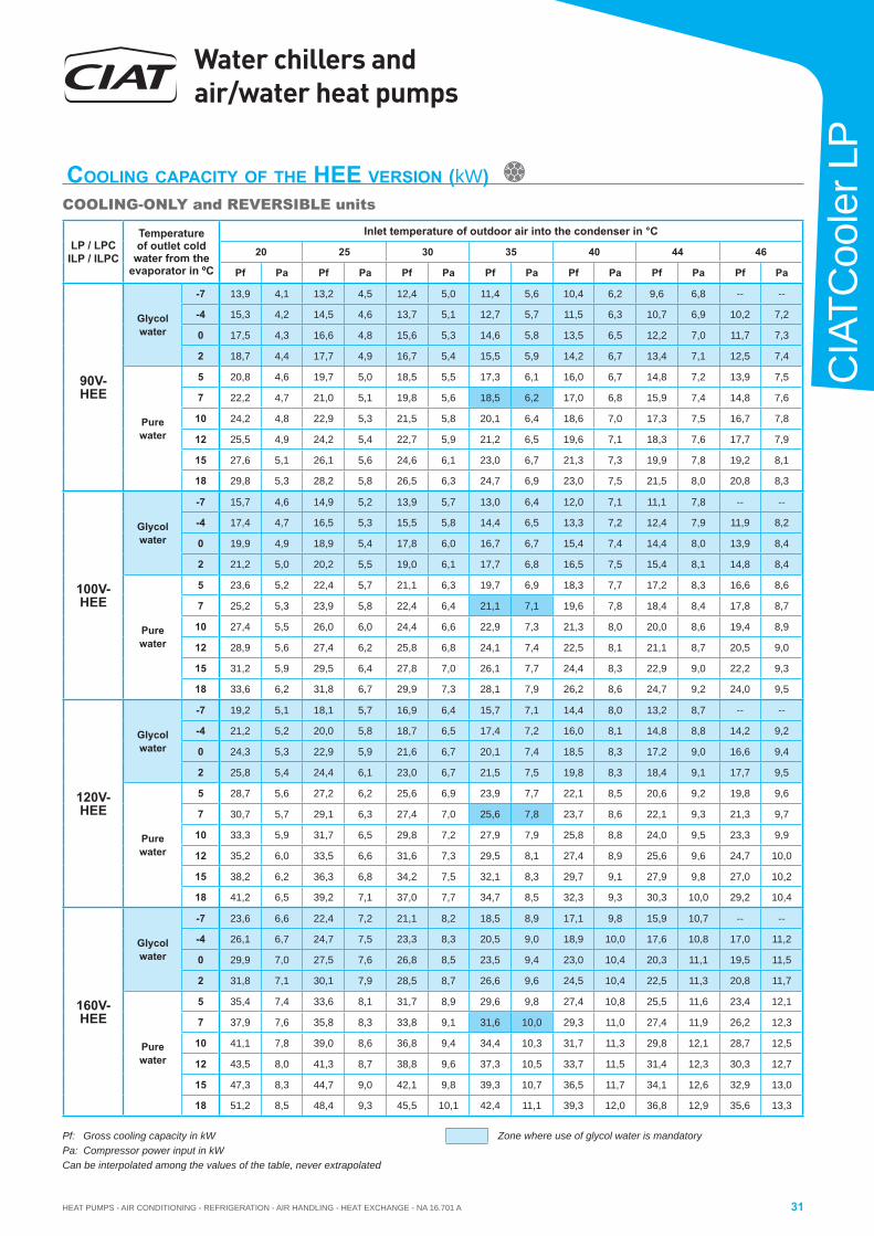
HEAT PUMPS - AIR CONDITIONING - REFRIGERATION - AIR HANDLING - HEAT EXCHANGE - NA 16.701 A
Water chillers and air/water heat pumps
31
CIA
TCoo
ler L
P
LP / LPCILP / ILPC
Temperature of outlet cold
water from the evaporator in ºC
Inlet temperature of outdoor air into the condenser in °C
20 25 30 35 40 44 46
Pf Pa Pf Pa Pf Pa Pf Pa Pf Pa Pf Pa Pf Pa
90V-HEE
Glycol water
-7 13,9 4,1 13,2 4,5 12,4 5,0 11,4 5,6 10,4 6,2 9,6 6,8 -- --
-4 15,3 4,2 14,5 4,6 13,7 5,1 12,7 5,7 11,5 6,3 10,7 6,9 10,2 7,2
0 17,5 4,3 16,6 4,8 15,6 5,3 14,6 5,8 13,5 6,5 12,2 7,0 11,7 7,3
2 18,7 4,4 17,7 4,9 16,7 5,4 15,5 5,9 14,2 6,7 13,4 7,1 12,5 7,4
Pure water
5 20,8 4,6 19,7 5,0 18,5 5,5 17,3 6,1 16,0 6,7 14,8 7,2 13,9 7,5
7 22,2 4,7 21,0 5,1 19,8 5,6 18,5 6,2 17,0 6,8 15,9 7,4 14,8 7,6
10 24,2 4,8 22,9 5,3 21,5 5,8 20,1 6,4 18,6 7,0 17,3 7,5 16,7 7,8
12 25,5 4,9 24,2 5,4 22,7 5,9 21,2 6,5 19,6 7,1 18,3 7,6 17,7 7,9
15 27,6 5,1 26,1 5,6 24,6 6,1 23,0 6,7 21,3 7,3 19,9 7,8 19,2 8,1
18 29,8 5,3 28,2 5,8 26,5 6,3 24,7 6,9 23,0 7,5 21,5 8,0 20,8 8,3
100V-HEE
Glycol water
-7 15,7 4,6 14,9 5,2 13,9 5,7 13,0 6,4 12,0 7,1 11,1 7,8 -- --
-4 17,4 4,7 16,5 5,3 15,5 5,8 14,4 6,5 13,3 7,2 12,4 7,9 11,9 8,2
0 19,9 4,9 18,9 5,4 17,8 6,0 16,7 6,7 15,4 7,4 14,4 8,0 13,9 8,4
2 21,2 5,0 20,2 5,5 19,0 6,1 17,7 6,8 16,5 7,5 15,4 8,1 14,8 8,4
Pure water
5 23,6 5,2 22,4 5,7 21,1 6,3 19,7 6,9 18,3 7,7 17,2 8,3 16,6 8,6
7 25,2 5,3 23,9 5,8 22,4 6,4 21,1 7,1 19,6 7,8 18,4 8,4 17,8 8,7
10 27,4 5,5 26,0 6,0 24,4 6,6 22,9 7,3 21,3 8,0 20,0 8,6 19,4 8,9
12 28,9 5,6 27,4 6,2 25,8 6,8 24,1 7,4 22,5 8,1 21,1 8,7 20,5 9,0
15 31,2 5,9 29,5 6,4 27,8 7,0 26,1 7,7 24,4 8,3 22,9 9,0 22,2 9,3
18 33,6 6,2 31,8 6,7 29,9 7,3 28,1 7,9 26,2 8,6 24,7 9,2 24,0 9,5
120V-HEE
Glycol water
-7 19,2 5,1 18,1 5,7 16,9 6,4 15,7 7,1 14,4 8,0 13,2 8,7 -- --
-4 21,2 5,2 20,0 5,8 18,7 6,5 17,4 7,2 16,0 8,1 14,8 8,8 14,2 9,2
0 24,3 5,3 22,9 5,9 21,6 6,7 20,1 7,4 18,5 8,3 17,2 9,0 16,6 9,4
2 25,8 5,4 24,4 6,1 23,0 6,7 21,5 7,5 19,8 8,3 18,4 9,1 17,7 9,5
Pure water
5 28,7 5,6 27,2 6,2 25,6 6,9 23,9 7,7 22,1 8,5 20,6 9,2 19,8 9,6
7 30,7 5,7 29,1 6,3 27,4 7,0 25,6 7,8 23,7 8,6 22,1 9,3 21,3 9,7
10 33,3 5,9 31,7 6,5 29,8 7,2 27,9 7,9 25,8 8,8 24,0 9,5 23,3 9,9
12 35,2 6,0 33,5 6,6 31,6 7,3 29,5 8,1 27,4 8,9 25,6 9,6 24,7 10,0
15 38,2 6,2 36,3 6,8 34,2 7,5 32,1 8,3 29,7 9,1 27,9 9,8 27,0 10,2
18 41,2 6,5 39,2 7,1 37,0 7,7 34,7 8,5 32,3 9,3 30,3 10,0 29,2 10,4
160V-HEE
Glycol water
-7 23,6 6,6 22,4 7,2 21,1 8,2 18,5 8,9 17,1 9,8 15,9 10,7 -- --
-4 26,1 6,7 24,7 7,5 23,3 8,3 20,5 9,0 18,9 10,0 17,6 10,8 17,0 11,2
0 29,9 7,0 27,5 7,6 26,8 8,5 23,5 9,4 23,0 10,4 20,3 11,1 19,5 11,5
2 31,8 7,1 30,1 7,9 28,5 8,7 26,6 9,6 24,5 10,4 22,5 11,3 20,8 11,7
Pure water
5 35,4 7,4 33,6 8,1 31,7 8,9 29,6 9,8 27,4 10,8 25,5 11,6 23,4 12,1
7 37,9 7,6 35,8 8,3 33,8 9,1 31,6 10,0 29,3 11,0 27,4 11,9 26,2 12,3
10 41,1 7,8 39,0 8,6 36,8 9,4 34,4 10,3 31,7 11,3 29,8 12,1 28,7 12,5
12 43,5 8,0 41,3 8,7 38,8 9,6 37,3 10,5 33,7 11,5 31,4 12,3 30,3 12,7
15 47,3 8,3 44,7 9,0 42,1 9,8 39,3 10,7 36,5 11,7 34,1 12,6 32,9 13,0
18 51,2 8,5 48,4 9,3 45,5 10,1 42,4 11,1 39,3 12,0 36,8 12,9 35,6 13,3
Pf: Gross cooling capacity in kWPa: Compressor power input in kWCan be interpolated among the values of the table, never extrapolated
COOLING CAPACITY OF THE HEE VERSION (kW)COOLING-ONLY and REVERSIBLE units
Zone where use of glycol water is mandatory
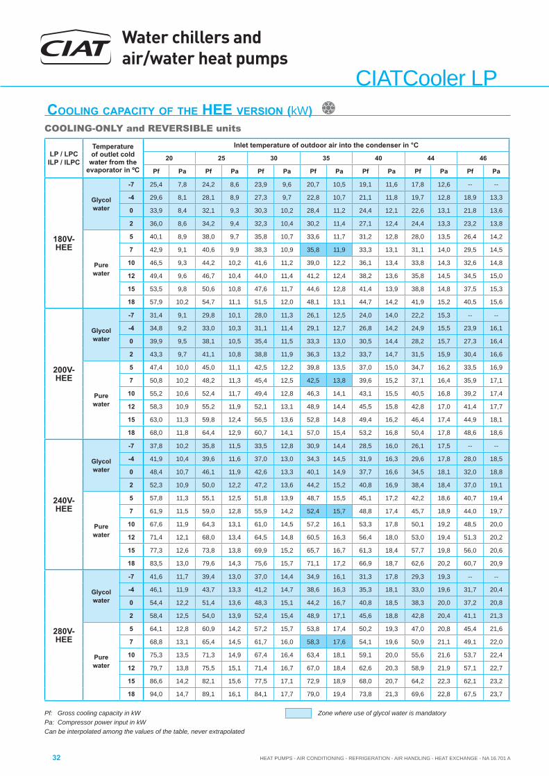
Water chillers and air/water heat pumps
HEAT PUMPS - AIR CONDITIONING - REFRIGERATION - AIR HANDLING - HEAT EXCHANGE - NA 16.701 A32
CIATCooler LP
Pf: Gross cooling capacity in kWPa: Compressor power input in kWCan be interpolated among the values of the table, never extrapolated
COOLING CAPACITY OF THE HEE VERSION (kW)COOLING-ONLY and REVERSIBLE units
Zone where use of glycol water is mandatory
LP / LPCILP / ILPC
Temperature of outlet cold
water from the evaporator in ºC
Inlet temperature of outdoor air into the condenser in °C
20 25 30 35 40 44 46
Pf Pa Pf Pa Pf Pa Pf Pa Pf Pa Pf Pa Pf Pa
180V-HEE
Glycol water
-7 25,4 7,8 24,2 8,6 23,9 9,6 20,7 10,5 19,1 11,6 17,8 12,6 -- --
-4 29,6 8,1 28,1 8,9 27,3 9,7 22,8 10,7 21,1 11,8 19,7 12,8 18,9 13,3
0 33,9 8,4 32,1 9,3 30,3 10,2 28,4 11,2 24,4 12,1 22,6 13,1 21,8 13,6
2 36,0 8,6 34,2 9,4 32,3 10,4 30,2 11,4 27,1 12,4 24,4 13,3 23,2 13,8
Pure water
5 40,1 8,9 38,0 9,7 35,8 10,7 33,6 11,7 31,2 12,8 28,0 13,5 26,4 14,2
7 42,9 9,1 40,6 9,9 38,3 10,9 35,8 11,9 33,3 13,1 31,1 14,0 29,5 14,5
10 46,5 9,3 44,2 10,2 41,6 11,2 39,0 12,2 36,1 13,4 33,8 14,3 32,6 14,8
12 49,4 9,6 46,7 10,4 44,0 11,4 41,2 12,4 38,2 13,6 35,8 14,5 34,5 15,0
15 53,5 9,8 50,6 10,8 47,6 11,7 44,6 12,8 41,4 13,9 38,8 14,8 37,5 15,3
18 57,9 10,2 54,7 11,1 51,5 12,0 48,1 13,1 44,7 14,2 41,9 15,2 40,5 15,6
200V-HEE
Glycol water
-7 31,4 9,1 29,8 10,1 28,0 11,3 26,1 12,5 24,0 14,0 22,2 15,3 -- --
-4 34,8 9,2 33,0 10,3 31,1 11,4 29,1 12,7 26,8 14,2 24,9 15,5 23,9 16,1
0 39,9 9,5 38,1 10,5 35,4 11,5 33,3 13,0 30,5 14,4 28,2 15,7 27,3 16,4
2 43,3 9,7 41,1 10,8 38,8 11,9 36,3 13,2 33,7 14,7 31,5 15,9 30,4 16,6
Pure water
5 47,4 10,0 45,0 11,1 42,5 12,2 39,8 13,5 37,0 15,0 34,7 16,2 33,5 16,9
7 50,8 10,2 48,2 11,3 45,4 12,5 42,5 13,8 39,6 15,2 37,1 16,4 35,9 17,1
10 55,2 10,6 52,4 11,7 49,4 12,8 46,3 14,1 43,1 15,5 40,5 16,8 39,2 17,4
12 58,3 10,9 55,2 11,9 52,1 13,1 48,9 14,4 45,5 15,8 42,8 17,0 41,4 17,7
15 63,0 11,3 59,8 12,4 56,5 13,6 52,8 14,8 49,4 16,2 46,4 17,4 44,9 18,1
18 68,0 11,8 64,4 12,9 60,7 14,1 57,0 15,4 53,2 16,8 50,4 17,8 48,6 18,6
240V-HEE
Glycol water
-7 37,8 10,2 35,8 11,5 33,5 12,8 30,9 14,4 28,5 16,0 26,1 17,5 -- --
-4 41,9 10,4 39,6 11,6 37,0 13,0 34,3 14,5 31,9 16,3 29,6 17,8 28,0 18,5
0 48,4 10,7 46,1 11,9 42,6 13,3 40,1 14,9 37,7 16,6 34,5 18,1 32,0 18,8
2 52,3 10,9 50,0 12,2 47,2 13,6 44,2 15,2 40,8 16,9 38,4 18,4 37,0 19,1
Pure water
5 57,8 11,3 55,1 12,5 51,8 13,9 48,7 15,5 45,1 17,2 42,2 18,6 40,7 19,4
7 61,9 11,5 59,0 12,8 55,9 14,2 52,4 15,7 48,8 17,4 45,7 18,9 44,0 19,7
10 67,6 11,9 64,3 13,1 61,0 14,5 57,2 16,1 53,3 17,8 50,1 19,2 48,5 20,0
12 71,4 12,1 68,0 13,4 64,5 14,8 60,5 16,3 56,4 18,0 53,0 19,4 51,3 20,2
15 77,3 12,6 73,8 13,8 69,9 15,2 65,7 16,7 61,3 18,4 57,7 19,8 56,0 20,6
18 83,5 13,0 79,6 14,3 75,6 15,7 71,1 17,2 66,9 18,7 62,6 20,2 60,7 20,9
280V-HEE
Glycol water
-7 41,6 11,7 39,4 13,0 37,0 14,4 34,9 16,1 31,3 17,8 29,3 19,3 -- --
-4 46,1 11,9 43,7 13,3 41,2 14,7 38,6 16,3 35,3 18,1 33,0 19,6 31,7 20,4
0 54,4 12,2 51,4 13,6 48,3 15,1 44,2 16,7 40,8 18,5 38,3 20,0 37,2 20,8
2 58,4 12,5 54,0 13,9 52,4 15,4 48,9 17,1 45,6 18,8 42,8 20,4 41,1 21,3
Pure water
5 64,1 12,8 60,9 14,2 57,2 15,7 53,8 17,4 50,2 19,3 47,0 20,8 45,4 21,6
7 68,8 13,1 65,4 14,5 61,7 16,0 58,3 17,6 54,1 19,6 50,9 21,1 49,1 22,0
10 75,3 13,5 71,3 14,9 67,4 16,4 63,4 18,1 59,1 20,0 55,6 21,6 53,7 22,4
12 79,7 13,8 75,5 15,1 71,4 16,7 67,0 18,4 62,6 20,3 58,9 21,9 57,1 22,7
15 86,6 14,2 82,1 15,6 77,5 17,1 72,9 18,9 68,0 20,7 64,2 22,3 62,1 23,2
18 94,0 14,7 89,1 16,1 84,1 17,7 79,0 19,4 73,8 21,3 69,6 22,8 67,5 23,7
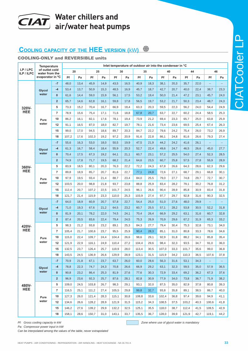
HEAT PUMPS - AIR CONDITIONING - REFRIGERATION - AIR HANDLING - HEAT EXCHANGE - NA 16.701 A
Water chillers and air/water heat pumps
33
CIA
TCoo
ler L
P
LP / LPCILP / ILPC
Temperature of outlet cold
water from the evaporator in ºC
Inlet temperature of outdoor air into the condenser in °C
20 25 30 35 40 44 46
Pf Pa Pf Pa Pf Pa Pf Pa Pf Pa Pf Pa Pf Pa
320V-HEE
Glycol water
-7 48,0 13,4 45,9 14,9 43,5 16,5 40,9 18,3 38,1 20,3 35,7 22,0 -- --
-4 53,4 13,7 50,9 15,3 48,5 16,9 45,7 18,7 42,7 20,7 40,0 22,4 38,7 23,3
0 61,6 14,4 59,0 15,9 56,1 17,5 53,2 19,4 50,0 21,4 47,2 23,1 45,7 24,0
2 65,7 14,6 62,8 16,1 59,8 17,8 56,5 19,7 53,2 21,7 50,3 23,4 48,7 24,3
Pure water
5 73,3 15,2 70,4 16,7 66,9 18,4 63,3 20,3 59,5 22,3 56,2 24,0 54,4 24,9
7 78,9 15,6 75,4 17,1 71,6 18,8 67,8 20,7 63,7 22,7 60,2 24,4 58,5 25,3
10 86,2 16,1 82,1 17,6 78,1 19,4 73,9 21,2 69,4 23,3 65,7 25,0 63,8 25,9
12 91,1 16,5 87,0 18,0 82,7 19,7 78,1 21,6 73,4 23,6 69,5 25,4 67,4 26,3
15 99,0 17,0 94,5 18,6 89,7 20,3 84,7 22,2 79,6 24,2 75,4 26,0 73,2 26,9
18 107,2 17,6 102,3 19,2 97,2 20,9 91,6 22,8 86,1 24,8 81,6 26,6 79,3 27,4
360V-HEE
Glycol water
-7 55,6 16,3 53,0 18,0 50,5 19,9 47,5 21,9 44,2 24,2 41,6 26,1 -- --
-4 61,3 16,7 58,4 18,4 55,9 20,3 52,7 22,4 49,6 24,7 46,5 26,6 45,0 27,7
0 70,4 17,5 67,3 19,2 64,1 21,1 60,7 23,1 57,2 25,5 54,0 27,4 52,3 28,5
2 74,9 17,8 71,7 19,5 68,2 21,4 64,6 23,5 60,7 25,8 57,5 27,8 55,9 28,9
Pure water
5 83,9 18,5 80,1 20,3 76,3 22,2 72,2 24,3 67,8 26,6 64,3 28,6 62,3 29,6
7 89,8 18,9 85,7 20,7 81,6 22,7 77,1 24,8 72,6 27,1 68,7 29,1 66,8 30,1
10 97,9 19,5 93,4 21,4 88,7 23,4 84,0 25,5 79,0 27,7 74,8 29,7 72,7 30,7
12 103,5 20,0 98,8 21,8 93,7 23,8 88,8 25,9 83,4 28,2 79,1 30,2 76,8 31,2
15 112,4 20,7 107,2 22,5 101,7 24,5 96,1 26,6 90,4 28,9 85,8 30,9 83,4 31,8
18 121,7 21,4 115,9 23,3 110,0 25,3 103,9 27,4 97,7 29,7 92,8 31,6 90,3 32,5
420V-HEE
Glycol water
-7 64,0 18,9 60,9 20,7 57,8 22,7 54,4 25,0 51,0 27,6 48,0 29,9 -- --
-4 71,0 19,3 67,6 21,2 64,5 23,2 60,7 25,5 57,1 28,2 53,8 30,5 52,2 31,8
0 81,9 20,1 78,2 22,0 74,5 24,1 70,4 26,4 66,9 29,2 63,1 31,6 60,7 32,8
2 87,4 20,5 83,6 22,4 79,4 24,5 75,3 26,9 70,9 29,6 67,2 31,9 65,3 33,2
Pure water
5 98,3 21,2 93,8 23,2 89,1 25,3 84,3 27,7 79,4 30,4 75,3 32,8 73,1 34,0
7 105,4 21,7 100,6 23,7 95,5 25,9 90,4 28,3 85,1 31,0 80,8 33,3 78,6 34,6
10 115,0 22,4 109,7 24,4 104,4 26,6 98,6 29,1 92,9 31,8 88,2 34,1 85,8 35,4
12 121,9 22,9 116,1 24,9 110,4 27,2 104,4 29,6 98,4 32,3 93,5 34,7 91,0 36,0
15 132,5 23,7 126,4 25,7 119,9 28,0 113,4 30,5 107,0 33,3 101,7 35,6 99,0 36,8
18 143,5 24,5 136,9 26,6 129,9 28,9 123,1 31,5 115,9 34,2 110,3 36,5 107,6 37,8
480V-HEE
Glycol water
-7 70,9 21,8 67,1 23,7 63,7 26,0 60,0 28,6 56,3 31,6 53,1 34,3 -- --
-4 78,8 22,3 74,7 24,3 70,8 26,6 66,9 29,2 63,1 32,3 59,5 35,0 57,9 36,5
0 90,8 23,2 86,4 25,3 81,9 27,6 77,6 30,3 72,9 33,4 69,2 36,2 67,3 37,6
2 96,9 23,6 92,3 25,7 87,6 28,1 82,8 30,9 77,9 34,0 73,8 36,7 71,9 38,2
Pure water
5 109,0 24,5 103,8 26,7 98,3 29,1 93,1 32,0 87,5 35,0 82,9 37,8 80,8 39,3
7 116,5 25,1 111,2 27,4 105,5 29,8 99,8 32,7 93,8 35,8 89,1 38,5 86,7 40,0
10 127,3 26,0 121,4 28,3 115,1 30,8 108,8 33,6 102,4 36,8 97,4 39,6 94,9 41,1
12 134,6 26,6 128,2 28,9 121,9 31,5 115,2 34,3 108,5 37,5 103,2 40,3 100,6 41,8
15 146,2 27,6 139,2 29,9 132,2 32,5 125,1 35,5 118,0 38,7 112,4 41,5 109,5 42,9
18 158,1 28,6 150,7 31,0 143,1 33,7 135,5 36,7 128,0 39,9 121,9 42,7 119,1 44,2
Pf: Gross cooling capacity in kWPa: Compressor power input in kWCan be interpolated among the values of the table, never extrapolated
COOLING CAPACITY OF THE HEE VERSION (kW)COOLING-ONLY and REVERSIBLE units
Zone where use of glycol water is mandatory
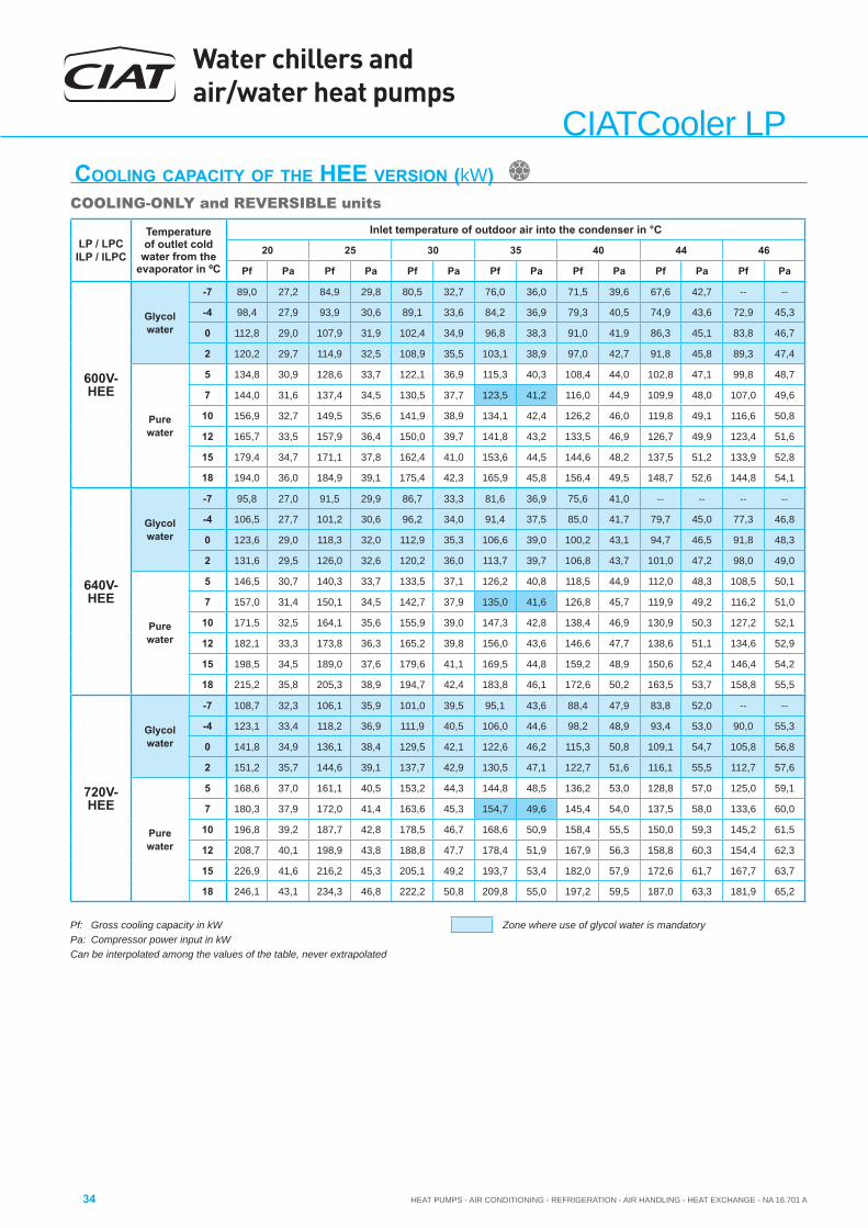
Water chillers and air/water heat pumps
HEAT PUMPS - AIR CONDITIONING - REFRIGERATION - AIR HANDLING - HEAT EXCHANGE - NA 16.701 A34
CIATCooler LP
Pf: Gross cooling capacity in kWPa: Compressor power input in kWCan be interpolated among the values of the table, never extrapolated
COOLING CAPACITY OF THE HEE VERSION (kW)COOLING-ONLY and REVERSIBLE units
Zone where use of glycol water is mandatory
LP / LPCILP / ILPC
Temperature of outlet cold
water from the evaporator in ºC
Inlet temperature of outdoor air into the condenser in °C
20 25 30 35 40 44 46
Pf Pa Pf Pa Pf Pa Pf Pa Pf Pa Pf Pa Pf Pa
600V-HEE
Glycol water
-7 89,0 27,2 84,9 29,8 80,5 32,7 76,0 36,0 71,5 39,6 67,6 42,7 -- --
-4 98,4 27,9 93,9 30,6 89,1 33,6 84,2 36,9 79,3 40,5 74,9 43,6 72,9 45,3
0 112,8 29,0 107,9 31,9 102,4 34,9 96,8 38,3 91,0 41,9 86,3 45,1 83,8 46,7
2 120,2 29,7 114,9 32,5 108,9 35,5 103,1 38,9 97,0 42,7 91,8 45,8 89,3 47,4
Pure water
5 134,8 30,9 128,6 33,7 122,1 36,9 115,3 40,3 108,4 44,0 102,8 47,1 99,8 48,7
7 144,0 31,6 137,4 34,5 130,5 37,7 123,5 41,2 116,0 44,9 109,9 48,0 107,0 49,6
10 156,9 32,7 149,5 35,6 141,9 38,9 134,1 42,4 126,2 46,0 119,8 49,1 116,6 50,8
12 165,7 33,5 157,9 36,4 150,0 39,7 141,8 43,2 133,5 46,9 126,7 49,9 123,4 51,6
15 179,4 34,7 171,1 37,8 162,4 41,0 153,6 44,5 144,6 48,2 137,5 51,2 133,9 52,8
18 194,0 36,0 184,9 39,1 175,4 42,3 165,9 45,8 156,4 49,5 148,7 52,6 144,8 54,1
640V-HEE
Glycol water
-7 95,8 27,0 91,5 29,9 86,7 33,3 81,6 36,9 75,6 41,0 -- -- -- --
-4 106,5 27,7 101,2 30,6 96,2 34,0 91,4 37,5 85,0 41,7 79,7 45,0 77,3 46,8
0 123,6 29,0 118,3 32,0 112,9 35,3 106,6 39,0 100,2 43,1 94,7 46,5 91,8 48,3
2 131,6 29,5 126,0 32,6 120,2 36,0 113,7 39,7 106,8 43,7 101,0 47,2 98,0 49,0
Pure water
5 146,5 30,7 140,3 33,7 133,5 37,1 126,2 40,8 118,5 44,9 112,0 48,3 108,5 50,1
7 157,0 31,4 150,1 34,5 142,7 37,9 135,0 41,6 126,8 45,7 119,9 49,2 116,2 51,0
10 171,5 32,5 164,1 35,6 155,9 39,0 147,3 42,8 138,4 46,9 130,9 50,3 127,2 52,1
12 182,1 33,3 173,8 36,3 165,2 39,8 156,0 43,6 146,6 47,7 138,6 51,1 134,6 52,9
15 198,5 34,5 189,0 37,6 179,6 41,1 169,5 44,8 159,2 48,9 150,6 52,4 146,4 54,2
18 215,2 35,8 205,3 38,9 194,7 42,4 183,8 46,1 172,6 50,2 163,5 53,7 158,8 55,5
720V-HEE
Glycol water
-7 108,7 32,3 106,1 35,9 101,0 39,5 95,1 43,6 88,4 47,9 83,8 52,0 -- --
-4 123,1 33,4 118,2 36,9 111,9 40,5 106,0 44,6 98,2 48,9 93,4 53,0 90,0 55,3
0 141,8 34,9 136,1 38,4 129,5 42,1 122,6 46,2 115,3 50,8 109,1 54,7 105,8 56,8
2 151,2 35,7 144,6 39,1 137,7 42,9 130,5 47,1 122,7 51,6 116,1 55,5 112,7 57,6
Pure water
5 168,6 37,0 161,1 40,5 153,2 44,3 144,8 48,5 136,2 53,0 128,8 57,0 125,0 59,1
7 180,3 37,9 172,0 41,4 163,6 45,3 154,7 49,6 145,4 54,0 137,5 58,0 133,6 60,0
10 196,8 39,2 187,7 42,8 178,5 46,7 168,6 50,9 158,4 55,5 150,0 59,3 145,2 61,5
12 208,7 40,1 198,9 43,8 188,8 47,7 178,4 51,9 167,9 56,3 158,8 60,3 154,4 62,3
15 226,9 41,6 216,2 45,3 205,1 49,2 193,7 53,4 182,0 57,9 172,6 61,7 167,7 63,7
18 246,1 43,1 234,3 46,8 222,2 50,8 209,8 55,0 197,2 59,5 187,0 63,3 181,9 65,2

HEAT PUMPS - AIR CONDITIONING - REFRIGERATION - AIR HANDLING - HEAT EXCHANGE - NA 16.701 A
Water chillers and air/water heat pumps
35
CIA
TCoo
ler L
P
Pc: Gross heating capacity in kWPa: Compressor power input in kWCan be interpolated among the values of the table, never extrapolated Variation of the relative humidity for the calculations: -20ºC 95%RH / +7ºC 85%RH / +27ºC 50%RH
HEATING CAPACITY OF THE HEE VERSION (kW)REVERSIBLE units
ILP / ILPCInlet temperature of outdoor air into the
evaporator in ºC DB
Temperature of outlet hot water from the condenser in ºC30 35 40 45 50 55
Pc Pa Pc Pa Pc Pa Pc Pa Pc Pa Pc Pa
90V-HEE
-15 12,5 4,2 -- -- -- -- -- -- -- -- -- ---12 13,5 4,3 13,4 4,7 0,0 -- -- -- -- -- -- ---10 14,3 4,3 14,1 4,7 14,0 5,3 -- -- -- -- -- ---5 16,6 4,3 16,4 4,8 15,9 5,4 15,7 6,0 -- -- -- --0 19,0 4,3 18,7 4,8 18,4 5,4 18,0 6,0 -- -- -- --5 21,5 4,4 21,1 4,8 20,7 5,4 20,3 6,0 19,8 6,8 -- --7 22,6 4,4 22,1 4,9 21,7 5,4 21,3 6,0 20,8 6,8 20,0 7,710 24,1 4,4 23,6 4,9 23,1 5,4 22,6 6,1 22,1 6,8 21,1 7,715 26,4 4,5 25,7 5,0 25,2 5,5 24,6 6,1 23,9 6,8 23,3 7,720 28,0 4,5 27,4 5,0 26,8 5,5 26,2 6,1 25,6 6,8 25,1 7,7
100V-HEE
-15 13,7 4,8 13,4 5,4 -- -- -- -- -- -- -- ---12 15,2 4,9 14,7 5,5 14,5 6,2 -- -- -- -- -- ---10 16,1 4,9 15,6 5,5 15,4 6,2 -- -- -- -- -- ---5 18,4 4,9 18,2 5,5 17,5 6,2 17,3 6,9 -- -- -- --0 21,1 4,9 20,8 5,5 20,5 6,2 19,7 6,9 19,3 7,8 -- --5 23,9 5,0 23,5 5,5 23,1 6,2 22,6 6,9 22,1 7,8 21,3 8,87 25,1 5,0 24,6 5,5 24,2 6,2 23,8 7,0 23,2 7,8 22,2 8,810 26,7 5,0 26,2 5,5 25,7 6,2 25,2 7,0 24,7 7,8 23,5 8,815 29,2 5,0 28,7 5,6 28,0 6,2 27,4 7,0 26,8 7,8 26,1 8,920 31,1 5,0 30,4 5,6 29,8 6,3 29,2 7,0 28,5 7,8 27,9 8,9
120V-HEE
-15 17,1 5,5 16,8 6,2 16,5 7,0 -- -- -- -- -- ---12 18,7 5,6 18,3 6,3 18,0 7,1 -- -- -- -- -- ---10 19,8 5,6 19,4 6,3 19,0 7,2 -- -- -- -- -- ---5 22,8 5,7 22,3 6,4 21,8 7,2 21,4 8,1 -- -- -- --0 26,1 5,7 25,6 6,4 25,0 7,2 24,5 8,1 23,8 9,2 -- --5 29,7 5,7 29,0 6,4 28,4 7,3 27,7 8,1 27,0 9,2 26,2 10,37 31,1 5,7 30,4 6,5 29,7 7,3 29,1 8,2 28,3 9,2 27,4 10,4
10 33,2 5,7 32,5 6,5 31,7 7,3 30,9 8,2 30,0 9,2 29,1 10,415 36,2 5,8 35,4 6,5 34,6 7,3 33,7 8,2 32,7 9,2 31,7 10,420 38,6 5,8 37,9 6,5 37,0 7,3 36,2 8,2 35,4 9,2 34,5 10,4
160V-HEE
-15 20,4 7,0 20,1 7,9 -- -- -- -- -- -- -- ---12 23,1 7,1 21,9 7,9 21,6 8,9 -- -- -- -- -- ---10 24,5 7,2 23,3 8,0 22,9 8,9 -- -- -- -- -- ---5 28,2 7,2 26,8 8,2 26,2 9,1 25,7 10,2 -- -- -- --0 32,3 7,4 31,8 8,2 31,3 9,2 30,7 10,3 30,0 11,5 -- --5 36,7 7,5 36,0 8,4 35,3 9,3 34,5 10,4 33,7 11,6 31,3 12,87 38,4 7,6 37,7 8,4 36,9 9,4 36,2 10,4 35,2 11,6 32,7 12,910 41,0 7,7 40,2 8,5 39,3 9,4 38,3 10,5 37,3 11,6 35,4 13,015 44,8 7,8 43,9 8,6 42,8 9,5 41,7 10,6 40,5 11,8 39,2 13,120 47,9 7,8 46,8 8,7 45,7 9,6 44,8 10,7 43,8 11,9 42,6 13,2
180V-HEE
-15 24,8 8,4 23,3 9,3 -- -- -- -- -- -- -- ---12 27,1 8,5 25,4 9,4 23,9 10,5 -- -- -- -- -- ---10 28,7 8,5 27,7 9,5 26,5 10,6 -- -- -- -- -- ---5 33,0 8,6 32,6 9,6 30,9 10,6 29,9 11,9 -- -- -- --0 37,7 8,8 37,2 9,8 36,6 10,8 34,9 12,0 33,2 13,4 -- --5 42,8 9,0 42,0 9,9 41,2 11,0 40,5 12,1 38,9 13,5 37,2 15,17 44,8 9,1 44,0 10,0 43,0 11,0 42,3 12,2 41,2 13,6 38,9 15,110 47,9 9,1 46,8 10,1 45,9 11,1 44,8 12,3 43,6 13,7 42,3 15,215 52,3 9,2 51,1 10,2 50,0 11,2 48,7 12,3 47,3 13,7 45,8 15,320 55,6 9,3 54,5 10,3 53,3 11,3 52,2 12,5 51,0 13,8 49,8 15,3
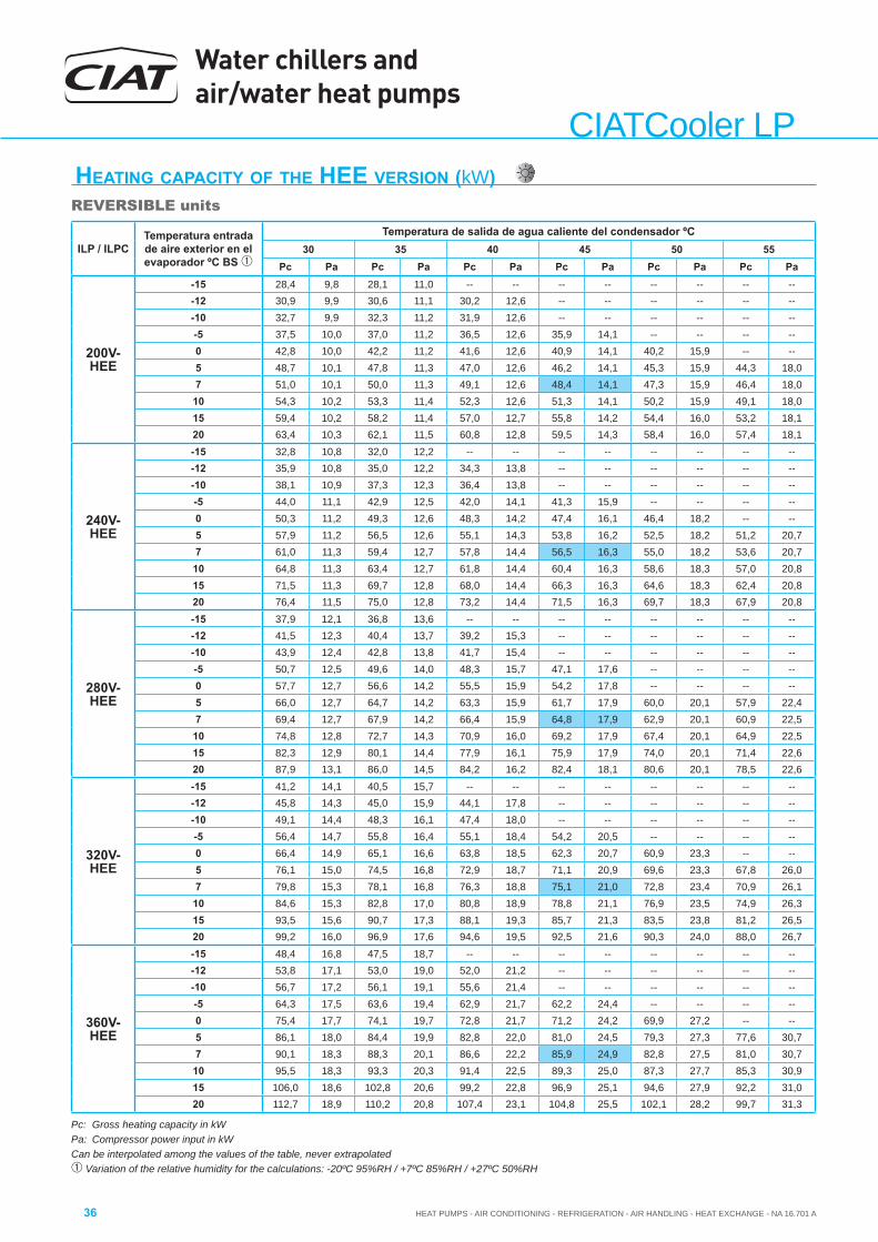
Water chillers and air/water heat pumps
HEAT PUMPS - AIR CONDITIONING - REFRIGERATION - AIR HANDLING - HEAT EXCHANGE - NA 16.701 A36
CIATCooler LP
Pc: Gross heating capacity in kWPa: Compressor power input in kWCan be interpolated among the values of the table, never extrapolated Variation of the relative humidity for the calculations: -20ºC 95%RH / +7ºC 85%RH / +27ºC 50%RH
HEATING CAPACITY OF THE HEE VERSION (kW)REVERSIBLE units
ILP / ILPCTemperatura entrada de aire exterior en el evaporador ºC BS
Temperatura de salida de agua caliente del condensador ºC30 35 40 45 50 55
Pc Pa Pc Pa Pc Pa Pc Pa Pc Pa Pc Pa
200V-HEE
-15 28,4 9,8 28,1 11,0 -- -- -- -- -- -- -- ---12 30,9 9,9 30,6 11,1 30,2 12,6 -- -- -- -- -- ---10 32,7 9,9 32,3 11,2 31,9 12,6 -- -- -- -- -- ---5 37,5 10,0 37,0 11,2 36,5 12,6 35,9 14,1 -- -- -- --0 42,8 10,0 42,2 11,2 41,6 12,6 40,9 14,1 40,2 15,9 -- --5 48,7 10,1 47,8 11,3 47,0 12,6 46,2 14,1 45,3 15,9 44,3 18,07 51,0 10,1 50,0 11,3 49,1 12,6 48,4 14,1 47,3 15,9 46,4 18,010 54,3 10,2 53,3 11,4 52,3 12,6 51,3 14,1 50,2 15,9 49,1 18,015 59,4 10,2 58,2 11,4 57,0 12,7 55,8 14,2 54,4 16,0 53,2 18,120 63,4 10,3 62,1 11,5 60,8 12,8 59,5 14,3 58,4 16,0 57,4 18,1
240V-HEE
-15 32,8 10,8 32,0 12,2 -- -- -- -- -- -- -- ---12 35,9 10,8 35,0 12,2 34,3 13,8 -- -- -- -- -- ---10 38,1 10,9 37,3 12,3 36,4 13,8 -- -- -- -- -- ---5 44,0 11,1 42,9 12,5 42,0 14,1 41,3 15,9 -- -- -- --0 50,3 11,2 49,3 12,6 48,3 14,2 47,4 16,1 46,4 18,2 -- --5 57,9 11,2 56,5 12,6 55,1 14,3 53,8 16,2 52,5 18,2 51,2 20,77 61,0 11,3 59,4 12,7 57,8 14,4 56,5 16,3 55,0 18,2 53,6 20,710 64,8 11,3 63,4 12,7 61,8 14,4 60,4 16,3 58,6 18,3 57,0 20,815 71,5 11,3 69,7 12,8 68,0 14,4 66,3 16,3 64,6 18,3 62,4 20,820 76,4 11,5 75,0 12,8 73,2 14,4 71,5 16,3 69,7 18,3 67,9 20,8
280V-HEE
-15 37,9 12,1 36,8 13,6 -- -- -- -- -- -- -- ---12 41,5 12,3 40,4 13,7 39,2 15,3 -- -- -- -- -- ---10 43,9 12,4 42,8 13,8 41,7 15,4 -- -- -- -- -- ---5 50,7 12,5 49,6 14,0 48,3 15,7 47,1 17,6 -- -- -- --0 57,7 12,7 56,6 14,2 55,5 15,9 54,2 17,8 -- -- -- --5 66,0 12,7 64,7 14,2 63,3 15,9 61,7 17,9 60,0 20,1 57,9 22,47 69,4 12,7 67,9 14,2 66,4 15,9 64,8 17,9 62,9 20,1 60,9 22,510 74,8 12,8 72,7 14,3 70,9 16,0 69,2 17,9 67,4 20,1 64,9 22,515 82,3 12,9 80,1 14,4 77,9 16,1 75,9 17,9 74,0 20,1 71,4 22,620 87,9 13,1 86,0 14,5 84,2 16,2 82,4 18,1 80,6 20,1 78,5 22,6
320V-HEE
-15 41,2 14,1 40,5 15,7 -- -- -- -- -- -- -- ---12 45,8 14,3 45,0 15,9 44,1 17,8 -- -- -- -- -- ---10 49,1 14,4 48,3 16,1 47,4 18,0 -- -- -- -- -- ---5 56,4 14,7 55,8 16,4 55,1 18,4 54,2 20,5 -- -- -- --0 66,4 14,9 65,1 16,6 63,8 18,5 62,3 20,7 60,9 23,3 -- --5 76,1 15,0 74,5 16,8 72,9 18,7 71,1 20,9 69,6 23,3 67,8 26,07 79,8 15,3 78,1 16,8 76,3 18,8 75,1 21,0 72,8 23,4 70,9 26,110 84,6 15,3 82,8 17,0 80,8 18,9 78,8 21,1 76,9 23,5 74,9 26,315 93,5 15,6 90,7 17,3 88,1 19,3 85,7 21,3 83,5 23,8 81,2 26,520 99,2 16,0 96,9 17,6 94,6 19,5 92,5 21,6 90,3 24,0 88,0 26,7
360V-HEE
-15 48,4 16,8 47,5 18,7 -- -- -- -- -- -- -- ---12 53,8 17,1 53,0 19,0 52,0 21,2 -- -- -- -- -- ---10 56,7 17,2 56,1 19,1 55,6 21,4 -- -- -- -- -- ---5 64,3 17,5 63,6 19,4 62,9 21,7 62,2 24,4 -- -- -- --0 75,4 17,7 74,1 19,7 72,8 21,7 71,2 24,2 69,9 27,2 -- --5 86,1 18,0 84,4 19,9 82,8 22,0 81,0 24,5 79,3 27,3 77,6 30,77 90,1 18,3 88,3 20,1 86,6 22,2 85,9 24,9 82,8 27,5 81,0 30,710 95,5 18,3 93,3 20,3 91,4 22,5 89,3 25,0 87,3 27,7 85,3 30,915 106,0 18,6 102,8 20,6 99,2 22,8 96,9 25,1 94,6 27,9 92,2 31,020 112,7 18,9 110,2 20,8 107,4 23,1 104,8 25,5 102,1 28,2 99,7 31,3

HEAT PUMPS - AIR CONDITIONING - REFRIGERATION - AIR HANDLING - HEAT EXCHANGE - NA 16.701 A
Water chillers and air/water heat pumps
37
CIA
TCoo
ler L
P
Pc: Gross heating capacity in kWPa: Compressor power input in kWCan be interpolated among the values of the table, never extrapolated Variation of the relative humidity for the calculations: -20ºC 95%RH / +7ºC 85%RH / +27ºC 50%RH
HEATING CAPACITY OF THE HEE VERSION (kW)REVERSIBLE units
ILP / ILPCTemperatura entrada de aire exterior en el evaporador ºC BS
Temperatura de salida de agua caliente del condensador ºC30 35 40 45 50 55
Pc Pa Pc Pa Pc Pa Pc Pa Pc Pa Pc Pa
420V-HEE
-15 55,2 19,3 54,3 21,3 -- -- -- -- -- -- -- ---12 61,1 19,5 60,2 21,7 59,3 24,1 -- -- -- -- -- ---10 65,2 19,7 64,3 21,8 63,3 24,3 -- -- -- -- -- ---5 74,0 20,1 73,0 22,3 72,2 24,8 71,4 27,7 -- -- -- --0 87,3 20,3 85,5 22,4 83,6 24,8 81,8 27,9 80,5 31,3 -- --5 100,1 20,6 97,8 22,7 95,6 25,1 93,3 28,0 91,5 31,3 89,8 35,27 105,0 20,9 102,5 22,9 100,1 25,3 99,1 28,3 95,8 31,3 93,9 35,1
10 111,3 21,0 108,6 23,1 106,1 25,5 103,4 28,4 101,2 31,6 99,0 35,415 123,5 21,3 119,4 23,4 115,7 25,8 112,7 28,6 110,0 31,8 107,3 35,820 131,6 21,6 128,1 23,9 124,8 26,3 121,6 29,1 119,1 32,1 116,5 35,9
480V-HEE
-15 61,9 22,1 61,0 24,4 -- -- -- -- -- -- -- ---12 67,5 22,3 66,9 24,7 66,5 27,5 -- -- -- -- -- ---10 71,3 22,5 70,4 24,9 69,9 27,7 -- -- -- -- -- ---5 80,8 22,6 79,7 25,1 78,9 27,9 78,4 31,4 -- -- -- --0 95,3 22,9 93,1 25,4 91,3 28,2 89,6 31,4 88,6 35,3 -- --5 109,0 23,3 106,5 25,7 104,2 28,5 102,0 31,7 100,4 35,5 99,1 40,07 115,6 23,8 112,6 25,9 110,0 28,6 108,7 32,2 105,9 35,7 103,5 40,2
10 121,4 23,7 118,1 26,0 115,5 28,9 112,9 32,3 110,8 36,0 109,0 40,515 134,4 24,1 130,5 26,5 126,1 29,3 122,9 32,5 120,4 36,3 118,1 40,720 144,5 24,5 140,8 26,9 137,2 29,6 133,7 32,8 130,4 36,4 127,9 40,7
600V-HEE
-15 77,8 27,1 77,5 30,2 -- -- -- -- -- -- -- ---12 83,4 27,5 83,0 30,5 83,0 34,0 -- -- -- -- -- ---10 87,8 27,7 87,1 30,8 86,7 34,3 -- -- -- -- -- ---5 98,9 27,9 98,0 30,9 97,2 34,7 96,7 38,6 -- -- -- --0 115,9 28,3 113,9 31,3 111,9 35,0 109,9 38,9 108,5 43,3 -- --5 132,0 28,8 129,4 31,9 127,0 35,3 124,4 39,5 122,5 43,6 120,4 48,67 138,1 29,3 136,4 32,0 134,8 35,6 132,7 39,7 129,9 43,9 125,7 48,910 146,8 29,2 142,6 32,2 139,1 35,6 136,9 39,9 134,5 44,2 132,0 49,315 164,4 29,7 157,7 32,7 153,2 36,2 147,7 40,2 145,5 44,5 142,4 49,420 173,0 30,0 168,4 32,3 165,7 36,5 162,7 40,4 159,4 44,0 154,4 49,5
640V-HEE
-15 82,6 28,2 81,0 31,5 -- -- -- -- -- -- -- ---12 91,9 28,4 90,5 31,6 88,7 35,3 -- -- -- -- -- ---10 98,3 28,6 96,8 31,9 95,0 35,5 -- -- -- -- -- ---5 112,3 29,0 110,9 32,3 109,6 36,0 108,2 40,3 -- -- -- --0 132,3 29,4 129,8 32,7 127,1 36,5 124,2 40,7 121,9 45,2 -- --5 151,5 29,9 148,4 33,2 145,3 36,9 141,8 41,0 138,8 45,6 135,7 50,67 158,9 30,4 155,6 33,4 152,7 37,1 150,1 41,5 145,2 45,8 141,8 50,8
10 168,5 30,4 164,9 33,7 161,3 37,4 157,3 41,7 153,5 46,1 149,8 51,215 186,6 30,9 181,0 34,1 175,8 37,9 171,2 42,0 167,2 46,6 162,6 51,620 198,4 31,5 193,9 34,7 189,3 38,3 184,8 42,4 180,9 47,0 176,3 52,0
720V-HEE
-15 97,2 33,4 95,6 37,0 -- -- -- -- -- -- -- ---12 106,9 33,8 105,9 37,5 104,5 41,7 -- -- -- -- -- ---10 112,6 34,0 111,6 37,7 110,5 42,0 -- -- -- -- -- ---5 127,6 34,5 126,3 38,3 125,1 42,5 123,8 47,3 -- -- -- --0 149,7 35,0 147,1 38,8 144,4 42,9 141,7 47,6 139,4 52,9 -- --5 170,8 35,7 167,5 39,4 164,3 43,6 160,9 48,2 158,0 53,5 155,0 59,47 179,7 36,3 177,8 39,7 174,8 43,8 171,2 48,4 167,5 53,7 163,4 59,6
10 189,7 36,2 185,5 40,0 181,7 44,2 177,6 48,8 174,1 54,0 170,4 59,915 211,1 36,7 204,6 40,5 198,3 44,7 192,8 49,3 188,7 54,4 184,4 60,220 224,4 37,2 219,6 41,1 214,6 45,2 209,4 49,8 204,1 54,9 199,3 60,6
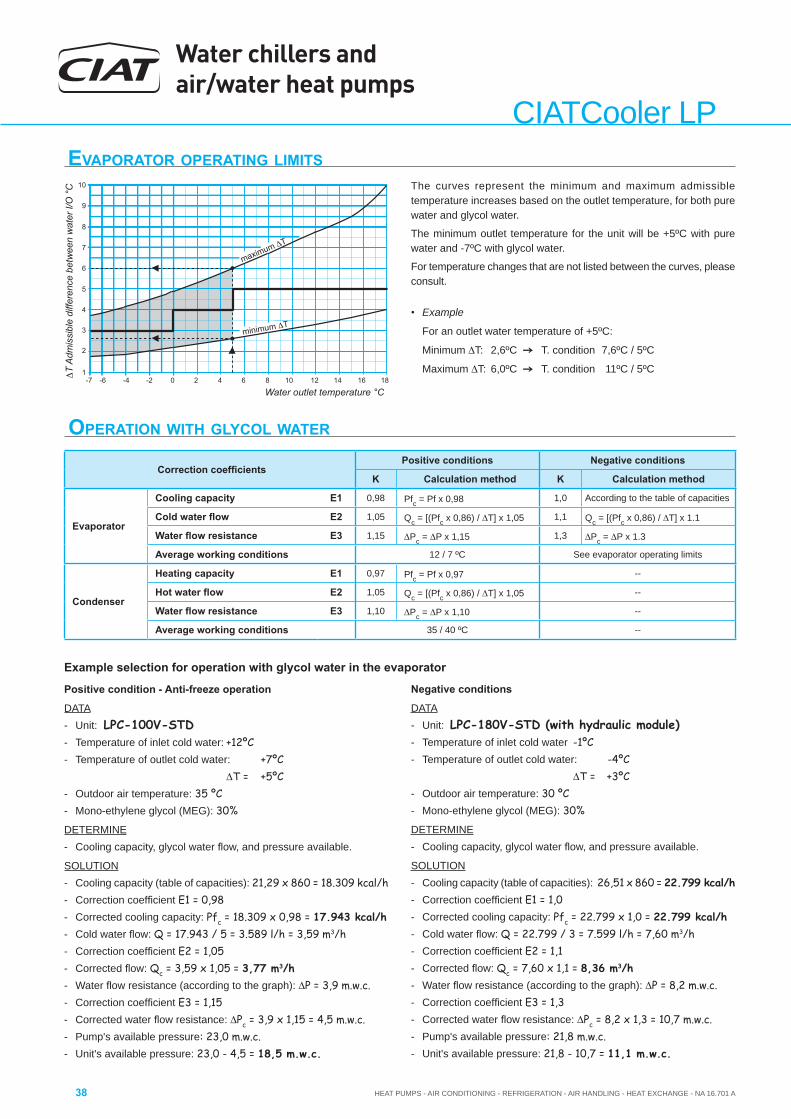
Water chillers and air/water heat pumps
HEAT PUMPS - AIR CONDITIONING - REFRIGERATION - AIR HANDLING - HEAT EXCHANGE - NA 16.701 A38
CIATCooler LP
OPERATION WITH GLYCOL WATER
Correction coeffi cientsPositive conditions Negative conditions
K Calculation method K Calculation method
Evaporator
Cooling capacity E1 0,98 Pfc = Pf x 0,98 1,0 According to the table of capacities
Cold water fl ow E2 1,05 Qc = [(Pfc x 0,86) / T] x 1,05 1,1 Qc = [(Pfc x 0,86) / T] x 1.1
Water fl ow resistance E3 1,15 Pc = P x 1,15 1,3 Pc = P x 1.3
Average working conditions 12 / 7 ºC See evaporator operating limits
Condenser
Heating capacity E1 0,97 Pfc = Pf x 0,97 --
Hot water fl ow E2 1,05 Qc = [(Pfc x 0,86) / T] x 1,05 --
Water fl ow resistance E3 1,10 Pc = P x 1,10 --
Average working conditions 35 / 40 ºC --
EVAPORATOR OPERATING LIMITSThe curves represent the minimum and maximum admissible temperature increases based on the outlet temperature, for both pure water and glycol water.
The minimum outlet temperature for the unit will be +5ºC with pure water and -7ºC with glycol water.
For temperature changes that are not listed between the curves, please consult.
• Example
For an outlet water temperature of +5ºC:
Minimum T: 2,6ºC T. condition 7,6ºC / 5ºC
Maximum T: 6,0ºC T. condition 11ºC / 5ºC
Example selection for operation with glycol water in the evaporator
Positive condition - Anti-freeze operation
DATA- Unit: LPC-100V-STD- Temperature of inlet cold water: +12ºC- Temperature of outlet cold water: +7ºC
T = +5ºC- Outdoor air temperature: 35 ºC- Mono-ethylene glycol (MEG): 30%
DETERMINE- Cooling capacity, glycol water fl ow, and pressure available.
SOLUTION- Cooling capacity (table of capacities): 21,29 x 860 = 18.309 kcal/h- Correction coeffi cient E1 = 0,98- Corrected cooling capacity: Pfc = 18.309 x 0,98 = 17.943 kcal/h- Cold water fl ow: Q = 17.943 / 5 = 3.589 l/h = 3,59 m3/h- Correction coeffi cient E2 = 1,05- Corrected fl ow: Qc = 3,59 x 1,05 = 3,77 m3/h - Water fl ow resistance (according to the graph): P = 3,9 m.w.c.- Correction coeffi cient E3 = 1,15- Corrected water fl ow resistance: Pc = 3,9 x 1,15 = 4,5 m.w.c.- Pump's available pressure: 23,0 m.w.c.- Unit's available pressure: 23,0 - 4,5 = 18,5 m.w.c.
Negative conditions
DATA- Unit: LPC-180V-STD (with hydraulic module)- Temperature of inlet cold water -1ºC- Temperature of outlet cold water: -4ºC
T = +3ºC- Outdoor air temperature: 30 ºC- Mono-ethylene glycol (MEG): 30%
DETERMINE- Cooling capacity, glycol water fl ow, and pressure available.
SOLUTION- Cooling capacity (table of capacities): 26,51 x 860 = 22.799 kcal/h- Correction coeffi cient E1 = 1,0- Corrected cooling capacity: Pfc = 22.799 x 1,0 = 22.799 kcal/h- Cold water fl ow: Q = 22.799 / 3 = 7.599 l/h = 7,60 m3/h- Correction coeffi cient E2 = 1,1- Corrected fl ow: Qc = 7,60 x 1,1 = 8,36 m3/h - Water fl ow resistance (according to the graph): P = 8,2 m.w.c.- Correction coeffi cient E3 = 1,3- Corrected water fl ow resistance: Pc = 8,2 x 1,3 = 10,7 m.w.c.- Pump's available pressure: 21,8 m.w.c.- Unit's available pressure: 21,8 - 10,7 = 11,1 m.w.c.
9
8
7
6
5
4
3
2
1
10
-7 -6 -4 -2 0 2 4 6 8 10 12 14 16 18
Water outlet temperature °C
ΔT
Adm
issi
ble
diffe
renc
e be
twee
n w
ater
I/O
°C
maximum ΔT
minimum ΔT
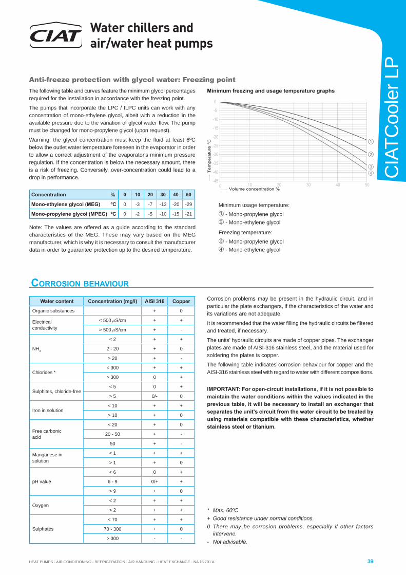
HEAT PUMPS - AIR CONDITIONING - REFRIGERATION - AIR HANDLING - HEAT EXCHANGE - NA 16.701 A
Water chillers and air/water heat pumps
39
CIA
TCoo
ler L
P
Anti-freeze protection with glycol water: Freezing pointThe following table and curves feature the minimum glycol percentages required for the installation in accordance with the freezing point.
The pumps that incorporate the LPC / ILPC units can work with any concentration of mono-ethylene glycol, albeit with a reduction in the available pressure due to the variation of glycol water fl ow. The pump must be changed for mono-propylene glycol (upon request).
Warning: the glycol concentration must keep the fl uid at least 6ºC below the outlet water temperature foreseen in the evaporator in order to allow a correct adjustment of the evaporator's minimum pressure regulation. If the concentration is below the necessary amount, there is a risk of freezing. Conversely, over-concentration could lead to a drop in performance.
-25
-30
-15
-20
-5
-10
0
20 40 5010 30-45
-35
-40
0
34
1
2
Tem
pera
ture
°C
Volume concentration %
Note: The values are offered as a guide according to the standard characteristics of the MEG. These may vary based on the MEG manufacturer, which is why it is necessary to consult the manufacturer data in order to guarantee protection up to the desired temperature.
Minimum freezing and usage temperature graphs
Minimum usage temperature:
- Mono-propylene glycol - Mono-ethylene glycol
Freezing temperature:
- Mono-propylene glycol - Mono-ethylene glycol
Concentration % 0 10 20 30 40 50
Mono-ethylene glycol (MEG) ºC 0 -3 -7 -13 -20 -29
Mono-propylene glycol (MPEG) ºC 0 -2 -5 -10 -15 -21
CORROSION BEHAVIOUR
* Max. 60ºC+ Good resistance under normal conditions.0 There may be corrosion problems, especially if other factors
intervene.- Not advisable.
Corrosion problems may be present in the hydraulic circuit, and in particular the plate exchangers, if the characteristics of the water and its variations are not adequate.
It is recommended that the water fi lling the hydraulic circuits be fi ltered and treated, if necessary.
The units' hydraulic circuits are made of copper pipes. The exchanger plates are made of AISI-316 stainless steel, and the material used for soldering the plates is copper.
The following table indicates corrosion behaviour for copper and the AISI-316 stainless steel with regard to water with different compositions.
IMPORTANT: For open-circuit installations, if it is not possible to maintain the water conditions within the values indicated in the previous table, it will be necessary to install an exchanger that separates the unit's circuit from the water circuit to be treated by using materials compatible with these characteristics, whether stainless steel or titanium.
Water content Concentration (mg/l) AISI 316 Copper
Organic substances + 0
Electricalconductivity
< 500 S/cm + +
> 500 S/cm + -
NH3
< 2 + +
2 - 20 + 0
> 20 + -
Chlorides *< 300 + +
> 300 0 +
Sulphites, chloride-free< 5 0 +
> 5 0/- 0
Iron in solution< 10 + +
> 10 + 0
Free carbonic acid
< 20 + 0
20 - 50 + -
50 + -
Manganese in solution
< 1 + +
> 1 + 0
pH value
< 6 0 +
6 - 9 0/+ +
> 9 + 0
Oxygen< 2 + +
> 2 + +
Sulphates
< 70 + +
70 - 300 + 0
> 300 - -
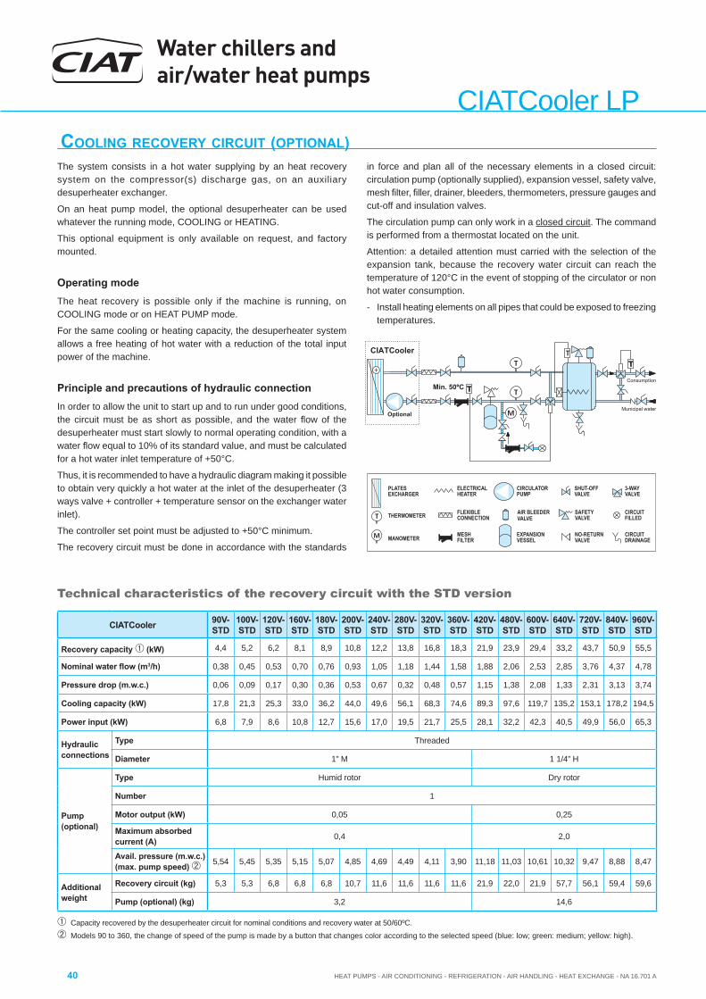
Water chillers and air/water heat pumps
HEAT PUMPS - AIR CONDITIONING - REFRIGERATION - AIR HANDLING - HEAT EXCHANGE - NA 16.701 A40
CIATCooler LPCOOLING RECOVERY CIRCUIT (OPTIONAL)
Capacity recovered by the desuperheater circuit for nominal conditions and recovery water at 50/60ºC.
Models 90 to 360, the change of speed of the pump is made by a button that changes color according to the selected speed (blue: low; green: medium; yellow: high).
The system consists in a hot water supplying by an heat recovery system on the compressor(s) discharge gas, on an auxiliary desuperheater exchanger.
On an heat pump model, the optional desuperheater can be used whatever the running mode, COOLING or HEATING.
This optional equipment is only available on request, and factory mounted.
Operating modeThe heat recovery is possible only if the machine is running, on COOLING mode or on HEAT PUMP mode.
For the same cooling or heating capacity, the desuperheater system allows a free heating of hot water with a reduction of the total input power of the machine.
Principle and precautions of hydraulic connectionIn order to allow the unit to start up and to run under good conditions, the circuit must be as short as possible, and the water fl ow of the desuperheater must start slowly to normal operating condition, with a water fl ow equal to 10% of its standard value, and must be calculated for a hot water inlet temperature of +50°C.
Thus, it is recommended to have a hydraulic diagram making it possible to obtain very quickly a hot water at the inlet of the desuperheater (3 ways valve + controller + temperature sensor on the exchanger water inlet).
The controller set point must be adjusted to +50°C minimum.
The recovery circuit must be done in accordance with the standards
Technical characteristics of the recovery circuit with the STD version
in force and plan all of the necessary elements in a closed circuit: circulation pump (optionally supplied), expansion vessel, safety valve, mesh fi lter, fi ller, drainer, bleeders, thermometers, pressure gauges and cut-off and insulation valves.
The circulation pump can only work in a closed circuit. The command is performed from a thermostat located on the unit.
Attention: a detailed attention must carried with the selection of the expansion tank, because the recovery water circuit can reach the temperature of 120°C in the event of stopping of the circulator or non hot water consumption.
- Install heating elements on all pipes that could be exposed to freezing temperatures.
Municipal water
Consumption
Optional
CIATCooler
Min. 50ºC
PLATESEXCHARGER
EXPANSIONVESSEL
ELECTRICALHEATER
MESHFILTER
VASHUT-OFF
LVE
DRAINAGECIRCUIT
SAFETYVALVE
NO RETURN-VALVE
VAAIR BLEEDER
LVETHERMOMETER
MANOMETER
CIRCULATORPUMP
FILLEDCIRCUIT
3-WAYVALVE
FLEXIBLECONNECTION
CIATCooler 90V-STD
100V-STD
120V-STD
160V-STD
180V-STD
200V-STD
240V-STD
280V-STD
320V-STD
360V-STD
420V-STD
480V-STD
600V-STD
640V-STD
720V-STD
840V-STD
960V-STD
Recovery capacity (kW) 4,4 5,2 6,2 8,1 8,9 10,8 12,2 13,8 16,8 18,3 21,9 23,9 29,4 33,2 43,7 50,9 55,5
Nominal water fl ow (m3/h) 0,38 0,45 0,53 0,70 0,76 0,93 1,05 1,18 1,44 1,58 1,88 2,06 2,53 2,85 3,76 4,37 4,78
Pressure drop (m.w.c.) 0,06 0,09 0,17 0,30 0,36 0,53 0,67 0,32 0,48 0,57 1,15 1,38 2,08 1,33 2,31 3,13 3,74
Cooling capacity (kW) 17,8 21,3 25,3 33,0 36,2 44,0 49,6 56,1 68,3 74,6 89,3 97,6 119,7 135,2 153,1 178,2 194,5
Power input (kW) 6,8 7,9 8,6 10,8 12,7 15,6 17,0 19,5 21,7 25,5 28,1 32,2 42,3 40,5 49,9 56,0 65,3
Hydraulic connections
Type Threaded
Diameter 1” M 1 1/4” H
Pump(optional)
Type Humid rotor Dry rotor
Number 1
Motor output (kW) 0,05 0,25
Maximum absorbed current (A) 0,4 2,0
Avail. pressure (m.w.c.) (max. pump speed) 5,54 5,45 5,35 5,15 5,07 4,85 4,69 4,49 4,11 3,90 11,18 11,03 10,61 10,32 9,47 8,88 8,47
Additional weight
Recovery circuit (kg) 5,3 5,3 6,8 6,8 6,8 10,7 11,6 11,6 11,6 11,6 21,9 22,0 21,9 57,7 56,1 59,4 59,6
Pump (optional) (kg) 3,2 14,6
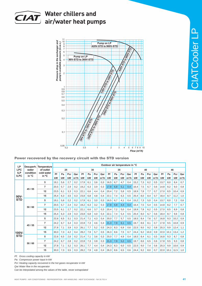
HEAT PUMPS - AIR CONDITIONING - REFRIGERATION - AIR HANDLING - HEAT EXCHANGE - NA 16.701 A
Water chillers and air/water heat pumps
41
CIA
TCoo
ler L
P
Power recovered by the recovery circuit with the STD version
LP LPCILP
ILPC
Desuperh.water
conditionin °C
Temperature of outlet
cold water in ºC
Outdoor air temperature in °C
25 30 35 40 46
Pf Pa Pcr Qar Pf Pa Pcr Qar Pf Pa Pcr Qar Pf Pa Pcr Qar Pf Pa Pcr QarkW kW kW m3/h kW kW kW m3/h kW kW kW m3/h kW kW kW m3/h kW kW kW m3/h
90V-STD
45 / 55
5 19,1 5,6 2,7 0,2 17,9 6,1 3,6 0,3 16,5 6,7 4,7 0,4 15,2 7,3 6,2 0,5 13,7 8,0 8,4 0,7
7 20,5 5,7 2,9 0,2 19,2 6,3 3,9 0,3 17,8 6,8 5,1 0,4 16,4 7,5 6,7 0,6 14,8 8,2 9,0 0,8
12 23,5 6,1 3,3 0,3 22,1 6,6 4,4 0,4 20,4 7,2 5,8 0,5 18,9 7,8 7,7 0,7 17,0 8,5 10,4 0,9
15 25,4 6,3 3,5 0,3 23,8 6,8 4,8 0,4 22,1 7,4 6,3 0,5 20,4 8,0 8,4 0,7 18,4 8,7 11,2 1,0
50 / 60
5 19,1 5,6 2,2 0,2 17,9 6,1 3,0 0,3 16,5 6,7 4,1 0,4 15,2 7,3 5,0 0,4 13,7 8,0 7,2 0,6
7 20,5 5,7 2,4 0,2 19,2 6,3 3,2 0,3 17,8 6,8 4,4 0,4 16,4 7,5 5,4 0,5 14,8 8,2 7,7 0,7
12 23,5 6,1 2,7 0,2 22,1 6,6 3,7 0,3 20,4 7,2 5,0 0,4 18,9 7,8 6,2 0,5 17,0 8,5 8,9 0,8
15 25,4 6,3 2,9 0,3 23,8 6,8 4,0 0,4 22,1 7,4 5,4 0,5 20,4 8,0 6,7 0,6 18,4 8,7 9,6 0,8
100V-STD
45 / 55
5 22,6 6,5 3,1 0,3 21,4 7,1 4,3 0,4 20,0 7,7 5,7 0,5 18,5 8,4 7,6 0,7 16,8 9,3 10,2 0,9
7 24,2 6,7 3,4 0,3 22,8 7,3 4,6 0,4 21,3 7,9 6,1 0,5 19,7 8,6 8,1 0,7 17,8 9,5 10,8 0,9
12 27,8 7,1 3,9 0,3 26,1 7,7 5,2 0,5 24,3 8,3 6,9 0,6 22,5 9,0 9,2 0,8 20,3 9,9 12,4 1,1
15 30,0 7,3 4,2 0,4 28,2 7,9 5,7 0,5 26,3 8,6 7,5 0,7 24,4 9,2 10,0 0,9 22,0 10,1 13,4 1,2
50 / 60
5 22,6 6,5 2,6 0,2 21,4 7,1 3,6 0,3 20,0 7,7 4,9 0,4 18,5 8,4 6,1 0,5 16,8 9,3 8,7 0,8
7 24,2 6,7 2,8 0,2 22,8 7,3 3,8 0,3 21,3 7,9 5,2 0,5 19,7 8,6 6,5 0,6 17,8 9,5 9,3 0,8
12 27,8 7,1 3,2 0,3 26,1 7,7 4,4 0,4 24,3 8,3 6,0 0,5 22,5 9,0 7,4 0,6 20,3 9,9 10,6 0,9
15 30,0 7,3 3,5 0,3 28,2 7,9 4,8 0,4 26,3 8,6 6,5 0,6 24,4 9,2 8,0 0,7 22,0 10,1 11,5 1,0
Pf: Gross cooling capacity in kWPa: Compressor power input in kWPcr: Heating capacity recovered in the hot gases recuperator in kWQar: Water fl ow in the recuperatorCan be interpolated among the values of the table, never extrapolated
1
2
3
4
21
0,60,70,80,9
0,3
0,4
0,5
0,05
0,1
0,2
0,2 0,5
120V
-STD
to 2
40V-
STD
280V
-STD
to 3
60V-
STD
90V-
STD
to 1
00V-
STD
11
6789
5
10
1063 84 5 7 9
420V
-STD
to 6
00V-
STD
640V
-STD
to 9
60V-
STD
Pump on LP 90V-STD to 360V-STD
Pump on LP 420V-STD to 960V-STD
Pres
sure
dro
p in
the
exch
ange
r and
pu
mp’
s av
aila
ble
pres
sure
(m.w
.c.)
Flow (m3/h)
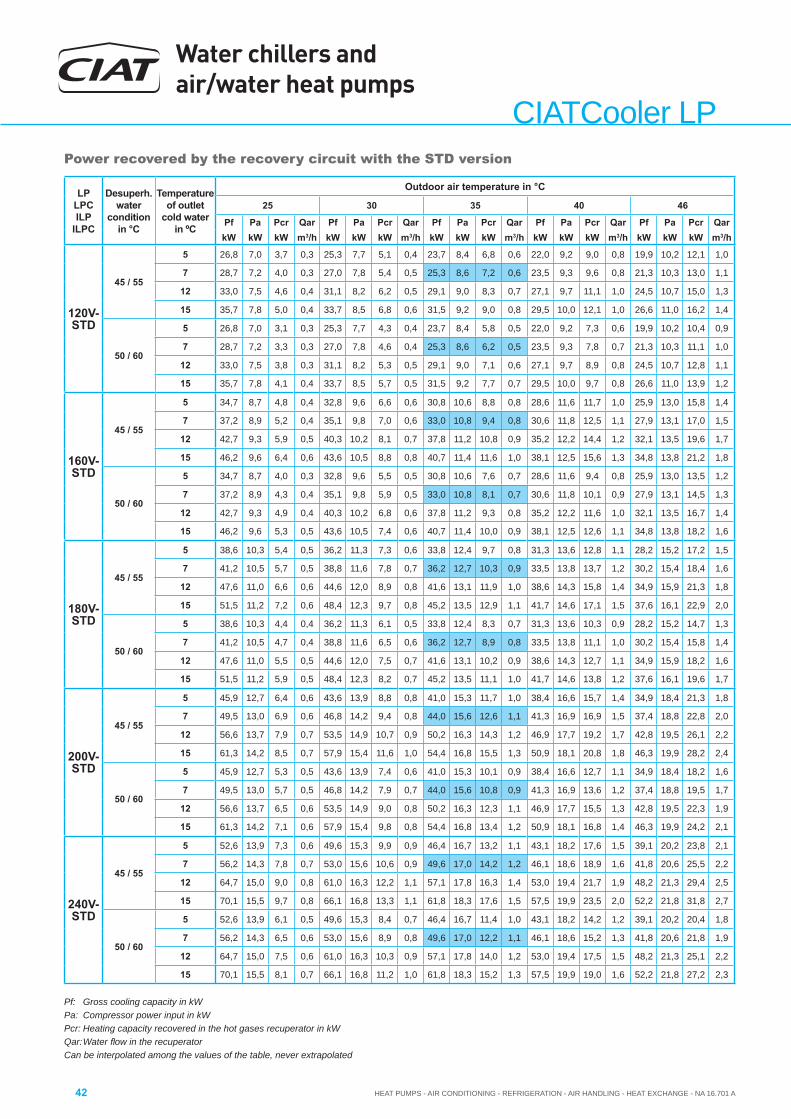
Water chillers and air/water heat pumps
HEAT PUMPS - AIR CONDITIONING - REFRIGERATION - AIR HANDLING - HEAT EXCHANGE - NA 16.701 A42
CIATCooler LPPower recovered by the recovery circuit with the STD version
Pf: Gross cooling capacity in kWPa: Compressor power input in kWPcr: Heating capacity recovered in the hot gases recuperator in kWQar: Water fl ow in the recuperatorCan be interpolated among the values of the table, never extrapolated
LP LPCILP
ILPC
Desuperh.water
conditionin °C
Temperature of outlet
cold water in ºC
Outdoor air temperature in °C
25 30 35 40 46
Pf Pa Pcr Qar Pf Pa Pcr Qar Pf Pa Pcr Qar Pf Pa Pcr Qar Pf Pa Pcr QarkW kW kW m3/h kW kW kW m3/h kW kW kW m3/h kW kW kW m3/h kW kW kW m3/h
120V-STD
45 / 55
5 26,8 7,0 3,7 0,3 25,3 7,7 5,1 0,4 23,7 8,4 6,8 0,6 22,0 9,2 9,0 0,8 19,9 10,2 12,1 1,0
7 28,7 7,2 4,0 0,3 27,0 7,8 5,4 0,5 25,3 8,6 7,2 0,6 23,5 9,3 9,6 0,8 21,3 10,3 13,0 1,1
12 33,0 7,5 4,6 0,4 31,1 8,2 6,2 0,5 29,1 9,0 8,3 0,7 27,1 9,7 11,1 1,0 24,5 10,7 15,0 1,3
15 35,7 7,8 5,0 0,4 33,7 8,5 6,8 0,6 31,5 9,2 9,0 0,8 29,5 10,0 12,1 1,0 26,6 11,0 16,2 1,4
50 / 60
5 26,8 7,0 3,1 0,3 25,3 7,7 4,3 0,4 23,7 8,4 5,8 0,5 22,0 9,2 7,3 0,6 19,9 10,2 10,4 0,9
7 28,7 7,2 3,3 0,3 27,0 7,8 4,6 0,4 25,3 8,6 6,2 0,5 23,5 9,3 7,8 0,7 21,3 10,3 11,1 1,0
12 33,0 7,5 3,8 0,3 31,1 8,2 5,3 0,5 29,1 9,0 7,1 0,6 27,1 9,7 8,9 0,8 24,5 10,7 12,8 1,1
15 35,7 7,8 4,1 0,4 33,7 8,5 5,7 0,5 31,5 9,2 7,7 0,7 29,5 10,0 9,7 0,8 26,6 11,0 13,9 1,2
160V-STD
45 / 55
5 34,7 8,7 4,8 0,4 32,8 9,6 6,6 0,6 30,8 10,6 8,8 0,8 28,6 11,6 11,7 1,0 25,9 13,0 15,8 1,4
7 37,2 8,9 5,2 0,4 35,1 9,8 7,0 0,6 33,0 10,8 9,4 0,8 30,6 11,8 12,5 1,1 27,9 13,1 17,0 1,5
12 42,7 9,3 5,9 0,5 40,3 10,2 8,1 0,7 37,8 11,2 10,8 0,9 35,2 12,2 14,4 1,2 32,1 13,5 19,6 1,7
15 46,2 9,6 6,4 0,6 43,6 10,5 8,8 0,8 40,7 11,4 11,6 1,0 38,1 12,5 15,6 1,3 34,8 13,8 21,2 1,8
50 / 60
5 34,7 8,7 4,0 0,3 32,8 9,6 5,5 0,5 30,8 10,6 7,6 0,7 28,6 11,6 9,4 0,8 25,9 13,0 13,5 1,2
7 37,2 8,9 4,3 0,4 35,1 9,8 5,9 0,5 33,0 10,8 8,1 0,7 30,6 11,8 10,1 0,9 27,9 13,1 14,5 1,3
12 42,7 9,3 4,9 0,4 40,3 10,2 6,8 0,6 37,8 11,2 9,3 0,8 35,2 12,2 11,6 1,0 32,1 13,5 16,7 1,4
15 46,2 9,6 5,3 0,5 43,6 10,5 7,4 0,6 40,7 11,4 10,0 0,9 38,1 12,5 12,6 1,1 34,8 13,8 18,2 1,6
180V-STD
45 / 55
5 38,6 10,3 5,4 0,5 36,2 11,3 7,3 0,6 33,8 12,4 9,7 0,8 31,3 13,6 12,8 1,1 28,2 15,2 17,2 1,5
7 41,2 10,5 5,7 0,5 38,8 11,6 7,8 0,7 36,2 12,7 10,3 0,9 33,5 13,8 13,7 1,2 30,2 15,4 18,4 1,6
12 47,6 11,0 6,6 0,6 44,6 12,0 8,9 0,8 41,6 13,1 11,9 1,0 38,6 14,3 15,8 1,4 34,9 15,9 21,3 1,8
15 51,5 11,2 7,2 0,6 48,4 12,3 9,7 0,8 45,2 13,5 12,9 1,1 41,7 14,6 17,1 1,5 37,6 16,1 22,9 2,0
50 / 60
5 38,6 10,3 4,4 0,4 36,2 11,3 6,1 0,5 33,8 12,4 8,3 0,7 31,3 13,6 10,3 0,9 28,2 15,2 14,7 1,3
7 41,2 10,5 4,7 0,4 38,8 11,6 6,5 0,6 36,2 12,7 8,9 0,8 33,5 13,8 11,1 1,0 30,2 15,4 15,8 1,4
12 47,6 11,0 5,5 0,5 44,6 12,0 7,5 0,7 41,6 13,1 10,2 0,9 38,6 14,3 12,7 1,1 34,9 15,9 18,2 1,6
15 51,5 11,2 5,9 0,5 48,4 12,3 8,2 0,7 45,2 13,5 11,1 1,0 41,7 14,6 13,8 1,2 37,6 16,1 19,6 1,7
200V-STD
45 / 55
5 45,9 12,7 6,4 0,6 43,6 13,9 8,8 0,8 41,0 15,3 11,7 1,0 38,4 16,6 15,7 1,4 34,9 18,4 21,3 1,8
7 49,5 13,0 6,9 0,6 46,8 14,2 9,4 0,8 44,0 15,6 12,6 1,1 41,3 16,9 16,9 1,5 37,4 18,8 22,8 2,0
12 56,6 13,7 7,9 0,7 53,5 14,9 10,7 0,9 50,2 16,3 14,3 1,2 46,9 17,7 19,2 1,7 42,8 19,5 26,1 2,2
15 61,3 14,2 8,5 0,7 57,9 15,4 11,6 1,0 54,4 16,8 15,5 1,3 50,9 18,1 20,8 1,8 46,3 19,9 28,2 2,4
50 / 60
5 45,9 12,7 5,3 0,5 43,6 13,9 7,4 0,6 41,0 15,3 10,1 0,9 38,4 16,6 12,7 1,1 34,9 18,4 18,2 1,6
7 49,5 13,0 5,7 0,5 46,8 14,2 7,9 0,7 44,0 15,6 10,8 0,9 41,3 16,9 13,6 1,2 37,4 18,8 19,5 1,7
12 56,6 13,7 6,5 0,6 53,5 14,9 9,0 0,8 50,2 16,3 12,3 1,1 46,9 17,7 15,5 1,3 42,8 19,5 22,3 1,9
15 61,3 14,2 7,1 0,6 57,9 15,4 9,8 0,8 54,4 16,8 13,4 1,2 50,9 18,1 16,8 1,4 46,3 19,9 24,2 2,1
240V-STD
45 / 55
5 52,6 13,9 7,3 0,6 49,6 15,3 9,9 0,9 46,4 16,7 13,2 1,1 43,1 18,2 17,6 1,5 39,1 20,2 23,8 2,1
7 56,2 14,3 7,8 0,7 53,0 15,6 10,6 0,9 49,6 17,0 14,2 1,2 46,1 18,6 18,9 1,6 41,8 20,6 25,5 2,2
12 64,7 15,0 9,0 0,8 61,0 16,3 12,2 1,1 57,1 17,8 16,3 1,4 53,0 19,4 21,7 1,9 48,2 21,3 29,4 2,5
15 70,1 15,5 9,7 0,8 66,1 16,8 13,3 1,1 61,8 18,3 17,6 1,5 57,5 19,9 23,5 2,0 52,2 21,8 31,8 2,7
50 / 60
5 52,6 13,9 6,1 0,5 49,6 15,3 8,4 0,7 46,4 16,7 11,4 1,0 43,1 18,2 14,2 1,2 39,1 20,2 20,4 1,8
7 56,2 14,3 6,5 0,6 53,0 15,6 8,9 0,8 49,6 17,0 12,2 1,1 46,1 18,6 15,2 1,3 41,8 20,6 21,8 1,9
12 64,7 15,0 7,5 0,6 61,0 16,3 10,3 0,9 57,1 17,8 14,0 1,2 53,0 19,4 17,5 1,5 48,2 21,3 25,1 2,2
15 70,1 15,5 8,1 0,7 66,1 16,8 11,2 1,0 61,8 18,3 15,2 1,3 57,5 19,9 19,0 1,6 52,2 21,8 27,2 2,3
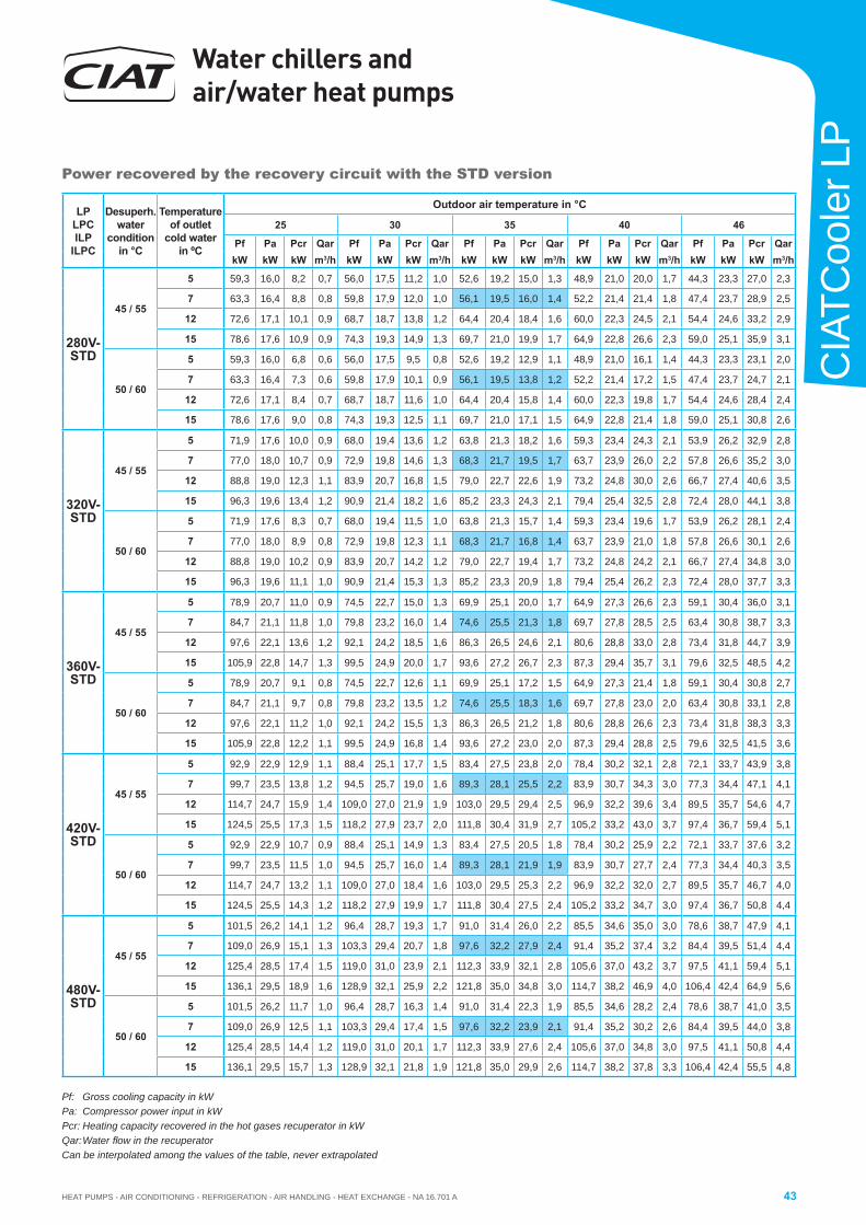
HEAT PUMPS - AIR CONDITIONING - REFRIGERATION - AIR HANDLING - HEAT EXCHANGE - NA 16.701 A
Water chillers and air/water heat pumps
43
CIA
TCoo
ler L
P
Pf: Gross cooling capacity in kWPa: Compressor power input in kWPcr: Heating capacity recovered in the hot gases recuperator in kWQar: Water fl ow in the recuperatorCan be interpolated among the values of the table, never extrapolated
Power recovered by the recovery circuit with the STD version
LP LPCILP
ILPC
Desuperh.water
conditionin °C
Temperature of outlet
cold water in ºC
Outdoor air temperature in °C
25 30 35 40 46
Pf Pa Pcr Qar Pf Pa Pcr Qar Pf Pa Pcr Qar Pf Pa Pcr Qar Pf Pa Pcr QarkW kW kW m3/h kW kW kW m3/h kW kW kW m3/h kW kW kW m3/h kW kW kW m3/h
280V-STD
45 / 55
5 59,3 16,0 8,2 0,7 56,0 17,5 11,2 1,0 52,6 19,2 15,0 1,3 48,9 21,0 20,0 1,7 44,3 23,3 27,0 2,3
7 63,3 16,4 8,8 0,8 59,8 17,9 12,0 1,0 56,1 19,5 16,0 1,4 52,2 21,4 21,4 1,8 47,4 23,7 28,9 2,5
12 72,6 17,1 10,1 0,9 68,7 18,7 13,8 1,2 64,4 20,4 18,4 1,6 60,0 22,3 24,5 2,1 54,4 24,6 33,2 2,9
15 78,6 17,6 10,9 0,9 74,3 19,3 14,9 1,3 69,7 21,0 19,9 1,7 64,9 22,8 26,6 2,3 59,0 25,1 35,9 3,1
50 / 60
5 59,3 16,0 6,8 0,6 56,0 17,5 9,5 0,8 52,6 19,2 12,9 1,1 48,9 21,0 16,1 1,4 44,3 23,3 23,1 2,0
7 63,3 16,4 7,3 0,6 59,8 17,9 10,1 0,9 56,1 19,5 13,8 1,2 52,2 21,4 17,2 1,5 47,4 23,7 24,7 2,1
12 72,6 17,1 8,4 0,7 68,7 18,7 11,6 1,0 64,4 20,4 15,8 1,4 60,0 22,3 19,8 1,7 54,4 24,6 28,4 2,4
15 78,6 17,6 9,0 0,8 74,3 19,3 12,5 1,1 69,7 21,0 17,1 1,5 64,9 22,8 21,4 1,8 59,0 25,1 30,8 2,6
320V-STD
45 / 55
5 71,9 17,6 10,0 0,9 68,0 19,4 13,6 1,2 63,8 21,3 18,2 1,6 59,3 23,4 24,3 2,1 53,9 26,2 32,9 2,8
7 77,0 18,0 10,7 0,9 72,9 19,8 14,6 1,3 68,3 21,7 19,5 1,7 63,7 23,9 26,0 2,2 57,8 26,6 35,2 3,0
12 88,8 19,0 12,3 1,1 83,9 20,7 16,8 1,5 79,0 22,7 22,6 1,9 73,2 24,8 30,0 2,6 66,7 27,4 40,6 3,5
15 96,3 19,6 13,4 1,2 90,9 21,4 18,2 1,6 85,2 23,3 24,3 2,1 79,4 25,4 32,5 2,8 72,4 28,0 44,1 3,8
50 / 60
5 71,9 17,6 8,3 0,7 68,0 19,4 11,5 1,0 63,8 21,3 15,7 1,4 59,3 23,4 19,6 1,7 53,9 26,2 28,1 2,4
7 77,0 18,0 8,9 0,8 72,9 19,8 12,3 1,1 68,3 21,7 16,8 1,4 63,7 23,9 21,0 1,8 57,8 26,6 30,1 2,6
12 88,8 19,0 10,2 0,9 83,9 20,7 14,2 1,2 79,0 22,7 19,4 1,7 73,2 24,8 24,2 2,1 66,7 27,4 34,8 3,0
15 96,3 19,6 11,1 1,0 90,9 21,4 15,3 1,3 85,2 23,3 20,9 1,8 79,4 25,4 26,2 2,3 72,4 28,0 37,7 3,3
360V-STD
45 / 55
5 78,9 20,7 11,0 0,9 74,5 22,7 15,0 1,3 69,9 25,1 20,0 1,7 64,9 27,3 26,6 2,3 59,1 30,4 36,0 3,1
7 84,7 21,1 11,8 1,0 79,8 23,2 16,0 1,4 74,6 25,5 21,3 1,8 69,7 27,8 28,5 2,5 63,4 30,8 38,7 3,3
12 97,6 22,1 13,6 1,2 92,1 24,2 18,5 1,6 86,3 26,5 24,6 2,1 80,6 28,8 33,0 2,8 73,4 31,8 44,7 3,9
15 105,9 22,8 14,7 1,3 99,5 24,9 20,0 1,7 93,6 27,2 26,7 2,3 87,3 29,4 35,7 3,1 79,6 32,5 48,5 4,2
50 / 60
5 78,9 20,7 9,1 0,8 74,5 22,7 12,6 1,1 69,9 25,1 17,2 1,5 64,9 27,3 21,4 1,8 59,1 30,4 30,8 2,7
7 84,7 21,1 9,7 0,8 79,8 23,2 13,5 1,2 74,6 25,5 18,3 1,6 69,7 27,8 23,0 2,0 63,4 30,8 33,1 2,8
12 97,6 22,1 11,2 1,0 92,1 24,2 15,5 1,3 86,3 26,5 21,2 1,8 80,6 28,8 26,6 2,3 73,4 31,8 38,3 3,3
15 105,9 22,8 12,2 1,1 99,5 24,9 16,8 1,4 93,6 27,2 23,0 2,0 87,3 29,4 28,8 2,5 79,6 32,5 41,5 3,6
420V-STD
45 / 55
5 92,9 22,9 12,9 1,1 88,4 25,1 17,7 1,5 83,4 27,5 23,8 2,0 78,4 30,2 32,1 2,8 72,1 33,7 43,9 3,8
7 99,7 23,5 13,8 1,2 94,5 25,7 19,0 1,6 89,3 28,1 25,5 2,2 83,9 30,7 34,3 3,0 77,3 34,4 47,1 4,1
12 114,7 24,7 15,9 1,4 109,0 27,0 21,9 1,9 103,0 29,5 29,4 2,5 96,9 32,2 39,6 3,4 89,5 35,7 54,6 4,7
15 124,5 25,5 17,3 1,5 118,2 27,9 23,7 2,0 111,8 30,4 31,9 2,7 105,2 33,2 43,0 3,7 97,4 36,7 59,4 5,1
50 / 60
5 92,9 22,9 10,7 0,9 88,4 25,1 14,9 1,3 83,4 27,5 20,5 1,8 78,4 30,2 25,9 2,2 72,1 33,7 37,6 3,2
7 99,7 23,5 11,5 1,0 94,5 25,7 16,0 1,4 89,3 28,1 21,9 1,9 83,9 30,7 27,7 2,4 77,3 34,4 40,3 3,5
12 114,7 24,7 13,2 1,1 109,0 27,0 18,4 1,6 103,0 29,5 25,3 2,2 96,9 32,2 32,0 2,7 89,5 35,7 46,7 4,0
15 124,5 25,5 14,3 1,2 118,2 27,9 19,9 1,7 111,8 30,4 27,5 2,4 105,2 33,2 34,7 3,0 97,4 36,7 50,8 4,4
480V-STD
45 / 55
5 101,5 26,2 14,1 1,2 96,4 28,7 19,3 1,7 91,0 31,4 26,0 2,2 85,5 34,6 35,0 3,0 78,6 38,7 47,9 4,1
7 109,0 26,9 15,1 1,3 103,3 29,4 20,7 1,8 97,6 32,2 27,9 2,4 91,4 35,2 37,4 3,2 84,4 39,5 51,4 4,4
12 125,4 28,5 17,4 1,5 119,0 31,0 23,9 2,1 112,3 33,9 32,1 2,8 105,6 37,0 43,2 3,7 97,5 41,1 59,4 5,1
15 136,1 29,5 18,9 1,6 128,9 32,1 25,9 2,2 121,8 35,0 34,8 3,0 114,7 38,2 46,9 4,0 106,4 42,4 64,9 5,6
50 / 60
5 101,5 26,2 11,7 1,0 96,4 28,7 16,3 1,4 91,0 31,4 22,3 1,9 85,5 34,6 28,2 2,4 78,6 38,7 41,0 3,5
7 109,0 26,9 12,5 1,1 103,3 29,4 17,4 1,5 97,6 32,2 23,9 2,1 91,4 35,2 30,2 2,6 84,4 39,5 44,0 3,8
12 125,4 28,5 14,4 1,2 119,0 31,0 20,1 1,7 112,3 33,9 27,6 2,4 105,6 37,0 34,8 3,0 97,5 41,1 50,8 4,4
15 136,1 29,5 15,7 1,3 128,9 32,1 21,8 1,9 121,8 35,0 29,9 2,6 114,7 38,2 37,8 3,3 106,4 42,4 55,5 4,8
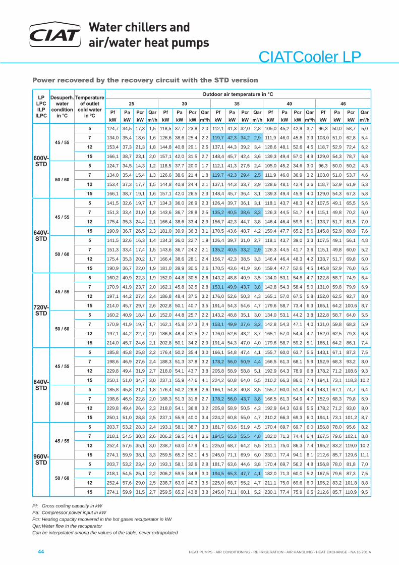
Water chillers and air/water heat pumps
HEAT PUMPS - AIR CONDITIONING - REFRIGERATION - AIR HANDLING - HEAT EXCHANGE - NA 16.701 A44
CIATCooler LP
Pf: Gross cooling capacity in kWPa: Compressor power input in kWPcr: Heating capacity recovered in the hot gases recuperator in kWQar: Water fl ow in the recuperatorCan be interpolated among the values of the table, never extrapolated
Power recovered by the recovery circuit with the STD version
LP LPCILP
ILPC
Desuperh.water
conditionin °C
Temperature of outlet
cold water in ºC
Outdoor air temperature in °C
25 30 35 40 46
Pf Pa Pcr Qar Pf Pa Pcr Qar Pf Pa Pcr Qar Pf Pa Pcr Qar Pf Pa Pcr QarkW kW kW m3/h kW kW kW m3/h kW kW kW m3/h kW kW kW m3/h kW kW kW m3/h
600V-STD
45 / 55
5 124,7 34,5 17,3 1,5 118,5 37,7 23,8 2,0 112,1 41,3 32,0 2,8 105,0 45,2 42,9 3,7 96,3 50,0 58,7 5,0
7 134,0 35,4 18,6 1,6 126,6 38,6 25,4 2,2 119,7 42,3 34,2 2,9 111,9 46,0 45,8 3,9 103,0 51,0 62,8 5,4
12 153,4 37,3 21,3 1,8 144,8 40,8 29,1 2,5 137,1 44,3 39,2 3,4 128,6 48,1 52,6 4,5 118,7 52,9 72,4 6,2
15 166,1 38,7 23,1 2,0 157,1 42,0 31,5 2,7 148,4 45,7 42,4 3,6 139,3 49,4 57,0 4,9 129,0 54,3 78,7 6,8
50 / 60
5 124,7 34,5 14,3 1,2 118,5 37,7 20,0 1,7 112,1 41,3 27,5 2,4 105,0 45,2 34,6 3,0 96,3 50,0 50,2 4,3
7 134,0 35,4 15,4 1,3 126,6 38,6 21,4 1,8 119,7 42,3 29,4 2,5 111,9 46,0 36,9 3,2 103,0 51,0 53,7 4,6
12 153,4 37,3 17,7 1,5 144,8 40,8 24,4 2,1 137,1 44,3 33,7 2,9 128,6 48,1 42,4 3,6 118,7 52,9 61,9 5,3
15 166,1 38,7 19,1 1,6 157,1 42,0 26,5 2,3 148,4 45,7 36,4 3,1 139,3 49,4 45,9 4,0 129,0 54,3 67,3 5,8
640V-STD
45 / 55
5 141,5 32,6 19,7 1,7 134,3 36,0 26,9 2,3 126,4 39,7 36,1 3,1 118,1 43,7 48,3 4,2 107,5 49,1 65,5 5,6
7 151,3 33,4 21,0 1,8 143,6 36,7 28,8 2,5 135,2 40,5 38,6 3,3 126,3 44,5 51,7 4,4 115,1 49,8 70,2 6,0
12 175,4 35,3 24,4 2,1 166,4 38,6 33,4 2,9 156,7 42,3 44,7 3,8 146,4 46,4 59,9 5,1 133,7 51,7 81,5 7,0
15 190,9 36,7 26,5 2,3 181,0 39,9 36,3 3,1 170,5 43,6 48,7 4,2 159,4 47,7 65,2 5,6 145,8 52,9 88,9 7,6
50 / 60
5 141,5 32,6 16,3 1,4 134,3 36,0 22,7 1,9 126,4 39,7 31,0 2,7 118,1 43,7 39,0 3,3 107,5 49,1 56,1 4,8
7 151,3 33,4 17,4 1,5 143,6 36,7 24,2 2,1 135,2 40,5 33,2 2,9 126,3 44,5 41,7 3,6 115,1 49,8 60,0 5,2
12 175,4 35,3 20,2 1,7 166,4 38,6 28,1 2,4 156,7 42,3 38,5 3,3 146,4 46,4 48,3 4,2 133,7 51,7 69,8 6,0
15 190,9 36,7 22,0 1,9 181,0 39,9 30,5 2,6 170,5 43,6 41,9 3,6 159,4 47,7 52,6 4,5 145,8 52,9 76,0 6,5
720V-STD
45 / 55
5 160,2 40,9 22,3 1,9 152,0 44,8 30,5 2,6 143,2 48,8 40,9 3,5 134,0 53,1 54,8 4,7 122,8 58,7 74,9 6,4
7 170,9 41,9 23,7 2,0 162,1 45,8 32,5 2,8 153,1 49,9 43,7 3,8 142,8 54,3 58,4 5,0 131,0 59,8 79,9 6,9
12 197,1 44,2 27,4 2,4 186,8 48,4 37,5 3,2 176,0 52,6 50,3 4,3 165,1 57,0 67,5 5,8 152,0 62,5 92,7 8,0
15 214,0 45,7 29,7 2,6 202,8 50,1 40,7 3,5 191,4 54,3 54,6 4,7 179,6 58,7 73,4 6,3 165,1 64,2 100,6 8,7
50 / 60
5 160,2 40,9 18,4 1,6 152,0 44,8 25,7 2,2 143,2 48,8 35,1 3,0 134,0 53,1 44,2 3,8 122,8 58,7 64,0 5,5
7 170,9 41,9 19,7 1,7 162,1 45,8 27,3 2,4 153,1 49,9 37,6 3,2 142,8 54,3 47,1 4,0 131,0 59,8 68,3 5,9
12 197,1 44,2 22,7 2,0 186,8 48,4 31,5 2,7 176,0 52,6 43,2 3,7 165,1 57,0 54,4 4,7 152,0 62,5 79,3 6,8
15 214,0 45,7 24,6 2,1 202,8 50,1 34,2 2,9 191,4 54,3 47,0 4,0 179,6 58,7 59,2 5,1 165,1 64,2 86,1 7,4
840V-STD
45 / 55
5 185,8 45,8 25,8 2,2 176,4 50,2 35,4 3,0 166,1 54,8 47,4 4,1 155,7 60,0 63,7 5,5 143,1 67,1 87,3 7,5
7 198,6 46,9 27,6 2,4 188,3 51,3 37,8 3,2 178,2 56,0 50,9 4,4 166,5 61,3 68,1 5,9 152,9 68,3 93,2 8,0
12 229,8 49,4 31,9 2,7 218,0 54,1 43,7 3,8 205,8 58,9 58,8 5,1 192,9 64,3 78,9 6,8 178,2 71,2 108,6 9,3
15 250,1 51,0 34,7 3,0 237,1 55,9 47,6 4,1 224,2 60,8 64,0 5,5 210,2 66,3 86,0 7,4 194,1 73,1 118,3 10,2
50 / 60
5 185,8 45,8 21,4 1,8 176,4 50,2 29,8 2,6 166,1 54,8 40,8 3,5 155,7 60,0 51,4 4,4 143,1 67,1 74,7 6,4
7 198,6 46,9 22,8 2,0 188,3 51,3 31,8 2,7 178,2 56,0 43,7 3,8 166,5 61,3 54,9 4,7 152,9 68,3 79,8 6,9
12 229,8 49,4 26,4 2,3 218,0 54,1 36,8 3,2 205,8 58,9 50,5 4,3 192,9 64,3 63,6 5,5 178,2 71,2 93,0 8,0
15 250,1 51,0 28,8 2,5 237,1 55,9 40,0 3,4 224,2 60,8 55,0 4,7 210,2 66,3 69,3 6,0 194,1 73,1 101,2 8,7
960V-STD
45 / 55
5 203,7 53,2 28,3 2,4 193,1 58,1 38,7 3,3 181,7 63,6 51,9 4,5 170,4 69,7 69,7 6,0 156,8 78,0 95,6 8,2
7 218,1 54,5 30,3 2,6 206,2 59,5 41,4 3,6 194,5 65,3 55,5 4,8 182,0 71,3 74,4 6,4 167,5 79,6 102,1 8,8
12 252,4 57,6 35,1 3,0 238,7 63,0 47,9 4,1 225,0 68,7 64,2 5,5 211,1 75,0 86,3 7,4 195,2 83,2 119,0 10,2
15 274,1 59,9 38,1 3,3 259,5 65,2 52,1 4,5 245,0 71,1 69,9 6,0 230,1 77,4 94,1 8,1 212,6 85,7 129,6 11,1
50 / 60
5 203,7 53,2 23,4 2,0 193,1 58,1 32,6 2,8 181,7 63,6 44,6 3,8 170,4 69,7 56,2 4,8 156,8 78,0 81,8 7,0
7 218,1 54,5 25,1 2,2 206,2 59,5 34,8 3,0 194,5 65,3 47,7 4,1 182,0 71,3 60,0 5,2 167,5 79,6 87,3 7,5
12 252,4 57,6 29,0 2,5 238,7 63,0 40,3 3,5 225,0 68,7 55,2 4,7 211,1 75,0 69,6 6,0 195,2 83,2 101,8 8,8
15 274,1 59,9 31,5 2,7 259,5 65,2 43,8 3,8 245,0 71,1 60,1 5,2 230,1 77,4 75,9 6,5 212,6 85,7 110,9 9,5
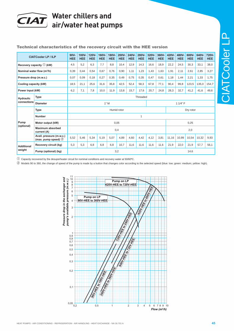
HEAT PUMPS - AIR CONDITIONING - REFRIGERATION - AIR HANDLING - HEAT EXCHANGE - NA 16.701 A
Water chillers and air/water heat pumps
45
CIA
TCoo
ler L
P
Capacity recovered by the desuperheater circuit for nominal conditions and recovery water at 50/60ºC.
Models 90 to 360, the change of speed of the pump is made by a button that changes color according to the selected speed (blue: low; green: medium; yellow: high).
1
2
3
4
21
0,60,70,80,9
0,3
0,4
0,5
0,05
0,1
0,2
0,2 0,5
120V
-HEE
to 2
40V-
HEE
280V
-HEE
to 3
60V-
HEE
90V-
HEE
to 1
00V-
HEE
11
6789
5
10
1063 84 5 7 9
420V
-HEE
to 6
00V-
HEE
640V
-HEE
to 7
20V-
HEE
Pump on LP 90V-HEE to 360V-HEE
Pump on LP 420V-HEE to 720V-HEE
Pres
sure
dro
p in
the
exch
ange
r and
pu
mp’
s av
aila
ble
pres
sure
(m.w
.c.)
Flow (m3/h)
Technical characteristics of the recovery circuit with the HEE version
CIATCooler LP / ILP 90V-HEE
100V-HEE
120V-HEE
160V-HEE
180V-HEE
200V-HEE
240V-HEE
280V-HEE
320V-HEE
360V-HEE
420V-HEE
480V-HEE
600V-HEE
640V-HEE
720V-HEE
Recovery capacity (kW) 4,5 5,2 6,3 7,7 8,8 10,4 12,9 14,3 16,6 18,9 22,2 24,5 30,3 33,1 38,0
Nominal water fl ow (m3/h) 0,39 0,44 0,54 0,67 0,76 0,90 1,11 1,23 1,43 1,63 1,91 2,11 2,61 2,85 3,27
Pressure drop (m.w.c.) 0,07 0,09 0,18 0,27 0,35 0,49 0,75 0,35 0,47 0,61 1,18 1,44 2,21 1,33 1,75
Cooling capacity (kW) 18,5 21,1 25,6 31,6 35,8 42,5 52,4 58,3 67,8 77,1 90,4 99,8 123,5 135,0 154,7
Power input (kW) 6,2 7,1 7,8 10,0 11,9 13,8 15,7 17,6 20,7 24,8 28,3 32,7 41,2 41,6 49,6
Hydraulic connections
Type Threaded
Diameter 1” M 1 1/4” F
Pump(optional)
Type Humid rotor Dry rotor
Number 1
Motor output (kW) 0,05 0,25
Maximum absorbed current (A) 0,4 2,0
Avail. pressure (m.w.c.) (max. pump speed) 5,52 5,46 5,34 5,19 5,07 4,89 4,60 4,42 4,12 3,81 11,16 10,99 10,54 10,32 9,93
Additional weight
Recovery circuit (kg) 5,3 5,3 6,8 6,8 6,8 10,7 11,6 11,6 11,6 11,6 21,9 22,0 21,9 57,7 56,1
Pump (optional) (kg) 3,2 14,6
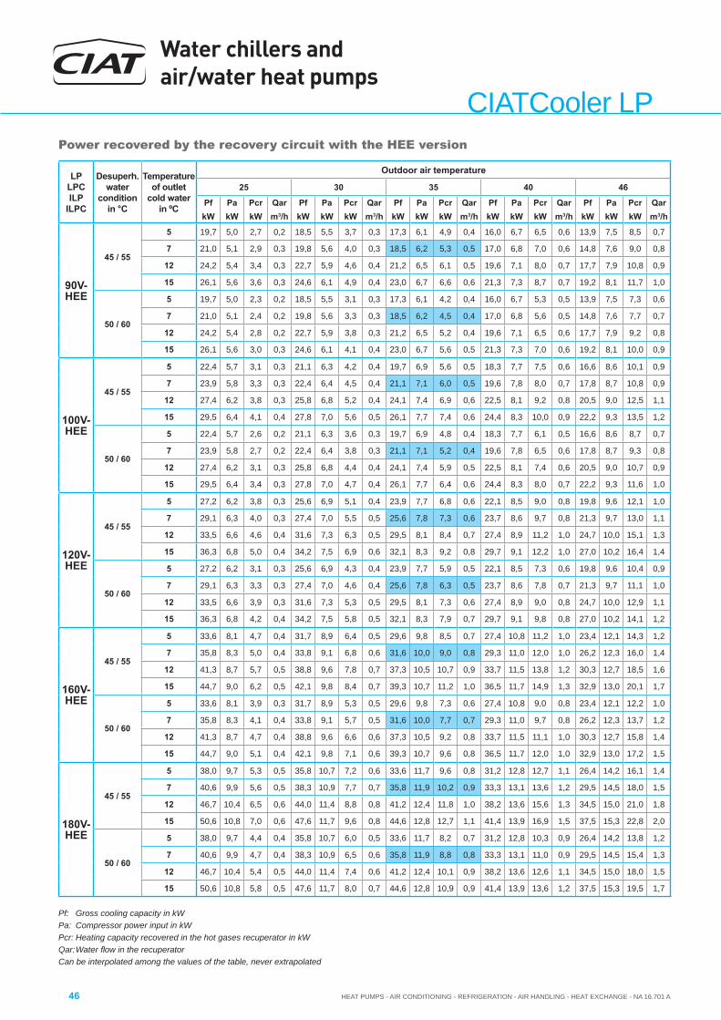
Water chillers and air/water heat pumps
HEAT PUMPS - AIR CONDITIONING - REFRIGERATION - AIR HANDLING - HEAT EXCHANGE - NA 16.701 A46
CIATCooler LPPower recovered by the recovery circuit with the HEE version
LP LPCILP
ILPC
Desuperh.water
conditionin °C
Temperature of outlet
cold water in ºC
Outdoor air temperature
25 30 35 40 46
Pf Pa Pcr Qar Pf Pa Pcr Qar Pf Pa Pcr Qar Pf Pa Pcr Qar Pf Pa Pcr QarkW kW kW m3/h kW kW kW m3/h kW kW kW m3/h kW kW kW m3/h kW kW kW m3/h
90V-HEE
45 / 55
5 19,7 5,0 2,7 0,2 18,5 5,5 3,7 0,3 17,3 6,1 4,9 0,4 16,0 6,7 6,5 0,6 13,9 7,5 8,5 0,7
7 21,0 5,1 2,9 0,3 19,8 5,6 4,0 0,3 18,5 6,2 5,3 0,5 17,0 6,8 7,0 0,6 14,8 7,6 9,0 0,8
12 24,2 5,4 3,4 0,3 22,7 5,9 4,6 0,4 21,2 6,5 6,1 0,5 19,6 7,1 8,0 0,7 17,7 7,9 10,8 0,9
15 26,1 5,6 3,6 0,3 24,6 6,1 4,9 0,4 23,0 6,7 6,6 0,6 21,3 7,3 8,7 0,7 19,2 8,1 11,7 1,0
50 / 60
5 19,7 5,0 2,3 0,2 18,5 5,5 3,1 0,3 17,3 6,1 4,2 0,4 16,0 6,7 5,3 0,5 13,9 7,5 7,3 0,6
7 21,0 5,1 2,4 0,2 19,8 5,6 3,3 0,3 18,5 6,2 4,5 0,4 17,0 6,8 5,6 0,5 14,8 7,6 7,7 0,7
12 24,2 5,4 2,8 0,2 22,7 5,9 3,8 0,3 21,2 6,5 5,2 0,4 19,6 7,1 6,5 0,6 17,7 7,9 9,2 0,8
15 26,1 5,6 3,0 0,3 24,6 6,1 4,1 0,4 23,0 6,7 5,6 0,5 21,3 7,3 7,0 0,6 19,2 8,1 10,0 0,9
100V-HEE
45 / 55
5 22,4 5,7 3,1 0,3 21,1 6,3 4,2 0,4 19,7 6,9 5,6 0,5 18,3 7,7 7,5 0,6 16,6 8,6 10,1 0,9
7 23,9 5,8 3,3 0,3 22,4 6,4 4,5 0,4 21,1 7,1 6,0 0,5 19,6 7,8 8,0 0,7 17,8 8,7 10,8 0,9
12 27,4 6,2 3,8 0,3 25,8 6,8 5,2 0,4 24,1 7,4 6,9 0,6 22,5 8,1 9,2 0,8 20,5 9,0 12,5 1,1
15 29,5 6,4 4,1 0,4 27,8 7,0 5,6 0,5 26,1 7,7 7,4 0,6 24,4 8,3 10,0 0,9 22,2 9,3 13,5 1,2
50 / 60
5 22,4 5,7 2,6 0,2 21,1 6,3 3,6 0,3 19,7 6,9 4,8 0,4 18,3 7,7 6,1 0,5 16,6 8,6 8,7 0,7
7 23,9 5,8 2,7 0,2 22,4 6,4 3,8 0,3 21,1 7,1 5,2 0,4 19,6 7,8 6,5 0,6 17,8 8,7 9,3 0,8
12 27,4 6,2 3,1 0,3 25,8 6,8 4,4 0,4 24,1 7,4 5,9 0,5 22,5 8,1 7,4 0,6 20,5 9,0 10,7 0,9
15 29,5 6,4 3,4 0,3 27,8 7,0 4,7 0,4 26,1 7,7 6,4 0,6 24,4 8,3 8,0 0,7 22,2 9,3 11,6 1,0
120V-HEE
45 / 55
5 27,2 6,2 3,8 0,3 25,6 6,9 5,1 0,4 23,9 7,7 6,8 0,6 22,1 8,5 9,0 0,8 19,8 9,6 12,1 1,0
7 29,1 6,3 4,0 0,3 27,4 7,0 5,5 0,5 25,6 7,8 7,3 0,6 23,7 8,6 9,7 0,8 21,3 9,7 13,0 1,1
12 33,5 6,6 4,6 0,4 31,6 7,3 6,3 0,5 29,5 8,1 8,4 0,7 27,4 8,9 11,2 1,0 24,7 10,0 15,1 1,3
15 36,3 6,8 5,0 0,4 34,2 7,5 6,9 0,6 32,1 8,3 9,2 0,8 29,7 9,1 12,2 1,0 27,0 10,2 16,4 1,4
50 / 60
5 27,2 6,2 3,1 0,3 25,6 6,9 4,3 0,4 23,9 7,7 5,9 0,5 22,1 8,5 7,3 0,6 19,8 9,6 10,4 0,9
7 29,1 6,3 3,3 0,3 27,4 7,0 4,6 0,4 25,6 7,8 6,3 0,5 23,7 8,6 7,8 0,7 21,3 9,7 11,1 1,0
12 33,5 6,6 3,9 0,3 31,6 7,3 5,3 0,5 29,5 8,1 7,3 0,6 27,4 8,9 9,0 0,8 24,7 10,0 12,9 1,1
15 36,3 6,8 4,2 0,4 34,2 7,5 5,8 0,5 32,1 8,3 7,9 0,7 29,7 9,1 9,8 0,8 27,0 10,2 14,1 1,2
160V-HEE
45 / 55
5 33,6 8,1 4,7 0,4 31,7 8,9 6,4 0,5 29,6 9,8 8,5 0,7 27,4 10,8 11,2 1,0 23,4 12,1 14,3 1,2
7 35,8 8,3 5,0 0,4 33,8 9,1 6,8 0,6 31,6 10,0 9,0 0,8 29,3 11,0 12,0 1,0 26,2 12,3 16,0 1,4
12 41,3 8,7 5,7 0,5 38,8 9,6 7,8 0,7 37,3 10,5 10,7 0,9 33,7 11,5 13,8 1,2 30,3 12,7 18,5 1,6
15 44,7 9,0 6,2 0,5 42,1 9,8 8,4 0,7 39,3 10,7 11,2 1,0 36,5 11,7 14,9 1,3 32,9 13,0 20,1 1,7
50 / 60
5 33,6 8,1 3,9 0,3 31,7 8,9 5,3 0,5 29,6 9,8 7,3 0,6 27,4 10,8 9,0 0,8 23,4 12,1 12,2 1,0
7 35,8 8,3 4,1 0,4 33,8 9,1 5,7 0,5 31,6 10,0 7,7 0,7 29,3 11,0 9,7 0,8 26,2 12,3 13,7 1,2
12 41,3 8,7 4,7 0,4 38,8 9,6 6,6 0,6 37,3 10,5 9,2 0,8 33,7 11,5 11,1 1,0 30,3 12,7 15,8 1,4
15 44,7 9,0 5,1 0,4 42,1 9,8 7,1 0,6 39,3 10,7 9,6 0,8 36,5 11,7 12,0 1,0 32,9 13,0 17,2 1,5
180V-HEE
45 / 55
5 38,0 9,7 5,3 0,5 35,8 10,7 7,2 0,6 33,6 11,7 9,6 0,8 31,2 12,8 12,7 1,1 26,4 14,2 16,1 1,4
7 40,6 9,9 5,6 0,5 38,3 10,9 7,7 0,7 35,8 11,9 10,2 0,9 33,3 13,1 13,6 1,2 29,5 14,5 18,0 1,5
12 46,7 10,4 6,5 0,6 44,0 11,4 8,8 0,8 41,2 12,4 11,8 1,0 38,2 13,6 15,6 1,3 34,5 15,0 21,0 1,8
15 50,6 10,8 7,0 0,6 47,6 11,7 9,6 0,8 44,6 12,8 12,7 1,1 41,4 13,9 16,9 1,5 37,5 15,3 22,8 2,0
50 / 60
5 38,0 9,7 4,4 0,4 35,8 10,7 6,0 0,5 33,6 11,7 8,2 0,7 31,2 12,8 10,3 0,9 26,4 14,2 13,8 1,2
7 40,6 9,9 4,7 0,4 38,3 10,9 6,5 0,6 35,8 11,9 8,8 0,8 33,3 13,1 11,0 0,9 29,5 14,5 15,4 1,3
12 46,7 10,4 5,4 0,5 44,0 11,4 7,4 0,6 41,2 12,4 10,1 0,9 38,2 13,6 12,6 1,1 34,5 15,0 18,0 1,5
15 50,6 10,8 5,8 0,5 47,6 11,7 8,0 0,7 44,6 12,8 10,9 0,9 41,4 13,9 13,6 1,2 37,5 15,3 19,5 1,7
Pf: Gross cooling capacity in kWPa: Compressor power input in kWPcr: Heating capacity recovered in the hot gases recuperator in kWQar: Water fl ow in the recuperatorCan be interpolated among the values of the table, never extrapolated
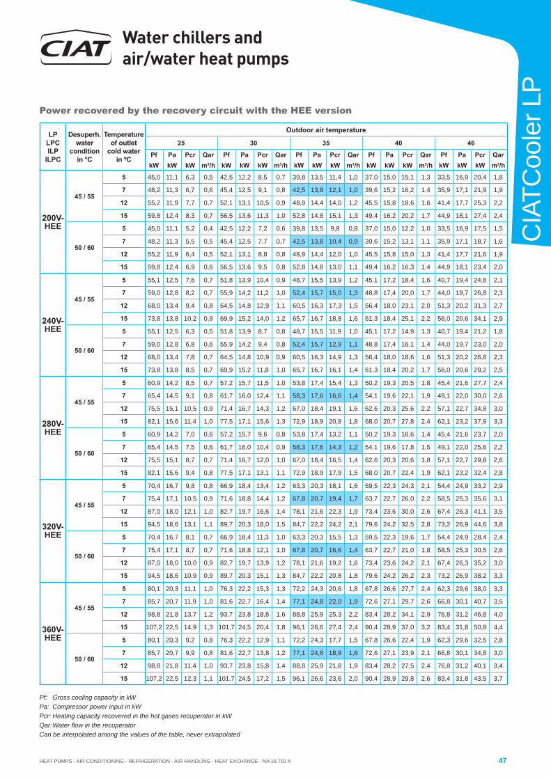
HEAT PUMPS - AIR CONDITIONING - REFRIGERATION - AIR HANDLING - HEAT EXCHANGE - NA 16.701 A
Water chillers and air/water heat pumps
47
CIA
TCoo
ler L
P
Power recovered by the recovery circuit with the HEE version
LP LPCILP
ILPC
Desuperh.water
conditionin °C
Temperature of outlet
cold water in ºC
Outdoor air temperature
25 30 35 40 46
Pf Pa Pcr Qar Pf Pa Pcr Qar Pf Pa Pcr Qar Pf Pa Pcr Qar Pf Pa Pcr QarkW kW kW m3/h kW kW kW m3/h kW kW kW m3/h kW kW kW m3/h kW kW kW m3/h
200V-HEE
45 / 55
5 45,0 11,1 6,3 0,5 42,5 12,2 8,5 0,7 39,8 13,5 11,4 1,0 37,0 15,0 15,1 1,3 33,5 16,9 20,4 1,8
7 48,2 11,3 6,7 0,6 45,4 12,5 9,1 0,8 42,5 13,8 12,1 1,0 39,6 15,2 16,2 1,4 35,9 17,1 21,9 1,9
12 55,2 11,9 7,7 0,7 52,1 13,1 10,5 0,9 48,9 14,4 14,0 1,2 45,5 15,8 18,6 1,6 41,4 17,7 25,3 2,2
15 59,8 12,4 8,3 0,7 56,5 13,6 11,3 1,0 52,8 14,8 15,1 1,3 49,4 16,2 20,2 1,7 44,9 18,1 27,4 2,4
50 / 60
5 45,0 11,1 5,2 0,4 42,5 12,2 7,2 0,6 39,8 13,5 9,8 0,8 37,0 15,0 12,2 1,0 33,5 16,9 17,5 1,5
7 48,2 11,3 5,5 0,5 45,4 12,5 7,7 0,7 42,5 13,8 10,4 0,9 39,6 15,2 13,1 1,1 35,9 17,1 18,7 1,6
12 55,2 11,9 6,4 0,5 52,1 13,1 8,8 0,8 48,9 14,4 12,0 1,0 45,5 15,8 15,0 1,3 41,4 17,7 21,6 1,9
15 59,8 12,4 6,9 0,6 56,5 13,6 9,5 0,8 52,8 14,8 13,0 1,1 49,4 16,2 16,3 1,4 44,9 18,1 23,4 2,0
240V-HEE
45 / 55
5 55,1 12,5 7,6 0,7 51,8 13,9 10,4 0,9 48,7 15,5 13,9 1,2 45,1 17,2 18,4 1,6 40,7 19,4 24,8 2,1
7 59,0 12,8 8,2 0,7 55,9 14,2 11,2 1,0 52,4 15,7 15,0 1,3 48,8 17,4 20,0 1,7 44,0 19,7 26,8 2,3
12 68,0 13,4 9,4 0,8 64,5 14,8 12,9 1,1 60,5 16,3 17,3 1,5 56,4 18,0 23,1 2,0 51,3 20,2 31,3 2,7
15 73,8 13,8 10,2 0,9 69,9 15,2 14,0 1,2 65,7 16,7 18,8 1,6 61,3 18,4 25,1 2,2 56,0 20,6 34,1 2,9
50 / 60
5 55,1 12,5 6,3 0,5 51,8 13,9 8,7 0,8 48,7 15,5 11,9 1,0 45,1 17,2 14,9 1,3 40,7 19,4 21,2 1,8
7 59,0 12,8 6,8 0,6 55,9 14,2 9,4 0,8 52,4 15,7 12,9 1,1 48,8 17,4 16,1 1,4 44,0 19,7 23,0 2,0
12 68,0 13,4 7,8 0,7 64,5 14,8 10,9 0,9 60,5 16,3 14,9 1,3 56,4 18,0 18,6 1,6 51,3 20,2 26,8 2,3
15 73,8 13,8 8,5 0,7 69,9 15,2 11,8 1,0 65,7 16,7 16,1 1,4 61,3 18,4 20,2 1,7 56,0 20,6 29,2 2,5
280V-HEE
45 / 55
5 60,9 14,2 8,5 0,7 57,2 15,7 11,5 1,0 53,8 17,4 15,4 1,3 50,2 19,3 20,5 1,8 45,4 21,6 27,7 2,4
7 65,4 14,5 9,1 0,8 61,7 16,0 12,4 1,1 58,3 17,6 16,6 1,4 54,1 19,6 22,1 1,9 49,1 22,0 30,0 2,6
12 75,5 15,1 10,5 0,9 71,4 16,7 14,3 1,2 67,0 18,4 19,1 1,6 62,6 20,3 25,6 2,2 57,1 22,7 34,8 3,0
15 82,1 15,6 11,4 1,0 77,5 17,1 15,6 1,3 72,9 18,9 20,8 1,8 68,0 20,7 27,8 2,4 62,1 23,2 37,9 3,3
50 / 60
5 60,9 14,2 7,0 0,6 57,2 15,7 9,6 0,8 53,8 17,4 13,2 1,1 50,2 19,3 16,6 1,4 45,4 21,6 23,7 2,0
7 65,4 14,5 7,5 0,6 61,7 16,0 10,4 0,9 58,3 17,6 14,3 1,2 54,1 19,6 17,8 1,5 49,1 22,0 25,6 2,2
12 75,5 15,1 8,7 0,7 71,4 16,7 12,0 1,0 67,0 18,4 16,5 1,4 62,6 20,3 20,6 1,8 57,1 22,7 29,8 2,6
15 82,1 15,6 9,4 0,8 77,5 17,1 13,1 1,1 72,9 18,9 17,9 1,5 68,0 20,7 22,4 1,9 62,1 23,2 32,4 2,8
320V-HEE
45 / 55
5 70,4 16,7 9,8 0,8 66,9 18,4 13,4 1,2 63,3 20,3 18,1 1,6 59,5 22,3 24,3 2,1 54,4 24,9 33,2 2,9
7 75,4 17,1 10,5 0,9 71,6 18,8 14,4 1,2 67,8 20,7 19,4 1,7 63,7 22,7 26,0 2,2 58,5 25,3 35,6 3,1
12 87,0 18,0 12,1 1,0 82,7 19,7 16,6 1,4 78,1 21,6 22,3 1,9 73,4 23,6 30,0 2,6 67,4 26,3 41,1 3,5
15 94,5 18,6 13,1 1,1 89,7 20,3 18,0 1,5 84,7 22,2 24,2 2,1 79,6 24,2 32,5 2,8 73,2 26,9 44,6 3,8
50 / 60
5 70,4 16,7 8,1 0,7 66,9 18,4 11,3 1,0 63,3 20,3 15,5 1,3 59,5 22,3 19,6 1,7 54,4 24,9 28,4 2,4
7 75,4 17,1 8,7 0,7 71,6 18,8 12,1 1,0 67,8 20,7 16,6 1,4 63,7 22,7 21,0 1,8 58,5 25,3 30,5 2,6
12 87,0 18,0 10,0 0,9 82,7 19,7 13,9 1,2 78,1 21,6 19,2 1,6 73,4 23,6 24,2 2,1 67,4 26,3 35,2 3,0
15 94,5 18,6 10,9 0,9 89,7 20,3 15,1 1,3 84,7 22,2 20,8 1,8 79,6 24,2 26,2 2,3 73,2 26,9 38,2 3,3
360V-HEE
45 / 55
5 80,1 20,3 11,1 1,0 76,3 22,2 15,3 1,3 72,2 24,3 20,6 1,8 67,8 26,6 27,7 2,4 62,3 29,6 38,0 3,3
7 85,7 20,7 11,9 1,0 81,6 22,7 16,4 1,4 77,1 24,8 22,0 1,9 72,6 27,1 29,7 2,6 66,8 30,1 40,7 3,5
12 98,8 21,8 13,7 1,2 93,7 23,8 18,8 1,6 88,8 25,9 25,3 2,2 83,4 28,2 34,1 2,9 76,8 31,2 46,8 4,0
15 107,2 22,5 14,9 1,3 101,7 24,5 20,4 1,8 96,1 26,6 27,4 2,4 90,4 28,9 37,0 3,2 83,4 31,8 50,8 4,4
50 / 60
5 80,1 20,3 9,2 0,8 76,3 22,2 12,9 1,1 72,2 24,3 17,7 1,5 67,8 26,6 22,4 1,9 62,3 29,6 32,5 2,8
7 85,7 20,7 9,9 0,8 81,6 22,7 13,8 1,2 77,1 24,8 18,9 1,6 72,6 27,1 23,9 2,1 66,8 30,1 34,8 3,0
12 98,8 21,8 11,4 1,0 93,7 23,8 15,8 1,4 88,8 25,9 21,8 1,9 83,4 28,2 27,5 2,4 76,8 31,2 40,1 3,4
15 107,2 22,5 12,3 1,1 101,7 24,5 17,2 1,5 96,1 26,6 23,6 2,0 90,4 28,9 29,8 2,6 83,4 31,8 43,5 3,7
Pf: Gross cooling capacity in kWPa: Compressor power input in kWPcr: Heating capacity recovered in the hot gases recuperator in kWQar: Water fl ow in the recuperatorCan be interpolated among the values of the table, never extrapolated
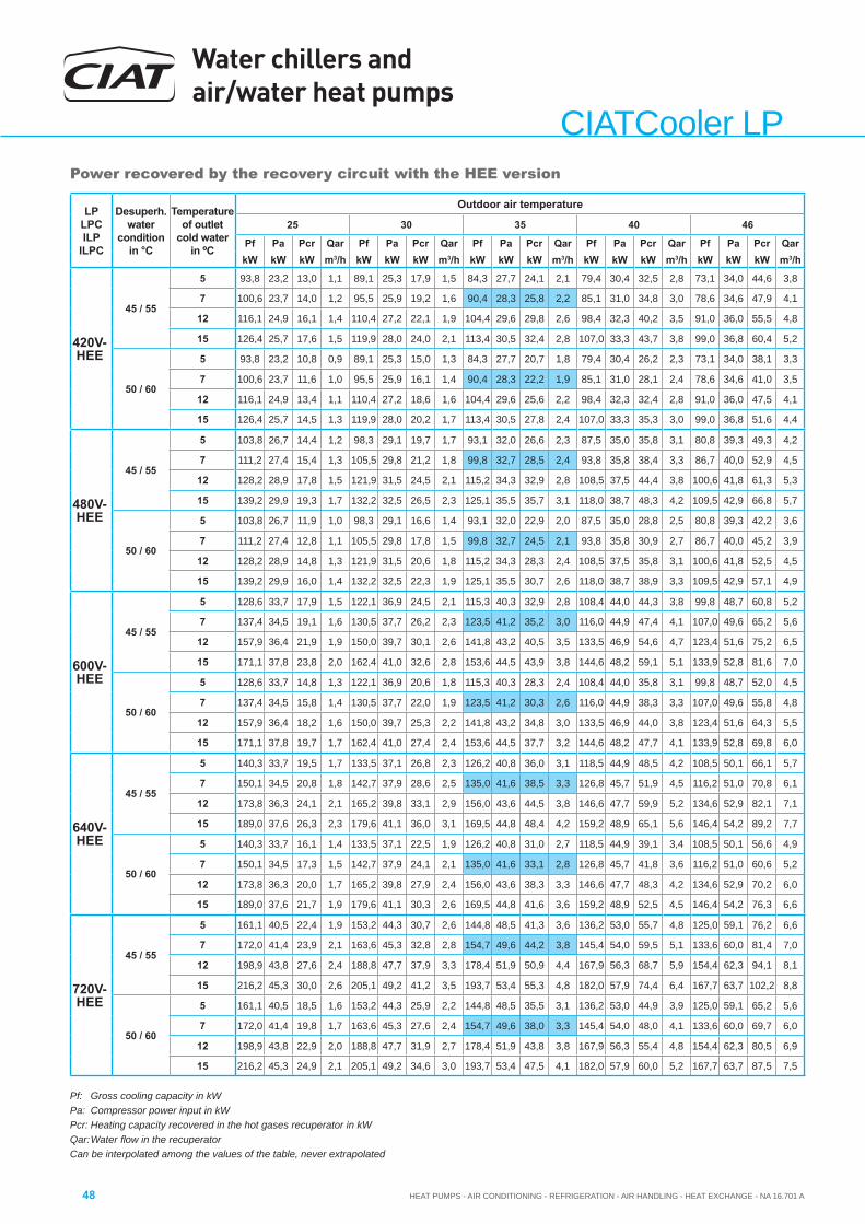
Water chillers and air/water heat pumps
HEAT PUMPS - AIR CONDITIONING - REFRIGERATION - AIR HANDLING - HEAT EXCHANGE - NA 16.701 A48
CIATCooler LPPower recovered by the recovery circuit with the HEE version
LP LPCILP
ILPC
Desuperh.water
conditionin °C
Temperature of outlet
cold water in ºC
Outdoor air temperature
25 30 35 40 46
Pf Pa Pcr Qar Pf Pa Pcr Qar Pf Pa Pcr Qar Pf Pa Pcr Qar Pf Pa Pcr QarkW kW kW m3/h kW kW kW m3/h kW kW kW m3/h kW kW kW m3/h kW kW kW m3/h
420V-HEE
45 / 55
5 93,8 23,2 13,0 1,1 89,1 25,3 17,9 1,5 84,3 27,7 24,1 2,1 79,4 30,4 32,5 2,8 73,1 34,0 44,6 3,8
7 100,6 23,7 14,0 1,2 95,5 25,9 19,2 1,6 90,4 28,3 25,8 2,2 85,1 31,0 34,8 3,0 78,6 34,6 47,9 4,1
12 116,1 24,9 16,1 1,4 110,4 27,2 22,1 1,9 104,4 29,6 29,8 2,6 98,4 32,3 40,2 3,5 91,0 36,0 55,5 4,8
15 126,4 25,7 17,6 1,5 119,9 28,0 24,0 2,1 113,4 30,5 32,4 2,8 107,0 33,3 43,7 3,8 99,0 36,8 60,4 5,2
50 / 60
5 93,8 23,2 10,8 0,9 89,1 25,3 15,0 1,3 84,3 27,7 20,7 1,8 79,4 30,4 26,2 2,3 73,1 34,0 38,1 3,3
7 100,6 23,7 11,6 1,0 95,5 25,9 16,1 1,4 90,4 28,3 22,2 1,9 85,1 31,0 28,1 2,4 78,6 34,6 41,0 3,5
12 116,1 24,9 13,4 1,1 110,4 27,2 18,6 1,6 104,4 29,6 25,6 2,2 98,4 32,3 32,4 2,8 91,0 36,0 47,5 4,1
15 126,4 25,7 14,5 1,3 119,9 28,0 20,2 1,7 113,4 30,5 27,8 2,4 107,0 33,3 35,3 3,0 99,0 36,8 51,6 4,4
480V-HEE
45 / 55
5 103,8 26,7 14,4 1,2 98,3 29,1 19,7 1,7 93,1 32,0 26,6 2,3 87,5 35,0 35,8 3,1 80,8 39,3 49,3 4,2
7 111,2 27,4 15,4 1,3 105,5 29,8 21,2 1,8 99,8 32,7 28,5 2,4 93,8 35,8 38,4 3,3 86,7 40,0 52,9 4,5
12 128,2 28,9 17,8 1,5 121,9 31,5 24,5 2,1 115,2 34,3 32,9 2,8 108,5 37,5 44,4 3,8 100,6 41,8 61,3 5,3
15 139,2 29,9 19,3 1,7 132,2 32,5 26,5 2,3 125,1 35,5 35,7 3,1 118,0 38,7 48,3 4,2 109,5 42,9 66,8 5,7
50 / 60
5 103,8 26,7 11,9 1,0 98,3 29,1 16,6 1,4 93,1 32,0 22,9 2,0 87,5 35,0 28,8 2,5 80,8 39,3 42,2 3,6
7 111,2 27,4 12,8 1,1 105,5 29,8 17,8 1,5 99,8 32,7 24,5 2,1 93,8 35,8 30,9 2,7 86,7 40,0 45,2 3,9
12 128,2 28,9 14,8 1,3 121,9 31,5 20,6 1,8 115,2 34,3 28,3 2,4 108,5 37,5 35,8 3,1 100,6 41,8 52,5 4,5
15 139,2 29,9 16,0 1,4 132,2 32,5 22,3 1,9 125,1 35,5 30,7 2,6 118,0 38,7 38,9 3,3 109,5 42,9 57,1 4,9
600V-HEE
45 / 55
5 128,6 33,7 17,9 1,5 122,1 36,9 24,5 2,1 115,3 40,3 32,9 2,8 108,4 44,0 44,3 3,8 99,8 48,7 60,8 5,2
7 137,4 34,5 19,1 1,6 130,5 37,7 26,2 2,3 123,5 41,2 35,2 3,0 116,0 44,9 47,4 4,1 107,0 49,6 65,2 5,6
12 157,9 36,4 21,9 1,9 150,0 39,7 30,1 2,6 141,8 43,2 40,5 3,5 133,5 46,9 54,6 4,7 123,4 51,6 75,2 6,5
15 171,1 37,8 23,8 2,0 162,4 41,0 32,6 2,8 153,6 44,5 43,9 3,8 144,6 48,2 59,1 5,1 133,9 52,8 81,6 7,0
50 / 60
5 128,6 33,7 14,8 1,3 122,1 36,9 20,6 1,8 115,3 40,3 28,3 2,4 108,4 44,0 35,8 3,1 99,8 48,7 52,0 4,5
7 137,4 34,5 15,8 1,4 130,5 37,7 22,0 1,9 123,5 41,2 30,3 2,6 116,0 44,9 38,3 3,3 107,0 49,6 55,8 4,8
12 157,9 36,4 18,2 1,6 150,0 39,7 25,3 2,2 141,8 43,2 34,8 3,0 133,5 46,9 44,0 3,8 123,4 51,6 64,3 5,5
15 171,1 37,8 19,7 1,7 162,4 41,0 27,4 2,4 153,6 44,5 37,7 3,2 144,6 48,2 47,7 4,1 133,9 52,8 69,8 6,0
640V-HEE
45 / 55
5 140,3 33,7 19,5 1,7 133,5 37,1 26,8 2,3 126,2 40,8 36,0 3,1 118,5 44,9 48,5 4,2 108,5 50,1 66,1 5,7
7 150,1 34,5 20,8 1,8 142,7 37,9 28,6 2,5 135,0 41,6 38,5 3,3 126,8 45,7 51,9 4,5 116,2 51,0 70,8 6,1
12 173,8 36,3 24,1 2,1 165,2 39,8 33,1 2,9 156,0 43,6 44,5 3,8 146,6 47,7 59,9 5,2 134,6 52,9 82,1 7,1
15 189,0 37,6 26,3 2,3 179,6 41,1 36,0 3,1 169,5 44,8 48,4 4,2 159,2 48,9 65,1 5,6 146,4 54,2 89,2 7,7
50 / 60
5 140,3 33,7 16,1 1,4 133,5 37,1 22,5 1,9 126,2 40,8 31,0 2,7 118,5 44,9 39,1 3,4 108,5 50,1 56,6 4,9
7 150,1 34,5 17,3 1,5 142,7 37,9 24,1 2,1 135,0 41,6 33,1 2,8 126,8 45,7 41,8 3,6 116,2 51,0 60,6 5,2
12 173,8 36,3 20,0 1,7 165,2 39,8 27,9 2,4 156,0 43,6 38,3 3,3 146,6 47,7 48,3 4,2 134,6 52,9 70,2 6,0
15 189,0 37,6 21,7 1,9 179,6 41,1 30,3 2,6 169,5 44,8 41,6 3,6 159,2 48,9 52,5 4,5 146,4 54,2 76,3 6,6
720V-HEE
45 / 55
5 161,1 40,5 22,4 1,9 153,2 44,3 30,7 2,6 144,8 48,5 41,3 3,6 136,2 53,0 55,7 4,8 125,0 59,1 76,2 6,6
7 172,0 41,4 23,9 2,1 163,6 45,3 32,8 2,8 154,7 49,6 44,2 3,8 145,4 54,0 59,5 5,1 133,6 60,0 81,4 7,0
12 198,9 43,8 27,6 2,4 188,8 47,7 37,9 3,3 178,4 51,9 50,9 4,4 167,9 56,3 68,7 5,9 154,4 62,3 94,1 8,1
15 216,2 45,3 30,0 2,6 205,1 49,2 41,2 3,5 193,7 53,4 55,3 4,8 182,0 57,9 74,4 6,4 167,7 63,7 102,2 8,8
50 / 60
5 161,1 40,5 18,5 1,6 153,2 44,3 25,9 2,2 144,8 48,5 35,5 3,1 136,2 53,0 44,9 3,9 125,0 59,1 65,2 5,6
7 172,0 41,4 19,8 1,7 163,6 45,3 27,6 2,4 154,7 49,6 38,0 3,3 145,4 54,0 48,0 4,1 133,6 60,0 69,7 6,0
12 198,9 43,8 22,9 2,0 188,8 47,7 31,9 2,7 178,4 51,9 43,8 3,8 167,9 56,3 55,4 4,8 154,4 62,3 80,5 6,9
15 216,2 45,3 24,9 2,1 205,1 49,2 34,6 3,0 193,7 53,4 47,5 4,1 182,0 57,9 60,0 5,2 167,7 63,7 87,5 7,5
Pf: Gross cooling capacity in kWPa: Compressor power input in kWPcr: Heating capacity recovered in the hot gases recuperator in kWQar: Water fl ow in the recuperatorCan be interpolated among the values of the table, never extrapolated
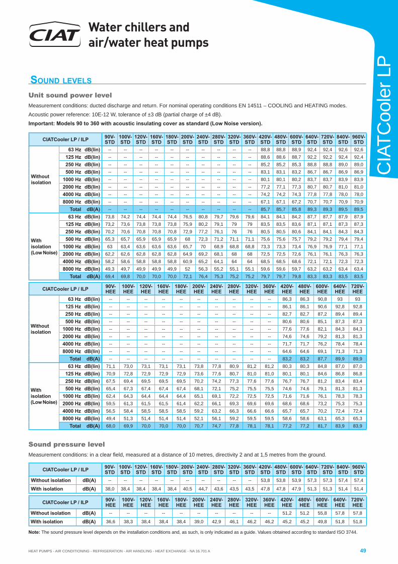
HEAT PUMPS - AIR CONDITIONING - REFRIGERATION - AIR HANDLING - HEAT EXCHANGE - NA 16.701 A
Water chillers and air/water heat pumps
49
CIA
TCoo
ler L
P
CIATCooler LP / ILP 90V-STD
100V-STD
120V-STD
160V-STD
180V-STD
200V-STD
240V-STD
280V-STD
320V-STD
360V-STD
420V-STD
480V-STD
600V-STD
640V-STD
720V-STD
840V-STD
960V-STD
Withoutisolation
63 Hz dB(lin) -- -- -- -- -- -- -- -- -- -- 88,8 88,8 88,9 92,4 92,4 92,6 92,6125 Hz dB(lin) -- -- -- -- -- -- -- -- -- -- 88,6 88,6 88,7 92,2 92,2 92,4 92,4250 Hz dB(lin) -- -- -- -- -- -- -- -- -- -- 85,2 85,2 85,3 88,8 88,8 89,0 89,0500 Hz dB(lin) -- -- -- -- -- -- -- -- -- -- 83,1 83,1 83,2 86,7 86,7 86,9 86,9
1000 Hz dB(lin) -- -- -- -- -- -- -- -- -- -- 80,1 80,1 80,2 83,7 83,7 83,9 83,92000 Hz dB(lin) -- -- -- -- -- -- -- -- -- -- 77,2 77,1 77,3 80,7 80,7 81,0 81,04000 Hz dB(lin) -- -- -- -- -- -- -- -- -- -- 74,2 74,2 74,3 77,8 77,8 78,0 78,08000 Hz dB(lin) -- -- -- -- -- -- -- -- -- -- 67,1 67,1 67,2 70,7 70,7 70,9 70,9
Total dB(A) -- -- -- -- -- -- -- -- -- -- 85,7 85,7 85,8 89,3 89,3 89,5 89,5
Withisolation (Low Noise)
63 Hz dB(lin) 73,8 74,2 74,4 74,4 74,4 76,5 80,8 79,7 79,6 79,6 84,1 84,1 84,2 87,7 87,7 87,9 87,9125 Hz dB(lin) 73,2 73,6 73,8 73,8 73,8 75,9 80,2 79,1 79 79 83,5 83,5 83,6 87,1 87,1 87,3 87,3250 Hz dB(lin) 70,2 70,6 70,8 70,8 70,8 72,9 77,2 76,1 76 76 80,5 80,5 80,6 84,1 84,1 84,3 84,3500 Hz dB(lin) 65,3 65,7 65,9 65,9 65,9 68 72,3 71,2 71,1 71,1 75,6 75,6 75,7 79,2 79,2 79,4 79,4
1000 Hz dB(lin) 63 63,4 63,6 63,6 63,6 65,7 70 68,9 68,8 68,8 73,3 73,3 73,4 76,9 76,9 77,1 77,12000 Hz dB(lin) 62,2 62,6 62,8 62,8 62,8 64,9 69,2 68,1 68 68 72,5 72,5 72,6 76,1 76,1 76,3 76,34000 Hz dB(lin) 58,2 58,6 58,8 58,8 58,8 60,9 65,2 64,1 64 64 68,5 68,5 68,6 72,1 72,1 72,3 72,38000 Hz dB(lin) 49,3 49,7 49,9 49,9 49,9 52 56,3 55,2 55,1 55,1 59,6 59,6 59,7 63,2 63,2 63,4 63,4
Total dB(A) 69,4 69,8 70,0 70,0 70,0 72,1 76,4 75,3 75,2 75,2 79,7 79,7 79,8 83,3 83,3 83,5 83,5
CIATCooler LP / ILP 90V-STD
100V-STD
120V-STD
160V-STD
180V-STD
200V-STD
240V-STD
280V-STD
320V-STD
360V-STD
420V-STD
480V-STD
600V-STD
640V-STD
720V-STD
840V-STD
960V-STD
Without isolation dB(A) -- -- -- -- -- -- -- -- -- -- 53,8 53,8 53,9 57,3 57,3 57,4 57,4
With isolation dB(A) 38,0 38,4 38,4 38,4 38,4 40,5 44,7 43,6 43,5 43,5 47,8 47,8 47,9 51,3 51,3 51,4 51,4
CIATCooler LP / ILP 90V-HEE
100V-HEE
120V-HEE
160V-HEE
180V-HEE
200V-HEE
240V-HEE
280V-HEE
320V-HEE
360V-HEE
420V-HEE
480V-HEE
600V-HEE
640V-HEE
720V-HEE
Withoutisolation
63 Hz dB(lin) -- -- -- -- -- -- -- -- -- -- 86,3 86,3 90,8 93 93125 Hz dB(lin) -- -- -- -- -- -- -- -- -- -- 86,1 86,1 90,6 92,8 92,8250 Hz dB(lin) -- -- -- -- -- -- -- -- -- -- 82,7 82,7 87,2 89,4 89,4500 Hz dB(lin) -- -- -- -- -- -- -- -- -- -- 80,6 80,6 85,1 87,3 87,3
1000 Hz dB(lin) -- -- -- -- -- -- -- -- -- -- 77,6 77,6 82,1 84,3 84,32000 Hz dB(lin) -- -- -- -- -- -- -- -- -- -- 74,6 74,6 79,2 81,3 81,34000 Hz dB(lin) -- -- -- -- -- -- -- -- -- -- 71,7 71,7 76,2 78,4 78,48000 Hz dB(lin) -- -- -- -- -- -- -- -- -- -- 64,6 64,6 69,1 71,3 71,3
Total dB(A) -- -- -- -- -- -- -- -- -- -- 83,2 83,2 87,7 89,9 89,9
Withisolation (Low Noise)
63 Hz dB(lin) 71,1 73,0 73,1 73,1 73,1 73,8 77,8 80,9 81,2 81,2 80,3 80,3 84,8 87,0 87,0125 Hz dB(lin) 70,9 72,8 72,9 72,9 72,9 73,6 77,6 80,7 81,0 81,0 80,1 80,1 84,6 86,8 86,8250 Hz dB(lin) 67,5 69,4 69,5 69,5 69,5 70,2 74,2 77,3 77,6 77,6 76,7 76,7 81,2 83,4 83,4500 Hz dB(lin) 65,4 67,3 67,4 67,4 67,4 68,1 72,1 75,2 75,5 75,5 74,6 74,6 79,1 81,3 81,3
1000 Hz dB(lin) 62,4 64,3 64,4 64,4 64,4 65,1 69,1 72,2 72,5 72,5 71,6 71,6 76,1 78,3 78,32000 Hz dB(lin) 59,5 61,3 61,5 61,5 61,4 62,2 66,1 69,3 69,6 69,6 68,6 68,6 73,2 75,3 75,34000 Hz dB(lin) 56,5 58,4 58,5 58,5 58,5 59,2 63,2 66,3 66,6 66,6 65,7 65,7 70,2 72,4 72,48000 Hz dB(lin) 49,4 51,3 51,4 51,4 51,4 52,1 56,1 59,2 59,5 59,5 58,6 58,6 63,1 65,3 65,3
Total dB(A) 68,0 69,9 70,0 70,0 70,0 70,7 74,7 77,8 78,1 78,1 77,2 77,2 81,7 83,9 83,9
CIATCooler LP / ILP 90V-HEE
100V-HEE
120V-HEE
160V-HEE
180V-HEE
200V-HEE
240V-HEE
280V-HEE
320V-HEE
360V-HEE
420V-HEE
480V-HEE
600V-HEE
640V-HEE
720V-HEE
Without isolation dB(A) -- -- -- -- -- -- -- -- -- -- 51,2 51,2 55,8 57,8 57,8
With isolation dB(A) 36,6 38,3 38,4 38,4 38,4 39,0 42,9 46,1 46,2 46,2 45,2 45,2 49,8 51,8 51,8
SOUND LEVELS
Unit sound power levelMeasurement conditions: ducted discharge and return. For nominal operating conditions EN 14511 – COOLING and HEATING modes.
Acoustic power reference: 10E-12 W, tolerance of ±3 dB (partial charge of ±4 dB).
Important: Models 90 to 360 with acoustic insulating cover as standard (Low Noise version).
Sound pressure levelMeasurement conditions: in a clear fi eld, measured at a distance of 10 metres, directivity 2 and at 1,5 metres from the ground.
Note: The sound pressure level depends on the installation conditions and, as such, is only indicated as a guide. Values obtained according to standard ISO 3744.
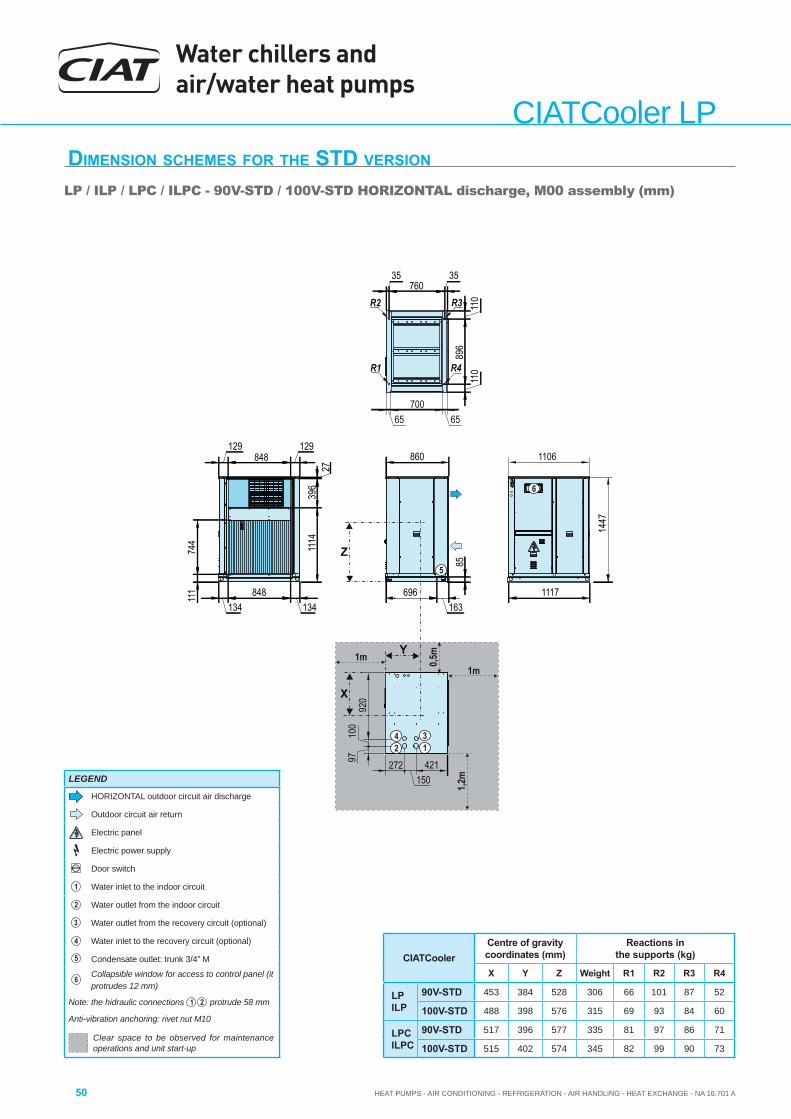
Water chillers and air/water heat pumps
HEAT PUMPS - AIR CONDITIONING - REFRIGERATION - AIR HANDLING - HEAT EXCHANGE - NA 16.701 A50
CIATCooler LPDIMENSION SCHEMES FOR THE STD VERSION
LP / ILP / LPC / ILPC - 90V-STD / 100V-STD HORIZONTAL discharge, M00 assembly (mm)
CIATCoolerCentre of gravity coordinates (mm)
Reactions in the supports (kg)
X Y Z Weight R1 R2 R3 R4
LPILP
90V-STD 453 384 528 306 66 101 87 52
100V-STD 488 398 576 315 69 93 84 60
LPCILPC
90V-STD 517 396 577 335 81 97 86 71
100V-STD 515 402 574 345 82 99 90 73
X
Y
111
744
134848
134
896
110
110
696163
85
1447
1117
35760
35
129848
129860
1114
396
27
Z5
R1
R3
R4
421150
272
920
100
97
42 1
3
1106
65700
65
R2
1m
1,2m
1m 0,5m
6
LEGEND
HORIZONTAL outdoor circuit air discharge
Outdoor circuit air return
Electric panel
Electric power supply
Door switch
1 Water inlet to the indoor circuit
2 Water outlet from the indoor circuit
3 Water outlet from the recovery circuit (optional)
4 Water inlet to the recovery circuit (optional)
5 Condensate outlet: trunk 3/4” M
6 Collapsible window for access to control panel (it protrudes 12 mm)
Note: the hidraulic connections 1 2 protrude 58 mm
Anti-vibration anchoring: rivet nut M10
Clear space to be observed for maintenance operations and unit start-up

HEAT PUMPS - AIR CONDITIONING - REFRIGERATION - AIR HANDLING - HEAT EXCHANGE - NA 16.701 A
Water chillers and air/water heat pumps
51
CIA
TCoo
ler L
P
DIMENSION SCHEMES FOR THE STD VERSION LP / ILP / LPC / ILPC - 90V-STD / 100V-STD VERTICAL discharge, M01 assembly (mm)
X
Y
111
744
134848
134
896
110
110
696163
85
1447
1117
35760
35
860
Z5
R1
R3
R4
421150
272
920
100
97
42 1
3
1106
65700
65
R2
172 415 256
410
482
214
1474
1m
1,2m
1m
0,5m
6
CIATCoolerCentre of gravity coordinates (mm)
Reactions in the supports (kg)
X Y Z Weight R1 R2 R3 R4
LPILP
90V-STD 453 384 528 306 66 101 87 52
100V-STD 488 398 576 315 69 93 84 60
LPCILPC
90V-STD 517 396 577 335 81 97 86 71
100V-STD 515 402 574 345 82 99 90 73
LEGEND
VERTICAL outdoor circuit air discharge
Outdoor circuit air return
Electric panel
Electric power supply
Door switch
1 Water inlet to the indoor circuit
2 Water outlet from the indoor circuit
3 Water outlet from the recovery circuit (optional)
4 Water inlet to the recovery circuit (optional)
5 Condensate outlet: trunk 3/4” M
6 Collapsible window for access to control panel (it protrudes 12 mm)
Note: the hidraulic connections 1 2 protrude 58 mm
Anti-vibration anchoring: rivet nut M10
Clear space to be observed for maintenance operations and unit start-up
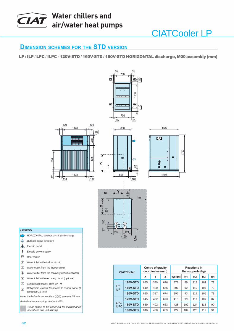
Water chillers and air/water heat pumps
HEAT PUMPS - AIR CONDITIONING - REFRIGERATION - AIR HANDLING - HEAT EXCHANGE - NA 16.701 A52
CIATCooler LPDIMENSION SCHEMES FOR THE STD VERSION LP / ILP / LPC / ILPC - 120V-STD / 160V-STD / 180V-STD HORIZONTAL discharge, M00 assembly (mm)
CIATCoolerCentre of gravity coordinates (mm)
Reactions in the supports (kg)
X Y Z Weight R1 R2 R3 R4
LPILP
120V-STD 625 399 676 379 89 112 101 77
160V-STD 619 400 666 397 92 119 107 79
180V-STD 625 397 674 396 93 119 105 79
LPCILPC
120V-STD 645 402 673 410 99 117 107 87
160V-STD 639 402 663 428 102 124 113 90
180V-STD 646 400 669 429 104 123 111 91
X
Y
1727
85
1230
470
27
1291128
129
894
111
1341128
134696
1631398
860
Z5
1201
100
97
1387
1166
110
110
35760
35
421150
272
42 1
3
1m
1,5m
1m
0,5m
R1
R3
R4
R2
65700
65
6
LEGEND
HORIZONTAL outdoor circuit air discharge
Outdoor circuit air return
Electric panel
Electric power supply
Door switch
1 Water inlet to the indoor circuit
2 Water outlet from the indoor circuit
3 Water outlet from the recovery circuit (optional)
4 Water inlet to the recovery circuit (optional)
5 Condensate outlet: trunk 3/4” M
6 Collapsible window for access to control panel (it protrudes 12 mm)
Note: the hidraulic connections 1 2 protrude 58 mm
Anti-vibration anchoring: rivet nut M10
Clear space to be observed for maintenance operations and unit start-up
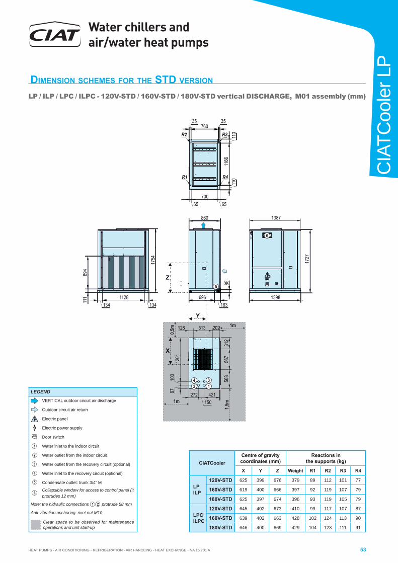
HEAT PUMPS - AIR CONDITIONING - REFRIGERATION - AIR HANDLING - HEAT EXCHANGE - NA 16.701 A
Water chillers and air/water heat pumps
53
CIA
TCoo
ler L
P
DIMENSION SCHEMES FOR THE STD VERSION
LP / ILP / LPC / ILPC - 120V-STD / 160V-STD / 180V-STD vertical DISCHARGE, M01 assembly (mm)
X
Y17
27
85
894
111
1341128
134696
1631398
860
Z5
1201
100
97
138711
6611
011
0
35760
35
421150
272
42 1
3 508
567
312
202513128
1754
1m
1,5m1m
0,5m
R1
R3
R4
R2
65700
65
6
CIATCoolerCentre of gravity coordinates (mm)
Reactions in the supports (kg)
X Y Z Weight R1 R2 R3 R4
LPILP
120V-STD 625 399 676 379 89 112 101 77
160V-STD 619 400 666 397 92 119 107 79
180V-STD 625 397 674 396 93 119 105 79
LPCILPC
120V-STD 645 402 673 410 99 117 107 87
160V-STD 639 402 663 428 102 124 113 90
180V-STD 646 400 669 429 104 123 111 91
LEGEND
VERTICAL outdoor circuit air discharge
Outdoor circuit air return
Electric panel
Electric power supply
Door switch
1 Water inlet to the indoor circuit
2 Water outlet from the indoor circuit
3 Water outlet from the recovery circuit (optional)
4 Water inlet to the recovery circuit (optional)
5 Condensate outlet: trunk 3/4” M
6 Collapsible window for access to control panel (it protrudes 12 mm)
Note: the hidraulic connections 1 2 protrude 58 mm
Anti-vibration anchoring: rivet nut M10
Clear space to be observed for maintenance operations and unit start-up
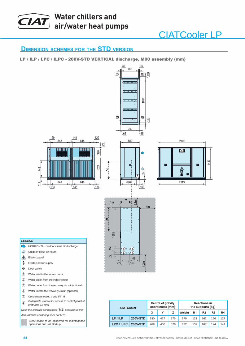
Water chillers and air/water heat pumps
HEAT PUMPS - AIR CONDITIONING - REFRIGERATION - AIR HANDLING - HEAT EXCHANGE - NA 16.701 A54
CIATCooler LPDIMENSION SCHEMES FOR THE STD VERSION
LP / ILP / LPC / ILPC - 200V-STD VERTICAL discharge, M00 assembly (mm)
CIATCoolerCentre of gravity coordinates (mm)
Reactions in the supports (kg)
X Y Z Weight R1 R2 R3 R4
LP / ILP 200V-STD 930 427 575 579 121 162 166 127
LPC / ILPC 200V-STD 969 430 576 622 137 167 174 144
110
1892
110
696163
85
2113
1447
860
1024
396
27
129848
148848
129
111
744
134848
148848
134
Z
X
Y
5
1m
1,2m
1m 0,5m
2102
421150272
1885
150
77
42 1
3
35760
35
65700
65
R1
R3
R4
R2
6
LEGEND
HORIZONTAL outdoor circuit air discharge
Outdoor circuit air return
Electric panel
Electric power supply
Door switch
1 Water inlet to the indoor circuit
2 Water outlet from the indoor circuit
3 Water outlet from the recovery circuit (optional)
4 Water inlet to the recovery circuit (optional)
5 Condensate outlet: trunk 3/4” M
6 Collapsible window for access to control panel (it protrudes 12 mm)
Note: the hidraulic connections 1 2 protrude 58 mm
Anti-vibration anchoring: rivet nut M10
Clear space to be observed for maintenance operations and unit start-up

HEAT PUMPS - AIR CONDITIONING - REFRIGERATION - AIR HANDLING - HEAT EXCHANGE - NA 16.701 A
Water chillers and air/water heat pumps
55
CIA
TCoo
ler L
P
DIMENSION SCHEMES FOR THE STD VERSION
LP / ILP / LPC / ILPC - 200V-STD HORIZONTAL discharge, M01 assembly (mm)
1m
1,2m1m
0,5m
110
1892
110
696163
85
2113
1447
860
111
744
134848
148848
134
X
Y
5
410
482
514
482
214
257415171
Z
2102
421150
272
1885
150
77
42 1
3
35760
35
65700
65
1474
R1
R3
R4
R2
6
CIATCoolerCentre of gravity coordinates (mm)
Reactions in the supports (kg)
X Y Z Weight R1 R2 R3 R4
LP / ILP 200V-STD 930 427 575 579 121 162 166 127
LPC / ILPC 200V-STD 969 430 576 622 137 167 174 144
LEGEND
VERTICAL outdoor circuit air discharge
Outdoor circuit air return
Electric panel
Electric power supply
Door switch
1 Water inlet to the indoor circuit
2 Water outlet from the indoor circuit
3 Water outlet from the recovery circuit (optional)
4 Water inlet to the recovery circuit (optional)
5 Condensate outlet: trunk 3/4” M
6 Collapsible window for access to control panel (it protrudes 12 mm)
Note: the hidraulic connections 1 2 protrude 58 mm
Anti-vibration anchoring: rivet nut M10
Clear space to be observed for maintenance operations and unit start-up
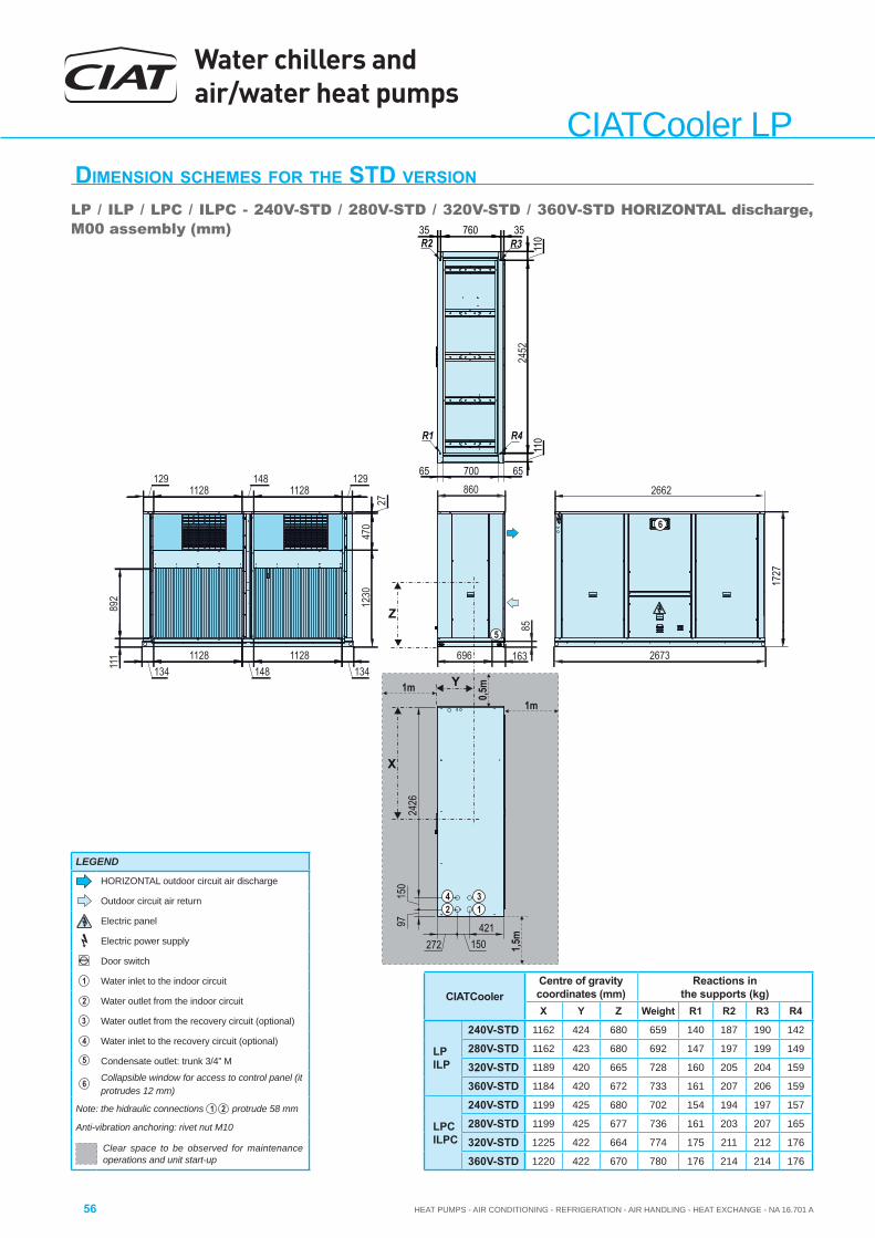
Water chillers and air/water heat pumps
HEAT PUMPS - AIR CONDITIONING - REFRIGERATION - AIR HANDLING - HEAT EXCHANGE - NA 16.701 A56
CIATCooler LPDIMENSION SCHEMES FOR THE STD VERSION
LP / ILP / LPC / ILPC - 240V-STD / 280V-STD / 320V-STD / 360V-STD HORIZONTAL discharge, M00 assembly (mm)
X
Y
696 163
8524
52
2673
860 2662
111
892
1341128
1481128
134
1230
470
27
1291128
1481128
129
5
Z
1727
110
35 760 35R3R2
110R1 R4
6570065
1m
1,5m
1m
0,5m
2426
150
97
42 1
3
421150272
6
CIATCoolerCentre of gravity coordinates (mm)
Reactions in the supports (kg)
X Y Z Weight R1 R2 R3 R4
LPILP
240V-STD 1162 424 680 659 140 187 190 142
280V-STD 1162 423 680 692 147 197 199 149
320V-STD 1189 420 665 728 160 205 204 159
360V-STD 1184 420 672 733 161 207 206 159
LPCILPC
240V-STD 1199 425 680 702 154 194 197 157
280V-STD 1199 425 677 736 161 203 207 165
320V-STD 1225 422 664 774 175 211 212 176
360V-STD 1220 422 670 780 176 214 214 176
LEGEND
HORIZONTAL outdoor circuit air discharge
Outdoor circuit air return
Electric panel
Electric power supply
Door switch
1 Water inlet to the indoor circuit
2 Water outlet from the indoor circuit
3 Water outlet from the recovery circuit (optional)
4 Water inlet to the recovery circuit (optional)
5 Condensate outlet: trunk 3/4” M
6 Collapsible window for access to control panel (it protrudes 12 mm)
Note: the hidraulic connections 1 2 protrude 58 mm
Anti-vibration anchoring: rivet nut M10
Clear space to be observed for maintenance operations and unit start-up
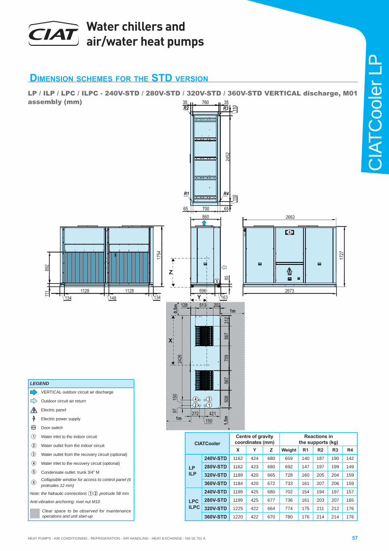
HEAT PUMPS - AIR CONDITIONING - REFRIGERATION - AIR HANDLING - HEAT EXCHANGE - NA 16.701 A
Water chillers and air/water heat pumps
57
CIA
TCoo
ler L
P
DIMENSION SCHEMES FOR THE STD VERSION
LP / ILP / LPC / ILPC - 240V-STD / 280V-STD / 320V-STD / 360V-STD VERTICAL discharge, M01 assembly (mm)
X
Y
1m
696
8524
52
2673
860 2662
111
892
1341128
1481128
134
5
Z
1,5m1m
1727
11035 760 35
R3R2
110R1 R4
6570065
1754
567
312
202513128
709
567
508
0,5m
163
2426
150
97
42 1
3
421150
272
6
CIATCoolerCentre of gravity coordinates (mm)
Reactions in the supports (kg)
X Y Z Weight R1 R2 R3 R4
LPILP
240V-STD 1162 424 680 659 140 187 190 142
280V-STD 1162 423 680 692 147 197 199 149
320V-STD 1189 420 665 728 160 205 204 159
360V-STD 1184 420 672 733 161 207 206 159
LPCILPC
240V-STD 1199 425 680 702 154 194 197 157
280V-STD 1199 425 677 736 161 203 207 165
320V-STD 1225 422 664 774 175 211 212 176
360V-STD 1220 422 670 780 176 214 214 176
LEGEND
VERTICAL outdoor circuit air discharge
Outdoor circuit air return
Electric panel
Electric power supply
Door switch
1 Water inlet to the indoor circuit
2 Water outlet from the indoor circuit
3 Water outlet from the recovery circuit (optional)
4 Water inlet to the recovery circuit (optional)
5 Condensate outlet: trunk 3/4” M
6 Collapsible window for access to control panel (it protrudes 12 mm)
Note: the hidraulic connections 1 2 protrude 58 mm
Anti-vibration anchoring: rivet nut M10
Clear space to be observed for maintenance operations and unit start-up
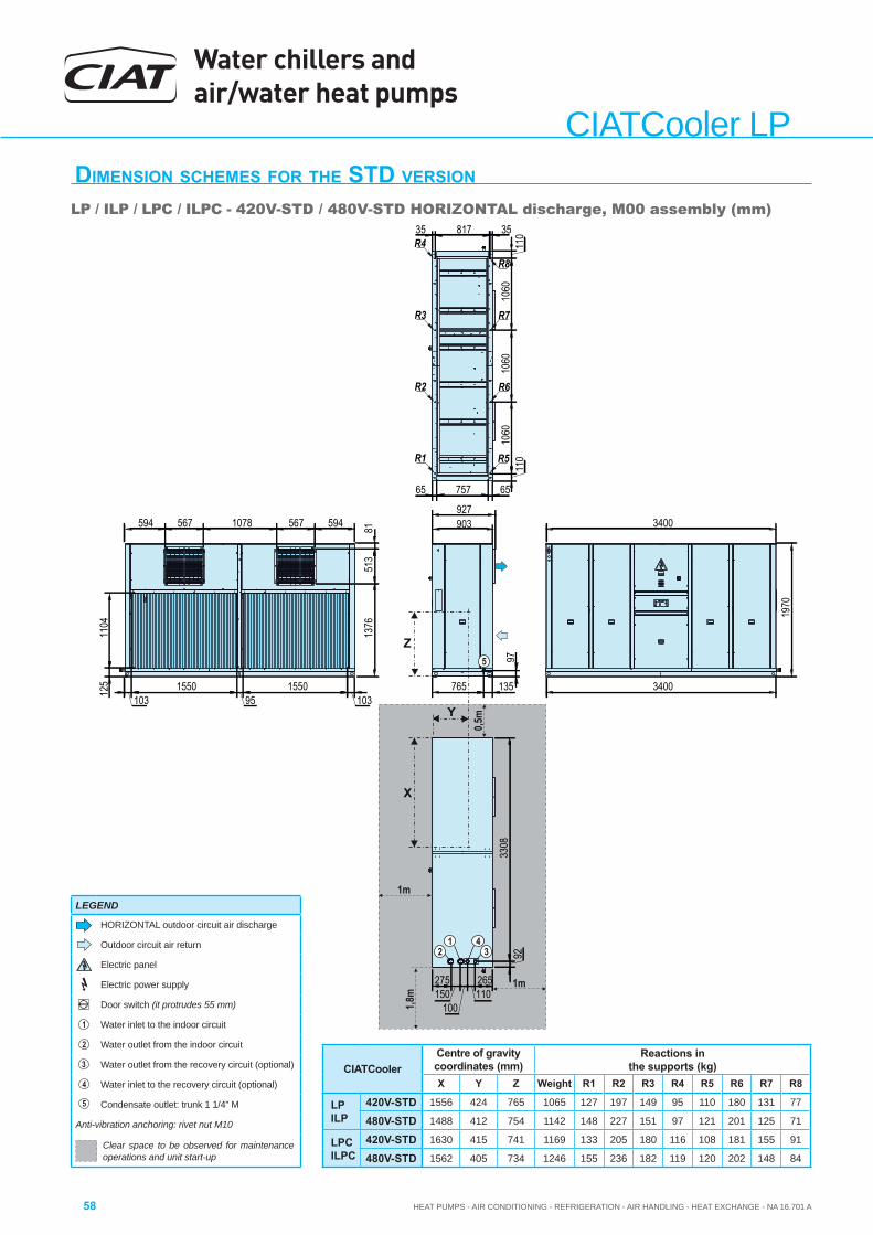
Water chillers and air/water heat pumps
HEAT PUMPS - AIR CONDITIONING - REFRIGERATION - AIR HANDLING - HEAT EXCHANGE - NA 16.701 A58
CIATCooler LPDIMENSION SCHEMES FOR THE STD VERSION
LP / ILP / LPC / ILPC - 420V-STD / 480V-STD HORIZONTAL discharge, M00 assembly (mm)
R5
R6
R7
R8
R1
R2
R3
R4
Y
1m
1m
0,5m
Z
1,8m
X
110
1060
1060
1060
1103581735
6575765
3400
1970
3400
765 135
97
275150
100110265
3308
92
1376
513
81
1031550
951550
103
1104
594 567 1078 567 594 903927
125
5
42
13
CIATCoolerCentre of gravity coordinates (mm)
Reactions in the supports (kg)
X Y Z Weight R1 R2 R3 R4 R5 R6 R7 R8
LPILP
420V-STD 1556 424 765 1065 127 197 149 95 110 180 131 77
480V-STD 1488 412 754 1142 148 227 151 97 121 201 125 71
LPCILPC
420V-STD 1630 415 741 1169 133 205 180 116 108 181 155 91
480V-STD 1562 405 734 1246 155 236 182 119 120 202 148 84
LEGEND
HORIZONTAL outdoor circuit air discharge
Outdoor circuit air return
Electric panel
Electric power supply
Door switch (it protrudes 55 mm)
1 Water inlet to the indoor circuit
2 Water outlet from the indoor circuit
3 Water outlet from the recovery circuit (optional)
4 Water inlet to the recovery circuit (optional)
5 Condensate outlet: trunk 1 1/4” M
Anti-vibration anchoring: rivet nut M10
Clear space to be observed for maintenance operations and unit start-up
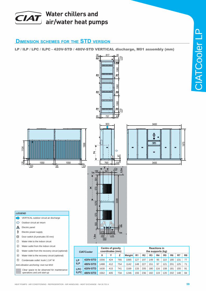
HEAT PUMPS - AIR CONDITIONING - REFRIGERATION - AIR HANDLING - HEAT EXCHANGE - NA 16.701 A
Water chillers and air/water heat pumps
59
CIA
TCoo
ler L
P
DIMENSION SCHEMES FOR THE STD VERSION
LP / ILP / LPC / ILPC - 420V-STD / 480V-STD VERTICAL discharge, M01 assembly (mm)
Y
1m
1m 0,5m
Z
1,8m
X
110
1060
1060
1060
1103581735
6575765
3400
1970
3400
765 135
97
275150
100110265
3308
92
1998
1031550
951550
103
1104
125
593
570
1076
570
591
186 541174
903
R5
R6
R7
R8
R1
R2
R3
R4
5
42
13
CIATCoolerCentre of gravity coordinates (mm)
Reactions in the supports (kg)
X Y Z Weight R1 R2 R3 R4 R5 R6 R7 R8
LPILP
420V-STD 1556 424 765 1065 127 197 149 95 110 180 131 77
480V-STD 1488 412 754 1142 148 227 151 97 121 201 125 71
LPCILPC
420V-STD 1630 415 741 1169 133 205 180 116 108 181 155 91
480V-STD 1562 405 734 1246 155 236 182 119 120 202 148 84
LEGEND
VERTICAL outdoor circuit air discharge
Outdoor circuit air return
Electric panel
Electric power supply
Door switch (it protrudes 55 mm)
1 Water inlet to the indoor circuit
2 Water outlet from the indoor circuit
3 Water outlet from the recovery circuit (optional)
4 Water inlet to the recovery circuit (optional)
5 Condensate outlet: trunk 1 1/4” M
Anti-vibration anchoring: rivet nut M10
Clear space to be observed for maintenance operations and unit start-up
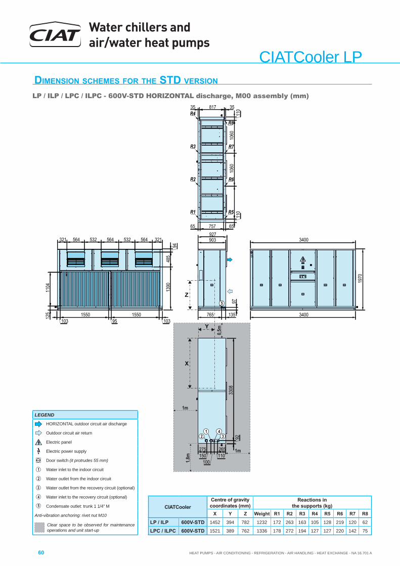
Water chillers and air/water heat pumps
HEAT PUMPS - AIR CONDITIONING - REFRIGERATION - AIR HANDLING - HEAT EXCHANGE - NA 16.701 A60
CIATCooler LPDIMENSION SCHEMES FOR THE STD VERSION
LP / ILP / LPC / ILPC - 600V-STD HORIZONTAL discharge, M00 assembly (mm)
Y
1m
1m
0,5m
Z
1,8m
X
R5
R6
R7
R8
R1
R2
R3
R4
110
1060
1060
1103581735
6575765
3400
1970
3400
765 135
97
275150
100110265
3308
92
1031550
951550
103
1104
927
125
1390
485
94
321564532564532564321 903
5
42
13
CIATCoolerCentre of gravity coordinates (mm)
Reactions in the supports (kg)
X Y Z Weight R1 R2 R3 R4 R5 R6 R7 R8
LP / ILP 600V-STD 1452 394 782 1232 172 263 163 105 128 219 120 62
LPC / ILPC 600V-STD 1521 389 762 1336 178 272 194 127 127 220 142 75
LEGEND
HORIZONTAL outdoor circuit air discharge
Outdoor circuit air return
Electric panel
Electric power supply
Door switch (it protrudes 55 mm)
1 Water inlet to the indoor circuit
2 Water outlet from the indoor circuit
3 Water outlet from the recovery circuit (optional)
4 Water inlet to the recovery circuit (optional)
5 Condensate outlet: trunk 1 1/4” M
Anti-vibration anchoring: rivet nut M10
Clear space to be observed for maintenance operations and unit start-up
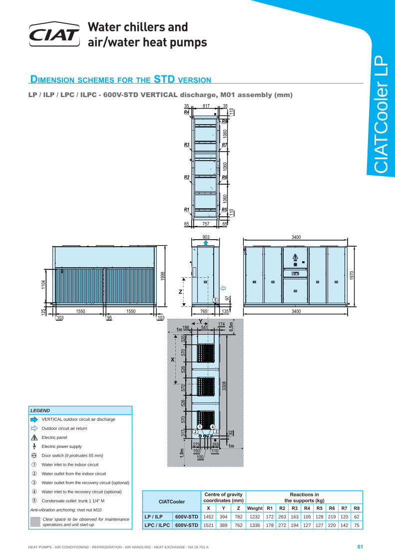
HEAT PUMPS - AIR CONDITIONING - REFRIGERATION - AIR HANDLING - HEAT EXCHANGE - NA 16.701 A
Water chillers and air/water heat pumps
61
CIA
TCoo
ler L
P
DIMENSION SCHEMES FOR THE STD VERSION
LP / ILP / LPC / ILPC - 600V-STD VERTICAL discharge, M01 assembly (mm)
Y
1m
1m 0,5m
Z
1,8m
X
R5
R6
R7
R8
R1
R2
R3
R4
110
1060
1060
1060
1103581735
6575765
3400
1970
3400
765 135
97
275150
100110265
3308
92
1031550
951550
103
1104
125
1998
317
570
526
570
526
570
320
186 541 174
5
42
13
903
CIATCoolerCentre of gravity coordinates (mm)
Reactions in the supports (kg)
X Y Z Weight R1 R2 R3 R4 R5 R6 R7 R8
LP / ILP 600V-STD 1452 394 782 1232 172 263 163 105 128 219 120 62
LPC / ILPC 600V-STD 1521 389 762 1336 178 272 194 127 127 220 142 75
LEGEND
VERTICAL outdoor circuit air discharge
Outdoor circuit air return
Electric panel
Electric power supply
Door switch (it protrudes 55 mm)
1 Water inlet to the indoor circuit
2 Water outlet from the indoor circuit
3 Water outlet from the recovery circuit (optional)
4 Water inlet to the recovery circuit (optional)
5 Condensate outlet: trunk 1 1/4” M
Anti-vibration anchoring: rivet nut M10
Clear space to be observed for maintenance operations and unit start-up
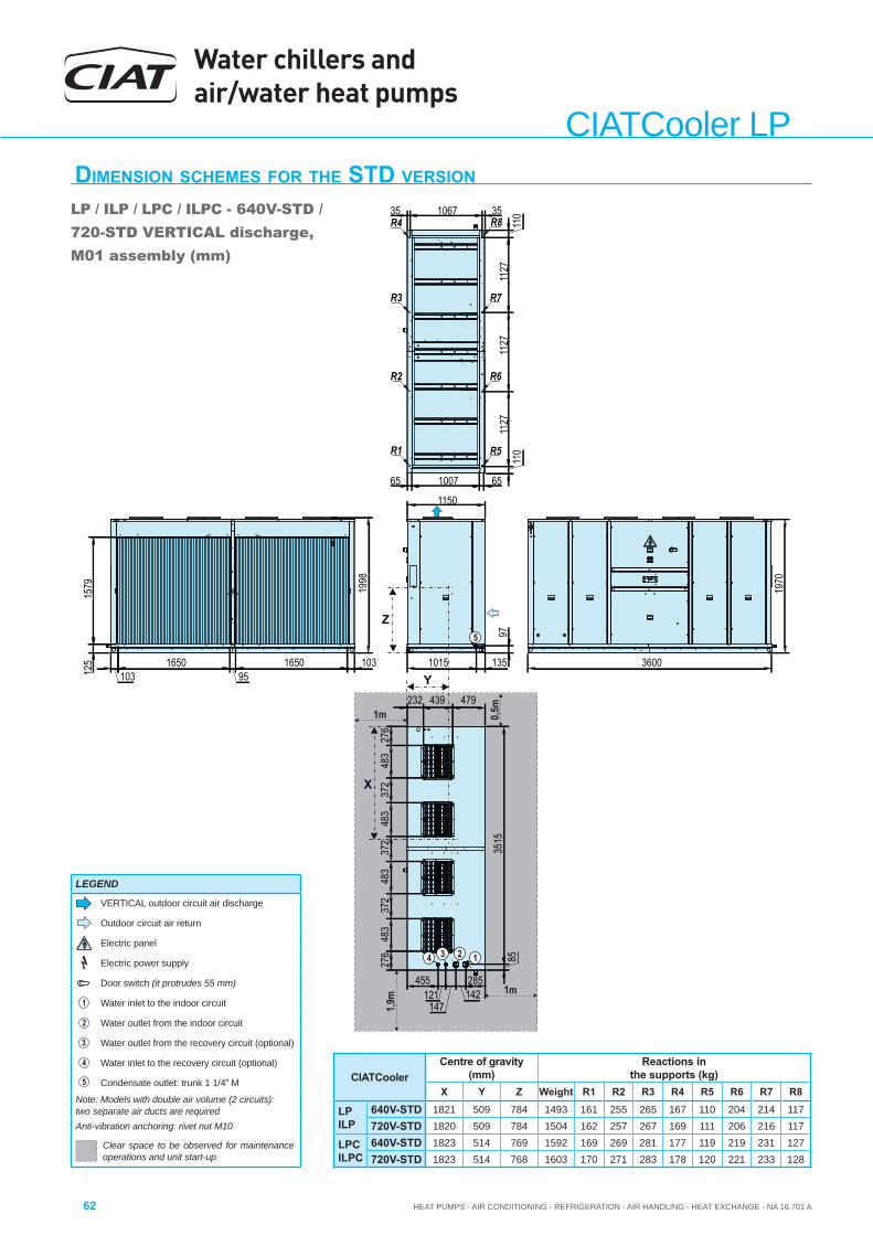
Water chillers and air/water heat pumps
HEAT PUMPS - AIR CONDITIONING - REFRIGERATION - AIR HANDLING - HEAT EXCHANGE - NA 16.701 A62
CIATCooler LPDIMENSION SCHEMES FOR THE STD VERSION
LP / ILP / LPC / ILPC - 640V-STD / 720-STD VERTICAL discharge, M01 assembly (mm)
Y
1m
1m 0,5m
Z
1,9m
X
R5
R6
R7
R8
R1
R2
R3
R4
1970
3600
1998
455121
147142285
1015 135
9735
1585276
483
372
483
372
483
372
483
276
479439232
103165095
1650103
1579
110
1127
1127
1127
110
65100765
35106735
125
1150
5
4 2 13
CIATCoolerCentre of gravity
(mm)Reactions in
the supports (kg)X Y Z Weight R1 R2 R3 R4 R5 R6 R7 R8
LPILP
640V-STD 1821 509 784 1493 161 255 265 167 110 204 214 117720V-STD 1820 509 784 1504 162 257 267 169 111 206 216 117
LPCILPC
640V-STD 1823 514 769 1592 169 269 281 177 119 219 231 127720V-STD 1823 514 768 1603 170 271 283 178 120 221 233 128
LEGEND
VERTICAL outdoor circuit air discharge
Outdoor circuit air return
Electric panel
Electric power supply
Door switch (it protrudes 55 mm)
1 Water inlet to the indoor circuit
2 Water outlet from the indoor circuit
3 Water outlet from the recovery circuit (optional)
4 Water inlet to the recovery circuit (optional)
5 Condensate outlet: trunk 1 1/4” M
Note: Models with double air volume (2 circuits): two separate air ducts are requiredAnti-vibration anchoring: rivet nut M10
Clear space to be observed for maintenance operations and unit start-up

HEAT PUMPS - AIR CONDITIONING - REFRIGERATION - AIR HANDLING - HEAT EXCHANGE - NA 16.701 A
Water chillers and air/water heat pumps
63
CIA
TCoo
ler L
P
Y
1m
1m 0,5m
Z
2,4m
X
R5
R6
R7
R8
R1
R2
R3
R4
R9
R10
R11
R12
370
567
498
567
498
567
498
567
370
430121
147192
310
35 1117 35
4375
125
110
856
856
856
856
856
110
65105765
4500
1970
1065
135
97
1999
1654
103210095
210010312
5
506513182
1200
5
4 2 13
CIATCoolerCentre gravity
(mm)Reactions in
the supports (kg)X Y Z Weight R1 R2 R3 R4 R5 R6 R7 R8 R9 R10 R11 R12
LPILP
840V-STD 2271 544 772 1986 148 167 175 180 182 170 140 157 165 170 172 162960V-STD 2272 548 762 2138 158 178 187 192 194 182 152 170 179 184 186 176
LPCILPC
840V-STD 2287 558 754 2131 152 172 182 189 192 181 151 171 181 188 192 181960V-STD 2285 544 746 2282 167 190 200 207 211 198 159 178 189 196 199 189
DIMENSION SCHEMES FOR THE STD VERSION
LP / ILP / LPC / ILPC - 840V-STD / 960-STD VERTICAL discharge, M01 assembly (mm)
LEGEND
VERTICAL outdoor circuit air discharge
Outdoor circuit air return
Electric panel
Electric power supply
Door switch (it protrudes 55 mm)
1 Water inlet to the indoor circuit
2 Water outlet from the indoor circuit
3 Water outlet from the recovery circuit (optional)
4 Water inlet to the recovery circuit (optional)
5 Condensate outlet: trunk 1 1/4” M
Note: Models with double air volume (2 circuits): two separate air ducts are required Anti-vibration anchoring: rivet nut M10
Clear space to be observed for maintenance operations and unit start-up
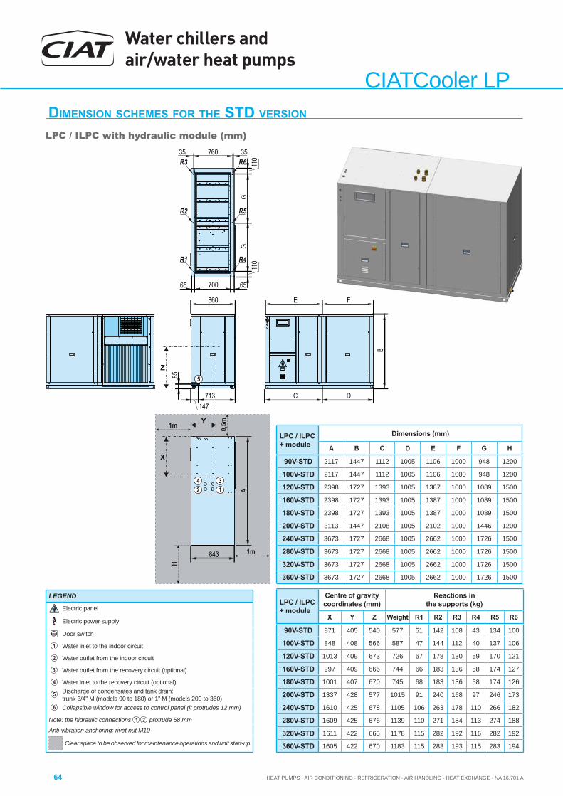
Water chillers and air/water heat pumps
HEAT PUMPS - AIR CONDITIONING - REFRIGERATION - AIR HANDLING - HEAT EXCHANGE - NA 16.701 A64
CIATCooler LPDIMENSION SCHEMES FOR THE STD VERSION
LPC / ILPC with hydraulic module (mm)
X
Y
Z
H
C D
E F
110
6570065
GG
110
35 760 35
B
A
860
843
147713
85
R1 R4
R2 R5
R3 R6
5
42 1
3
1m
1m 0,5m
LPC / ILPC + module
Centre of gravity coordinates (mm)
Reactions in the supports (kg)
X Y Z Weight R1 R2 R3 R4 R5 R6
90V-STD 871 405 540 577 51 142 108 43 134 100
100V-STD 848 408 566 587 47 144 112 40 137 106
120V-STD 1013 409 673 726 67 178 130 59 170 121
160V-STD 997 409 666 744 66 183 136 58 174 127
180V-STD 1001 407 670 745 68 183 136 58 174 126
200V-STD 1337 428 577 1015 91 240 168 97 246 173
240V-STD 1610 425 678 1105 106 263 178 110 266 182
280V-STD 1609 425 676 1139 110 271 184 113 274 188
320V-STD 1611 422 665 1178 115 282 192 116 282 192
360V-STD 1605 422 670 1183 115 283 193 115 283 194
LEGEND
Electric panel
Electric power supply
Door switch
1 Water inlet to the indoor circuit
2 Water outlet from the indoor circuit
3 Water outlet from the recovery circuit (optional)
4 Water inlet to the recovery circuit (optional)
5Discharge of condensates and tank drain: trunk 3/4” M (models 90 to 180) or 1” M (models 200 to 360)
6 Collapsible window for access to control panel (it protrudes 12 mm)
Note: the hidraulic connections 1 2 protrude 58 mm
Anti-vibration anchoring: rivet nut M10
Clear space to be observed for maintenance operations and unit start-up
LPC / ILPC + module
Dimensions (mm)
A B C D E F G H
90V-STD 2117 1447 1112 1005 1106 1000 948 1200
100V-STD 2117 1447 1112 1005 1106 1000 948 1200
120V-STD 2398 1727 1393 1005 1387 1000 1089 1500
160V-STD 2398 1727 1393 1005 1387 1000 1089 1500
180V-STD 2398 1727 1393 1005 1387 1000 1089 1500
200V-STD 3113 1447 2108 1005 2102 1000 1446 1200
240V-STD 3673 1727 2668 1005 2662 1000 1726 1500
280V-STD 3673 1727 2668 1005 2662 1000 1726 1500
320V-STD 3673 1727 2668 1005 2662 1000 1726 1500
360V-STD 3673 1727 2668 1005 2662 1000 1726 1500
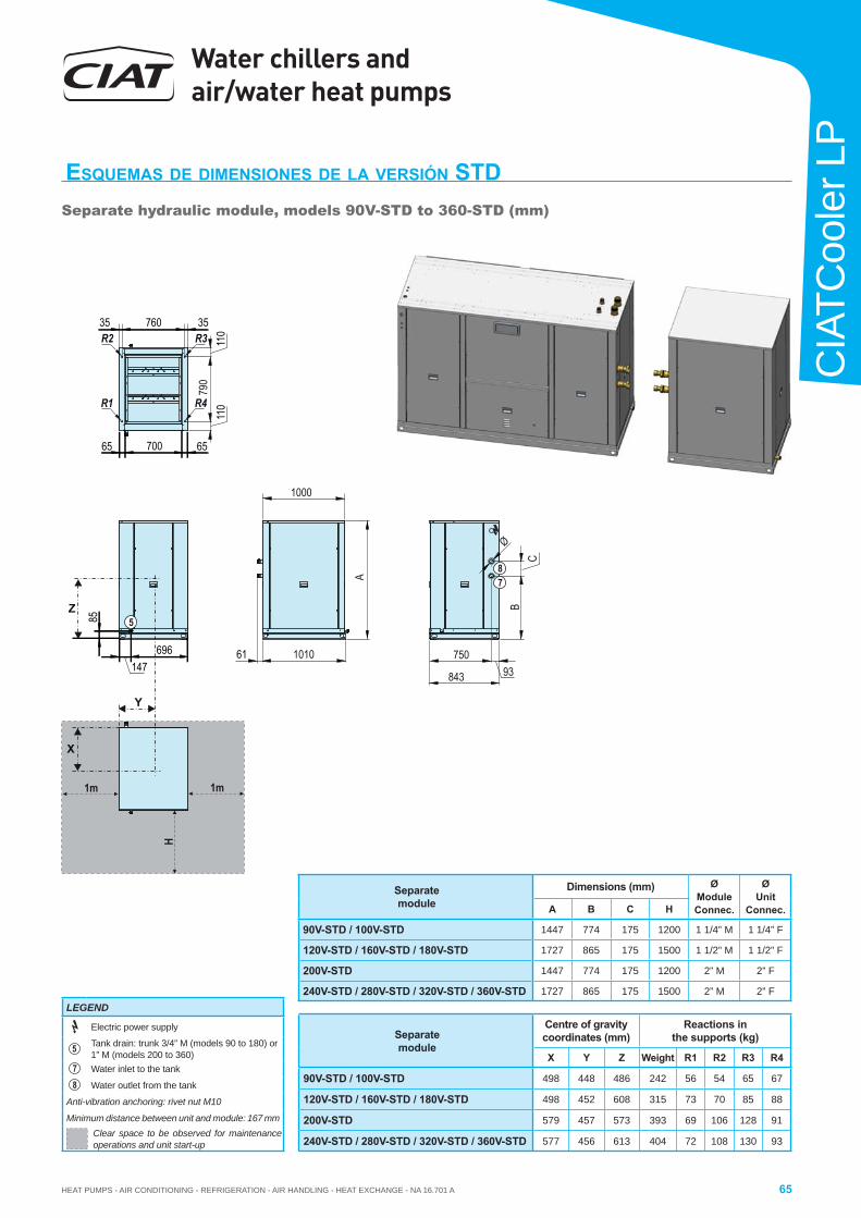
HEAT PUMPS - AIR CONDITIONING - REFRIGERATION - AIR HANDLING - HEAT EXCHANGE - NA 16.701 A
Water chillers and air/water heat pumps
65
CIA
TCoo
ler L
P1m
H
1m
BC
93750
790
1010
843
1000
A
35 760 35
110
110
6570065
5
78
R1 R4
R2 R3
X
Y
Z
Ø
61147
696
85
ESQUEMAS DE DIMENSIONES DE LA VERSIÓN STDSeparate hydraulic module, models 90V-STD to 360-STD (mm)
Separatemodule
Centre of gravity coordinates (mm)
Reactions in the supports (kg)
X Y Z Weight R1 R2 R3 R4
90V-STD / 100V-STD 498 448 486 242 56 54 65 67
120V-STD / 160V-STD / 180V-STD 498 452 608 315 73 70 85 88
200V-STD 579 457 573 393 69 106 128 91
240V-STD / 280V-STD / 320V-STD / 360V-STD 577 456 613 404 72 108 130 93
Separatemodule
Dimensions (mm) Ø ModuleConnec.
Ø Unit
Connec.A B C H
90V-STD / 100V-STD 1447 774 175 1200 1 1/4” M 1 1/4” F
120V-STD / 160V-STD / 180V-STD 1727 865 175 1500 1 1/2” M 1 1/2” F
200V-STD 1447 774 175 1200 2” M 2” F
240V-STD / 280V-STD / 320V-STD / 360V-STD 1727 865 175 1500 2” M 2” FLEGEND
Electric power supply
5Tank drain: trunk 3/4” M (models 90 to 180) or 1” M (models 200 to 360)
7 Water inlet to the tank
8 Water outlet from the tank
Anti-vibration anchoring: rivet nut M10
Minimum distance between unit and module: 167 mmClear space to be observed for maintenance operations and unit start-up
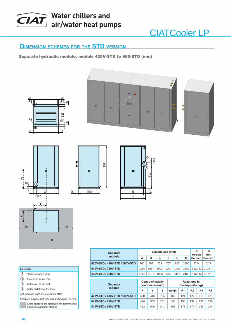
Water chillers and air/water heat pumps
HEAT PUMPS - AIR CONDITIONING - REFRIGERATION - AIR HANDLING - HEAT EXCHANGE - NA 16.701 A66
CIATCooler LPDIMENSION SCHEMES FOR THE STD VERSION
Separate hydraulic module, models 420V-STD to 960-STD (mm)
1m
H
1m
C
1970
98 B 93
1042
175
1000147
Z
85 5
X
Y
Ø
78
A
65 D 65
8882
588
35 E 35
R1 R4
R2 R3
Separatemodule
Centre of gravity coordinates (mm)
Reactions in the supports (kg)
X Y Z Weight R1 R2 R3 R4
420V-STD / 480V-STD / 600V-STD 498 445 784 486 124 122 119 121
640V-STD / 720V-STD 494 583 781 544 136 132 136 140
840V-STD / 960V-STD 492 600 841 668 175 170 159 164
LEGEND
Electric power supply
5 Tank drain: trunk 1” M
7 Water inlet to the tank
8 Water outlet from the tank
Anti-vibration anchoring: rivet nut M10
Minimum distance between unit and module: 167 mm
Clear space to be observed for maintenance operations and unit start-up
Separatemodule
Dimensions (mm) Ø ModuleConnec.
Ø Unit
Connec.A B C D E H
420V-STD / 480V-STD / 600V-STD 900 807 753 757 817 1800 2” M 2” F
640V-STD / 720V-STD 1150 1057 1003 1007 1067 1900 2 1/2” M 2 1/2” F
840V-STD / 960V-STD 1200 1107 1053 1057 1117 2400 2 1/2” M 2 1/2” F
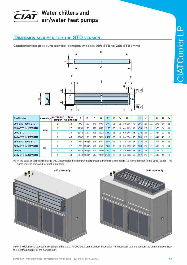
HEAT PUMPS - AIR CONDITIONING - REFRIGERATION - AIR HANDLING - HEAT EXCHANGE - NA 16.701 A
Water chillers and air/water heat pumps
67
CIA
TCoo
ler L
P
DIMENSION SCHEMES FOR THE STD VERSION
Condensation pressure control damper, models 90V-STD to 360-STD (mm)
CIATCooler Assembly Servos perdamper
Totalweight (kg) A B C D E F G H I J K L M N O
90V-STD / 100V-STD
M00
1 13 978 150 446 895 845 25 11 3 x 266 49 396 25 11 296 64 11
120V-STD to 180V-STD 1 17 1258 150 520 1175 1125 25 11 4 x 269 49 470 25 11 370 64 11
200V-STD 1 34 1970 150 428 1892 1842 25 11 5 x 348 75 378 25 11 327 39 11
240V-STD to 360V-STD 1 43 2582 150 550 2452 2402 25 11 6 x 384 75 500 25 11 447 41 10
90V-STD / 100V-STD
M01
1 13 633 150 (*) 428 550 500 25 11 1 x 400 75 378 25 11 278 64 11
120V-STD to 180V-STD 1 17 733 150 (*) 550 650 600 25 11 2 x 250 75 500 25 11 400 64 11
200V-STD 1 34 1642 150 (*) 549 1550 1500 25 11 4 x 350 75 497 25 11 447 41 10
240V-STD to 360V-STD 1 43 2243 150 (*) 547 2150 2100 25 11 6 x 333 75 497 25 11 447 41 10
M00 assembly M01 assembly
Note: By default this damper is sent attached to the CIATCooler LP unit. For duct installation it is necessary to unscrew from the unit and disconnect the electrical supply of the servomotor.
(*) In the case of vertical discharge (M01 assembly), the damper incorporates a frame (60 mm height) to fi t the damper to the fan(s) outlet. This frame may be removed for duct installation.
FE
F
C
D
BA
I H I
G
NOM
NO
KJ
K
L
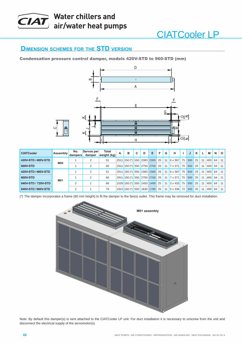
Water chillers and air/water heat pumps
HEAT PUMPS - AIR CONDITIONING - REFRIGERATION - AIR HANDLING - HEAT EXCHANGE - NA 16.701 A68
CIATCooler LPDIMENSION SCHEMES FOR THE STD VERSION
Condensation pressure control damper, models 420V-STD to 960-STD (mm)
CIATCooler Assembly No. dampers
Servos perdamper
Totalweight (kg) A B C D E F G H I J K L M N O
420V-STD / 480V-STDM00
1 2 51 2511 150 (*) 550 2383 2300 25 11 6 x 367 75 500 25 11 400 64 11
600V-STD 1 2 60 2911 150 (*) 550 2750 2700 25 11 7 x 371 75 500 25 11 400 64 11
420V-STD / 480V-STD
M01
1 2 51 2511 150 (*) 550 2383 2300 25 11 6 x 367 75 500 25 11 400 64 11
600V-STD 1 2 60 2911 150 (*) 550 2750 2700 25 11 7 x 371 75 500 25 11 400 64 11
640V-STD / 720V-STD 2 1 66 1535 150 (*) 550 1450 1400 25 11 3 x 433 75 500 25 11 400 64 11
840V-STD / 960V-STD 2 1 79 1915 150 (*) 550 1830 1780 25 11 5 x 336 72 500 25 11 400 64 11
Note: By default this damper(s) is sent attached to the CIATCooler LP unit. For duct installation it is necessary to unscrew from the unit and disconnect the electrical supply of the servomotor(s).
(*) The damper incorporates a frame (60 mm height) to fi t the damper to the fan(s) outlet. This frame may be removed for duct installation.
FE
F
C
D
BA
I H I
G
NOM
NO
KJ
K
L
M01 assembly
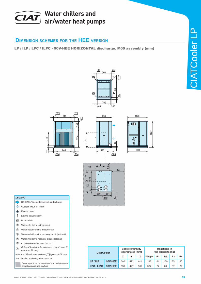
HEAT PUMPS - AIR CONDITIONING - REFRIGERATION - AIR HANDLING - HEAT EXCHANGE - NA 16.701 A
Water chillers and air/water heat pumps
69
CIA
TCoo
ler L
P
DIMENSION SCHEMES FOR THE HEE VERSION
LP / ILP / LPC / ILPC - 90V-HEE HORIZONTAL discharge, M00 assembly (mm)
CIATCoolerCentre of gravity coordinates (mm)
Reactions in the supports (kg)
X Y Z Weight R1 R2 R3 R4
LP / ILP 90V-HEE 502 422 614 298 64 100 85 50
LPC / ILPC 90V-HEE 538 427 599 327 77 84 87 79
X
Y
111
744
134848
134
896
110
110
696163
85
1447
1117
35760
35
129848
129860
1114
396
27
Z5
R1
R3
R4
421150
272
920
100
97
42 1
3
1106
65700
65
R2
1m
1,2m
1m 0,5m
6
LEGEND
HORIZONTAL outdoor circuit air discharge
Outdoor circuit air return
Electric panel
Electric power supply
Door switch
1 Water inlet to the indoor circuit
2 Water outlet from the indoor circuit
3 Water outlet from the recovery circuit (optional)
4 Water inlet to the recovery circuit (optional)
5 Condensate outlet: trunk 3/4” M
6 Collapsible window for access to control panel (it protrudes 12 mm)
Note: the hidraulic connections 1 2 protrude 58 mm
Anti-vibration anchoring: rivet nut M10
Clear space to be observed for maintenance operations and unit start-up
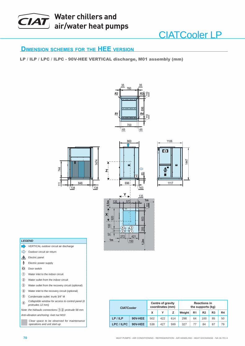
Water chillers and air/water heat pumps
HEAT PUMPS - AIR CONDITIONING - REFRIGERATION - AIR HANDLING - HEAT EXCHANGE - NA 16.701 A70
CIATCooler LPDIMENSION SCHEMES FOR THE HEE VERSION LP / ILP / LPC / ILPC - 90V-HEE VERTICAL discharge, M01 assembly (mm)
CIATCoolerCentre of gravity coordinates (mm)
Reactions in the supports (kg)
X Y Z Weight R1 R2 R3 R4
LP / ILP 90V-HEE 502 422 614 298 64 100 85 50
LPC / ILPC 90V-HEE 538 427 599 327 77 84 87 79
X
Y
111
744
134848
134
896
110
110
696163
85
1447
1117
35760
35
860
Z5
R1
R3
R4
421150
272
920
100
97
42 1
3
1106
65700
65
R2
135 573135
355
603
153
1474
1m
1,2m
1m
0,5m
6
LEGEND
VERTICAL outdoor circuit air discharge
Outdoor circuit air return
Electric panel
Electric power supply
Door switch
1 Water inlet to the indoor circuit
2 Water outlet from the indoor circuit
3 Water outlet from the recovery circuit (optional)
4 Water inlet to the recovery circuit (optional)
5 Condensate outlet: trunk 3/4” M
6 Collapsible window for access to control panel (it protrudes 12 mm)
Note: the hidraulic connections 1 2 protrude 58 mm
Anti-vibration anchoring: rivet nut M10
Clear space to be observed for maintenance operations and unit start-up
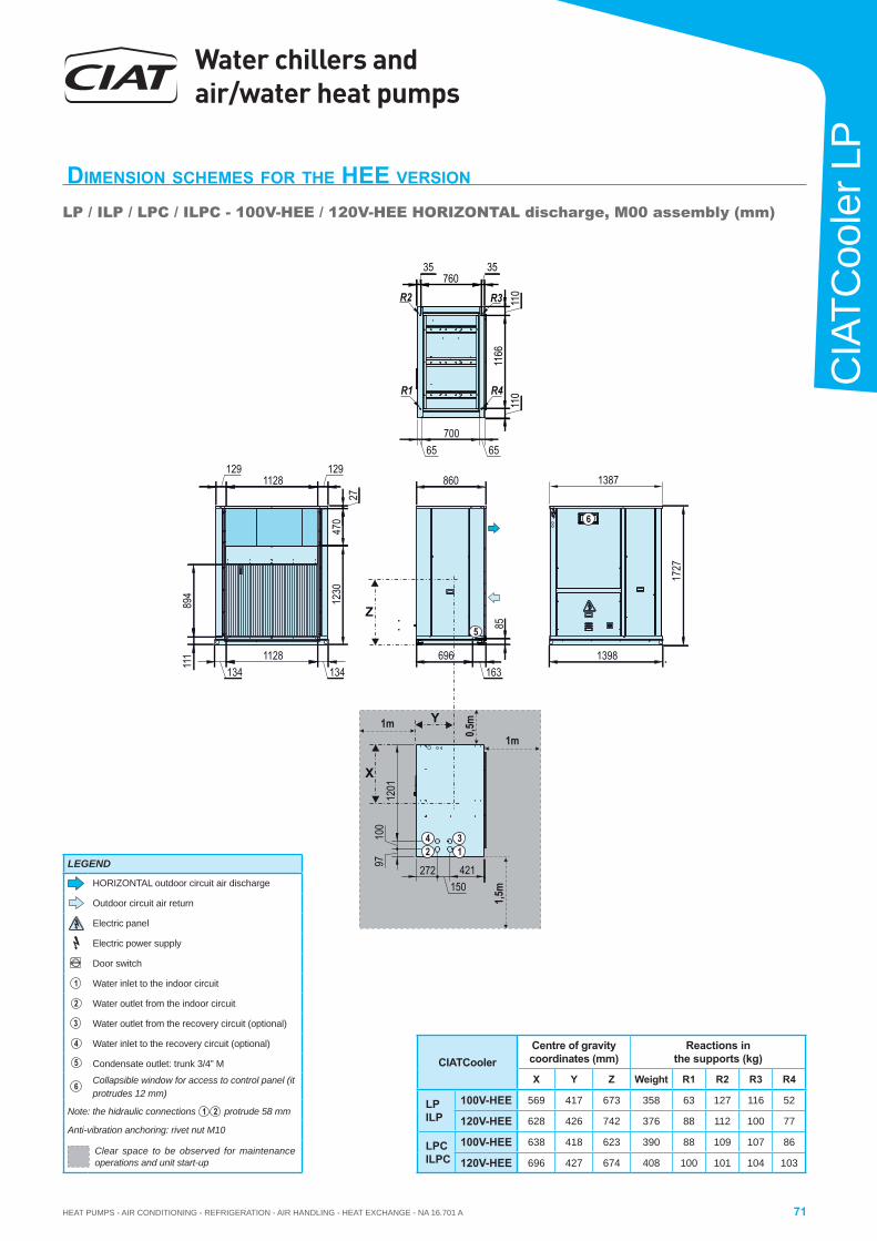
HEAT PUMPS - AIR CONDITIONING - REFRIGERATION - AIR HANDLING - HEAT EXCHANGE - NA 16.701 A
Water chillers and air/water heat pumps
71
CIA
TCoo
ler L
P
DIMENSION SCHEMES FOR THE HEE VERSION
LP / ILP / LPC / ILPC - 100V-HEE / 120V-HEE HORIZONTAL discharge, M00 assembly (mm)
CIATCoolerCentre of gravity coordinates (mm)
Reactions in the supports (kg)
X Y Z Weight R1 R2 R3 R4
LPILP
100V-HEE 569 417 673 358 63 127 116 52
120V-HEE 628 426 742 376 88 112 100 77
LPCILPC
100V-HEE 638 418 623 390 88 109 107 86
120V-HEE 696 427 674 408 100 101 104 103
X
Y
1727
85
1230
470
27
1291128
129
894
111
1341128
134696
1631398
860
Z5
1201
100
97
138711
6611
011
0
35760
35
421150
272
42 1
3
1m
1,5m
1m
0,5m
R1
R3
R4
R2
65700
65
6
LEGEND
HORIZONTAL outdoor circuit air discharge
Outdoor circuit air return
Electric panel
Electric power supply
Door switch
1 Water inlet to the indoor circuit
2 Water outlet from the indoor circuit
3 Water outlet from the recovery circuit (optional)
4 Water inlet to the recovery circuit (optional)
5 Condensate outlet: trunk 3/4” M
6 Collapsible window for access to control panel (it protrudes 12 mm)
Note: the hidraulic connections 1 2 protrude 58 mm
Anti-vibration anchoring: rivet nut M10
Clear space to be observed for maintenance operations and unit start-up
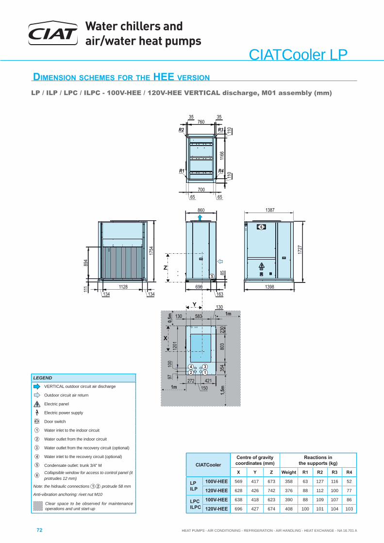
Water chillers and air/water heat pumps
HEAT PUMPS - AIR CONDITIONING - REFRIGERATION - AIR HANDLING - HEAT EXCHANGE - NA 16.701 A72
CIATCooler LPDIMENSION SCHEMES FOR THE HEE VERSION
LP / ILP / LPC / ILPC - 100V-HEE / 120V-HEE VERTICAL discharge, M01 assembly (mm)
CIATCoolerCentre of gravity coordinates (mm)
Reactions in the supports (kg)
X Y Z Weight R1 R2 R3 R4
LPILP
100V-HEE 569 417 673 358 63 127 116 52
120V-HEE 628 426 742 376 88 112 100 77
LPCILPC
100V-HEE 638 418 623 390 88 109 107 86
120V-HEE 696 427 674 408 100 101 104 103
X
Y17
27
85
894
111
1341128
134696
1631398
860
Z5
1201
100
97
1387
1166
110
110
35760
35
421150
272
42 1
3 354
803
230
130
583130
1754
1m
1,5m1m
0,5m
R1
R3
R4
R2
65700
65
6
LEGEND
VERTICAL outdoor circuit air discharge
Outdoor circuit air return
Electric panel
Electric power supply
Door switch
1 Water inlet to the indoor circuit
2 Water outlet from the indoor circuit
3 Water outlet from the recovery circuit (optional)
4 Water inlet to the recovery circuit (optional)
5 Condensate outlet: trunk 3/4” M
6 Collapsible window for access to control panel (it protrudes 12 mm)
Note: the hidraulic connections 1 2 protrude 58 mm
Anti-vibration anchoring: rivet nut M10
Clear space to be observed for maintenance operations and unit start-up
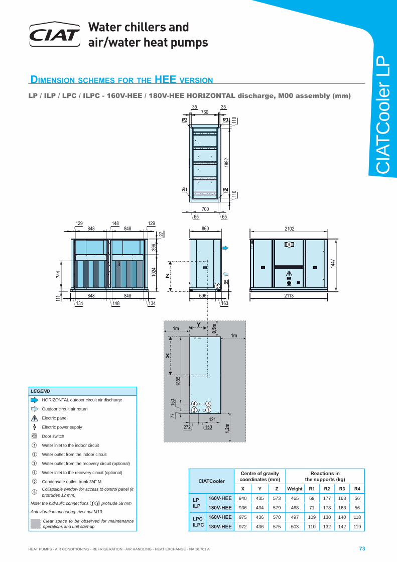
HEAT PUMPS - AIR CONDITIONING - REFRIGERATION - AIR HANDLING - HEAT EXCHANGE - NA 16.701 A
Water chillers and air/water heat pumps
73
CIA
TCoo
ler L
P
DIMENSION SCHEMES FOR THE HEE VERSION
LP / ILP / LPC / ILPC - 160V-HEE / 180V-HEE HORIZONTAL discharge, M00 assembly (mm)
CIATCoolerCentre of gravity coordinates (mm)
Reactions in the supports (kg)
X Y Z Weight R1 R2 R3 R4
LPILP
160V-HEE 940 435 573 465 69 177 163 56
180V-HEE 936 434 579 468 71 178 163 56
LPCILPC
160V-HEE 975 436 570 497 109 130 140 118
180V-HEE 972 436 575 503 110 132 142 119
110
1892
110
696163
85
2113
1447
860
1024
396
27
129848
148848
129
111
744
134848
148848
134
Z
X
Y
5
1m
1,2m
1m 0,5m
2102
421150272
1885
150
77
42 1
3
35760
35
65700
65
R1
R3
R4
R2
6
LEGEND
HORIZONTAL outdoor circuit air discharge
Outdoor circuit air return
Electric panel
Electric power supply
Door switch
1 Water inlet to the indoor circuit
2 Water outlet from the indoor circuit
3 Water outlet from the recovery circuit (optional)
4 Water inlet to the recovery circuit (optional)
5 Condensate outlet: trunk 3/4” M
6 Collapsible window for access to control panel (it protrudes 12 mm)
Note: the hidraulic connections 1 2 protrude 58 mm
Anti-vibration anchoring: rivet nut M10
Clear space to be observed for maintenance operations and unit start-up
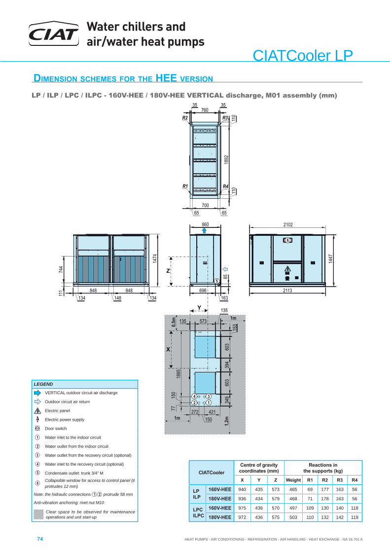
Water chillers and air/water heat pumps
HEAT PUMPS - AIR CONDITIONING - REFRIGERATION - AIR HANDLING - HEAT EXCHANGE - NA 16.701 A74
CIATCooler LPDIMENSION SCHEMES FOR THE HEE VERSION
LP / ILP / LPC / ILPC - 160V-HEE / 180V-HEE VERTICAL discharge, M01 assembly (mm)
CIATCoolerCentre of gravity coordinates (mm)
Reactions in the supports (kg)
X Y Z Weight R1 R2 R3 R4
LPILP
160V-HEE 940 435 573 465 69 177 163 56
180V-HEE 936 434 579 468 71 178 163 56
LPCILPC
160V-HEE 975 436 570 497 109 130 140 118
180V-HEE 972 436 575 503 110 132 142 119
1m
1,2m1m
0,5m
110
1892
110
696163
85
2113
1447
860
111
744
134848
148848
134
X
Y
5
349
603
394
603
153
135
573135
Z
2102
421150
272
1885
150
77
2 1
35760
35
65700
65
1474
4 3
R1
R3
R4
R2
6
LEGEND
VERTICAL outdoor circuit air discharge
Outdoor circuit air return
Electric panel
Electric power supply
Door switch
1 Water inlet to the indoor circuit
2 Water outlet from the indoor circuit
3 Water outlet from the recovery circuit (optional)
4 Water inlet to the recovery circuit (optional)
5 Condensate outlet: trunk 3/4” M
6 Collapsible window for access to control panel (it protrudes 12 mm)
Note: the hidraulic connections 1 2 protrude 58 mm
Anti-vibration anchoring: rivet nut M10
Clear space to be observed for maintenance operations and unit start-up
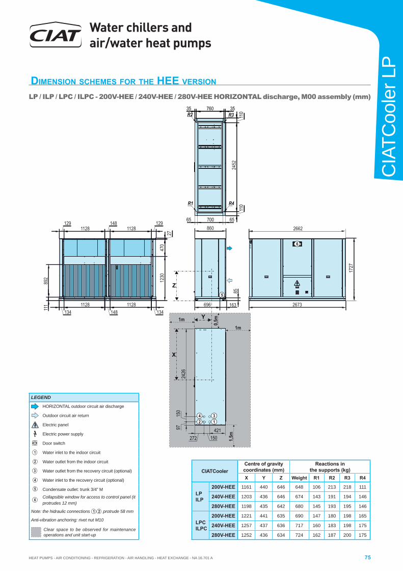
HEAT PUMPS - AIR CONDITIONING - REFRIGERATION - AIR HANDLING - HEAT EXCHANGE - NA 16.701 A
Water chillers and air/water heat pumps
75
CIA
TCoo
ler L
P
DIMENSION SCHEMES FOR THE HEE VERSION
LP / ILP / LPC / ILPC - 200V-HEE / 240V-HEE / 280V-HEE HORIZONTAL discharge, M00 assembly (mm)
CIATCoolerCentre of gravity coordinates (mm)
Reactions in the supports (kg)
X Y Z Weight R1 R2 R3 R4
LPILP
200V-HEE 1161 440 646 648 106 213 218 111
240V-HEE 1203 436 646 674 143 191 194 146
280V-HEE 1198 435 642 680 145 193 195 146
LPCILPC
200V-HEE 1221 441 635 690 147 180 198 165
240V-HEE 1257 437 636 717 160 183 198 175
280V-HEE 1252 436 634 724 162 187 200 175
X
Y
696 163
8524
52
2673
860 2662
111
892
1341128
1481128
134
1230
470
27
1291128
1481128
129
5
Z
1727
110
35 760 35R3R2
110R1 R4
6570065
1m
1,5m
1m
0,5m
2426
150
97
42 1
3
421150272
6
LEGEND
HORIZONTAL outdoor circuit air discharge
Outdoor circuit air return
Electric panel
Electric power supply
Door switch
1 Water inlet to the indoor circuit
2 Water outlet from the indoor circuit
3 Water outlet from the recovery circuit (optional)
4 Water inlet to the recovery circuit (optional)
5 Condensate outlet: trunk 3/4” M
6 Collapsible window for access to control panel (it protrudes 12 mm)
Note: the hidraulic connections 1 2 protrude 58 mm
Anti-vibration anchoring: rivet nut M10
Clear space to be observed for maintenance operations and unit start-up
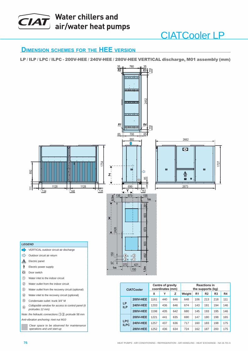
Water chillers and air/water heat pumps
HEAT PUMPS - AIR CONDITIONING - REFRIGERATION - AIR HANDLING - HEAT EXCHANGE - NA 16.701 A76
CIATCooler LPDIMENSION SCHEMES FOR THE HEE VERSION
LP / ILP / LPC / ILPC - 200V-HEE / 240V-HEE / 280V-HEE VERTICAL discharge, M01 assembly (mm)
CIATCoolerCentre of gravity coordinates (mm)
Reactions in the supports (kg)
X Y Z Weight R1 R2 R3 R4
LPILP
200V-HEE 1161 440 646 648 106 213 218 111
240V-HEE 1203 436 646 674 143 191 194 146
280V-HEE 1198 435 642 680 145 193 195 146
LPCILPC
200V-HEE 1221 441 635 690 147 180 198 165
240V-HEE 1257 437 636 717 160 183 198 175
280V-HEE 1252 436 634 724 162 187 200 175
X
Y
1m
696
8524
52
2673
860 2662
111
892
1341128
1481128
134
5
Z
1,5m1m
1727
11035 760 35
R3R2
110R1 R4
6570065
1754
603
291
135573135
673
603
492
0,5m
163
2426
150
97
42 1
3
421150
272
6
LEGEND
VERTICAL outdoor circuit air discharge
Outdoor circuit air return
Electric panel
Electric power supply
Door switch
1 Water inlet to the indoor circuit
2 Water outlet from the indoor circuit
3 Water outlet from the recovery circuit (optional)
4 Water inlet to the recovery circuit (optional)
5 Condensate outlet: trunk 3/4” M
6 Collapsible window for access to control panel (it protrudes 12 mm)
Note: the hidraulic connections 1 2 protrude 58 mm
Anti-vibration anchoring: rivet nut M10
Clear space to be observed for maintenance operations and unit start-up
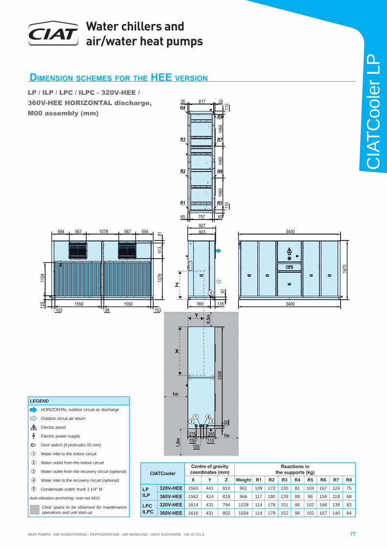
HEAT PUMPS - AIR CONDITIONING - REFRIGERATION - AIR HANDLING - HEAT EXCHANGE - NA 16.701 A
Water chillers and air/water heat pumps
77
CIA
TCoo
ler L
P
DIMENSION SCHEMES FOR THE HEE VERSION
LP / ILP / LPC / ILPC - 320V-HEE / 360V-HEE HORIZONTAL discharge, M00 assembly (mm)
R5
R6
R7
R8
R1
R2
R3
R4
Y
1m
1m
0,5m
Z
1,8m
X
110
1060
1060
1060
1103581735
6575765
3400
1970
3400
765 135
97
275150
100110265
3308
92
1376
513
81
1031550
951550
103
1104
594 567 1078 567 594 903927
125
5
42
13
CIATCoolerCentre of gravity coordinates (mm)
Reactions in the supports (kg)
X Y Z Weight R1 R2 R3 R4 R5 R6 R7 R8
LPILP
320V-HEE 1560 441 810 961 109 172 130 81 104 167 124 75
360V-HEE 1562 414 818 966 117 180 139 89 96 159 118 68
LPCILPC
320V-HEE 1614 431 794 1028 114 178 151 95 102 166 139 83
360V-HEE 1616 431 802 1034 114 179 152 96 102 167 140 84
LEGEND
HORIZONTAL outdoor circuit air discharge
Outdoor circuit air return
Electric panel
Electric power supply
Door switch (it protrudes 55 mm)
1 Water inlet to the indoor circuit
2 Water outlet from the indoor circuit
3 Water outlet from the recovery circuit (optional)
4 Water inlet to the recovery circuit (optional)
5 Condensate outlet: trunk 1 1/4” M
Anti-vibration anchoring: rivet nut M10
Clear space to be observed for maintenance operations and unit start-up
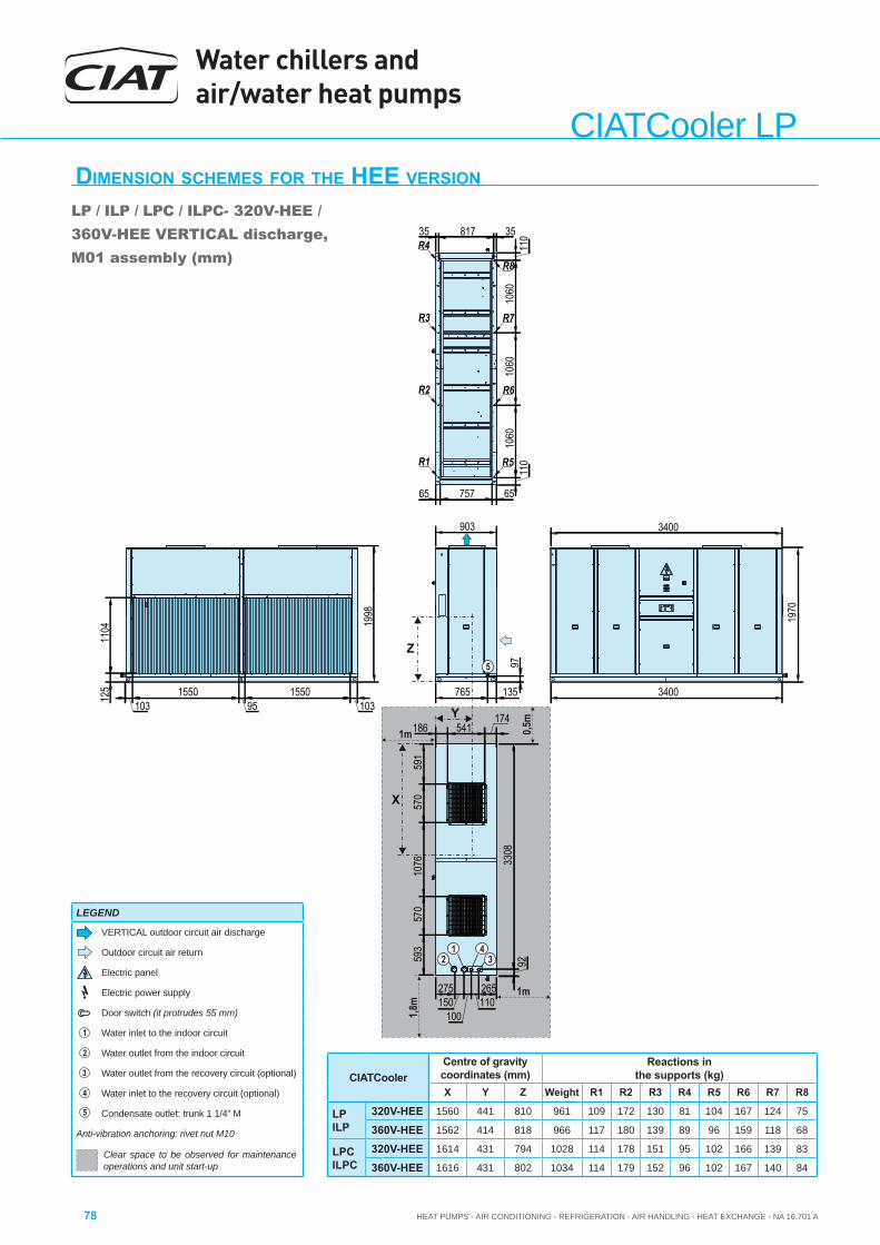
Water chillers and air/water heat pumps
HEAT PUMPS - AIR CONDITIONING - REFRIGERATION - AIR HANDLING - HEAT EXCHANGE - NA 16.701 A78
CIATCooler LPDIMENSION SCHEMES FOR THE HEE VERSION
LP / ILP / LPC / ILPC- 320V-HEE / 360V-HEE VERTICAL discharge, M01 assembly (mm)
Y
1m
1m 0,5m
Z
1,8m
X
110
1060
1060
1060
1103581735
6575765
3400
1970
3400
765 135
97
275150
100110265
3308
92
1998
1031550
951550
103
1104
125
593
570
1076
570
591
186 541174
903
R5
R6
R7
R8
R1
R2
R3
R4
5
42
13
CIATCoolerCentre of gravity coordinates (mm)
Reactions in the supports (kg)
X Y Z Weight R1 R2 R3 R4 R5 R6 R7 R8
LPILP
320V-HEE 1560 441 810 961 109 172 130 81 104 167 124 75
360V-HEE 1562 414 818 966 117 180 139 89 96 159 118 68
LPCILPC
320V-HEE 1614 431 794 1028 114 178 151 95 102 166 139 83
360V-HEE 1616 431 802 1034 114 179 152 96 102 167 140 84
LEGEND
VERTICAL outdoor circuit air discharge
Outdoor circuit air return
Electric panel
Electric power supply
Door switch (it protrudes 55 mm)
1 Water inlet to the indoor circuit
2 Water outlet from the indoor circuit
3 Water outlet from the recovery circuit (optional)
4 Water inlet to the recovery circuit (optional)
5 Condensate outlet: trunk 1 1/4” M
Anti-vibration anchoring: rivet nut M10
Clear space to be observed for maintenance operations and unit start-up

HEAT PUMPS - AIR CONDITIONING - REFRIGERATION - AIR HANDLING - HEAT EXCHANGE - NA 16.701 A
Water chillers and air/water heat pumps
79
CIA
TCoo
ler L
P
DIMENSION SCHEMES FOR THE HEE VERSION
LP / ILP / LPC / ILPC - 420V-HEE / 480-HEE / 600-HEE VERTICALdischarge, M01 assembly (mm)
Y
1m
1m 0,5m
Z
1,9m
X
R5
R6
R7
R8
R1
R2
R3
R4
1970
3600
1998
455121
147142285
1015 135
9735
1585
483
483
612
483
463
479439232
103165095
1650103
1579
110
1127
1127
1127
110
65100765
35106735
125
1150
612
463
5
4 2 13
CIATCoolerCentre of gravity (mm) Reactions in the supports (kg)
X Y Z Weight R1 R2 R3 R4 R5 R6 R7 R8
LPILP
420V-HEE 1619 553 849 1285 153 239 170 107 139 226 157 94480V-HEE 1551 537 837 1361 176 272 172 109 152 248 147 85600V-HEE 1522 527 830 1444 194 298 179 115 162 266 147 83
LPCILPC
420V-HEE 1689 538 829 1391 161 249 204 130 136 225 180 106480V-HEE 1620 524 819 1467 184 283 205 132 149 248 169 97600V-HEE 1589 515 813 1550 203 309 212 138 159 266 169 95
LEGEND
VERTICAL outdoor circuit air discharge
Outdoor circuit air return
Electric panel
Electric power supply
Door switch (it protrudes 55 mm)
1 Water inlet to the indoor circuit
2 Water outlet from the indoor circuit
3 Water outlet from the recovery circuit (optional)
4 Water inlet to the recovery circuit (optional)
5 Condensate outlet: trunk 1 1/4” M
Anti-vibration anchoring: rivet nut M10
Clear space to be observed for maintenance operations and unit start-up
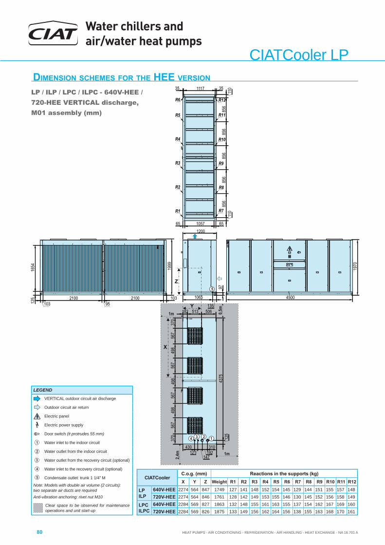
Water chillers and air/water heat pumps
HEAT PUMPS - AIR CONDITIONING - REFRIGERATION - AIR HANDLING - HEAT EXCHANGE - NA 16.701 A80
CIATCooler LP
Y
1m
1m 0,5m
Z
2,4m
X
R5
R6
R7
R8
R1
R2
R3
R4
R9
R10
R11
R12
370
567
498
567
498
567
498
567
370
430121
147192
310
35 1117 35
4375
125
110
856
856
856
856
856
110
65105765
4500
1970
1065
135
97
1999
1654
103210095
210010312
5
506513182
1200
5
4 2 13
CIATCoolerC.o.g. (mm) Reactions in the supports (kg)X Y Z Weight R1 R2 R3 R4 R5 R6 R7 R8 R9 R10 R11 R12
LPILP
640V-HEE 2274 564 847 1749 127 141 148 152 154 145 129 144 151 155 157 148720V-HEE 2274 564 846 1761 128 142 149 153 155 146 130 145 152 156 158 149
LPCILPC
640V-HEE 2284 569 827 1863 132 148 155 161 163 155 137 154 162 167 169 160720V-HEE 2284 569 826 1875 133 149 156 162 164 156 138 155 163 168 170 161
DIMENSION SCHEMES FOR THE HEE VERSION
LP / ILP / LPC / ILPC - 640V-HEE / 720-HEE VERTICAL discharge, M01 assembly (mm)
LEGEND
VERTICAL outdoor circuit air discharge
Outdoor circuit air return
Electric panel
Electric power supply
Door switch (it protrudes 55 mm)
1 Water inlet to the indoor circuit
2 Water outlet from the indoor circuit
3 Water outlet from the recovery circuit (optional)
4 Water inlet to the recovery circuit (optional)
5 Condensate outlet: trunk 1 1/4” M
Note: Models with double air volume (2 circuits): two separate air ducts are requiredAnti-vibration anchoring: rivet nut M10
Clear space to be observed for maintenance operations and unit start-up
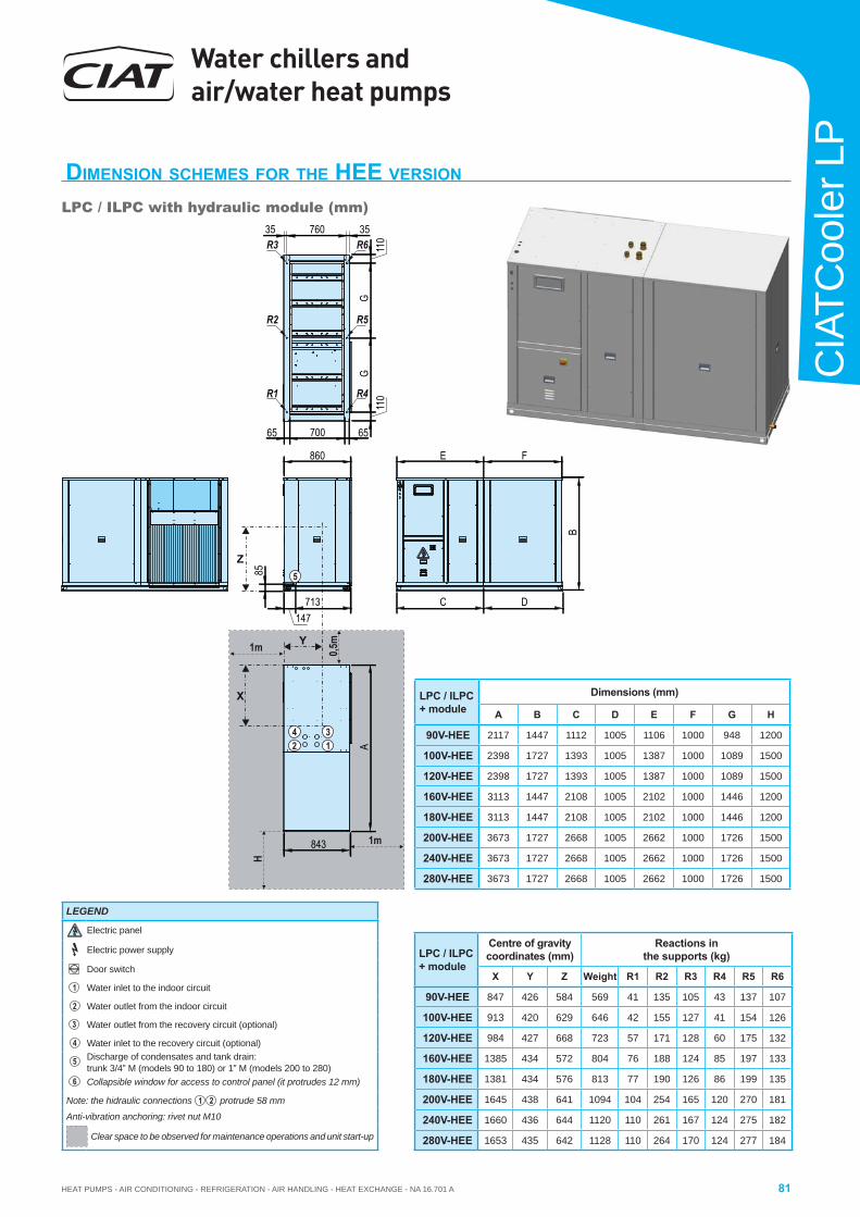
HEAT PUMPS - AIR CONDITIONING - REFRIGERATION - AIR HANDLING - HEAT EXCHANGE - NA 16.701 A
Water chillers and air/water heat pumps
81
CIA
TCoo
ler L
P
DIMENSION SCHEMES FOR THE HEE VERSION
LPC / ILPC with hydraulic module (mm)
X
Y
Z
H
C D
E F
110
6570065
GG
110
35 760 35
B
A
860
843
147713
85
R1 R4
R2 R5
R3 R6
5
42 1
3
1m
1m 0,5m
LPC / ILPC + module
Centre of gravity coordinates (mm)
Reactions in the supports (kg)
X Y Z Weight R1 R2 R3 R4 R5 R6
90V-HEE 847 426 584 569 41 135 105 43 137 107
100V-HEE 913 420 629 646 42 155 127 41 154 126
120V-HEE 984 427 668 723 57 171 128 60 175 132
160V-HEE 1385 434 572 804 76 188 124 85 197 133
180V-HEE 1381 434 576 813 77 190 126 86 199 135
200V-HEE 1645 438 641 1094 104 254 165 120 270 181
240V-HEE 1660 436 644 1120 110 261 167 124 275 182
280V-HEE 1653 435 642 1128 110 264 170 124 277 184
LPC / ILPC + module
Dimensions (mm)
A B C D E F G H
90V-HEE 2117 1447 1112 1005 1106 1000 948 1200
100V-HEE 2398 1727 1393 1005 1387 1000 1089 1500
120V-HEE 2398 1727 1393 1005 1387 1000 1089 1500
160V-HEE 3113 1447 2108 1005 2102 1000 1446 1200
180V-HEE 3113 1447 2108 1005 2102 1000 1446 1200
200V-HEE 3673 1727 2668 1005 2662 1000 1726 1500
240V-HEE 3673 1727 2668 1005 2662 1000 1726 1500
280V-HEE 3673 1727 2668 1005 2662 1000 1726 1500
LEGEND
Electric panel
Electric power supply
Door switch
1 Water inlet to the indoor circuit
2 Water outlet from the indoor circuit
3 Water outlet from the recovery circuit (optional)
4 Water inlet to the recovery circuit (optional)
5Discharge of condensates and tank drain: trunk 3/4” M (models 90 to 180) or 1” M (models 200 to 280)
6 Collapsible window for access to control panel (it protrudes 12 mm)
Note: the hidraulic connections 1 2 protrude 58 mm
Anti-vibration anchoring: rivet nut M10
Clear space to be observed for maintenance operations and unit start-up
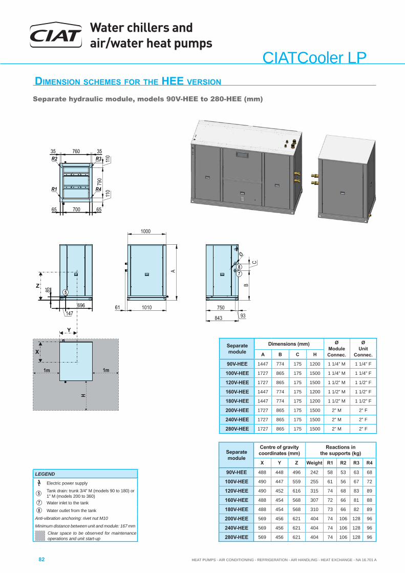
Water chillers and air/water heat pumps
HEAT PUMPS - AIR CONDITIONING - REFRIGERATION - AIR HANDLING - HEAT EXCHANGE - NA 16.701 A82
CIATCooler LP
1m
H
1m
BC
93750
790
1010
843
1000
A
35 760 35
110
110
6570065
5
78
R1 R4
R2 R3
X
Y
Z
Ø
61147
696
85
DIMENSION SCHEMES FOR THE HEE VERSION
Separate hydraulic module, models 90V-HEE to 280-HEE (mm)
Separate module
Centre of gravity coordinates (mm)
Reactions in the supports (kg)
X Y Z Weight R1 R2 R3 R4
90V-HEE 488 448 496 242 58 53 63 68
100V-HEE 490 447 559 255 61 56 67 72
120V-HEE 490 452 616 315 74 68 83 89
160V-HEE 488 454 568 307 72 66 81 88
180V-HEE 488 454 568 310 73 66 82 89
200V-HEE 569 456 621 404 74 106 128 96
240V-HEE 569 456 621 404 74 106 128 96
280V-HEE 569 456 621 404 74 106 128 96
Separate module
Dimensions (mm) Ø ModuleConnec.
Ø Unit
Connec.A B C H
90V-HEE 1447 774 175 1200 1 1/4” M 1 1/4” F
100V-HEE 1727 865 175 1500 1 1/4” M 1 1/4” F
120V-HEE 1727 865 175 1500 1 1/2” M 1 1/2” F
160V-HEE 1447 774 175 1200 1 1/2” M 1 1/2” F
180V-HEE 1447 774 175 1200 1 1/2” M 1 1/2” F
200V-HEE 1727 865 175 1500 2” M 2” F
240V-HEE 1727 865 175 1500 2” M 2” F
280V-HEE 1727 865 175 1500 2” M 2” F
LEGEND
Electric power supply
5Tank drain: trunk 3/4” M (models 90 to 180) or 1” M (models 200 to 360)
7 Water inlet to the tank
8 Water outlet from the tank
Anti-vibration anchoring: rivet nut M10
Minimum distance between unit and module: 167 mmClear space to be observed for maintenance operations and unit start-up
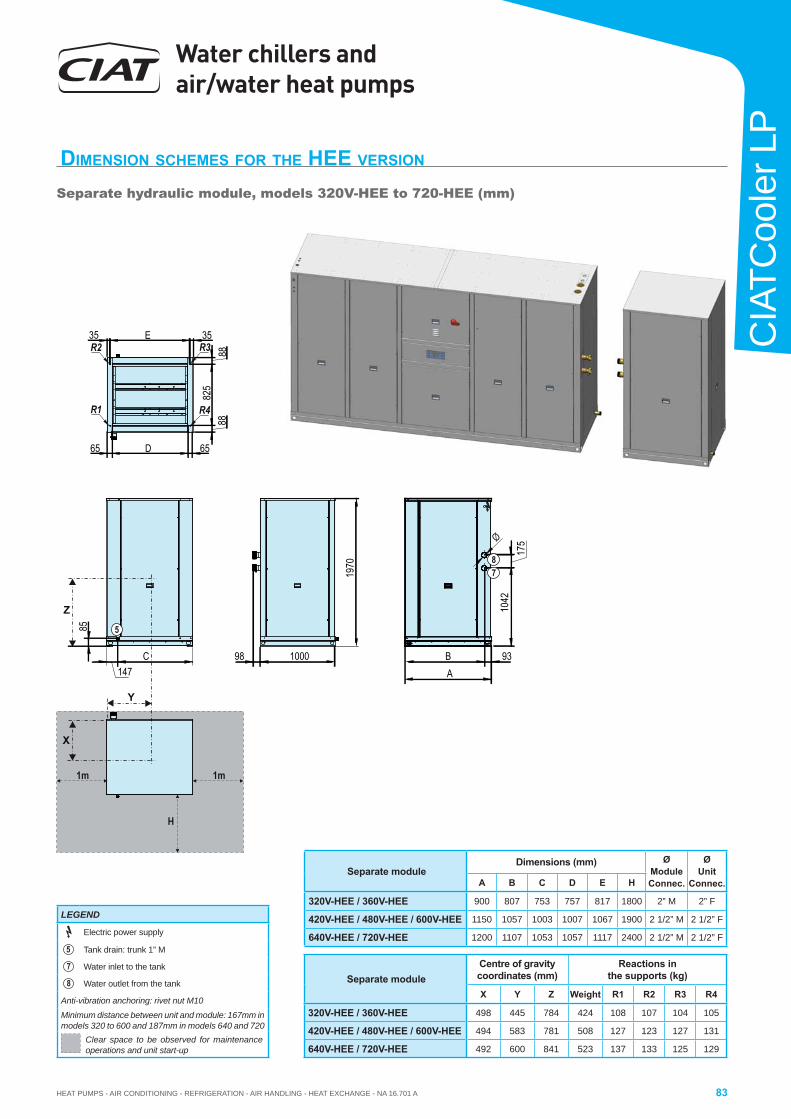
HEAT PUMPS - AIR CONDITIONING - REFRIGERATION - AIR HANDLING - HEAT EXCHANGE - NA 16.701 A
Water chillers and air/water heat pumps
83
CIA
TCoo
ler L
P1m
H
1m
C
1970
98 B 93
1042
175
1000147
Z
85 5
X
Y
Ø
78
A
65 D 65
8882
588
35 E 35
R1 R4
R2 R3
DIMENSION SCHEMES FOR THE HEE VERSION
Separate hydraulic module, models 320V-HEE to 720-HEE (mm)
Separate moduleCentre of gravity coordinates (mm)
Reactions in the supports (kg)
X Y Z Weight R1 R2 R3 R4
320V-HEE / 360V-HEE 498 445 784 424 108 107 104 105
420V-HEE / 480V-HEE / 600V-HEE 494 583 781 508 127 123 127 131
640V-HEE / 720V-HEE 492 600 841 523 137 133 125 129
Separate moduleDimensions (mm) Ø
ModuleConnec.
Ø Unit
Connec.A B C D E H
320V-HEE / 360V-HEE 900 807 753 757 817 1800 2” M 2” F
420V-HEE / 480V-HEE / 600V-HEE 1150 1057 1003 1007 1067 1900 2 1/2” M 2 1/2” F
640V-HEE / 720V-HEE 1200 1107 1053 1057 1117 2400 2 1/2” M 2 1/2” F
LEGEND
Electric power supply
5 Tank drain: trunk 1” M
7 Water inlet to the tank
8 Water outlet from the tank
Anti-vibration anchoring: rivet nut M10
Minimum distance between unit and module: 167mm in models 320 to 600 and 187mm in models 640 and 720
Clear space to be observed for maintenance operations and unit start-up
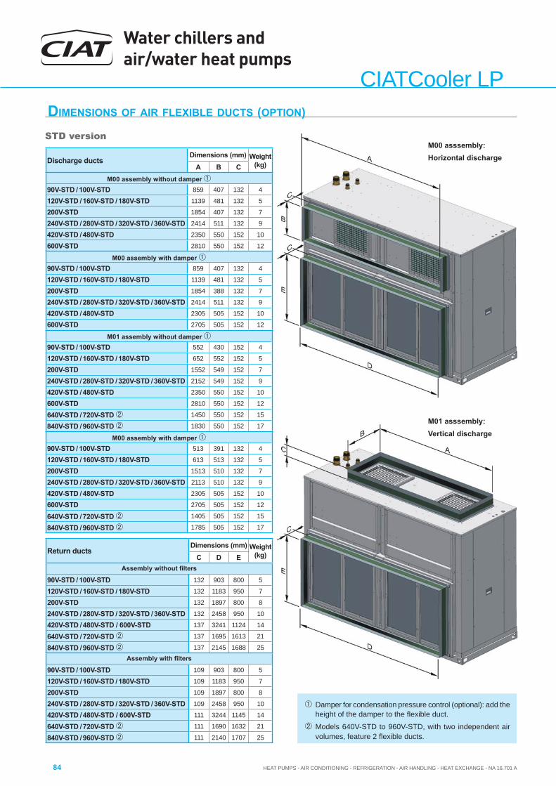
Water chillers and air/water heat pumps
HEAT PUMPS - AIR CONDITIONING - REFRIGERATION - AIR HANDLING - HEAT EXCHANGE - NA 16.701 A84
CIATCooler LPDIMENSIONS OF AIR FLEXIBLE DUCTS (OPTION)
M00 asssembly:Horizontal discharge
M01 asssembly:Vertical discharge
Damper for condensation pressure control (optional): add the height of the damper to the fl exible duct.
Models 640V-STD to 960V-STD, with two independent air volumes, feature 2 fl exible ducts.
STD version
Discharge ductsDimensions (mm) Weight
(kg)A B CM00 assembly without damper
90V-STD / 100V-STD 859 407 132 4
120V-STD / 160V-STD / 180V-STD 1139 481 132 5
200V-STD 1854 407 132 7
240V-STD / 280V-STD / 320V-STD / 360V-STD 2414 511 132 9
420V-STD / 480V-STD 2350 550 152 10
600V-STD 2810 550 152 12
M00 assembly with damper 90V-STD / 100V-STD 859 407 132 4
120V-STD / 160V-STD / 180V-STD 1139 481 132 5
200V-STD 1854 388 132 7
240V-STD / 280V-STD / 320V-STD / 360V-STD 2414 511 132 9
420V-STD / 480V-STD 2305 505 152 10
600V-STD 2705 505 152 12
M01 assembly without damper 90V-STD / 100V-STD 552 430 152 4
120V-STD / 160V-STD / 180V-STD 652 552 152 5
200V-STD 1552 549 152 7
240V-STD / 280V-STD / 320V-STD / 360V-STD 2152 549 152 9
420V-STD / 480V-STD 2350 550 152 10
600V-STD 2810 550 152 12
640V-STD / 720V-STD 1450 550 152 15
840V-STD / 960V-STD 1830 550 152 17
M00 assembly with damper 90V-STD / 100V-STD 513 391 132 4
120V-STD / 160V-STD / 180V-STD 613 513 132 5
200V-STD 1513 510 132 7
240V-STD / 280V-STD / 320V-STD / 360V-STD 2113 510 132 9
420V-STD / 480V-STD 2305 505 152 10
600V-STD 2705 505 152 12
640V-STD / 720V-STD 1405 505 152 15
840V-STD / 960V-STD 1785 505 152 17
Return ductsDimensions (mm) Weight
(kg)C D EAssembly without fi lters
90V-STD / 100V-STD 132 903 800 5
120V-STD / 160V-STD / 180V-STD 132 1183 950 7
200V-STD 132 1897 800 8
240V-STD / 280V-STD / 320V-STD / 360V-STD 132 2458 950 10
420V-STD / 480V-STD / 600V-STD 137 3241 1124 14
640V-STD / 720V-STD 137 1695 1613 21
840V-STD / 960V-STD 137 2145 1688 25Assembly with fi lters
90V-STD / 100V-STD 109 903 800 5
120V-STD / 160V-STD / 180V-STD 109 1183 950 7
200V-STD 109 1897 800 8
240V-STD / 280V-STD / 320V-STD / 360V-STD 109 2458 950 10
420V-STD / 480V-STD / 600V-STD 111 3244 1145 14
640V-STD / 720V-STD 111 1690 1632 21
840V-STD / 960V-STD 111 2140 1707 25
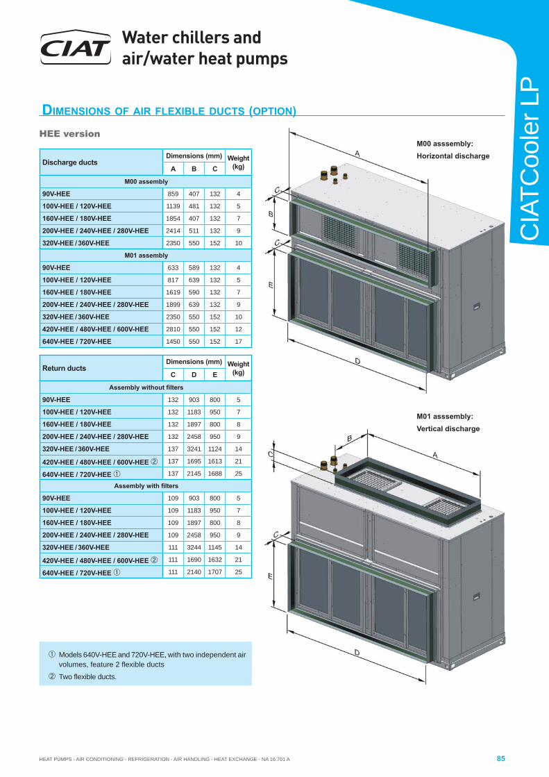
HEAT PUMPS - AIR CONDITIONING - REFRIGERATION - AIR HANDLING - HEAT EXCHANGE - NA 16.701 A
Water chillers and air/water heat pumps
85
CIA
TCoo
ler L
P
DIMENSIONS OF AIR FLEXIBLE DUCTS (OPTION)
HEE version
Discharge ductsDimensions (mm) Weight
(kg)A B C
M00 assembly
90V-HEE 859 407 132 4
100V-HEE / 120V-HEE 1139 481 132 5
160V-HEE / 180V-HEE 1854 407 132 7
200V-HEE / 240V-HEE / 280V-HEE 2414 511 132 9
320V-HEE / 360V-HEE 2350 550 152 10
M01 assembly
90V-HEE 633 589 132 4
100V-HEE / 120V-HEE 817 639 132 5
160V-HEE / 180V-HEE 1619 590 132 7
200V-HEE / 240V-HEE / 280V-HEE 1899 639 132 9
320V-HEE / 360V-HEE 2350 550 152 10
420V-HEE / 480V-HEE / 600V-HEE 2810 550 152 12
640V-HEE / 720V-HEE 1450 550 152 17
Return ductsDimensions (mm) Weight
(kg)C D E
Assembly without fi lters
90V-HEE 132 903 800 5
100V-HEE / 120V-HEE 132 1183 950 7
160V-HEE / 180V-HEE 132 1897 800 8
200V-HEE / 240V-HEE / 280V-HEE 132 2458 950 9
320V-HEE / 360V-HEE 137 3241 1124 14
420V-HEE / 480V-HEE / 600V-HEE 137 1695 1613 21
640V-HEE / 720V-HEE 137 2145 1688 25
Assembly with fi lters
90V-HEE 109 903 800 5
100V-HEE / 120V-HEE 109 1183 950 7
160V-HEE / 180V-HEE 109 1897 800 8
200V-HEE / 240V-HEE / 280V-HEE 109 2458 950 9
320V-HEE / 360V-HEE 111 3244 1145 14
420V-HEE / 480V-HEE / 600V-HEE 111 1690 1632 21
640V-HEE / 720V-HEE 111 2140 1707 25
Models 640V-HEE and 720V-HEE, with two independent air volumes, feature 2 fl exible ducts
Two fl exible ducts.
M00 asssembly:Horizontal discharge
M01 asssembly:Vertical discharge
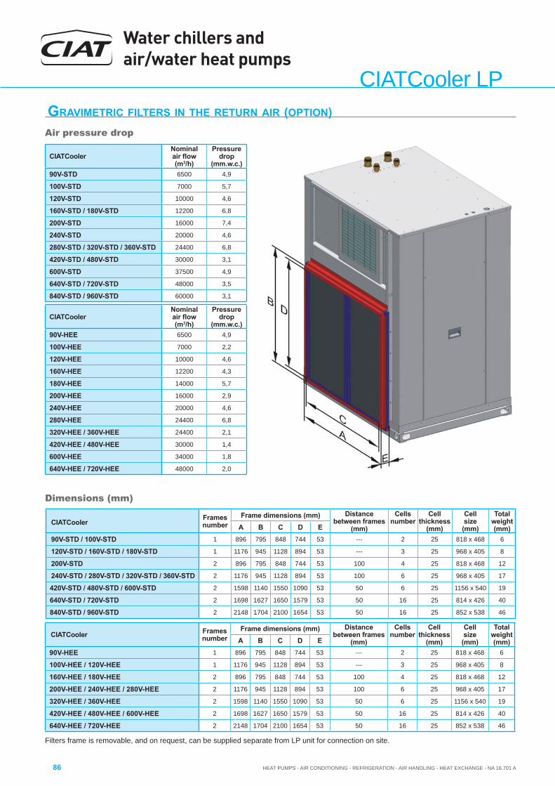
Water chillers and air/water heat pumps
HEAT PUMPS - AIR CONDITIONING - REFRIGERATION - AIR HANDLING - HEAT EXCHANGE - NA 16.701 A86
CIATCooler LPGRAVIMETRIC FILTERS IN THE RETURN AIR (OPTION)
CIATCooler Framesnumber
Frame dimensions (mm) Distance between frames
(mm)
Cellsnumber
Cell thickness
(mm)
Cell size (mm)
Total weight (mm)A B C D E
90V-STD / 100V-STD 1 896 795 848 744 53 --- 2 25 818 x 468 6
120V-STD / 160V-STD / 180V-STD 1 1176 945 1128 894 53 --- 3 25 968 x 405 8
200V-STD 2 896 795 848 744 53 100 4 25 818 x 468 12
240V-STD / 280V-STD / 320V-STD / 360V-STD 2 1176 945 1128 894 53 100 6 25 968 x 405 17
420V-STD / 480V-STD / 600V-STD 2 1598 1140 1550 1090 53 50 6 25 1156 x 540 19
640V-STD / 720V-STD 2 1698 1627 1650 1579 53 50 16 25 814 x 426 40
840V-STD / 960V-STD 2 2148 1704 2100 1654 53 50 16 25 852 x 538 46
Filters frame is removable, and on request, can be supplied separate from LP unit for connection on site.
Dimensions (mm)
Air pressure drop
CIATCooler Nominal air fl ow(m3/h)
Pressuredrop
(mm.w.c.)90V-STD 6500 4,9
100V-STD 7000 5,7
120V-STD 10000 4,6
160V-STD / 180V-STD 12200 6,8
200V-STD 16000 7,4
240V-STD 20000 4,6
280V-STD / 320V-STD / 360V-STD 24400 6,8
420V-STD / 480V-STD 30000 3,1
600V-STD 37500 4,9
640V-STD / 720V-STD 48000 3,5
840V-STD / 960V-STD 60000 3,1
CIATCooler Framesnumber
Frame dimensions (mm) Distance between frames
(mm)
Cellsnumber
Cell thickness
(mm)
Cell size (mm)
Total weight (mm)A B C D E
90V-HEE 1 896 795 848 744 53 --- 2 25 818 x 468 6
100V-HEE / 120V-HEE 1 1176 945 1128 894 53 --- 3 25 968 x 405 8
160V-HEE / 180V-HEE 2 896 795 848 744 53 100 4 25 818 x 468 12
200V-HEE / 240V-HEE / 280V-HEE 2 1176 945 1128 894 53 100 6 25 968 x 405 17
320V-HEE / 360V-HEE 2 1598 1140 1550 1090 53 50 6 25 1156 x 540 19
420V-HEE / 480V-HEE / 600V-HEE 2 1698 1627 1650 1579 53 50 16 25 814 x 426 40
640V-HEE / 720V-HEE 2 2148 1704 2100 1654 53 50 16 25 852 x 538 46
CIATCooler Nominal air fl ow(m3/h)
Pressuredrop
(mm.w.c.)90V-HEE 6500 4,9
100V-HEE 7000 2,2
120V-HEE 10000 4,6
160V-HEE 12200 4,3
180V-HEE 14000 5,7
200V-HEE 16000 2,9
240V-HEE 20000 4,6
280V-HEE 24400 6,8
320V-HEE / 360V-HEE 24400 2,1
420V-HEE / 480V-HEE 30000 1,4
600V-HEE 34000 1,8
640V-HEE / 720V-HEE 48000 2,0
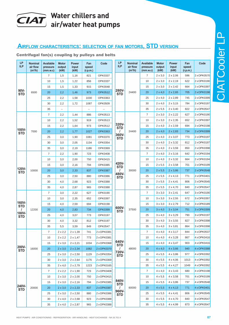
HEAT PUMPS - AIR CONDITIONING - REFRIGERATION - AIR HANDLING - HEAT EXCHANGE - NA 16.701 A
Water chillers and air/water heat pumps
87
CIA
TCoo
ler L
P
AIRFLOW CHARACTERISTICS: SELECTION OF FAN MOTORS, STD VERSION
LPILP
Nominal air fl ow(m3/h)
Available pressure(mm.w.c)
Motoroutput (kW)
Powerinput(kW)
Fan speed (r.p.m.)
Code
90V-STD 6500
7 1,5 1,16 821 OPK0337
10 1,5 1,22 856 OPK0337
15 1,5 1,33 915 OPK0048
20 2,2 1,46 973 OPK0512
25 2,2 1,58 1030 OPK0363
30 2,2 1,72 1087 OPK0509
35 -- -- --
100V-STD 7000
7 2,2 1,44 886 OPK0513
10 2,2 1,52 919 OPK0513
15 2,2 1,64 973 OPK0512
20 2,2 1,77 1027 OPK0363
25 3,0 1,90 1081 OPK0370
30 3,0 2,05 1134 OPK0354
35 3,0 2,19 1186 OPK0369
120V-STD 10000
7 2,2 1,90 723 OPK0408
10 3,0 2,00 750 OPK0415
15 3,0 2,16 794 OPK0385
20 3,0 2,33 837 OPK0387
25 3,0 2,50 880 OPK0386
30 4,0 2,68 923 OPK0388
35 4,0 2,87 965 OPK0388
160V-STD
/180V-STD
12200
7 3,0 2,22 627 OPK0190
10 3,0 2,35 652 OPK0397
15 4,0 2,59 694 OPK0198
20 4,0 2,83 734 OPK0399
25 4,0 3,07 773 OPK0197
30 4,0 3,32 812 OPK0197
35 5,5 3,59 849 OPK0547
200V-STD 16000
7 2 x 2,2 2 x 1,39 741 2 x OPK0381
10 2 x 2,2 2 x 1,47 773 2 x OPK0381
15 2 x 3,0 2 x 2,21 1034 2 x OPK0368
20 2 x 3,0 2 x 2,34 1082 2 x OPK0370
25 2 x 3,0 2 x 2,50 1129 2 x OPK0354
30 2 x 3,0 2 x 2,64 1176 2 x OPK0369
35 2 x 4,0 2 x 2,79 1223 2 x OPK0165
240V-STD 20000
7 2 x 2,2 2 x 1,90 723 2 x OPK0408
10 2 x 3,0 2 x 2,00 750 2 x OPK0415
15 2 x 3,0 2 x 2,16 794 2 x OPK0385
20 2 x 3,0 2 x 2,33 837 2 x OPK0387
25 2 x 3,0 2 x 2,50 880 2 x OPK0386
30 2 x 4,0 2 x 2,68 923 2 x OPK0388
35 2 x 4,0 2 x 2,87 965 2 x OPK0388
LPILP
Nominal air fl ow(m3/h)
Available pressure(mm.w.c)
Motoroutput (kW)
Powerinput(kW)
Fan speed (r.p.m.)
Code
280V-STD 24400
7 2 x 3,0 2 x 2,06 596 2 x OPK0570
10 2 x 3,0 2 x 2,19 622 2 x OPK0190
15 2 x 3,0 2 x 2,42 664 2 x OPK0397
20 2 x 4,0 2 x 2,65 705 2 x OPK0198
25 2 x 4,0 2 x 2,89 745 2 x OPK0399
30 2 x 4,0 2 x 3,15 784 2 x OPK0197
35 2 x 5,5 2 x 3,40 822 2 x OPK0547
320V-STD
/360V-STD
24400
7 2 x 3,0 2 x 2,22 627 2 x OPK0190
10 2 x 3,0 2 x 2,35 652 2 x OPK0397
15 2 x 4,0 2 x 2,59 694 2 x OPK0198
20 2 x 4,0 2 x 2,83 734 2 x OPK0399
25 2 x 4,0 2 x 3,07 773 2 x OPK0197
30 2 x 4,0 2 x 3,32 812 2 x OPK0197
35 2 x 4,0 2 x 3,59 850 2 x OPK0398
420V-STD
/480V-STD
30000
7 2 x 4,0 2 x 3,16 642 2 x OPK0194
10 2 x 4,0 2 x 3,32 664 2 x OPK0194
15 2 x 5,5 2 x 3,58 701 2 x OPK0199
20 2 x 5,5 2 x 3,86 737 2 x OPK0548
25 2 x 5,5 2 x 4,13 771 2 x OPK0401
30 2 x 5,5 2 x 4,41 806 2 x OPK0545
35 2 x 5,5 2 x 4,70 840 2 x OPK0547
600V-STD 37500
7 3 x 3,0 3 x 2,41 647 3 x OPK0190
10 3 x 3,0 3 x 2,55 672 3 x OPK0397
15 3 x 3,0 3 x 2,79 712 3 x OPK0189
20 3 x 4,0 3 x 3,04 751 3 x OPK0399
25 3 x 4,0 3 x 3,29 790 3 x OPK0197
30 3 x 4,0 3 x 3,55 827 3 x OPK0398
35 3 x 4,0 3 x 3,81 864 3 x OPK0398
640V-STD
/720V-STD
48000
7 4 x 4,0 4 x 3,17 844 4 x OPK0537
10 4 x 4,0 4 x 3,28 867 4 x OPK0416
15 4 x 4,0 4 x 3,47 903 4 x OPK0416
20 4 x 4,0 4 x 3,66 940 4 x OPK0388
25 4 x 5,5 4 x 3,86 977 4 x OPK0392
30 4 x 5,5 4 x 4,06 1013 4 x OPK0392
35 4 x 5,5 4 x 4,27 1049 4 x OPK0392
840V-STD
/960V-STD
60000
7 4 x 4,0 4 x 3,43 680 4 x OPK0198
10 4 x 5,5 4 x 3,58 701 4 x OPK0199
15 4 x 5,5 4 x 3,86 737 4 x OPK0548
20 4 x 5,5 4 x 4,13 771 4 x OPK0401
25 4 x 5,5 4 x 4,41 806 4 x OPK0545
30 4 x 5,5 4 x 4,70 840 4 x OPK0547
35 4 x 5,5 4 x 4,99 873 4 x OPK0547
Centrifugal fan(s) coupling by pulleys and belts
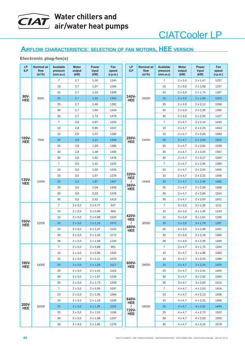
Water chillers and air/water heat pumps
HEAT PUMPS - AIR CONDITIONING - REFRIGERATION - AIR HANDLING - HEAT EXCHANGE - NA 16.701 A88
CIATCooler LPAIRFLOW CHARACTERISTICS: SELECTION OF FAN MOTORS, HEE VERSION
Electronic plug-fan(s)
LPILP
Nominal air fl ow
(m3/h)
Available pressure(mm.w.c)
Motoroutput (kW)
Powerinput(kW)
Fan speed (r.p.m.)
90V-HEE 6500
7 2,7 1,00 1240
10 2,7 1,07 1266
15 2,7 1,19 1309
20 2,7 1,33 1352
25 2,7 1,46 1392
30 2,7 1,60 1434
35 2,7 1,73 1475
100V-HEE 7000
7 2,8 0,87 1220
10 2,8 0,95 1247
15 2,8 1,07 1292
20 2,8 1,21 1344
25 2,8 1,33 1388
30 2,8 1,48 1435
35 2,8 1,62 1476
120V-HEE 10000
7 3,0 1,41 1225
10 3,0 1,50 1243
15 3,0 1,67 1276
20 3,0 1,87 1307
25 3,0 2,04 1343
30 3,0 2,23 1378
35 3,0 2,42 1413
160V-HEE 12200
7 2 x 3,0 2 x 0,77 937
10 2 x 3,0 2 x 0,85 969
15 2 x 3,0 2 x 0,98 1022
20 2 x 3,0 2 x 1,10 1072
25 2 x 3,0 2 x 1,27 1122
30 2 x 3,0 2 x 1,42 1172
35 2 x 3,0 2 x 1,58 1220
180V-HEE 14000
7 2 x 3,0 2 x 0,88 991
10 2 x 3,0 2 x 0,96 1020
15 2 x 3,0 2 x 1,11 1070
20 2 x 3,0 2 x 1,26 1117
25 2 x 3,0 2 x 1,41 1163
30 2 x 3,0 2 x 1,57 1209
35 2 x 3,0 2 x 1,73 1249
200V-HEE 16000
7 2 x 3,0 2 x 0,95 1037
10 2 x 3,0 2 x 1,05 1064
15 2 x 3,0 2 x 1,18 1106
20 2 x 3,0 2 x 1,35 1153
25 2 x 3,0 2 x 1,52 1196
30 2 x 3,0 2 x 1,68 1237
35 2 x 3,0 2 x 1,85 1278
LPILP
Nominal air fl ow
(m3/h)
Available pressure(mm.w.c)
Motoroutput (kW)
Powerinput(kW)
Fan speed (r.p.m.)
240V-HEE 20000
7 2 x 3,0 2 x 1,47 1237
10 2 x 3,0 2 x 1,58 1257
15 2 x 3,0 2 x 1,74 1287
20 2 x 3,0 2 x 1,94 1323
25 2 x 3,0 2 x 2,12 1358
30 2 x 3,0 2 x 2,30 1392
35 2 x 3,0 2 x 2,50 1427
280V-HEE 24000
7 2 x 4,7 2 x 2,14 1443
10 2 x 4,7 2 x 2,25 1454
15 2 x 4,7 2 x 2,43 1483
20 2 x 4,7 2 x 2,64 1522
25 2 x 4,7 2 x 2,84 1539
30 2 x 4,7 2 x 3,05 1567
35 2 x 4,7 2 x 3,27 1594
320V-HEE
/ 360V-HEE
24400
7 2 x 4,7 2 x 1,94 1383
10 2 x 4,7 2 x 2,04 1405
15 2 x 4,7 2 x 2,21 1436
20 2 x 4,7 2 x 2,40 1466
25 2 x 4,7 2 x 2,59 1495
30 2 x 4,7 2 x 2,80 1524
35 2 x 4,7 2 x 3,00 1551
420V-HEE
/ 480V-HEE
30000
7 3 x 3,0 3 x 1,35 1211
10 3 x 3,0 3 x 1,45 1233
15 3 x 3,0 3 x 1,61 1265
20 3 x 3,0 3 x 1,79 1297
25 3 x 3,0 3 x 1,99 1331
30 3 x 3,0 3 x 2,16 1365
35 3 x 3,0 3 x 2,35 1400
600V-HEE 34000
7 3 x 4,7 3 x 1,76 1344
10 3 x 4,7 3 x 1,86 1363
15 3 x 4,7 3 x 2,03 1394
20 3 x 4,7 3 x 2,24 1425
25 3 x 4,7 3 x 2,41 1454
30 3 x 4,7 3 x 2,62 1484
35 3 x 4,7 3 x 2,83 1514
640V-HEE
/ 720V-HEE
48000
7 4 x 4,7 4 x 2,03 1416
10 4 x 4,7 4 x 2,13 1436
15 4 x 4,7 4 x 2,31 1466
20 4 x 4,7 4 x 2,52 1494
25 4 x 4,7 4 x 2,72 1522
30 4 x 4,7 4 x 2,93 1550
35 4 x 4,7 4 x 3,15 1579
HEAT PUMPS - AIR CONDITIONING - REFRIGERATION - AIR HANDLING - HEAT EXCHANGE - NA 16.701 A
Water chillers and air/water heat pumps
89
CIA
TCoo
ler L
P
Lifting and handling operationsThe lifting and handling operations must be done in safe conditions.
Accurately follow the lifting plan present in the unit and in the user's brochure for installation, commissioning, operation, and maintenance.
Before beginning the handling, carefully check that there is suffi cient access space so that the unit can enter into the facility.
Maintenance must be done only while vertical, which is why the unit must not be laid or turned horizontally.
It is mandatory to follow the recommendations and instructions in the user's brochure for installation, commissioning, operation, and maintenance.
ASSEMBLY RECOMMENDATIONS
LocationThe CIATCooler LP / ILP / LPC / ILPC air/water heat pumps and water chillers with air-cooled condensers are units that are to be installed indoors.
Clear space must be planned around the unit (indicated on the dimensions schemes) for maintenance operations and normal operation. No obstacle may impede the air aspiration into the coil or make the outlet of the fan diffi cult.
The unit's location must be carefully studied. A suitable positioning must be selected in accordance with the demands of the surroundings (integration in the environment, noise emission, etc.) and where only authorised persons have access.
According to the guidelines in place in the place of installation, certain new air ventilation standards must be respected so as not to cause any discomfort or danger in the case of refrigerant fl uid leakage.
In the event of connection by pipes, study the network carefully (fl ows, pressure drops, speeds, etc.). A poorly studied network (excessive speeds, poor stiffness, etc.) can cause a signifi cant sound level.
LP / ILP units must have the ducted supply. The weight of an air discharge pipe must not rest on the unit at any time.
The pipe must ensure that the people in front of the fan are protected.
In particular, avoid installing the units in areas where those under the age of 14 could come into contact with them. If necessary, access to the units will be protected using a suitable enclosure or fencing.
All of the units are fully charged with refrigerant and tested in the factory.
Safety devicesThe units have the necessary control and safety elements; cold water temperature controlling, water circulation controller, anti-freeze safety, high- and low-pressure pressostats, anti-short-cycle timing, compressor and ventilator thermal protection, etc.
Electrical connectionsThe indications required for the electrical connections are indicated on the electrical diagram enclosed with the unit.
These connections are always established as per the norms in force. The electric and control panel is completely wired. Only the main electric power supply has to be set up (the engineer must plan for the protections: main switch, differential switch, etc.).
The installer must perform a command remotely from the unit and have operation and failure indicators.
Plan a switch for selecting the operation mode (cooling-heating) for the reversible units.
It is important to remember that the unit is not protected against radiation, from the electrical point of view. Therefore, safety devices to protect against these temporary phenomena must be placed in the installation and incorporated into the electrical supply panel.
Water quality criteriaWarning: During installation, it is mandatory that an 500 micron water be placed in the unit's water inlet.
The proper and suitable operation of a cold/hot water production unit with a respectable useful life depends directly on the quality of the water used, particularly if the water can cause phenomena such as clogging, corrosion, formation of algae or micro-organisms.
It is mandatory to analyse the water in order to verify that it can be used in the unit and to determine whether a chemical treatment will be suffi cient to confer an acceptable quality level or whether a softening and demineralisation system is necessary.
This analysis must confi rm whether or not the water present in the work is compatible with the following nomenclature for the various materials present in the CIAT GROUP unit circuit:
- 99.9% copper tubes with copper and silver welding
- Bronze threaded hoses
- AISI 316 - 1.4401 stainless steel plate exchangers and connections with copper and silver welding
Warning: If these instructions are not respected, the unit's warranty shall lose its validity.
Water chillers and air/water heat pumps
HEAT PUMPS - AIR CONDITIONING - REFRIGERATION - AIR HANDLING - HEAT EXCHANGE - NA 16.701 A90
CIATCooler LP
Hydraulic connectionsThe direction of water circulation must be observed as indicated on the unit.
Plan the anti-freeze protection for the unit and the installation when the outdoor temperature is low and the unit does not function: water with anti-freeze, draining the installation, etc.
In installations to open circuits, if it is not possible to maintain the water conditions within the values indicated in the corrosion behaviour table, it will be necessary to install an exchanger that separates the unit circuit from the circuit of the water circuit to be dealt with by using materials compatible with these characteristics, whether stainless steel or titanium.
The tubes must not transmit any force or vibrations to the water exchanger. It is advisable to use fl exible hoses for connecting the piping to the unit in order to reduce the transmission of vibrations to the building to the greatest degree. It is mandatory to assemble hoses if the unit is installed over antivibration mounts.
Problems in commissioningProblems could occur during the start of the units' operation if the conditions under which the start is performed are not suitable:
• Insuffi cient water fl ow. Very high temperature differences between water inlet into and outlet from the unit caused by:
- Insuffi cient air bleeding.
- Small water circulation pump or anti-clockwise rotation.
- Other situations which may prevent correct water circulation.
• Insuffi cient thermal charge in the installation. The limiting operating values are quickly reached by:
- Incorrect operation of the emissions system (fan coils, air conditioning exchangers, etc.).
• Air recirculation in the unit caused by an obstacle in the air aspiration or in its outlet.
To prevent such problems, the electric and hydraulic connections must be verifi ed prior to starting the unit, checking the correct operation of the water circulation pump, the fi lling and draining of the hydraulic circuit, etc.
It is necessary to maintain the main electric supply to the unit for 24 hours before starting it so that the compressor's crankcase heater may start.
When the unit is operating, its main power supply must not be cut. The shutdown must be done from a remote command. The crankcase heater must always be with voltage (except for prolonged shut-downs of the unit).
Note: Check that the water fl ow in the circuit is constant and suffi cient (see evaporator operation limit). In case there should be a variation in the fl ow (control by two-way valves, closing and opening circuits), it is necessary to assemble a pressure differential valve or circulation pumps on each circuit.
Warnings:
- Ensure that the pressure of the water circuits is below 4.0 bars.
- Place the expansion vessel in front of the pump.
- Do not assembly any valve on the expansion vessel.
- Ensure that the water circulation pumps are located in the entrance of the plate exchangers.
- Ensure that the water pressure in the aspiration of the circulation pumps is equal to or greater than the minimum nominal pressure (NPSHR), particularly in the case of an "open" hydraulic circuit.
- Analyse the water quality criteria in accordance with the technical recommendations.
- Plan the anti-freeze protections that the unit and the hydraulic installations need, such as the possibility of purging the circuit. In the presence of glycol for anti-freeze protection, it is mandatory to supervise its nature and concentration prior to commissioning.
- Before making the fi nal hydraulic connections, rinse the tubes with clean water to remove impurities.
CommissioningNon-exhaustive list of operations that must be performed during commissioning:
- Check for the proper installation of the unit.
- Check for electrical power supply protection.
- Check for phases and the direction of rotation.
- Verifi cation of the electronic wiring of the unit.
- Check of the water circulation direction in the unit.
- Verifi cation of the cleanliness of the hydraulic circuit.
- Control of the water fl ow according to the specifi ed value.
- Check of the cooling circuit pressures.
- Verifi cation of the rotation direction of the compressors.
- Check of the pressure drops and the water fl ow drops.
- Report on the operating values
Hydraulic circuitAll essential accessories for the hydraulic circuits must be planned (expansion vessel, air bleeder valves, safety valve, cut-off valve, drainage holes, thermometers, etc.).
Check the water content of the installation, if necessary, to plan a buffer tank.
It is also necessary to install a fi lter (supplied in the LPC / ILPC kit) in the hydraulic power supply to the unit (for particulates of Ø > 500 microns) in order to prevent clogging of the plate exchanger (this can cause a decrease in fl ow that could lead to freezing and breaking the exchanger).


