OPERATING, MAINTENANCE & PARTS MANUAL AIR CHAIN HOIST Manual No. A652-D Before installing hoist, fill in the information below. Refer to the hoist identification plate. Model No. __________________ Serial No. __________________ Purchase Date ______________ Rated Capacity______________ 53031 AIR XL CHAIN HOIST Rated capacities 2 through 7½ tons/ 2000 through 7500 kg Follow all instructions and warnings for inspecting, maintaining and operating this hoist. The use of any hoist presents some risk of personal injury or property damage. That risk is greatly increased if proper instructions and warnings are not followed. Before using this hoist, each operator should become thoroughly familiar with all warnings, instructions and recommendations in this manual. Retain this manual for future reference and use. Forward this manual to operator. Failure to operate equipment as directed in manual may cause injury. ®
Transcript
OPERATING,
MAINTENANCE
& PARTS
MANUAL
AIR
CHAIN HOIST
Manual No. A652-D
Before installing hoist, fill inthe information below. Referto the hoist identificationplate.
Model No. __________________
Serial No. __________________
Purchase Date ______________
Rated Capacity______________
53031
AAIIRR XXLL CCHHAAIINNHHOOIISSTT
Rated capacities 2 through 7½ tons/2000 through 7500 kg
Follow all instructions and warnings for inspecting, maintaining and operating this hoist.The use of any hoist presents some risk of personalinjury or property damage. That risk is greatlyincreased if proper instructions and warnings are notfollowed. Before using this hoist, each operatorshould become thoroughly familiar with all warnings,instructions and recommendations in this manual.Retain this manual for future reference and use.
Forward this manual to operator. Failure to operate equipment as directedin manual may cause injury.
®
XL AIR HOIST PARTS AND SERVICES ARE AVAILABLE IN THE UNITED STATES AND IN CANADA
As a XL Air Hoist user, you are assured of reliable repair and parts services through a network of Master Parts Depots andService Centers that are strategically located in the United States and Canada. These facilities have been selected on thebasis of their demonstrated ability to handle all parts and repair requirements promptly and efficiently.
Below is a list of the Master Parts Depots in the United States and Canada. To quickly obtain the name of the U.S. ServiceCenter located nearest you, call (800) 888-0985. Fax: (716) 689-5644. In the following list, the Canadian Service Centers are indicated.
i
UNITED STATES MASTER PARTS DEPOT CANADIAN SERVICE CENTERS
CALIFORNIAOTTO SYSTEMS, INC.12010 Bloomfield Ave.Sante Fe Springs, CA 90670562/462-1612 or 800/596-7392Fax 562/462-1617or7656 Las Positas RoadLivemore, CA 94551925/245-8800 or 800/508-68860 Fax 925/245-8804
GEORGIAACE INDUSTRIES, INC.6295 McDonough DriveNorcross, GA 30093770/441-0898 or 800/733-2231Fax 800/628-3648
ILLINOISJOHN SAKASH COMPANY, INC.700 Walnut StreetElmhurst, IL 60126630/833-3940Fax 630-833-9830
INDIANAHORNER ELECTRIC COMPANY, INC.1521 East Washington StreetIndianapolis, IN 46201317/639-4261Fax 317/639-4342
IOWAVM HOIST & CRANE SERVICESPO Box 440Walford, IA 52351319/846-6040Fax 319/846-6045
KANSASINDEPENDENT ELECTRIC MACHINERY4425 Oliver StreetKansas City, KS 66106913/362-1155 or 800/833-2610Fax 913/904-3330
LOUISIANABEERMAN PRECISION, INC.PO Box 6018Metairie, LA 70009504/207-6000Fax 504/207-6044
MASSACHUSETTSABEL DISTRIBUTORS, INC.50 Parker Street, Unit 2Newburyport, MA 01950978/463-0700Fax 978/463-5200
NEW JERSEYSHUPPER-BRICKLE EQUIPMENT CO.PO Box 8032394 Route 130, Suite CDayton, NJ 08810732/438-3888Fax 732/438-3889
NEW YORKVOLLAND ELECTRIC EQUIPMENT CO.75 Innsbruck DriveBuffalo, NY 14227716/656-9900Fax 716/656-8899
NORTH CAROLINATEAM SESCO2225 Freedom DriveCharlotte, NC 28208704/372-4832 or 800/487-3726Fax 704/358-1098
OHIOMAZZELLA LIFTING TECHNOLOGIES21000 Aerospace ParkwayCleveland, OH 44142-1072440/239-7000 or 800/362-4601Fax 440/239-7010
PENNSYLVANIAAMICK ASSOCIATES, INC.11 Sycamore StreetPO Box 529Carnegie, PA 15106-0529412/429-1212 or 800/445-9456Fax 412/429-0191
*LEGER PALANS ET OUTILLAGES, INC.7995-17th Ave.Montreal, Quebec H1Z 3R2514/376-3050Fax 514/376-0657
**ARE ALSO MASTER PARTS DEPOTS
**MASTER PARTS DEPOT ONLY
�� ! WARNINGUsage of hoists that do not involve lifting of the loadon the lower hook or using hoists in the inverted posi-tion without special precaution may cause an accidentresulting in injury and/or property damage.
TO AVOID INJURY:Consult Factory for information concerning using hoists inthese applications.
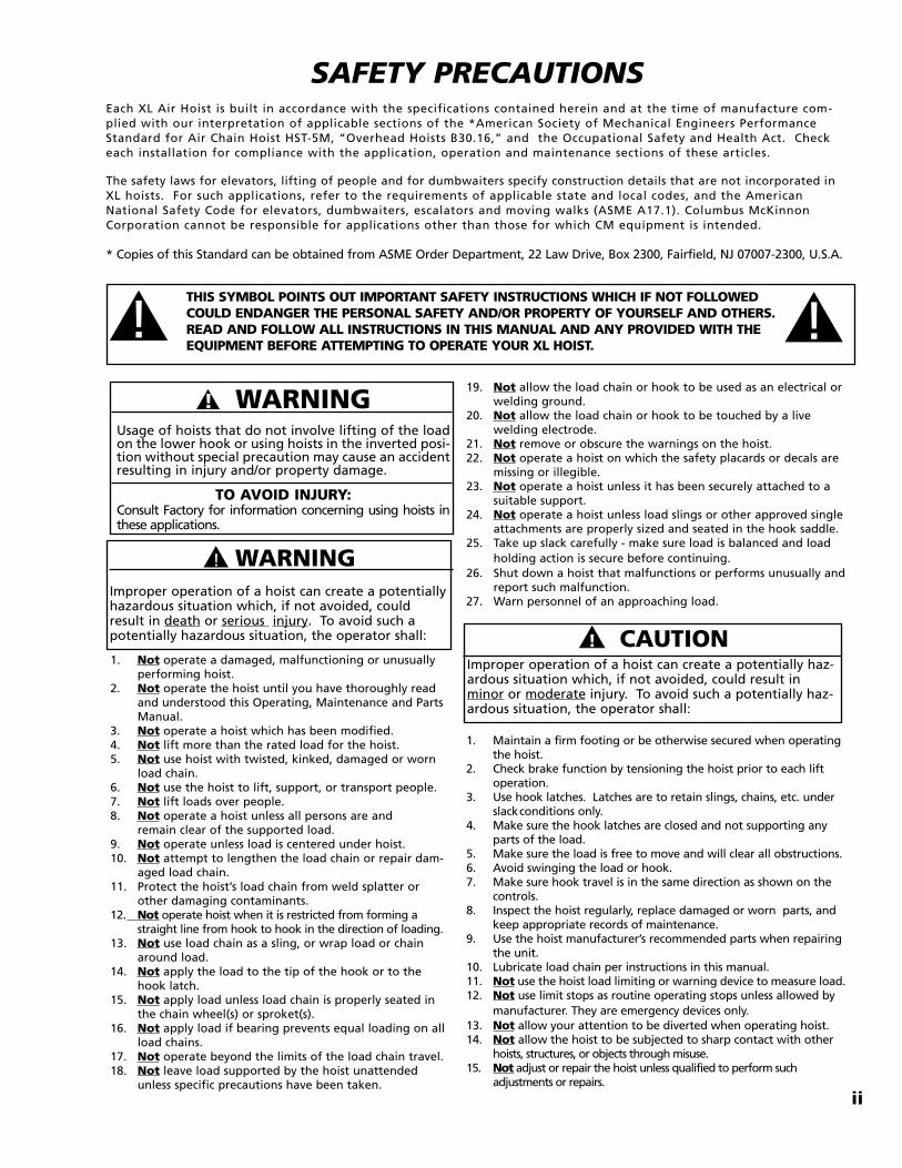
SAFETY PRECAUTIONSEach XL Air Hoist is built in accordance with the specifications contained herein and at the time of manufacture com-plied with our interpretation of applicable sections of the *American Society of Mechanical Engineers PerformanceStandard for Air Chain Hoist HST-5M, “Overhead Hoists B30.16,” and the Occupational Safety and Health Act. Checkeach installation for compliance with the application, operation and maintenance sections of these articles.
The safety laws for elevators, lifting of people and for dumbwaiters specify construction details that are not incorporated inXL hoists. For such applications, refer to the requirements of applicable state and local codes, and the AmericanNational Safety Code for elevators, dumbwaiters, escalators and moving walks (ASME A17.1). Columbus McKinnonCorporation cannot be responsible for applications other than those for which CM equipment is intended.
* Copies of this Standard can be obtained from ASME Order Department, 22 Law Drive, Box 2300, Fairfield, NJ 07007-2300, U.S.A.
ii
19. Not allow the load chain or hook to be used as an electrical or welding ground.
20. Not allow the load chain or hook to be touched by a livewelding electrode.
21. Not remove or obscure the warnings on the hoist.22. Not operate a hoist on which the safety placards or decals are
missing or illegible.23. Not operate a hoist unless it has been securely attached to a
suitable support.24. Not operate a hoist unless load slings or other approved single
attachments are properly sized and seated in the hook saddle.25. Take up slack carefully - make sure load is balanced and load
holding action is secure before continuing.26. Shut down a hoist that malfunctions or performs unusually and
report such malfunction.27. Warn personnel of an approaching load.
1. Not operate a damaged, malfunctioning or unusually performing hoist.
2. Not operate the hoist until you have thoroughly read and understood this Operating, Maintenance and PartsManual.
3. Not operate a hoist which has been modified.4. Not lift more than the rated load for the hoist.5. Not use hoist with twisted, kinked, damaged or worn
load chain.6. Not use the hoist to lift, support, or transport people.7. Not lift loads over people.8. Not operate a hoist unless all persons are and
remain clear of the supported load.9. Not operate unless load is centered under hoist.10. Not attempt to lengthen the load chain or repair dam-
aged load chain.11. Protect the hoist’s load chain from weld splatter or
other damaging contaminants.12. Not operate hoist when it is restricted from forming a
straight line from hook to hook in the direction of loading.13. Not use load chain as a sling, or wrap load or chain
around load.14. Not apply the load to the tip of the hook or to the
hook latch.15. Not apply load unless load chain is properly seated in
the chain wheel(s) or sproket(s).16. Not apply load if bearing prevents equal loading on all
load chains.17. Not operate beyond the limits of the load chain travel.18. Not leave load supported by the hoist unattended
unless specific precautions have been taken.
�! WARNINGImproper operation of a hoist can create a potentially hazardous situation which, if not avoided, couldresult in death or serious injury. To avoid such apotentially hazardous situation, the operator shall: �� ! CAUTION
Improper operation of a hoist can create a potentially haz-ardous situation which, if not avoided, could result inminor or moderate injury. To avoid such a potentially haz-ardous situation, the operator shall:
1. Maintain a firm footing or be otherwise secured when operating the hoist.
2. Check brake function by tensioning the hoist prior to each lift operation.
3. Use hook latches. Latches are to retain slings, chains, etc. underslackconditions only.
4. Make sure the hook latches are closed and not supporting anyparts of the load.
5. Make sure the load is free to move and will clear all obstructions.6. Avoid swinging the load or hook.7. Make sure hook travel is in the same direction as shown on the
controls.8. Inspect the hoist regularly, replace damaged or worn parts, and
keep appropriate records of maintenance.9. Use the hoist manufacturer’s recommended parts when repairing
the unit.10. Lubricate load chain per instructions in this manual.11. Not use the hoist load limiting or warning device to measure load.12. Not use limit stops as routine operating stops unless allowed by
manufacturer. They are emergency devices only.13. Not allow your attention to be diverted when operating hoist.14. Not allow the hoist to be subjected to sharp contact with other
hoists, structures, or objects through misuse.15. Not adjust or repair the hoist unless qualified to perform such
adjustments or repairs.
� !THIS SYMBOL POINTS OUT IMPORTANT SAFETY INSTRUCTIONS WHICH IF NOT FOLLOWEDCOULD ENDANGER THE PERSONAL SAFETY AND/OR PROPERTY OF YOURSELF AND OTHERS.READ AND FOLLOW ALL INSTRUCTIONS IN THIS MANUAL AND ANY PROVIDED WITH THEEQUIPMENT BEFORE ATTEMPTING TO OPERATE YOUR XL HOIST.
� !
iii
1
ITEM PAGE NO.MASTER PARTS DEPOTS AND SERVICE CENTERS. . . . .i
FOREWORDThis manual contains important information to help you properly install, operate and maintain your hoist for maximumperformance, economy and safety.
Please study its contents thoroughly before putting your hoist into operation. By practicing correct operating proce-dures and by carrying out the recommended preventative maintenance suggestions, you will experience long, depend-able and safe service. After you have completely familiarized yourself with the contents of this manual, we recommendthat you carefully file it for future reference.
The information herein is directed to the proper use, care and maintenance of the hoist and does not comprise a hand-book on the broad subject of rigging. Rigging can be defined as the process of lifting or moving heavy loads usinghoist and other mechanical equipment. Skill acquired through specialized experience and study is essential to safe rig-ging operations. For rigging information, we recommend consulting a standard textbook on the subject.
TABLE OF CONTENTS
SPECIFICATIONS
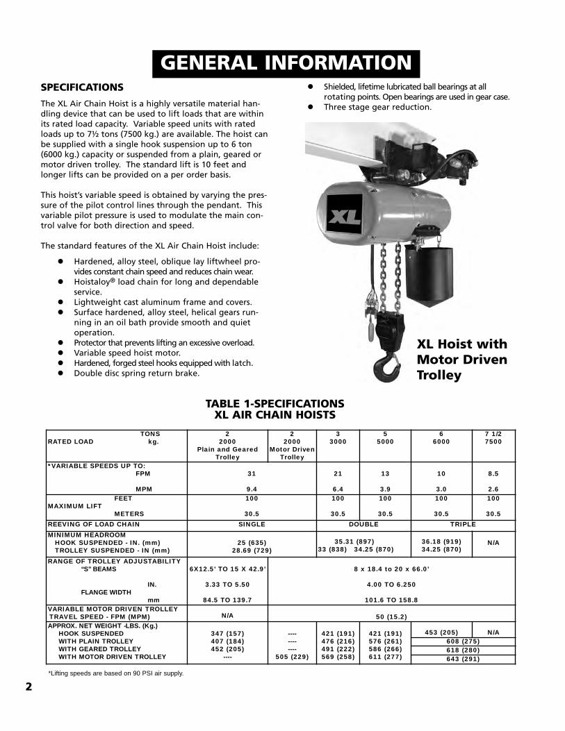
The XL Air Chain Hoist is a highly versatile material han-dling device that can be used to lift loads that are withinits rated load capacity. Variable speed units with ratedloads up to 7½ tons (7500 kg.) are available. The hoist canbe supplied with a single hook suspension up to 6 ton(6000 kg.) capacity or suspended from a plain, geared ormotor driven trolley. The standard lift is 10 feet andlonger lifts can be provided on a per order basis.
This hoist’s variable speed is obtained by varying the pres-sure of the pilot control lines through the pendant. Thisvariable pilot pressure is used to modulate the main con-trol valve for both direction and speed.
The standard features of the XL Air Chain Hoist include:
ning in an oil bath provide smooth and quiet operation.
� Protector that prevents lifting an excessive overload.� Variable speed hoist motor. � Hardened, forged steel hooks equipped with latch.� Double disc spring return brake.
2
TABLE 1-SPECIFICATIONSXL AIR CHAIN HOISTS
GENERAL INFORMATION
XL Hoist withMotor DrivenTrolley
*Lifting speeds are based on 90 PSI air supply.
� Shielded, lifetime lubricated ball bearings at all rotating points. Open bearings are used in gear case.
� Three stage gear reduction.
TONSRATED LOAD kg.
22000
Plain and GearedTrolley
22000
Motor DrivenTrolley
33000
55000
66000
7 1/27500
*VARIABLE SPEEDS UP TO:FPM
MPM
31
9.4
21
6.4
13
3.9
10
3.0
8.5
2.6FEET
MAXIMUM LIFTMETERS
100
30.5
100
30.5
100
30.5
100
30.5
100
30.5REEVING OF LOAD CHAIN SINGLE DOUBLE TRIPLEMINIMUM HEADROOMHOOK SUSPENDED - IN. (mm)TROLLEY SUSPENDED - IN (mm)
25 (635)28.69 (729)
35.31 (897)33 (838) 34.25 (870)
36.18 (919)34.25 (870)
N/A
RANGE OF TROLLEY ADJUSTABILITY“S” BEAMS
IN.FLANGE WIDTH
mm
6X12.5’ TO 15 X 42.9’
3.33 TO 5.50
84.5 TO 139.7
8 x 18.4 to 20 x 66.0’
4.00 TO 6.250
101.6 TO 158.8VARIABLE MOTOR DRIVEN TROLLEYTRAVEL SPEED - FPM (MPM) N/A 50 (15.2)APPROX. NET WEIGHT -LBS. (Kg.)
HOOK SUSPENDEDWITH PLAIN TROLLEYWITH GEARED TROLLEYWITH MOTOR DRIVEN TROLLEY
347 (157)407 (184)452 (205)
----
------------
505 (229)
421 (191)476 (216)491 (222)569 (258)
421 (191)576 (261)586 (266)611 (277)
453 (205) N/A608 (275)618 (280)643 (291)
REPAIR/REPLACEMENT POLICY
All XL Air Chain Hoists are thoroughly inspected and perfor-mance tested prior to shipment. If any properly maintainedhoist develops a performance problem due to a material orworkmanship defect, as verified by factory, repair orreplacement of the unit will be made to the original pur-chaser without charge. This repair/replacement policyapplies only to XL Hoists installed, maintained and operatedas outlined in this manual, and specifically excludes parts sub-ject to normal wear, abuse, improper installation, improperor inadequate maintenance, hostile environmental effectsand unauthorized repairs/modifications.
We reserve the right to change materials or design if, in ouropinion, such changes will improve our product. Abuse,repair by an unauthorized person, or use of non-factoryreplacement parts voids the guarantee and could lead todangerous operation. For full Terms of Sale, see Sales OrderAcknowledgement. Also, refer to the back cover forLimitations of Warranties, Remedies and Damages, andIndemnification and Safe Operation.
ACCESSORIESHOOK SUSPENSIONSHook suspensions are available for suspending 2 through 6ton hoist from a trolley with a single load bar or for sus-pending the hoist from a fixed structure.
3
LUG SUSPENSIONSLug suspensions are required to suspend the XL Air Hoistfrom plain, geared or motor driven trolleys describedbelow. When the hoist is to be suspended from a plain,geared or motor driven trolley, the lug suspension isattached to the hoist prior to shipment.
LUG SUSPENSION
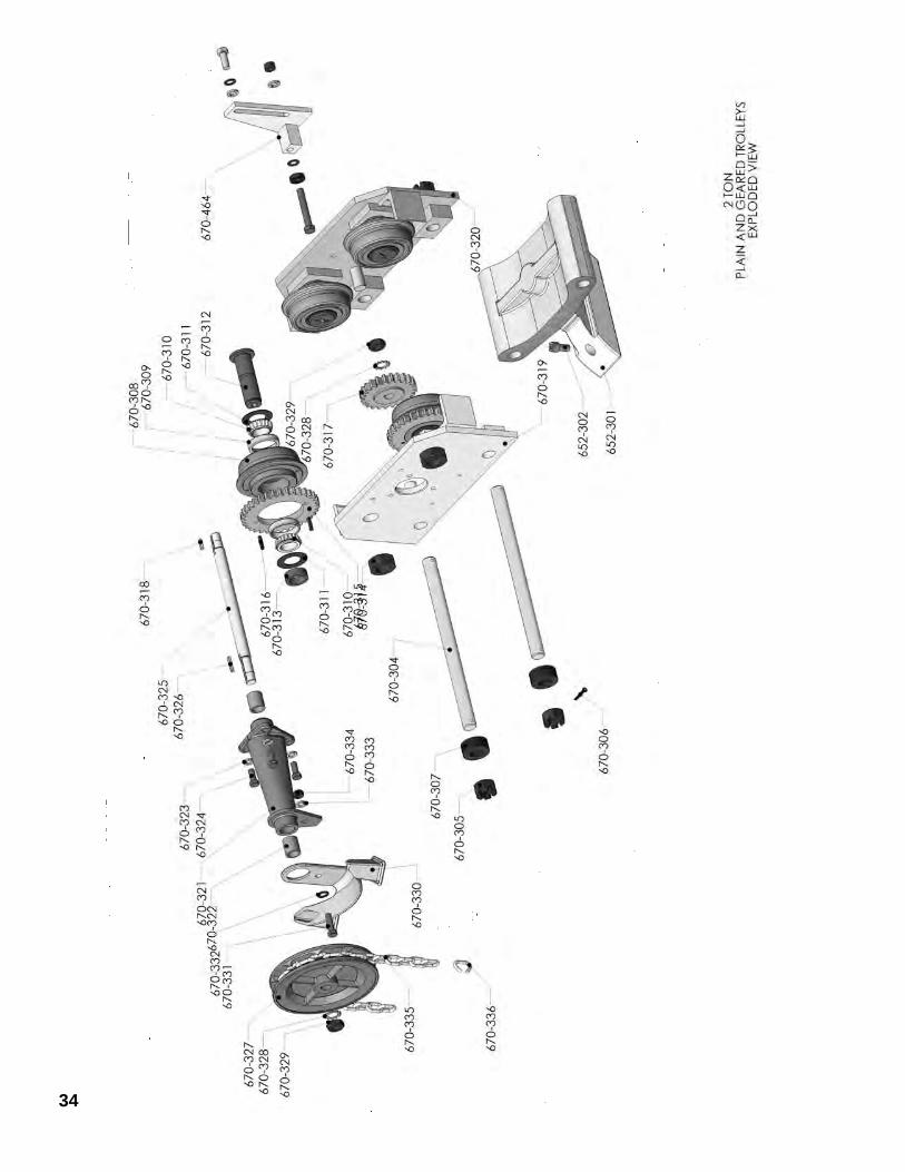
PLAIN TROLLEYSThese are manual push type trolleys designed for use withthe XL Air Hoist. The trolley is adjustable to operate on arange of American Standard ‘S’ beams and flat flangedbeams. The plain trolley is mounted on the hoist prior toshipment.
PLAIN TROLLEY
GEARED TROLLEYSThe geared trolley is similar to the plain trolley except it ismoved by the means of a hand chain. The hand chainrotates a pinion that drives gears attached to trolleywheels and moves trolley along the beam. The geared trol-ley is mounted on the hoist prior to shipment.
MOTOR DRIVEN TROLLEYSThe motor driven trolley is similar to the geared trolleyexcept the hand chain wheel is replaced with a gearreducer and an air motor. The motor is controlled by abidirectional valve mounted to the motor and it is con-trolled by levers located on the pendant control station.A variable speed motor driven trolley is mounted on thehoist prior to shipment.
2 ton 3-6 tonHOOK SUSPENSION
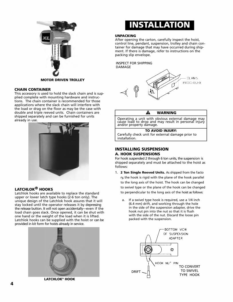
CHAIN CONTAINERThis accessory is used to hold the slack chain and is sup-plied complete with mounting hardware and instruc-tions. The chain container is recommended for thoseapplications where the slack chain will interfere withthe load or drag on the floor as may be the case withdouble and triple reeved units. Chain containers areshipped separately and can be furnished for unitsalready in use.
4
LATCHLOK® HOOKSLatchlok hooks are available to replace the standardupper or lower latch type hooks (2-6 ton only). Theunique design of the Latchlok hook assures that it willstay locked until the operator releases it by depressingthe release button. It will not open accidentally—even if theload chain goes slack. Once opened, it can be shut withone hand or the weight of the load when it is lifted.Latchlok hooks can be supplied with the hoist or can beprovided in kit form for hoists already in service.
LATCHLOK® HOOK
INSTALLATIONUNPACKINGAfter opening the carton, carefully inspect the hoist,control line, pendant, suspension, trolley and chain con-tainer for damage that may have occurred during ship-ment. If there is damage, refer to instructions on thepacking slip envelope.
INSTALLING SUSPENSIONA. HOOK SUSPENSIONSFor hook suspended 2 through 6 ton units, the suspension isshipped separately and must be attached to the hoist asfollows:
1. 2 Ton Single Reeved Units. As shipped from the facto
ry, the hook is rigid with the plane of the hook parallel
to the long axis of the hoist. The hook can be changed
to swivel type or the plane of the hook can be changed
to perpendicular to the long axis of the hoist as follows:
a. If a swivel type hook is required, use a 1/4 inch (6.4 mm) drift, and working through the hole in the side of the suspension adapter, drive the hook nut pin into the nut so that it is flush with the side of the nut. Discard the loose pin packed with the suspension.
��! WARNINGOperating a unit with obvious external damage maycause load to drop and may result in personal injuryand/or property damage.
TO AVOID INJURY:Carefully check unit for external damage prior toinstallation.
INSPECT FOR SHIPPINGDAMAGE
MOTOR DRIVEN TROLLEY
TO CONVERTTO SWIVELTYPE HOOK
DRIFT
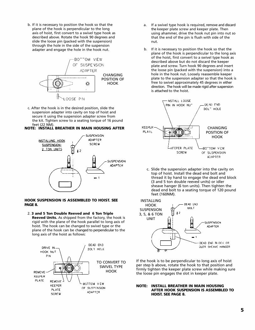
a. If a swivel type hook is required, remove and discard the keeper plate screw and keeper plate. Then using ahammer, drive the hook nut pin into nut sothat the end of the pin is flush with side of the nut.
b. If it is necessary to position the hook so that the plane of the hook is perpendicular to the long axisof the hoist, first convert to a swivel type hook asdescribed above but do not discard the keeper plate and screw. Turn hook 90 degrees and insert the loose pin (packed with the suspension) into a hole in the hook nut. Loosely reassemble keeper plate to the suspension adapter so that the hook isfree to swivel approximately 45 degrees in either direction. The hook will be made rigid after suspension is attached to the hoist.
c. Slide the suspension adapter into the cavity ontop of hoist. Install the dead end bolt andthread it by hand to engage the dead end block(3 and 5 ton double reeved units) or idlersheave hanger (6 ton units). Then tighten thedead end bolt to a seating torque of 120 poundfeet (160NM).
If the hook is to be perpendicular to long axis of hoistper step b above, rotate the hook to that position andfirmly tighten the keeper plate screw while making surethe loose pin engages the slot in keeper plate.
NOTE: INSTALL BREATHER IN MAIN HOUSING AFTER HOOK SUSPENSION IS ASSEMBLED TO HOIST. SEE PAGE 8.
b. If it is necessary to position the hook so that the plane of the hook is perpendicular to the long axis of hoist, first convert to a swivel type hook as described above. Rotate the hook 90 degrees and slide the loose pin (packed with the suspension) through the hole in the side of the suspension adapter and engage the hole in the hook nut.
c. After the hook is in the desired position, slide the suspension adapter into cavity on top of hoist and secure it using the suspension adapter screw from the kit. Tighten screw to a seating torque of 16 poundfeet (22 NM).
NOTE: INSTALL BREATHER IN MAIN HOUSING AFTER
HOOK SUSPENSION IS ASSEMBLED TO HOIST. SEEPAGE 8.
2. 3 and 5 Ton Double Reeved and 6 Ton TripleReeved Units. As shipped from the factory, the hook isrigid with the plane of the hook parallel to long axis ofhoist. The hook can be changed to swivel type or theplane of the hook can be changed to perpendicular to thelong axis of the hoist as follows:
5
CHANGINGPOSITION OF
HOOK
TO CONVERT TOSWIVEL TYPE
HOOK
INSTALLINGHOOK
SUSPENSION 3, 5, & 6 TON
UNIT
CHANGING POSITION OF
HOOK
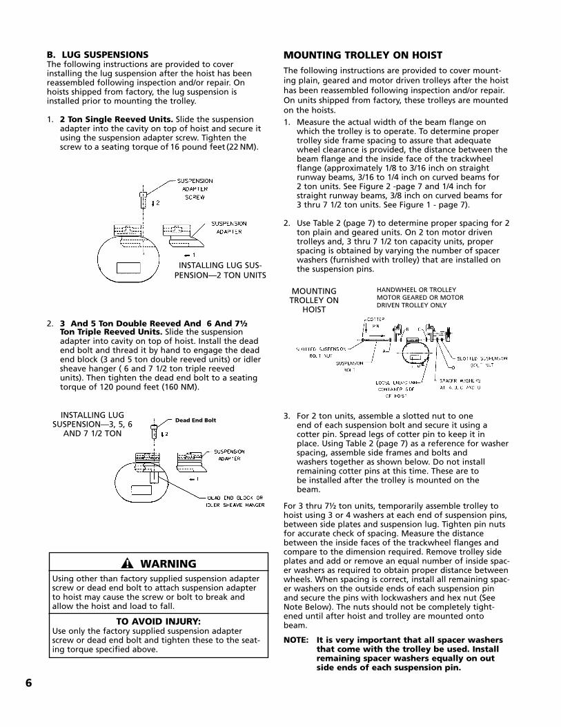
B. LUG SUSPENSIONSThe following instructions are provided to coverinstalling the lug suspension after the hoist has beenreassembled following inspection and/or repair. Onhoists shipped from factory, the lug suspension isinstalled prior to mounting the trolley.
1. 2 Ton Single Reeved Units. Slide the suspension adapter into the cavity on top of hoist and secure it using the suspension adapter screw. Tighten the screw to a seating torque of 16 pound feet (22 NM).
2. 3 And 5 Ton Double Reeved And 6 And 7½Ton Triple Reeved Units. Slide the suspensionadapter into cavity on top of hoist. Install the dead end bolt and thread it by hand to engage the dead end block (3 and 5 ton double reeved units) or idlersheave hanger ( 6 and 7 1/2 ton triple reeved units). Then tighten the dead end bolt to a seating torque of 120 pound feet (160 NM).
6
INSTALLING LUG SUS-PENSION—2 TON UNITS
INSTALLING LUGSUSPENSION—3, 5, 6AND 7 1/2 TON
MOUNTING TROLLEY ON HOISTThe following instructions are provided to cover mount-ing plain, geared and motor driven trolleys after the hoisthas been reassembled following inspection and/or repair.On units shipped from factory, these trolleys are mountedon the hoists.1. Measure the actual width of the beam flange on
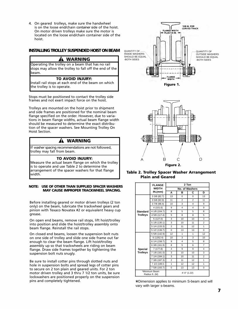
which the trolley is to operate. To determine proper trolley side frame spacing to assure that adequate wheel clearance is provided, the distance between thebeam flange and the inside face of the trackwheel flange (approximately 1/8 to 3/16 inch on straight runway beams, 3/16 to 1/4 inch on curved beams for 2 ton units. See Figure 2 -page 7 and 1/4 inch for straight runway beams, 3/8 inch on curved beams for 3 thru 7 1/2 ton units. See Figure 1 - page 7).
2. Use Table 2 (page 7) to determine proper spacing for 2ton plain and geared units. On 2 ton motor driven trolleys and, 3 thru 7 1/2 ton capacity units, proper spacing is obtained by varying the number of spacer washers (furnished with trolley) that are installed on the suspension pins.
3. For 2 ton units, assemble a slotted nut to one end of each suspension bolt and secure it using a cotter pin. Spread legs of cotter pin to keep it in place. Using Table 2 (page 7) as a reference for washerspacing, assemble side frames and bolts and washers together as shown below. Do not installremaining cotter pins at this time. These are tobe installed after the trolley is mounted on the beam.
For 3 thru 7½ ton units, temporarily assemble trolley tohoist using 3 or 4 washers at each end of suspension pins,between side plates and suspension lug. Tighten pin nutsfor accurate check of spacing. Measure the distancebetween the inside faces of the trackwheel flanges andcompare to the dimension required. Remove trolley sideplates and add or remove an equal number of inside spac-er washers as required to obtain proper distance betweenwheels. When spacing is correct, install all remaining spac-er washers on the outside ends of each suspension pinand secure the pins with lockwashers and hex nut (SeeNote Below). The nuts should not be completely tight-ened until after hoist and trolley are mounted ontobeam.
NOTE: It is very important that all spacer washers that come with the trolley be used. Install remaining spacer washers equally on outside ends of each suspension pin.
��! WARNINGUsing other than factory supplied suspension adapterscrew or dead end bolt to attach suspension adapterto hoist may cause the screw or bolt to break andallow the hoist and load to fall.
TO AVOID INJURY:Use only the factory supplied suspension adapterscrew or dead end bolt and tighten these to the seat-ing torque specified above.
MOUNTINGTROLLEY ON
HOIST
HANDWHEEL OR TROLLEY MOTOR GEARED OR MOTOR DRIVEN TROLLEY ONLY
Dead End Bolt
7
4. On geared trolleys, make sure the handwheel is on the loose end/chain container side of the hoist.On motor driven trolleys make sure the motor is located on the loose end/chain container side of thehoist.
INSTALLING TROLLEY SUSPENDED HOIST ON BEAM
Stops must be positioned to contact the trolley sideframes and not exert impact force on the hoist.
Trolleys are mounted on the hoist prior to shipmentand side frames are positioned for the nominal beamflange specified on the order. However, due to varia-tions in beam flange widths, actual beam flange widthshould be measured to determine the exact distribu-tion of the spacer washers. See Mounting Trolley OnHoist Section.
��! WARNING
TO AVOID INJURY:Install rail stops at each end of the beam on whichthe trolley is to operate.
��! WARNINGIf washer spacing recommendations are not followed,trolley may fall from beam.
TO AVOID INJURY:Measure the actual beam flange on which the trolleyis to operate and use Table 2 to determine thearrangement of the spacer washers for that flangewidth.
NOTE: USE OF OTHER THAN SUPPLIED SPACER WASHERSMAY CAUSE IMPROPER TRACKWHEEL SPACING.
Table 2. Trolley Spacer Washer Arrangement Plain and Geared
Figure 2.
Figure 1.
QUANTITY OF OUTSIDE WASHERSSHOULD BE EQUAL-BOTH SIDES
QUANTITY OF INSIDE WASHERSSHOULD BE EQUAL-BOTH SIDES
Operating the trolley on a beam that has no railstops may allow the trolley to fall off the end of thebeam.
Before installing geared or motor driven trolleys (2 tononly) on the beam, lubricate the trackwheel gears andpinion with Texaco Novatex #2 or equivalent heavy cupgrease.
On open end beams, remove rail stops, lift hoist/trolleyinto position and slide the hoist/trolley assembly ontobeam flange. Reinstall the rail stops.
On closed end beams, loosen the suspension bolt nutson one side of trolley and slide one side frame out farenough to clear the beam flange. Lift hoist/trolleyassembly up so that trackwheels are riding on beamflange. Draw side frames together by tightening thesuspension bolt nuts snugly.
Be sure to install cotter pins through slotted nuts andhole in suspension bolts and spread legs of cotter pinsto secure on 2 ton plain and geared units. For 2 tonmotor driven trolley and 3 thru 7 1/2 ton units, be surelockwashers are positioned properly on the suspensionpins and completely tightened.
*Dimension applies to minimum S-beam and willvary with larger s-beams.
8
Units with anti-tipping rollers should be adjusted to pro-vide 1/8” maximum gap between the bottom of thebeam and the roller. Run the trolley the length of thebeam to check for tight places. Readjust if needed.
On geared trolleys, the bottom of the hand chain loop isnormally located two feet (0.6M) above the floor. If it isdesired to change this, find the unwelded link and openit by spreading with a chisel or twist one end with awrench while holding the other end in a vise or anotherwrench. Remove an even number of links (2,4,6, etc.) asnecessary to shorten the chain or add an even number oflinks to lengthen the chain (when lengthening the chain,another open link will be required and this can be madefrom a welded link by cutting through weld with a hack-saw). Make certain that the chain is not twisted–then re-install and close open links.
NOTE: AFTER THE UNIT IS CONNECTED TO THE AIR SUPPLY SYSTEM (SEE BELOW), SUSPEND ACAPACITY LOAD FROM THE HOIST AND OPERATE THE TROLLEY OVER THE ENTIRE LENGTH OF THE RUNWAY OR MONORAIL SYSTEM TO BE SURE THAT THE ADJUSTMENTS AND OPERATION IS SATISFACTORY. ON SYSTEMS WITH CURVES,THE EDGES OF THE RAIL AT THE CURVED SECTIONS SHOULD BE KEPT LIGHTLY LUBRICATED WITH GREASE.
INSTALLING MUFFLERInstall the 3” long 1 1/4” NPT pipe nipple through thehole in the motor end cover and thread it into the valveexhaust port. Install the 1 1/4” NPT pipe elbow onto theend of the pipe nipple. Tighten the elbow until it facesdownward. Install the muffler into the elbow and tight-en.
�� ! WARNING An excessively worn beam flange may fail and allowthe trolley to fall from the beam.
TO AVOID INJURY:Periodically inspect the beam flange for wear. Replacebeam if flange is worn.
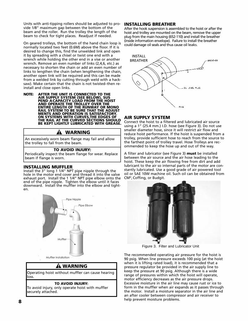
INSTALLING BREATHERAfter the hook suspension is assembled to the hoist or after thehoist and trolley are mounted on the beam, remove the upperplug from the main housing (652-110) and install the breather(inside information envelope). Failure to install the breathercould damage oil seals and thus cause oil leaks.
AIR SUPPLY SYSTEMConnect the hoist to a filtered and lubricated air sourceusing a 1” (25.4 mm.) I.D. hose (see Figure 3). Do not usesmaller diameter hose, since it will restrict air flow andreduce hoist performance. If the hoist is suspended from atrolley, provide sufficient hose to reach from the source tothe farthest point of trolley travel. Hose Trolleys are rec-ommended to keep the hose up and out of the way.
A filter and lubricator (see Figure 3) must be installedbetween the air source and the air hose leading to thehoist. These keep the air flowing free from dirt and addlubricant to the air so internal parts of the motor are con-stantly lubricated. Use a good grade of air powered tooloil or SAE 10W machine oil. Such oil can be obtained fromCM®,Coffing, or Budgit.
The recommended operating air pressure for the hoist is90 psig. When line pressure exceeds 100 psig (at the hoistwhen it is lifting rated load), it is recommended that apressure regulator be provided in the air supply line tokeep the pressure at 90 psig. Although there is a widerange of pressures within which the hoist will operate,motor efficiency decreases as the air pressure drops.Excessive moisture in the air line may cause rust or ice toform in the muffler when air expands as it passes throughthe motor. Install a moisture separator in the air line andan after cooler between compressor and air receiver tohelp prevent moisture problems.
INSTALLBREATHER
Figure 3. Filter and Lubricator Unit
�� ! WARNINGOperating hoist without muffler can cause hearingloss.
TO AVOID INJURY:To avoid injury, only operate hoist with mufflersecurely attached.
��������
�� ���
�����������
�� ���������������
OPERATING INSTRUCTIONSGENERAL1. The Protector is designed to allow the first reduction gear
to slip on an excessive overload. An overload is indicated when the hoist will not raise the load. Also, some clutchingnoise may be heard if the hoist is loaded beyond rated capacity. Should this occur, immediately release the �(Up) control to stop operation of the hoist. At this point, the load should be reduced to the rated hoist capacity or the hoist should be replaced with one of the proper capacity. When the excessive load is removed, normal hoist opera-tion is automatically restored.
CAUTION: THE PROTECTOR IS SUSCEPTIBLE TO OVERHEATING AND WEAR WHEN SLIPPED FOR EXTENDEDPERIODS. UNDER NO CIRCUMSTANCE SHOULD THEPROTECTOR BE ALLOWED TO SLIP FOR MORE THAN A FEW SECONDS.
Due to the above, a hoist equipped with a Protector is not recommended for use in any application where there is a possibility of adding to an already suspended load to the point of overload. This includes *dumbwaiter installations, containers that are loaded in mid-air, etc.
*Refer to limitations on Page ii concerning dumb-waiter applications.
Also, if a XL Hoist with a Protector is used at unusual extremes of ambient temperatures, above 150°F (65°C) or below 15° F (-9°C) changes in lubricant properties maypermit the hoist to raise larger loads than under normal operating conditions and presents possibility of damageor injury.
2. Hoist operation is controlled by depressing the pendant throttle control levers. Depressing the UP ( � )lever will move the lower hook towards the hoist and depressing the DOWN ( � ) lever will move the lower hook away from the hoist. The speed of lifting and lowering can be varied by the distance the lever is depressed. To stop lifting and lowering, release the lever. The up and down levers are momentary type and the hoist will operate in the selected direction as long as the lever is held in the depressed direction. Release the lever and the hoist will stop.
3. If material being handled must be immersed in water, pickling baths, any liquid, dusty or loose solids, use a sling chain of ample length so that the hook is always above the surface. Bearings in the hook block are shielded only against ordinary atmos-pheric conditions.
4. Read the operation section of American National Standard ASME B30.16.
ALL HOISTS1. Before picking up a load, check to see that the hoist
is directly overhead.
2. When applying a load, it should be directly under the hoist or trolley. Avoid off-center loading of any kind.
9
CHECKING FOR TWIST IN LOAD CHAIN3 And 5 Ton Double Reeved UnitsThe best way to check for this condition is to run thelower hook, without a load, to within 2 feet (0.6M) ofthe hoist. If the dead end of chain has been properlyinstalled, a twist can occur only if the lower hook blockhas been capsized between the strands of chain.Reverse capsize to remove twist.
6 And 7 1/2 Ton Triple Reeved UnitsOn these models, the load chain is dead ended on topof the lower hook block. If chain has been properlyinstalled, the only way a twist can occur is if the lowerhook block has been capsized between the strands ofchain. If this has occurred, two strands of chain will bewrapped around each other and to remove twist,reverse the capsize.
CHAIN CONTAINERIf a chain container is to be used, attach it to the hoistframe and place chain in container per instructionsprovided with the chain container kit.
UNDER NO CIRCUMSTANCES SHOULD THE HOOKBLOCK OR LOAD BE PERMITTED TO COME IN CON-TACT WITH THE CHAIN CONTAINER. IF CONTACT ISMADE, THE FUNCTION OF THE CHAIN CONTAINERCAN BE INTERFERED WITH, THE CONTAINER MAYBE DAMAGED AND IT COULD FALL OFF OF THEHOIST.
PENDANT HOSEUnless ordered on a special basis, the hoist is suppliedwith a pendant hose that will position the pendantapproximately 4 feet (1.2M) above the lower hookwhen it is at the lower limit of lift. If this places thependant too close to the floor, the pilot hoses andstrain cable can be shortened with diagonal cutters.
��! WARNING
TO AVOID INJURY:Do not allow the hook block or dead end stop tocontact the bottom of the hoist.
Allowing the hook block to run into the bottom ofthe hoist when raising a load or allowing the deadend stop to run into the frame when lowering aload may break the chain and allow the load todrop.
��! WARNING
Tying knots or loops to shorten the drop of thependant will make the strain relief ineffective andthe pilot hoses may break or collapse restricting airflow.
10
3. Take up a slack load chain carefully and start the load easily to avoid shock and jerking of the hoist load chain. If there is any evidence of overloading, immediately lower the load and remove the excess load.
4. Do not allow the load to swing or twist while hoisting.
5. Do not allow the load to bear against the hook latch.
HOIST WITH PLAIN TROLLEYThis unit should be moved by pushing on the suspended load orby pulling the empty hook.
HOIST WITH GEARED TROLLEYThis unit should be moved by means of the trolley handchain. Pull on the chain farthest from end toward whichthe unit is to travel.
HOIST WITH MOTOR DRIVEN TROLLEYThis unit should be moved by operating the controlslocated on the upper block of the pendant. Anticipatethe stopping point and allow trolley to coast to a smoothstop. Reversing or “plugging” to stop the trolley causes sway-ing of load.
SAFETY PROCEDURESFor safety precautions and a list of Do’s and Do Not’s forsafe operation of hoists, refer to page ii.
1. When preparing to lift a load, be sure that attach-ments to the hook are firmly seated in the hook sad-dle. Avoid off center loading of any kind, especially loading on the tip of the hook.
2. When lifting, raise load only enough to clear the floor or support and check to be sure that the attachments to the hook and load are firmly seated. Continue lift only after you are assured the load is free of all obstructions.
3. Do not load hoist beyond the rated load shown on hoist identification plate and capacity labels.Overload can cause immediate failure of some load-carrying part or create a defect causing subsequent failure at less than rated load. When in doubt, use the next larger capacity of XL Hoist.
4. Do not use this or any other overhead materials han-dling equipment for lifting persons.
5. Stand clear of all loads and avoid moving a load over the heads of other personnel. Warn personnel of your intention to move a load in their area.
6. Do not leave load suspended in air unattended.
7. Permit only qualified personnel to operate unit.
8. Do not wrap the load chain around the load and hook onto itself as a choker chain.Doing this will result in:a. The loss of the swivel effect of the hook which
could mean twisted chain and a jammed liftwheel.
b. The chain could be damaged at the hook.
9. On double and triple reeved hoists, check for twists in the load chain. A twist can occur if the lower
hook block has been capsized between the strands of chain. Reverse the capsize to remove the twist.
10. Do not allow the load to bear against the hook latch. The latch is to help maintain the hook in posi-tion while the chain is slack before taking up slack chain.
11. Take up a slack load chain carefully and start load eas-ily to avoid shock and jerking of hoist load chain. If there is any evidence of overloading, immediately lower the load and remove the excess load.
12. Do not allow the load to swing or twist while hoisting.
13. STAY ALERT! Watch what you are doing and use common sense. Do not use the hoist when you are tired, distracted or under the influence of drugs, alcohol or medication causing diminished control.
INSPECTION
To maintain continuous and satisfactory operation, a reg-ular inspection procedure must be initiated to replaceworn or damaged parts before they become unsafe.Inspection intervals must be determined by the individ-ual application and are based on the type of service towhich the hoist will be subjected and degree of exposureto wear, deterioration or malfunction of the critical com-ponents.
The type of service to which the hoist is subjected can beclassified as “Normal,” “Heavy,” or “Severe.”
Normal Service: Involves operation with randomly distrib-uted loads within rated load limit, or uniform loads lessthan 65 percent of rated load for not more than 25 per-cent of the time.
Heavy Service: Involves operating the hoist within ratedload limit which exceeds normal service.
Severe Service: Normal or heavy service with abnormaloperating conditions.
Two classes of inspection—Frequent and Periodic—must be performed.
FREQUENT INSPECTIONS: These inspections are visualexaminations by the operator or other designated person-nel. Records of such inspections are not required. The fre-quent inspections are to be performed monthly for normalservice, weekly to monthly for heavy service, and daily toweekly for severe service, and they should include thoseitems listed in Table 3.
PERIODIC INSPECTIONS: These inspections are visualinspections of external conditions by an appointed person.
�� ! WARNINGAllowing the load to bear against the hook latchand/or hook tip can result in loss of load.
TO AVOID INJURY:Do not allow the load to bear against the hook latchand/or hook tip. Apply load to hook bowl or saddle only.
MAINTENANCE
Replace HookWhen OpeningIs GreaterThan
1 1/2 IN.38.1 mm
2 3/8 IN.60.3 mm
CAPACITY(TONS)
2
3, 5, 6 AND 7 ½
LATCH TYPE HOOK(Upper and Lower)TO MEASURE OPENING,DEPRESS LATCH AGAINSTHOOK BODY AS SHOWN.
*UPPER HOOK NOT AVAIL ABLEFOR 7 1/2 TON
Replace HookWhen OpeningOr Seat are:
CAPACITY(TONS)
2
3, 5, and 6
LATCHLOCK® TYPE HOOK(UPPER AND LOWER)
“A” Max.2 1/2 IN.63.5 mm
2 15/16 IN.74.6 mm
“B” Mn.1 1/8 IN.28.5mm
1 13/32 IN.35.7mm
Hook Inspection
MEASURE
OPENING
“A”
“B” Max.
LOAD CHAIN
Cleaning and InspectionFirst clean the load chain with a non-acid or non-caustictype solvent. Then slack the chain and make a link-by-link inspection for nicks, gouges, twisted links and exces-sive wear or stretching. Chain exhibiting wear should bechecked throughout its entire length and replaced ifworn beyond serviceable limits.
Checking For Load Chain WearSlack the portion of the chain that normally passes overthe liftwheel. Examine the interlink area for the point ofmaximum wear (polishing). Measure and record the stockdiameter at this point of the link. Then measure stockdiameter in the same area on a link that does not passover the liftwheel (use the link adjacent to the loose endlink for this purpose). Compare these two measurements.If the stock diameter of the worn link is 0.010 inches(0.254mm), or greater, less than the stock diameter ofthe unworn link, the chain must be replaced.
Note that worn chain can be an indication of worn hoistcomponents. For this reason, the hoist’s chain guides,hook blocks and liftwheel should be examined for wearand replaced as necessary when replacing worn chain.
Also, these chains are specially heat treated and hard-ened and should never be repaired.
��! WARNINGUsing other than factory supplied load chain maycause the chain to jam in the hoist and/or allow thechain to break and the load to drop.
TO AVOID INJURY:Due to size requirements and physical properties, useonly Hoistaloy® load chain in the XL Air Hoists.
IMPORTANT:DO NOT USE REPLACED CHAIN FOR OTHER PURPOS-ES SUCH AS LIFTING OR PULLING. LOAD CHAIN MAYBREAK SUDDENLY WITHOUT VISUAL DEFORMATION.FOR THIS REASON, CUT REPLACED CHAIN INTOSHORT LENGTHS TO PREVENT USE AFTER DISPOSAL.
PROTECTOR™The Protector should operate for the normal life ofhoist without service. The device has been calibratedat the factory for a specific capacity/gear ratio of theXL Air Hoist. It is not adjustable and it is not inter-changeable with other capacities/gear ratios. RATED LOAD *LIFT SPEED COLOR CODETONS (Kg.) FPM (MPM)
Records of periodic inspections are to be kept for continuingevaluation of the condition of the hoist. Periodic inspectionsare to be performed yearly for normal service, semi-annuallyfor heavy service and quarterly for severe service, and theyare to include those items listed in Table 3.
CAUTION: ANY DEFICIENCIES ARE TO BE CORRECTED BEFORE THE HOIST IS RETURNED TO SERVICE. ALSO,THE EXTERNAL CONDITIONS MAY SHOW THE NEEDFOR DISASSEMBLY TO PERMIT A MORE DETAILEDINSPECTION, WHICH, IN TURN, MAY REQUIRE THE USEOF NONDESTRUCTIVE TYPE TESTING.
HOOK INSPECTIONHooks damaged from chemicals, deformations or cracks, orthat have more than a 10° twist from the hook’s unbentplane, excessive opening or seat wear must be replaced. Also,hooks that are opened and allow the latch to not engage thetip must be replaced. Any hook that is twisted or has exces-sive throat opening indicates abuse or overloading of theunit. Inspect other load sustaining parts for damage.
On latch type hooks, check to make sure that the latch is notdamaged or bent and that it operates properly with sufficientspring pressure to keep the latch tightly against the tip of thehook and allow latch to spring back to tip when released. Iflatch does not operate properly, it should be replaced. Seebelow to determine when the hook must be replaced.
12
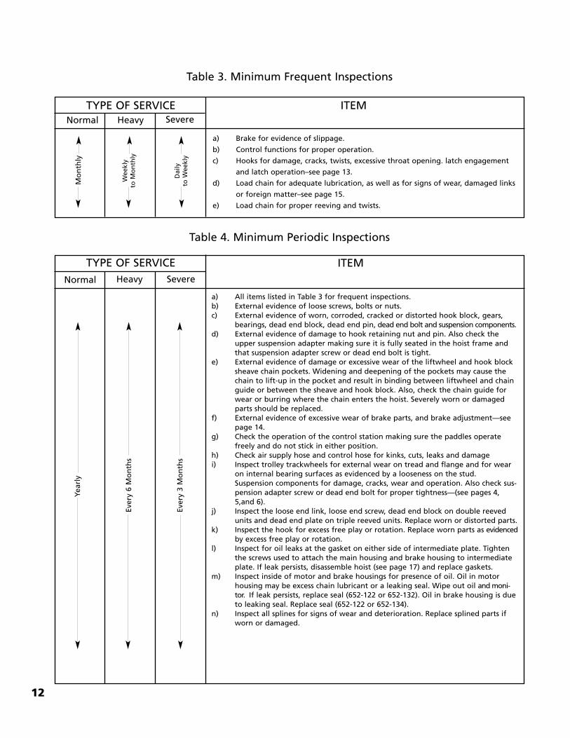
Table 3. Minimum Frequent Inspections
TYPE OF SERVICE ITEMNormal Heavy Severe
a) Brake for evidence of slippage.
b) Control functions for proper operation.
c) Hooks for damage, cracks, twists, excessive throat opening. latch engagement
and latch operation–see page 13.
d) Load chain for adequate lubrication, as well as for signs of wear, damaged links
or foreign matter–see page 15.
e) Load chain for proper reeving and twists.
Daily
to Weekly
Weekly
to Monthly
Monthly
Table 4. Minimum Periodic Inspections
ITEMNormal Heavy Severe
TYPE OF SERVICE
a) All items listed in Table 3 for frequent inspections.b) External evidence of loose screws, bolts or nuts.c) External evidence of worn, corroded, cracked or distorted hook block, gears,
bearings, dead end block, dead end pin, dead end bolt and suspension components.d) External evidence of damage to hook retaining nut and pin. Also check the
upper suspension adapter making sure it is fully seated in the hoist frame andthat suspension adapter screw or dead end bolt is tight.
e) External evidence of damage or excessive wear of the liftwheel and hook blocksheave chain pockets. Widening and deepening of the pockets may cause thechain to lift-up in the pocket and result in binding between liftwheel and chainguide or between the sheave and hook block. Also, check the chain guide forwear or burring where the chain enters the hoist. Severely worn or damagedparts should be replaced.
f) External evidence of excessive wear of brake parts, and brake adjustment—seepage 14.
g) Check the operation of the control station making sure the paddles operatefreely and do not stick in either position.
h) Check air supply hose and control hose for kinks, cuts, leaks and damagei) Inspect trolley trackwheels for external wear on tread and flange and for wear
on internal bearing surfaces as evidenced by a looseness on the stud.Suspension components for damage, cracks, wear and operation. Also check sus-pension adapter screw or dead end bolt for proper tightness—(see pages 4,5,and 6).
j) Inspect the loose end link, loose end screw, dead end block on double reevedunits and dead end plate on triple reeved units. Replace worn or distorted parts.
k) Inspect the hook for excess free play or rotation. Replace worn parts as evidencedby excess free play or rotation.
l) Inspect for oil leaks at the gasket on either side of intermediate plate. Tightenthe screws used to attach the main housing and brake housing to intermediateplate. If leak persists, disassemble hoist (see page 17) and replace gaskets.
m) Inspect inside of motor and brake housings for presence of oil. Oil in motorhousing may be excess chain lubricant or a leaking seal. Wipe out oil and moni-tor. If leak persists, replace seal (652-122 or 652-132). Oil in brake housing is dueto leaking seal. Replace seal (652-122 or 652-134).
n) Inspect all splines for signs of wear and deterioration. Replace splined parts ifworn or damaged.
Yearly
Every 6 Months
Every 3 Months
13
Notes
14
LUBRICATION
NOTE: TO ASSURE LONG LIFE AND TOP PERFORMANCE, BE SURE TO LUBRICATE THE VARIOUS PARTS OF THE XL AIR HOIST USING THE LUBRICANTSSPECIFIED BELOW. IF DESIRED, THESE LUBRCANTS MAY BE PURCHASED FROM THE FACTORY.
HOIST LUBRICATIONGears. Check the oil level in gear housing at least once amonth, maintaining it at the bottom of oil level hole inthe main housing (652-110).
Drain the housing every 2-3 years and refill with one gal-lon (3.86 liters) of gear oil Hulbest EP ISO VG 68 thru 460(H-2 Classification).
CAUTION: THE PROTECTOR IS DESIGNED TO OPERATE IN THE ABOVE MENTIONED OIL. DO NOT USE ANY OTHER TYPE OF LUBRICANT OR THE PROTECTOR WILL NOT OPERATE PROPERLY AND PARTS COULD BE DAMAGED.
Chain Guides, Liftwheel & Sheave Wheels.When the hoist is disassembled for inspection and/orrepair, the chain guides, sheave wheels (on multi-reevedunits) and liftwheel must be lubricated with Lubriplate Barand Chain Oil 10-R (Fiske Bros. Refining Co.) prior toreassembly. Apply sufficient lubricant to obtain naturalrunoff and full coverage.
Load Chain. Keep chain lubricated with a small amountof lubricant. This will greatly increase the life of loadchain. Do not allow the chain to run dry.
Keep it clean and lubricate at regular intervals withLubriplate Bar and Chain Oil 10-R (Fiske Bros. Refining Co.) or equal lubricant. Normally, weekly lubrication andcleaning is satisfactory, but under hot and dirty conditions,it may be necessary to clean the chain at least once a dayand lubricate it several times between cleanings. Whenlubricating the chain, apply sufficient lubricant to obtainnatural runoff and full coverage.
Bearings. All bearings except the lower hook thrust bear-ings are pre-lubricated or are in an oil bath and need nolubrication. The lower hook thrust bearing should be lubri-cated at least once a month with heavy duty machine oil.
��! WARNINGThe lubricants used in and recommended for the XL Air Hoistmay contain hazardous materials that mandate specific han-dling and disposal procedures.
TO AVOID CONTACT AND CONTAMINATION:Handle and dispose of lubricants only as directed in applicablematerial safety data sheets and in accordance with applicablelocal, state and federal regulations.
��! WARNINGUsed motor oils contain known carcinogenic materials.
TO AVOID HEALTH PROBLEMS:Never use used motor oils as a chain lubricant. Onlyuse Lubriplate Bar and Chain Oil 10-R or equal as alubricant for the load chain.
Service Air Line Lubricator. The air line filter andlubricator is the only source of lubrication for controlvalves and air motor. Fill lubricator with a good gradeair tool oil or 10W machine oil Feed one drop of oil forevery 50 to 75 cubic feet of air going through the airmotor.
Miscellaneous. If the unit is disassembled, splinesinside the coupling (652-103) should be coated with anEP type grease (such as Evans Products Co. Anti-ScoringExtreme Pressure Lub. No. 3) before reassembly.
TROLLEY LUBRICATIONTrackwheel bearings are pre-lubricated and require nolubrication.
Geared Trolley. Once a month lubricate trackwheelgears with Texaco Novatex No. 2 or an equivalent heavycup grease or graphite grease.
Every six months lubricate handwheel shaft bearings in 3-in-1 machine oil.
Motor Driven Trolley. Once a month lubricate track-wheel gears with Texaco Novatex No. 2 or an equivalentheavy cup grease or graphite grease.
For 2-7 1/2 ton trolleys, the right angle worm gear reducer oilshould be changed after the first 100 hours of operation, thenafter every 2500 hours of normal service. When replacing oildue to repairs or service, use Mobil SHC-626 or equal, foreach oil change.
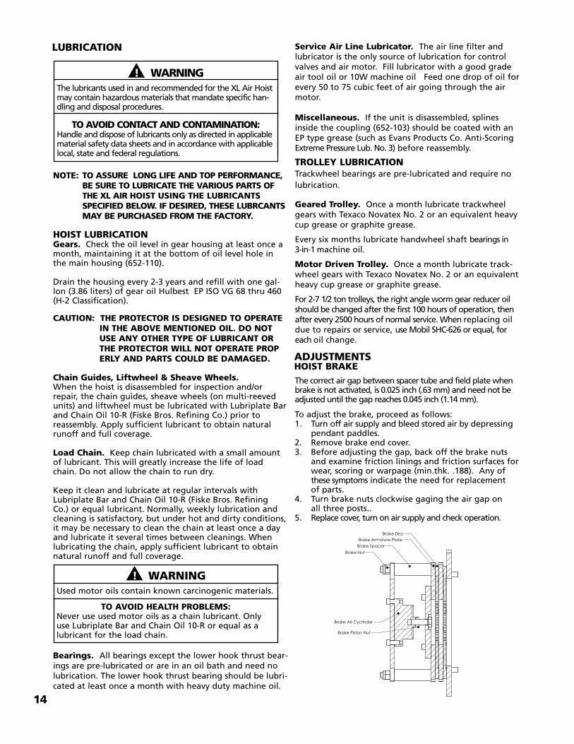
ADJUSTMENTSHOIST BRAKEThe correct air gap between spacer tube and field plate whenbrake is not activated, is 0.025 inch (.63 mm) and need not beadjusted until the gap reaches 0.045 inch (1.14 mm).
To adjust the brake, proceed as follows:1. Turn off air supply and bleed stored air by depressing
pendant paddles.2. Remove brake end cover.3. Before adjusting the gap, back off the brake nuts
and examine friction linings and friction surfaces forwear, scoring or warpage (min.thk. .188). Any of these symptoms indicate the need for replacement of parts.
4. Turn brake nuts clockwise gaging the air gap onall three posts..
5. Replace cover, turn on air supply and check operation.
�����������������
������ ������������
����������
�������������������
������������
15
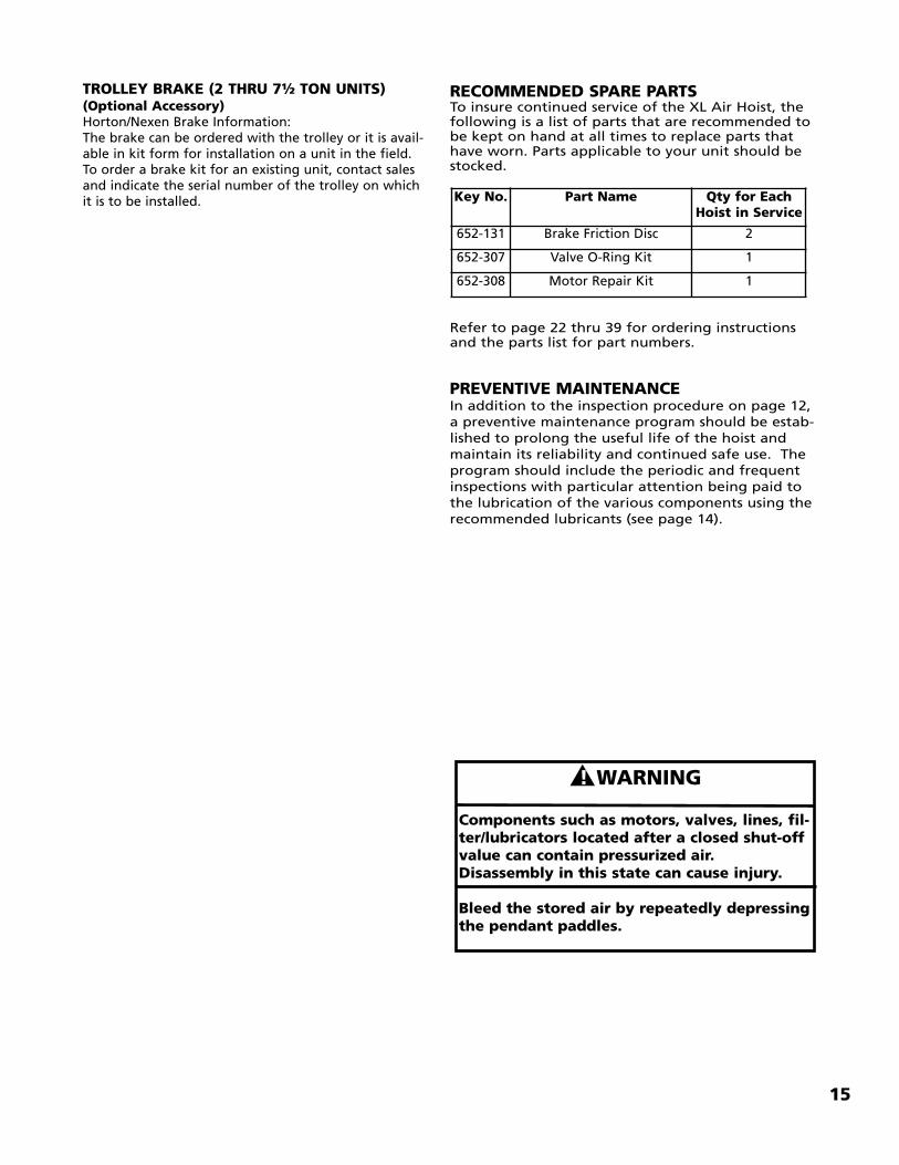
RECOMMENDED SPARE PARTSTo insure continued service of the XL Air Hoist, the following is a list of parts that are recommended tobe kept on hand at all times to replace parts thathave worn. Parts applicable to your unit should bestocked.
Refer to page 22 thru 39 for ordering instructionsand the parts list for part numbers.
PREVENTIVE MAINTENANCEIn addition to the inspection procedure on page 12,a preventive maintenance program should be estab-lished to prolong the useful life of the hoist andmaintain its reliability and continued safe use. Theprogram should include the periodic and frequentinspections with particular attention being paid tothe lubrication of the various components using therecommended lubricants (see page 14).
Key No. Part Name Qty for EachHoist in Service
652-131 Brake Friction Disc 2
652-307 Valve O-Ring Kit 1
652-308 Motor Repair Kit 1
TROLLEY BRAKE (2 THRU 7½ TON UNITS)(Optional Accessory)Horton/Nexen Brake Information:The brake can be ordered with the trolley or it is avail-able in kit form for installation on a unit in the field.To order a brake kit for an existing unit, contact salesand indicate the serial number of the trolley on whichit is to be installed.
� ! WARNING
Components such as motors, valves, lines, fil-ter/lubricators located after a closed shut-offvalue can contain pressurized air.Disassembly in this state can cause injury.
Bleed the stored air by repeatedly depressingthe pendant paddles.
16
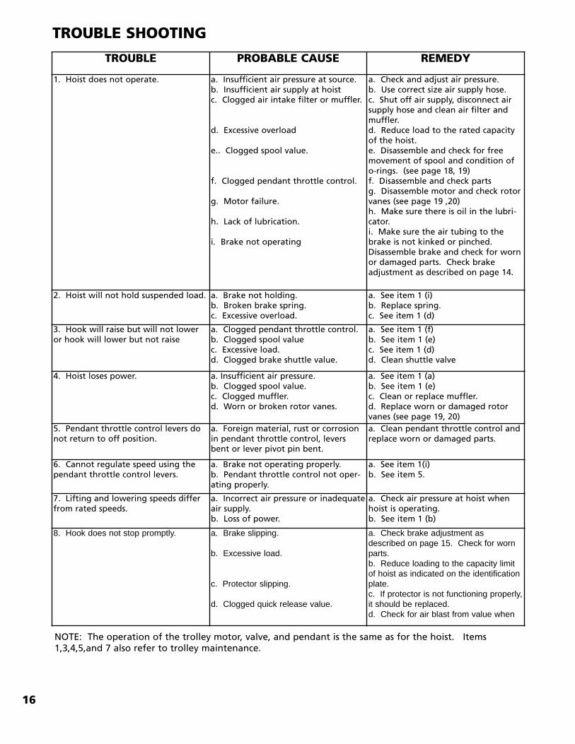
TROUBLE SHOOTING
TROUBLE PROBABLE CAUSE REMEDY
1. Hoist does not operate. a. Insufficient air pressure at source.b. Insufficient air supply at hoistc. Clogged air intake filter or muffler.
d. Excessive overload
e.. Clogged spool value.
f. Clogged pendant throttle control.
g. Motor failure.
h. Lack of lubrication.
i. Brake not operating
a. Check and adjust air pressure.b. Use correct size air supply hose.c. Shut off air supply, disconnect airsupply hose and clean air filter andmuffler.d. Reduce load to the rated capacityof the hoist.e. Disassemble and check for freemovement of spool and condition ofo-rings. (see page 18, 19)f. Disassemble and check parts g. Disassemble motor and check rotorvanes (see page 19 ,20)h. Make sure there is oil in the lubri-cator.i. Make sure the air tubing to thebrake is not kinked or pinched.Disassemble brake and check for wornor damaged parts. Check brakeadjustment as described on page 14.
2. Hoist will not hold suspended load. a. Brake not holding.b. Broken brake spring.c. Excessive overload.
a. See item 1 (i)b. Replace spring.c. See item 1 (d)
3. Hook will raise but will not loweror hook will lower but not raise
a. Clogged pendant throttle control.b. Clogged spool valuec. Excessive load.d. Clogged brake shuttle value.
a. See item 1 (f)b. See item 1 (e)c. See item 1 (d)d. Clean shuttle valve
4. Hoist loses power. a. Insufficient air pressure.b. Clogged spool value.c. Clogged muffler.d. Worn or broken rotor vanes.
a. See item 1 (a)b. See item 1 (e)c. Clean or replace muffler.d. Replace worn or damaged rotorvanes (see page 19, 20)
5. Pendant throttle control levers donot return to off position.
a. Foreign material, rust or corrosionin pendant throttle control, leversbent or lever pivot pin bent.
a. Clean pendant throttle control andreplace worn or damaged parts.
6. Cannot regulate speed using thependant throttle control levers.
a. Brake not operating properly.b. Pendant throttle control not oper-ating properly.
a. See item 1(i)b. See item 5.
7. Lifting and lowering speeds differfrom rated speeds.
a. Incorrect air pressure or inadequateair supply.b. Loss of power.
a. Check air pressure at hoist whenhoist is operating.b. See item 1 (b)
8. Hook does not stop promptly. a. Brake slipping.
b. Excessive load.
c. Protector slipping.
d. Clogged quick release value.
a. Check brake adjustment asdescribed on page 15. Check for wornparts.b. Reduce loading to the capacity limitof hoist as indicated on the identificationplate.c. If protector is not functioning properly,it should be replaced.d. Check for air blast from value when
NOTE: The operation of the trolley motor, valve, and pendant is the same as for the hoist. Items1,3,4,5,and 7 also refer to trolley maintenance.
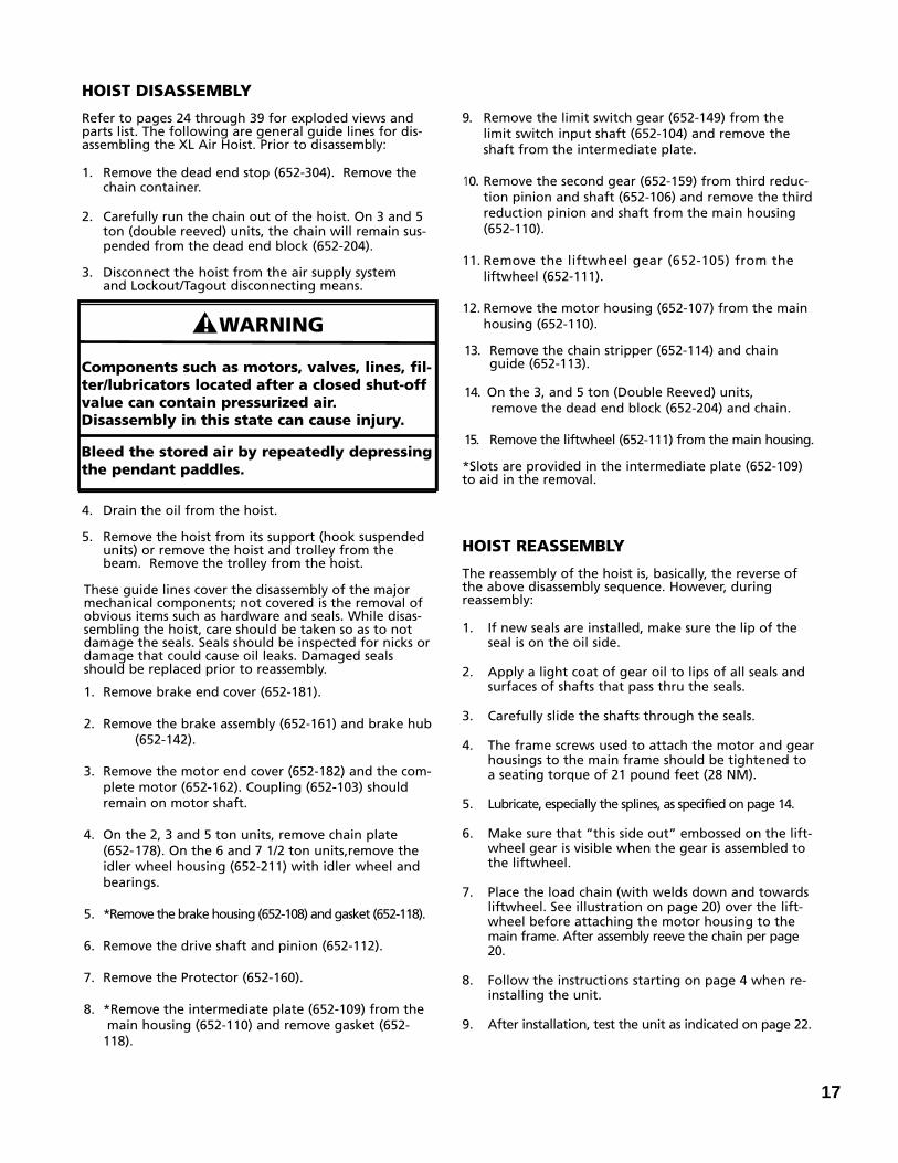
HOIST DISASSEMBLY
Refer to pages 24 through 39 for exploded views andparts list. The following are general guide lines for dis-assembling the XL Air Hoist. Prior to disassembly:
1. Remove the dead end stop (652-304). Remove the chain container.
2. Carefully run the chain out of the hoist. On 3 and 5 ton (double reeved) units, the chain will remain sus-pended from the dead end block (652-204).
3. Disconnect the hoist from the air supply system and Lockout/Tagout disconnecting means.
4. Drain the oil from the hoist.
5. Remove the hoist from its support (hook suspended units) or remove the hoist and trolley from the beam. Remove the trolley from the hoist.
These guide lines cover the disassembly of the majormechanical components; not covered is the removal ofobvious items such as hardware and seals. While disas-sembling the hoist, care should be taken so as to notdamage the seals. Seals should be inspected for nicks ordamage that could cause oil leaks. Damaged sealsshould be replaced prior to reassembly.
1. Remove brake end cover (652-181).
2. Remove the brake assembly (652-161) and brake hub(652-142).
3. Remove the motor end cover (652-182) and the com-plete motor (652-162). Coupling (652-103) should remain on motor shaft.
4. On the 2, 3 and 5 ton units, remove chain plate (652-178). On the 6 and 7 1/2 ton units,remove the idler wheel housing (652-211) with idler wheel and bearings.
5. *Remove the brake housing (652-108) and gasket (652-118).
6. Remove the drive shaft and pinion (652-112).
7. Remove the Protector (652-160).
8. *Remove the intermediate plate (652-109) from themain housing (652-110) and remove gasket (652-118).
9. Remove the limit switch gear (652-149) from the limit switch input shaft (652-104) and remove the shaft from the intermediate plate.
10. Remove the second gear (652-159) from third reduc-tion pinion and shaft (652-106) and remove the thirdreduction pinion and shaft from the main housing (652-110).
11. Remove the liftwheel gear (652-105) from the liftwheel (652-111).
12. Remove the motor housing (652-107) from the main housing (652-110).
13. Remove the chain stripper (652-114) and chain guide (652-113).
14. On the 3, and 5 ton (Double Reeved) units, remove the dead end block (652-204) and chain.
15. Remove the liftwheel (652-111) from the main housing.
*Slots are provided in the intermediate plate (652-109)to aid in the removal.
HOIST REASSEMBLY
The reassembly of the hoist is, basically, the reverse ofthe above disassembly sequence. However, duringreassembly:
1. If new seals are installed, make sure the lip of the seal is on the oil side.
2. Apply a light coat of gear oil to lips of all seals and surfaces of shafts that pass thru the seals.
3. Carefully slide the shafts through the seals.
4. The frame screws used to attach the motor and gearhousings to the main frame should be tightened to a seating torque of 21 pound feet (28 NM).
5. Lubricate, especially the splines, as specified on page 14.
6. Make sure that “this side out” embossed on the lift-wheel gear is visible when the gear is assembled to the liftwheel.
7. Place the load chain (with welds down and towards liftwheel. See illustration on page 20) over the lift-wheel before attaching the motor housing to the main frame. After assembly reeve the chain per page 20.
8. Follow the instructions starting on page 4 when re-installing the unit.
9. After installation, test the unit as indicated on page 22.
17
� ! WARNING
Components such as motors, valves, lines, fil-ter/lubricators located after a closed shut-offvalue can contain pressurized air.Disassembly in this state can cause injury.
Bleed the stored air by repeatedly depressingthe pendant paddles.
18
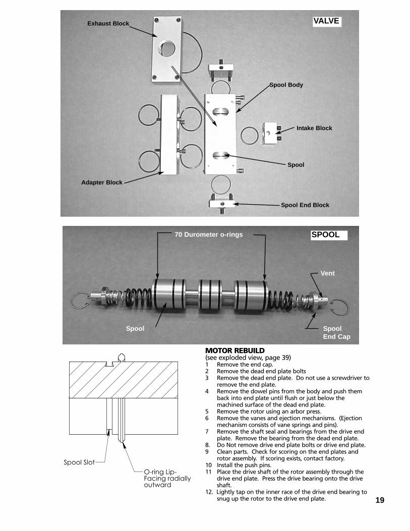
VALVE DISASSEMBLY
1. Turn off the air supply and bleed off the stored air by repeatedly depressing the pendant paddles.
2. Disconnect the five air lines (3/16” dia.) by pushing the plastic collars toward the body of the quick connect fit-tings and pulling on the 3/16” diameter tube.
3. Remove the (4) attaching bolts for the spool body.
4. Remove the (4) attaching bolts for the adapter block.
5. Remove the intake, exhaust, and spool end block by removing the (4) socket head cap screws in each block.Remove and discard the o-rings from under each block.
6. Push the spool out of the spool body. Pull the (9) o-rings radially from the slots of the spool using a sharp dental pick. DO NOT PRY AGAINST THE EDGE OF THE SLOTS. Narrow faced diagonal cutters can be used to cut the o-ring to aid in removal but do not contact the edge of the slots.
7. Remove the spool end caps using an arbor press and snap ring pliers with right angle tips. CAUTION: The end caps are under spring tension, therefore pressure from the arbor press must be applied when removing the retaining rings.
8. Clean all parts in a mild solvent or detergent. Examine the O.D. of the spool and the I.D. of the spool body. If these surfaces have been scored by debris, the value should be replaced because the o-ring will not seal against a gouged surface.
VALVE REASSEMBLY1. Lubricate the return end caps, springs, and spool cavity
with a layer of EP grease as listed on page 14. Be sure the vents on the end caps are exposed. Compress the springs and caps with an arbor press and install the retaining ring.
2. Install the new spool o-rings from kit 653-307. Start from either end and work inward. Apply a coating of 10W machine oil to the spool and slots for easier assem-bly. The 70 durometer (softer) o-rings are inserted into the two end slots.The 90 durometer (harder) o-rings are inserted into slots 2 thru 8. These slots are narrower at the top for reten-tion of the o-rings and require special assembly. An o-ring has a flash line or lip at the I.D. and O.D. Roll an o-ring adjacent to the slot and align the outer lip. If the o-ring is twisted it will cause the spool to stick in the body and give less slow speed control. Grab the o-ring on opposite sides of the spool and slide into the slot. Roll the spool on a clean hard surface to push the o-ring into the slot. Again; oil the spool assembly and bore of the spool body and assemble components.
3. Insert new o-rings under the various blocks and assembleto the spool body, motor, and adapter block. Tighten the screws to 90 in-lbs. torque.
4. Reassemble the (5) control lines as shown in the picture.
Down PilotTube (Blue)
Up PilotTube (Red)
Spool Body
Spool BodyScrews
Quick ConnectFitting Collar
Quick Exhaust ValveAdapter Block
Motor End View
19
��������������� ��������������������
MOTOR REBUILD(see exploded view, page 39)1 Remove the end cap.2 Remove the dead end plate bolts3 Remove the dead end plate. Do not use a screwdriver to
remove the end plate.4 Remove the dowel pins from the body and push them
back into end plate until flush or just below the machined surface of the dead end plate.
5 Remove the rotor using an arbor press.6 Remove the vanes and ejection mechanisms. (Ejection
mechanism consists of vane springs and pins).7 Remove the shaft seal and bearings from the drive end
plate. Remove the bearing from the dead end plate.8. Do Not remove drive end plate bolts or drive end plate.9 Clean parts. Check for scoring on the end plates and
rotor assembly. If scoring exists, contact factory.10 Install the push pins.11 Place the drive shaft of the rotor assembly through the
drive end plate. Press the drive bearing onto the drive shaft.
12. Lightly tap on the inner race of the drive end bearing to snug up the rotor to the drive end plate.
Exhaust Block
Adapter Block
Spool Body
Intake Block
Spool
Spool End Block
Spool Spool End Cap
Vent
70 Durometer o-rings
VALVE
SPOOL
20
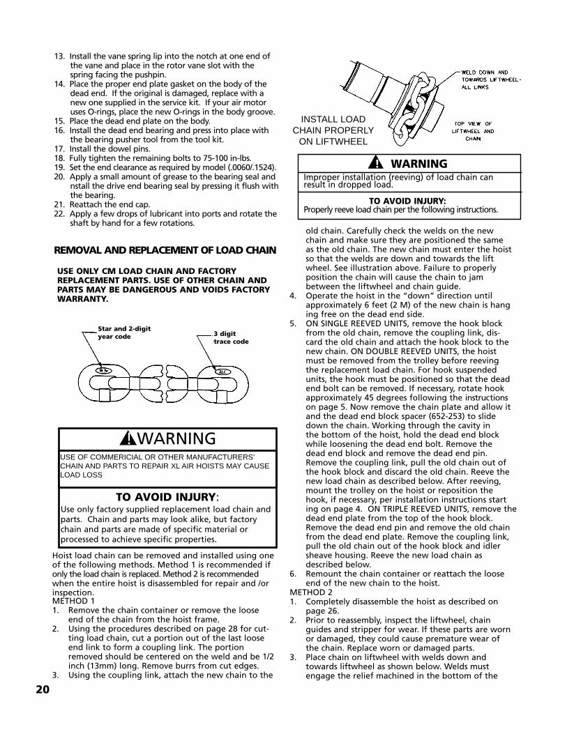
INSTALL LOADCHAIN PROPERLYON LIFTWHEEL
��! WARNINGImproper installation (reeving) of load chain can result in dropped load.
TO AVOID INJURY:Properly reeve load chain per the following instructions.
USE ONLY CM LOAD CHAIN AND FACTORYREPLACEMENT PARTS. USE OF OTHER CHAIN ANDPARTS MAY BE DANGEROUS AND VOIDS FACTORYWARRANTY.
Star and 2-digityear code
�! WARNING
TO AVOID INJURY:Use only factory supplied replacement load chain andparts. Chain and parts may look alike, but factorychain and parts are made of specific material orprocessed to achieve specific properties.
USE OF COMMERICIAL OR OTHER MANUFACTURERS’CHAIN AND PARTS TO REPAIR XL AIR HOISTS MAY CAUSELOAD LOSS
13. Install the vane spring lip into the notch at one end of the vane and place in the rotor vane slot with the spring facing the pushpin.
14. Place the proper end plate gasket on the body of the dead end. If the original is damaged, replace with a new one supplied in the service kit. If your air motor uses O-rings, place the new O-rings in the body groove.
15. Place the dead end plate on the body.16. Install the dead end bearing and press into place with
the bearing pusher tool from the tool kit.17. Install the dowel pins.18. Fully tighten the remaining bolts to 75-100 in-lbs.19. Set the end clearance as required by model (.0060/.1524).20. Apply a small amount of grease to the bearing seal and
nstall the drive end bearing seal by pressing it flush withthe bearing.
21. Reattach the end cap.22. Apply a few drops of lubricant into ports and rotate the
shaft by hand for a few rotations.
REMOVAL AND REPLACEMENT OF LOAD CHAIN
Hoist load chain can be removed and installed using oneof the following methods. Method 1 is recommended ifonly the load chain is replaced. Method 2 is recommended when the entire hoist is disassembled for repair and /orinspection.METHOD 11. Remove the chain container or remove the loose
end of the chain from the hoist frame.2. Using the procedures described on page 28 for cut-
ting load chain, cut a portion out of the last loose end link to form a coupling link. The portion removed should be centered on the weld and be 1/2 inch (13mm) long. Remove burrs from cut edges.
3. Using the coupling link, attach the new chain to the
old chain. Carefully check the welds on the new chain and make sure they are positioned the same as the old chain. The new chain must enter the hoist so that the welds are down and towards the liftwheel. See illustration above. Failure to properly position the chain will cause the chain to jam between the liftwheel and chain guide.
4. Operate the hoist in the “down” direction until approximately 6 feet (2 M) of the new chain is hanging free on the dead end side.
5. ON SINGLE REEVED UNITS, remove the hook block from the old chain, remove the coupling link, dis-card the old chain and attach the hook block to the new chain. ON DOUBLE REEVED UNITS, the hoist must be removed from the trolley before reeving the replacement load chain. For hook suspended units, the hook must be positioned so that the dead end bolt can be removed. If necessary, rotate hook approximately 45 degrees following the instructionson page 5. Now remove the chain plate and allow it and the dead end block spacer (652-253) to slide down the chain. Working through the cavity in the bottom of the hoist, hold the dead end block while loosening the dead end bolt. Remove the dead end block and remove the dead end pin.Remove the coupling link, pull the old chain out of the hook block and discard the old chain. Reeve the new load chain as described below. After reeving, mount the trolley on the hoist or reposition the hook, if necessary, per installation instructions starting on page 4. ON TRIPLE REEVED UNITS, remove thedead end plate from the top of the hook block. Remove the dead end pin and remove the old chain from the dead end plate. Remove the coupling link, pull the old chain out of the hook block and idler sheave housing. Reeve the new load chain as described below.
6. Remount the chain container or reattach the loose end of the new chain to the hoist.
METHOD 21. Completely disassemble the hoist as described on
page 26.2. Prior to reassembly, inspect the liftwheel, chain
guides and stripper for wear. If these parts are worn or damaged, they could cause premature wear of the chain. Replace worn or damaged parts.
3. Place chain on liftwheel with welds down and towards liftwheel as shown below. Welds must engage the relief machined in the bottom of the
3 digittrace code
21
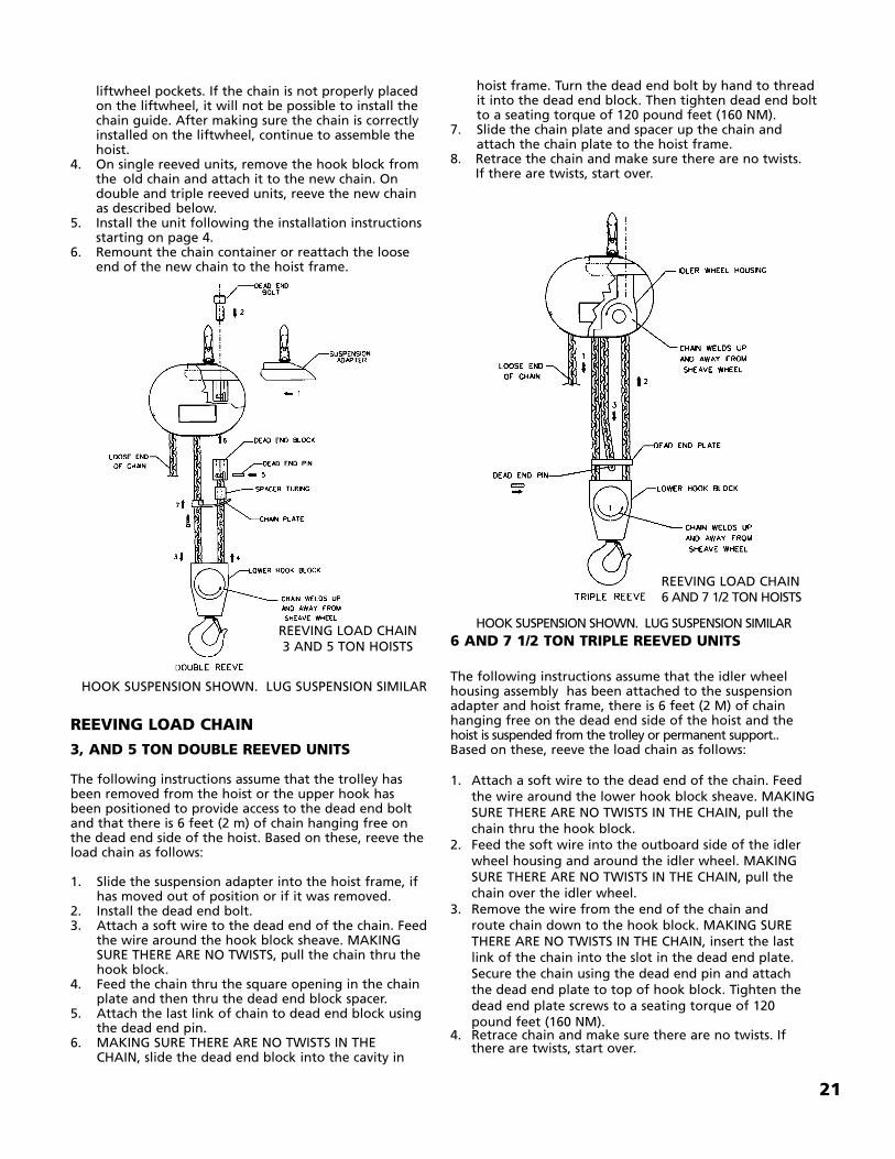
hoist frame. Turn the dead end bolt by hand to thread it into the dead end block. Then tighten dead end boltto a seating torque of 120 pound feet (160 NM).
7. Slide the chain plate and spacer up the chain and attach the chain plate to the hoist frame.
8. Retrace the chain and make sure there are no twists.If there are twists, start over.
6 AND 7 1/2 TON TRIPLE REEVED UNITS
The following instructions assume that the idler wheelhousing assembly has been attached to the suspensionadapter and hoist frame, there is 6 feet (2 M) of chainhanging free on the dead end side of the hoist and thehoist is suspended from the trolley or permanent support..Based on these, reeve the load chain as follows:
1. Attach a soft wire to the dead end of the chain. Feed the wire around the lower hook block sheave. MAKING SURE THERE ARE NO TWISTS IN THE CHAIN, pull the chain thru the hook block.
2. Feed the soft wire into the outboard side of the idler wheel housing and around the idler wheel. MAKING SURE THERE ARE NO TWISTS IN THE CHAIN, pull the chain over the idler wheel.
3. Remove the wire from the end of the chain and route chain down to the hook block. MAKING SURE THERE ARE NO TWISTS IN THE CHAIN, insert the last link of the chain into the slot in the dead end plate. Secure the chain using the dead end pin and attach the dead end plate to top of hook block. Tighten the dead end plate screws to a seating torque of 120 pound feet (160 NM).
4. Retrace chain and make sure there are no twists. If there are twists, start over.
liftwheel pockets. If the chain is not properly placed on the liftwheel, it will not be possible to install the chain guide. After making sure the chain is correctly installed on the liftwheel, continue to assemble the hoist.
4. On single reeved units, remove the hook block from the old chain and attach it to the new chain. On double and triple reeved units, reeve the new chain as described below.
5. Install the unit following the installation instructions starting on page 4.
6. Remount the chain container or reattach the loose end of the new chain to the hoist frame.
REEVING LOAD CHAIN
3, AND 5 TON DOUBLE REEVED UNITS
The following instructions assume that the trolley hasbeen removed from the hoist or the upper hook hasbeen positioned to provide access to the dead end boltand that there is 6 feet (2 m) of chain hanging free onthe dead end side of the hoist. Based on these, reeve theload chain as follows:
1. Slide the suspension adapter into the hoist frame, if has moved out of position or if it was removed.
2. Install the dead end bolt.3. Attach a soft wire to the dead end of the chain. Feed
the wire around the hook block sheave. MAKING SURE THERE ARE NO TWISTS, pull the chain thru the hook block.
4. Feed the chain thru the square opening in the chain plate and then thru the dead end block spacer.
5. Attach the last link of chain to dead end block using the dead end pin.
6. MAKING SURE THERE ARE NO TWISTS IN THE CHAIN, slide the dead end block into the cavity in
REEVING LOAD CHAIN 3 AND 5 TON HOISTS
HOOK SUSPENSION SHOWN. LUG SUSPENSION SIMILAR
HOOK SUSPENSION SHOWN. LUG SUSPENSION SIMILAR
REEVING LOAD CHAIN6 AND 7 1/2 TON HOISTS
TESTINGBefore using, all altered, repaired or used hoists that havenot been operated for the previous 12 months shall betested by the user for proper operation. First, test the unitwithout a load and then with a light load of 50 pounds(23 kg) times the number of load supporting parts of loadchain to be sure that the hoist operates properly and thatthe brake holds the load when control is released. Nexttest with a load of *125% of rated capacity. In additionhoists in which load sustaining parts have been replacedshould be tested with *125% of rated capacity by orunder the direction of an appointed person and writtenreport prepared for record purposes. After this test, checkthat the Protector functions. If the Protector permits lift-ing a load in excess of 200% of rated load, it should bereplaced.
NOTE: For additional information on inspection and testing, refer to American National Standard ASME B30.16 “Overhead Hoists” obtainable from The American Society of Mechanical Engineers, 345 East 47th Street, New York, NY 10017 U.S.A.
*If the Protector prevents lifting of a load of 125% ofrated capacity, reduce load to rated capacity.
ORDERING INSTRUCTIONS
The following information must accompany all correspon-dence and orders for replacement parts:
1. Hoist rated load from identification plate.2. Serial number of the hoist stamped below identifica-
tion plate.3. Length of lift.4. Key number of part from the parts list.5. Number of parts required.6. Part name from the parts list.7. Part number from the parts list.
If trolley replacement parts are ordered, also include thetype and capacity of the trolley.
NOTE: WHEN ORDERING REPLACEMENT PARTS, IT IS RECOMMENDED THAT CONSIDERATION BE GIVEN TO THE NEED FOR ALSO ORDERING SUCH ITEMS AS GASKETS, FASTENERS, INSU-LATORS, SEALS, ETC. THESE ITEMS MAY BE DAMAGED OR LOST DURING DISASSEMBLY OR JUST UNFIT FOR FUTURE USE BECAUSE OF DETERIORATION FROM AGE OR SERVICE.
22
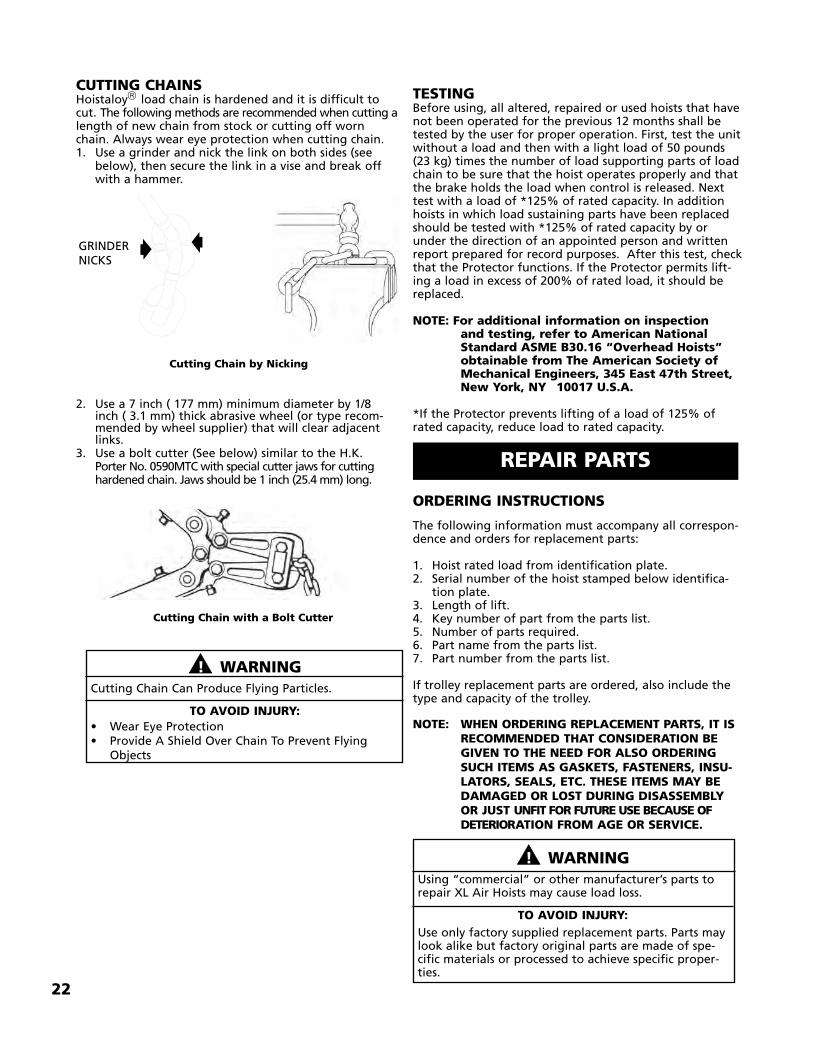
��! WARNINGCutting Chain Can Produce Flying Particles.
TO AVOID INJURY:• Wear Eye Protection• Provide A Shield Over Chain To Prevent Flying
Objects
��! WARNINGUsing “commercial” or other manufacturer’s parts torepair XL Air Hoists may cause load loss.
TO AVOID INJURY:Use only factory supplied replacement parts. Parts maylook alike but factory original parts are made of spe-cific materials or processed to achieve specific proper-ties.
REPAIR PARTS
CUTTING CHAINSHoistaloy load chain is hardened and it is difficult tocut. The following methods are recommended when cutting alength of new chain from stock or cutting off wornchain. Always wear eye protection when cutting chain.1. Use a grinder and nick the link on both sides (see
below), then secure the link in a vise and break off with a hammer.
2. Use a 7 inch ( 177 mm) minimum diameter by 1/8 inch ( 3.1 mm) thick abrasive wheel (or type recom-mended by wheel supplier) that will clear adjacent links.
3. Use a bolt cutter (See below) similar to the H.K. Porter No. 0590MTC with special cutter jaws for cuttinghardened chain. Jaws should be 1 inch (25.4 mm) long.
GRINDERNICKS
Cutting Chain by Nicking
Cutting Chain with a Bolt Cutter
23
Repair Parts
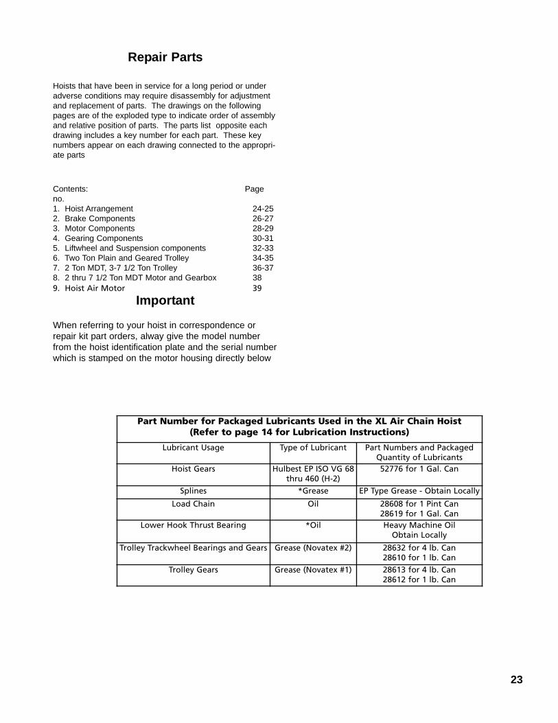
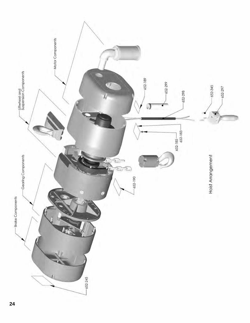
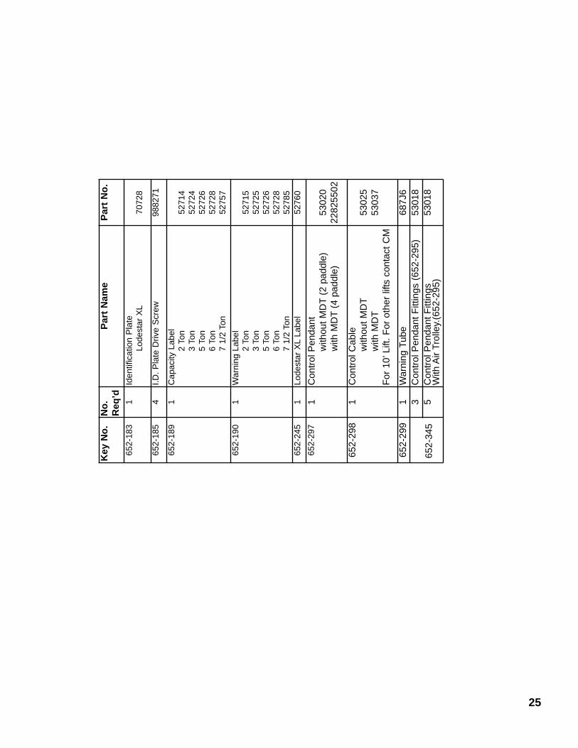
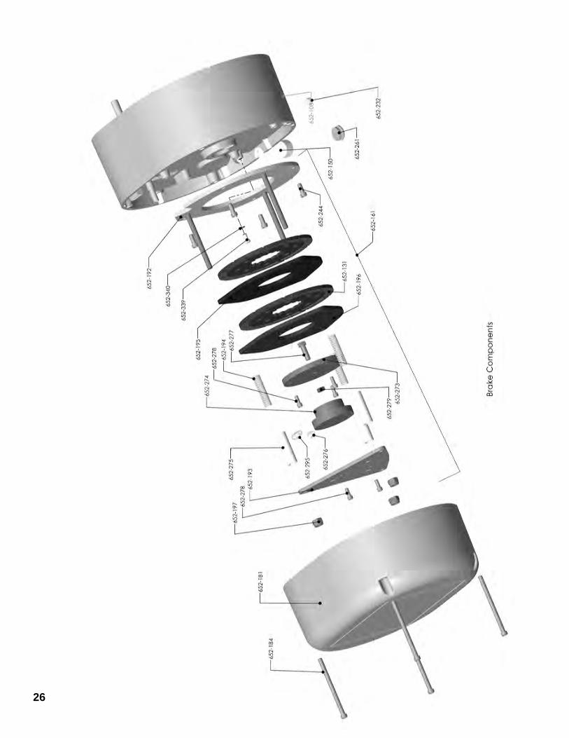
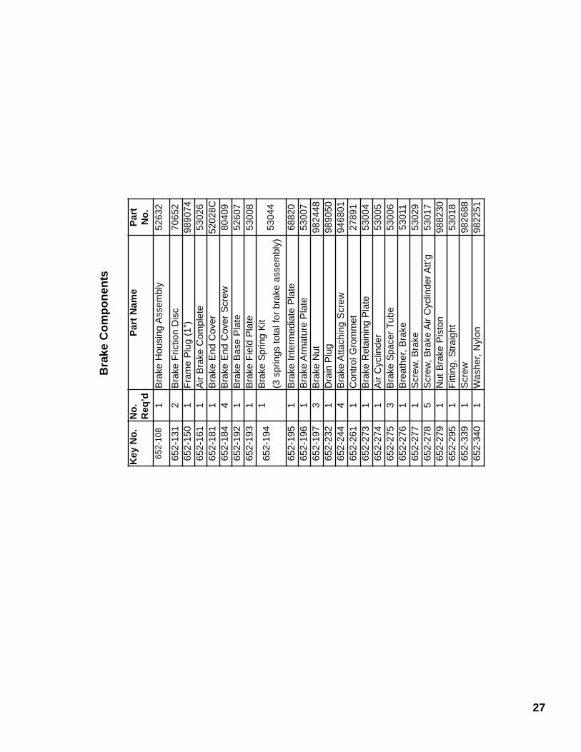
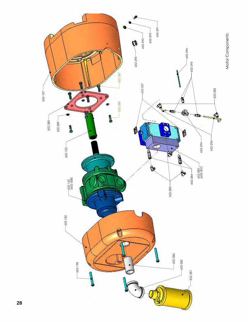
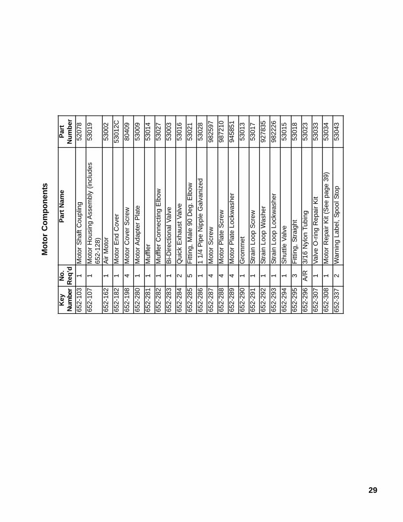
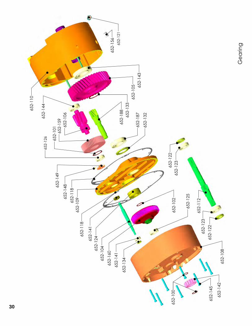
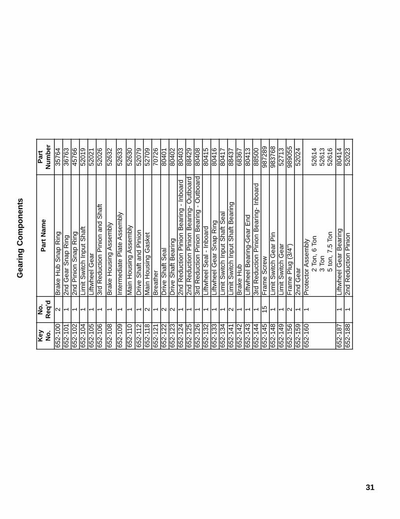
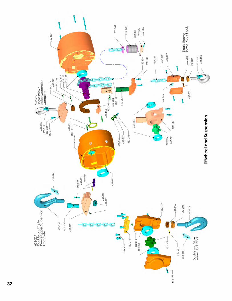
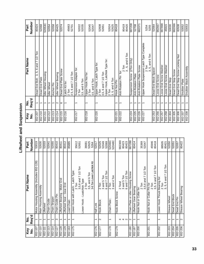
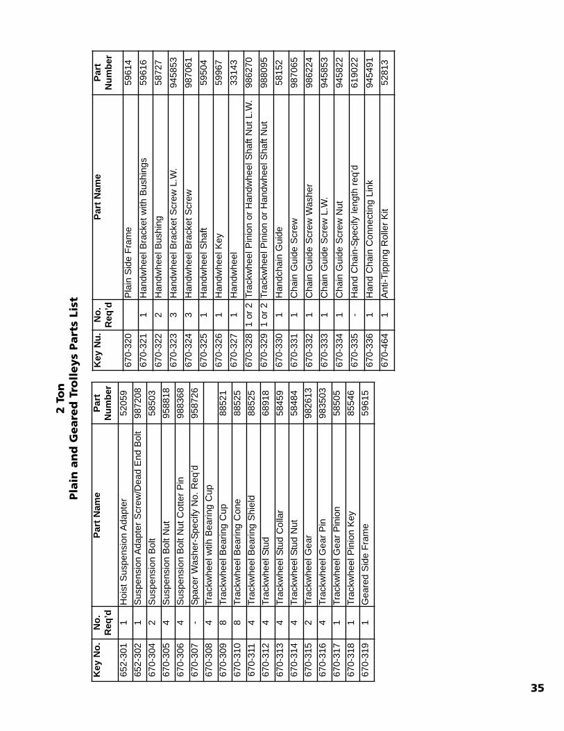
Hoists that have been in service for a long period or underadverse conditions may require disassembly for adjustmentand replacement of parts. The drawings on the followingpages are of the exploded type to indicate order of assemblyand relative position of parts. The parts list opposite eachdrawing includes a key number for each part. These keynumbers appear on each drawing connected to the appropri-ate parts
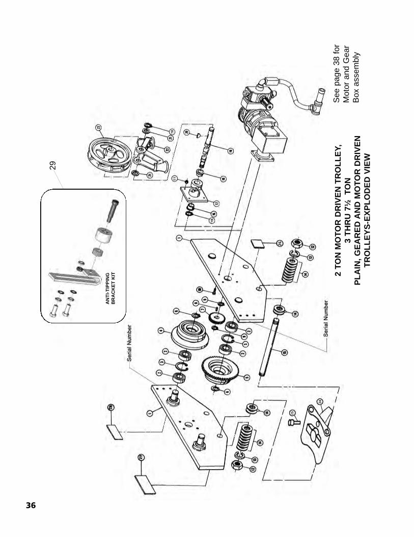
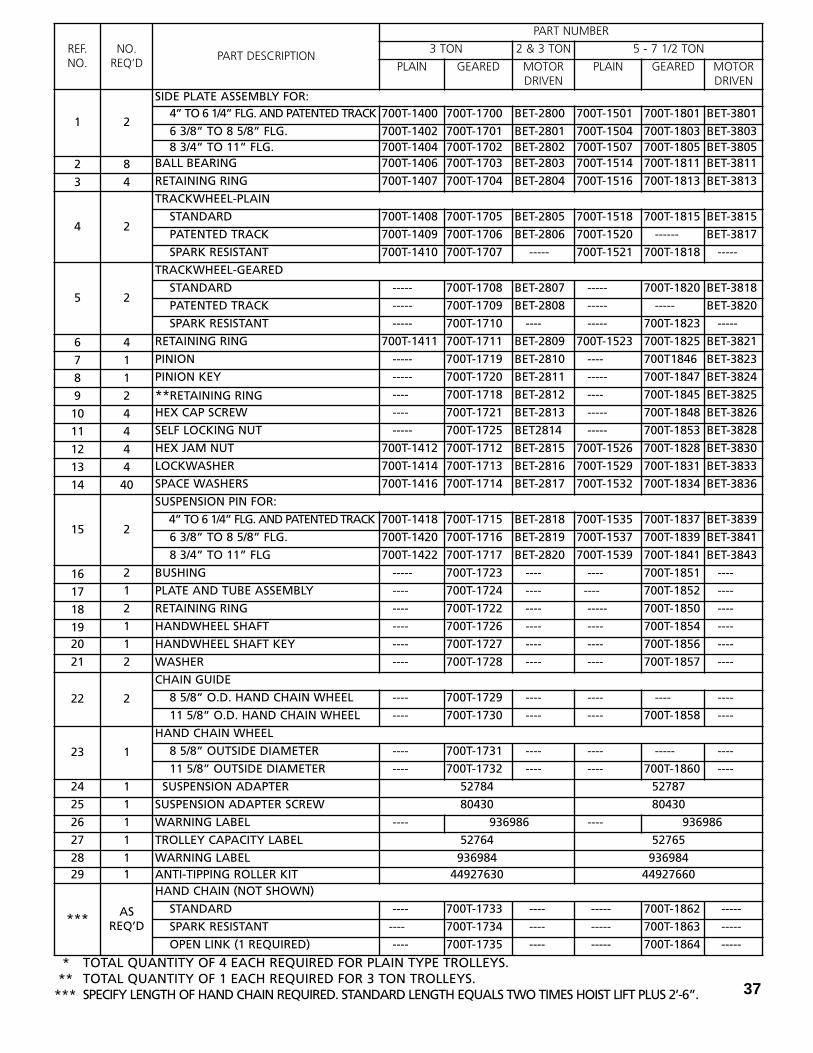
Contents: Pageno.1. Hoist Arrangement 24-252. Brake Components 26-273. Motor Components 28-294. Gearing Components 30-315. Liftwheel and Suspension components 32-336. Two Ton Plain and Geared Trolley 34-357. 2 Ton MDT, 3-7 1/2 Ton Trolley 36-378. 2 thru 7 1/2 Ton MDT Motor and Gearbox 389. Hoist Air Motor 39
Important
When referring to your hoist in correspondence orrepair kit part orders, alway give the model numberfrom the hoist identification plate and the serial numberwhich is stamped on the motor housing directly below
Part Number for Packaged Lubricants Used in the XL Air Chain Hoist(Refer to page 14 for Lubrication Instructions)
Lubricant Usage Type of Lubricant Part Numbers and PackagedQuantity of Lubricants
Hoist Gears Hulbest EP ISO VG 68thru 460 (H-2)
52776 for 1 Gal. Can
Splines *Grease EP Type Grease - Obtain Locally
Load Chain Oil 28608 for 1 Pint Can28619 for 1 Gal. Can
Lower Hook Thrust Bearing *Oil Heavy Machine OilObtain Locally
Trolley Trackwheel Bearings and Gears Grease (Novatex #2) 28632 for 4 lb. Can28610 for 1 lb. Can
Trolley Gears Grease (Novatex #1) 28613 for 4 lb. Can28612 for 1 lb. Can
* TOTAL QUANTITY OF 4 EACH REQUIRED FOR PLAIN TYPE TROLLEYS.** TOTAL QUANTITY OF 1 EACH REQUIRED FOR 3 TON TROLLEYS.*** SPECIFY LENGTH OF HAND CHAIN REQUIRED. STANDARD LENGTH EQUALS TWO TIMES HOIST LIFT PLUS 2’-6”. 37
REF.NO.
NO.REQ’D
PART DESCRIPTION
PART NUMBER
3 TON 2 & 3 TON 5 - 7 1/2 TON
PLAIN GEARED MOTORDRIVEN
PLAIN GEARED MOTORDRIVEN
1 2
SIDE PLATE ASSEMBLY FOR:4” TO 6 1/4” FLG. AND PATENTED TRACK 700T-1400 700T-1700 BET-2800 700T-1501 700T-1801 BET-3801
OPEN LINK (1 REQUIRED) ---- 700T-1735 ---- ----- 700T-1864 -----
�
�
�
��
�
�
�
�
��
3 THRU 7½ TON MOTOR AND GEAR BOX ASSEMBLY
TROLLEY BRAKE(OPTIONAL)
*SEE PAGE 39 FOR TROLLEY BRAKE ASSEMBLY
Ref. No. No. Req’d Part Description Part Number
1 1 Gear Box Assembly BET-3003
2 1 Air Brake Contact Factory
3 1 Air Motor 22721301
4 1 Mounting Plate 22925703
5 1 Sandwich Plate 22925501
6 1 Valve 22746302
7 1 Muffler 227472-1
8 1 Air Hose Assembly 53042
9 1 Hex Bushing 53039
10 1 Reducing Tee 53040
11 1 Pipe Nipple 53041
12 * 1 Gasket 11443301
13 * 1 Gasket 22746801
38
2 THRU 7 1/2 TON MOTOR AND GEAR BOX ASSEMBLY
* Not Shown
Seepage 39
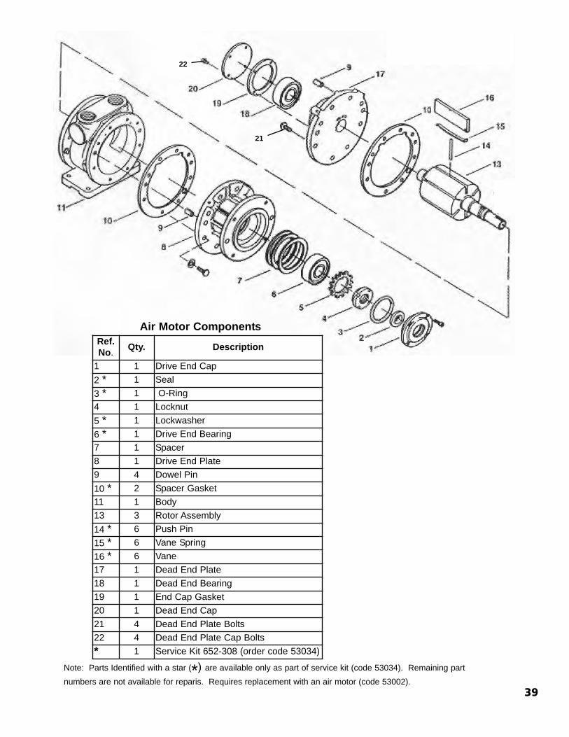
Air Motor ComponentsRef.No. Qty. Description
1 1 Drive End Cap2 * 1 Seal3 * 1 O-Ring4 1 Locknut5 * 1 Lockwasher6 * 1 Drive End Bearing7 1 Spacer8 1 Drive End Plate9 4 Dowel Pin10 * 2 Spacer Gasket11 1 Body13 3 Rotor Assembly14 * 6 Push Pin15 * 6 Vane Spring16 * 6 Vane17 1 Dead End Plate18 1 Dead End Bearing19 1 End Cap Gasket20 1 Dead End Cap21 4 Dead End Plate Bolts22 4 Dead End Plate Cap Bolts* 1 Service Kit 652-308 (order code 53034)
39
Note: Parts Identified with a star (*) are available only as part of service kit (code 53034). Remaining partnumbers are not available for reparis. Requires replacement with an air motor (code 53002).
Note: When ordering parts, always furnish Hoist Model and Serial Number,Motor Horsepower, Voltage, Phase, Frequency and Rated Capacity of hoist onwhich the parts are to be used.For the location of the nearest Master Parts Depot, see the list located on theinside front cover.
Columbus McKinnon Corporation140 John James Audubon ParkwayAmherst, New York 14228-1197 Phone: (800) 888-0985 Fax: (716) 689-5644
LIMITATION OF WARRANTIES, REMEDIES AND DAMAGES
THE WARRANTY STATED BELOW IS GIVEN IN PLACE OF ALL
OTHER WARRANTIES, EXPRESS OR IMPLIED, OF MER-
CHANTABILITY, FITNESS FOR A PARTICULAR PURPOSE, OR
OTHERWISE, NO PROMISE OR AFFIRMATION OF FACT MADE
BY ANY AGENT OR REPRESENTATIVE OF SELLER SHALL CON-
STITUTE A WARRANTY BY SELLER OR GIVE RISE TO ANY LIA-
BILITY OR OBLIGATION.
Seller warrants that on the date of delivery to carrier the
goods are free from defects in workmanship and materials.
SELLER’S SOLE OBLIGATION IN THE EVENT OF BREACH OF
WARRANTY OR CONTRACT OR FOR NEGLIGENCE OR OTHER-
WISE WITH RESPECT TO GOODS SOLD SHALL BE EXCLUSIVELY
LIMITED TO REPAIR OR REPLACEMENT, F.O.B. SELLER’S POINT
OF SHIPMENT, OF ANY PARTS WHICH SELLER DETERMINES TO
HAVE BEEN DEFECTIVE or if Seller determines that such repair
or replacement is not feasible, to a refund of the purchase
price upon return of the goods to Seller.
Any action against Seller for breach of warranty, negligence
or otherwise, must be commenced within one year after such
cause of action accrues.
NO CLAIM AGAINST SELLER FOR ANY DEFECT IN THE GOODS
SHALL BE VALID OR ENFORCEABLE UNLESS BUYER’S WRITTEN
NOTICE THEREOF IS RECEIVED BY SELLER WITHIN ONE YEAR
FROM THE DATE OF SHIPMENT.
Seller shall not be liable for any damage, injury or loss arising
out of the use of the goods if, prior to such damage, injury or
loss, such goods are (1) damaged or misused following Seller’s
delivery to carrier; (2) not maintained, inspected, or used in
compliance with applicable law and Seller’s written instruc-
tions and recommendations; or (3) installed, repaired, altered
or modified without compliance with such law, instructions or
recommendations.
UNDER NO CIRCUMSTANCES SHALL SELLER BE LIABLE FOR
INCIDENTAL OR CONSEQUENTIAL DAMAGES AS THOSE
TERMS ARE DEFINED IN SECTION 2-715 OF THE UNIFORM
COMMERCIAL CODE.
INDEMNIFICATION AND SAFE OPERATION
Buyer shall comply with and require its employees to comply
with directions set forth in instructions and manuals fur-
nished by Seller and shall use and require its employees to
follow such instructions and manuals and to use reasonable
care in the use and maintenance of the goods. Buyer shall
not remove or permit anyone to remove any warning or
instruction signs on the goods. In the event of personal injury
or damage to property or business arising from the use of the
goods, Buyer shall within 48 hours thereafter give Seller writ-
ten notice of such injury or damage. Buyer shall cooperate
with Seller in investigating any such injury or damage and in
the defense of any claims arising therefrom.
If Buyer fails to comply with this section or if any injury or
damage is caused, in whole or in part, by Buyer’s failure to
comply with applicable federal or state safety requirements,
Buyer shall indemnify and hold Seller harmless against any
claims, loss or expense for injury or damage arising from the
use of the goods.
®
�� ! WARNINGAlterations or modifications of equipment and use ofnon-factory repair parts can lead to dangerous opera-tion and injury.
TO AVOID INJURY:• Do not alter or modify equipment• Do use only factory provided replacement parts.