52B14SE6X927 6 3.2843 HUTCHINSON 010 AIRBORNE GEOPHYSICAL SURVEY ATIKOKAN PROJECT SABAWI LAKE AREA FOR KEMINS EXPLORATIONS LIMITED BY CANADIAN AERO MINERAL SURVEYS LIMITED PROJECT 092 OTTAWA, ONTARIO, January 21, 1970. J.E. Mekarski, B.Se., Geophysicist. CANADIAN AERO ghtMwyti M
Transcript
52B14SE6X927 63.2843 HUTCHINSON 010
AIRBORNE GEOPHYSICAL SURVEY
ATIKOKAN PROJECT
SABAWI LAKE AREA
FOR
KEMINS EXPLORATIONS LIMITED
BY
CANADIAN AERO MINERAL SURVEYS LIMITED
PROJECT 092
OTTAWA, ONTARIO, January 21, 1970.
J.E. Mekarski, B.Se., Geophysicist.
CANADIAN AERO ghtMwyti M
I. INTRODUCTION
This report pertains to the combined airborne
electromagnetic and magnetic survey flown on behalf of Kemins
Explorations Limited over a group of claims in Schwenger, McCaul,
Hutchinson and Trottier Twonships, herein called the Sabawi Lake
area , Rainy River District, Ontario. The survey was conducted
on December 15 and 16, 1969 by Canadian Aero Mineral Surveys
Limited, using a geophysically equipped Otter aircraft CF-IGM
based at Port Arthur. About 208 miles of geophysical data were
obtained.
The following Canadian Aero Mineral Surveys Limited
personnel were associated with this project:
B. Duperron Pilot
R. Bolivar Navigator
L. May Aircraft Mechanic
P. Rautenberg Geophysical Operator
D. Fitzsimmons Chief Draftsman
E. Rockel
D. Vohra
J. Mekarski
Geophysicist
Geophysicist
Geophysicist,
Note: The second half of the survey "Chief Peter Lake Area" is described in a separate report.
CANADIAN AERO
- 2 -
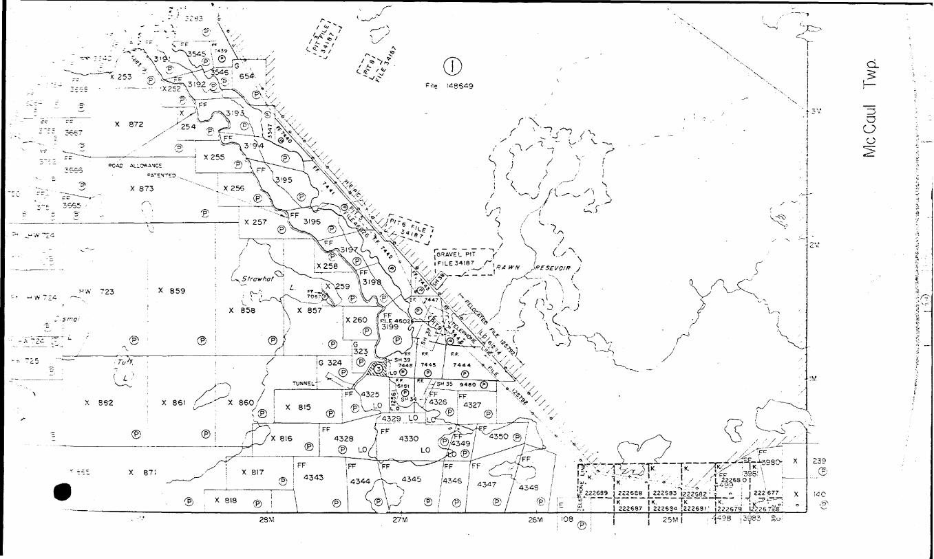
An airphoto laydown provided a base for the maps
presented. Flight lines were spaced about 1000 feet apart.
E.M. conductors and coincident magnetic anomalies were plotted
on a plan map at a scale of l inch ^ \ mile.
II. GEOLOGY
Geology used in this report was obtained from:
1) Ontario Department of Mines - Map 2065,
Atikokan - Lakehead Sheet, 1964.
2) Sketch map and general description provided
by Kemins Explorations Limited.
The survey area straddles the Atikokan River.
It lies along the contact of undifferentiated metavolcanic rocks
(formerly classified as Keewatin) to the north, and metasediments
(arkose, graywacke, slate, mica schist, and gneiss, formerly
classified as Couchiching or Keewatin) to the south.
An east-west trending fault extends along the
contact between metavolcanics and metasediments. Lying along
this contact are several iron formations, a zone of gabbro -norite,
and interbedded overlapping bodies of sulphides such as pyrite
and pyrrhotite, and magnetite. A bulk sample from the zone
assyed Q.78% Cu, 0.1270 Ni, and 0.0870 Co.
CANADIAN AERO iMmekal
- 3 -
Archean granite and related rocks lie to the north
and south of the metavolcanic - metasedimentary belt, and to the
southeast of Sabawi Lake.
III. DISCUSSION OF RESULTS
Fourteen E.M. conductors were outlined by the
airborne survey of the Sabawi Lake area. They are labelled
sequentially from west to east by encircled numbers.
Conductor l is underlain by metavolcanics. It is
characterized by low amplitude of E.M. response, poor in-phase
to quadrature ratio, and no associated magnetic anomaly. The
conductor has been graded as doubtful because of the above
characteristics, and because its location coincides with a power
line, and may be wholly or in part caused by it.
Conductors 2, 3, 5, 6, 7, 10, 12, 13 and 14, lie
along the contact of metavolcanics to the north and metasediments
to the south. They coincide with the axis of a fault, several
iron formations, and occurrences of sulphides containing copper,
nickel, and cobalt.
Geophysically, this group of conductors lies along
a east-northeast trending magnetic ridge. Cursory comparison of
several magnetic profiles in the western portion of the area with
mathematically generated curves of sheet models, suggests that this
CANADIAN AERO j&U/MWUA
- 4 -
4magnetic feature dips to the north. In general amplitude of E.M.
response is fairly high, in-phase to quadrature ratio of these
anomalies is much greater than one (good conductivity), and
amplitudes of coincident magnetic peaks very high (as expected
of iron formation).
Although most of the E.M. profiles have a single
peak, portions of conductors 2 and 3 have double peaks, and the
east end of conductor 7 multiple peaks, implying several conduc
tive bodies in these areas.
The grouping of conductors 8, 9, 10, 11 and the
east end of 7 may be significant, in that such a configuration
might be obtained at a fault intersection.
Conductor 4 is underlain by metavolcanic rocks.
It is characterized by low E.M. amplitude, in-phase to quadrature
ratio less than one (poor conductivity) and no associated magnetic
anomaly, hence it is a follow-up target of very low priority.
Conductors 8 and 9 are also underlain by metavol-
canics, and are characterized by low E.M. amplitude. Their
in-phase to quadrature ratios indicate a better conductivity than
that of conductor 4. A small magnetic peak coincides with
conductor 9. These conductors may be related, and are low priority
follow-up targets.
CANADIAN AERO
- 5 -
Conductor 11, underlain by metasediments, is
located northwest of, and adjacent to an area of granite. This
conductor has both high (T-46A) and low (T-46B) E.M. amplitude
accompanied by in-phase to quadrature ratio greater than three
(characteristic of a good conductor) and less than one (poor
conductor) respectively. Portions of this conductor coincide
with a magnetic anomaly of low amplitude. Although this
conductor may be "genuine" (caused by sulfides), numerous
cultural features such as buildings, railway tracks and power
lines may have wholly or in part produced this anomaly. The
conductor is therefore a low priority follow-up target.
IV. CONCLUSIONS AND RECOMMENDATIONS
Because of sulphides encountered in this area, and
presence of associated copper, nickel, and cobalt, a thorough
exploration and drilling program should be carried out, during
which the conductors may be examined in the following sequence:
2, 3, 13, 6, 5, 7, 14, 10, 9, 12, 8, 4, and 11. Conductors 2 and
3 are easily accessible, have short strike length, are near water,
and should be drilled first. Results of this relatively inexpen
sive drilling should be used as a guide in further exploration.
Respectively submitted,
OTTAWA, ONTARIO, J.E. Mekarski, B.Se., January 21, 1970. Geophysicist.
CANADIAN AERO jHmebdl 0
PROJECT NO. 092
t
^
1Anomaly
2A
3A
11A
B
12A
13A
14A
19A
20A
21A
B
24A
25A
27A
28A
29A
32A
33A
34A
35A
36A
Fiducials
7588/91
7507 /8
6836/7
6838/9
6766/70
6678/82
6599/601
6169/71
6084/88
5992/94
5997/99
5746/48
5674/78
5502/04
5411/14
5342/44
5075/78
4999/5001
4899/901
4845 /7
4743/45
In- Phase Quad
30/30
30/20
30/10
20/20
440/-
330/40
90/70
230/80
420/170
280/0
30/50
130/80
60/30
120/160
270/130
120/30
30/30
100/0
80/0
40/0
70/0
- SABAWI LAKE AREA
Altitude
190
160
170
110
120
160
125
110
120
155
165
130
130
120
120
130
145
145
100
140
140
Magnetics Rate Comments
NIL
NIL
S. Edge 850
N. Edge 850g
Assoc. 4200g
Direct 4500g
Direct 400g
Direct 1200g
Assoc. 4500g
Direct 1700g
NIL
Direct 2200g
Direct 4500g
Direct 7500g
Direct 7000g
Direct 1600g
Direct lOOOg
Direct 2200g
Direct 2000g
Direct lOOOg
Direct HOOg
X Power line?
X Power line?
3
3
2B Double, - Out- of - Phase neg.
2A Out- of - phase - Suppressed
3
3
2B Double
2A
3
3
3
3
2A
3
3
3
3
3
3
CANADIAN AERO v4un0Mll •^ ^^L,m
. j
0
*
tAnomaly
37A
38A
39A
40A
41A
42A
B
43A
44A
45A
46A
B
C
47A
B
48A
53A
55A
56A
PROJECT NO. 092
Fiducials
4693/96
4584/86
4538/40
4411/14
4381/83
4251/59
4237/38
4135 /40
4048/50
3967/70
3911/14
3208/910
3889/891
3768/770
3784/87
3738/40
3284/86
3124/26
3028/31
In-Phase Quad
70/0
50/20
90/0
70/-
50/0
60/50
30/20
40/30
20/30
20/20
720/210
60/120
60/50
40/30
40/20
40/40
90/0
30/30
30/50
- SABAWI LAKE AREA
Altitude
155
140
150
145
175
155
100
160
85
155
50
60
110
80
120
80
165
180
135
Magnetics Rate
Direct 900g 3
Direct 850g 3
Direct 1900g 3
Direct 2200g 3
Direct 1700g 3
Assoc. (direct)3 1600g
NIL 3
N. Side HOOg 3
Direct 40g 3
S. Flank 20g 3
Assoc. 620g 2B
NIL 3
N. Edge lOOOg 3
Direct 30g 3
Assoc. 1400g 3
N. Flank 40g 3
Direct 450g 3
Direct 500g 3
Direct 1900g 3
Comments
Quadrature-- Broad
Weak
Weak - Multiple
Weak
Weak
Cultural feature
Cultural feature
Cultural feature
Double - Weak
Cultural feature
Multiple?
CANADIAN AERO tMwiehat f&U/MmiA^^
1 PROJECT NO. 092
ft
ft
ft
1Anomaly
57A
58A
59A
60A
61A
62A
63A
64A
65A
66A
67A
68A
69A
71A
72A
Fiducials
2943/45
2847/49
2783/85
2686/90
2615/17
2511/14
2447/49
2339/41
2266/68
2159/62
2101/03
1988/90
1932/4
1757/58
1634/6
In- Phase Quad
100/0
210/30
160/40
400/240
530/100
510/50
110/40
220/120
160/20
450/0
230/0
40/0
140/40
20/0
120/90
- SABAWI LAKE AREA
Altitude
145
125
125
135
90
115
145
110
165
125
150
130
150
145
110
Magnetics Rate Comments
Direct 2700g 3
Direct 3700g 3
Direct 7000g 3
Direct 9000g 2A
S. Edge 6000g 2B
Direct 4600g 2A
Direct 2500g 3
Direct 2700g 3
Direct 1600g 2A
Direct 2400g 2A
Direct 3200g 2A
Direct 1800g 3
Direct 1500g 3
S. Side 230g 3
Direct 1400g 3
CANADIAN AERO tMwWMli j&U/MmiA^^
APPENDIX II
A. EQUIPMENT
The electromagnetic unit and the magnetometer are the key instruments in the Canadian Aero Mineral Surveys Limited Otter survey system. The remainder of the equipment consist of a radar altimeter, a spectrometer, an accelerometer, a continuous - strip camera, three recorders and a fiducial numbering system.
The EM unit is the Canadian Aero Service Limited MARK IV low frequency (320 c.p.s.) in-phase/out-of-phase system. The transmitting and receiving coils are mounted on the wingtips of the Otter, with a vertical coplanar orientation and a separation of 61 feet. An electronic null device is adjusted so that in the absence of a conductor within the range of the system no signal is recorded. The anomalous signal is divided into two components, the "in-phase" component having the same phase as the tranmitted field and the "quadrature" or "out-of-phase" component being at right angles to it. These two measurements are recorded on two channels of the six-channel rectilinear recorder.
Variations in the total magnetic field of the earth are measured by a Gulf Fluxgate magnetometer mounted in the aircraft. Anomalies as small as 10 gammas can normally be distinguished. The output of the magnetometer is presented as one channel on the six-channel recorder to facilitate correlation with the EM traces. It is also presented at a larger scale and in rectilinear form on a separate recorder, these recording being used in the preparation of isomagnetic contour maps whenever they are required.
A Bonzer radar altimeter provides a terrain clearance profile on one channel of the six-channel recorder. Because EM response decays rapidly with increasing altitude this altitude information is important in the analysis of the EM data.
A vertical accelerometer mounted in the aircraftprovides a record of the air turbulence and of any drastic manoeuvres of the aircraft. The accelerometer trace on the six-channel recorder is often helpful in recognizing spurious blips on the EM traces caused by air turbulence or drastic manoeuvres.
APPENDIX II - cont'd. lage 2
The gamma ray spectrometer is manufactured byHanmer Electronic Products, a division of Harshaw Chemical Company, to Aero Service specifications. Three 6-inch diameter by 4-inch thickness thallium activated sodium iodide crystals are utilized. Ratemeter ranges cover count rates from 100 c.p.s. to 100,000 c.p.s. with a choice of time constants from 0.25 to 10 seconds. Upper and lower threshold settings are continuously adjustable allowing for the discrimination of potassium, uranium and thorium. Results are presented on a rectilinear recorder together with altimeter data.
The entire flight path is photographed by a vertically - mounted Aeropath 35 mm. continuous-strip camera.
Synchronization of the film strip with the three recorders is accomplished by means of an automatic fiducial numbering system which prints simultaneous time markers on all records at regular time intervals, normally every ten seconds.
Due to the time constant used in the electromagnetic unit, both the EM in-phase and quadrature recordings are delayed by approximately l second. This is taken into account when plotting the position of each anomaly.
B. DESCRIPTION OF RECORDS
Rectilinear Magnetic Record
With the chart oriented so that fiducial numbers increase from right to left, upward deflections on the chart indicate increases in the total magnetic field of the earth. On the 1200 scale the smallest division on the chart is approximately equivalent to 10 gammas. When the record "steps" a change of approximately 1000 gammas is indicated.
The fiducial marks are normally spaced at 10-second intervals, a spacing which is equivalent to approximately 1500 feet on the ground. The exact horizontal scale of the tape can be established by measuring the fiducial spacing on the map.
APPENDIX II - cont'd. (age 3
Brush Six-Channel Record
With the chart oriented so that fiducial numbers increase from right to left the tracings from the bottom to the top of the chart are as follows:
Fiducial markers - same comments as above.
Channel 1) Magnetometer - positive upward. On the 1200 scale l minor division is approximately equivalent to 25 gammas and a step is approximately 1000 gammas.
Channel 2) EM In-Phase - positive upward. l minor division represents approximately 20 parts per million, referred to the primary field at the receiving coil.
Channel 3) EM Quadrature - positive upward. Same scale as In-Phase.
Channel 4) Radar Altimeter, Altitude increases upwards. 150' centre line and 300' top line of channel.
Channel 5) Accelerometer - an acceleration of \ "G" is equivalentto a 5 minor divisions deflection from the central point.
Channel 6) Spectrometer total count.
Fiducial markers - same comments as above.
When a spectrometer survey is included, the information is recorded on a Clevite 6" Rectilinear light sensitive recorder. Window settings and counts used are specified in the accompanying report.
C. SURVEY AND MAP COMPILATION PROCEDURES
Uncontrolled airphoto mosaics usually serve as base maps for flying the survey and for compilation of the geophysical data. The most common scale is 1/4 mile per inch.
The flight lines are oriented perpendicular to theassumed longest dimension of massive sulphide occurrences anticipated in the survey area. Occasionally two or more line directions have to be used to accommodate changes of geological strike within the area. Line spacings normally range between 1/8 mile and 1/4 mile.
PPENDIX II - cont'd. age 4
The navigator is provided with "flight strips" of the area to be surveyed. These flight strips are a copy of the airphoto mosaic, with the intended flight lines inked and numbered. Navigation along the parallel flight lines is accomplished by visual means based on the physical detail observed on the photos. The aircraft is flown at a terrain clearance of 150 feet or, inrough terrain, at the lowest safe altitude.
\
Flight path is recovered in the field by comparison of the 35 mm. strip film with the airphoto mosaics. Identifiable points are marked on the mosaics and designated by numbers determined from the fiducial numbering system on the film. These recovered flight lines provide the positional basis for plotting the geophysical data. The EM anomalies are listed and graded in the field and are often plotted on the field mosaics to permit immediate acquisition of ground.
In our Ottawa office screened positives of the mosaics are prepared, upon which are drafted the recovered fiducial points, the interpolated flight lines positions and the significant geophysical data. The geophysical data are subjected to a careful analysis by a geophysicist who prepares an interpretation report including recommendations for further work.
D. DATA PRESENTATION
The data presentation procedure which we employ for the Otter geophysical system is a combination of an anomaly listing and a plan map plot of graded EM anomalies. The anomaly listing provides the significant details concerning each anomaly and the map gives a "bird's eye view" of the conductors detected.
For purposes of listing and to facilitate reference in the report each EM anomaly'is assigned a "name", which is made up of the number of the line upon which the anomaly occurs plus a letter. For example, on line 257 anomalies would be named 257A, 257B, 257C, etc., from south to north or from west to east. The letter which appears beside each EM anomaly on the map is therefore part of its name. These names also appear on the Brush records and in the anomaly list.
APPENDIX II - cont'd. jage 5
The anomaly list contains the fiducial numbers at the edges of the EM anomaly, the in-phase and quadrature amplitudes in p.p.m., the altitude at which the anomaly was detected, the positional relationship of the EM anomaly to magnetic anomalies (if any), a rating, and comments concerning any other pertinent characteristics of the anomaly.
The nomenclature used in the "magnetics" column of the anomaly list requires some explanation. The main terms used are side, flank, edge and direct. These refer to the position of the EM peak relative to the axis of the magnetic feature. "Direct" depicts coincident peaks and similar widths; "edge" is slightly offset; "flank" is somewhere along the flank of the magnetic anomaly; "side" is down near the base. "N. Flank 800g" means that the EM anomaly occurs along the northern flank of a magnetic feature of 800 gammas total amplitude. When one peak of a multiple EM anomaly coincides with a magnetic high the specific peak may be designated. For example, if the southern peak of a double EM anomaly coincided with a 250 gamma magnetic anomaly the nomenclature would be "Dir. S. 250g".
The rating assigned to each EM anomaly in the listing determines the symbol which represents the anomaly on the map. Six categories of anomalies are defined: 1A, IB, 2A, 2B, 3, and X. The numbers "l", "2" and "3" are primarily a measure of in-phase amplitude corrected for altitude variation: "l" is for very large anomalies, "2" for intermediate, and "3" for relatively weak response. This rating is sometimes affected by the shape, by the in-phase to quadrature ratio, or by the location of the anomaly. The letters "A" and "B" merely refer to the magnetics: "A" indicates a directly coincident magnetic anomaly, and "B" indicates the lack thereof. The "X" rating is reserved for questionable anomalies. The legend on the map shows the symbol used for each of these ratings. In general, the more the rectangle is filled in, the stronger the anomaly.
In the case of directly coincident magnetic anomalies, the amplitude of the magnetic feature is shown on the EM map. It is stencilled beneath the symbol which portrays the EM anomaly.
During the final interpretation stage, EM anomalies are correlated from line to line wherever possible and the conductive zones are outlined. All definite conductors are numbered on the map and discussed in the report.
Ill U
llll
llll
llll
.l.,
...
,---
- 52
BHSE
8a27
63.
2843
HUT
CHIN
SON
90
0
x"'"
TI '
-o
. 0 (''l - i
". * •t c CO
'
7)
m
;.x-y •; O
)'•'•
Q i ..i*,- .
*-7-' rn •' ;
^:
'"S-
VI j f'1'1
-" I..
"c ^
: --..'--2y* • • j ^S l 22Z687 222684 J22268ae M j *:^tisf 1^ z.^ l *Tr^ ' t-^T—-^4-^-1
•rt l l ' * ^ 1-^S^S^^-n l it otcon
li l l l j !il Z2Z67S , 22267^1 22Z675 | 2Z267I 122Z670J jj__4gOj 222473 l Z2Z4ZQ t 2ZZ42T j