309
Overview of the Aircraft Design Process Prof. Bento Silva de Mattos V60a - May 2011
| Date post: | 01-Dec-2014 |
| Category: |
Documents |
| Upload: | brian-xistos |
| View: | 293 times |
| Download: | 25 times |

Overview of the Aircraft Design Process Prof. Bento Silva de Mattos
V60a - May 2011

Objective
2
This lecture is intended to provide an
overview of the aircraft design process

Content • Introduction
• The Product Development Process
• The Conceptual Design Phase
• The Preliminary Design Phase
• The Detailed Design Phase
• Entry Into Service

4
Introduction

5
Recommended Further Reading
• D. Howe - Aircraft Conceptual Design Synthesis
• Loftin- Subsonic Aircraft: The Evolution and the Matching of Size to Performance. NASA Referendum Publication 1060.
• D. Raymer - Aircraft Design, A Conceptual Approach.
• E. Torenbeek - Synthesis of Airplane Design.
• J. Roskam - Airplane Design Vol. (1-8).
• Askin Isikveren - Quasi-Analytical Modeling and Optimization Techniques For Transport Aircraft Design, PhD. Thesis, 2002.
Introduction

6
• L.Jenkinson, P.Simpkin & D.Rhodes – Civil Jet Aircraft Design
• D.Stinton – The Design of the Aeroplane
• S.Brandt, J.Stiles & R.Whitford – Introduction to Aeronautics – A Design Perspective
• M. Abzug & E. Larrabee – Airplane Stability and Control, Cambridge Press
Recommended Further Reading
Introduction
Specific Industry journals AEROSPACE DAILY
AVIATION WEEK & SPACE TECHNOLOGY
BUSINESS & COMMERCIAL AVIATION
THE WEEKLY OF BUSINESS AVIATION
AEROSPACE DAILY & DEFENSE REPORT
AIRCRAFT ENGINEERING AND AEROSPACE TECHNOLOGY
AEROSPACE AMERICA
AVIATION DAILY
ENGINEERING FAILURE ANALYSIS
ADVANCED ENGINEERING MATERIALS
AVIATION SPACE AND ENVIRONMENTAL MEDICINE
IEEE AEROSPACE AND ELECTRONIC SYSTEMS MAGAZINE
JOURNAL OF AIRCRAFT
PROFESSIONAL ENGINEERING …
Introduction

Designing Aircraft
8
Introduction
Design:
• Not a clear-cut/scientific or completely rational process
– Despite efforts to formalize
– Neat flow charts of steps aren’t real life, still needed as goals
– But! Some systematic procedures available
• Creativity/imagination, but not pure inspiration
• Broad understanding of physical world
• Beware of cookbook approach:
- understand your concept
• Never stop asking questions!

Good Designs
9
Introduction
Source: Prof. Mason, Virginia Tech

The Process
10
Introduction
Source: Prof. Mason, Virginia Tech
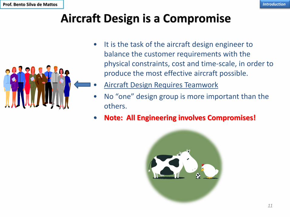
Aircraft Design is a Compromise
11
Introduction
• It is the task of the aircraft design engineer to balance the customer requirements with the physical constraints, cost and time-scale, in order to produce the most effective aircraft possible.
• Aircraft Design Requires Teamwork
• No “one” design group is more important than the others.
• Note: All Engineering involves Compromises!
Prof. Bento Silva de Mattos

Aircraft
• Aeronaves são sistemas multidisciplinares complexos
– Requerem tempo considerável para projetar e construir (vários anos).
– Investimento considerável (custo unitário também elevado).
– Mercado extremamente competitivo.
– Requisitos extremamente exigentes de certificação do produto.
• Incerteza no projeto e desenvolvimento conduz a:
- aeronaves que são entregues fora do prazo e do orçamento.
- aeronaves inadequadas e não-competitivas.
12
Introduction
Prof. Bento Silva de Mattos

Aeronaves São Sistemas Multidisciplinares Complexos
• Sistemas multidisciplinares são intrisincamente difíceis de modelar e entender devido a uma única pessoa não ser capaz de possuir conhecimento detalhado nas áreas requeridas.
• Sistemas frequentemente tornam-se muitos complexos para que se possa reduzir a incerteza e permitir uma previsibilidade razoável. – Requisitos de certificação cada vez mais exigentes.
– Requisitos de desempenho e operação mais exigentes e complexos (ex. aeronaves silenciosas e não-poluentes)
13
Introduction
Prof. Bento Silva de Mattos

14
Think Light, Think Simple, Think Accessibility, Think Maintainability,
and Think after all Cost
Introduction
Prof. Bento Silva de Mattos

15
Kelly Johnson’s Rules for
Project Management
Kelly Johnson established fourteen basic
operating rules to govern his projects.
Within the Skunk Works staff, these
rules were as sacred as the
Ten Commandments.
Many sites across the internet include
these rules. The rules differ slightly from
site to site. The following compilation is
from the stuff obtained them from these
various sites and selected from the
wordings. (For example, later wordings
seem to substitute "customer" for the
military and "vendor" for contractor.).
Introduction
Prof. Bento Silva de Mattos

16
Rule Number 1
The Skunk Works' program manager must be delegated practically complete control of his
program in all aspects. He should report to a division president or higher.
Rule Number 2
Strong but small project offices must be provided both by the military and industry.
Rule No. 3
The number of people having any connection with the project must be restricted in an almost
vicious manner. Use a small number of good people (10 percent to 25 percent compared to
the so-called normal systems).
Rule No. 4
A very simple drawing and drawing release system with great flexibility for making changes
must be provided.
Rule No. 5
There must be a minimum number of reports required, but important work must be recorded
thoroughly.
Kelly Johnson’s Rules
Introduction
Prof. Bento Silva de Mattos

17
Rule No. 6
There must be a monthly cost review covering not only what has been spent and committed
but also projected costs to the conclusion of the program. Don't have the books ninety days
late and don't surprise the customer with sudden overruns.
Rule No. 7
The contractor must be delegated and must assume more than normal responsibility to get
good vendor bids for subcontract on the project. Commercial bid procedures are very often
better than military ones.
Rule No. 8
The inspection system as currently used by the Skunk Works, which has been approved by
both the Air Force and the Navy, meets the intent of existing military requirements and
should be used on new projects. Push more basic inspection responsibility back to the
subcontractors and vendors. Don't duplicate so much inspection.
Rule No. 9
The contractor must be delegated the authority to test his final product in flight. He can and
must test it in the initial stages. If he doesn't, he rapidly loses his competency to design other
vehicles.
Kelly Johnson’s Rules
Introduction
Prof. Bento Silva de Mattos

18
Rule No. 11
Funding a program must be timely so that the contractor doesn't have to keep running to the
bank to support government projects.
Rule No. 12
There must be absolute mutual trust between the military organization and the contractor
with very close liaison on a day-to-day basis. This cuts down misunderstanding and
correspondence to an absolute minimum.
Rule No. 13
Access by outsiders to the project and its personnel must be strictly controlled by
appropriate security measures.
Rule No. 14
Because only a few people will be used in engineering and most other areas, ways must be
provided to reward good performance by pay, not simply related to the number of personnel
supervised.
Kelly Johnson’s Rules
Introduction
Prof. Bento Silva de Mattos

19
Rule 15
Several sites suggest that there was an additional "unwritten rule" . . .
Rule No. 15
Never deal with the Navy.
Kelly Johnson’s Rules
Introduction
Prof. Bento Silva de Mattos

20
"Be Quick, Be Quiet, And Be on Time"
Kelly Johnson’s Most
Important Rule
Introduction
Prof. Bento Silva de Mattos

Weight Definitions • disposable load = payload + useable fuel (+any necessary ballast)
Where
Payload = the revenue earning load
Maximum ramp weight is that approved for ground maneuver
Maximum ramp weight = maximum take-off weight + start, taxi, and run-up fuel
Maximum landing weight = maximum weight approved for touchdown
Maximum zero fuel weight = the maximum weight approved – usable fuel
Prof. Bento Silva de Mattos

• APS weight (aircraft prepared for service), which is the same as the basic
empty weight, i.e. fully equipped operational, without crew, usable fuel or
payload (the load that generates revenue, income).
• AUW, Wo The all-up (gross) weight is the maximum weight at which flight
requirements must be met.
Maximum to take-off weight = gross (all-up) weight = MTOW
= operating empty weight + disposable load
in which operating empty weight and disposable load are built up as
follow
Operating empty weight = basic empty weight + crew
Basic empty weight = standard empty weight + optional equipment
Standard empty weight = weight of the standard aircraft (as
manufactured + unusable fuel + full operating fluids + full engine oil

Taper ratio is the term given to the ratio
of the wing chord at the wingtip (CT)
divided by the chord at the wing root
(CR). The symbol used to designate
taper ratio is the lowercase Greek letter
λ (lambda).
In the case of a wing having a complex
planform, it is possible to simplify the
shape to a simple “trapezoidal wing”.
The root chord is then the base of the
trapezoid at the airplane’s centerline,
and the tip chord is at the peak of the
trapezoid, the wingtip. In the illustration,
λ would be found from:
R
T
C
C
Prof. Bento Silva de Mattos

Aspect ratio, abbreviated as AR, is defined the square of the wing’s span divided by its area,
b2 /S.
As such, it’s a measure of the relative narrowness of the wing compared to its span. For a
rectangular wing, the aspect ratio would be equal to the ratio of the span to the chord. High-
efficiency wings such as those on high-performance sailplanes have very high aspect ratios.
That means that the span of the wing is very long compared to its chord. Commercial jet
transport airplanes, on the other hand, typically have much lower aspect ratios for reasons of
structural weight and fuel-carrying capability. The aspect ratio of the 747 wing is approximately
7, and is approximately 8 for the 757 and 767. A high performance “open-class” sailplane may
have an aspect ratio in excess of 40!
SbAR
2

Business Opportunities
Trainers
Surveillance
Transport
UAV
Attack
Executive
Agricultural
Helicopters
DEFENSE CIVIL
Airliners
Introduction

• Aircraft specifically use to teach someone to fly. C-152, Piper Tomahawk, Beech
Skipper
• Use of aircraft other than business or commercial use, 24% all hours flown.
• Beech - Sundowner, Sierra, Bonanza
• Cessna - largest builder of GA 179,500 - 172 Skyhawk, 182 Skylane, 185 Skywagon,
210 Centurion
General Aviation
Introduction
Prof. Bento Silva de Mattos

27
Commercial Aircraft
Introduction
Market Structure and Segmentation Transport Category
Prof. Bento Silva de Mattos

Jet Transport Aircraft
28
Airbus A319 Boeing 767-300
Embraer 190
Introduction Prof. Bento Silva de Mattos

Market Structure and Segmentation Transport Category
29
Executive or Business Aircraft
Introduction
Prof. Bento Silva de Mattos

Civil Aircraft Basic Data
Introduction Prof. Bento Silva de Mattos

Configurations
Introduction Prof. Bento Silva de Mattos

Basic Configurations
Introduction Prof. Bento Silva de Mattos

Tail Configurations
Introduction Prof. Bento Silva de Mattos

Tail Configurations (Cont.)
Introduction Prof. Bento Silva de Mattos

Engine Configurations Introduction Prof. Bento Silva de Mattos

36
Lockheed Constellation
Some Successful Unusual Aircraft Configurations
Lockheed P-38 Lightning
Conceptual Phase
Kamov Ka-26
Prof. Bento Silva de Mattos

37
Some Successful Unusual Aircraft Configurations
Savoia-Marchetti Jahú
Boeing 727
Convair B-36
Conceptual Phase Prof. Bento Silva de Mattos
38
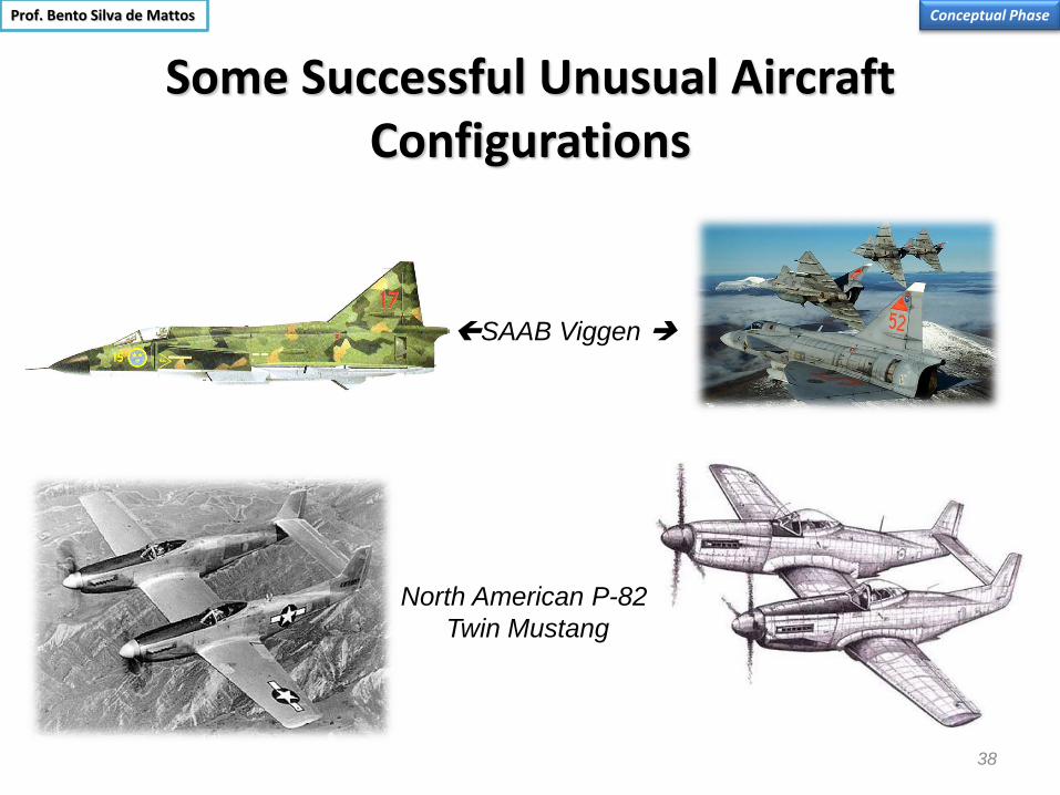
Some Successful Unusual Aircraft Configurations
SAAB Viggen
North American P-82
Twin Mustang
Conceptual Phase Prof. Bento Silva de Mattos

39
Some Unsuccessful Aircraft Configurations: Budd Conestoga
When the U.S. entered World War II in December 1941, there were concerns whether American industry could produce the
huge quantity of materials needed to fight the war. One of the main concerns was whether the vast amounts of aluminum
needed for aircraft would be available.
The Edward G. Budd Manufacturing Company of Philadelphia, Pennsylvania, the manufacturer of munitions and railroad rolling
stock, approached the U.S. Navy (USN) with a proposal to build a twin-engined cargo aircraft comparable to the Douglas R4D,
q.v., but made of stainless steel. The USN accepted the proposal and placed an order for 200 RB-1's in August 1942; the U.S.
Army Air Forces (USAAF) also became interested and placed an order for 600 aircraft, designated C-93A-BU,
The RB-1 was a twin-engined high-wing monoplane with tricycle landing gear and 24-volt electrical system powered by 1,200
hp (894.8 kW) Pratt & Whitney R-1830-92 14-cylinder, twin-row, air-cooled, radial engines driving three-bladed Hamilton-
Standard Hydromatic constant-speed, full-feathering propellers. The rear of the outer portion of the wing, i.e., from the engine
nacelle to the wingtip, and the elevators and rudder were fabric covered. The fuselage featured a bulbous nose enclosing an
elevated flight deck. The elevated flight deck permitted the cargo area to be unobstructed for its entire length.
The first flight of the RB-1 occurred on 31 October 1943 and this aircraft was delivered to the USN in March 1944. It crashed
during testing and the test pilot swore that the plane's stainless steel construction saved his life. The flying characteristics of the
RB-1 were poor and problems with the use of stainless steel developed delaying production and causing the price to rise.
These difficulties plus the adequate supply of aluminum and the availability of the C-47/R4D resulted in the USAAF canceling
their order for this aircraft and the USN reducing their order from 200 to a total of 26.
Feasibility Study Prof. Bento S. de Mattos

Ugly is Most of Time not Good
Introduction

41
Designed by a Flight Enthusiast
Introduction
Prof. Bento Silva de Mattos
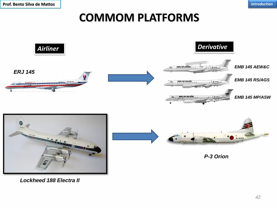
COMMOM PLATFORMS
42
Derivative Airliner
ERJ 145
Lockheed 188 Electra II
P-3 Orion
EMB 145 MP/ASW
EMB 145 AEW&C
EMB 145 RS/AGS
Introduction Prof. Bento Silva de Mattos

43
Embraer EMB-110 variants and Derivatives
Fonte: Revista Manche, 1978
Introduction Prof. Bento Silva de Mattos Derivative
Military Transport

EMB-110 Bandeirante Version (Designation by FAB) EIS Role
EMB-110 (C-95) 1973 Military liaison
EMB-110A (EC-95) 1973 Aerial Laboratory (Calibration of Airport Instrumentation)
EMB-110B 1975 Aerial photography
EMB-110C 1973 Airliner (15 passengers)
EMB-110E/J 1975 Executive transport
(7-8 passengers)
EMB-110P 1975 Regional airliner
(18 pax)
EMB-110S1 1976 Remote sensing
EMB-110B1 1976 Conversível Passageiros/Aerofotogrametria
EMB-110K1 (C-95A) 1977 Cargo/Paratroops transport
EMB-110P2 1977 Regional Airliner
(21 pax)
EMB-111 1977 Patrolling
EMB-110P1 1978 Transporte de Passageiros e Carga (19 pax)
Introduction

EMB-100/100A
O EMB-100 Bandeirante foi desenvolvido no Centro Técnico de Aeronáutica (Atualmente Comando-Geral de Tecnologia Aeroespacial) a partir de 1965 (Programa IPD-6504) por uma equipe liderada por Osires Silva que também envolveu o francês Max Holste. Inspirado no Nord 262 desenvolvido inicialmente por Holste, o Bandeirante realizou o seu primeiro vôo em 1968. Foi o primeiro bimotor metálico projetado e construído no Brasil e a Embraer foi criada para produzí-lo em série. O EMB-100 serviu de plataforma para o EMB-110C (derivado do EMB-110 da FAB), o primeiro modelo civil que de fato foi comercializado pela Embraer. Vale ressaltar, que o terceiro protótipo foi fabricado após a criação da Embraer, equipado para ser um laboratório voador para pesquisas com sensoriamento remoto.
Informações Técnicas Unidades fabricadas: 3 Primeiro vôo: 22 de outubro de 1968 Capacidade: 2 tripulantes e 7, 9 ou 10 passageiros dependendo do protótipo Peso máximo de decolagem: 4500 kg Envergadura: 15,38 m Área da asa: 29,22 m2 Velocidade máxima de operação: 389 km/h Motor: Pratt&Whitney PT6-A20 de 550 shp
Bandeirante Introduction
Prof. Bento Silva de Mattos

EMB-110 A/B/C/E/F/K1/J/P/P1/P1A/P2/S1
O EMB-110 (C-95 da Força Aérea Brasileira, FAB) e o EMB-110C Bandeirante foram uma modificação substancial do EMB-100, que havia sido desenvolvido no CTA. Trem de pouso totalmente escamoteável, motores mais potentes, naceles dos motores redesenhadas, maior capacidade de passageiros com a fuselagem aumentada em quase dois metros foram algumas, entre várias outras, modificações levadas adiante pela recém criada Embraer. A Transbrasil foi o primeiro operador civil do Bandeirante, que lhe foram entregues em abril de 1973. Foi a primeira vez que uma cia. aérea nacional foi equipada com um produto de origem brasileira. A Embraer continou aperfeiçoando e desenvolvendo novas versões de seu bimotor. Em 1978, obteve a certificação do P1 e P2 no mercado norte-americano, onde o Bandeirante foi um sucesso de vendas. Por conta de sua versatilidade e facilidade de manutenção, cerca de 500 exemplares foram fabricados até maio de 1990, quando a produção foi encerrada. Na África do Sul, a robustez do modelo foi mais uma vez comprovada com a conversão do Bandeirante para operar como avião agrícola, conversão feita por operadores locais. A FAB em 2008 contava com 105 Bandeirantes, em 9 versões e duas variantes, que desempenham cinco missões distintas operando em 14 esquadrões, além de dotar vários outros como aeronave orgânica. Além das versões mais comuns de transporte C-95, C-95A, C-95B e C-95C, são utilizadas pela FAB duas versões para calibragem de instrumentos, EC-95B e EC-95C, duas variantes para patrulha marítima, P-95A e P-95B, uma versão para busca e salvamento, SC-95B, uma versão para pesquisa de chuvas, XC-95, e, finalmente, uma de reconhecimento e levantamento aerofotográfico, designada de R-95.
Informações Técnicas Planes manufactured: 501 Entry into service: 1973 with the Brazilian Air Force (FAB) Shut down of the assembly line: May 1990 Accomodation: 15 pax + 2 cockpit crew (EMB-110C) MTOW: 5600 kg (EMB-110C) MLW: 5300 kg VMO: 426 km/h (EMB-110C) Powerplant: Pratt&Whitney PT6 turboprop ranging from de 680 to 750 shp for the several versions and variants
Bandeirante Introduction

Bandeirante EMB-110C
Em 1972 o Bandeirante foi homologado pelo Centro Técnico de Aeronáutica (Atualmente Comando-Geral de Tecnologia Aeroespacial). O EMB-110C foi a versão derivado do EMB-110 (C-95 da FAB) que a Embraer desenvolveu como transporte básico de linha aérea (15 passageiros podeiam ser transportados). Através de apoio a aviação de terceiro nível, empresas nacionais como a Transbrasil, Rio–Sul , VASP e TAM vieram a adquirir o Bandeirante. Em 26 de janeiro de 1973, a Trannsbrasil formalizou a compra de seis Bandeirante. A Transbrasil foi também a primeira empresa aérea a receber o modelo, o que se deu 11 de abril de 1973. Na segunda metade de setembro de 1973, foi realizado em São José dos Campos o 1o Salão Aeroespacial Internacional, ocasião em que foi anunciada a venda de 10 Bandeirante para a VASP. Posteriormente, os Bandeiantes da Transbrasil foram repassados à Nordeste Linhas Aéreas e os da VASP à TAM. Cinco exemplares foram fronecidos à Força Aérea do Uruguai. O EMB-110C(N) diferia bo EMB-110C pela instalação de equipamentos de degelo nas asas, hélices, empenagem, entrada de ar dos motores e pára-brisa.
Informações Técnicas Delivered: 37 planes Certified by CTA: December 20, 1972 Service entry: April 16, 1973 Accommodation: 15 pax + 2 cockpit crew Wingspan: 15,3 m Length: 14,2 m MTOW: 5600 kg MLW: 5300 kg Service ceiling: 8660 m Max. speed: 426 km/h Powerplant: Pratt&Whitney PT6-A27 de 680 shp
Introduction

Bandeirante EMB-110K1 (C-95A)
Concebido para operar com cargueiro militar, é utilizado também no transporte de pára-quedistas. O EMB-110K1 teve a sua fuselagem alongada em 0,85 em relação ao EMB-110 (C-95). Nesta versão, os tripulantes têm acesso direto à cabina de comando, sem passar pela fuselagem central, já que no lado esquerdo ao posto de pilotagem foi instalado uma porta de tripulantes (0,63 x 1,42 m). No lado direito, há uma porta de emrgência para os tripulantes. A fuselagem central dispõe de um volume útil de 14,7 m3. O piso foi reforçado, podendo suportar uma carga de 488 kg/m2. A porta principal da fuselagem foi alargada em relação ao C-95, passando a ter 1,80 m de largura por 1,42 m de altura. Ela é atuada hidraulicamente por meio de bomba manual. Nesta porta, foi incorporada um porta menor, que se abre para o interior da fuselagem e que serve como porta de emrgência,embora a sua finalidade principal é a de permitir o salto de pára-quedistas. O avião pode receber assentos laterais para a comodação de até 20 pára-quedistas.
Informações Técnicas Entry into service: 1978 Accommodation: 2 pilots + MTOW: 5600 kg MLW: 5300 kg Service ceiling: 7.620 m VMO: 426 km/h Powerplant: 750-shp Pratt&Whitney PT6-A34d turboprop

EMB-110P1/P1A/P2
Visualmente, o EMB-110P1 se destaca pela larga porta de carga na traseira da aeronave e pelo diedro de 10 graus na empenagem horizontal para livrá-la da esteira da asa e do motor. Operava tanto como versão cargueira como de passageiros, quando admitia até 18 assentos. Foi a versão que junto com a P2 (sem diedro na empenagem horizontal) foi homologada pela norte-americana Agência Federal de Aviação (FAA, “Federal Aviation Administration”) em 1978, o mesmo ano que o Congresso daquele país desregulamentou o mercado de aviação, permitindo um crescimento expressivo da aviação regional. Assim, o Bandeirante se tornou também um sucesso de vendas nos Estados Unidos.
Informações Técnicas (P1A) Entrada em serviço: 1978 (P1) Homologação CTA: 9 de maio de 1978 Capacidade: 19 passageiros + 2 tripulantes Peso máximo de decolagem: 5.670 kg Peso máximo de pouso: 5.450 kg Teto de serviço: 7.620 m Velocidade máxima de operação: 426 km/h Capacidade de combustível: 1.896 litros Motor: Pratt&Whitney PT6-A34 de 750 shp
Bandeirante
At left . EMB-110P1
passenger cabin
Above. EMB-110P2
Above . EMB-110P1

EMB-111 Bandeirulha
O EMB-111 é uma versão de patrulha marítima do Bandeirante. Era dotado de um radar de busca no nariz do aparelho, faróis, tanques de ponta de asa (os mesmos do EMB-326GB Xavante) e de foguetes não-guiados SBAT 70/7. A Força Aérea Brasileira recebeu um primeiro lote de 12 unidades (P-95) entre 1977 e 1979. Um segundo lote de 8 aviões de uma versão aperfeiçoada (P-95B) foram comprados em fins de 1989. As principais diferenças se referiam ao diedro da empenagem horizontal e a aviônicos mais modernos. A Argentina utilizou o EMB-111 durante a Guerra das Malvinas em 1982.
Informações Técnicas Entrada em serviço: 1977 com a Força Aérea Brasileira Capacidade: 15 passageiros + 2 tripulantes Peso máximo de decolagem: 7.000 kg Peso vazio: 5150 kg Velocidade máxima: 385 km/h Alcance máximo: 3.250 km Envergadura: 15,95 m Grupo motopropulsor: Pratt&Whitney PT6-A34 de 750 shp Operadores: Brasil, Argentina, Chile e Gabão
Bandeirante

COMMOM PLATFORMS
Airliner Military Plane
Boeing’s Heavy Lifter Concept Boeing 747-100
Introduction
In 1963, the United States Air Force started a series of study projects on a very large "strategic" transport aircraft. Although the
C-141 Starlifter was being introduced, they felt that a much larger and more capable aircraft was needed, especially the
capability to carry "outsized" cargo that would not fit in any existing aircraft. These studies led to initial requirements for the CX-
Heavy Logistics System (CX-HLS) in March 1964 for an aircraft with a load capacity of 180,000 pounds (81,600 kg) and a
speed of Mach 0.75 (500 mph/805 km/h), and an unrefueled range of 5,000 nautical miles (9,260 km) with a payload of
115,000 pounds (52,200 kg). The payload bay had to be 17 feet (5.18 m) wide by 13.5 feet (4.11 m) high and 100 feet (30.5 m)
long with access through doors at the front and rear.
Featuring only four engines, the design also required new engine designs with greatly increased power and better fuel
economy. On 18 May 1964, airframe proposals arrived from Boeing, Douglas, General Dynamics, Lockheed and Martin
Marietta; while engine proposals were submitted by General Electric, Curtiss-Wright, and Pratt & Whitney. After a downselect,
Boeing, Douglas and Lockheed were given additional study contracts for the airframe, along with General Electric and Pratt &
Whitney for the engines.
All three of the airframe proposals shared a number of features, but one in particular would become iconic on the 747. As the
CX-HLS needed to be able to be loaded from the front, a door had to be included where the cockpit usually was. All of the
companies solved this problem by moving the cockpit to above the cargo area; Douglas had a small "pod" just forward and
above the wing, Lockheed used a long "spine" running the length of the aircraft with the wing spar passing through it, while
Boeing blended the two, with a longer pod that ran from just behind the nose to just behind the wing. In 1965 Lockheed's
aircraft design and General Electric's engine design were selected for the new C-5 Galaxy transport, which was the largest
military aircraft in the world at the time.
Prof. Bento Silva de Mattos

Seaplanes Introduction
Prof. Bento Silva de Mattos

Seaplanes
Introduction
The Saunders-Roe Princess was a British
flying boat aircraft built by Saunders-Roe,
based in Cowes on the Isle of Wight. The
Princess was one of the largest aircraft in
existence.
By the 1950s, large, commercial flying boats
were being overshadowed by land-based
aircraft. Factors such as runway and airport
improvements added to the viability of land-
based aircraft, which did not have the weight
and drag of the boat hulls on seaplanes nor the
issues with seawater corrosion.
Prof. Bento Silva de Mattos

54
World War II Night Fighters
Introduction

55
Early VTOL Aircraft
Introduction Prof. Bento Silva de Mattos

56
Modern VTOL Aircraft
Introduction
U.S. Marine Corps MV-22B Osprey British Royal Navy FRS.Mk 1 Sea Harrier
Lockheed Martin F-35B Lightning II short
takeoff/vertical landing (STOVL) stealth fighter
Prof. Bento Silva de Mattos

Airworthiness Regulations & Certification
Introduction Prof. Bento Silva de Mattos

Structural Parts: Wing
• Wing box
• Fixed leading edge
• Fixed trailing edge
• Ailerons
• Spoilers
• Flaps
• Slats
Introduction
The structural concept for the wing is that part of the
airplane is essentially a beam which gathers and
transmits all the loads to the central fuselage attachment
Prof. Bento Silva de Mattos

Structural Parts: Wing
• Wing structure consists of – Internal structure
• Spars
• Ribs
• Stringers
– External structure • Upper skin
• Lower skin
• Wing structure should posses – Sufficient strength
– Stiffness
– Light weight
– Minimum manufacturing problems
Introduction
Prof. Bento Silva de Mattos

Structural Parts: Wing box • Front spar
• Rear spar
• Ribs
• Stringers
• Span wise beam
• Fuel tank
• Wing skins
Stringers
Prof. Bento Silva de Mattos Introduction
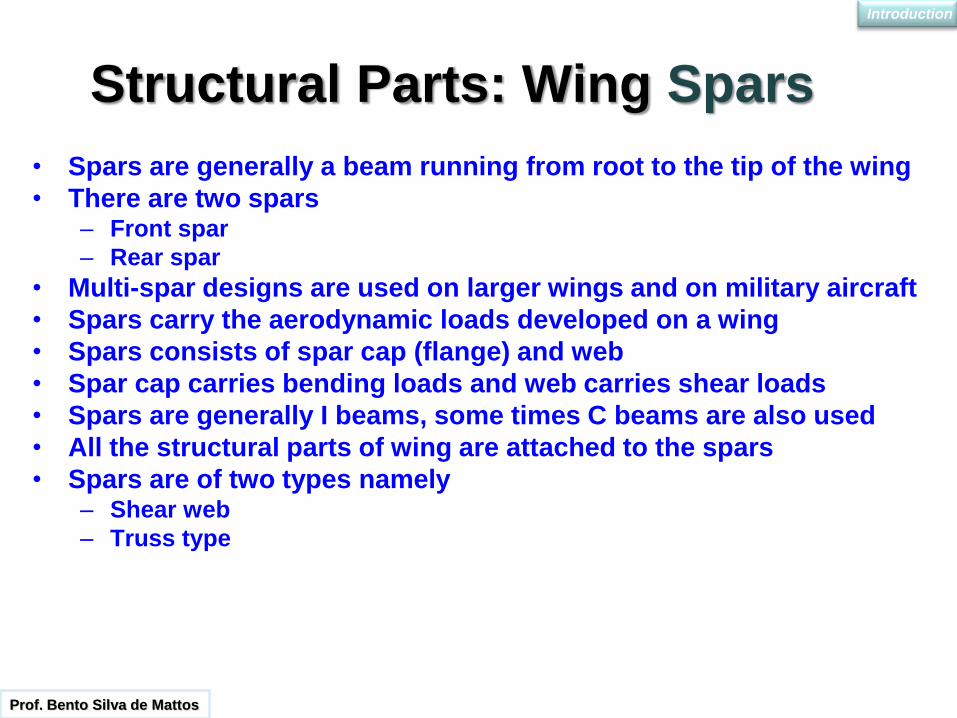
• Spars are generally a beam running from root to the tip of the wing
• There are two spars – Front spar
– Rear spar
• Multi-spar designs are used on larger wings and on military aircraft
• Spars carry the aerodynamic loads developed on a wing
• Spars consists of spar cap (flange) and web
• Spar cap carries bending loads and web carries shear loads
• Spars are generally I beams, some times C beams are also used
• All the structural parts of wing are attached to the spars
• Spars are of two types namely – Shear web
– Truss type
Structural Parts: Wing Spars
Introduction
Prof. Bento Silva de Mattos

TYPES OF SPAR
a) Built up spar
b) Truss type
c) Bent up channel
d) Frame truss
e) Sine wave web
f) Integrally machined
web
g) Integrally machined
truss
Introduction

SPAN WISE BEAMS
• Span wise beams are members in the wing which run from root to the tip
• Span wise beams are provided for additional support as well as to support the fuel tank
Introduction

Structural Parts: Fuselage

FUSELAGE ASSEMBLAGE
Prof. Bento Silva de Mattos
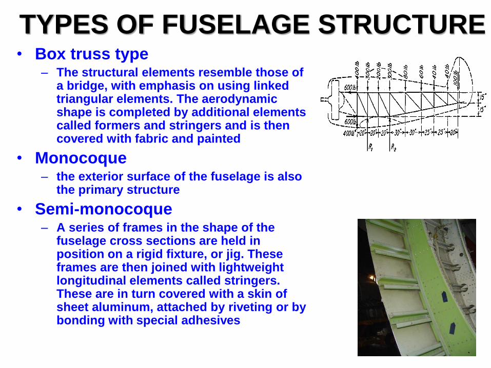
• Box truss type – The structural elements resemble those of
a bridge, with emphasis on using linked triangular elements. The aerodynamic shape is completed by additional elements called formers and stringers and is then covered with fabric and painted
• Monocoque – the exterior surface of the fuselage is also
the primary structure
• Semi-monocoque – A series of frames in the shape of the
fuselage cross sections are held in position on a rigid fixture, or jig. These frames are then joined with lightweight longitudinal elements called stringers. These are in turn covered with a skin of sheet aluminum, attached by riveting or by bonding with special adhesives
TYPES OF FUSELAGE STRUCTURE

Semi-monocoque fuselage structure consists of • Longerons / stringers (Longitudinal members)
Longerons carries the bending load as axial load
Stringers also carry axial load
Stringers stabilize the skin
• Framing (Transverse members) Provide the shape to the fuselage
Reduce the stringer length thus avoiding overall instability
• Skin Carries the shear load from the cabin pressure, external
transverse and torsional loads
• Bulkheads Bulkheads are provided at concentrated loading regions
such as wing attachments, tail attachments and landing gear locations
SEMI-MONOCOQUE FUSELAGE

SEMI-MONOCOQUE FUSELAGE

Airbus A340 Fuselage Structure
Multi-layer skin

70
Cutaway: British High-Wing Airliner BAe146-200
Air brake
Front spar
Rear spar
Introduction
Why a four-engined configuration was chosen for this plane?
Prof. Bento Silva de Mattos

Cutaway of a Supersonic Carrier-based Fighter Boeing F-18
• Folding Wings
• BWB
• Multi-spar wing structure
• Leading-edge snag
• Full movable horizontal tail
• Air-refueling probe
Introduction
Prof. Bento Silva de Mattos

Flight Envelope Supersonic Airplane
Introduction
Prof. Bento Silva de Mattos
The left-hand side of the figure marks
the speed at any height below which
there is insufficient lift to fly straight and
level. The dip in the curve around Mach
1 is caused by the increased drag and
a decrease in aerodynamic and
propulsive efficiency. Some airplanes
exhibit this characteristic to a marked
extent, others hardly at all. The top of
the curve marks the region where the
minimum level speed coincides with the
maximum speed that can be attained
with the particular combination of
engine and airframe. The right-hand
side of the curve represents the
propulsive limit, and the structural
limits: where higher speed, kinetic
heating and higher dynamic pressure
would require an excessively strong
and heavy airframe.

Typical Technical Tasks in the Aircraft Development Process
73
Flight Tests planning
Manufacturing plant
Tooling and machinery for manufacturing
Drawings
Evaluation of some different concepts to fulfill the requirements
Business opportunities study
Product specification document
Aircraft certification
Introduction
In order to keep pace with lower risks
– Project is divided into phases
– Scheduled reviews
– Suppliers become partners
– Advanced engineering tools like CFD and MDO
– Market studies
– Launching customer
– Manufacturing of some prototypes
– Technology certification by technology demonstrators, laboratories, joint ventures, cooperation efforts with he academic community
74
Introduction

Revisões de Passagem de Fase de Projeto -REFAPs
•As Revisões de Fase do Projeto devem ser conduzidas com muito critério, tanto em relação aos participantes quanto em relação à periodicidade. São eficientes quando há pessoas certas - contribuição.
75
• Os principais objetivos dessas avaliações periódicas são:
• Devem ser focadas e baseadas nos “deliverables” definidos na fase de planejamento.
Tomar as ações corretivas para reconduzir o projeto ao seu rumo original.
Determinar se os objetivos originais ainda são válidos.
Determinar se os requisitos iniciais do projeto estão sendo atendidos.
Determinar se há condição totais ou parciais para passar à Fase seguinte.
Introduction

Revisões de Passagem de Fase de Projeto -REFAPs (2)
• Entre as REFAPs há três que se destacam: Conceptual Design Review Preliminar Design Review Critical Design Review
76
•Elas são marcos do: congelamento da configuração do produto; da definição do produto; e da liberação à fabricação, respectivamente.
•Há muitas outras Revisões intermediárias que acontecem segundo às necessidades de cada produto. Também, são repetidas para diversas partes diferentes do avião.

Aircraft Design Phases
77
Feasibility
study
Conceptual design
(Initial Definition)
Preliminary design
(Joint Definition)
Detailed Design
Production
• There is classic phases in aircraft development program:
0 1 2 3 4 5
Phase Out
~10 years Customer support
Introduction

Other Approach
78
Feasibility Study
Preliminary design
Projeto Detalhado
Protótipos/ Qualificação/
Certificação Production Phase Out
0 1 2 3 4 5
É comum encontrar, em publicações e nas divisões de outras empresas aeronáuticas, as Fases 1 e 2 reunidas como Preliminar, somente. Ou acrescentar uma de Qualificação/Certificação, ficando assim:
Feasibility
Study
Conceptual
design
Projeto de
Definição
Projeto Detalhado (Protótipos
Certificação)
Production Phase Out
0 1 2 4 5
Uma melhor forma de se definir as fases de um Projeto são como segue
3
Introduction
79
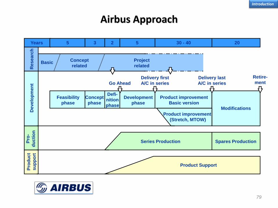
Years 5 3 2 5 30 - 40 20
Pro
du
ct
su
pp
ort
Product Support
Pro
-
du
cti
on
Series Production Spares Production
Basic Concept
related
Project
related Re
se
arc
h
Deve
lop
me
nt
Feasibility
phase
Concept
phase
Defi-
nition
phase
Development
phase
Product improvement
Basic version
Product improvement
(Stretch, MTOW)
Modifications
Retire-
ment Delivery last
A/C in series
Delivery first
A/C in series Go Ahead
Airbus Approach
Introduction

Description of the Aircraft Development Phases
Introduction
Phase Activities Focus
Feasibility study Market analysis; business
plan; technology assessment
Financing
Conceptual
Costs; performance; first wind-tunnel tests; CFD; MDO; layout of aircraft systems; partner and
supplier selection
Aircraft configuration selection; sizing; engine
selection
Preliminary design (JDP) System integration; mitigation of critical
engineering problems;
Complete aircraft definition
Detailed design Construction of
prototypes ; drawings; rigs; flight tests
Certification
Production
Production; preparation for entry into service;
production plan; quality control
Manufacturing, production rate
Operating life and phase out
Certification of maintenance shops;
service bulletins; fatigue life
Customer support/Recycling
Prof. Bento Silva de Mattos
Feasibility Study

82
Feasibility Study

Scope
83
•Market Analysis Trends and market dynamics Market Share Competitor aircraft database Competitive advantages Customer database Competitors menace
•Customer needs
Feasibility Study
•Business opportunities
Prof. Bento Silva de Mattos

Phase 0 Characteristics
84
• Althoug this phase is the first one, it is vital for the sucessful outcome of the aircraft program
• É dela que emanam a maioria das diretrizes: as estratégicas; as financeiras; e as de caracterização do produto.
•Esta Fase deve indicar se o projeto é viável, bem como avaliar todos seus riscos, para determinar o seu prosseguimento ou não.
Feasibility Study

Summary
Description of the company
Market analysis
Business financial parameters
Marketing strategy
Product development plan
Production scheme (requerido pelo órgão homologador)
Project management plan
Master Phase Plan
Risk assessment
Financial analysis
Capital amassment
Business Plan Feasibility Study

Product Development Process
Marketing Requirements & Objectives
• It all begins with … a potential need in the market • Identified through client comments, competitive and market analysis, market surveys …
• Important document : Marketing Requirements & Objectives •It covers different aspects, i.e. technical, operating cost, comfort, etc.
•The MR&O does not necessarily need to be comprehensive initially
•Written through use of surveys, focus groups
•• Getting the MR&O wrong may produce a devastating financial result for the company
•The requirements directly influence the function and form of the vehicle
Embraer CBA-123 Dassault Mercure SAAB 2000
See what
happens when
you do not get
the requirements
right!
Feasibility Study
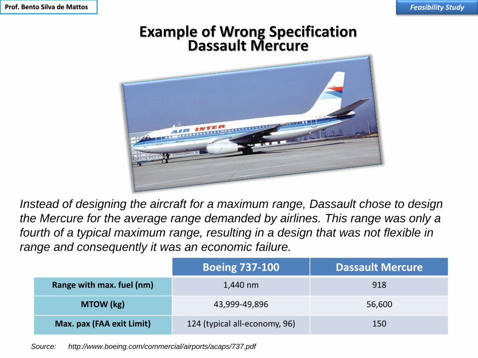
Example of Wrong Specification Dassault Mercure
Feasibility Study
Instead of designing the aircraft for a maximum range, Dassault chose to design
the Mercure for the average range demanded by airlines. This range was only a
fourth of a typical maximum range, resulting in a design that was not flexible in
range and consequently it was an economic failure.
Boeing 737-100 Dassault Mercure
Range with max. fuel (nm) 1,440 nm 918
MTOW (kg) 43,999-49,896 56,600
Max. pax (FAA exit Limit) 124 (typical all-economy, 96) 150
http://www.boeing.com/commercial/airports/acaps/737.pdf Source:
Prof. Bento Silva de Mattos

88
Program Failure: Beechcraft Starship
Feasibility Study
The Beechcraft Starship is a turboprop-powered
six- to eight-passenger seat business aircraft. The
design was originated by Beechcraft in January
1980 as Preliminary Design 330 (PD 330). Burt
Rutan was subsequently retained to refine PD330
and one of the significant changes he instituted
was the addition of variable geometry to the
canard (he holds a patent for this). Rutan's
California-based design and fabrication company
Scaled Composites was then contracted to build
scale-model prototypes to aid in development.
The Starship featured a carbon-composite
construction, unique design and rearward-facing
turboprop engines, which leased him a futuristic
look. But it was slow, difficult to fly and a bear to
maintain. A 85% scaled model performed its
maiden flight in 1983 and later three full-scale
prototypes were built. Beechcraft was able to sold
only sold a few of the 53 it built. The company
established a buy back program for the
exemplars that were sold but some owners
decided to keep the airplanes.

Program Failure: Sonic Cruiser
Conceptual Phase
Early in 2001 the Boeing company announced a new aircraft, the “Sonic Cruiser”. The most
impressive features of this new project were a range of up to 10,000 nm, a cruise Mach number
above M = 0.95 and the claim of a large reduction in flight time. A concept level study was
undertaken to design and analyze a possible aircraft configuration. One result of the study is the
fact, that the reduction of flight time by increasing the cruise Mach number to number of
Mach 0.98 is relatively small. A larger reduction of travel time seems to be possible only by using
direct point to point services instead of hub and spoke connections. Another result is, that the
claimed range would be very hard to reach.
Prof. Bento S. de Mattos

Case Study : Sonic Cruiser Configuration
Conceptual Phase
Mainly based on Boeings artists impressions and some published technical data like
approximate wing span, fuselage length and diameter it was possible to create a first design
sketch of the aircraft. The characteristic canard configuration with engines buried in the wing
and twin fins used for the analysis is shown in figure below. For the redesign a small capacity of
about 200 passengers has been assumed which seems to make sense for a point to point
connection concept.

Program Failure: Sonic Cruiser Fuselage
Conceptual Phase
Initially, a streamlined non-cylindrical cross section was selected for the sonic cruise in order to keep the transonic drag low.
Later, the center portion of the fuselage was replaced by a cylindrical part with a smooth transition between the cabin part and
the cockpit area respectively the tail cone to keep wave drag low.
The diameter of the cabin has been kept at a minimum which allows for a twin aisle 2-2-2 or 2-3-2 seating arrangement . The
diameter was chosen so, that it possible to carry two typical LD-3 containers side by side which requires a minimum diameter of
5.1 meters. Seating could be arranged so that 25 first class seats are available and the remaining seats can be used for a mixed
business / economy class seat arrangement as needed. Boarding would be behind the canard, with the main entrance/exit
separating first class and business class. The placement of emergency exits according to FAR guidelines poses no problems, but
all rear exits will be located over the inboard wing.
In order to avoid velocity peaks in the cockpit area, the flat windscreen windows have been aligned with the fuselage body as far
as possible. To ensure the required visibility angles, the windows would have to be larger than usual.
The canard wing was mounted high to achieve enough cabin height to access the first class compartment and the cockpit area.
The dihedral of the canard was initially copied from the publications and would help to avoid collision with ground equipment. On
the other hand it is not possible to establish sufficient lateral stability with the large angle of dihedral and the small tail fins so that
we can assume a small dihedral close to zero degrees.
From a structural point of view, the fuselage must sustain the somewhat higher pressure differential due to the increased flight
altitude and it must provide enough stiffness to carry the loads of the canard wing. The inboard wing extensions may provide
additional stiffness to the fuselage and can carry a large portion of the fuel.

Case Study: Ultra Long-range Business Jet
Bombardier Global Express XRS
Average completion costs US$ 10 million and custom ones even more.
It takes eight to 10 months to complete an aircraft and custom completions can take longer.
Most operators fly the aircraft 250-450 hours per year.
Most operator also say that they typically fly two or three people in transoceanic trips .
Bombardier projected a 51,200 lb BOW for the type. Operators say that it is a low-estimate for the airplane. According to them typical BOW lies in the range 52,000-54,000 lb because of optional cabin entertainment system.
The XRS is certified to flight to 51,000 ft, but most operators seldom climb above the mid forties.
Source: Business & Commercial Aviation, March 2010
Prof. Bento S. de Mattos

93
Case Study: Chance-Vought Corsair
Originally designed as a carrier-capable fighter, it saw combat in Guadalcanal in 1943 as land-based fighter instead.
It was fitted with a single 2000-hp powerful engine. This required large propellers in order to obtain higher efficiency
from this large amount of power. The 18-cylinder Pratt & Whitney R-2800 Double Wasp radial was the largest engine
available at the time.
An inverted gull wing, a similar layout to the one used by Germany's Junkers Ju 87 dive bomber, provided to the F4U
Corsair fighter a considerably shortened length of the main gear legs.
Its long nose was the origin for poor visibility from the cockpit. This caused accidents at carrier operations.
The large fuselage panels were made of magnesium and were attached to the frames with the newly-developed
technique of spot welding, thus mostly eliminating the use of rivets.
The combination of an aft cockpit and the Corsair's long nose made landings hazardous for newly-trained pilots.
During landing approaches it was found that oil from the hydraulic cowl flaps could spatter onto the windscreen, badly
reducing visibility, and the undercarriage oleo struts had bad rebound characteristics on landing, allowing the aircraft to
bounce out of control down the carrier deck.
The longest production run of any piston-engined fighter in U.S. history (1942–1952).
Feasibility Study Prof. Bento S. de Mattos

Case Study: Mitsubishi A6M Zero
Airframe was divided for manufacturing into two integral blocks (lower weight longer range and
higher maneuverability).
Although the airframe was of complex manufacture, over 10,000 Zeros left their respective
assembly lines.
The Zero was the first carrier-based fighter to outperform the land-based ones.
Lack of adequate armor resulted in loss of experienced pilots.
Most of the aircraft was built of T-7178 aluminum, a top-secret aluminum alloy developed by the
Japanese just for this aircraft.
Initially equipped with a 780-hp engine, in later versions power was increased to 1,130 hp.
Outperformed by the Grumman Hellcat fighter, Wildcat’s successor.
As Allied fighter design continually improved, the A6M would basically stay as the design first
conceived in 1937.
Feasibility Study
Prof. Bento Silva de Mattos

95
Case Study: North American P-51 Mustang
Designed to fulfill a British specification for the Spitfire replacement
Prototype flew just 119 days after program start
Laminar airfoils were selected to compose the wing geometry
After the Allison engine was replaced by the Rolls-Royce Merlin the P-51 fighter became
the outstanding fighter that everyone knows
Laminar flow can not be attained in practice due to manufacturing imperfections of the
aircraft surface and to accumulated dust and bugs on some parts of the airframe
exposed to airflow
It is believed that the P-51 Mustang fighter shot down half of German aircraft in World War II
Feasibility Study

96
Case Study: Convair 990
Conceived to fly at higher speeds than that of competition (Mach 0.92).
Although the commercial guideline to fly at high speed was wrong, the aircraft was
engineered to achieve this goal (Kücheman carrots at wings).
Later reengined with GE CJ-825-23 turbofans (fans placed at rear portion of the engine).
The engine was a simplified, non afterburning civilian version of the J79, used in military
fighters. Like the J79, the CJ805 was very smoky.
Lose the competition for Boeing 707 and Douglas DC-8.
Feasibility Study
General characteristics
•Crew: Four
•Capacity: 96 to 121 passengers
•Length: 139 ft 5 in (42.49 m)
•Wingspan: 120 ft (36.58 m)
•Height: 39 ft 6 in (11 m)
•Empty weight: 120,560 lb (54,690 kg)
•Powerplant: 4 × General Electric CJ805-23 turbofans, 16,100 lbf each
•Maximum speed: 534 knots (615 mph, 990 km/h) at 22,000 ft (6,095 m)
•Cruise speed: 495 knots (570 mph, 920 km/h) at 35,000 ft (10,667 m)
•Range: 4,700 nm (5,400 mi, 8,690 km)
•Service ceiling: 41,000 ft (12,496 m)
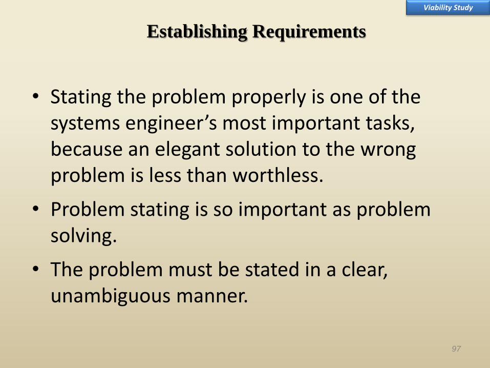
• Stating the problem properly is one of the systems engineer’s most important tasks, because an elegant solution to the wrong problem is less than worthless.
• Problem stating is so important as problem solving.
• The problem must be stated in a clear, unambiguous manner.
97
Establishing Requirements
Viability Study

The problem statement describes the customer’s needs, states the goals of the project, delineates the scope of the system, reports the concept of operations, describes the stakeholders, lists the deliverables and presents the key decisions that must be made.
98
Establishing Requirements
Viability Study
Prof. Bento Silva de Mattos

“Prevent the Germans from invading France through the Rhineland.”
According to this problem statement the, Maginot line was a success.
But with this problem statement
“Prevent the Germans from conquering France,”
The Maginot line was a failure. 99
Establishing Requirements
Feasibility Study

HLR- Customer Needs
100
Business plan Configuration
What
customers
need?
What we
can deliver?
Lean - Servir valores acima dos concorrentes.
How is the way to achieve the goals?
Negócios: qual mercado servir e como servir este mercado?
Feasibility Study

Market Analysis – Business Opportunities EMB 312 Tucano
Feasibility Study
The single-engined Embraer EMB 312 Tucano replaced expensive jets being
employed in the advanced trainer role. It was developed to address a Brazilian
Air Force procurement for the replacement of the Cessna AT-37 side-by-side
trainer. After the Cold War was over declining budgets for armed forces around
the world forced many countries to decommission costly jets used as trainers.
Prof. Bento Silva de Mattos

Market Analysis – Business Opportunities Sikorsky Skycrane, Special Purpose Helicopter
Feasibility Study Prof. Bento Silva de Mattos

Market Analysis – Business Opportunities Fokker 100 Reloaded
Feasibility Study
Entrepreneurs behind the long-running effort to develop a Fokker 100 successor intend to modify an existing airframe this
year, after securing financing from the Dutch economics ministry.
The organization driving the program, NG Aircraft, is a successor to the Rekkof company which has pressed for years to
restart Fokker production. NG Aircraft says that the economics ministry is to provide a €20 million ($27 million) loan -
although this still needs European Union clearance.
This funding would come through the Dutch SenterNovem agency, which became part of the ministry's innovations support
arm Agentschap NL this year.
SenterNovem has a civil aviation department which funds pre-competitive work, such as design, simulation and tooling, for
the creation of non-commercial prototype aircraft.
Grants of up to €10 million are available for aircraft transporting fewer than 100 passengers, or €20 million for other cases.
Under an initial phase NG Aircraft will begin adapting a Fokker 100 with new systems and engines. The twin-jet will serve as
a demonstrator for the proposed Fokker 100 NG, the first example of which the company wants to assemble by 2015.
Source: Flight Global, March 2010
Prof. Bento Silva de Mattos

Establishment of aircraft mission profile
Supersonic SSBJ
Viability Study

MTOW
(kg)
Range
(nm)
Mach
(max)Pax Crew
Cruise
Altitude (ft)
Valor de
Mercado US$
1.000,00
41051 6500 0,885 13-19 4 51000 (max) USS 41.550,00
41277 6750 0,885 13-19 4 51000 (max) USS 41.550,00
33838 4220 0,88 12-19 3 45000 (max) USS 32.750,00
20500 3769 0,85 9-19 3 41000 (max) US$ 21.800,00
24040 3120 0,8 14-19 3 41000 (max) USS 24.900,00
17010 3100 0,82 8-16 2 45000 (max) USS 14.700,00
43207 6010 0,88 8-19 2-4 51000 (max) USS 38.000,00
40032 4800 0,88 8-19 2-3 51000 (max) USS 32.950,00
7711 1455 0,81 6-7 2 51000 (max) USS 6.525,00
9412 2120 0,81 up to 9 2 51000 (max) USS 9.420,00
10659 2510 0,81 up to 10 2 51000 (max) USS 11.970,00
16375 3390 0,92 8-12 2 51000 (max) USS 18.600,00
4808 1474 0,7 5-7 2 41000 (max) USS 3.800,00
5670 1738 0,72 6-7 2 45000 (max) USS 4.300,00
16238 3000 0,87 8-19 2 47000 (max) USS 23.500,00
18461 3800 0,87 8-10 2 47000 (max) USS 32.000,00
ModelsEquipped Empty
Weight (lb)
Gulfstream V 48000
Gulfstream V-SP 48300
Gulfstream IV-SP 42500
Challenger 604 26630
Challenger SE 33900
Continental 22350
Global Express 50300
Global 5000 N/A
Learjet 31A 11140
Learjet 45 13550
Learjet 60 14640
Citation X 19376
Citation CJ1 6460
Citation CJ2 7359
Falcon 2000 20735
Falcon 2000EX 22330
Market Analysis – Comparing Competitors
Feasibility Study

Market Analysis – Comparing Competitors Feasibility Study
Source: Flight Global

Market Analysis – Comparing Competitors
Feasibility Study
Source: Embraer

Market Outlook Drivers
Feasibility Study
Source: Boeing

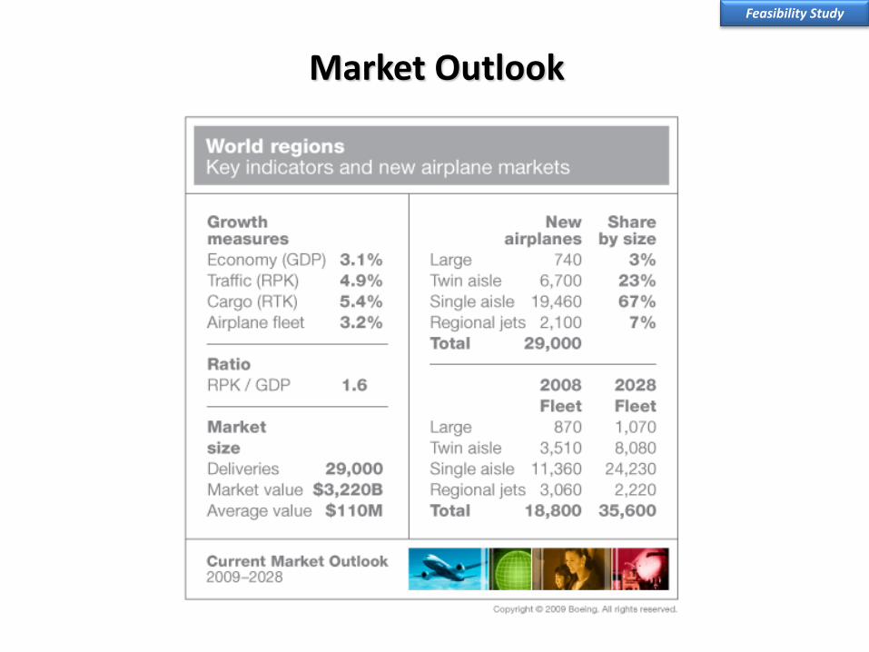
Market Outlook
Feasibility Study
Market Outlook
Feasibility Study

Market Outlook Feasibility Study
Source: Boeing

Market Outlook Feasibility Study
Source: Boeing

Market Outlook
Feasibility Study
Source: Boeing

Market Outlook
Feasibility Study
Source: Boeing
Market Outlook Feasibility Study
Source: Boeing
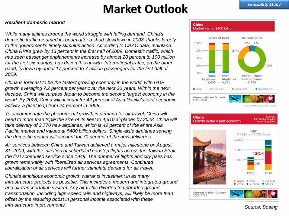
Resilient domestic market
While many airlines around the world struggle with falling demand, China's
domestic traffic resumed its boom after a short slowdown in 2008, thanks largely
to the government's timely stimulus action. According to CAAC data, mainland
China RPKs grew by 13 percent in the first half of 2009. Domestic traffic, which
has seen passenger enplanements increase by almost 20 percent to 100 million
for the first six months, has driven this growth. International traffic, on the other
hand, is down by about 17 percent to 7 million passengers for the first half of
2009.
China is forecast to be the fastest growing economy in the world, with GDP
growth averaging 7.2 percent per year over the next 20 years. Within the next
decade, China will surpass Japan to become the second largest economy in the
world. By 2028, China will account for 42 percent of Asia Pacific's total economic
activity, a giant leap from 24 percent in 2008.
To accommodate the phenomenal growth in demand for air travel, China will
need to more than triple the size of its fleet to 4,610 airplanes by 2028. China will
take delivery of 3,770 new airplanes, which is 42 percent of the entire Asia
Pacific market and valued at $400 billion dollars. Single-aisle airplanes serving
the domestic market will account for 70 percent of the new deliveries.
Air services between China and Taiwan achieved a major milestone on August
31, 2009, with the initiation of scheduled nonstop flights across the Taiwan Strait,
the first scheduled service since 1949. The number of flights and city pairs has
grown remarkably with liberalized air services agreements. Continued
liberalization of air services will further stimulate demand for air travel.
China's ambitious economic growth warrants investment in as many
infrastructure projects as possible. This includes a modern and integrated ground
and air transportation system. Any air traffic diverted to upgraded ground
transportation, including high-speed rails and highways, will likely be more than
offset by the resulting boost in personal income associated with these
infrastructure improvements.
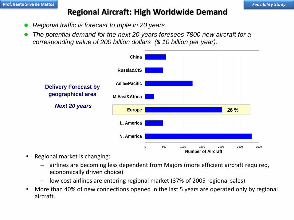
Regional Aircraft: High Worldwide Demand
• Regional market is changing:
– airlines are becoming less dependent from Majors (more efficient aircraft required, economically driven choice)
– low cost airlines are entering regional market (37% of 2005 regional sales)
• More than 40% of new connections opened in the last 5 years are operated only by regional aircraft.
Delivery Forecast by
geographical area
0 500 1000 1500 2000 2500 3000
N. America
L. America
Europe
M.East&Africa
Asia&Pacific
Russia&CIS
China
26 %
Number of Aircraft
Regional traffic is forecast to triple in 20 years.
The potential demand for the next 20 years foresees 7800 new aircraft for a corresponding value of 200 billion dollars ($ 10 billion per year).
Next 20 years
Feasibility Study Prof. Bento Silva de Mattos

Regional
Narrow Body
Wide Body
46%
46%
8%
Departures
Regional
Narrow Body
Wide Body
41%
45%
14%
Fleet
Regional
Narrow Body
Wide Body
29%
48%
23%
Flown Hours
8800 Units
correlated with
community noise
correlated with
gaseous
emissions
European regional fleet represents 20% of current worldwide regional fleet
Fully 60% of airports with scheduled service are served only by regional aircraft.
Regional Aircraft: Important Role in ATS
Sources: Alenia data processed from Lundkvist, Avsoft and Back-OAG databases
Total World - Year
2005
Feasibility Study Prof. Bento Silva de Mattos

Market Analysis
118
Maiores possibilidades de compras:
Low Cost Airlines
Quem compra Ex. 150-200 lugares
Feasibility Study Prof. Bento Silva de Mattos

Market Analysis
CRJ953 A/C ERJ
900 A/C
Do328 jet44 A/C
Hawker16 A/C
YAK-40222 A/C
0
50
100
150
200
250
300
350
Deliveri
es [
A/C
]
1993 1998 2003 2008 2013 2018 2023
Frota Atual
30 – 60 seater airliner
Feasibility Study Prof. Bento Silva de Mattos

120
• Problemas de Certificação – Atrasos no Lançamento
• Falta de Financiamento • Custo mais alto do que o Planejado
•Tamanho da Empresa
•Problemas Externos- Estabilidade Política/Financeira do País
• Riscos Identificados
• Plano de Ação para cada Risco
• Riscos Classificados
Resultados
Impacto
Pro
ba
bili
da
de
Riscos
Análise Típica
O Board da Empresa
tem que conhecer seus
pontos vulneráveis e se
preparar para superá-los
Feasibility Study: Risks Feasibility Study

Terms concerning Financial Analysis
121
•VPL-Valor Presente Liquido: é o valor onde é recuperado o investimento considerando as taxas de juros do mercado financeiro.
•Pay Back Time: é o tempo para recuperar o seu investimento sem juros de capital.
•Break Even Point: é a quantidade de vendas de aeronaves necessária à recuperação do investimento.
•TIR: é a taxa de desconto que iguala o valor presente das receitas com o valor do investimento inicial do projeto.
Feasibility Study

Investment Analysis
• Demand prediction: 10 years starting in 2013.
• Internal rate of return: 18%.
Feasibility Study Prof. Bento Silva de Mattos
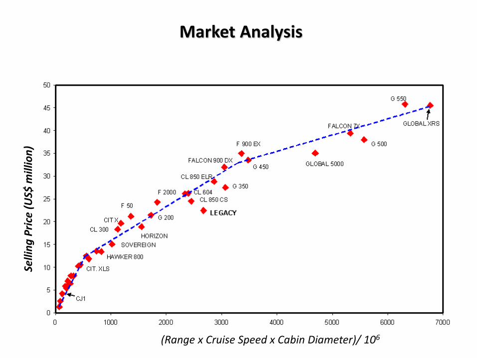
Market Analysis
(Range x Cruise Speed x Cabin Diameter)/ 106
Selli
ng
Pri
ce (
US$
mill
ion
)

Conceptual Phase (Estudo de Conceitos)

Detailed budget
Work Breakdown Structure (WBS)
Scope
Master Phase Plan
Quality
Rules, standards, and norms
Conceptual Phase

Scope (cont.)
126
Requirements shall be checked and improved
Aircraft sizing
Performance calculation (aerodynamic database).
Structual layout
Engine selection (supplier)
Wind-tunnel testing (wing planform and section geometry)
Aircraft Configuration
Preliminary safety assessment.
System layout and preliminary system integration
Conceptual Phase
Technical drawings
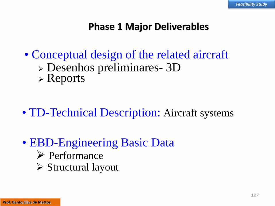
Phase 1 Major Deliverables
127
• Conceptual design of the related aircraft Desenhos preliminares- 3D Reports
• EBD-Engineering Basic Data Performance Structural layout
• TD-Technical Description: Aircraft systems
Feasibility Study
Prof. Bento Silva de Mattos
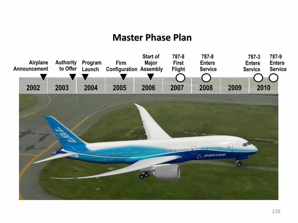
Master Phase Plan
128
2005 2002
787-8 First
Flight
787-8 Enters Service
Airplane Announcement
Firm Configuration
Program Launch
Authority to Offer
2003 2004 2006 2007 2008 2009 2010
787-3 Enters
Service
787-9 Enters Service
Start of Major
Assembly

High Level Requirements
129
• Ao final da extensa e crítica Fase 0 chega-se a um dos mais importantes Deliverables: o doc com a Missão da Aeronave e os HLR (High Level Requirements). São oriundos da Inteligência de Mercado e da área de Planejamento Estratégico da Empresa, profundamente trabalhados com o Anteprojeto.
• Nessa altura as grandes decisões estratégicas da caracterização do produto foram tomadas e elas influenciarão de maneira marcante o que vem pela frente, por exemplo:
Fly by wire
Materiais
Motorização
Nível Tecnológico
Conceito Família
Modernidade/Desafios

Conceptual Phase
Most important objectives from a conceptual design perspective are :
• Cabin/Baggage size: cross-section, length, volume & access
• Field performance: Balanced Field Length (BFL), Weight-Alt.-Temp.
(WAT), approach speed (VREF)
• En route performance: Initial Cruise Altitude (ICA), cruise speed(s),
buffet limits, range
• Keep BOW as low as possible to be competitive
• DOC goal must be achieved
• Others include block fuel, aft-body strike, derate schedule

Conceptual Phase

Conceptual Phase

133
Passenger Comfort
+
Field Performance
+
Range
+
Remained requirements
DOC
Best valued
product for the
market
Objectives vs. Aircraft Parameters
Conceptual Phase

Conceptual Phase

135
Morphology Selection
Conceptual Phase
• Morphology of an aircraft is the combination of wings, fuselage, landing gear,
empennage and power plant integrated to fulfill (as much as possible) the MR&O
• A myriad of configurations are available
•Selection of the configuration layout depends upon numerous factors:
-Mission role
-Economics
-Operational and functional requirements
-Safety and reliability
-Type of propulsion system
-Commonality with other variants/derivatives

136
Carrier-based AEW Platform Selection
Conceptual Phase

Fighter concepts developed by NASA for the F-15 mission requirements
Conceptual Phase
The wing planform of the variable-
sweep Grumman F-14 Tomcat. The
retractable vane reduces excessive
longitudinal stability with teh wings
fully swept back (from Loftin, NASA
SP 468, 1985)
Entire movable wing is not suited
Impact of Flight Dynamics on Configuration

138
Fighter concepts developed by NASA for the F-15 mission requirements
Conceptual Phase
LFAX-4—a variable-sweep configuration
LFAX-8— a fixed-sweep version of LFAX-4
LFAX-9—wing-mounted twin-engine
configuration
LFAX-10—similar in external shape to
Soviet MiG-25 Foxbat
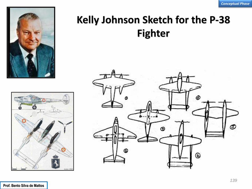
139
Kelly Johnson Sketch for the P-38 Fighter
Conceptual Phase
Prof. Bento Silva de Mattos

Commonality
• Much of focus in product family design is to improve commonality and standardization within the family
• What is commonality? – Possession of common features or attributes in either the product or
the manufacturing process for a set of products
• A product platform is defined “as the common elements, especially the underlying core technology, implemented across a range of products” (McGrath, 1995)
• Main advantage of commonality within a product family: – maintain economies of scale (and scope) in manufacturing and
production processes 140

Advantages of Commonality
• Decrease lead times (and risk) in product development
• Reduce product line complexity
• Reduce set-up and retooling time
• Fewer components in inventory
• Fewer parts need to be tested and qualified
Other advantages? 141
Conceptual Phase

142
Disadvantages of Commonality
• Lack of
distinctiveness
• Hinder innovation
and creativity
• Compromise
product
performance
Degree of Commonality
Best Designs
Poor Designs
Individually Optimized Designs
Perf
orm
ance
Designs Based on Common Platform
Despite disadvantages of commonality, it does provide a useful metric for assessing families of products.
Conceptual Phase

The 787 Family of Aircraft
143
787-8 210-250 passengers (three-class)
7,650 – 8,200 nm
787-9 250-290 passengers (three-class)
8,000 – 8,500 nm
787-3 290-330 passengers (two-class)
2,500 – 3,050 nm
Conceptual Phase
Prof. Bento Silva de Mattos

144
Embraer Aircraft Family
EMBRAER 190
EMBRAER 195
EMBRAER 170
EMBRAER 175
95% Commonality
85% Commonality
95% Commonality
Common pilot type rating
100% commonality in the cockpit
High level of commonality in system components
100% flying commonality due to fly-by-wire system
Conceptual Phase
Prof. Bento Silva de Mattos

145
Performance of the E-Jets
Conceptual Phase
Prof. Bento Silva de Mattos
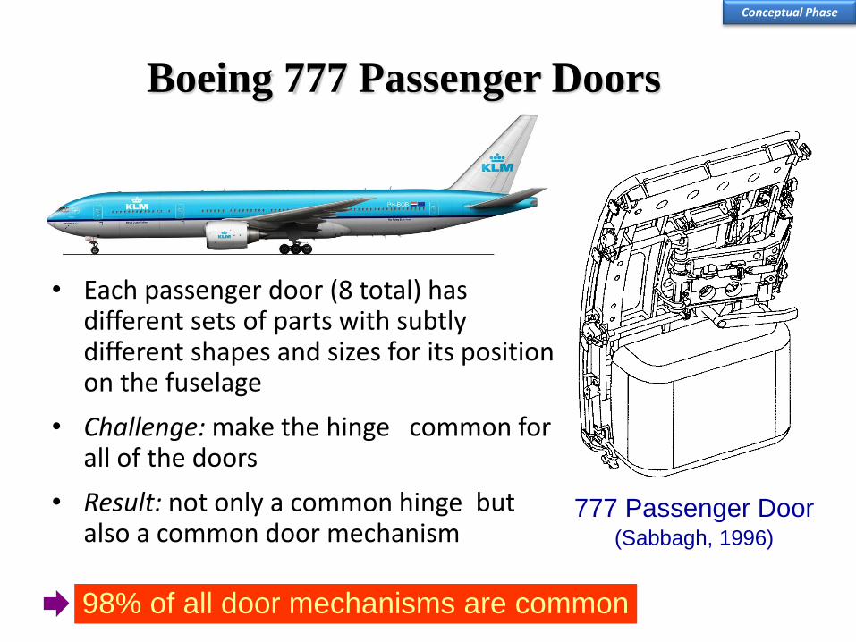
Boeing 777 Passenger Doors
• Each passenger door (8 total) has different sets of parts with subtly different shapes and sizes for its position on the fuselage
• Challenge: make the hinge common for all of the doors
• Result: not only a common hinge but also a common door mechanism
777 Passenger Door (Sabbagh, 1996)
98% of all door mechanisms are common
Conceptual Phase

147
Wing-Mounted or Fuselage-Mounted Engines?
Conceptual Phase
Prof. Bento Silva de Mattos

148
Wing-Mounted or Fuselage-Mounted Engines?
Wing Mounted
• More critical for flutter problems
• Prone to water spray ingestion
• Larger landing gear
• Enable eventually additional rear doors
• Engines alleviate bending moment
• Disturb the airflow over the wing
• Can easily be struck and damaged in a misjudged crosswind landing
• The length of fuel lines minimized
• May limit the flap span
• Less available fuel volume for wing mounted engines because dry bays in the wing fuel tanks
to cater for disc bursts are required
Conceptual Phase
Prof. Bento Silva de Mattos

149
Wing-Mounted or Fuselage-Mounted Engines?
Rear Mounted
• May suffer from boundary layer ingestion
• Bleed air supply more complicated
• Difficult to inspect by the crew and maintenance team
• Thrust line above the cg
• Critical for stretched versions
• Larger tailplane
• Lower cabin noise level
• Rear mounted engines often require soft (rubber/fluid) engine mounts to absorb vibration and blade
off loads. For wing mounted engines the flexible wings act as effective dampers thus
allowing engines to use cheaper hard mount arrangements
• Heavier aft fuselage structure
• Ice shed from the wing and aircraft nose can be ingested by the engine
• There is the possibility of high drag from the convergent/divergent channel formed between the
nacelle and the fuselage wall on rear mounted engine installations
• Aft fuselage mounted engines reduce the rolling moment of inertia. This can be a disadvantage if
there is significant rolling moment created by asymmetric stalling. The result can be an
excessive roll rate at the stall
Conceptual Phase
Prof. Bento Silva de Mattos

150
Case Study: Lockheed Galaxy Conceptual Phase
Prof. Bento Silva de Mattos

151
Case Study: Lockheed Galaxy
1
2 3
4
Conceptual Phase
Four concepts proposed by Lockheed
Prof. Bento Silva de Mattos

Case Study: Lockheed Galaxy
Competing C-5 configurations during tests in
the Langley 8-Foot Transonic
Pressure Tunnel.
Lockheed concept Douglas concept
Boeing concept
Conceptual Phase Prof. Bento Silva de Mattos

Case Study: Lockheed Galaxy
Lockheed concept Douglas concept
Boeing concept
The C-5 design submitted by Boeing was found to have superior aerodynamic cruise
performance in the transonic wind-tunnel tests performed at Langley. Boeing’s experience with
the C-5 competition coupled with Boeing management’s vision of the marketability of jumbo
civil transports (and interest from Pan American Airlines) led to the development of the Boeing
747, which enabled Boeing to dominate the world market with a new product line. Although the
747 was a completely new aircraft design (low wing, passenger-carrying civil aircraft), the
general configuration influence of the earlier C-5 candidate is in evidence.
Conceptual Phase
Prof. Bento Silva de Mattos
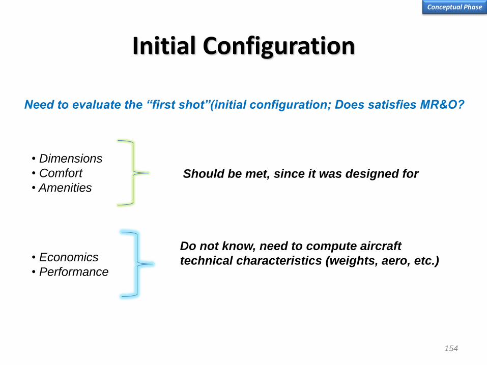
154
Initial Configuration
Conceptual Phase
Need to evaluate the “first shot”(initial configuration; Does satisfies MR&O?
• Dimensions
• Comfort
• Amenities Should be met, since it was designed for
• Economics
• Performance
Do not know, need to compute aircraft
technical characteristics (weights, aero, etc.)
155
Initial Configuration
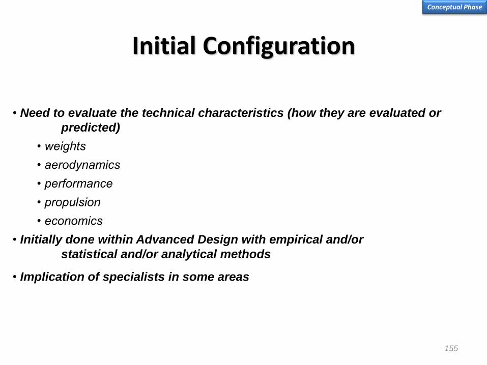
Conceptual Phase
• Need to evaluate the technical characteristics (how they are evaluated or
predicted)
• weights
• aerodynamics
• performance
• propulsion
• economics
• Initially done within Advanced Design with empirical and/or
statistical and/or analytical methods
• Implication of specialists in some areas

156
Pressure Distribution on Fuselages
Conceptual Phase
Mach number distribution on fuselage nose,
McDonnell-Douglas DC-10, Mach = 0.85.
Comparisons of crown line pressure distributions for a low
wing transport configuration at M∞ = 0.84 and α = 2.8o ,
Boeing 747. Source: AIAA Paper No 72-188

Forward Fuselage of Some Airliners
Conceptual Phase
EMB-110 Bandeirante
Boeing 777
McDonnell Douglas DC-10
Embraer E-170

Forward Fuselage of Some Airliners
Conceptual Phase
Airbus A-320
Boeing 767
Boeing 737
Embraer ERJ-145

159
Cabin Design
Conceptual Phase
Most aircrafts are designed from the “inside –out”
Geometric definitions dictated by cabin and cockpit comfort and
ergonomics as defined in the MR&O
Cabin Layout Definition
• Cross-section (seats abreast, personal comfort, ergonomics)
• Windows
• Doors and stairs
• Lavatories, galleys, wardrobes
• Emergency egress and emergency equipment
• Environmental climate control, air conditioning

Configuração Básica Aeronave
160
ERJ 145 CRJ 200 DHC 8 Dornier 328
ATR 42 / 72 Saab 340 / 2000
Definição da “Cross Section”
EMBRAER 170/190
Benchm
ark
Conceptual Phase

161
Cabin Design
Conceptual Phase

162
Cabin Design
Conceptual Phase

163
Cabin Design
Conceptual Phase
Volume above cabin floor
• Housing the passengers and seats (sometimes systems, e.g. avionics racks, PATS or
Branson tanks)
• Aisle(s)
• Overhead bins, galleys, and, lavatories and wardrobes (or freight)
Volume below the floor
• Cargo and freight
• Landing gear
• Center wingbox(or above)
• Fuel tank(s)
• Various systems
Key considerations when choosing the geometry
• Functionality (living volume) : maximize
• Weight (stress and loads) : minimize
• Drag (performance) : minimize
• Manufacturing (cost) : minimize

164
American Airliners Operating in the 30s
Conceptual Phase Technology Assessment
Prof. Bento Silva de Mattos

165
Early Jet Airliners
January 1962 January 1961 Convair 990 Coronado
Vickers VC-10
Douglas DC-8
Boeing 707
Aircraft
October 1958 July 1958
April 1964 June 1962
September 1959 May 1958
Service Entry First Flight
Conceptual Phase Technology Assessment
Prof. Bento Silva de Mattos

166
Early Jet Age
Late Jet Age
Boeing 707 / Douglas DC-8 / Boeing 747 / Sud-Aviation Caravelle
Bombardier CRJ-200/ Bombardier CRJ-700/Embraer ERJ-145 / Embraer E-Jets
Conceptual Phase Technology Assessment
Prof. Bento Silva de Mattos

167
Regional jets
September 1993
November 1992
December 1996
Service Entry
70 - 85 July 1994 Fokker 70
Avro RJ 70
Bombardier CRJ-100
Embraer ERJ-145
Aircraft
50 August 1995
70 - 82 July 1992
44 - 50 May 1991
Capacity (Pax) First Flight
No Props
October 1994
Conceptual Phase Technology Assessment
Prof. Bento Silva de Mattos

Some Airliners Operating in 2008
Early 80’s technology
Airbus A320
Boeing 767 Late 70’s technology
Boeing 737-200 Late 60’s technology
Conceptual Phase Technology Assessment
Prof. Bento Silva de Mattos

Technology Assessment
Conceptual Phase Technology Assessment
Concorde was an ogival (also "ogee") delta-winged aircraft with four Olympus engines based on those originally developed for the Avro
Vulcan strategic bomber. The engines were jointly built by Rolls-Royce and SNECMA. Concorde was the first civil airliner to have an (in
this case analogue) fly-by-wire flight control system. It also employed a distinctive droop snoot lowering nose section for visibility on
approach.
The principal designer who worked on the project was Pierre Satre, with Sir Archibald Russell as his deputy.
Concorde had an average cruise speed of Mach 2.02 (about 2,140 km/h or 1,330 mph) with a maximum cruise altitude of 18,300 meters
(60,000 feet), more than twice the speed of conventional aircraft. The average landing speed was 298 km/h (185 mph, 160 knots).
The flight deck
Concorde pioneered the following technologies:
For high speed and optimization of flight:
• Double-delta (ogee/ogival) shaped wings
• Variable inlet ramps controlled by digital computers
• Supercruise capability
• Thrust-by-wire engines, predecessor of today’s FADEC-controlled engines
• Droop-nose section for improved visibility in landing
For weight-saving and enhanced performance:
• Mach 2.04 (~2,200 kilometers per hour (1,400 mph) cruising speed for optimum fuel consumption (supersonic drag minimum, although turbojet engines
are more efficient at high speed))
• Mainly aluminum construction for low weight and conventional manufacture (higher speeds would have ruled out aluminum)
• Full-regime autopilot and autothrottle allowing "hands off" control of the aircraft from climb out to landing
• Fully electrically controlled analogue fly-by-wire flight controls systems
• Multifunction flight control surfaces
• High-pressure hydraulic system of 28 MPa (4,000 psi) for lighter hydraulic systems components
• Data Highways for the transmission of aerodynamic measurements (total pressure, static pressure, angle of attack, side-slip) from the Air Intake Sensor
Units at the front of the aircraft to the Air Intake Control Units mounted near the rear of the aircraft.
• Fully electrically controlled analogue brake-by-wire system
• Pitch trim by shifting fuel around the fuselage for centre-of-gravity control
• Parts made using "sculpture milling" from single alloy billet reducing the part-number count, while saving weight and adding strength
• Lack of Auxiliary power unit relying on the fact that Concorde will be used for services to big airports, where a ground air start cart would be available
Prof. Bento Silva de Mattos

Airbus Technology 1/2
A300
A300
A300FF
A310
Twin-engine, twin-aisle configuration
Triplex power and control systems
Advanced supercritical aerofoil
Full flight regime auto-throttle
Automatic wind-shear protection
Just in Time manufacturing
Cat. IIIA autoland
Digital auto-flight system
Two-person cockpit
Increased wing aspect ratio and thickness Advanced CRT cockpit displays with unique electronic centralised aircraft monitor
Composite materials (secondary structure)
Electrical signaling of secondary controls
1974
1977
1982
1983
A300-600 Half-generation advance” turbofan
powerplant (CF6-80C2)
1985
Conceptual Phase Technology Assessment
Prof. Bento Silva de Mattos

A310-300
A320
A330
A340
Advanced aluminium alloys Composite materials in primary structure Trim tank/centre-of-gravity control Carbon brakes, radial tyres
Sidestick controller Fly-by-wire Second generation digital auto flight system Extensive use of composites and advanced
aluminium alloys Active controls
Extension of A310/A300 and A320
advanced technology
All new advanced technology wing
CCQ & MFF
1985
1988
1993
A380 1999 Carbon Fiber Reinforced plastic (CFRP) for
primary structures
GLARE on upper fuselage panels
Laser welded lower fuselage
New Ethernet architecture for flight controls
Decentralized & high pressure hydraulics
system
Airbus Technology 2/2 Conceptual Phase
Technology Assessment Prof. Bento Silva de Mattos

172
R&T delivery to A380 Some examples of successful research
Centre wing box in CFRP
New four post main landing gear (4-6-6-4 wheels configuration)
Full double deck fuselage
Horizontal tail plane designed for relaxed stability
New front Fuselage concept Upper fuselage
skin in GLARE
Dual air conditioning pack concept
Variable frequency
power generation
2 hydraulic (5000 psi ) + 2 electrical channel architecture for flight controls and landing gear
Electro-hydraulic actuators
Integrated and modular avionics architecture (IMA)
On board maintenance system
Skin to Stringer Welding (first on A318)
Automated
wing assembly
Bonded metallic
outwing box
Flap vortex
generators
Extensive use
of Knowledge Based
Engineering
High Re (Reynolds
Number) Wing
Design
Carbon Composite Section 19
Technologies have to be developed generally and then
applied on products
Conceptual Phase Technology Assessment

173
Composite Solutions Applied
Throughout the 787
Carbon laminate
Carbon sandwich
Fiberglass
Aluminum
Aluminum/steel/titanium pylons
Composites
50%
Aluminum
20%
Titanium
15%
Fiberglass
10%
Other
5%
Conceptual Phase
Technology Assessment
Prof. Bento Silva de Mattos

Boeing 787: Quiet for Communities San Diego Intl Airport RWY 27
85 dBA NADP 2 (ICAO-B) Takeoff noise contours - 3000 nm mission
767-300
787-8
777-200
Conceptual Phase
Technology Assessment

Boeing 787: Quiet for Communities San Diego Intl Airport RWY 09
85 dBA NADP 2 (ICAO-B) Takeoff noise contours - 3000 nm mission
767-300 787-8 777-200
Conceptual Phase
Technology Assessment

Airframe Technology What is being done?
Ram Air Turbine
(aux elec)
AntennaElectrical/ Hydraulics
(Nose steering)
Ox bottles
Avionics
(inside Pressure cabin)
- Alt & Airspeed
- Navigational
- Multifunctional Disply (MFD)
- Primary Flight Display (PFD)
Avionics
(inside Pressure cabin)
- Flight Data Recorder
System runs
-ECS
-Electrical
-Hydraulics
Fuel pumps
Electrically driven Hydraulic pump
Electrical “J” Box
Batteries
Air pre-coolers
Hydraulic reservoirs
Hydraulic accumulators
Fuel heat exchanger
Air cycle machines
Fuel pumps
Hydraulic Pumps
Electrical generators
APU
Supersonic Business Jet
Conceptual Phase
Technology Assessment
Prof. Bento Silva de Mattos

More Ideas...
The objective here is to reduce the installed
power and systems on the aircraft as a
means to reduce weight and fuel
consumption. For take-off, electrical, steam
or magnetic devices using oil based,
nuclear or solar energy sources could be
used. Aircraft ramps, MAGLEV or catapults
could be used, using supplementary rocket
power. For landing aircraft weight could be
reduced by eliminating the undercarriage
with landings on water or on small cars
using electro-magnetic fields to position the
aircraft, para-foil landings etc.
Ground-based power sources for take-off and
landing
Conceptual Phase
Technology Assessment
Prof. Bento Silva de Mattos

More Ideas...
The concept envisages very large - possibly
nuclear-powered - aircraft flying on stable
circuitous routes that connect major centers of
population. These large cruisers remain airborne
for very long periods so that they could be
considered to be permanently cycling around
their designated route. They would fly at an
economical altitude and speed which would not
vary substantially. Linking these cruisers to fixed
bases near the population centers would be
short range shuttle aircraft designed only to
travel from the ground to the an interception with
the cruiser and back again. The feeder airliners
would be able to land on or dock with the cruiser
for the transfer of passengers and freight,
possibly via a kind of pallet system. New
methods of air refueling would need to be safer
and easer to handle than the current system and
automation would be required. The design of the
feeder aircraft would also need attention –
possibly an advanced super quiet VSTOL
aircraft with pre-loaded passenger containers.
The Cruiser/Feeder concept including mid-air refueling
Conceptual Phase
Technology Assessment

Need to Develop capabilities for multiple challenges
Past : one single
concept
to best meet all
requirements
Past : one single
concept
to best meet all
requirements
Past : one single concept
to best meet all requirements
The idea is to
identify the
concepts to explore
the more relevant
capabilities and
meet the widest
range of challenges
1 - The Low Cost A/C
2 - The Green A/C
3 - The Passenger Friendly
4 - The Value of Speed
5 - The Flying Truck
Today : concepts
tailored to fit specific
sets of requirements
Conceptual Phase Prof. Bento Silva de Mattos

180
CG Location
The precise location of
the aircraft cg is
essential in the
positioning of the landing
gear, as well as for other
applications, e.g., flight
mechanics, stability and
control, and
performance. Primarily,
the aircraft cg location is
needed to position the
landing gear such that
ground stability,
maneuverability, and
clearance requirements
are met.
Conceptual Phase
Prof. Bento Silva de Mattos

Preliminary Weight Estimation
• Aircraft weight, and its accurate prediction, is critical as it affects all aspects of performance.
• Designer must keep weight to a minimum as far as practically possible.
• Preliminary estimates possible for take-off weight, empty weight and fuel weight using basic requirement, specification (assumed mission profile) and initial configuration selection.
Conceptual Phase
Prof. Bento Silva de Mattos

Preliminary Weight Estimation Process – Flow Diagram
Conceptual Phase Prof. Bento Silva de Mattos

Preliminary Weight Estimation Class I Approach
• Most aircraft of reasonably conventional design can be assumed to fit into one of the 12 categories.
• New correlations may be made for new categories (e.g. UAVs).
• Account may also be made for effects of modern technology (e.g. new materials) – method presented in Roskam Vol.1, p.18.
• Raymer method uses Table 3.1 & Fig 3.1 (p.13).
Conceptual Phase
Prof. Bento Silva de Mattos
0 0
e
and C wetE D fe
r f
SW f W C
S

Class I Drag Estimation Conceptual Phase Prof. Bento Silva de Mattos
A good approximation to a clean configuration (high lift systems retracted) low speed drag
polar is that represented by the classical parabolic polar
Where CDO is the drag at zero lift, and CL
2 /πAe is the lift dependent drag. In the strict sense, the drag polars are not parabolic; in
practical sense, however, this representation is a reasonable one.
The zero-lift parasite drag with the high lift system retracted is estimated by empirical methods which rely heavily on wind tunnel
and flight test data gathered during previous transport development programs. The basic equivalent parasite drag for the
individual airplane components is defined as
Where Cf is the flat plate skin friction coefficient, including the effects of roughness, and K is a form factor which accounts for the
effects of thickness, supervelocities, and pressure drag. Swet/Sref is the ratio of wetted area to the reference area.
The flat plate skin friction coefficient can be obtained from various sources for fully turbulent flow and are based on the
characteristic length of each component. The characteristic length for a body (fuselage, nacelle) is the overall length and for
aerodynamic surfaces (wing, tail, and pylon) it is the exposed mean aerodynamic chord. Roughness effects are due to
excrescences such as protruding rivets, steps, gaps and bulges in the skin, etc, which result from typical manufacturing
procedures. This is accounted for by an equivalent roughness. This equivalent roughness has been determine by equating the
flight test zero lift parasite drag for the DC-8, DC-9 and DC-10 to a detailed estimate of the parasite drag and solving for
roughness. This value has been determined to be 0.00095 inch and is, within the accuracy of the flight data, a constant value.
The form factor for aerodynamic surfaces is a function of average thickness ratio and of the sweep of the surface, and may be
determined from a data base or appropriate two- or three-dimensional wind tunnel data. The form factor for aerodynamic bodies is
a function of overall body fineness ratio and may also be determined from a data base or appropriate wind tunnel data.
An additional miscellaneous excrescence drag is due to the protuberances such as light and antenna fairings, drain masts,
probes, unavoidable mismatches, holes, air-conditioning system, etc, which all aircraft are required to have.
Ae
CCC L
DD
2
0
ref
wetfcompD
S
SKCC 0
Source: AGARD LS-67, 1974, lecture 2

Roskam’s Weight Estimation Method
Category 7 Category 8
Conceptual Phase
Prof. Bento Silva de Mattos
0 EW f W

Weight Estimation Engine
Conceptual Phase
Dry engine weight. Source: NASA CR 2320
En
gin
e w
eig
ht
– 1
00
0 l
b
Net sea level static thrust – 1000 lb
Prof. Bento Silva de Mattos

Weight Breakdown Conceptual Phase Prof. Bento Silva de Mattos

Drag Estimation
Conceptual Phase
Drag
•Empirical
•semi-empirical
•CFD
•wind tunnel

189
Lift-to-Drag Ratio Estimation
max
0
1( / )
2 D
e ARL D
C
Source: Loftin, LK, Jr.. Quest for performance, The evolution of modern aircraft. NASA SP-468
Conceptual Phase Prof. Bento Silva de Mattos

190
Effective Lift-Curve Slope
Helmbolt equation:
Comparison of a NACA 65-210 airfoil lift curve with that of a wing
using the same airfoil (McCormick).
22)/()/( ARCC
ARCC
ll
lL
Conceptual Phase Prof. Bento Silva de Mattos

191
Low-speed Aerodynamics
Conceptual Phase Prof. Bento Silva de Mattos

Low-speed Aerodynamics Evaluation
Conceptual Phase
Source: Bombardier Aerospace
Prof. Bento Silva de Mattos

Estimation of CL,max
• Wing CL,max is always less than the section maximum value.
• An initial approximation of CL,max for a swept wing is:
cos)(9.0)( 2max,3max, DLDL CC
Conceptual Phase
Prof. Bento Silva de Mattos

194
Effect of High-Lift Devices
Effect of leading edge devices on lift curve (Jenkinson).
Conceptual Phase
Prof. Bento Silva de Mattos

195
Estimation of CL,max
Definition of flapped wing area (Roskam).
HLrefflapped2max,3max, cos)/()()( SSCC DLDL
Conceptual Phase
Prof. Bento Silva de Mattos

196
Refined Method for Computing CL,max
Spanwise lift distribution (Jenkinson).
Conceptual Phase
Prof. Bento Silva de Mattos

197
CFD Calculation
Conceptual Phase Prof. Bento Silva de Mattos

Performance
• Now that the characteristics of the aircraft are known
performances can be computed • Performances have direct impact on configuration
and vice-versa • Most important performance items:
– takeoff – ICA (Initial Cruise Altitude) – cruise – landing – operating costs
198
Conceptual Phase Prof. Bento Silva de Mattos
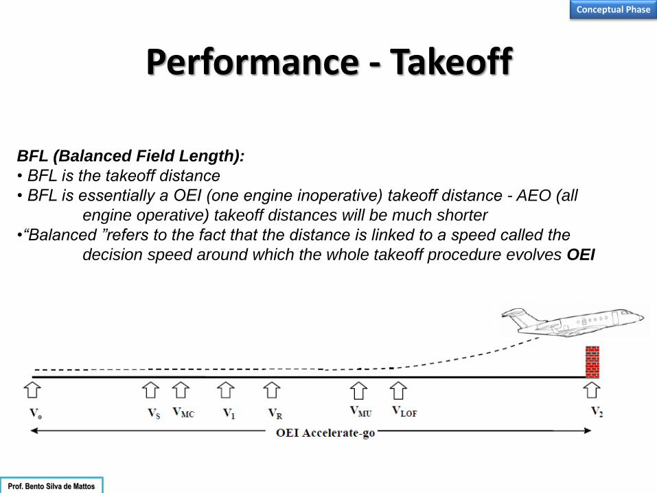
Performance - Takeoff
Conceptual Phase
Prof. Bento Silva de Mattos
BFL (Balanced Field Length):
• BFL is the takeoff distance
• BFL is essentially a OEI (one engine inoperative) takeoff distance - AEO (all
engine operative) takeoff distances will be much shorter
•“Balanced ”refers to the fact that the distance is linked to a speed called the
decision speed around which the whole takeoff procedure evolves OEI

Performance - Takeoff
Conceptual Phase
BFL (Balanced Field Length):
A good simple formula to approximate BFL is as follows
LtoC
WT
SWk
BFL
Prof. Bento Silva de Mattos

Performance - Climb
Conceptual Phase
• Important thrust sizing parameter
• Wing should be sized for achieving ~ best L/D at top of climb
• and Max. Climb Thrust sized at that point
Climb (ICA, Initial Cruise Altitude)
Prof. Bento Silva de Mattos

Performance - Range
Conceptual Phase
• Important parameter as it sizes the takeoff weight of the aircraft
• This is the classical Breguet Range Equation:
• Although not accurate for a whole mission, it gives a good understanding
of the driving parameters
Prof. Bento Silva de Mattos

Performance Evaluation
203
Prof. Bento Silva de Mattos Conceptual Phase

Performance Evaluation Prof. Bento Silva de Mattos Conceptual Phase

Performance – Rate of Climb
Conceptual Phase Prof. Bento Silva de Mattos

Performance – Rate of Climb
Conceptual Phase Prof. Bento Silva de Mattos

Performance – Time to Climb
Conceptual Phase Prof. Bento Silva de Mattos
Calculating R/C
dt
dhVCR sin/
CR
dhdt
/
Integrating
i
n
i
h
h
t
t CR
h
CR
dhdt
1 //
2
1
2
1
Calculating time to climb graphically
• Plot (R/C)-1 versus h
• Approximate the area under the curve
• Subtract time to climb from the starting altitude
bhaC
R max
abhabbha
dhdtt
ht
lnln1
2
00
min
2min

Performance – Climb Profile
Conceptual Phase Prof. Bento Silva de Mattos
The speed schedules for climb to the
cruise altitude are customarily shown as a
combination of calibrated airspeed at the
lower altitudes, changing to Mach number
at the higher altitudes. Calibrated airspeed
(or, on the older airplanes not equipped
with air data computers, indicated
airspeed) and Mach number are the
speeds available to pilots on the flight
deck, hence we always state the climb
speed schedules in those units.
An example would be a climb speed
schedule shown as 290/.78, meaning 290
knots CAS at the lower altitudes, then
Mach 0.78 at the higher altitudes. That’s
one of the published climb speed
schedules for the 757-200 airplane.
At altitudes below 30,875 feet (you’ll see why it’s that
value in just a minute) you see a sloping line of a
constant 290 knots CAS as it varies with altitude
following the equation:

Conceptual Phase
Payload vs. Range
An aircraft does not have a single number that represents its range. Even the
maximum range is subject to interpretation, since the maximum range is
generally not very useful as it is achieved with no payload. To represent the
available trade-off between payload and range, a range-payload diagram may
be constructed as shown in the figure below

Conceptual Phase Payload vs. Range Graphs Prof. Bento Silva de Mattos
Boeing 737-700 Boeing 737-200 Source: http://www.boeing.com

Conceptual Phase
Range Payload Profile Prof. Bento Silva de Mattos
Cessna Citation CJ4
Source: Business & Commercial Aviation, March 2010

Conceptual Phase
Specific Range Graphs Prof. Bento Silva de Mattos
Cessna Citation CJ4
Dassault Falcon 7X
Source: Business & Commercial Aviation, March 2010

Aircraft Systems - Engine
213
Engine : most important (and expensive) system on aircraft
• The primary goal is to determine the minimum thrust and fuel burn to satisfy aircraft performance
Other requirements include cost, noise/vibration, installation effects, weight, reliability and availability; involves analysis of 2-3 off-the-shelf power plants
May involve studying paper engines assuming a trade-off between BPR, OPR, mass flow, temperatures, etc.
May also involve the investigation of alternative technologies
• Sizing calculations conducted in order to determine the scale, i.e. dimensions and weight Critical conditions for the engine are takeoff, climb, cruise, OEI; one critical scenario is generally the
determining case • During conceptual design sizing and optimization analysis Engine performance usually calculated from mathematical model provided by the engine
manufacturer (“deck”) A deck may not always be available, in such cases use similar engine but linearly scaled to desired
engine size Alternatively, a first-order rubber engine model is utilized, i.e. fractional change from a reference
engine table
Conceptual Phase

Conceptual Phase
Turbofan thrust specific fuel consumption variations (High BPR)
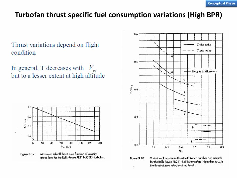
Conceptual Phase
Turbofan thrust specific fuel consumption variations (High BPR)

Turbofan Performance Variation
Turbofan thrust specific fuel consumption variations (High BPR)
216
Conceptual Phase

Turbofan Engine Characteristics Estimation
• Non-afterburning engines
Conceptual Phase
• Afterburning engines
0.0451.1
0.4 0.2
0.5 0.04
0.12
max
0.9 0.02
0.05
0.084
2.22
0.393
0.67
0.60
0.88
BPR
BPR
BPR
T
BPR
cruise
BPR
cruise
W T e
L T M
D T e
SFC e
T T e
SFC e
Source: Raymer, Aircraft Design
0.811.1 0.25
0.4 0.2
0.5 0.04
0.12
max
0.74 0.023
0.186
0.063
3.06
0.288
2.1
1.6
1.04
BPR
BPR
BPR
T
BPR
cruise
BPR
cruise
W T M e
L T M
D T e
SFC e
T T e
SFC e
W = weight T = takeoff thrust BPR = by-pass ratio (0<BPR<6) M = max. Mach number Cruise is at 36,000 ft and 0.90M
Where

Vertical Tail Design Considerations Critical Engine
Conceptual Phase
When one engine becomes inoperative, a torque will be developed which depends on the lateral distance from the center of
gravity (C.G.) to the thrust vector of the operating engine multiplied by the thrust of the operating engine. The torque effect
attempts to yaw the aircraft's nose towards the inoperative engine, a yaw tendency which must be counteracted by the pilot's use
of the flight controls. Due to P-factor, the right-hand engine typically develops its resultant thrust vector at a greater lateral
distance from the aircraft's C.G. than the left-hand engine. The failure of the left-hand engine will result in a larger yaw effect via
the operating right-hand engine, rather than vice-versa. Since the operating right-hand engine produces a stronger yaw moment,
the pilot will need to use larger control deflections in order to maintain aircraft control. Thus, the failure of the left-hand engine is
less desirable than failure of the right-hand engine, and the left-hand engine is critical.
It is important to note, however, that this example depends upon both propellers turning clockwise as viewed from the rear. On
aircraft with counterclockwise-turning engines (such as the de Havilland Dove), the right engine would be critical.
Aircraft which have counter-rotating propellers do not have a critical engine defined by above mechanism.
Aircraft with center-line thrust propeller configurations (e.g. the Cessna 337) may still have a critical engine, if failure of one engine
(either the front or rear) has more of a negative effect on aircraft control or climb performance than failure of the other engine.
Source: Wikipedia

Vertical Tail Design Considerations P-factor
Conceptual Phase
Causes - When an aircraft is in straight and level flight at cruise speed, the propeller disc will be normal (i. e. perpendicular) to
the airflow vector. As airspeed decreases and wing angle of attack increases, the engines will begin to point up and airflow will
meet the propeller disc at an increasing angle, such that horizontal propeller blades moving down will have a greater angle of
attack and relative wind velocity and therefore increased thrust, while horizontal blades moving up will have a reduced angle of
attack and relative wind velocity and therefore decreased thrust. (Vertical blades are not affected). This asymmetry in thrust
displaces the center of thrust of the propeller disc towards the blade with increased thrust, as if the engine had moved in or out
along the wing. The engine with the down-moving blades towards the wingtip produces more yaw and roll than the other engine,
because the moment (arm) of that engine's thrust about the aircraft center of gravity is greater. Thus, the engine with down-
moving blades towards the fuselage will be "critical", because its failure will require a larger rudder deflection by the pilot to
maintain straight flight than if the other engine had failed.
Effects on single engine propeller aircraft
(As viewed by the pilot), the aircraft has a tendency to yaw to the left if using a clockwise turning propeller (right hand), and to
the right with a counter-clockwise turning propeller (left hand). The right-hand propeller is by far the most common. The effect
is noticeable during take off[ and in straight and level flight with high power and high angle of attack.
Effects on multi engine propeller aircraft (clockwise rotation)
With engines rotating in the same direction the p-factor will affect VMC (minimum control speed) in asymmetric flight.
Considering right-hand tractor engines (lines projecting from propeller discs represent the p-factor induced thrust lines):
Source: Wikipedia
At low speed flight with the left engine failed, the off-centre thrust produced by the right engine creates a larger yaw-couple to left than the opposite case. The left engine in this scenario is the critical engine, namely the engine whose failure brings about the more adverse result. In the case of using counter-rotating engines (i.e. not rotating in the same direction) the p-factor is not considered in determining the critical engine.

Aircraft Systems – Fuel System (F-18) Conceptual Phase
An artist’s cut-away drawing shows the location of the internal fuel tanks in the FA-18E. Most of
the interior of the center fuselage and the inboard wing sections are taken up by fuel tanks. Also
note that are fuel tanks inside the vertical tails just ahead the rudders.
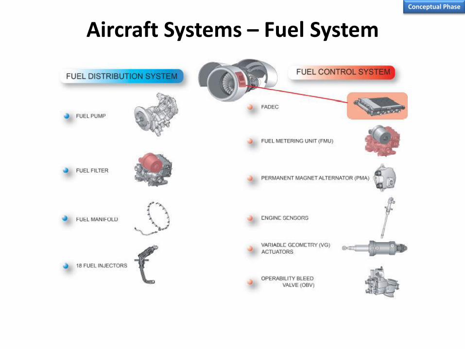
Aircraft Systems – Fuel System Conceptual Phase

Aircraft Systems – Fuel System (F-16C) Conceptual Phase
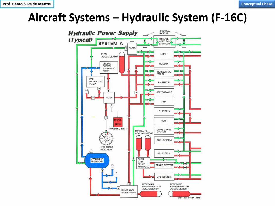
Aircraft Systems – Hydraulic System (F-16C)
Conceptual Phase Prof. Bento Silva de Mattos

Structural Layout
• Distribuição cavernas e reforçadores.
• Segmentação para produção, parceiros e logística.
• Requisitos de certificação.
•Para instalar os sistemas temos que apóia-los, fixá-los em algum lugar, assim é comum a estrutura ser o ponto de partida.
•Trata-se da parte de maior longevidade do Projeto.
Conceptual Phase

Arquitetura Estrutural
•Distribuição longarinas na Asa.
•Fixação Trem de Pouso.
•Fixação/Distribuição superfícies de controle.
•Sistema degelo.
•Fixação Pilone.
• Janelas de Inspeção.
•Fixação Asa/Stub.
•Combustível.
• Instal. Superf. hipersustent.
Wing
Conceptual Phase

Access Doors
Conceptual Phase
F-16
F-15

Integração Preliminar
Reserva de Espaços e Soluções
Conceptual Phase

Logística/Segmentação Industrial
229
Este tipo de questão, dependendo dos parceiros e da dimensão do avião, pode ter um forte impacto nesta fase do projeto da Estrutura.
Às vezes tem-se uniões adicionais em função da logística (containeres, carretas, estradas, redes elétricas, viadutos, etc).
Conceptual Phase

Cost Structure
230
Non-recurring Recurring
Infra-structure
Engineering
Prototypes
Flight tests
Certification
Manufacturing
System integration
Materials
Processes
Overhead & Management
Taxes, fees
Conceptual Phase

Recurring Cost
Non-recurring Cost
Cost Diagram
231
Prof. Bento Silva de Mattos Conceptual Phase

Cost Estimation
232
Conceptual Phase
Airplane

Learning Curve
233
2log
log
1
iR
n NTT • R1 = 0.93 (until 10th aircraft)
• R2 = 0.96 (after 10th aircraft)
• T598 = 56119mh (estimated)
• T10 = 71407mh (equation)
• T1 = 90874mh (equation)
0 100 200 300 400 500 600 5
6
7
8
9
10 x104
To
tal m
an
-ho
ur
req
uir
ed
Aircraft number
Maior quantidade aviões => menor custo => mais lucros.
Conceitos Gerais: Composição de Custos
Conceptual Phase
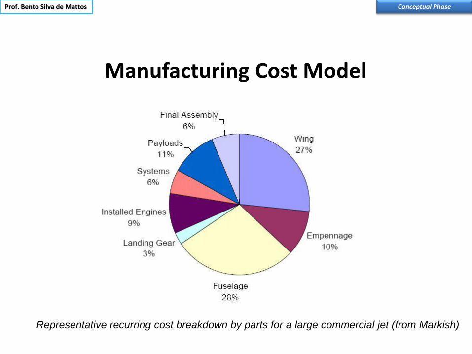
Manufacturing Cost Model
Representative recurring cost breakdown by parts for a large commercial jet (from Markish)
Prof. Bento Silva de Mattos Conceptual Phase

Lifecycle Cost
235
Conceptual Phase
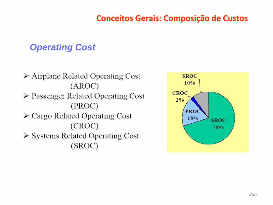
Conceitos Gerais: Composição de Custos
236
Operating Cost

Conceitos Gerais: Composição de Custos
237
AROC

NECESSIDADES DO COMPRADOR DO PRODUTO
238
CUSTO OPERACIONAL DA AERONAVE
QUAL É O NEGÓCIO DAS EMPRESAS AÉREAS COMERCIAIS ?
PRODUZIR E VENDER ASSENTOS-MILHAS - ASM - ( OU ASSENTOS-QUILÔMETROS )
CADA ASM TEM UM DETERMINADO CUSTO PARA O OPERADOR, COMO SEGUE :
TOC = DOC + IOC
TOC = CUSTO OPERACIONAL TOTAL
DOC = CUSTO OPERACIONAL DIRETO
IOC = CUSTO OPERACIONAL INDIRETO
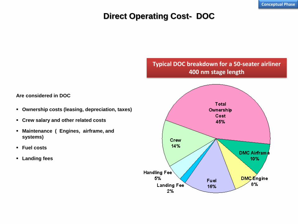
Direct Operating Cost- DOC
Are considered in DOC
Ownership costs (leasing, depreciation, taxes)
Crew salary and other related costs
Maintenance ( Engines, airframe, and
systems)
Fuel costs
Landing fees
Typical DOC breakdown for a 50-seater airliner 400 nm stage length
Conceptual Phase
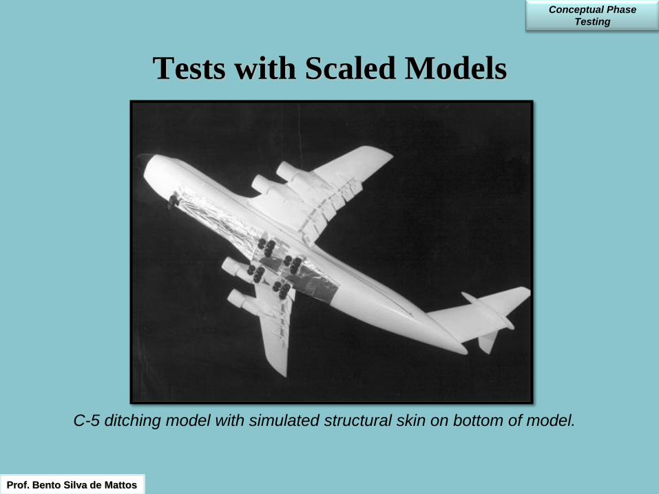
Tests with Scaled Models
C-5 ditching model with simulated structural skin on bottom of model.
Prof. Bento Silva de Mattos
Conceptual Phase
Testing

Tests with Scaled Models
Conceptual Phase
Testing
Active load alleviation test of the C-5 in the Langley 16-Foot Transonic Dynamics Tunnel.
Prof. Bento Silva de Mattos
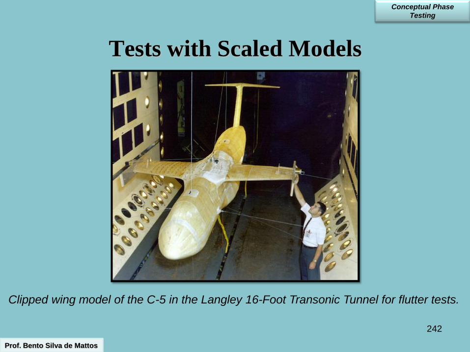
242
Tests with Scaled Models
Clipped wing model of the C-5 in the Langley 16-Foot Transonic Tunnel for flutter tests.
Prof. Bento Silva de Mattos
Conceptual Phase
Testing

243
Tests with Scaled Models
F-14 model in spin recovery tests in the Langley Spin Tunnel.
Prof. Bento Silva de Mattos
Conceptual Phase
Testing

244
Catapult facility experiments
A380 free-flight model in catapult facility,
ONERA Lille, and F1 wind tunnel, ONERA
Catapult
Recovery system
Gust
generators
• Characterization of Near and
Mid field (up to x/b=60)
• Test of 3 different A380
configurations
• Applied methods:
PIV / smoke visualization
2D and 3D simulations
5 hole probe (near field at
FI wind tunnel)
Prof. Bento Silva de Mattos Conceptual Phase
Testing
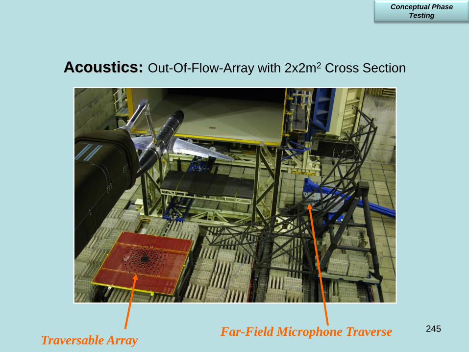
245
Acoustics: Out-Of-Flow-Array with 2x2m2 Cross Section
Far-Field Microphone Traverse Traversable Array
Conceptual Phase
Testing

Acoustics: Out-Of-Flow-Array with 4x4m2 Cross Section
Set-ups with Full-scale Models
Full-scale wing Full-scale landing gear
Conceptual Phase

247
Ground Effect Testing
Conceptual Phase
Prof. Bento Silva de Mattos

Flight Test with Scaled Model
Conceptual Phase
Prof. Bento Silva de Mattos
Langley technician Ronald White with one of two F-15 drop models
used for research on spin-entry characteristics.
Source: http://oea.larc.nasa.gov/PAIS/Partners/F_15.html

Early Wind-Tunnel Testing
249
At left
Túnel: NLR
Modelo: CMT1 (1/21)
Suporte da Balança Tras.
Total de Corridas: 105
Período: Abril/2001
A despeito dos grandes avanços das análises com CFD, os ensaios aerodinâmicos ainda são indispensáveis.
Conceptual Phase
Prof. Bento Silva de Mattos

Case Study : EMBRAER 170
250
CADA CASO É UM CASO.
A MELHOR CONFIGURAÇÃO PARA JATOS REGIONAIS DE PEQUENO PORTE ( FUSELAGEM
PARA TRÊS FILAS DE ASSENTOS ), POR UMA SÉRIE DE MOTIVOS, É A CONFIGURAÇÃO
ADOTADA PARA O ERJ 145 ( MOTORES NA FUSELAGEM ).
O CASO DO EMBRAER 170 É DIFERENTE; VÁRIAS CONFIGURAÇÕES FORAM FORMULADAS,
ANALISADAS E SUBMETIDAS À APRECIAÇÃO DOS CLIENTES POTENCIAIS, COMO SEGUE :
Conceptual Phase

251
Final choice for EMB 170 configuration: 4-abreast seating arrangement; double-bulbe fuselage cross section; underwing engines.
• Higher efficiency: shorter turnaround time (rear doors, easier engine inspection by crew
when airplane is on ground)
• Higher passenger comfort
• Stretched aircraft with lower balancing problems
• Lower MTOW
Case Study : EMBRAER 170
Conceptual Phase

252
Case Study : EMBRAER 170
A ) DERIVAÇÃO DO ERJ 145, ALARGANDO-SE AS PARTES CILÍNDRICAS DA FUSELAGEM :
Conceptual Phase

253
B ) FUSELAGEM ‘4-ABREAST’ CIRCULAR, MOTORES NA FUSELAGEM, ASA DERIVADA DO ERJ 145 :
Case Study : EMBRAER 170
Conceptual Phase
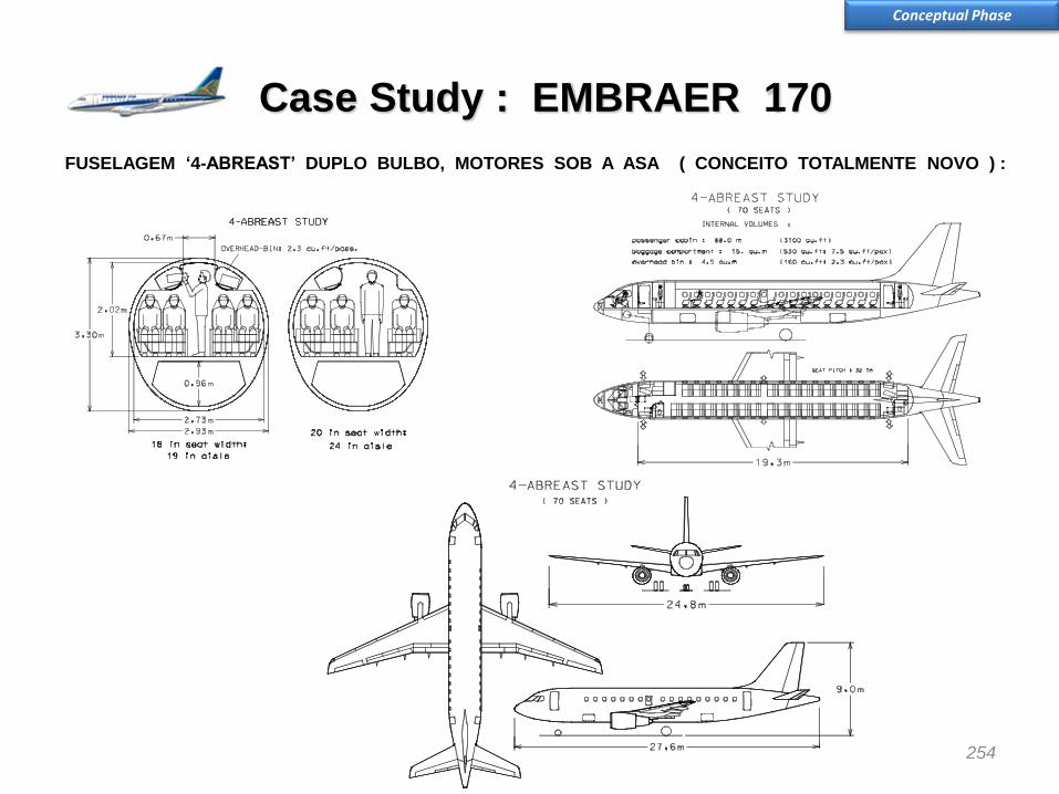
254
FUSELAGEM ‘4-ABREAST’ DUPLO BULBO, MOTORES SOB A ASA ( CONCEITO TOTALMENTE NOVO ) :
Case Study : EMBRAER 170
Conceptual Phase

255
D ) FUSELAGEM ‘5-ABREAST’ CIRCULAR, MOTORES SOB A ASA :
Case Study : EMBRAER 170
Conceptual Phase

256
• Quatro portas na cabine
• Menor tempo de serviço
no solo
• Posicionamento adequado
de pontos de serviço
• Compartimentos de
bagagem dianteiro e
traseiro
• Baixo risco de colisão de
equipamentos de apoio
• Fluxo simultâneo de
passageiros e serviço de
cabine
EMBRAER 170 : CONFIGURAÇÃO ESCOLHIDA
Case Study : EMBRAER 170
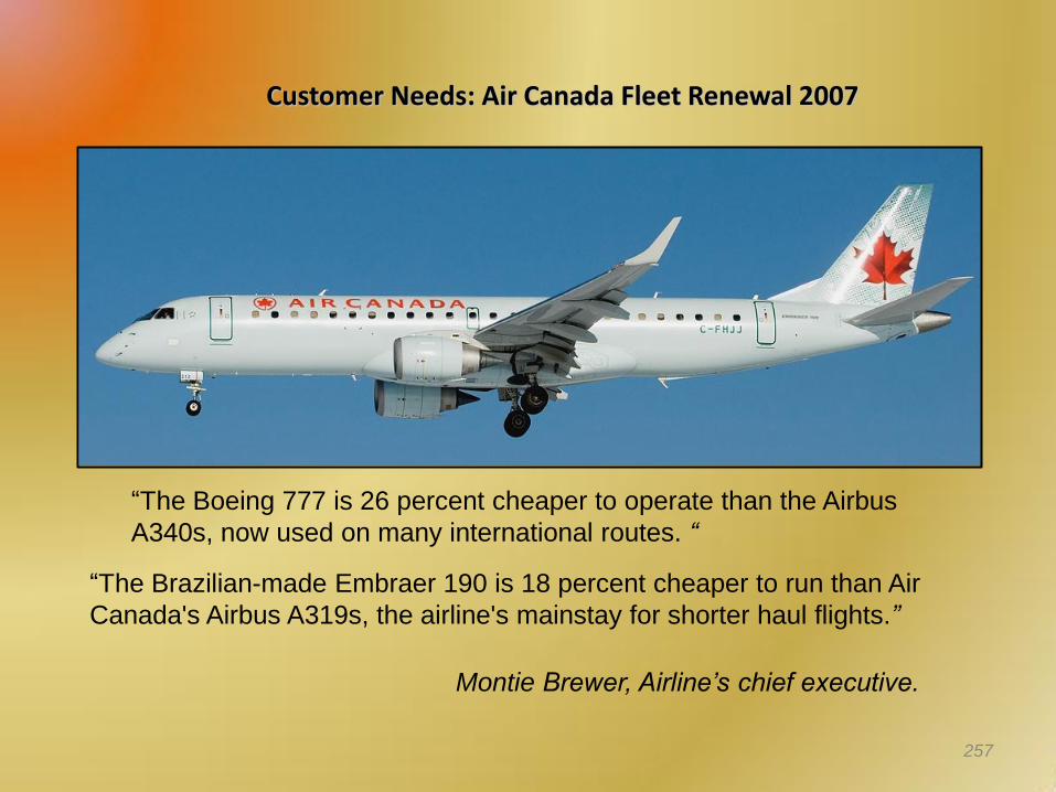
Customer Needs: Air Canada Fleet Renewal 2007
257
“The Boeing 777 is 26 percent cheaper to operate than the Airbus
A340s, now used on many international routes. “
“The Brazilian-made Embraer 190 is 18 percent cheaper to run than Air
Canada's Airbus A319s, the airline's mainstay for shorter haul flights.”
Montie Brewer, Airline’s chief executive.

• Aqui é tomada a primeira importante decisão de congelamento da configuração da aeronave
Basic Configuration Frozen
• Nesta etapa é definida a concepção estrutural e o sistema propulsivo, e não se muda mais. Pode até mudar, mas o preço é extremamente alto.
• Os demais itens, por exemplo, os aviônicos embarcados no Cockpit vêm num grau de prioridade menor, junto com outros elementos críticos.
Conceptual Phase
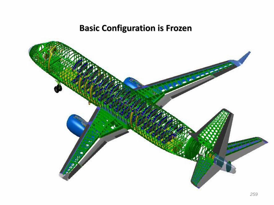
Basic Configuration is Frozen
259

Preliminary Design Phase

Arquitetura e definição funcional dos sistemas a serem aplicados no avião- diagramas funcionais, esquemas, layouts, DMU, etc..
Desenvolvimento dos estudos de engenharia e projeto. Projeto aerodinâmico final da fuselagem; da asa;das empenagens; dos hipersustentadores; ailerons do leme; e do profundor. Ensaios em túnel vento 2a etapa (cargas, deflexão flaps, influência do motor, avaliar efeitos).
Projeto estrutural preliminar dos segmentos da fuselagem, asa e empenagens horizontal/vertical.
Definição das cargas - estáticas e dinâmicas.
Avaliação da estabilidade e controle.
Consolidação do desempenho (QV).
Análise estrutural.
Definição detalhada das interfaces funcionais e físicas.
Elaboração das especificações técnicas dos subsistemas e componentes para compra.
Preparação de desenhos (3D) e layouts necessários à definição.
Escopo Fase 2-Projeto Preliminar
Analise de Riscos detalhada – FMEAs (Failure Mode and Effect Analysis).

• Identificação dos itens típicos/críticos e solução de todas as questões que possam impactar o projeto.
• Celebração de contratos com terceiros.
• Pesquisa de normas, padrões e leis aplicáveis.
• Definição do suporte à operação do avião.
• Plano de Produção e projeto preliminar do ferramental.
• Seleção final de fornecedores.
Scope of the Preliminary Design (Phase 2)
• Realização de ensaios de componentes e partes de soluções estruturais.

Integração de Sistemas: Mock-up de Madeira
Reserva de Espaços e Soluções
EMB-145

Desenvolvimento dos Estudos de Engenharia e Projeto
264
V P M
CATIA DMU Nav
•A vantagem do uso do CATIA é a migração (aproveitamento) de dados da Concepção, desde dos primeiros estudos na Fase 0.
•Nesta fase temos a maior influência desse aplicativo na eficiência do projeto.

Desenvolvimento dos Estudos de Engenharia e Projeto (2)
265
•A Gestão da Configuração é um item extremamente crítico entre os parceiros, principalmente quando se trata de um desenvolvimento globalizado.
•Caso 170
Gestão da Configuração

Desenvolvimento dos Estudos de Engenharia e Projeto (3)
266
Parceiro 1
Parceiro 2
Parceiro 3
Parceiro N
• Durante esta Fase é importante que os parceiros estejam o mais próximo possível. • Foi o que a Embraer fez com o 170. Parceiros na Empresa com acesso simultâneo.
Desenvolvimento Centralizado
VPM
Integradora

Arquitetura e Integração Detalhada
267
• A evolução dos DMU- Intensa nesta fase.
• Não é exagero afirmar que, hoje, só é possível esse tipo de parceria em função da existência desses aplicativos e redes.
DMUs

Projeto Ferramental/Instalações
270
Montagem final - Doca ou Linha ?

Projeto Ferramental/Instalações (2)
271
• Conhecimento Tecnológico
• Conhecimento das ferramentas.
• Alto envolvimento das áreas nas decisões de projeto.
• O envolvimento da Produção – processos- também vai sendo direcionado aos detalhes do projeto.
• Conhecimento do mercado de materiais.
Processos e Infra-estrutura

Access to Repair Work/ Maintenance Plan

Ensaios Qualificação/Certificação
273
• Ensaios em Solo de Sistemas e componentes
• Ensaios em Vôo-Fase 3
Estruturais estáticos-fases 2/3
Funcionais-fases 2/3
Ambientais-fases 2/3
• Ensaios são uma questão de compromisso, entre tempo e configuração. Quanto mais cedo melhor, mas não adianta estar muito fora da configuração final.
Tipos de Ensaios x Fase

Engineering Solutions
A 32nd Tactical Fighter Squadron F-15C climbs out shortly after takeoff . The bird-strike resistant windshield
consists of a center polycarbonate layer surrounded by a inner and outer layers of fusion bounded cast
acrylic. The polycarbonate canopy is made in two sections, separated by a thin red frame. The canopy
material is 0.74 cm thick and is covered by a abrasion resistant finishing. The F-15 engine intakes are fully
lowered to maximize airflow into the engines during takeoff.

275
Engineering Solutions
A mass balance tops
the vertical stabilizer of
the F-15 fighter. This
reduces flutter caused
by aerodynamic
forces. A Loral
AN/ALR-56 Radar
Warning Receiver
(RWR) is immediately
below the mass
balance. A red anti-
collision light is placed
below the RWR.
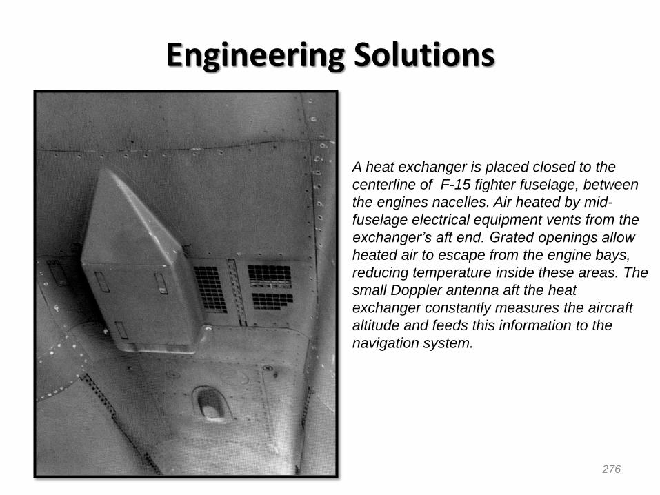
276
Engineering Solutions
A heat exchanger is placed closed to the
centerline of F-15 fighter fuselage, between
the engines nacelles. Air heated by mid-
fuselage electrical equipment vents from the
exchanger’s aft end. Grated openings allow
heated air to escape from the engine bays,
reducing temperature inside these areas. The
small Doppler antenna aft the heat
exchanger constantly measures the aircraft
altitude and feeds this information to the
navigation system.

277
Engineering Solutions
Boarding steps in use on a A-7D Corsair.
Note that the gun gas vent door is open.

Engineering solutions: Ultra Long-range Business Jet
Bombardier Global Express XRS
Bombardier developed a slat out/flaps up high-lift configuration that is intended to give operators more flexibility when operating at hot and high airports. The goal was to boost maximum allowable takeoff weight as limited by one engine inoperative, second segment climb requirements.
The alternate high-lift configuration produces mixed results. Less lift accompanied reduced drag with the slats out/flaps up configuration, resulting in higher V speeds and longer takeoff field lengths. In the case of the XRS, brake energy limits are also a factor, at times resulting in a substantial reducing in maximum allowable takeoff weight.
For instance, when departing from a 5000-foot elevation, ISA+20oC airport and assuming a slats out/flaps six-degree configuration, the XRS has a maximum allowable takeoff weight of 94,543 pounds and a 7,851-foot takeoff field length. The second segment climb requirements is a limiting factor.
Configuring with a slats out/flaps up at the same airport as above, takeoff weight is limited to 88,311 pounds because of the brake energy limits (1000 nm range penalty). Takeoff field length also increases to 8,359 ft because of higher V speeds.
Source: Business & Commercial Aviation, March 2010

Interfaces e Integração de Sistemas
• Questões de projeto e integração rigorosamente resolvidas
• Descrição Técnica e EBD editados.
• DMU e desenhos 3D elaborados.
• Análises elaboradas.
The aircraft is fully defined!

Arquitetura e Integração Detalhada (4)
A asa é um bom exemplo de um sistema de integração complexa: leve, resistente, importância primária no desempenho, volumosa, selada e com uma variedade enorme de sistemas fixados nela.

Detailed Design Phase

• Execução dos desenhos de fabricação em 2D e montagem, com o detalhamento completo da estrutura e sistemas:materiais e tecnologias; tolerâncias de fabricação; tratamento térmico/superficial; montabilidade; normas aplicáveis; etc.
• Fabricação do ferramental de produção.
• Elaboração dos processos de fabricação e montagem do avião.
• Elaboração do plano de manutenção e projeto do GSE.
Escopo da Fase 3 - Projeto Detalhado
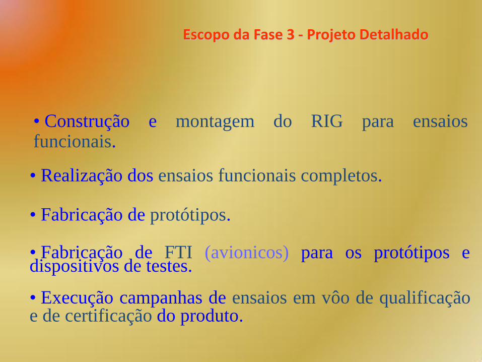
• Fabricação de protótipos.
• Fabricação de FTI (avionicos) para os protótipos e dispositivos de testes.
• Execução campanhas de ensaios em vôo de qualificação e de certificação do produto.
Escopo da Fase 3 - Projeto Detalhado
• Construção e montagem do RIG para ensaios funcionais.
• Realização dos ensaios funcionais completos.

Projeto Detalhado
EMBRAER
Partner 1
Partner 3
Partner N
Partner 2
Volta às origens. Parceiros com DMU parcial. Controle Geral da Embraer.
CC complexo.
•Continuação Caso Embraer 170

Projeto Detalhado (2)
285
• Depois que está tudo definido, gera-se os desenhos de fabricação em 2D.
•Embraer 170 ~ 60.000 Desenhos •Embraer 145 ~ 30.000 Desenhos
Desenhos 2D

Projeto Detalhado
286
• Grande esforço e alto custo na conversão.
• Em princípio, cada parceiro faz a sua parte.
Desenhos 2D

Construção dos Protótipos
287
•Automação x Manual

Construção dos Protótipos (4)
288
área do gabarito reservada
para aviões de maior
comprimento de fuselagem
(ERJ 190)
área do gabarito reservada
para aviões de maior
comprimento de fuselagem
Manufatura- Integração

Execução dos Ensaios
289
•Tipos de Ensaio: Solo e em Vôo
Estruturais
Ambientais (ruído e vibração)
Funcionais
Vôo (Desempenho/QDV)

Ensaios Funcionais
290
Iron Bird - Cockpit
Iron Bird - Instrumentation
Landing gear, wheels
and brakes
Hydraulic system

Ensaios Estruturais de Fadiga e Vibração
291
Limit and Ultimate Load Tests Completed
Residual Strenght Test

Ensaios Esrtuturais de Fadiga e Vibração (2)
292
Wing Up Bending Test

Bird Strike Testing
293
Windshield / Direct View Window
Flape

Other Testing
294
Estouro de Pneu

Outros Ensaios: Aeroacústica
Full-scale wing Full-scale landing gear

Flight Tests
296
• Ensaios configurados à certificação
• Tremendo investimento em protótipos e operações
• Programa de Ensaios-Plano e Instrumentação
• Esforço na elaboração dos relatórios de certificação
Performance – Flight Characteristics– Regular Operation as Airliner

Outros Ensaios
297
Baixas Temperaturas no solo
Alaska
Picture freely distributed in the Embraer’s Website

Flight Test Ice Contamination
Picture freely distributed in the Embraer’s Website

Flight Test - Flutter One of the most dangerous events that can occur in flight is a phenomena called "flutter". Flutter is an aerodynamically
induced vibration of a wing, tail, or control surface that can result in total structural failure in a matter of seconds. The
prediction of flutter is not a precise science and requires flight verification that flutter will not occur within the normal flight
envelope.
The aerodynamic surfaces of an airplane are constructed so that they can carry the loads that are produced in flight. For
example the wing must be capable of supporting the weight of the airplane as well as the additional lift produced during
turning flight. The resulting wing structure can be viewed as a blade or spring extending from the fuselage. If we "tap" the
spring with a hammer, it will vibrate at a frequency which relates to the stiffness of the spring. A stiff spring will vibrate at a
higher frequency than a more limber spring. This frequency is known as the "natural frequency" of the spring.
Flutter will usually occur at or near the natural frequency of the structure, that is, some small aerodynamic force will cause the
structure to vibrate at its natural frequency. If this small force persists at the same frequency as the natural frequency of the
structure, a condition called "resonance" occurs. Under a resonant condition, the amplitude of the vibration will increase
dramatically in a very short time and can cause catastrophic failure in the structure.

Flight Test - Flutter
Measures of Success
A successful flutter excitation test will meet the following test criteria:
• All instrumented parameters were recorded properly (see Table below).
• Airspeed and Mach number were stabilized at the desired condition.
• The structural mode of the surface was disturbed enough to identify frequency and damping.
• Damping of the structural mode was positive and not significantly different from previous tests at
lower airspeeds.
Parameter Used For
Elevator Position Excitation devices, or review for possible flight control interaction with the structure
Aileron Position
Rudder Position

Issuing Manuals
Source: Airbus Engine Exhaust Temperatures
Max Take-Off Power - GP 7200 Engines

Issuing Manuals
Source: Airbus Danger Areas of the Engines
Breakaway Power - GP 7200 Engines

Certification
303

Certification
304
Entrada em Serviço Dados obtidos em apresentações disponíveis na Internet
305

Embraer 170/175 – Frota em Operação
EI 19/JJan/06
Airline EIS A/C in Service Acc. FH
Lot Polish March 17, 2004 10 37,353
US Airways April 04, 2004 12 54,182
Alitalia April 26, 2004 6 19,263
Republic Holdings October 22, 2004 54 127,226
Cirrus Airlines January 15, 2005 1 1,824
AIR CANADA July 27, 2005 15 12,455
Hong Kong Express September 08, 2005 3 2,916
FINNAIR October 01, 2005 5 3,189
Paramount October 19, 2005 1 2,089
E 170/175 March 17, 2004 111 261,402
February 01, 2006 4 Saudi Arabian Airlines
Source: Airlines (as of Mar 17th 2006)
905

Operators 10
Aircraft in Service 111
Flight Hours 261,402
Flight Cycles 175,886as of Mar 17th 2006
E170/175
307
Embraer 170/175 - Estatística

Embraer 170/175 Dispatch Reliability
Aircraft in ServiceSchedule Reliability
(SR*)
Completion Rate
(CR*)
98.2% 99.6%
LOT
111
22
10
99.5%98.8%
98.2% 99.3%
308
(*) Monthly. Ref. date: Mar 15th, 2006
Europe
Worldwide

Reliability Diagnosis
309
Specific Operators
Environment
Product Technical
Issues
Spare Parts
Availability

E170/175 Dispatch Reliability Status
EMBRAER 170 - WW FLEET
Dispatch Reliability - 12 Months Running Average
99.6
97.8
96.0
96.5
97.0
97.5
98.0
98.5
99.0
99.5
100.0
FEB MAR APR MAY JUN JUL AUG SEP OCT NOV DEC JAN FEB MAR
SR
/CR
(%
)
CR - 12M SR - 12M
310
2005 2006
(as of Mar 15th, 2006)

E170/175 Dispatch Reliability Status
EMBRAER 170 - European FLEET
Dispatch Reliability - 12 Months Running Average
99.7
98.6
96.0
96.5
97.0
97.5
98.0
98.5
99.0
99.5
100.0
FEB MAR APR MAY JUN JUL AUG SEP OCT NOV DEC JAN FEB MAR
SR
/CR
(%
)
CR - 12M SR - 12M (as of Mar 15th, 2006)
2005 2006

Thank you folks!


