32
- 1 - Jeremy Kuzub Carleton University Systems and Computer Engineering Aircraft Design Using Procedural Generation for Gaming Applications
- 1 -
Jeremy Kuzub
Carleton University
Systems and Computer Engineering
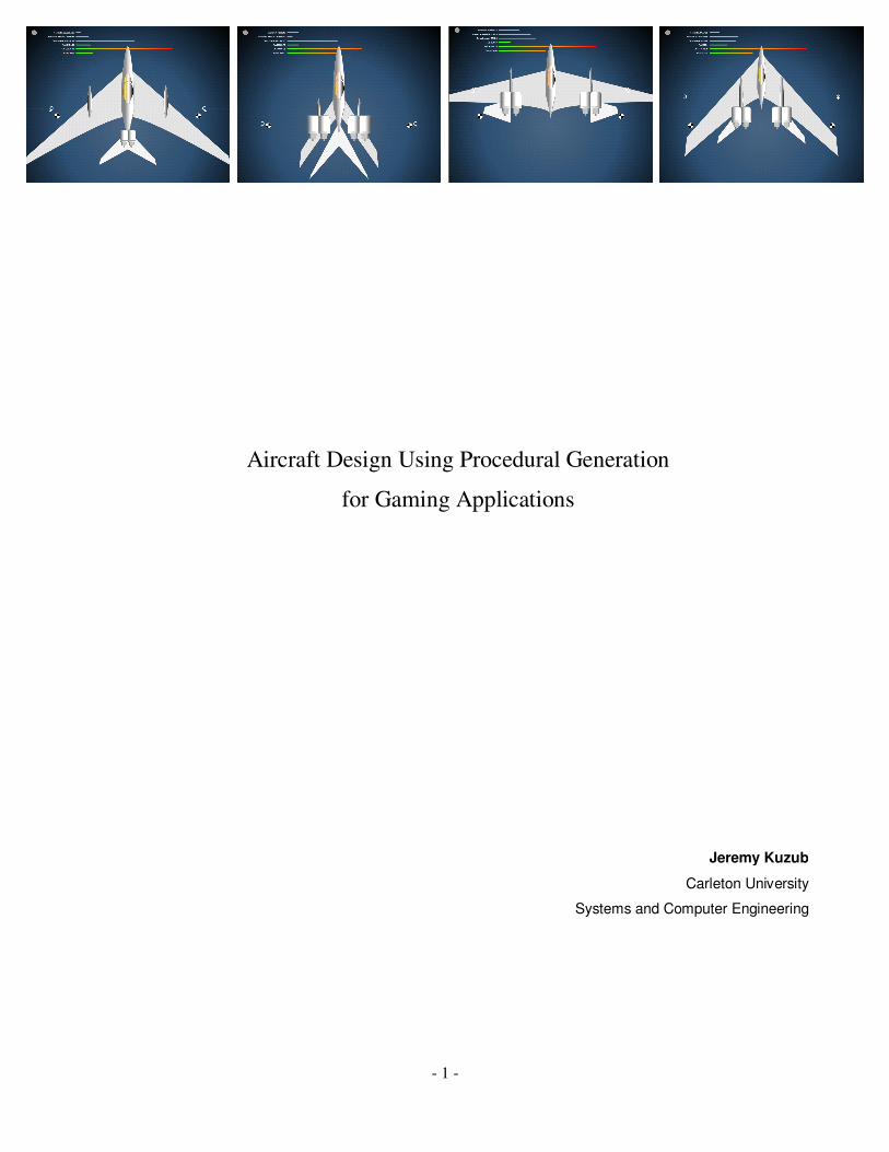
Aircraft Design Using Procedural Generation
for Gaming Applications

- 2 -
Abstract
A procedural generation algorithm for aircraft configurations is developed and
explored. Aircraft have common base in layout, modular components and
aerodynamic constraints, providing a rule-set and boundary conditions for
procedural generation development. Airframes are laid-out in 2D using a
module-by-module sequence. Pseudo-random number generation is used to
select dimensions and positioning, and bounded by several rule sets. Hypothetical
performance of the airframe is then calculated so that the result could be mapped
to other game components such as flight simulator dynamics and pilot A.I.
algorithms. Discussion of other applications in education and the design process
are also examined.
Web-based version of ACGen at:
www.jufaintermedia.com/acgen/
Source Code (Flash CS3) zip file with Windows .exe version of ACGen at:
www.jufaintermedia.com/acgen/source.zip
- 3 -
Part I: Background...................................................................................... 4
Part II: Implementation of ACGen .............................................................. 9
Part III: Further Development ................................................................... 14
Sources and References ............................................................................ 21
APPENDIX A: Code Listing .................................................................... 24
- 4 -
Part I: Background
Defining Procedural Generation
Procedural generation can potentially have a broad definition: generating objects
and behaviors from a set of rules rather than explicit control. In this context,
procedural generation could be said to apply to: particle effects, plant growth,
terrain and map generation, image rendering engines, music and soundtrack
synthesis, character behavior and AI, and even physics simulations
This definition could be narrowed down in a gaming application as: “content and
behavior not explicitly coded by the Developer.” In Practice: “is the Developer as
[pleasantly] surprised as the Player by the new game content?” This content
could include new environments, new characters, and new behaviors, in
unexpected (small) packages.
Procedural Generation as Data Compression
Using the same pseudo random seed to generate ‘weather’ will always generate
the same weather sequence. The longer the pseudo random sequence, the more
possible worlds come out of the procedural generation algorithm. The
compression aspect of procedural generation is used in applications such as
texture maps for games which are not explicitly stored but created through a
series of sequential operators, each acting on the previous operator’s output. The
generator code base is included with the deployed game or application and used
to ‘uncompress’ the series of procedural steps to produce the texture.
Procedural Generation as Simulation
Most procedural generation algorithms are attempting to duplicate either ntural
phenomena (terrain, plant growth) or design and engineering (cities, buildings).
The goal is to create believable output. To do this using a rule-set, the rules
themselves must be similar to laws that shape that aspect of reality. For example,
these could include models of physics, biology, architecture, aerodynamics, or
Newtonian optics.
- 5 -
In most procedural generation the “simulation” results in construction of an
environment, rather than tracking small changes in a pre-existing environment.
For example, generating an aircraft (simulation of the design process) rather than
updating flight dynamics (simulation final product). This delineation can blur,
too. For example, aircraft animation sequences, weathering, damage and other
effects could be best served by procedural methods.
Advantages and Applications of Procedural Generation
Computer-based gaming has been shaped by the limitations of hardware in the
past, from 8-bit low res displays and a few kilobytes of ram. However with the
latest generation of console hardware, notably the PlayStation3, development
limitations move from the hardware to the developer. A limiting factor can often
be development timelines and the number of developers available for world
creation, character development, artificial intelligence and physics engine
development.
The results can be somewhat disappointing in terms of game play per dollar
invested. Story-line based game play loses its appeal after the first play-through,
which is partly why multiplayer environments and network play have been
emphasized in recent titles. Some challenges faced by game developers in this
context:
Limited developer time – creating 1 million unique people for a city
simulation
Enhanced immersion– There are no true copies in reality, why in
games? Realism can mean no exact copies, for example of weathered,
worn, or organic objects.
Physical memory constraints – storage of all the texture maps of all the
buildings in a city would be prohibitive if each were unique.
- 6 -
Unpredictability – variety in the game environment is expected by
players in order to enhance realism,
Freedom of action – players expect a world with fewer ‘invisible walls’
than in the past. Content may have to be generated on-the-fly to create
new terrain, cities, environments, machines, and people to explore and
interact with.
Advances in computing power – Dedicated graphics cards, cell
processors and parallel processing architecture for game platforms
(PlayStation3) provide more cycles for generation of content, not just
physics and lighting but procedural generation of complex environments.
Related Work
Work in this field to date has focused primarily on two broad categories:
procedural generation of natural phenomena, such as textures, terrain, plant
growth, and weathering effects, and procedural generation of man-made
constructs, such as buildings and cities.
Some of the first applications of procedural generation were in generating
natural-looking textures from noise functions [Perlin, 1985]. The first computers
were memory-limited, so algorithmic ‘natural’ textures were developed by
transforming a noise function’s initial output. The overall effect (“wood”,
“marble”, “rippled glass”) is predictable, but the individual pattern detail is not
(or pseudo-not for pseudo-random number generators). This work, combined
with fractal geometry, led to terrain generation [website(6), Perlin, 1998,
Musgrave, Kolb Mace, 1989]. Careful selection and processing of the noise
function was critical to creating a desired output. For example, mountainous
regions, cliff faces, rolling terrain, and simulation of erosion effects.
Application of noise functions was taken further in commercial software such as
ProFX. Photorealistic ageing and weathering textures could be developed
procedurally and the textures generated within the game engine. This provided a
- 7 -
tool for richer environmental detail without a large increase in game size, which
is critical for the category of games supplied over consoles and the web. The
package consists of a development environment for building textures and a
middleware solution for taking the compact texture procedures and building the
textures within the game engine.
With terrain generation, it became desirable to generate plant growth. Early work
had led to higher-fidelity simulations of plant growth [Hanan, Kaitaniemi, 2003].
Realism was enhanced by simulating plant growth at the branch-level, crop-level
and as a competition for limited resources, more closely emulating actual growth
stresses. The need for a plant-growth algorithm in the gaming an simulation
industries led to middleware products and plug-ins such as SpeedTree
specifically designed to allow users to generate a forest definition without
explicitly designing each tree. Geometry and optimized rendering code could be
added to other applications and new geometry could be pre-generated as needed.
These fully-developed toolkits too full advantage of procedural generation as a
time-saving tool for developers.
With respect to man-made constructs, significant exploration into city generation
has been pursued [Kelly, 2006]. Rules of architecture and city planning replaced
rule-sets defined by natural phenomena, however the procedural generation
algorithms still had a pseudo random number generator as the driving force
behind variability. Extending this work was building interior generation [Bose,
Whitehead, 2006]. Design rules were based on architectural conventions and
quantitative implementation of implicit requirements for portal placement and
room access.
In these cases computational efficiency was a central goal of algorithm design, in
memory footprint and generation time. For terrain and city generation research,
these parameters were monitored and tested with respect to the size and
complexity of the generated environment. For commercial applications,

- 8 -
flexibility and intuitive modification of the procedure by Developers was key,
and photo-realistic results were required.
Challenges of Procedural Generation
Because procedural generation can be thought of as a simulation of a real
process, such as plant growth, architectural design, land mass erosion, it should
have sufficient fidelity to reality in order to match desired outcomes. For
example, a procedural generation algorithm for an airframe would benefit from
taking into account aerodynamic properties of a given configuration. Outliers
would be avoided or filtered, resulting in a population of procedural generation
outputs that more closely resemble real airframes. The procedural generation
developer should carefully consider what aspects of the real process need to be
more or less carefully modeled and simulated. In the case of a plant-growing
algorithm, solid type may not need to be simulated; however sunlight and
shading from adjacent trees should be considered to keep the forest as a whole
realistic.
Procedural generation systems cannot be validated deterministically, but rather
statistically or qualitatively over large group of procedural generation outputs. It
becomes important to assure that the population of procedural generation outputs
will always be close to the desired result. In fact, the simplest questions are the
most complex to answer: "What is the simplest example?" and, "How can you
tell if the answer is right?" [web site (5), Feynman]
One practical solution is to provide hierarchical feedback loops within the
procedural generation algorithm. Different levels of control and monitoring
provide more targeted modification of the output population. For example the
Aircraft Generator (ACGen) can take advantage of airframe performance
calculations and to modify or filter airframe configurations. Rather than
painstakingly modifying a parameter within one inner-level of the generator
algorithm (“increase mean fuselage size”), a supervisory control with different
goals and can be overlaid (“request designs with more cargo capacity”).
- 9 -
Part II: Implementation of ACGen
(A working sample of ACGen can be run at www.jufaintermedia.com/acgen/)
Goals
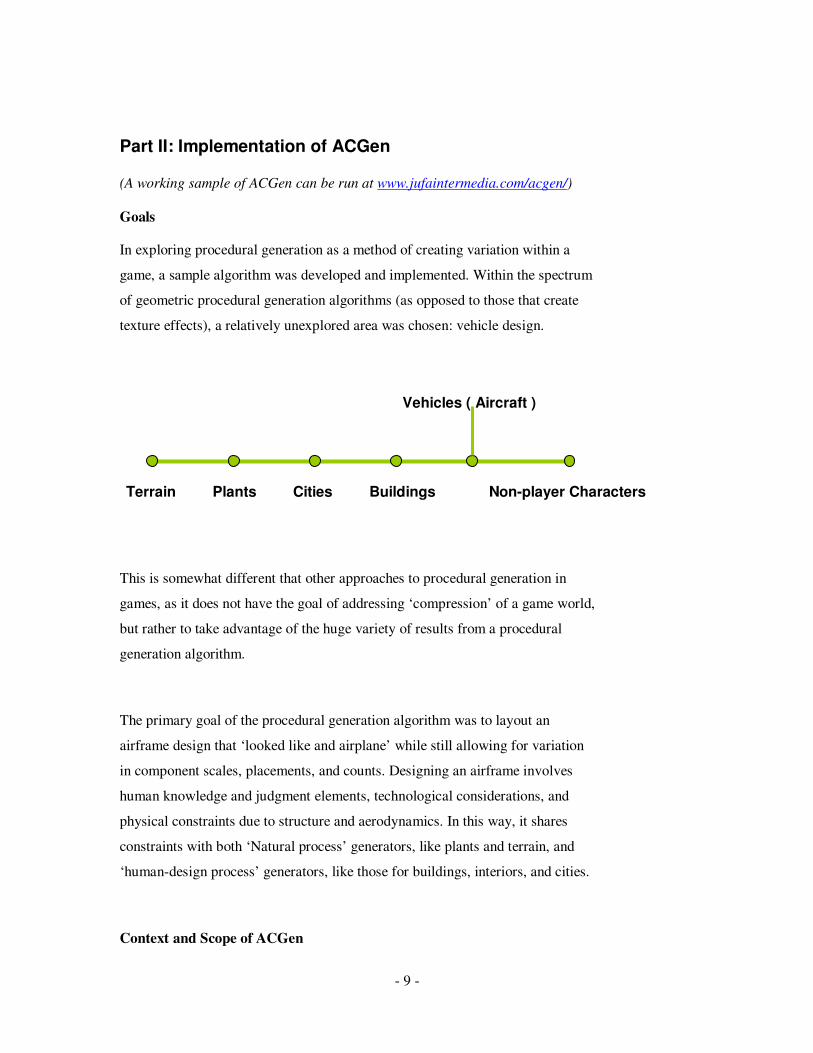
In exploring procedural generation as a method of creating variation within a
game, a sample algorithm was developed and implemented. Within the spectrum
of geometric procedural generation algorithms (as opposed to those that create
texture effects), a relatively unexplored area was chosen: vehicle design.
This is somewhat different that other approaches to procedural generation in
games, as it does not have the goal of addressing ‘compression’ of a game world,
but rather to take advantage of the huge variety of results from a procedural
generation algorithm.
The primary goal of the procedural generation algorithm was to layout an
airframe design that ‘looked like and airplane’ while still allowing for variation
in component scales, placements, and counts. Designing an airframe involves
human knowledge and judgment elements, technological considerations, and
physical constraints due to structure and aerodynamics. In this way, it shares
constraints with both ‘Natural process’ generators, like plants and terrain, and
‘human-design process’ generators, like those for buildings, interiors, and cities.
Context and Scope of ACGen
Terrain Plants Cities Buildings Non-player Characters
Vehicles ( Aircraft )
- 10 -
The context of ACGen was a hypothetical game engine which developed designs
for in-game aircraft. The goal is to create a diverse ‘fleet’ of similar aircraft that
have physical characteristics which are reflected in flight performance. The link
between the visual look of the aircraft and their performance was considered
important in a game context since players could then have a visual cue to identify
the potential role and capabilities of these constantly varying opponents and
allies. This correlation addresses a desire for a puzzle-solving aspect of game-
play.
For this reason it was decided that the physical layout would be developed
procedurally and performance calculated based on approximated aerodynamic
properties. Performance characteristics could then be filtered to assure a ‘flyable’
aircraft, and in turn used to gauge how A.I. pilots could best use the strengths of
the design (maneuverability, speed, cargo capacity etc.)
Physical Layout
The physical layout of an aircraft included fuselage, fuel tanks, wings, control
surfaces, and engines. A set of assumptions on overall plan-form were made in
order to limit the design space and the number of constraints and rules that would
be required. For example a central, single fuselage was taken common to all
designs and served as a backbone for the remainder of the components.
The components were sequentially positioned, scaled, and attached to one
another based on a simple set of constraints and design rules. For example, all
components had constraints in physical dimensions of maximum width and
height. In addition, constraints in positioning and attachment were implemented.
An outline of the design algorithm is as follows:
1. Scale and position central Fuselage (Fuse0 in code) 2. Scale and position outboard Fuselages ((Fuse1 in code)
3. Generate wing to connect fuselage to outboard Fuselages (wing0)
- 11 -
4. Generate control surfaces either from outboard fuel tanks or from
fuselage (wing1) 5. attach engines to either fuselage or outboard fuel tanks (engine0)
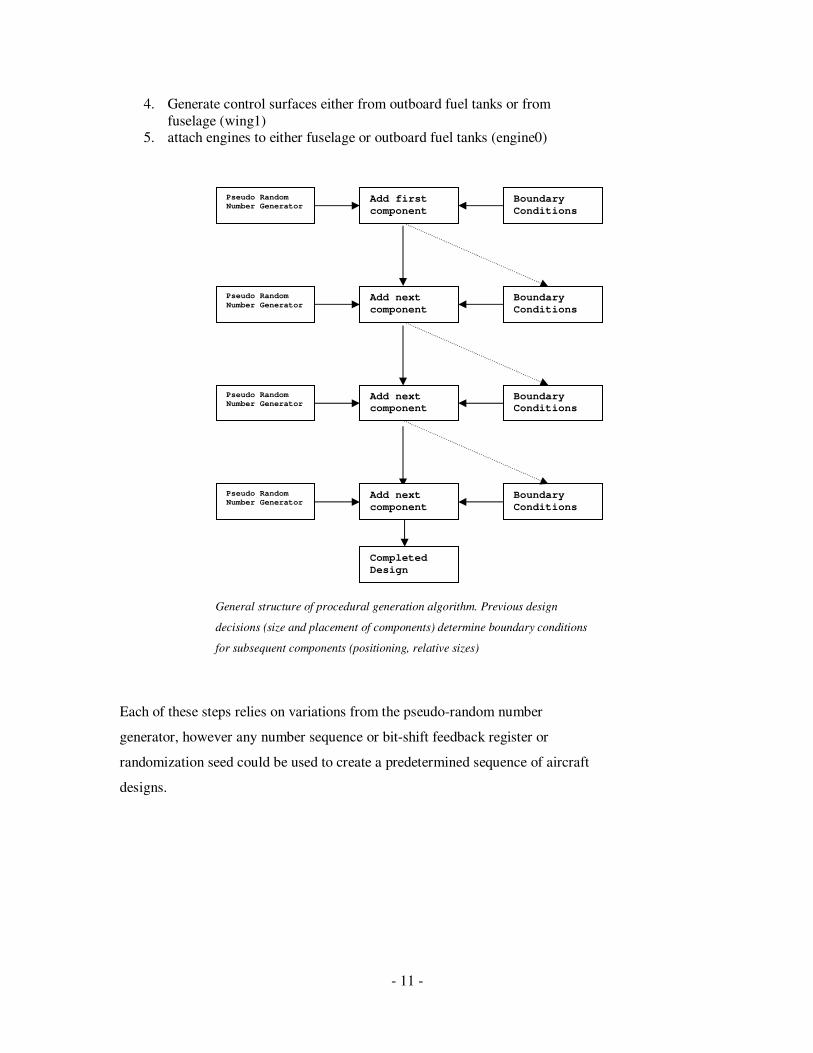
General structure of procedural generation algorithm. Previous design
decisions (size and placement of components) determine boundary conditions
for subsequent components (positioning, relative sizes)
Each of these steps relies on variations from the pseudo-random number
generator, however any number sequence or bit-shift feedback register or
randomization seed could be used to create a predetermined sequence of aircraft
designs.
Pseudo Random Number Generator
Add first
component Generation
Boundary
Conditions
Pseudo Random
Number Generator Add next
component
Procedure
Boundary
Conditions
Pseudo Random Number Generator
Add next component
ure
Boundary Conditions
Pseudo Random Number Generator
Add next
component ure
Boundary
Conditions
Completed
Design
- 12 -
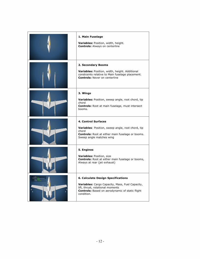
1. Main Fuselage
Variables: Position, width, height. Controls: Always on centerline
2. Secondary Booms
Variables: Position, width, height. Additional constraints relative to Main fuselage placement.
Controls: Never on centerline
3. Wings
Variables: Position, sweep angle, root chord, tip chord
Controls: Root at main fuselage, must intersect booms.
4. Control Surfaces
Variables: Position, sweep angle, root chord, tip chord
Controls: Root at either main fuselage or booms. Sweep angle matches wing
5. Engines
Variables: Position, size Controls: Root at either main fuselage or booms,
Always at rear (jet exhaust)
6. Calculate Design Specifications
Variables: Cargo Capacity, Mass, Fuel Capacity, lift, thrust, rotational moments
Controls: Based on aerodynamic of static flight condition.
- 13 -
Sample Pseudo-Code for Generation of The Wing
// Generate Wing
Place the wing root at the Main fuselage Y-axis
Place wing root leading edge randomly along fuselage Y-axis
using PRNG
Determine wing leading edge sweep to intersect random point
on secondary fuselage
Select wing-span using PRNG
Select wing chord at root using PRNG
Select wing chord at tip using PRNG
Draw outline of wing based on the resulting four x,y
coordinates
//calculate flight parameters
Aircraft Wing Total Lift = area of wing (trapezoid)
Aircraft Center of Lift = point on y-axis 40% from the
furthest forward part of the wing to the furthest to the
rear.
Results
By selecting a procedure which mimics the one method of designing real aircraft,
ACGen successfully produced a wide variety of airframe configurations and
calculated airframe lifts, loads, and moments. With tuning of scaling and
positioning boundary values, a wide variety of ‘families’ of airframes could be
generated, and outliers (airframes that did not look ‘right’ to a viewer) could be
minimized.
Performance
A goal was to provide perceptually instant generation, as the algorithm was not
processor intensive. Generation times were under 200ms on a Pentium 4-class PC
running Windows XP, even considering the low performance of the scripting
language used (Actionscript 2.0, FlashPlayer 9) when compared with native
compiled code.
- 14 -
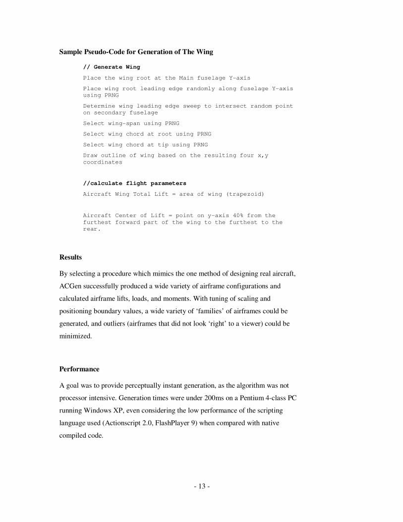
Part III: Further Development
Although boundary values could be successfully tunes to produce a high yield of
believable airframes, additional hierarchical control loops could be implemented
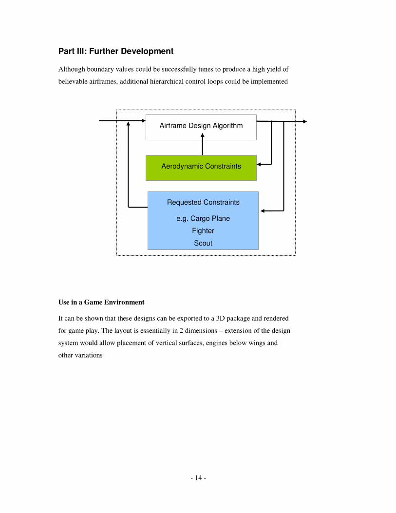
Use in a Game Environment
It can be shown that these designs can be exported to a 3D package and rendered
for game play. The layout is essentially in 2 dimensions – extension of the design
system would allow placement of vertical surfaces, engines below wings and
other variations
Aerodynamic Constraints
Airframe Design Algorithm
Requested Constraints
e.g. Cargo Plane
Fighter
Scout
- 15 -
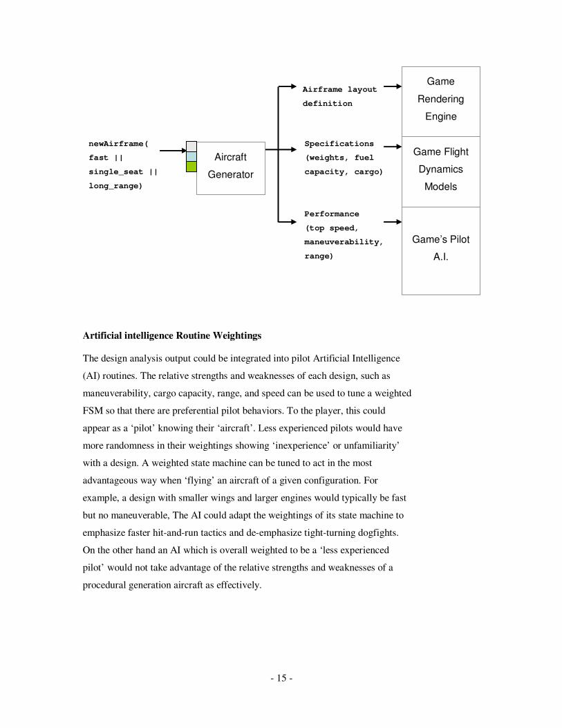
Artificial intelligence Routine Weightings
The design analysis output could be integrated into pilot Artificial Intelligence
(AI) routines. The relative strengths and weaknesses of each design, such as
maneuverability, cargo capacity, range, and speed can be used to tune a weighted
FSM so that there are preferential pilot behaviors. To the player, this could
appear as a ‘pilot’ knowing their ‘aircraft’. Less experienced pilots would have
more randomness in their weightings showing ‘inexperience’ or unfamiliarity’
with a design. A weighted state machine can be tuned to act in the most
advantageous way when ‘flying’ an aircraft of a given configuration. For
example, a design with smaller wings and larger engines would typically be fast
but no maneuverable, The AI could adapt the weightings of its state machine to
emphasize faster hit-and-run tactics and de-emphasize tight-turning dogfights.
On the other hand an AI which is overall weighted to be a ‘less experienced
pilot’ would not take advantage of the relative strengths and weaknesses of a
procedural generation aircraft as effectively.
Aircraft
Generator
newAirframe(
fast ||
single_seat ||
long_range)
Airframe layout
definition
Specifications
(weights, fuel
capacity, cargo)
Performance
(top speed,
maneuverability,
range)
Game’s Pilot
A.I.
Game Flight
Dynamics
Models
Game
Rendering
Engine

- 16 -
Flight Dynamics
As calculated in ACGen, the pitch and roll moments as well as lift and thrust
parameters can be used to determine the relative flight dynamics of the airframe.
This could be input into a generic flight dynamics model within the game engine
so that different configuration would have appropriate performance
characteristics. An underpowered airframe would tend to be slower and one with
a large roll moment would tend to have more sluggish maneuverability in
turning.
The correlation between airframe configuration and performance
Applications for Education
Learning in an interactive environment have potential advantages in retaining an
understanding when compared to passive learning (reading, watching linear
videos). The ACGen core could be modified to provide a simulation that allows a
user to see the effects of their design decisions in an aerodynamic context. The
procedural generation process could allow for user input in several areas with a
different learning goal emphasized in each. Some examples include:
Game: Head-to-Head Designs
Goal: What gives an aircraft its flight characteristics?
In this application, the learner would ultimately be able to discuss why a
given airframe condition could or could not be made into a feasible
aircraft based on its layout. ACGen would generate a two side-by-side
designs each with one parameter varied and the remainder held constant
with respect to one another. The learner would be prompted with an
appropriate series of question relevant to difference. For example, wing
area may be varied between design 1 and 2. ACGen would analyze the
relative difference in wing lift and therefore cargo capacity, maximum
speed and other affected parameters. The learner would be prompted
with questions such as, “which design would have a greater maximum

- 17 -
speed?”, or “Which design would have greater range?”. This would
present the learner with a correlation between the varied parameter and
the impact on aerodynamics. Higher skill-levels could have multiple
parameters varied.
Applications for Artists
The surprising variety of airframe configurations that can be generated in a short
time could contribute to the creative process in game development. Rather than
starting from historical aircraft designs or a blank screen, designers could use
applications such as this to provide a set of potential configurations that can be
categorized and rated. These could seed further design development and act as an
automated ‘brain storm’
An application based on this could allow the artist to select broad parameters of
the design, such as boundary sizes of engines, wings, and general libraries of
components. The resulting designs could be exported in a Collada or other open
3D standard for further refinement in Maya, Blender, or a similar environment.
A separate feature may be a directed designer, which splits the display into areas
for two or four design – the user could select their preferred variation from these,
and further iterations of the design algorithm would be progressively smaller
refinements of those original parameters. This would allow the designer to direct
the creative process without explicitly modifying elements of the design.
Lessons learned
Algorithm Design Procedure: What Makes An “Airplane”?
Several approaches can be taken to creating a procedural design engine.
Questions to be answered can include:
• The context in which the designs are generated? Is there a real-time or
memory constraint?
• How much complexity is required from the model being generated?
- 18 -
• Have intangible qualities been properly quantified? (Realism, fidelity to
what exists in reality)
• Does the design need to meet certain specific criteria of success?
• Does satisfaction of each of the individual criteria on their own merit still
result in an acceptable design, or do hierarchical feedback controls need
to be implemented?
• Is there a budget for which different design elements compete?
• Do the controls and criteria for success still allow for the desired
diversity of design?
What “Looks Right”
Human preconceptions from experience seem to operate on an ‘exceptions’ level,
meaning that when an aircraft design does not look the way it is expected to from
experience, it is immediately apparent. This may be due to the pattern-matching
ability of the brain. Kelly Johnston was quoted to say “if it looks beautiful, it will
fly”. The same applies here, and the rules of the design procedure must be tuned
carefully so that as many designs as possible fall within what is considered
“valid”.
Tuning Parameters
Parameters that determine the constraints of a synthesized design must be
carefully controlled to get a reasonable ‘yield’ of believable products. In the
sample application, ratios of fuselage length versus width, tapering of wings and
sweep angles were tuned considerably by hand to increase “yield”. The
disadvantage is that this also constrains the design space, reducing the overall
variety of design. A careful balance must be made between variation and “yield”.
Summary and Conclusion
- 19 -
Based on these experiments using developing and using ACGen, advantages and
caveats of using procedural generation have been noted.
It is critical to assure that the generation algorithm is testing for and designing
around the right constraints. This typically leads to higher complexity for more
fidelity and a procedural generation algorithm that becomes more and more like a
simulation system. Supervisory control loops and hierarchical monitoring of the
process can prevent outliers that are not easily ‘tuned out’ by changing constraint
numbers, For example, it is simpler and more effective to accept a certain
‘discard’ ratio in design rather than reduce the size of the total design-space to
eliminate the possibility of outliers.
Without sufficient constraints, procedural generation for gaming may not be
reliable or believable, however once the algorithm is working within reasonable
constraints the variety and variation is striking. There is a correlation between the
look of the new aircraft and its performance. In a gaming situation this is a vital
cue for players, adding to the realism of the situation (bombers are big, fighters
are small etc). Game play can be enhanced with the challenge of the player
solving the puzzle of visual configuration and performance.
This procedural generation algorithm can be used as a tool for education or
creative work. Equations for performance are based on aerodynamic rules and if
tuned or made more realistic, the designer could be a training tool for estimating
performance characteristics of a given configuration. Alternatively, the design or
design synthesis parameters could be changed by the used as part of a challenge
to make an optimal cargo plane or fighter. ACGen could also be a basis for a
creative ‘brainstorm’ tool. The designs generated could provide new concepts in
layout and design that may not have been lost in a ‘blank page’ design process.
Procedural generation, with carefully considered constraints, controls and process
can yield a surprising diversity of outputs that match desired patterns while being

- 20 -
individually unique. The process can be applied to vehicle design, and by
extension can potentially be used to emulate the human engineering design
process.
- 21 -
Sources and References
Published
[1] E. R. Tufte, Visual Explanations: Images and Quantities, Evidence and
Narrative.
[2] Kelly, G. and McCabe, H. 2006. Interactive generation of cities for real-time
applications. In ACM SIGGRAPH 2006 Research Posters (Boston,
Massachusetts, July 30 - August 03, 2006). SIGGRAPH '06. ACM, New York,
NY, 44. DOI= http://doi.acm.org/10.1145/1179622.1179673
[3] Prachyabrued, M., Roden, T. E., and Benton, R. G. 2007. Procedural
generation of stylized 2D maprocedural generation. In Proceedings of the
international Conference on Advances in Computer Entertainment Technology
(Salzburg, Austria, June 13 - 15, 2007). ACE '07, vol. 203. ACM, New York,
NY, 147-150. DOI= http://doi.acm.org/10.1145/1255047.1255077
[4] Aaron Stanton , “Games That Never Age: The Unrecognized Potential of
Procedural Synthesis”, About.com [Online] Nov-07. Available:
http://nintendo.about.com/library/procedural/blprocedural1.htm
[5] Hahn, E., Bose, P., and Whitehead, A. 2006. Persistent realtime building
interior generation. In Proceedings of the 2006 ACM SIGGRAPH Symposium
on Videogames (Boston, Massachusetts, July 30 - 31, 2006). sandbox '06. ACM,
New York, NY, 179-186. DOI= http://doi.acm.org/10.1145/1183316.1183342
[6] Saturnino Luz, " Intelligent Agents & Games " Trinity College Dublin,
[Online] CS7ET03 Course notes November 2007. Available: httprocedural
generation://www.cs.tcd.ie/courses/msciet/cs7et03/1/
- 22 -
[7] Noam Nisan (editor). Algorithmic Game Theory. Cambridge University
Press, MA, 2007. (Textbook)
[8] Renton, M., Hanan, J., and Kaitaniemi, P. 2003. The inside story: including
physiology in structural plant models. In Proceedings of the 1st international
Conference on Computer Graphics and interactive Techniques in Australasia and
South East Asia (Melbourne, Australia, February 11 - 14, 2003). GRAPHITE '03.
ACM, New York, NY, 95-ff. DOI= http://doi.acm.org/10.1145/604471.604491
[9] Brabazon, A., Silva, A., de Sousa, T. F., O'Neill, M., Matthews, R., and
Costa, E. 2005. Agent-based modelling of product invention. In Proceedings of
the 2005 Conference on Genetic and Evolutionary Computation (Washington
DC, USA, June 25 - 29, 2005). H. Beyer, Ed. GECCO '05. ACM, New York,
NY, 129-136. DOI= http://doi.acm.org/10.1145/1068009.1068027
[10] Perlin, K. 1997. Layered compositing of facial expression. In ACM
SIGGRAPH 97 Visual Proceedings: the Art and interdisciplinary Programs of
SIGGRAPH '97 (Los Angeles, California, United States, August 03 - 08, 1997).
L. Pocock, R. Hopkins, D. Ebert, and J. Crow, Eds. SIGGRAPH '97. ACM, New
York, NY, 226-227. DOI= http://doi.acm.org/10.1145/259081.259313
[11] F. Kenton Musgrave, Craig E. Kolb and Robert S. Mace: The Synthesis and
Rendering
of Eroded Fractal Terrains. Computer Graphics, Volume 23, Number 3, July
1989
Websites
[12] http://multiagent.com/ [13] www.Allegorithmic.com
[14] http://www.planetside.co.uk/terragen/
[15] http://www.noisemachine.com/talk1/1.html [16] http://www.longnow.org/views/essays/articles/ArtFeynman.php

- 23 -
[17]http://mrl.nyu.edu/~perlin/demox/Planet.html
Correspondence and Interviews
[18] Dr. Anthony Whitehead, Carleton University, November 2007
- 24 -
APPENDIX A: Code Listing
import flash.display.BitmapData;
import flash.geom.Rectangle;
import flash.geom.Matrix;
import flash.geom.ColorTransform;
//global variables
var design:MovieClip; //contains main design area
// aircraft performance metrics:
var mass:Number = 0;
var momentX:Number = 0;
var momentY:Number = 0;
var cargo:Number=0;
var fuel:Number = 0;
var lift:Number=0;
var thrust:Number = 0;
var centerLift:Number=0;
var fuse1Mass=0;
var fuse0Mass=0;
//shared airframe design parameters
var sweepSlope:Number=0;
var wing0ChordRoot:Number = 0;
var totalFuseLength:Number;
/*****************************
RULES
Wing root has to start at a fuselage
mass is proportional to fuselage component size (ie total area on
diagram)
engines have weight
thrust is proportional to total engine area
engines cannot be inline on y-axis
fuselages can't overlap
1 fuselage appears at the centerline
engines appear at the rear of a fuselage
---------------------------
algorith implementing design on these rules:
1. place fuselages -
hard limits
+ min 1, max 2
+ length/width ratio between 1:1 and 2:1
+ max length of design area, min of 0.2 design area
probablistic

- 25 -
+ 1st fuse: strong tendency for 1st fuselage element to appear on
CL and be at least 0.5 design max length
+ 2nd fuse: tendency to be at least 0.25 distance from first fuse
element. May not appear
2. Place Wings -
hard limits
+ wing 1: root must touch CL
+ wing 1: must intersect both fuselages
+ wing 2: must intersect fuse 1 and fuselage 2
+ wing 2 to start at a center fuselage or at fuseleage
probablalistic:
+ total wing area should be approximately equal to k* fuselage
area (mass + negative mass)
+ wings may have a size proportionality
+ wing sweep angle tends to be 'backwards'
3. place engines -
hard limits
+ min 1, max 2
+ must be on the end of a fueslage
+ must be same size
probablistic:
if 1 engine, it has a chance of being right on the centerline,
otherwise one engine width away at least.
*/
/*********************************************
placeFuselage0()
place and size center fuselage along centerline
*********************************************/
function placeFuselage0(){
var widthMax:Number = 250;
var widthMin:Number = 100;
var heightMax:Number = 350;
var heightMin:Number = 100;
// place fuse 0 on X-axis:
// place randomly
var p = Math.floor( Math.random() * design.canvas._width );
// apply simple weighting function:
if (p < 1500) p = 0;//preference for central fuselage
design.fuse0._x = p;
design.fuse0._xscale = Math.floor (
Math.random()*(widthMax-widthMin) + widthMin ); //between 50 and
200% width
design.fuse0._yscale = design.fuse0._xscale;
// place randomly
p = Math.floor( Math.random()* 0);
- 26 -
// apply simple weighting function:
//p = p + Math.floor( Math.random()*
design.canvas._height/1.5 );
design.fuse0._y = p;
}
/*********************************************
placeFuselage1()
place two outer fuselages (fuse1) on either
side of center fuselage
*********************************************/
function placeFuselage1(){
var widthMax:Number = 50;
var widthMin:Number = 50;
var heightMax:Number = 20000/design.fuse0._yscale;
//percent
var heightMin:Number = 75;
var minDistance:Number=100; //minimum distance from center
fuselage
var iBuffer:Number=0;
var iterate:Number=0;
// place randomly
iBuffer=0;
var p = Math.max ( Math.floor( Math.random() *
design.canvas._width-100), minDistance );
// apply simple weighting function:
design.fuse1._x = p;
design.fuse1._xscale = Math.floor ( Math.random()*50 + 50
);
design.fuse1._yscale = Math.floor ( Math.random()*
(heightMax-heightMin) + heightMin );
// place randomly
p = Math.floor( Math.random()* design.canvas._height/2 +
design.canvas._height/4);
design.fuse1._y = p;
}
/*********************************************
placeWing0()
draws main wing to intesect fuselage 0 and
fuselage 1. sweep angle determined by wing position
on fuselages and root and tip chords
*********************************************/
function placeWing0(){
var WINGMAXLENTH:Number=500;

- 27 -
var WINGTIPCHORD:Number=Math.floor(Math.random()*100 +
Math.random()*20 + 20);
var WINGROOTCHORD:Number=Math.floor(Math.random()*100 +
Math.random()*100 + 100);
var WINGPOSONFUSE1:Number = Math.random(); //this is a
ratio from 0(front end) to 1(rear)
//wing0ChordRoot = WINGROOTCHORD;
//place wing root of fuse0
design.wing0._x = design.fuse0._x;
//place along length of fuse0:
design.wing0._y = Math.floor(Math.random() *
(design.fuse0._height-design.fuse0._y-
WINGROOTCHORD)+design.fuse0._y);
//createDrawingMC:
design.wing0.createEmptyMovieClip("wing",1000);
//sweep wing0 to intersect fuse1:
with (design.wing0.wing){
lineStyle(1,0x666666,100);
beginFill(0xdddddd,100);
moveTo(0,0);
//determine wing leading edge sweep (line slope):
sweepSlope = (design.fuse1._y-
design.wing0._y+WINGPOSONFUSE1*design.fuse1._height) /
(design.fuse1._x-design.wing0._x);
//determine linear distance between fuse0 and fuse 1:
var d = Math.sqrt ( Math.pow((design.fuse1._y-
design.fuse0._y),2) + Math.pow((design.fuse1._x-
design.fuse0._x),2));
//determine wing length:
var l = Math.min( Math.floor(
Math.random()*(WINGMAXLENTH-d)+d), WINGMAXLENTH);
//determin wingtip endpoint:
var endX = Math.min(l/sweepSlope,WINGMAXLENTH);
var endY = sweepSlope*endX;
//and draw it:
//curveTo(endX/2,endY/3,endX,endY);
lineTo(endX,endY);
lineTo(endX+10,endY+WINGTIPCHORD);
curveTo(0,WINGROOTCHORD*0.75,0,WINGROOTCHORD);
lineTo(0,0);
endFill();
}
//revise performance params:
var tgt:MovieClip=design.wing0;
var partLift =
(WINGROOTCHORD+WINGTIPCHORD)/2*design.wing0._width;
//momentX += tgt._x * partMass;
//momentY += tgt._y + tgt._height/2 * partMass;
//mass+=partMass;
//fuel = partMass*2;
centerLift = tgt._y+0.4*tgt._height;
design.cl._y=centerLift;
lift+=partLift;
//revise performance params:
tgt=design.fuse0;
- 28 -
var partMass:Number = (tgt._width * tgt._height);
momentX +=0;
momentY = (tgt._y + tgt._height/2 - centerLift) * partMass;
mass += partMass;
cargo = partMass;
//revise performance params:
tgt=design.fuse1;
partMass = (tgt._width*tgt._height);
momentX += (tgt._x * partMass);
momentY += (tgt._y + tgt._height/2 - centerLift) *
partMass;
mass+=partMass;
fuel = partMass*2;
}
/*********************************************
placeWing1()
draws secondary wing to start at fuselage 0 or
fuselage 1. Sweep angle determined by wing0 sweep
*********************************************/
function placeWing1()
{
var WINGMAXLENTH:Number=200;
var WINGTIPCHORD:Number=Math.floor(Math.random()*20 +
Math.random()*20 + 25)
var WINGROOTCHORD:Number=Math.floor(Math.random()*100 +
Math.random()*100 + 25);
var tgtFuse:MovieClip;
//place wing root of fuse0 OR fuse 1
if (Math.random()<0.5){
design.wing1._x = design.fuse0._x;
tgtFuse=design.fuse0;
} else {
design.wing1._x = design.fuse1._x;
tgtFuse=design.fuse1;
}
// place wing along length of fuse0:
iterate=0;
while(iterate<20){
design.wing1._y = Math.floor(Math.random() *
(tgtFuse._height)+tgtFuse._y);
if(design.wing1._y < design.wing0._y ||
design.wing1._y > design.wing0._y + wing0ChordRoot){
iterate=21;
} else {
iterate++;
}
}
//createDrawingMC:
design.wing1.createEmptyMovieClip("wing",1001);
//sweep wing0 to intersect fuse1:
with (design.wing1.wing){
lineStyle(1,0x666666,100);
beginFill(0xeeeeee,100);

- 29 -
moveTo(0,0);
//determine linear distance between fuse0 and fuse 1:
var d = Math.sqrt ( Math.pow((design.fuse1._y-
design.fuse0._y),2) + Math.pow((design.fuse1._x-
design.fuse0._x),2));
//determine wing length:
var l = Math.floor( Math.random()*(WINGMAXLENTH-
d)+d);
//determin wingtip endpoint:
var endX = l;
//option of reversing the tails if on fuse0
if(1 != 1) {
endX = -endX;
sweepSlope = -sweepSlope;
}
var endY = sweepSlope*endX;
//and draw it:
lineTo(endX,endY);
lineTo(endX+10,endY+WINGTIPCHORD);
lineTo(0,WINGROOTCHORD);
lineTo(0,0);
endFill();
}
//revise performance params:
var tgt:MovieClip=design.wing1;
var partLift = (WINGROOTCHORD+WINGTIPCHORD)/2*tgt._width;
lift+=partLift;
momentY += (tgt._y + 0.4 * tgt._height -centerLift)*
partLift;
}
//------------ END placeWing1 --------------
/*********************************************
placeEngines()
final step in airframe genereation
places engine on airframe
*********************************************/
function placeEngines(){
//determine where and how many
var maxScale=125;
var minScale=75;
var numEngines:Number=0;
engineScale = Math.floor(Math.random()*(maxScale-
minScale)+minScale);
if (Math.random()<0.5){
tgt = design.fuse0;
numEngines = 1;
} else {
tgt = design.fuse1;
numEngines = 2;
}
design.engine0._x = tgt._x;
design.engine0._y = tgt._y+tgt._height;
design.engine0._xscale = engineScale;
design.engine0._yscale = engineScale;
thrust = numEngines * engineScale * 100;
//revise performance params:

- 30 -
tgt=design.engine0;
var partMass:Number = (tgt._width * tgt._height);
momentX += partMass * tgt._x;
momentY += (tgt._y + tgt._height/2 - centerLift) * partMass
* numEngines;
mass += partMass;
design.cg._y=momentY/mass+centerLift;
}
/*********************************************
mirror()
renders the design as a bitmap
*********************************************/
function mirror(){
if(1==1){
im = new BitmapData(1000,1000,true,0);
ref=this.createEmptyMovieClip("mirror",2000);
ref._x=0
ref._y=100;
ref.attachBitmap(im,1000);
}
var myMatrix:Matrix = new Matrix();
var translateMatrix:Matrix = new Matrix();
translateMatrix.translate(500, 0);
myMatrix.concat(translateMatrix);
this.im.draw(design,myMatrix);
var myMatrix2:Matrix = new Matrix();
myMatrix2.scale(-1, 1);
var translateMatrix2:Matrix = new Matrix();
translateMatrix2.translate(500, 0);
myMatrix2.concat(translateMatrix2);
this.im.draw(design,myMatrix2);
}
/*********************************************
calcPerformance()
determine base performance factors for airframe
*********************************************/
function calcPerformance(){
var n:Number=100; //for other graphs
var k:Number=30000; //for moments bar graph
//adjust y moment for CLift:
- 31 -
bar0.lbl.text = "moment X "+momentX;
bar0.bar._width = momentX/k;
bar1.lbl.text = "moment Y "+momentY;
bar1.bar._width = momentY/k;
bar2.lbl.text = "Cargo Capacity "+fuel;
bar2.bar._width = cargo/n;
bar3.lbl.text = "Fuel "+fuel;
bar3.bar._width = fuel/n;
bar4.lbl.text = "Lift "+lift;
bar4.bar._width = lift/n;
bar5.lbl.text = "Thrust "+thrust;
bar5.bar._width = thrust/n;
}
/*********************************************
clearPerformance()
Resets performance parameters on each generation
*********************************************/
function clearPerformance(){
mass = 0;
momentX = 0;
momentY = 0;
cargo=0;
fuel = 0;
lift=0;
thrust = 0;
centerLift=0;
}
/*********************************************
classifyDesign()
*********************************************/
function classifyDesign(){
}
/*********************************************
void init(void)
main PG function
*********************************************/
function init(){
clearPerformance();
resetPositions();
placeFuselage0();
placeFuselage1();
placeWing0();
placeWing1();
placeEngines();
mirror();
calcPerformance();
- 32 -
}
/*********************************************
In ActionScript this interrupt substitutes for main()
*********************************************/
onEnterFrame = function(){
onEnterFrame=null;
btn_refresh.onRelease=function(){
init();
}
init();
}


