Christopher E. Hughes, Dale E. Van Zante, and James D. Heidmann Glenn Research Center, Cleveland, Ohio Aircraft Engine Technology for Green Aviation to Reduce Fuel Burn NASA/TM—2013-217690 November 2013 AIAA–2011–3531 https://ntrs.nasa.gov/search.jsp?R=20140003870 2018-02-10T21:20:26+00:00Z
Transcript
Christopher E. Hughes, Dale E. Van Zante, and James D. HeidmannGlenn Research Center, Cleveland, Ohio
Aircraft Engine Technology for Green Aviation to Reduce Fuel Burn
Since its founding, NASA has been dedicated to the advancement of aeronautics and space science. The NASA Scientific and Technical Information (STI) program plays a key part in helping NASA maintain this important role.
The NASA STI Program operates under the auspices of the Agency Chief Information Officer. It collects, organizes, provides for archiving, and disseminates NASA’s STI. The NASA STI program provides access to the NASA Aeronautics and Space Database and its public interface, the NASA Technical Reports Server, thus providing one of the largest collections of aeronautical and space science STI in the world. Results are published in both non-NASA channels and by NASA in the NASA STI Report Series, which includes the following report types: • TECHNICAL PUBLICATION. Reports of
completed research or a major significant phase of research that present the results of NASA programs and include extensive data or theoretical analysis. Includes compilations of significant scientific and technical data and information deemed to be of continuing reference value. NASA counterpart of peer-reviewed formal professional papers but has less stringent limitations on manuscript length and extent of graphic presentations.
• TECHNICAL MEMORANDUM. Scientific
and technical findings that are preliminary or of specialized interest, e.g., quick release reports, working papers, and bibliographies that contain minimal annotation. Does not contain extensive analysis.
• CONTRACTOR REPORT. Scientific and
technical findings by NASA-sponsored contractors and grantees.
• CONFERENCE PUBLICATION. Collected papers from scientific and technical conferences, symposia, seminars, or other meetings sponsored or cosponsored by NASA.
• SPECIAL PUBLICATION. Scientific,
technical, or historical information from NASA programs, projects, and missions, often concerned with subjects having substantial public interest.
• TECHNICAL TRANSLATION. English-
language translations of foreign scientific and technical material pertinent to NASA’s mission.
Specialized services also include creating custom thesauri, building customized databases, organizing and publishing research results.
For more information about the NASA STI program, see the following:
• Access the NASA STI program home page at http://www.sti.nasa.gov
• E-mail your question to [email protected] • Fax your question to the NASA STI
Information Desk at 443–757–5803 • Phone the NASA STI Information Desk at 443–757–5802 • Write to:
STI Information Desk NASA Center for AeroSpace Information 7115 Standard Drive Hanover, MD 21076–1320
Christopher E. Hughes, Dale E. Van Zante, and James D. HeidmannGlenn Research Center, Cleveland, Ohio
Aircraft Engine Technology for Green Aviation to Reduce Fuel Burn
NASA/TM—2013-217690
November 2013
AIAA–2011–3531
National Aeronautics andSpace Administration
Glenn Research Center Cleveland, Ohio 44135
Prepared for the3rd Atmospheric and Space Environments Conferencesponsored by the American Institute of Aeronautics and AstronauticsHonolulu, Hawaii, June 27–30, 2011
Available from
NASA Center for Aerospace Information7115 Standard DriveHanover, MD 21076–1320
National Technical Information Service5301 Shawnee Road
Alexandria, VA 22312
Available electronically at http://www.sti.nasa.gov
Trade names and trademarks are used in this report for identification only. Their usage does not constitute an official endorsement, either expressed or implied, by the National Aeronautics and
Space Administration.
Level of Review: This material has been technically reviewed by technical management.
NASA/TM—2013-217690 1
Aircraft Engine Technology for Green Aviation to Reduce Fuel Burn
Christopher E. Hughes, Dale E. Van Zante, and James D. Heidmann
National Aeronautics and Space Administration Glenn Research Center Cleveland, Ohio 44135
Abstract The NASA Fundamental Aeronautics Program Subsonic Fixed Wing Project and Integrated Systems
Research Program Environmentally Responsible Aviation Project in the Aeronautics Research Mission Directorate are conducting research on advanced aircraft technology to address the environmental goals of reducing fuel burn, noise and NOx emissions for aircraft in 2020 and beyond. Both Projects, in collaborative partnerships with U.S. Industry, Academia, and other Government Agencies, have made significant progress toward reaching the N+2 (2020) and N+3 (beyond 2025) installed fuel burn goals by fundamental aircraft engine technology development, subscale component experimental investigations, full scale integrated systems validation testing, and development validation of state of the art computation design and analysis codes. Specific areas of propulsion technology research are discussed and progress to date.
Introduction In 2006, an Executive Order was signed by the President of the United States issuing a National
Aeronautics Research and Development Policy and Plan (Ref. 1), part of which was aimed at addressing environmental concerns in the U.S. Aviation System. Goals and objectives were established for reductions in fuel burn, noise and NOx emissions for future aircraft to address their environmental impact. The NASA Aeronautics Research Mission Directorate (ARMD) established the Fundamental Aeronautics Program (FAP) to develop advanced technologies to address these goals. Four distinct projects were created, one of which was the Subsonic Fixed Wing Project (SFW), part of whose mission was to develop advanced propulsion technologies for subsonic aircraft in a five to fifteen year timeframe, also known as N+1 to N+2 generation. Today, the SFW Project, together with research partners from Industry, Academia, and other Government Agencies, is focusing on developing technologies for the N+3 generational timeframe, or beyond 2025 (Refs. 2 and 3). These are fundamental technologies in the Technology Readiness Level (TRL) of 1 to 3 range (definition of Technology Readiness Levels are given in the Appendix) that show potential benefits to address the Project environmental goals when incorporated to systems level applications. The SFW Project is also tasked to develop and validate computer prediction tools at both the component and system level application for future application to advanced aircraft system designs.
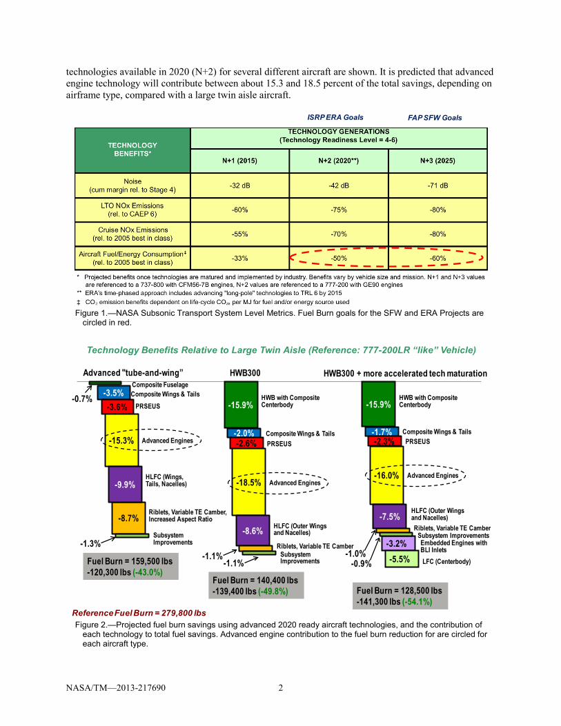
The NASA ARMD subsequently also established the Integrated Systems Research Program (ISRP) to carry forward to large scale, integrated system demonstrations the technologies developed under SFW that show potential benefit for addressing the environmental goals. The Environmentally Responsible Aviation Project (ERA) was created in 2009 to develop those integrated system demonstrations to the TRL range of 4 to 6 in the 2020 to 2025 timeframe, or N+2 generation of aircraft systems (Ref. 4). In order to accomplish these complex demonstrations, ERA too relies strongly on successfully meeting the environmental goals by conducting research with Industry, Academia and Government Agencies through cost share partnerships, research collaborations, and NASA Research Announcements. In Figure 1, the Subsonic Transport System Level Metrics are shown, outlining the environmental fuel burn, noise and emissions reduction goals, the time frame for achieving them, and the baseline defined for comparing with new technologies. And in Figure 2, the fuel burn savings potential using advanced aircraft
NASA/TM—2013-217690 2
technologies available in 2020 (N+2) for several different aircraft are shown. It is predicted that advanced engine technology will contribute between about 15.3 and 18.5 percent of the total savings, depending on airframe type, compared with a large twin aisle aircraft.
Figure 1.—NASA Subsonic Transport System Level Metrics. Fuel Burn goals for the SFW and ERA Projects are
circled in red.
Figure 2.—Projected fuel burn savings using advanced 2020 ready aircraft technologies, and the contribution of
each technology to total fuel savings. Advanced engine contribution to the fuel burn reduction for are circled for each aircraft type.
ISRP ERA Goals FAP SFW Goals
Reference Fuel Burn = 279,800 lbs
-15.9%HWB with CompositeCenterbody
-3.2%-5.5%
Embedded Engines withBLI InletsLFC (Centerbody)
-8.7%
-3.5%-3.6%
-15.3%
-9.9%
Composite FuselageComposite Wings & Tails
PRSEUS
Advanced Engines
HLFC (Wings, Tails, Nacelles)
Riblets, Variable TE Camber, Increased Aspect Ratio
Subsystem Improvements
-2.0% Composite Wings & Tails-2.6% PRSEUS
-18.5% Advanced Engines
-8.6% HLFC (Outer Wings and Nacelles)
Riblets, Variable TE CamberSubsystem Improvements
-15.9%
-1.7%-2.3%
-16.0%
-7.5%Riblets, Variable TE Camber
Subsystem Improvements
Technology Benefits Relative to Large Twin Aisle (Reference: 777-200LR “like” Vehicle)
Advanced "tube-and-wing” HWB300 HWB300 + more accelerated tech maturation
This paper will provide overview of the advanced technology concepts related to engine cycle and power core technologies currently being investigated under the NASA SFW and ERA Projects.
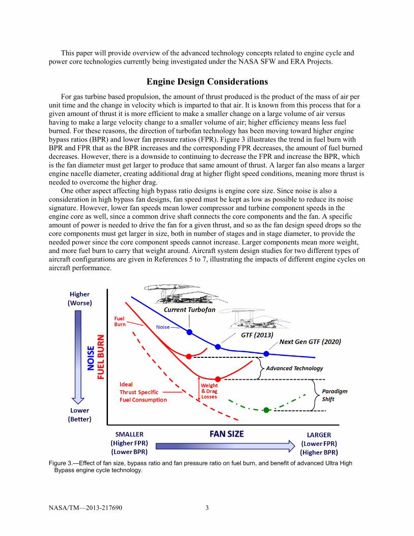
Engine Design Considerations For gas turbine based propulsion, the amount of thrust produced is the product of the mass of air per
unit time and the change in velocity which is imparted to that air. It is known from this process that for a given amount of thrust it is more efficient to make a smaller change on a large volume of air versus having to make a large velocity change to a smaller volume of air; higher efficiency means less fuel burned. For these reasons, the direction of turbofan technology has been moving toward higher engine bypass ratios (BPR) and lower fan pressure ratios (FPR). Figure 3 illustrates the trend in fuel burn with BPR and FPR that as the BPR increases and the corresponding FPR decreases, the amount of fuel burned decreases. However, there is a downside to continuing to decrease the FPR and increase the BPR, which is the fan diameter must get larger to produce that same amount of thrust. A larger fan also means a larger engine nacelle diameter, creating additional drag at higher flight speed conditions, meaning more thrust is needed to overcome the higher drag.
One other aspect affecting high bypass ratio designs is engine core size. Since noise is also a consideration in high bypass fan designs, fan speed must be kept as low as possible to reduce its noise signature. However, lower fan speeds mean lower compressor and turbine component speeds in the engine core as well, since a common drive shaft connects the core components and the fan. A specific amount of power is needed to drive the fan for a given thrust, and so as the fan design speed drops so the core components must get larger in size, both in number of stages and in stage diameter, to provide the needed power since the core component speeds cannot increase. Larger components mean more weight, and more fuel burn to carry that weight around. Aircraft system design studies for two different types of aircraft configurations are given in References 5 to 7, illustrating the impacts of different engine cycles on aircraft performance.
Figure 3.—Effect of fan size, bypass ratio and fan pressure ratio on fuel burn, and benefit of advanced Ultra High
Bypass engine cycle technology.
NASA/TM—2013-217690 4
The result of these design constraints are shown in the fuel burn trend line in red in Figure 3. It shows that a practical limit is finally reached as the trend line reaches a low point and then turns up again as the fan size increases, meaning more fuel burned. The fan size has gotten so large that the added weight of the fan and nacelle, the additional nacelle drag, and the increase in core weight overcomes the fuel advantage of the higher BPR and lower FPR design. What is needed is a paradigm shift in propulsion technology to extend the fuel burn advantage trend line with increasing BPR. NASA SFW and ERA Projects along with their research Partners in Industry, Academia and Other Government Agencies have been conducting advance propulsion technology research to accomplish that goal.
Engine Technologies The following sections will describe the aircraft engine technologies being explored by the NASA
SFW and ERA Projects to achieve the installed fuel burn metrics described in Figure 1.
Geared Turbofan Technology As was shown in Figure 3, a minimum point is reached in the fuel burn trend line for a given engine
cycle where increasing the engine BPR beyond a certain point leads to negative results with higher fuel burn as the increase in engine weight and size overcome the benefits of a high bypass ratio engine cycle. With current technology, this is a result of the conventional high bypass engine cycle known as direct drive, where the fan and core components are rotating on the same shaft. In the direct drive engine, the fan and core components (compressor and turbine) operate at the same rotation speed; thus the system is constrained by the component with the lowest speed, which is the fan in the propulsor. The core must run at slower, less efficient speeds for a lower speed fan design. As discussed earlier, this means more compressor and turbine stages are needed to produce the power required to drive the fan and get the required thrust at a given operating speed, resulting in more engine weight. In Figure 3, the answer to getting lower fuel burn is to shift the point of maximum benefit further down on fuel burn trend line by introducing advanced technologies to achieve a paradigm shift. This means the fan BPR and thus efficiency continues increasing; but it also means the fan PR decreases while the fan diameter increases for the required thrust. The Geared Turbofan (GTF) engine cycle introduced by Pratt & Whitney (P&W) is one of these advanced technologies that enable this paradigm shift. In the GTF architecture, the fan and the core components are separated by a gear system. The gear system allows the fan and the core to operate at different, more efficient speeds. The core can then operate more efficiently and produce a given thrust level at the fan with fewer compressor and turbine stages compared to a direct drive engine, thereby reducing the engine weight and the fuel required to carry that weight around on the aircraft. The advantages of the GTF engine cycle in terms of fan efficiency compared with the conventional turbofan cycle is shown in Figure 4.
The first generation GTF was developed by P&W in partnership with NASA (Refs. 8 to 14). Scale model wind tunnel tests to validate predicted aerodynamic, acoustic and aeroelastic design characteristics were conducted in the NASA Glenn 9- by 15-Foot Low Speed Wind Tunnel in 2006 Figure 5, top) (Ref 15). The first full scale engine demonstration of the GTF engine cycle technology was successfully completed by P&W in 2008 (Figure 5, bottom), and followed shortly thereafter by the first flight test demonstration of the GTF by P&W in the same year (Figure 5, middle). The first generation GTF is considered an N+1 technology (TRL 6 by 2015) which P&W plans to enter into service with aircraft manufacturers in 2013. In Figure 6, the technology areas investigated collaboratively by NASA and P&W in the developing of the first generation GTF are shown and include the low speed, low pressure ratio fan, fan gear system, low emissions combustor, and high speed, compact, low pressure spool. These technologies allowed the engine BPR to reach the Ultra High Bypass (UHB) ratio range of 12 or greater, while allowing the FPR to be reduced to between 1.3 and 1.4 to achieve higher fan efficiencies. In Figure 7 (left), the projected reductions in noise, emissions and fuel burn (a fuel burn reduction of 15 percent) that can be achieved by the GTF engine cycle is compared with a current technology A320 aircraft and V2500 engine combination.
NASA/TM—2013-217690 5
Figure 4.—Trend in Fan Propulsive Efficiency with Fan Pressure Ratio, and range of application for
First P&W flight demonstration of GTF engine in 2008
First P&W GTF full scale engine demonstration in 2008
Scale model GTF fan test in NASA Glenn 9’x15’ low speed wind tunnel in 2006
NASA/TM—2013-217690 6
Figure 6.—NASA/P&W areas of research collaboration for the GTF engine cycle.
Figure 7.—Projected reductions in fuel burn and other environmental emissions with the P&W GTF
engine cycle.
Once again, however, a maximum benefit point will be reached for this level of technology as the design BPR continues to increase and the FPR decreases. A second paradigm shift in technology is needed to extend the beneficial fuel burn tend line (red trend line in Figure 3) to significantly contribute toward achieving the ERA N+2 system level metrics environmental goals (Figure 1). NASA and P&W are again partnering to investigate a second generation of GTF propulsor (fan, stators, and nacelle) technologies to help meet those goals, enabling a BPR up to 18 and a FPR between 1.25 and 1.3 to be achieved. Figure 7 (right) shows the projected fuel burn benefits the second generation GTF will provide, which is a 25 to 30 percent reduction compared to a current V2500/A320 aircraft combination. Current research plans show the start of a collaborative, second generation GTF fan model test with advanced propulsor technologies in the NASA Glenn 9- by 15-Foot Low Speed Wind Tunnel in late 2011.
Fan Drive Gear SystemGear Ratio ~ 3
Low-SpeedLow-Pressure
High-Bypass-RatioFan
High-Speed,Compact,Low Spool
Low-Emissions Combustor
P&W GTF Gen 1 (2013 EIS)
NOISE -20 EPNdB(cum margin to Ch 4)
LTO NOX -60%(below CAEP 6)
FUEL BURN -15% (rel to A320/V2500)
Projected Based onDemonstrated Technology
P&W GTF Gen 2 (2020 to 2025 EIS)
NOISE -25 EPNdB(cum margin to Ch 4)
LTO NOX -75%(below CAEP 6)
FUEL BURN -25% to 30%(rel to A320/V2500)
Projected Based onDemonstrated Technology
NASA/TM—2013-217690 7
Open Rotor Technology
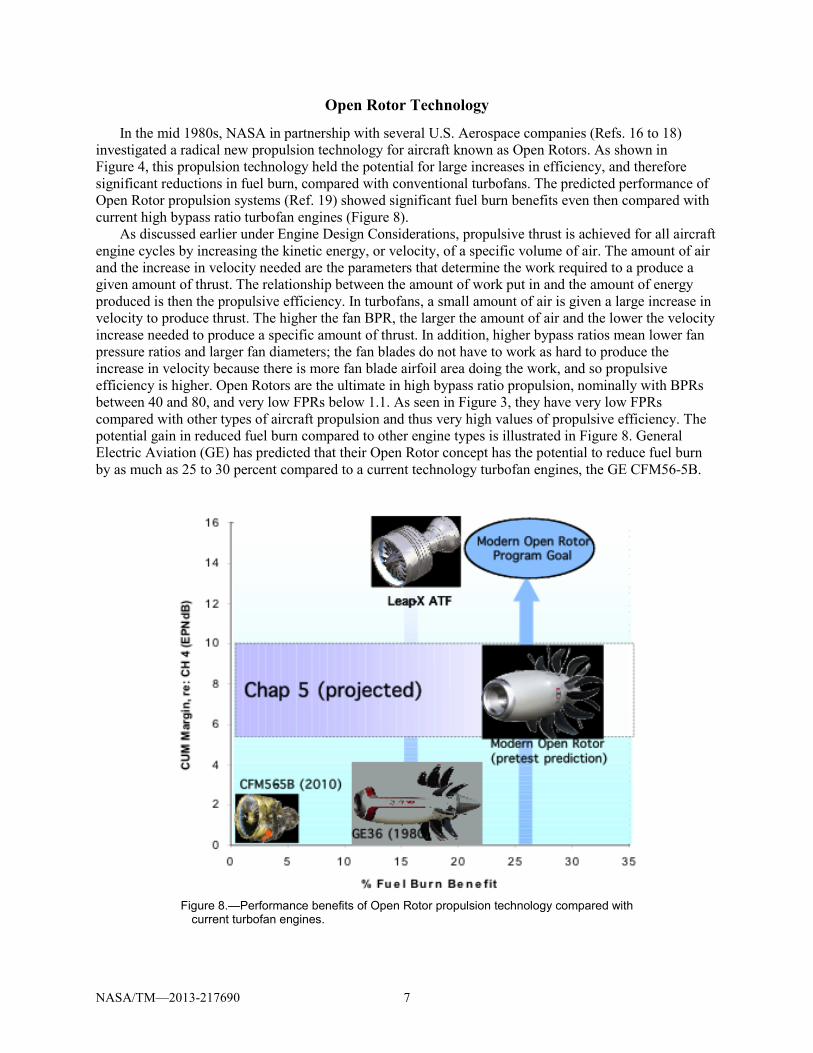
In the mid 1980s, NASA in partnership with several U.S. Aerospace companies (Refs. 16 to 18) investigated a radical new propulsion technology for aircraft known as Open Rotors. As shown in Figure 4, this propulsion technology held the potential for large increases in efficiency, and therefore significant reductions in fuel burn, compared with conventional turbofans. The predicted performance of Open Rotor propulsion systems (Ref. 19) showed significant fuel burn benefits even then compared with current high bypass ratio turbofan engines (Figure 8).
As discussed earlier under Engine Design Considerations, propulsive thrust is achieved for all aircraft engine cycles by increasing the kinetic energy, or velocity, of a specific volume of air. The amount of air and the increase in velocity needed are the parameters that determine the work required to a produce a given amount of thrust. The relationship between the amount of work put in and the amount of energy produced is then the propulsive efficiency. In turbofans, a small amount of air is given a large increase in velocity to produce thrust. The higher the fan BPR, the larger the amount of air and the lower the velocity increase needed to produce a specific amount of thrust. In addition, higher bypass ratios mean lower fan pressure ratios and larger fan diameters; the fan blades do not have to work as hard to produce the increase in velocity because there is more fan blade airfoil area doing the work, and so propulsive efficiency is higher. Open Rotors are the ultimate in high bypass ratio propulsion, nominally with BPRs between 40 and 80, and very low FPRs below 1.1. As seen in Figure 3, they have very low FPRs compared with other types of aircraft propulsion and thus very high values of propulsive efficiency. The potential gain in reduced fuel burn compared to other engine types is illustrated in Figure 8. General Electric Aviation (GE) has predicted that their Open Rotor concept has the potential to reduce fuel burn by as much as 25 to 30 percent compared to a current technology turbofan engines, the GE CFM56-5B.
Figure 8.—Performance benefits of Open Rotor propulsion technology compared with
current turbofan engines.
NASA/TM—2013-217690 8
Figure 9.—Scale model Open Rotor fan model undergoing testing in the NASA Glenn 9- by15-Foot low
speed (left) and 8- by 6-Foot high speed (right) wind tunnels.
Today, with the renewed emphasis on reducing the environmental impact of commercial aircraft, NASA and GE have partnered once again to investigate Open Rotor propulsion for the ERA N+2 generation of aircraft systems. GE has built upon its 1980s experience with the GE36 Program Unducted Fan (UDF), and has taken advantage of the tremendous increases in aerodynamic design capability in computational fluid dynamics, advanced high speed computers, and advanced strong light weight materials technology since the 1980s to develop a new generation of Open Rotors. GE is designing advanced three dimensional fan blade designs and using tailored material construction techniques to optimize the fan blade shapes for maximum performance, as well as minimum noise. An extensive series of tests of a first generation of advanced fan blade technology, sponsored by the SFW and ERA Projects, was conducted at NASA Glenn in 2010. Low speed testing up to Mach number 0.22 was performed in the Glenn 9- by 15-Foot wind tunnel on several fan blade designs to investigate their low speed performance near take-off conditions and at angle of attack. In Figure 9 (left side) a photo of the NASA/GE Open Rotor Propulsion Rig with pylon simulator installed is shown in the 9- by 15-Foot test section. Flow field diagnostics measurements using Phased Array, Particle Image Velocimetry and Pressure/Temperature Sensitive Paint were also made (Refs. 20 and 21) to investigate the interaction of the fan blade rows with each other and with a simulated pylon to characterize installation effects. Currently, NASA and GE are investigating the high speed cruise performance of Open Rotors up to Mach number 0.85 in the Glenn 8’x6’ high speed wind tunnel. A photo of the NASA Open Rotor Drive Rig and GE Historical Baseline blade set is shown on the right hand side in Figure 9.
Preliminary test results show that GE has successfully demonstrated both aero performance and noise reduction objectives for this first generation of fan blade design (Refs. 22 and 23). Preliminary wind tunnel results have validated GE performance predictions of the high propulsive efficiency that can be achieved with Open Rotor propulsion and advanced 3D fan blade designs. Future NASA/GE collaborative testing of a second generation of Open Rotor fan blade designs at NASA Glenn, in partnership with ERA and the Federal Aviation Administration (FAA) Continuous Low Energy Efficient Noise (CLEEN) Program, is planned for mid 2011 to achieve further increases in performance as well as reduce the noise signature of the Open Rotor system toward comparable turbofan levels. Figure 7 shows in the upper right hand corner the ultimate goal of the GE Open Rotor program for fuel burn and noise reductions.
NASA/TM—2013-217690 9
Engine Core Technology
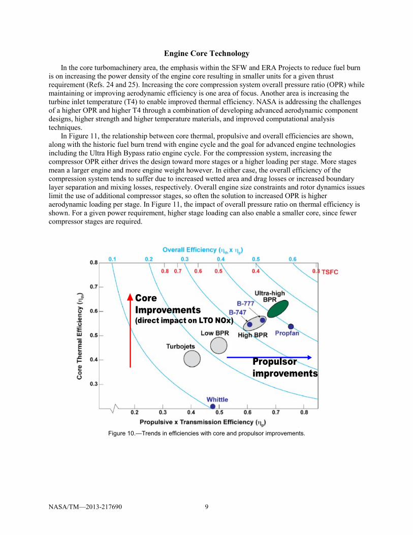
In the core turbomachinery area, the emphasis within the SFW and ERA Projects to reduce fuel burn is on increasing the power density of the engine core resulting in smaller units for a given thrust requirement (Refs. 24 and 25). Increasing the core compression system overall pressure ratio (OPR) while maintaining or improving aerodynamic efficiency is one area of focus. Another area is increasing the turbine inlet temperature (T4) to enable improved thermal efficiency. NASA is addressing the challenges of a higher OPR and higher T4 through a combination of developing advanced aerodynamic component designs, higher strength and higher temperature materials, and improved computational analysis techniques.
In Figure 11, the relationship between core thermal, propulsive and overall efficiencies are shown, along with the historic fuel burn trend with engine cycle and the goal for advanced engine technologies including the Ultra High Bypass ratio engine cycle. For the compression system, increasing the compressor OPR either drives the design toward more stages or a higher loading per stage. More stages mean a larger engine and more engine weight however. In either case, the overall efficiency of the compression system tends to suffer due to increased wetted area and drag losses or increased boundary layer separation and mixing losses, respectively. Overall engine size constraints and rotor dynamics issues limit the use of additional compressor stages, so often the solution to increased OPR is higher aerodynamic loading per stage. In Figure 11, the impact of overall pressure ratio on thermal efficiency is shown. For a given power requirement, higher stage loading can also enable a smaller core, since fewer compressor stages are required.
Figure 10.—Trends in efficiencies with core and propulsor improvements.
Core Improvements(direct impact on LTO NOx)
Propulsorimprovements
NASA/TM—2013-217690 10
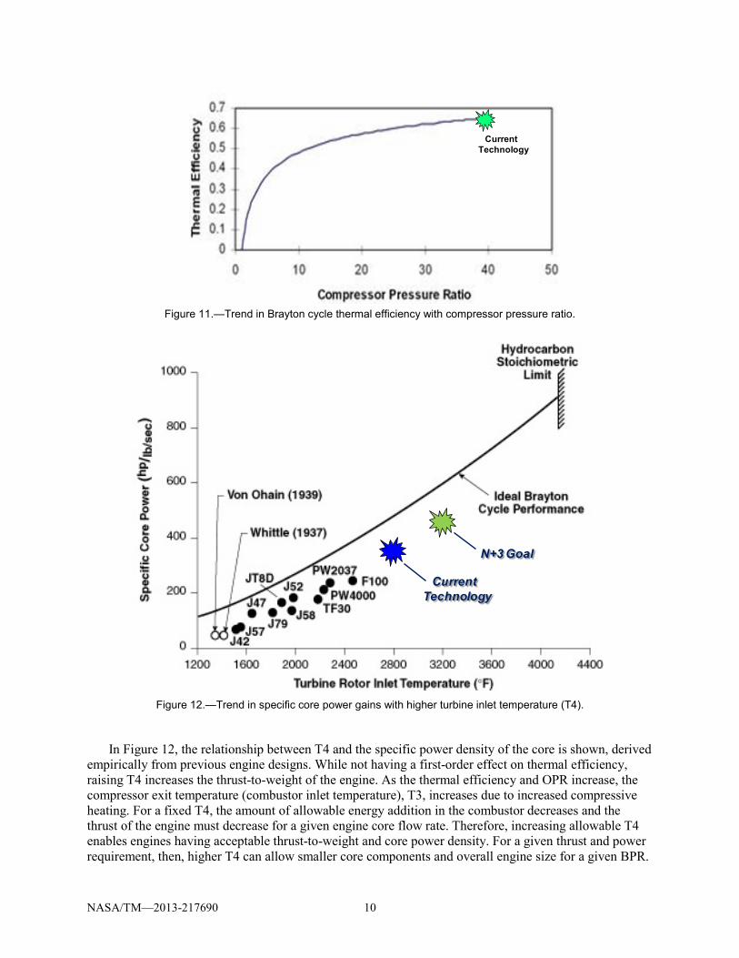
Figure 11.—Trend in Brayton cycle thermal efficiency with compressor pressure ratio.
Figure 12.—Trend in specific core power gains with higher turbine inlet temperature (T4).
In Figure 12, the relationship between T4 and the specific power density of the core is shown, derived empirically from previous engine designs. While not having a first-order effect on thermal efficiency, raising T4 increases the thrust-to-weight of the engine. As the thermal efficiency and OPR increase, the compressor exit temperature (combustor inlet temperature), T3, increases due to increased compressive heating. For a fixed T4, the amount of allowable energy addition in the combustor decreases and the thrust of the engine must decrease for a given engine core flow rate. Therefore, increasing allowable T4 enables engines having acceptable thrust-to-weight and core power density. For a given thrust and power requirement, then, higher T4 can allow smaller core components and overall engine size for a given BPR.
Current Technology
Current Technology
N+3 Goal
NASA/TM—2013-217690 11
This is important since the size of the engine increases to large diameters as BPR ratio increases (Figure 3), resulting in unacceptable high engine weight and aircraft installation challenges.
NASA and its research partners are investigating technologies to enable the high power density cores through advanced aerodynamic designs and the use of advanced, light weight and stronger materials for core components. In the aero design area (Figure 13), the emphasis of NASA research is being placed on improved design methods for high pressure, highly loaded compressors (Ref. 26) and turbines, novel turbine cooling flow techniques (Refs. 27 and 28) to improve cooling effectiveness, and novel flow control technologies for improved efficiency on compressor and turbine blades. As part of the ERA Project, NASA and its partner GE will be testing an advanced, multi stage, high speed, highly loaded compressor in the NASA Glenn W7 facility in early 2012. Detailed measurement of surface and flowfield quantities will be obtained in an effort to validate computational fluid dynamic (CFD) codes as well as to understand the physics of compressor blade row interaction and stage matching in a high speed, highly-loaded, close-coupled environment. This will be a benchmark study for the community to validate tools and improve highly-loaded compressor designs. It is expected that three-dimensional blade design methods and designs accounting for the blade row interaction effects will be incorporated into the advanced compressor design, resulting in a higher TRL through this experimental effort. NASA multi-stage turbomachinery codes will also be validated and extended through this research to account for these inter-blade row effects. These improvements will then be available to the broader gas turbine engine community for the advancement of highly-loaded turbomachinery designs and reduced fuel burn engines.
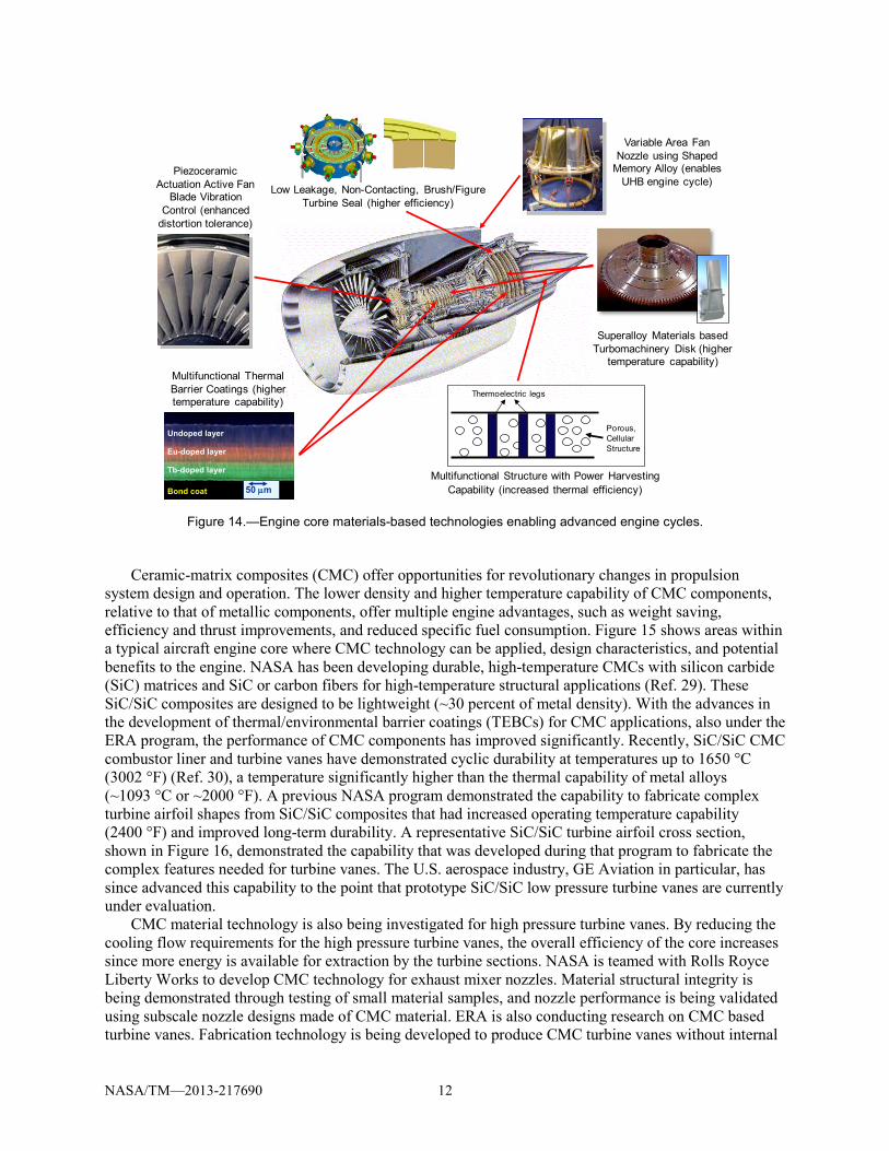
In the materials area (Figure 14), NASA and its partners are investigating methods to improve cycle efficiency by improving turbine seals; improving thermal barrier coatings on turbine blades to reduce cooling load and improve thermal efficiency; developing high strength, high temperature metal alloys to allow higher blade loadings; developing shaped memory alloys to enable varying the engine cycle for improved efficiency; and high temperature ceramic matrix composites (CMC) for turbine vane and engine nozzle components to allow for higher engine core temperatures, reduce cooling flow requirements, and lower component weight. Currently, the ERA Project is conducting research to advance the TRL of CMC components through design, fabrication and demonstration testing of larger, more complex models in a relevant environment at NASA and partner facilities.
Ceramic-matrix composites (CMC) offer opportunities for revolutionary changes in propulsion system design and operation. The lower density and higher temperature capability of CMC components, relative to that of metallic components, offer multiple engine advantages, such as weight saving, efficiency and thrust improvements, and reduced specific fuel consumption. Figure 15 shows areas within a typical aircraft engine core where CMC technology can be applied, design characteristics, and potential benefits to the engine. NASA has been developing durable, high-temperature CMCs with silicon carbide (SiC) matrices and SiC or carbon fibers for high-temperature structural applications (Ref. 29). These SiC/SiC composites are designed to be lightweight (~30 percent of metal density). With the advances in the development of thermal/environmental barrier coatings (TEBCs) for CMC applications, also under the ERA program, the performance of CMC components has improved significantly. Recently, SiC/SiC CMC combustor liner and turbine vanes have demonstrated cyclic durability at temperatures up to 1650 °C (3002 °F) (Ref. 30), a temperature significantly higher than the thermal capability of metal alloys (~1093 °C or ~2000 °F). A previous NASA program demonstrated the capability to fabricate complex turbine airfoil shapes from SiC/SiC composites that had increased operating temperature capability (2400 °F) and improved long-term durability. A representative SiC/SiC turbine airfoil cross section, shown in Figure 16, demonstrated the capability that was developed during that program to fabricate the complex features needed for turbine vanes. The U.S. aerospace industry, GE Aviation in particular, has since advanced this capability to the point that prototype SiC/SiC low pressure turbine vanes are currently under evaluation.
CMC material technology is also being investigated for high pressure turbine vanes. By reducing the cooling flow requirements for the high pressure turbine vanes, the overall efficiency of the core increases since more energy is available for extraction by the turbine sections. NASA is teamed with Rolls Royce Liberty Works to develop CMC technology for exhaust mixer nozzles. Material structural integrity is being demonstrated through testing of small material samples, and nozzle performance is being validated using subscale nozzle designs made of CMC material. ERA is also conducting research on CMC based turbine vanes. Fabrication technology is being developed to produce CMC turbine vanes without internal
Low Leakage, Non-Contacting, Brush/Figure Turbine Seal (higher efficiency)
50 µm
Undoped layer
Eu-doped layer
Tb-doped layer
Bond coat 50 µm
Undoped layer
Eu-doped layer
Tb-doped layer
Bond coat
Multifunctional Thermal Barrier Coatings (higher temperature capability)
Variable Area Fan Nozzle using Shaped
Memory Alloy (enables UHB engine cycle)
Multifunctional Structure with Power Harvesting Capability (increased thermal efficiency)
Porous,CellularStructure
Thermoelectric legs
Piezoceramic Actuation Active Fan
Blade Vibration Control (enhanced
distortion tolerance)
Superalloy Materials based Turbomachinery Disk (higher
temperature capability)
NASA/TM—2013-217690 13
material defects and with the same design features required for conventional material vane designs, including imbedded air cooling holes and thermal barrier coatings for high temperature applications.
Figure 15.—Engine component applications for CMC materials and potential benefits.
Figure 16.—Generic low pressure turbine
vane airfoil shape made with CMC SiC/SiC material.
NASA/TM—2013-217690 14
Figure 17.—Predicted reduction in Thrust Specific Fuel Consumption
with reduced cooling load with CMC High Pressure Turbine Vanes.
A recent system study (Ref. 31) on an ultra-high bypass ratio (UHB) turbofan engine for an advanced twin-engine single-aisle transport (B737/A320 class aircraft) has shown that CMC turbine vanes (assuming 3000 °F temperature capability) enable the reduction of turbine cooling and therefore increases the turbine efficiency, which enabling an average TSFC reduction of 1.5 percent for an engine with Overall Pressure Ration of 32. The TSFC benefit increases with OPR as shown in Figure 17. The study also showed that CMC materials are an enabling technology for increased bypass ratio, and thus better propulsive efficiency. Higher temperature materials allow increased turbine rotor inlet temperature, which increases specific power of the engine, allowing a higher bypass ratio. Also, as Tbulk is allowed to increase, less turbine chargeable cooling is required. Core size shrinks as the demand of cooling air decreases.
Summary The NASA Aeronautics Research Mission Directorate has established two Projects to investigate,
develop, and demonstrate in partnership with U.S. Industry, Academia, and other Government Agencies, advanced subsonic transport aircraft technology to significantly reduce the impact of aircraft on the environment. The Subsonic Fixed Wing Project, under the Fundamental Aeronautics Program, established in 2006, is tasked to support fundamental research to Technology Readiness Level of 1 to 3 for application to aircraft designs beyond 2025, or N+3 generation of aircraft. The Environmentally Responsible Aviation Project, under the Integrated Systems Research Program, is tasked to further develop the aircraft technology showing potential for meeting the system environmental goals to a Technology Readiness Level of 4 to 6 by 2020, or N+2 generation aircraft.
NASA and its partners under the SFW and ERA Projects to date have demonstrated significant progress toward meeting the NASA Subsonic Transport System Level Metrics for installed fuel burn reduction with: advanced engine technology research in the areas of Ultra High Bypass and Open Rotor engine cycles to increase propulsive efficiency; advanced engine core research to produce higher propulsive and thermal efficiencies with higher Overall Pressure Ratio and Turbine Inlet Temperatures; advanced, three dimensional aerodynamic compressor and turbine designs; and advanced materials research in Ceramic Metal Composites and Superalloys to allow higher blade loading per stage to reduce engine weight as well as reduce turbine cooling requirements to increase overall efficiency. Project research includes computational design and analysis, including code validation; subscale model testing to verify technologies in laboratory and in relevant, complex, operational environments; and finally system level demonstrations of full scale components.
NASA/TM—2013-217690 15
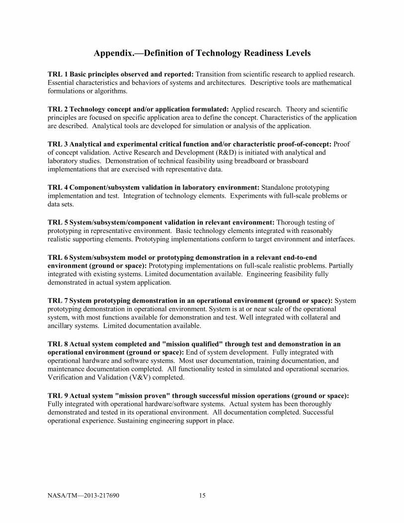
Appendix.—Definition of Technology Readiness Levels TRL 1 Basic principles observed and reported: Transition from scientific research to applied research. Essential characteristics and behaviors of systems and architectures. Descriptive tools are mathematical formulations or algorithms. TRL 2 Technology concept and/or application formulated: Applied research. Theory and scientific principles are focused on specific application area to define the concept. Characteristics of the application are described. Analytical tools are developed for simulation or analysis of the application. TRL 3 Analytical and experimental critical function and/or characteristic proof-of-concept: Proof of concept validation. Active Research and Development (R&D) is initiated with analytical and laboratory studies. Demonstration of technical feasibility using breadboard or brassboard implementations that are exercised with representative data. TRL 4 Component/subsystem validation in laboratory environment: Standalone prototyping implementation and test. Integration of technology elements. Experiments with full-scale problems or data sets. TRL 5 System/subsystem/component validation in relevant environment: Thorough testing of prototyping in representative environment. Basic technology elements integrated with reasonably realistic supporting elements. Prototyping implementations conform to target environment and interfaces. TRL 6 System/subsystem model or prototyping demonstration in a relevant end-to-end environment (ground or space): Prototyping implementations on full-scale realistic problems. Partially integrated with existing systems. Limited documentation available. Engineering feasibility fully demonstrated in actual system application. TRL 7 System prototyping demonstration in an operational environment (ground or space): System prototyping demonstration in operational environment. System is at or near scale of the operational system, with most functions available for demonstration and test. Well integrated with collateral and ancillary systems. Limited documentation available. TRL 8 Actual system completed and "mission qualified" through test and demonstration in an operational environment (ground or space): End of system development. Fully integrated with operational hardware and software systems. Most user documentation, training documentation, and maintenance documentation completed. All functionality tested in simulated and operational scenarios. Verification and Validation (V&V) completed. TRL 9 Actual system "mission proven" through successful mission operations (ground or space): Fully integrated with operational hardware/software systems. Actual system has been thoroughly demonstrated and tested in its operational environment. All documentation completed. Successful operational experience. Sustaining engineering support in place.
NASA/TM—2013-217690 16
References 1. National Aeronautics Research and Development Policy and Plan,
http://www.ostp.gov/cs/nstc/documents_reports 2. Madavan, Nateri, “NASA Subsonic Fixed Wing (SFW) Project Research Overview,” presentation at
the ASME Turbo Expo 2011, Jun 2011. 3. Hughes, Christopher E., “An Overview of the NASA Fundamental Aeronautics Program Subsonic
Fixed Wing Project and Ultra High Bypass Partnership Research Goals,” presentation at the 15th AIAA/CEAS Aeroacoustics Conference (30th AIAA Aeroacoustics Conference), May 2009.
4. Collier, Fayette; “Environmentally Responsible Aviation - Real solutions for environmental challenges facing aviation,” Report NF1676L-11223 (URL: http://ntrs.nasa.gov), GARDN, First Green Aviation Conference, Feb 2011.
5. Berton, J., and Guynn, M.: “Multi-Objective Optimization of Turbofan Design Parameters for an Advanced, Single-Aisle Transport,” AIAA Paper 2010-9168, AIAA 10th Aviation Technology, Integration, and Operations (ATIO) Conference, Sep 2010.
6. Guynn, M.; Berton, J.; Fisher, K.; Haller, W.; Tong, M.; and Thurman, D.: “Refined Exploration of Turbofan Design Options for an Advanced Single-Aisle Transport Aircraft,” NASA/TM—2011-216883, Jan2011.
7. Tong, Michael T.; Jones, Scott M.; Haller, William J,; Handschuh, Robert F.; “Engine Conceptual Design Studies for a Hybrid Wing Body Aircraft,” NASA/TM—2009-215680, Nov 2009.
8. Hughes, Christopher, NASA Glenn Research Center; Schweitzer, Jeff, Pratt & Whitney; “Ultra High Bypass Ratio Engine Research for Reducing Noise, Emissions, and Fuel Consumption,” Document 20080005581 (URL: http://ntrs.nasa.gov), NASA Fundamental Aeronautics Program 1st Annual Review, Oct 2007.
9. Hughes, Christopher E., “Collaborative Research on the Ultra High Bypass Ratio Engine Cycle to Reduce Noise, Emissions and Fuel Consumption,” Report E-16711 (URL: http://ntrs.nasa.gov), UTIAS-MITACS International Workshop on Aviation and Climate Change, May 2008.
10. Hughes, Christopher E., “NASA Partnerships and Collaborative Research on Ultra High Bypass Cycle Propulsion Concepts,” Report E-16904 (URL: http://ntrs.nasa.gov), Acoustics Technical Working Group Meeting, Sept 2008.
11. Hughes, Christopher E., “NASA Collaborative Research on the Ultra High Bypass Engine Cycle and Potential Benefits for Noise, Performance and Emissions,” ISABE-2009-1274, 2009.
12. Hughes, Christopher E., NASA Glenn Research Center; Lord, Wesley, Pratt & Whitney; “NASA/Pratt & Whitney Collaborative Partnership Research in Ultra High Bypass Cycle Propulsion Concepts,” Report E-16905 (URL: http://ntrs.nasa.gov), Fundamental Aeronautics Program 2nd Annual Review, Oct 2008.
13. Hughes, Christopher, “Geared Turbofan Technology,” presentation at the NASA Green Aviation Summit, September 2010, URL: www.aeronautics.nasa.gov/pdf/hughes_green_aviation_summit.pdf.
14. Hughes, Christopher, and Smith, Steven; “The Promise and Challenges of Ultra High Bypass Ratio Engine Technology and Integration,” Report HQ-STI-11-012 (URL: http://ntrs.nasa.gov), AIAA 49th Aerospace Sciences Meeting, Jan 2011.
15. Hughes, C., and Edmane, E., “Overview of Recent Ultra High Bypass Engine Cycle-Based Scale Model Test Results,” presentation at the Fundamental Aeronautics Program 3rd Annual Review, Sep 2009.
16. Hughes, Christopher, NASA Glenn Research Center; Zeug, Theresa, GE Aviation; “NASA/GE Aviation Collaborative Partnership Research in Ultra High Bypass Cycle Propulsion Concepts,” Report E-16903 (URL: http://ntrs.nasa.gov), Fundamental Aeronautics Program 2nd Annual Review, Oct 2008.
17. Van Zante, Dale, and Breeze-Stringfellow, Andrew, “The NASA/GE Collaboration on Open Rotor Testing,” presentation at the University of Toronto Institute for Aerospace Studies: Workshop on Aviation and Climate Change, May 2010.
18. Van Zante, Dale, and Breeze-Stringfellow, Andy, “The NASA/GE Collaboration on Open Rotor Testing,” presentation at the Royal Aeronautical Society, Conference on Applied Aerodynamics: Capabilities and Future Requirements, Jul 2010.
19. Hendricks, Eric, “Development of an Open Rotor Cycle Model in NPSS using s Multi-Design Point Approach,” GT2011-46694, ASME Turbo Expo 2011, Jun 2011.
20. Van Zante, Dale E., “NASA/GE Collaboration on Open Rotors - High Speed Testing,” Report E-17798 (URL: http://ntrs.nasa.gov), Acoustics Technical Working Group, NASA Glenn Research Center, May 2011.
21. Van Zante, Dale, “Reestablishing Open Rotor as an Option for Significant Fuel Burn Improvements,” Report HQ-STI-11-013 (URL: http://ntrs.nasa.gov), AIAA 49th Aero Sciences Meeting, Jan 2011.
22. Van Zante, Dale; Wojno, John; “The NASA/GE Open Rotor Research Campaign: ERA Diagnostics Test,” presentation at the ASME Turbo Expo 2011, Jun 2011.
23. Van Zante, Dale; Gazzaniga, John; Elliott, David; and Woodward, Richard; “An Open Rotor Test Case: F31/A31 Historical Baseline Blade Set,” ISABE-2011-1310, Sep 2011.
24. Hiedmann, James, “Advanced Core Engine Technology,” presentation at the NASA Green Aviation Summit, Sep 2010, URL: www.aeronautics.nasa.gov/pdf/hughes_green_aviation_summit.pdf.
25. Heidmann, James; “Improving Engine Efficiency through Core Developments,” presentation at the AIAA 49th Aero Sciences Meeting, Jan 2011.
26. Lurie, E. A., Van Slooten, P.R., Medic, G., Mulugeta, J.M., Holley, B. M., Feng, J., Sharma, O., and Ni, R., “Design of a High Efficiency Compact Centrifugal Compressor for Rotorcraft Applications,” Proceedings of AHS Forum 67, May 2011.
27. Heidmann, J., and Ekkad, S.V., A Novel Anti-Vortex Turbine Film Cooling Hole Concept, ASME Journal of Turbomachinery, Jul 2008, Vol. 130.
28. Dhungel, A., Lu, Y., Phillips, W.A., Ekkad, S.V., Heidmann, J., Film Cooling from a Row of Holes Supplemented with Anti-vortex Holes, ASME Journal of Turbomachinery, Jan 2009, Vol. 131.
29. DiCarlo, J. A., et al, “High-Performance SiC/SiC Ceramic Composite Systems Developed for 1315 °C (2400 °F) Engine Components,” NASA/TM—2004-212729, 2004, pp.12-13.
30. Zhu, D., Miller, R. A., Fox, D. S., “Thermal and Environmental Barrier Coating Development for Advanced Propulsion Engine Systems,” NASA/TM—2008-215040.
31. Tong, M. T., “An Assessment of the Impact of Emerging High-Temperature Materials on Engine Cycle Performance,” GT2010-22361, ASME Turbo Expo 2010, Jun 2010.
REPORT DOCUMENTATION PAGE Form Approved OMB No. 0704-0188
The public reporting burden for this collection of information is estimated to average 1 hour per response, including the time for reviewing instructions, searching existing data sources, gathering and maintaining the data needed, and completing and reviewing the collection of information. Send comments regarding this burden estimate or any other aspect of this collection of information, including suggestions for reducing this burden, to Department of Defense, Washington Headquarters Services, Directorate for Information Operations and Reports (0704-0188), 1215 Jefferson Davis Highway, Suite 1204, Arlington, VA 22202-4302. Respondents should be aware that notwithstanding any other provision of law, no person shall be subject to any penalty for failing to comply with a collection of information if it does not display a currently valid OMB control number. PLEASE DO NOT RETURN YOUR FORM TO THE ABOVE ADDRESS.
1. REPORT DATE (DD-MM-YYYY) 01-11-2013
2. REPORT TYPE Technical Memorandum
3. DATES COVERED (From - To)
4. TITLE AND SUBTITLE Aircraft Engine Technology for Green Aviation to Reduce Fuel Burn
5a. CONTRACT NUMBER
5b. GRANT NUMBER
5c. PROGRAM ELEMENT NUMBER
6. AUTHOR(S) Hughes, Christopher, E.; Van Zante, Dale, E.; Heidmann, James, D.
5d. PROJECT NUMBER
5e. TASK NUMBER
5f. WORK UNIT NUMBER WBS 699959.02.09.03.06
7. PERFORMING ORGANIZATION NAME(S) AND ADDRESS(ES) National Aeronautics and Space Administration John H. Glenn Research Center at Lewis Field Cleveland, Ohio 44135-3191
8. PERFORMING ORGANIZATION REPORT NUMBER E-18373
9. SPONSORING/MONITORING AGENCY NAME(S) AND ADDRESS(ES) National Aeronautics and Space Administration Washington, DC 20546-0001
10. SPONSORING/MONITOR'S ACRONYM(S) NASA
11. SPONSORING/MONITORING REPORT NUMBER NASA/TM-2013-217690
12. DISTRIBUTION/AVAILABILITY STATEMENT Unclassified-Unlimited Subject Category: 07 Available electronically at http://www.sti.nasa.gov This publication is available from the NASA Center for AeroSpace Information, 443-757-5802
13. SUPPLEMENTARY NOTES
14. ABSTRACT The NASA Fundamental Aeronautics Program Subsonic Fixed Wing Project and Integrated Systems Research Program Environmentally Responsible Aviation Project in the Aeronautics Research Mission Directorate are conducting research on advanced aircraft technology to address the environmental goals of reducing fuel burn, noise and NOx emissions for aircraft in 2020 and beyond. Both Projects, in collaborative partnerships with U.S. Industry, Academia, and other Government Agencies, have made significant progress toward reaching the N+2 (2020) and N+3 (beyond 2025) installed fuel burn goals by fundamental aircraft engine technology development, subscale component experimental investigations, full scale integrated systems validation testing, and development validation of state of the art computation design and analysis codes. Specific areas of propulsion technology research are discussed and progress to date.15. SUBJECT TERMS Ultra high bypass; ERA; Wind tunnel
16. SECURITY CLASSIFICATION OF: 17. LIMITATION OF ABSTRACT UU
18. NUMBER OF PAGES
24
19a. NAME OF RESPONSIBLE PERSON STI Help Desk (email:[email protected])
a. REPORT U
b. ABSTRACT U
c. THIS PAGE U
19b. TELEPHONE NUMBER (include area code) 443-757-5802
Standard Form 298 (Rev. 8-98)Prescribed by ANSI Std. Z39-18