Aircraft Manufacturing Facility Design By: Dan Wiegandt, Manager of Engineering, and Ken Stone, Vice President and Project Executive Mies van dehr Rohr said, “God is in the details,” and for aircraft manufacturing facilities, there are a lot of details. Aerospace and aviation facilities have been a core component of The Austin Company’s business since 1917. From the days of Curtiss Wright, to current commercial and military aircraft manufacturing facilities, Austin has been helping aerospace clients meet the demands of their manufacturing requirements by providing cost-effective, high-quality facilities on very short schedules. While far from comprehensive, this whitepaper provides an overview of several high-level considerations that must be addressed in the design and construction of manufacturing facilities for aircraft and associated components. Austin’s nearly 100 years of experience in planning, designing, engineering and constructing these types of facilities keeps us well-versed in the many unique features associated with these specialized buildings. MANUFACTURING AND ASSEMBLY BUILDINGS Everything about an aircraft manufacturing and assembly building must be driven by the manufacturing process, including process flow, process rate and process requirements. The building must fully support the process, in addition to “keeping the weather out.” The manufacturing process must be well understood at a macro level by the facility planning and engineering team to ensure that an appropriate building concept is developed that is integrated with manufacturing needs. In addition, individual manufacturing areas within the building must be understood on a finite level to ensure that the facility and infrastructure supports manufacturing efficiently. Following are key considerations related to an Assembly Building that must be evaluated during planning to establish an appropriate building overall design: Manufacturing Process Type and Style The manufacturing process type and style may include: flow line, fixed position assembly, parallel assembly, subassembly shops and fishbone assembly, all of which will determine the building’s size and layout. Different manufacturing process flows will likely be used for different components or steps within the overall process. Page 1
Transcript
Aircraft Manufacturing Facility Design
By: Dan Wiegandt, Manager of Engineering, and Ken Stone, Vice President and Project Executive
Mies van dehr Rohr said, “God is in the details,” and for aircraft manufacturing facilities, there are a lot of details.
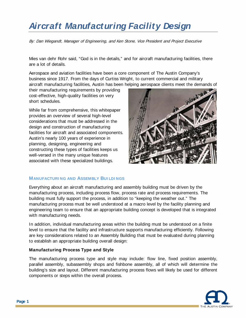
Aerospace and aviation facilities have been a core component of The Austin Company’s business since 1917. From the days of Curtiss Wright, to current commercial and military aircraft manufacturing facilities, Austin has been helping aerospace clients meet the demands of their manufacturing requirements by providing cost-effective, high-quality facilities on very short schedules.
While far from comprehensive, this whitepaper provides an overview of several high-level considerations that must be addressed in the design and construction of manufacturing facilities for aircraft and associated components. Austin’s nearly 100 years of experience in planning, designing, engineering and constructing these types of facilities keeps us well-versed in the many unique features associated with these specialized buildings.
MANUFACTURING AND ASSEMBLY BUILDINGS
Everything about an aircraft manufacturing and assembly building must be driven by the manufacturing process, including process flow, process rate and process requirements. The building must fully support the process, in addition to “keeping the weather out.” The manufacturing process must be well understood at a macro level by the facility planning and engineering team to ensure that an appropriate building concept is developed that is integrated with manufacturing needs.
In addition, individual manufacturing areas within the building must be understood on a finite level to ensure that the facility and infrastructure supports manufacturing efficiently. Following are key considerations related to an Assembly Building that must be evaluated during planning to establish an appropriate building overall design:
Manufacturing Process Type and Style
The manufacturing process type and style may include: flow line, fixed position assembly, parallel assembly, subassembly shops and fishbone assembly, all of which will determine the building’s size and layout. Different manufacturing process flows will likely be used for different components or steps within the overall process.
Page 1
Aircraft Manufacturing Facility Design
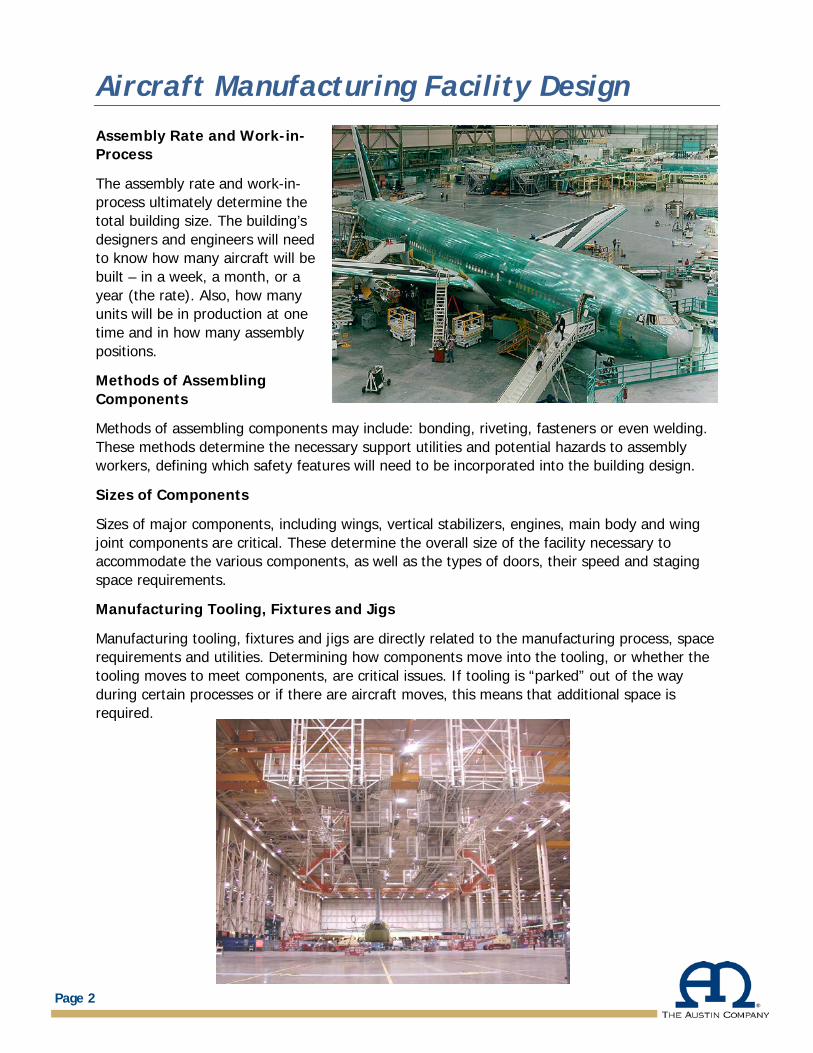
Assembly Rate and Work-in-Process
The assembly rate and work-in-process ultimately determine the total building size. The building’s designers and engineers will need to know how many aircraft will be built – in a week, a month, or a year (the rate). Also, how many units will be in production at one time and in how many assembly positions.
Methods of Assembling Components
Methods of assembling components may include: bonding, riveting, fasteners or even welding. These methods determine the necessary support utilities and potential hazards to assembly workers, defining which safety features will need to be incorporated into the building design.
Sizes of Components
Sizes of major components, including wings, vertical stabilizers, engines, main body and wing joint components are critical. These determine the overall size of the facility necessary to accommodate the various components, as well as the types of doors, their speed and staging space requirements.
Manufacturing Tooling, Fixtures and Jigs
Manufacturing tooling, fixtures and jigs are directly related to the manufacturing process, space requirements and utilities. Determining how components move into the tooling, or whether the tooling moves to meet components, are critical issues. If tooling is “parked” out of the way during certain processes or if there are aircraft moves, this means that additional space is required.
Page 2
Aircraft Manufacturing Facility Design
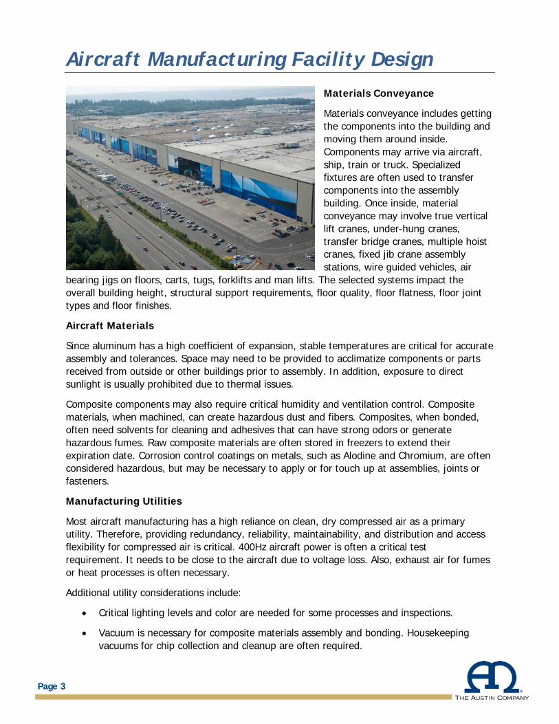
Materials Conveyance
Materials conveyance includes getting the components into the building and moving them around inside. Components may arrive via aircraft, ship, train or truck. Specialized fixtures are often used to transfer components into the assembly building. Once inside, material conveyance may involve true vertical lift cranes, under-hung cranes, transfer bridge cranes, multiple hoist cranes, fixed jib crane assembly stations, wire guided vehicles, air
bearing jigs on floors, carts, tugs, forklifts and man lifts. The selected systems impact the overall building height, structural support requirements, floor quality, floor flatness, floor joint types and floor finishes.
Aircraft Materials
Since aluminum has a high coefficient of expansion, stable temperatures are critical for accurate assembly and tolerances. Space may need to be provided to acclimatize components or parts received from outside or other buildings prior to assembly. In addition, exposure to direct sunlight is usually prohibited due to thermal issues.
Composite components may also require critical humidity and ventilation control. Composite materials, when machined, can create hazardous dust and fibers. Composites, when bonded, often need solvents for cleaning and adhesives that can have strong odors or generate hazardous fumes. Raw composite materials are often stored in freezers to extend their expiration date. Corrosion control coatings on metals, such as Alodine and Chromium, are often considered hazardous, but may be necessary to apply or for touch up at assemblies, joints or fasteners.
Manufacturing Utilities
Most aircraft manufacturing has a high reliance on clean, dry compressed air as a primary utility. Therefore, providing redundancy, reliability, maintainability, and distribution and access flexibility for compressed air is critical. 400Hz aircraft power is often a critical test requirement. It needs to be close to the aircraft due to voltage loss. Also, exhaust air for fumes or heat processes is often necessary.
Additional utility considerations include:
• Critical lighting levels and color are needed for some processes and inspections.
• Vacuum is necessary for composite materials assembly and bonding. Housekeeping vacuums for chip collection and cleanup are often required.
Page 3
Aircraft Manufacturing Facility Design
• Fuel test agents are often piped to critical testing locations during component or
assembly testing. Keep in mind, fuel test agents are combustible oils with special requirements, as well. Code officials and insurance underwriters need to understand the fire-related issues with these materials.
• Hydraulic systems provide aircraft power to function flaps, wings, doors and landing gear. Hydraulic systems need to be filled, drained and may operate at high pressures. Care must be taken for personnel safety, avoiding leaks or spills and to ensure over-pressurization or damage does not occur to the aircraft.
• High volume, low pressure compressed air is used for pneumatic testing, such as fuselage pressure testing.
• Aircraft grounding is important. Static electricity can damage sensitive electronic components.
• In an automated assembly factory, data communication is often necessary everywhere on the shop floor, including at the aircraft and all jigs and fixtures. High speed and wireless networks enable critical data to be available or sent directly from the shop floor.
Page 4
Aircraft Manufacturing Facility Design
Utility Distribution
Getting each of the required utilities to the right assembly location in a flexible and adaptable method can be a challenge. The option of overhead utilities distribution is impacted by cranes, while in-floor trenches can impact rolling material handling systems or prevent air bearings from working effectively. Recessed in-floor boxes are an option, but impact flexibility for future factory modifications. In-floor retractable pedestals are expensive, but proving to be a functional alternative. Electrical cords, air hoses, pipes and conduit running across the floor are safety issues, but are often necessary. Each individual manufacturing position may need a different distribution method based on its specific manufacturing or workflow requirements.
Foreign Object Debris (FOD)
No building materials, condensation, water, manufacturing waste, fasteners or other objects can fall on or into the aircraft during assembly. All potential sources of FOD must be well thought out and mitigated. Broken light bulbs, fireproofing fibers, paint chips and other building-related foreign debris need to be prevented from entering the manufacturing process.
Exiting
Aircraft manufacturing facilities are often large buildings. Exit distances can often exceed code requirements. Exit egress from jigs or tooling platforms and around aircraft and materials must be well thought out. When exit distances become a problem, exit tunnels under the manufacturing floor can be used to create an exit path or an area of refuge. Emergency lighting is also a challenge in these large facilities. Designated marked exit paths are usually used.
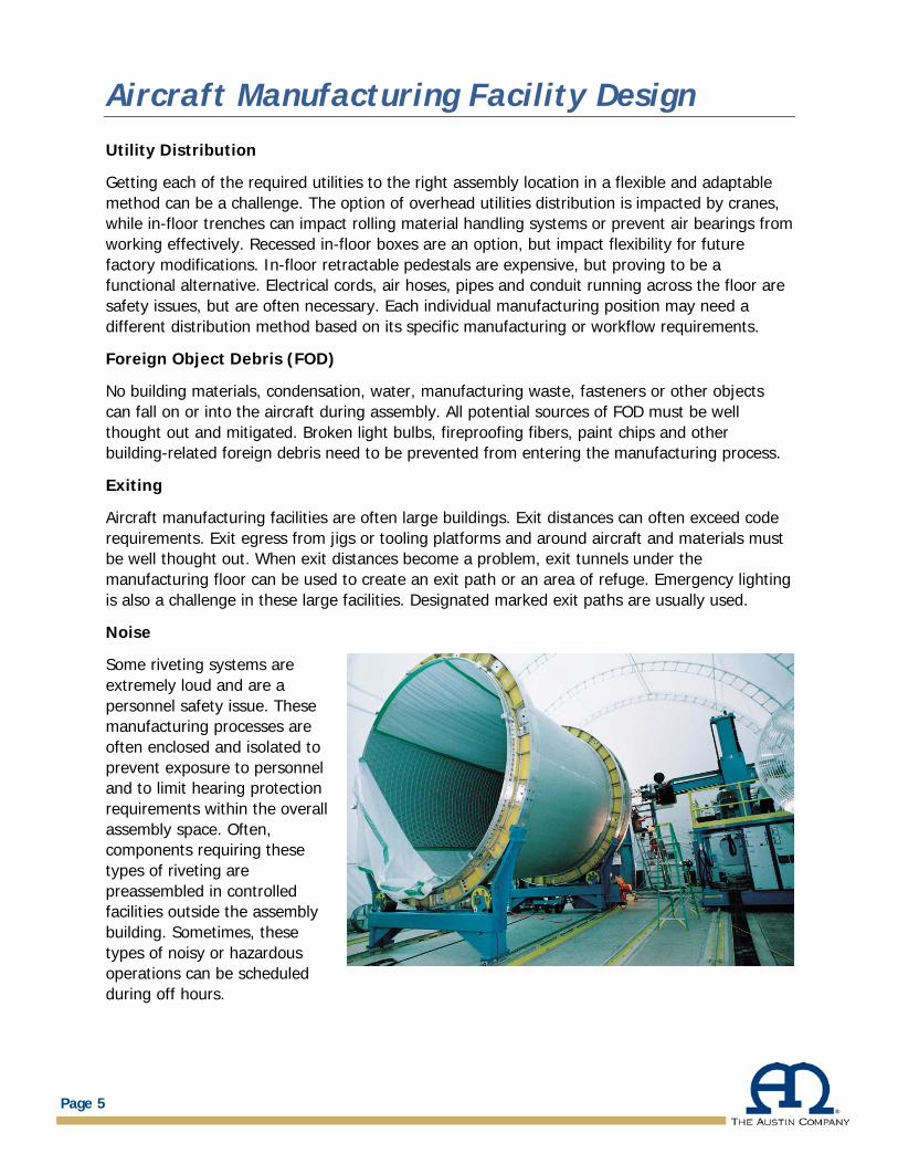
Noise
Some riveting systems are extremely loud and are a personnel safety issue. These manufacturing processes are often enclosed and isolated to prevent exposure to personnel and to limit hearing protection requirements within the overall assembly space. Often, components requiring these types of riveting are preassembled in controlled facilities outside the assembly building. Sometimes, these types of noisy or hazardous operations can be scheduled during off hours.
Page 5
Aircraft Manufacturing Facility Design
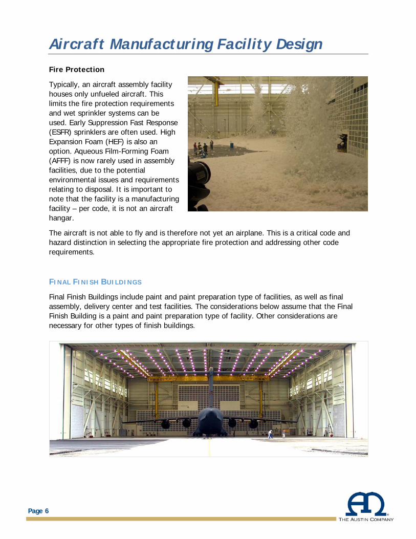
Fire Protection
Typically, an aircraft assembly facility houses only unfueled aircraft. This limits the fire protection requirements and wet sprinkler systems can be used. Early Suppression Fast Response (ESFR) sprinklers are often used. High Expansion Foam (HEF) is also an option. Aqueous Film-Forming Foam (AFFF) is now rarely used in assembly facilities, due to the potential environmental issues and requirements relating to disposal. It is important to note that the facility is a manufacturing facility – per code, it is not an aircraft hangar.
The aircraft is not able to fly and is therefore not yet an airplane. This is a critical code and hazard distinction in selecting the appropriate fire protection and addressing other code requirements.
FINAL FINISH BUILDINGS
Final Finish Buildings include paint and paint preparation type of facilities, as well as final assembly, delivery center and test facilities. The considerations below assume that the Final Finish Building is a paint and paint preparation type of facility. Other considerations are necessary for other types of finish buildings.
Page 6
Aircraft Manufacturing Facility Design
Manufacturing Process within the aircraft manufacturing Final Finish Building:
Final Finish Building manufacturing processes are usually used for aircraft surface preparation, masking, painting, curing/drying of the finish and then additional painting, striping or decal application and clean up. The building is often shaped by specialized environmental requirements, based on the requirements of the coatings or finishes that are applied, removed or cured. Many of these coatings or finishes are hazardous or flammable, so considerations relating to personnel exposure and safety are critical. These buildings have very large air conditioning, heating, humidity control and airflow requirements. Considerable manufacturing process equipment is required.
Finish Rate
Typically, it takes twice as long to prepare an aircraft for paint as it does to paint it. From a process flow and planning standpoint, this is an important consideration. Two preparation bays may be required for a single paint bay, depending on the given production rate. If a single bay is used for preparation and finish paint, then additional time is required to clean the aircraft and the facility after preparation and before paint application to eliminate any particulate, fibers, dust or debris, which would adversely impact the finish. The manufacturing time for each step in the process needs to be carefully evaluated.
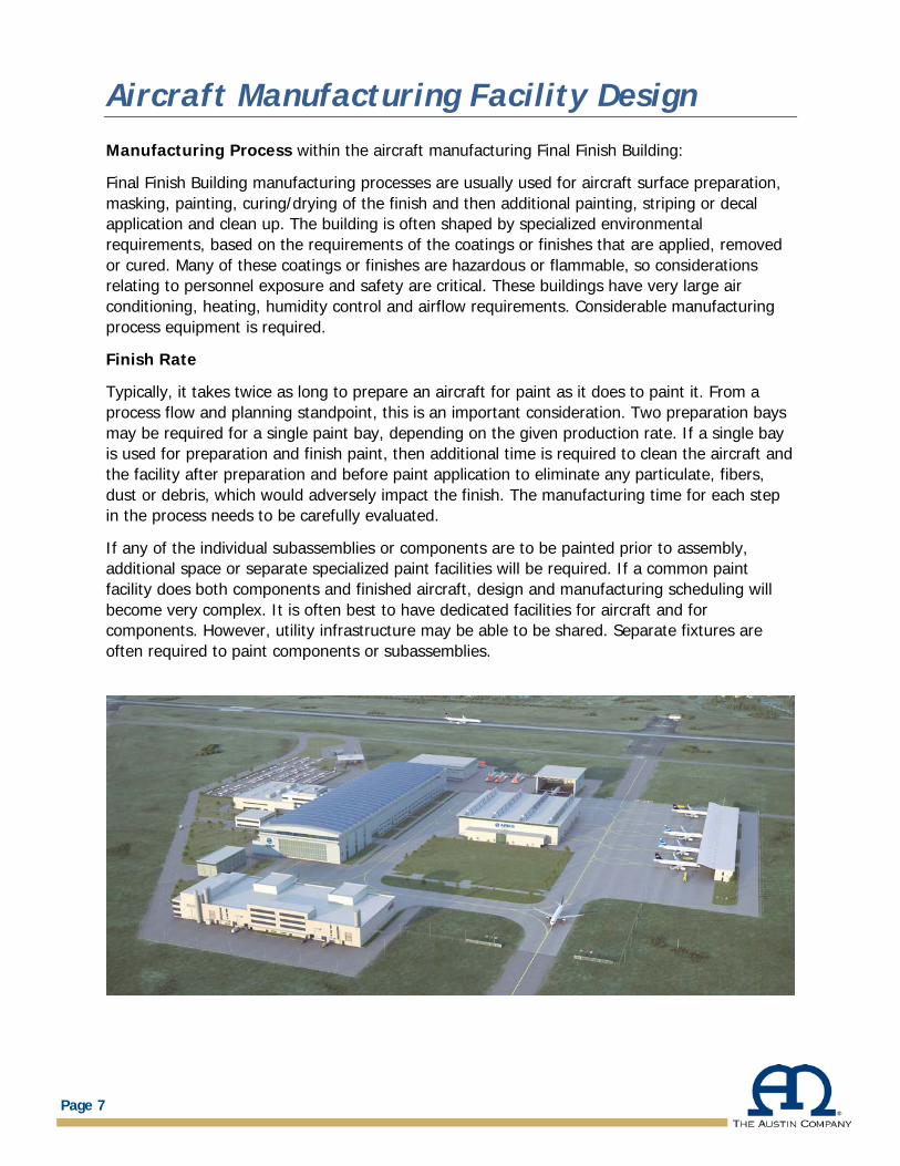
If any of the individual subassemblies or components are to be painted prior to assembly, additional space or separate specialized paint facilities will be required. If a common paint facility does both components and finished aircraft, design and manufacturing scheduling will become very complex. It is often best to have dedicated facilities for aircraft and for components. However, utility infrastructure may be able to be shared. Separate fixtures are often required to paint components or subassemblies.
Page 7
Aircraft Manufacturing Facility Design
Environmental Conditions
Ideally, finish paint applications need to take place in a clean, dust-free and climate-controlled environment. Depending on finish materials, humidity and temperature control is critical. This is made more difficult due to the high volume of air required to maintain a safe paint environment for workers. Airflow across the painted surfaces is often in the 50-150 feet per minute range, depending on the finish coating and application technique. This air is usually exhausted due to it containing paint particulate, solvents and hazardous vapors. The exhaust will likely need to be treated to limit particulate, solvents, odors or other environmental concerns from being exhausted. In addition, volatile organic compounds may need to be captured or treated. This will result in large supply air and exhaust systems with very notable energy consumption.
In some situations, exhaust air can be recycled after treatment to save on the overall air volume that requires temperature or humidity treatment.
Many aerospace coatings require elevated cure temperatures. In these situations, a facility hot box may need to be created with significant airflow to properly or rapidly cure the coating after the paint is applied. Robotic painting systems are a consideration – often requiring less airflow due to the elimination of personnel from the paint application environment.
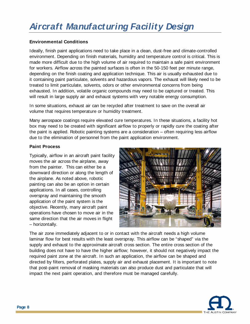
Paint Process
Typically, airflow in an aircraft paint facility moves the air across the airplane, away from the painter. This can either be a downward direction or along the length of the airplane. As noted above, robotic painting can also be an option in certain applications. In all cases, controlling overspray and maintaining the smooth application of the paint system is the objective. Recently, many aircraft paint operations have chosen to move air in the same direction that the air moves in flight – horizontally.
The air zone immediately adjacent to or in contact with the aircraft needs a high volume laminar flow for best results with the least overspray. This airflow can be “shaped” via the supply and exhaust to the approximate aircraft cross section. The entire cross section of the building does not have to have the higher airflow; however, it should not negatively impact the required paint zone at the aircraft. In such an application, the airflow can be shaped and directed by filters, perforated plates, supply air and exhaust placement. It is important to note that post-paint removal of masking materials can also produce dust and particulate that will impact the next paint operation, and therefore must be managed carefully.
Page 8
Aircraft Manufacturing Facility Design
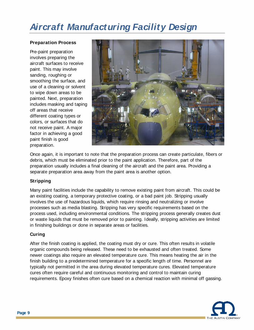
Preparation Process
Pre-paint preparation involves preparing the aircraft surfaces to receive paint. This may involve sanding, roughing or smoothing the surface, and use of a cleaning or solvent to wipe down areas to be painted. Next, preparation includes masking and taping off areas that receive different coating types or colors, or surfaces that do not receive paint. A major factor in achieving a good paint finish is good preparation.
Once again, it is important to note that the preparation process can create particulate, fibers or debris, which must be eliminated prior to the paint application. Therefore, part of the preparation usually includes a final cleaning of the aircraft and the paint area. Providing a separate preparation area away from the paint area is another option.
Stripping
Many paint facilities include the capability to remove existing paint from aircraft. This could be an existing coating, a temporary protective coating, or a bad paint job. Stripping usually involves the use of hazardous liquids, which require rinsing and neutralizing or involve processes such as media blasting. Stripping has very specific requirements based on the process used, including environmental conditions. The stripping process generally creates dust or waste liquids that must be removed prior to painting. Ideally, stripping activities are limited in finishing buildings or done in separate areas or facilities.
Curing
After the finish coating is applied, the coating must dry or cure. This often results in volatile organic compounds being released. These need to be exhausted and often treated. Some newer coatings also require an elevated temperature cure. This means heating the air in the finish building to a predetermined temperature for a specific length of time. Personnel are typically not permitted in the area during elevated temperature cures. Elevated temperature cures often require careful and continuous monitoring and control to maintain curing requirements. Epoxy finishes often cure based on a chemical reaction with minimal off gassing.
Page 9
Aircraft Manufacturing Facility Design
Paint Equipment
Paint equipment will vary depending on the finish coating. Airless, electrostatic, high volume low pressure (HVLP), pressurized pot and two-part mixing sprayers are all options. Each of these spray technologies have different characteristics and utility requirements that must be taken into consideration. Frequently, more than one system will be used on an aircraft due to different areas, colors or finish requirements.
Personnel Access to the Aircraft
To clean, prepare and paint the aircraft, personnel must be close enough to physically and safely touch every single surface and part of the aircraft. This can be accomplished with automated crane mounted platforms, fixtures, ladders, rolling or fixed platforms, or other methods that provide access without physically touching or making contact with the aircraft. Such equipment must provide safe access to all aircraft surfaces, without creating unwanted air disturbances during painting. Fall protection and freedom of movement for the painters are critical issues to be addressed.
Fire Protection
If an elevated temperature cure is required, sprinkler selection must be very carefully reviewed. Since it is a paint facility, sprinkler heads must be protected from paint overspray – paint overspray will insulate the sprinkler head, rendering it useless.
Recessed heads are an option. Often, sprinkler heads are protected with a combustible plastic bag that will melt at a given temperature. Typically, the aircraft is unfueled, so foam-based fire protection systems are not required.
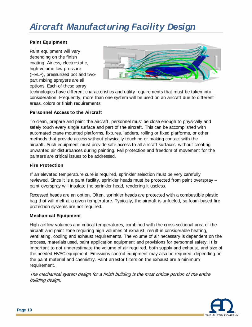
Mechanical Equipment
High airflow volumes and critical temperatures, combined with the cross-sectional area of the aircraft and paint zone requiring high volumes of exhaust, result in considerable heating, ventilating, cooling and exhaust requirements. The volume of air necessary is dependent on the process, materials used, paint application equipment and provisions for personnel safety. It is important to not underestimate the volume of air required, both supply and exhaust, and size of the needed HVAC equipment. Emissions-control equipment may also be required, depending on the paint material and chemistry. Paint arrestor filters on the exhaust are a minimum requirement.
The mechanical system design for a finish building is the most critical portion of the entire building design.
Page 10
Aircraft Manufacturing Facility Design
Computational fluid dynamics software is typically used to model the airflow. Consideration for maintenance of these mechanical systems is also very important. Systems operation is critical to the performance of the finish facility. Reliability, maintainability and redundancy are all considerations for the mechanical equipment.
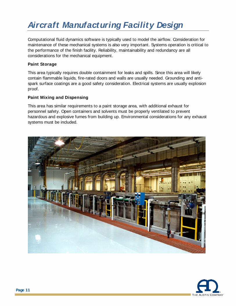
Paint Storage
This area typically requires double containment for leaks and spills. Since this area will likely contain flammable liquids, fire-rated doors and walls are usually needed. Grounding and anti-spark surface coatings are a good safety consideration. Electrical systems are usually explosion proof.
Paint Mixing and Dispensing
This area has similar requirements to a paint storage area, with additional exhaust for personnel safety. Open containers and solvents must be properly ventilated to prevent hazardous and explosive fumes from building up. Environmental considerations for any exhaust systems must be included.
Page 11
Aircraft Manufacturing Facility Design
TEST CELLS AND HUSH HOUSES
In the United States, Test Cells and Hush Houses are typically highly-specialized pieces of equipment manufactured by a vendor that specializes in this equipment. Most Test Cells and Hush Houses are essentially “equipment” that an aircraft is backed up to, so an engine run up test can be performed. The noise and heat produced by the jet engine is directed into an augmenter tube horizontally and then is usually redirected vertically. Such a facility will include sound suppression capabilities to reduce the engine noise. Cooling is typically provided by inducing outside air.
If the engine is mounted on the aircraft, the Hush House is a standalone structure to which the aircraft connects. If the engine is not installed in the aircraft, then it can be indoors in a test stand. Large amounts of air are required for the engine intake and Hush House cooling. These structures are often located remotely, away from other facilities due to their noise generation.
Structurally, the Hush House is exposed to and must withstand extreme forces from the jet engine. This includes the pressures generated by the aircraft exhaust. Also, the aircraft must be well anchored and secured to resist moving during the engine run test. If the engine is tested outside the aircraft on a mounting fixture, the Hush House will have structural requirements to support and hold the engine. Some Hush Houses have structural blast walls around or near the facility in the event the engine fails destructively.
Page 12
Aircraft Manufacturing Facility Design
ABOUT THE AUSTIN COMPANY
As the aerospace/aviation industry continues to require increasingly advanced technology, The Austin Company continues to offer forward-looking perspectives into the application of each new technology. Austin’s team of professional planners, designers, architects and engineers provides the technical expertise and in-depth knowledge necessary to understand and respond to each projects’ individual requirements.
The Austin Company has provided professional planning, consulting, architectural design, engineering, and construction services for a wide range of aerospace clients’ projects. Austin’s capabilities include: feasibility studies, consolidations, renovations and expansions, and the design, engineering and construction of new facilities.