63
Airfoils Airfoils CLASS 7 – 8 CLASS 7 – 8 Dr. Shehret Tilvaldyev 1
| Date post: | 04-Jan-2016 |
| Category: |
Documents |
| Upload: | fabian-torres |
| View: | 105 times |
| Download: | 4 times |
AirfoilsAirfoils
CLASS 7 – 8CLASS 7 – 8
Dr. Shehret Tilvaldyev1

Kutta–Joukowski theorem
The Kutta–Joukowski theorem is a fundamental theorem of aerodynamics.
It is named after the German Martin Wilhelm Kutta and the Russian Nikolai Zhukovsky who first developed its key ideas in the early 20th century.
The theorem relates the lift generated by a right cylinder to the speed of the cylinder through the fluid, the density of the fluid, and the circulation.

Kutta–Joukowski theorem
Kutta in Germany and Joukowski in Russia, worked to quantify the lift achieved by an airflow over a spinning cylinder. The lift relationship is
Lift per unit length: L = ρGVWhere ρ - is the air density, V - is the velocity of flow, and G - is called the "vortex strength".
Kutta–Joukowski theorem
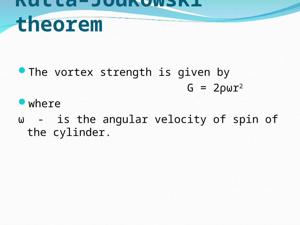
The vortex strength is given by G = 2ρωr2
where ω - is the angular velocity of spin of the
cylinder.


Kutta–Joukowski theorem
Like all aerodynamic lift, this seems a bit mysterious, but it can be looked at in terms of a redirection of the air motion. If the cylinder traps some air in a boundary layer at the cylinder surface and carries it around with it, shedding it downward, then it has given some of the air a downward momentum.
Kutta–Joukowski theorem
That can act to give the cylinder an upward momentum in accordance with the principle of conservation of momentum. Another approach is to say that you have exerted a downward component of force on the air and by Newton's 3rd law there must be an upward force on the cylinder.

Kutta–Joukowski theorem
Yet another approach is to say that the top of the cylinder is assisting the airstream, speeding up the flow on the top of the cylinder. Then by the Bernoulli equation, the pressure on the top of the cylinder is diminished, giving an effective lift.

REDUCTION IN FORM DRAG
50%
90 - 95%
85%
Form Drag
VERY TURBULENT WAKE

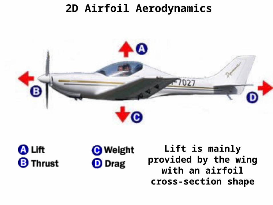
2D Airfoil Aerodynamics
Lift is mainly provided by the wing with an airfoil
cross-section shape

HOW DOES AN AIRFOIL GENERATE LIFT?• Lift due to imbalance of pressure distribution over top and bottom
surfaces of airfoil (or wing)– If pressure on top is lower than pressure on bottom surface, lift is generated– Why is pressure lower on top surface?
• We can understand answer from basic physics:– Continuity (Mass Conservation)– Newton’s 2nd law (Euler or Bernoulli Equation)
Lift = PA

HOW DOES AN AIRFOIL GENERATE LIFT?1. Flow velocity over top of airfoil is faster than over bottom surface
– Streamtube A senses upper portion of airfoil as an obstruction– Streamtube A is squashed to smaller cross-sectional area– Mass continuity AV=constant: IF A↓ THEN V↑
Streamtube A is squashedmost in nose region(ahead of maximum thickness)
AB

HOW DOES AN AIRFOIL GENERATE LIFT?
2. As V ↑ p↓– Incompressible: Bernoulli’s Equation– Compressible: Euler’s Equation– Called Bernoulli Effect
3. With lower pressure over upper surface and higher pressure over bottom surface, airfoil feels a net force in upward direction → Lift
VdVdp
Vp
constant2
1 2
Most of lift is producedin first 20-30% of wing(just downstream of leading edge)

WHAT CREATES AERODYNAMIC FORCES?
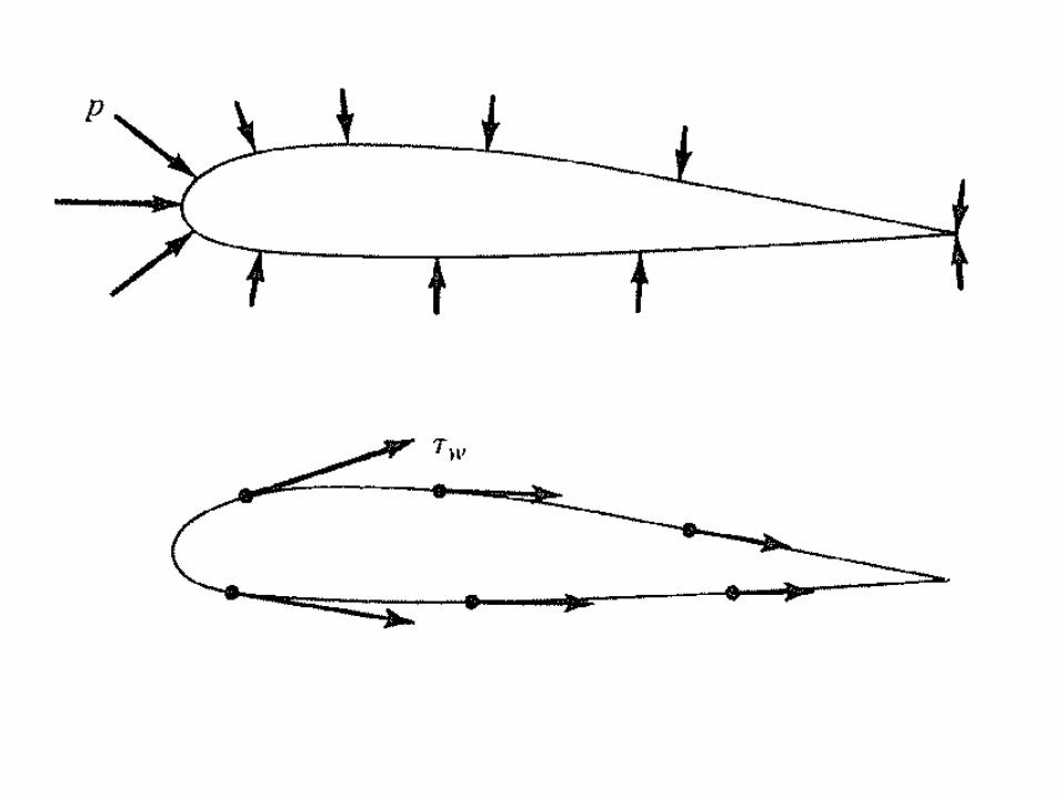
• Aerodynamic forces exerted by airflow comes from only two sources:
1. Pressure, p, distribution on surface• Acts normal to surface
2. Shear stress, w, (friction) on surface• Acts tangentially to surface
• Pressure and shear are in units of force per unit area (N/m2)
• Net unbalance creates an aerodynamic force
Dr. Shehret Tilvaldyev16
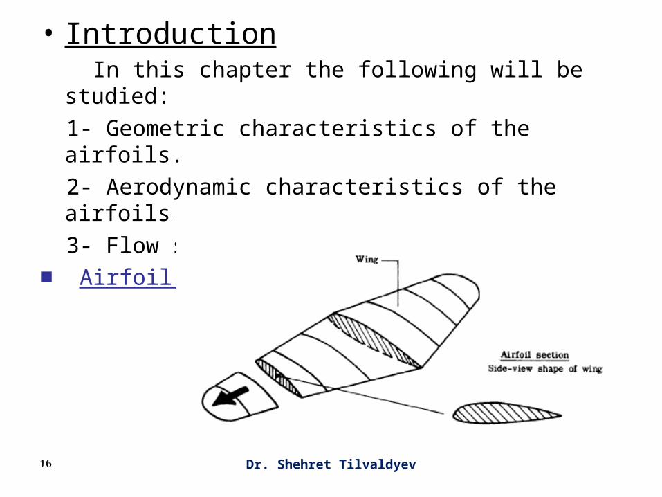
• Introduction In this chapter the following will be studied:
1- Geometric characteristics of the airfoils.
2- Aerodynamic characteristics of the airfoils.
3- Flow similarity ( Dynamic similarity )
■ Airfoil Geometric Characteristics

17

Airfoil Geometry
An airfoil is the 2D cross-section shape of the wing, which creates sufficient lift
with minimal drag

Dr. Shehret Tilvaldyev19
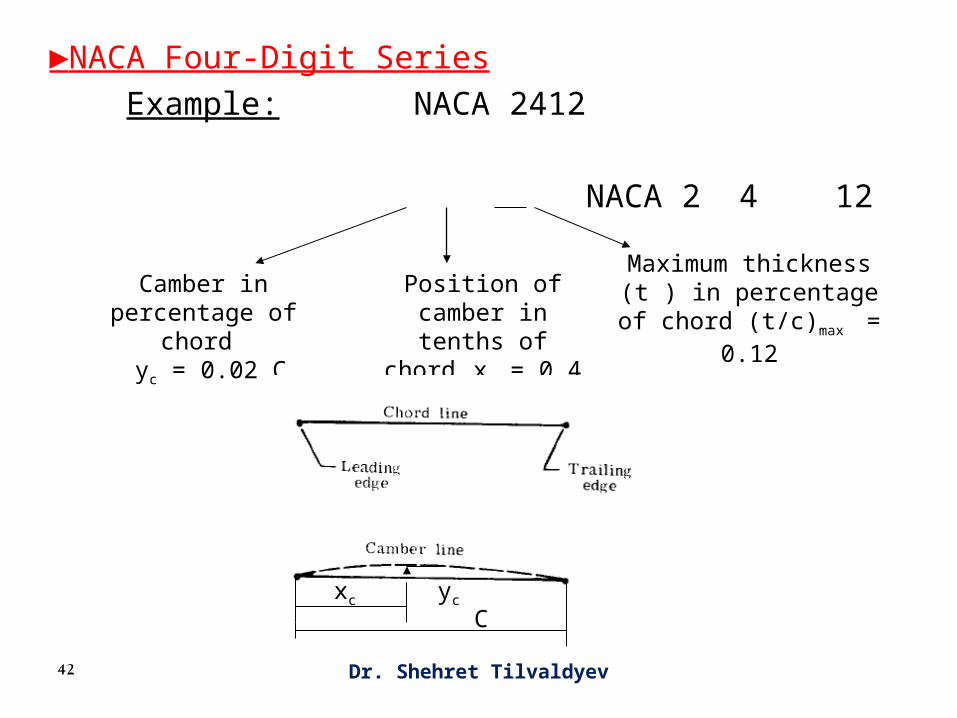
Airfoil geometric characteristics include:1- Mean camber line : The locus (the specific location) of points halfway between the upper and lower surfaces as measured perpendicular to the mean camber line.2- Leading & trailing edges: The most forward and rearward points of the mean camber line.3- Chord line: The straight line connecting the leading and trailing edges.
Dr. Shehret Tilvaldyev20
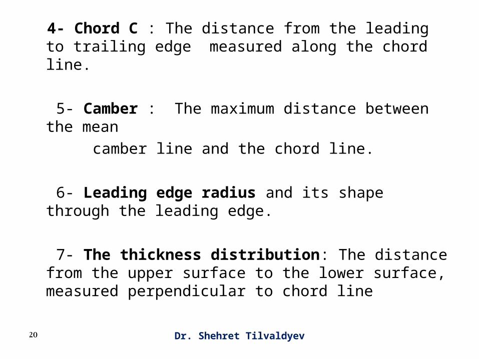
4- Chord C : The distance from the leading to trailing edge measured along the chord line.
5- Camber : The maximum distance between the mean
camber line and the chord line.
6- Leading edge radius and its shape through the leading edge.
7- The thickness distribution: The distance from the upper surface to the lower surface, measured perpendicular to chord line
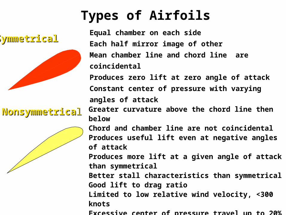
Types of Airfoils
SymmetricalSymmetricalEqual chamber on each side
Each half mirror image of other
Mean chamber line and chord line are coincidental
Produces zero lift at zero angle of attack
Constant center of pressure with varying angles of
attack
NonsymmetricaNonsymmetricall Greater curvature above the chord line then belowChord and chamber line are not coincidentalProduces useful lift even at negative angles of attackProduces more lift at a given angle of attack than symmetricalBetter stall characteristics than symmetricalGood lift to drag ratioLimited to low relative wind velocity, <300 knotsExcessive center of pressure travel up to 20% of chord line

Airfoil
Chord Line
Camber LineEqual amounts of thickness is added to camber
in a direction normal to the camber line.
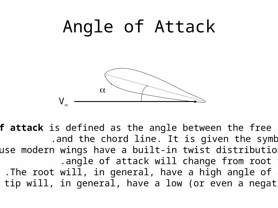
Angle of Attack
V
Angle of attack is defined as the angle between the free streamand the chord line. It is given the symbol (.
Because modern wings have a built-in twist distribution, theangle of attack will change from root to tip.
The root will, in general, have a high angle of attack.The tip will, in general, have a low (or even a negative) .
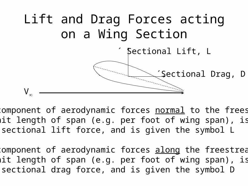
Lift and Drag Forces acting on a Wing Section
Sectional Drag, D´
Sectional Lift, L´
The component of aerodynamic forces normal to the freestream ,per unit length of span (e.g. per foot of wing span), is called
the sectional lift force, and is given the symbol L.´
The component of aerodynamic forces along the freestream ,per unit length of span (e.g. per foot of wing span), is called
the sectional drag force, and is given the symbol D.´
V

Sectional Lift and Drag Coefficients
•The sectional lift coefficient Cl is defined as:
•Here (c) is the airfoil chord, i.e. distance between the leading edge and trailing edge, measured along the chordline.
•The sectional drag force coefficient Cd is likewise defined as:
cV
LCl
2
21
cV
DCd
2
21
2D Airfoil Aerodynamics
Lift is mainly provided by the wing with an airfoil
cross-section shape

Lift & Drag Coefficients
Chord Line
normal forcelift
V
drag
chordwise force
SV
lcl 2
2
1
SV
dcd 2
2
1
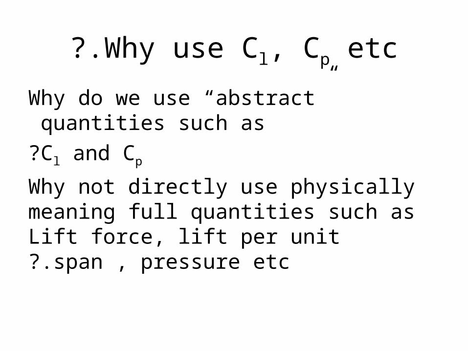
Why use Cl, Cp etc?.
Why do we use “abstract” quantities such as
Cl and Cp?
Why not directly use physically meaning full quantities such as Lift force, lift per unit
span , pressure etc?.
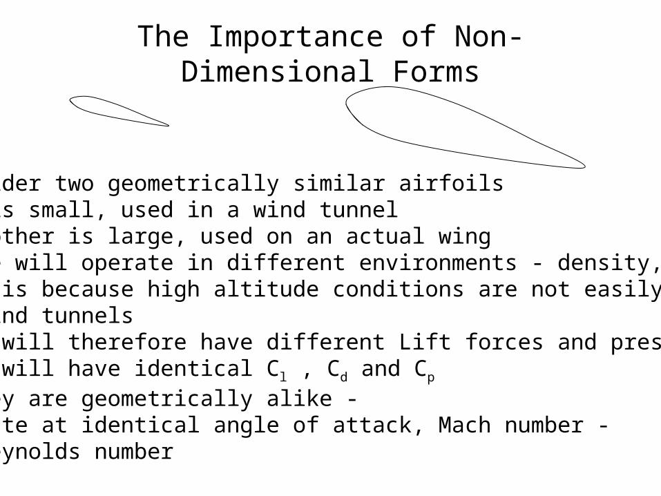
The Importance of Non-Dimensional Forms
Consider two geometrically similar airfoils.One is small, used in a wind tunnel.The other is large, used on an actual wing.These will operate in different environments - density, velocity.This is because high altitude conditions are not easily reproduced in wind tunnels.They will therefore have different Lift forces and pressure fields.They will have identical Cl , Cd and Cp
-if they are geometrically alike -operate at identical angle of attack, Mach number
and Reynolds number

The Importance of Non-Dimensional Forms
In other words ,a small airfoil , tested in a wind tunnel,
and a large airfoil, used on an actual wingwill have identical non-dimensional coefficients Cl , Cd and Cp
-if they are geometrically alike -operate at identical angle of attack, Mach number
and Reynolds number.
This allows designers (and engineers) to build and testsmall scale models, and extrapolate qualitative features,
but also quantitative information, from a small scale modelto a full size configuration.
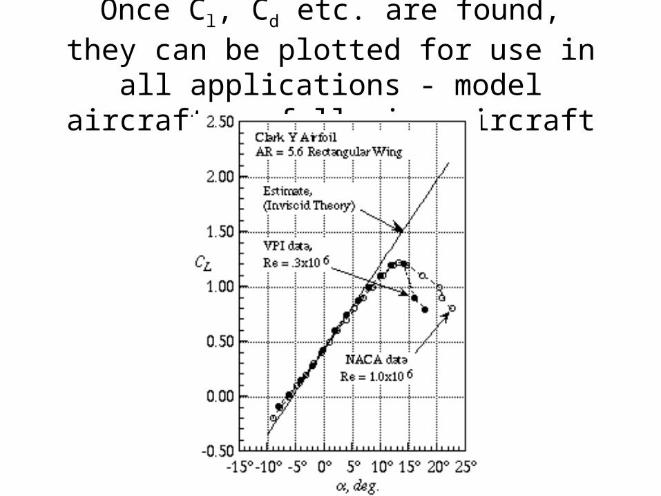
Once Cl, Cd etc. are found, they can be plotted for use in all applications - model
aircraft or full size aircraft
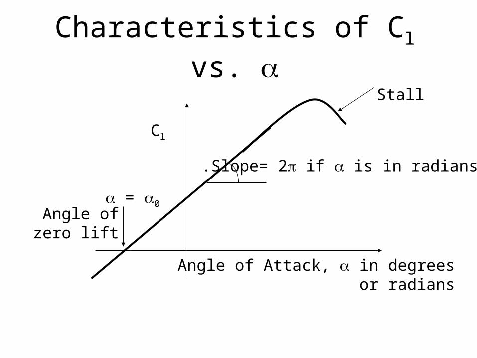
Characteristics of Cl vs.
Angle of Attack, in degrees or radians
Cl
Slope= 2 if is in radians.
= 0Angle ofzero lift
Stall

The angle of zero lift depends onthe camber of the airfoil
Angle of Attack, in degrees or radians
Cl
= 0Angle ofzero lift
Cambered airfoil
Symmetric Airfoil

Drag is caused bySkin Friction - the air molecules try to drag the airfoil with them. This effect is due to viscosity.
Form Drag - The flow separates near the trailing edge, due to the shape of the body. This causes low pressures near the trailing edge compared to the leading edge. The pressure forces push the airfoil
back .
Wave Drag: Shock waves form over the airfoil, converting momentum of the flow into heat. The resulting rate of change of momentum causes drag.
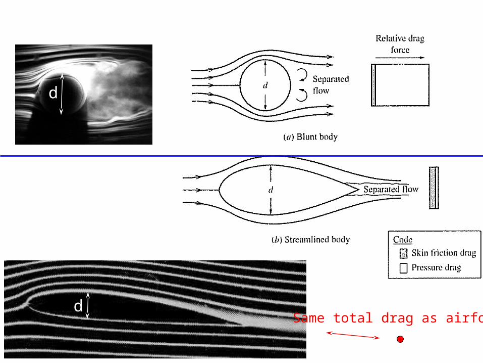
DRAG FORCES
d
d
Same total drag as airfoil

Viscous Boundary Layer
Transition Separation
1 23
4
V Edge of boundary layer
Velocity profile creates skin friction (shear) drag on surface

Note ‘messy’ or turbulent flow pattern
High drag
Lower fuel efficiency
Spoiler angle increased by + 5°
Flow behavior more closely resembles a laminar flow
Tremendous savings (> $10,000/yr) on Miami-NYC route

Historical Airfoils

Evolution of Airfoil Design
Laminar boundary layer creates less skin
friction drag

Dr. Shehret Tilvaldyev40
►Airfoil Families (Series)
# NACA (National Advisory Committee for Aeronautics) or
NASA (National Aeronautics and Space administration)
identified different airfoil shapes with a logical numbering
system.
# Abbott & Von Doenhoff “ Theory of Wing Sections” includes a summary of airfoil data ( geometric and aerodynamic data )
Dr. Shehret Tilvaldyev41
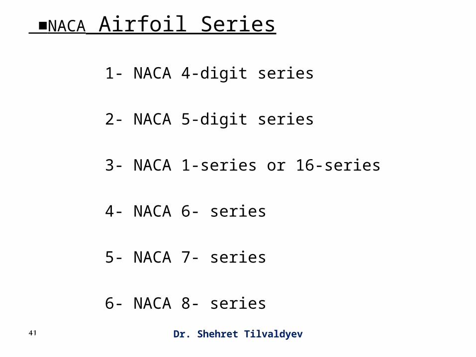
■NACA Airfoil Series
1- NACA 4-digit series
2- NACA 5-digit series
3- NACA 1-series or 16-series
4- NACA 6- series
5- NACA 7- series
6- NACA 8- series
Dr. Shehret Tilvaldyev42
►NACA Four-Digit Series
Example: NACA 2412
NACA 2 4 12
Camber in percentage of chord
yc = 0.02 C
Position of camber in tenths of chord
xc = 0.4 C
Maximum thickness (t ) in percentage of chord
(t/c)max = 0.12
xc yc
C

Dr. Shehret Tilvaldyev43

Dr. Shehret Tilvaldyev44
►NACA Five-Digit Series
Example: NACA 23012
NACA 2 30 12
When multiplied by 3/2
yields the design lift coefficient Cl in tenths.
Cl = 0.3
When divided by 2, gives the position of the
camber in percent of chord xc = 0.15 C
Maximum thickness (t ) in percentage of chord (t/c)max = 0.12
Dr. Shehret Tilvaldyev45
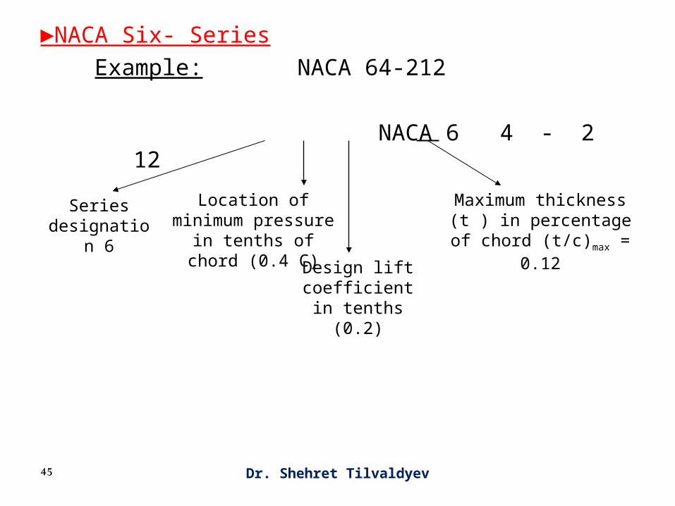
►NACA Six- Series
Example: NACA 64-212
NACA 6 4 - 2 12
Series designation 6
Location of minimum pressure in tenths of
chord (0.4 C)
Design lift coefficient in tenths (0.2)
Maximum thickness (t ) in percentage of chord
(t/c)max = 0.12

y46
• The Handbook “Theory of Wing Sections” gives the shape of airfoils in terms of upper and lower surfaces station and ordinate as given in the following Tables.
• Airfoils can be drawn using these Tables.• From airfoil drawing we can extract its geometric data:
- camber line
- maximum camber ratio and its position
- maximum thickness ratio and its position
-leading edge radius
-trailing edge angle

Dr. Shehret Tilvaldyev47
• Tabe for NACA 2410, 2412, 2415
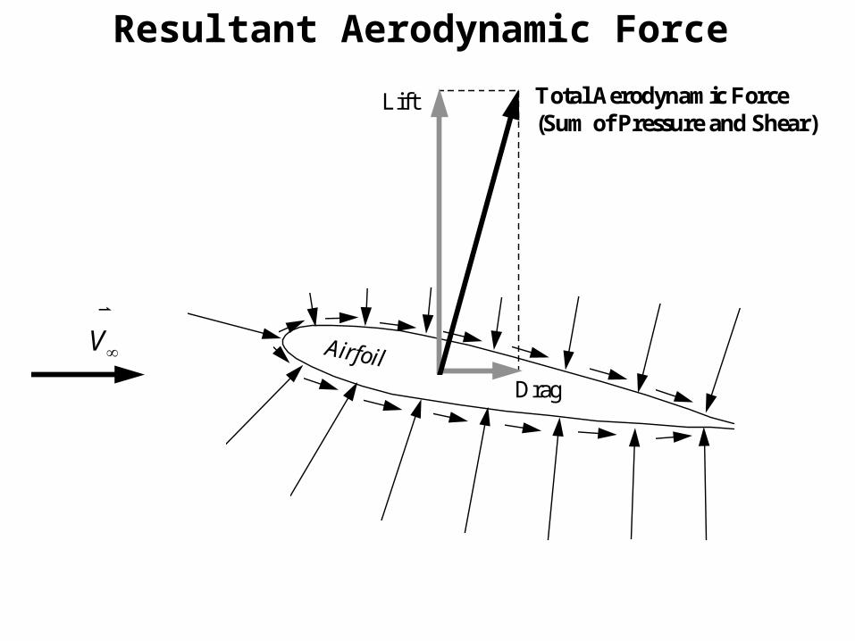
Resultant Aerodynamic Force
Airfoil
Total Aerodynamic Force(Sum of Pressure and Shear)
Lift
Drag
V

Dr. Shehret Tilvaldyev49
■Center of Pressure and Aerodynamic Center
# Center of pressure : The point of intersection between the chord line and the line of action of the resultant aerodynamic force R.
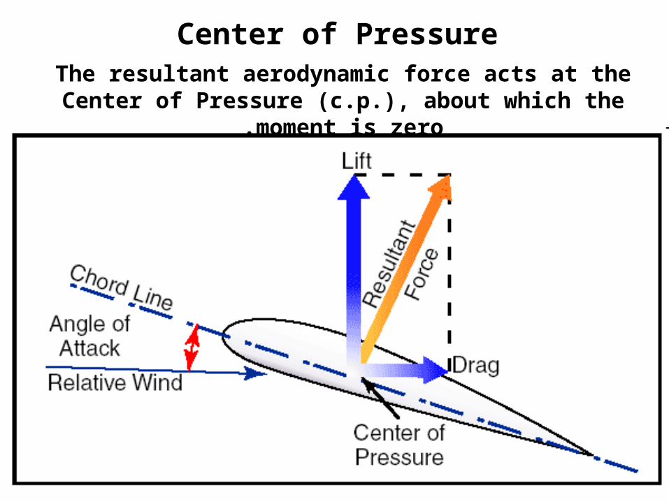
Center of PressureThe resultant aerodynamic force acts at the Center of
Pressure (c.p.), about which the moment is zero.

Typical Streamlines
Angle of Attack
chord lineV

Pressure Coefficient Distribution
02
2
1
V
ppcp
2
2
1
V
ppcp
In free-stream :
At stagnation point (V=0) : 12
2
1
2
2
1
2
2
10
0
V
V
V
ppcp
Positive Cp means the pressure is higher than the free-stream (atmospheric) pressure, and negative Cp means suction relative to free-stream pressure. The maximum,
which occurs at the stagnation point, is always 1 .

Viscous Boundary Layer
Transition Separation
1 23
4
V Edge of boundary layer
Velocity profile creates skin friction (shear) drag on surface

Boundary Layer Flow Separation
When flow separation occurs ,there is also pressure drag.
55
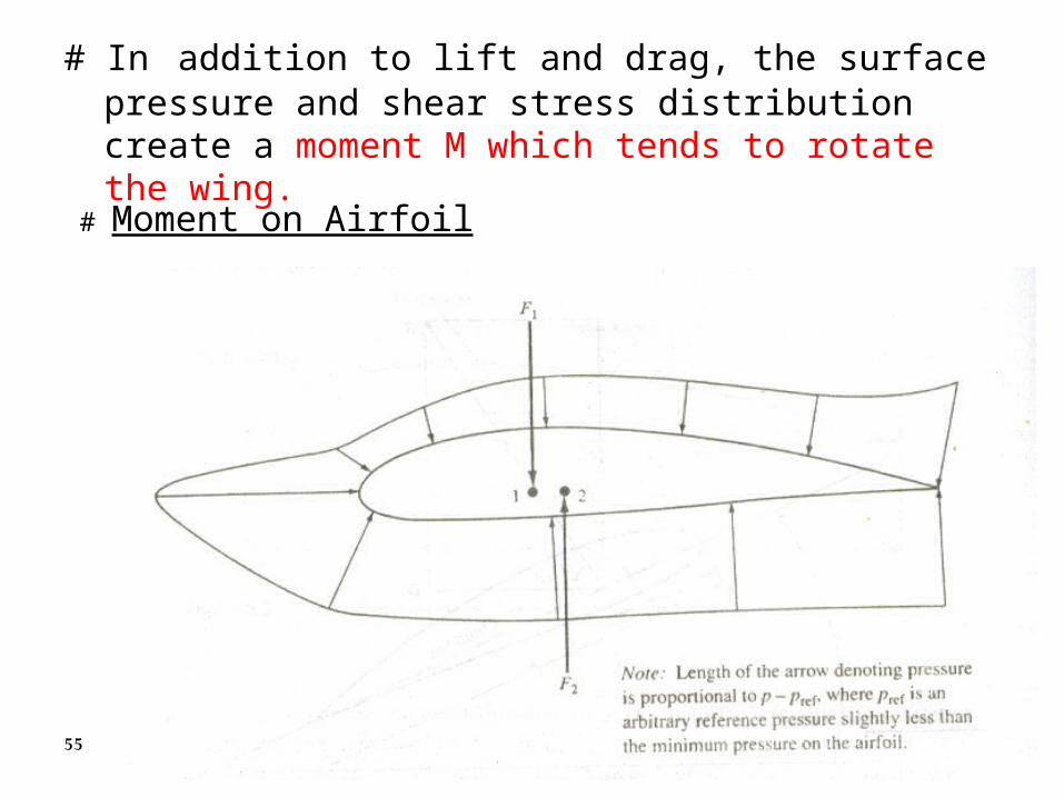
# In addition to lift and drag, the surface pressure and shear stress distribution create a moment M which tends to rotate the wing.
# Moment on Airfoil
y56
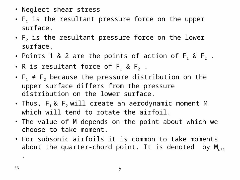
• Neglect shear stress
• F1 is the resultant pressure force on the upper surface.
• F2 is the resultant pressure force on the lower surface.
• Points 1 & 2 are the points of action of F1 & F2 .
• R is resultant force of F1 & F2 .
• F1 ≠ F2 because the pressure distribution on the upper surface differs from the pressure distribution on the lower surface.
• Thus, F1 & F2 will create an aerodynamic moment M which will tend to rotate the airfoil.
• The value of M depends on the point about which we choose to take moment.
• For subsonic airfoils it is common to take moments about the quarter-chord point. It is denoted by Mc/4 .

Dr. Shehret Tilvaldyev57
Mc/4 is function of angle of attack α, i.e. its value depends on α .

Dr. Shehret Tilvaldyev58
■ Aerodynamic Center
≠ Aerodynamic center: The point on the chord line about which moments does not vary with α.
●The moment about the aerodynamic center (ac) is designated Mac .
● By definition, Mac = constant ● For low-speed and subsonic airfoils, AC is generally very
close to the quarter-chord point
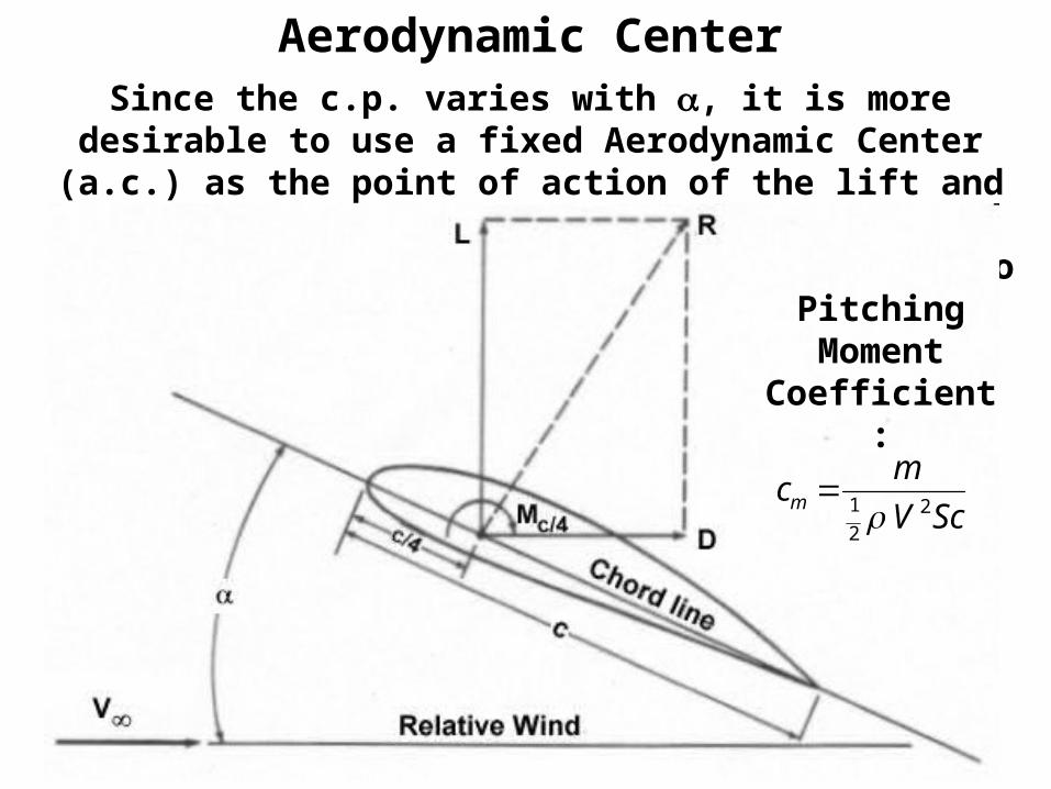
Since the c.p. varies with , it is more desirable to use a fixed Aerodynamic Center (a.c.) as the point of action of the lift and drag. The pitching moment about this point
can be calculated, and is found insensitive to . For most airfoils, the a.c. locates at around quarter chord (x=c/4).
Aerodynamic Center
cm
V Scm
1
22
Pitching Moment
Coefficient:
Dr. Shehret Tilvaldyev60
■Lift, Drag, and Moment Coefficients
For an airplane in flight, L, D, and M depend on:1- Angle of attack α2- Free-stream velocity V∞
3- Free-stream density ρ∞ , that is, altitude4- Viscosity coefficient µ∞
5- Compressibility of the airflow which is governed by Mach number M∞ = V∞/a∞. 6- Size of the aerodynamic surface. For airplane we use the plan form wing area S to indicate size.7- Shape of the airfoil

Computation Fluid Dynamics Simulation
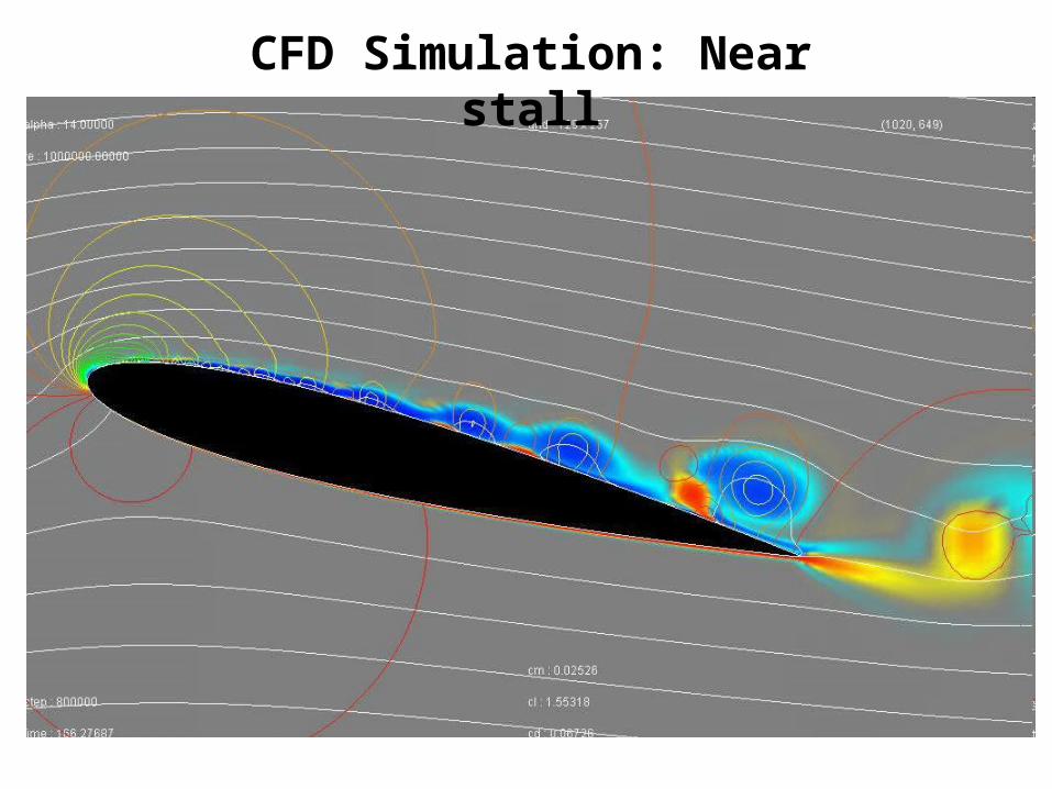
CFD Simulation: Near stall

CFD Simulation: Fully Stalled


